
SLR5000.pdf
12
APPLICANT: MOTOROLA SOLUTIONS EQUIPMENT TYPE: ABZ99FT4096 109AB-99FT4096 EXHIBIT D User Information User Information Tune-up and user / operational manual information are provided in the following exhibits. EXHIBIT DESCRIPTION D1 Tune-Up Procedure D2 User / Operational Manual
Transcript of SLR5000.pdf

APPLICANT: MOTOROLA SOLUTIONS EQUIPMENT TYPE: ABZ99FT4096 109AB-99FT4096
EXHIBIT D
User Information User Information Tune-up and user / operational manual information are provided in the following exhibits. EXHIBIT DESCRIPTION
D1 Tune-Up Procedure
D2 User / Operational Manual

APPLICANT: MOTOROLA SOLUTIONS EQUIPMENT TYPE: ABZ99FT4096 109AB-99FT4096
EXHIBIT D1
Tune-Up Procedure Tune-Up Procedure A procedure to ensure that the device is tuned to the correct frequency / frequency range and that it is operating at the proper level. This exhibit is only required for licensed transmitters. Draft content from Chapter 10 of the document “MOTOTRBO™ SLR 5700 Repeater Basic Service and Installation Manual” (part number MN001436A01-AA, February 2015) is included in the following pages.

FTR Draft 2
Chapter 10 SLR 5000 Series Programming and Tuning10.1 IntroductionThis chapter provides an overview of the MOTOTRBO Customer Programming Software (CPS) and the MOTOTRBO Tuner application for use on Windows 7TM, Windows 8TM, or Windows 8.1TM. These two MOTOTRBO applications are used for the configuration and alignment of the SLR 5000 series repeater.
10.2 Customer Programming Software Setup
The Customer Programming Software setup, shown in Figure 10-1 is used to program the repeater. See Figure 10-2 and Figure 10-3 for the actual connectors on the front and rear panels of the repeater.
Note See appropriate program on-line help files for the programming procedures.
Computer USB ports can be sensitive to Electronic Discharge. Employ proper ESD practices (wrist strap, grounding, etc.) and do not touch exposed contacts on cables when connected to a computer.
Figure 10-1 Customer Programming Software Setup
Front Panel
USB
AC
USB
120 / 240 VAC
Station
Tx Port(N-type Female)
Rx Port(BNC Female)
AUX
DC13.6 VDC
Either One or Both
Standard Type “A” to Type “B” USB cable
Rear Panel

10-2 SLR 5000 Series Programming and Tuning: Repeater Tuning SetupFTR Draft 2
Figure 10-2 Front view of SLR 5000 Series Repeater
Figure 10-3 Rear view of SLR 5000 Series Repeater
10.3 Repeater Tuning Setup
A personal computer (PC), Windows TM operating system, and the MOTOTRBO Tuner application are required to align the repeater. To perform the tuning procedures, the repeater must be connected to the PC and test equipment setup as shown in Figure 10-4.
Figure 10-4 SLR 5000 Series Repeater Tuning Equipment Setup
USB Port
AC Inlet Connector DC Inlet Connector Aux Connector Rx RF Connector Tx RF Connector
TransmitService Monitor
or Counter
Wattmeter20 dB Pad
Front Panel
AC
USB
120 / 240 VAC
Station
Tx Port(BNC Female)
AUX
DC13.6 VDCEither
One or Both
Rear Panel
Standard Type “A” to Type “B” USB cable
USB

SLR 5000 Series Programming and Tuning: Rx Audio Level Set 10-3FTR Draft 2
10.4 Rx Audio Level SetThe procedure outlined in this section is used to set the receive output audio level from the repeater for a given RF deviation of the received RF signal. Perform this procedure any time the Rx audio level needs adjustment.
10.4.1 Tuning Procedure
1. Connect the repeater’s receiver antenna port to the Communication Analyzer.2. Power the repeater from either an AC or DC source.3. Launch the Tuner application and click the “Read” button to read the softpot values.4. Select “Rx Rated Volume” under the Rx menu in the tree view (See Figure 10-5).
Figure 10-5 Rx Menu tree (Rx Rated Volume)
5. Set the Communication Analyzer to output a -47 dBm RF signal modulated with a 1 kHz tone at 60% of full deviation on the tuning frequency. The tuning frequency is the value displayed on the Tuner GUI under the heading of “Frequency Points”.
6. Adjust the softpot value until the desired receive audio level is achieved at pin #7 (in reference to ground) on the Aux connector. Ground connections provided by the Aux connector are pins: 9, 16, 17, 18, and 19.
Note The Tuner aligns this parameter in a 12.5 kHz channel spacing, so 60% is 1.5 kHz of deviation. If the CPS is set for 25 kHz operation, the repeater will automatically scale the deviation by a factor of two when it is outside the Tuner environment.
Note Programmed TPL and DPL squelch requirements are automatically disabled for the tuning frequency while in the Tuner environment.
10-4 SLR 5000 Series Programming and Tuning: Tx Audio Level SetFTR Draft 2
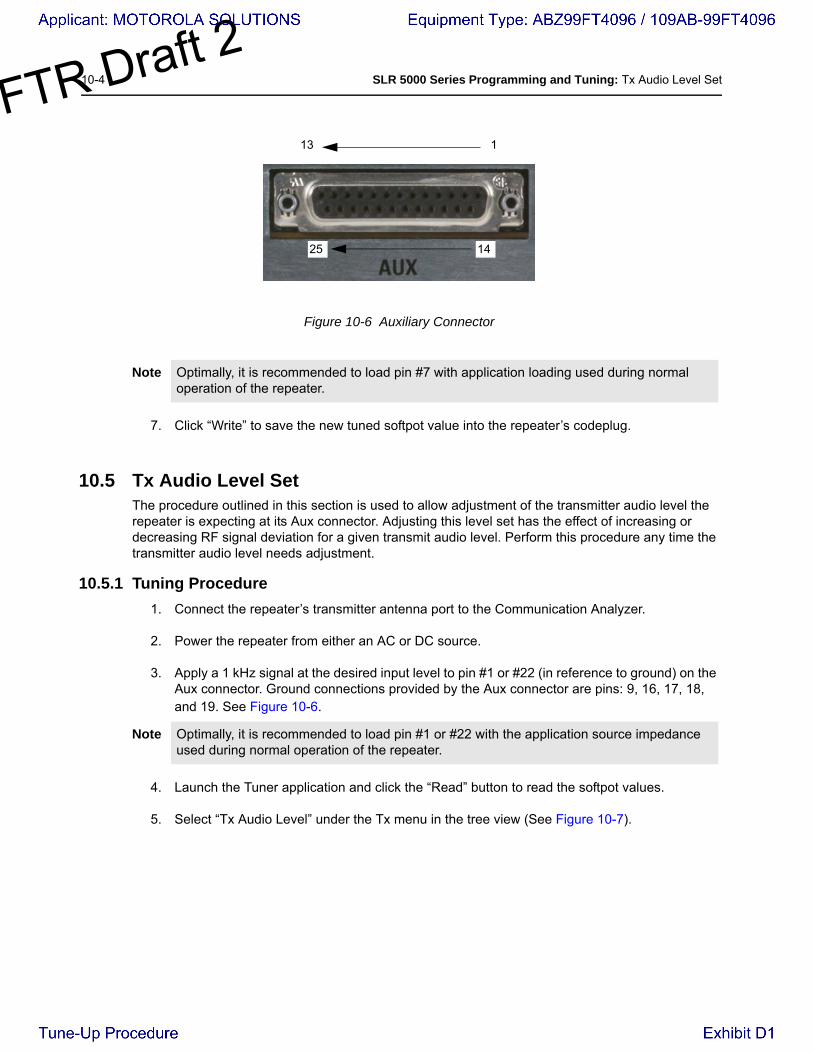
Figure 10-6 Auxiliary Connector
7. Click “Write” to save the new tuned softpot value into the repeater’s codeplug.
10.5 Tx Audio Level SetThe procedure outlined in this section is used to allow adjustment of the transmitter audio level the repeater is expecting at its Aux connector. Adjusting this level set has the effect of increasing or decreasing RF signal deviation for a given transmit audio level. Perform this procedure any time the transmitter audio level needs adjustment.
10.5.1 Tuning Procedure
1. Connect the repeater’s transmitter antenna port to the Communication Analyzer.
2. Power the repeater from either an AC or DC source.
3. Apply a 1 kHz signal at the desired input level to pin #1 or #22 (in reference to ground) on the Aux connector. Ground connections provided by the Aux connector are pins: 9, 16, 17, 18, and 19. See Figure 10-6.
4. Launch the Tuner application and click the “Read” button to read the softpot values.
5. Select “Tx Audio Level” under the Tx menu in the tree view (See Figure 10-7).
Note Optimally, it is recommended to load pin #7 with application loading used during normal operation of the repeater.
Note Optimally, it is recommended to load pin #1 or #22 with the application source impedance used during normal operation of the repeater.
13 1
1425

SLR 5000 Series Programming and Tuning: Reference Oscillator Alignment 10-5FTR Draft 2
Figure 10-7 Tx Menu Tree (Tx Audio Level)
6. Enter the tuning frequency into the Communication Analyzer (the value displayed on the Tuner GUI under the heading of “Frequency Points”).
7. Click the “PTT Toggle” button within the Tuner environment to key up the repeater.
8. Adjust the softpot value until 60% of the rated system deviation (RSD) is achieved.
9. Click the “PTT Toggle” button within the Tuner environment to de-key the repeater.
10. Click “Write” to save the new tuned softpot value into the repeater’s codeplug.
10.6 Reference Oscillator AlignmentThis feature is used to adjust the reference oscillator of the repeater. This alignment process should be done as maintenance schedules and regulations require or if the Modem FRU has been replaced in the repeater.
10.6.1 Tuning Procedure
1. Connect the repeater’s transmitter antenna port to the Communication Analyzer.
2. Power the repeater from either an AC or DC source.
3. Click the “Read” button in the tuner to begin reading the repeater’s tuning softpot values.
4. Select “Ref Oscillator’ under the TX menu in the tree view (See Figure 10-6).
Note The Tuner aligns this parameter in a 12.5 kHz channel spacing, so 60% is 1.5 kHz of deviation. If the CPS is set for 25 kHz operation, the repeater will automatically scale the deviation by a factor of two when it is outside the Tuner environment.

10-6 SLR 5000 Series Programming and Tuning: Reference Oscillator AlignmentFTR Draft 2
Figure 10-8 Tx Menu Tree (Ref. Oscillator)
5. Configure the current operating frequency into the Communications Analyzer.
6. Click the “PTT Toggle” button to key up the repeater.
7. Adjust the working softpot value until the frequency is within the performance specifications (+/- 40 Hz for UHF and VHF) from the frequency point.
8. Click the “PTT Toggle” button to de-key the repeater.
9. Click the “Write” button to save the tuned softpot value into the repeater codeplug.
SLR 5000 Series Programming and Tuning: Modulation Limit Alignment 10-7FTR Draft 2
10.7 Modulation Limit AlignmentThis feature is to set the modulation limit of the SLR 5000 Series Repeater.
10.7.1 Tuning Procedure (with no Tx Data and no PL)
1. Connect the repeater’s antenna port to the attenuation pad, if necessary, before connecting to the Communication Analyzer.
2. Power the repeater from either an AC or DC source.3. Apply a 1 kHz signal at 1.2 Vrms to Pin 1 of the J7 backplane connector.
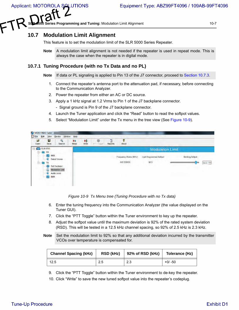
- Signal ground is Pin 9 of the J7 backplane connector.4. Launch the Tuner application and click the “Read” button to read the softpot values.5. Select “Modulation Limit” under the Tx menu in the tree view (See Figure 10-9).
Figure 10-9 Tx Menu tree (Tuning Procedure with no Tx data)
6. Enter the tuning frequency into the Communication Analyzer (the value displayed on the Tuner GUI).
7. Click the “PTT Toggle” button within the Tuner environment to key up the repeater.8. Adjust the softpot value until the maximum deviation is 92% of the rated system deviation
(RSD). This will be tested in a 12.5 kHz channel spacing, so 92% of 2.5 kHz is 2.3 kHz.
9. Click the “PTT Toggle” button within the Tuner environment to de-key the repeater.10. Click “Write” to save the new tuned softpot value into the repeater’s codeplug.
Note A modulation limit alignment is not needed if the repeater is used in repeat mode. This isalways the case when the repeater is in digital mode.
Note If data or PL signaling is applied to Pin 13 of the J7 connector, proceed to Section 10.7.3.
Note Set the modulation limit to 92% so that any additional deviation incurred by the transmitterVCOs over temperature is compensated for.
Channel Spacing (kHz) RSD (kHz) 92% of RSD (kHz) Tolerance (Hz)
12.5 2.5 2.3 +0/ -50

10-8 SLR 5000 Series Programming and Tuning: Modulation Limit AlignmentFTR Draft 2
10.7.2 Verification (with no Tx Data and no PL)1. Connect the repeater’s antenna port to the attenuation pad, if necessary, before connecting to the Communication Analyzer.
2. Power the repeater from either an AC or DC source.3. Via CPS, program the repeater with any frequency within the specified range of the repeater
under test, and set the repeater for low power and disable the repeat path.4. Apply a 1 kHz signal at 1.2 Vrms to Pin 1 of the J7 backplane connector.
- Signal ground is Pin 9 of the J7 backplane connector.5. Key up the repeater and measure the deviation
- Key the repeater by grounding Pin 2 of the J7 backplane connector.- CPS must have Pin 2 configured as an active low with the PTT function.
6. De-key the repeater.
The deviation shall meet the limits shown in the table below.
Channel Spacing(kHz)
Relative Standard Deviation (RSD)(kHz)
92% of RS(kHz)
Tolerance(Hz)
12.5 2.5 2.3 +0/ -50
20.0 4.0 3.68 +0/ -80
25.0 5.0 4.6 +0/ -100
Note • The repeater will be factory-tuned in accordance to the above procedure and specification.
• Verification is performed outside of the Tuner application, i.e. in normal mode.

SLR 5000 Series Programming and Tuning: Modulation Limit Alignment 10-9FTR Draft 2
10.7.3 Tuning Procedure (with Tx Data or PL)1. Connect the repeater’s antenna port to the attenuation pad, if necessary, before connecting to the Communication Analyzer.
2. Turn on the repeater using an AC or DC source.3. Click the “Read” button on the Tuner application to read the repeater’s softpot values.4. Select “Modulation Limit” under the Tx menu in the tree view.5. Enter the tuning frequency into the Communication Analyzer (the value displayed by the
Tuner application).6. Click the “PTT Toggle” button within the Tuner environment to key up the repeater.7. Apply a 1 kHz signal at 1.2Vrms to Pin 22 of the J7 backplane connector.
- Signal ground is Pin 9 of the J7 backplane connector.- If the manufacturer of the third party controller specifies that the Tx Audio is not to be
pre-emphasized, use Pin 1 instead of Pin 22.8. Adjust the Modulation Limit softpot to a value that limits the maximum deviation to “X”% RSD,
where “X” is equal to “92% RSD” minus “Tx Data’s % RSD”.
E.g. If Tx Data deviation is equal to 17%,
X = 92% - 17% = 75% as the maximum deviation limit.
Figure 10-10 Example of maximum deviation limit calculation
9. Click the “PTT Toggle” button within the Tuner environment to de-key the repeater.10. Click “Write” to save the newly tuned softpot value into the repeater’s codeplug.
11. Alignment is complete.
Note See Figure 3-3 for details regarding the audio and data flow.
Note Set the modulation limit to 92% to compensate for any additional deviation incurred by thetransmitter VCOs over temperature.
Note The Tuner application always aligns the Modulation Limit parameter in a 12.5 kHz channelspacing regardless of the CPS setting, so calculate the tuning % RSD accordingly. If theCPS is set for 25 kHz operation, the repeater will automatically scale the deviation by afactor of two when outside of the Tuner environment.
8%
17%
75%
100%
0%
%RSD 92%
With Tx Data or PL
Buffer
Data or PL
Voice

10-10 SLR 5000 Series Programming and Tuning: Modulation Limit AlignmentFTR Draft 2
10.7.4 Verification (with Tx Data or PL)See Section 10.7.2 with the following exceptions:
• The same Tx data signal level determined (obtained from Step 8 in Section 10.7.3), is applied to Pin 13 during the validation process.
• Pin 22 may be used instead of Pin 1, depending on the recommendation by the manufacturer of the third party controller.


