
Slot-type Photomicrosensor EE-SX97 - Omron · 1 CSM_EE-SX97_DS_E_1_3 Slot-type Photomicrosensor...
9
1 CSM_EE-SX97_DS_E_1_3 Slot-type Photomicrosensor EE-SX97 Built-in connector enables downsizing and easier connection. Protective circuit for safe operation. • A built-in connector minimizes the shape and dimensional requirements. • Two outputs: light-ON and dark-ON. • Complete lineup including seven different shapes. • Safer operation with built-in power supply reverse polarity protection. • Output overcurrent protection with a thermal shutdown circuit (patent pending). *1 • The indicator can be seen from many directions to enable installation in more locations. • Connector with lock that mates with commercially available connectors. *2 *1. Output overcurrent protection is provided only on output 2 (OUT2) on NPN models. *2. Recommended connector: J.S.T. Mfg. Co., Ltd. Contacts: SPHD-001T-P0.5, Housing: PAP-04V-S Ask the manufacturer of the connector for details. Be sure to read the Safety Precautions on page 5. For the most recent information on models that have been certified for safety standards, refer to your OMRON website. Features Built-in Connector for Downsizing and Easier Connection A built-in connector minimizes the shape and dimensional requirements. And wiring costs can be reduced by using commercially available connectors. Safer Operation with Built-in Power Supply Reverse Polarity Protection The built-in power supply reverse polarity protection protects against reverse connection of the power supply or outputs for safer operation at the assembly site. Built-in Thermal Shutdown Circuit Control output 2 on models with NPN outputs is protected from output overcurrents by a built-in thermal shutdown circuit. Easy-to-see Indicator The indicator can be seen from up to four directions to enable installation in more locations. Two Outputs: Light-ON and Dark-ON All models provide both a light-ON and dark-ON output so that the output can be switched according to the application simply by changing the wiring. Previous Model 22.2 22.0 (16.2) (2.2) EE-SX97 Series Approx. 40% Smaller Recommended Connector: J.S.T. Mfg. Co., Ltd. Contacts: SPHD-001T-P0.5, Housing: PAP-04V-S *Ask the manufacturer of the connector for details. Use Commercial Connectors The use of a commercially available connector simplifies connections and the positive lock holds the connector in place. Reverse polarity protection NPN GND (0 V) OUT2 OUT1 (Control output) (Control output) Vcc Load 1 5 to 24 VDC Load 2 Main circuit 1 2 3 4 Light indicator (orange) Display
Transcript of Slot-type Photomicrosensor EE-SX97 - Omron · 1 CSM_EE-SX97_DS_E_1_3 Slot-type Photomicrosensor...

1
CSM_EE-SX97_DS_E_1_3
Slot-type Photomicrosensor
EE-SX97Built-in connector enables downsizing and easier connection. Protective circuit for safe operation. • A built-in connector minimizes the shape and dimensional
requirements.• Two outputs: light-ON and dark-ON.• Complete lineup including seven different shapes. • Safer operation with built-in power supply reverse polarity
protection.• Output overcurrent protection with a thermal shutdown
circuit (patent pending). *1• The indicator can be seen from many directions to enable
installation in more locations. • Connector with lock that mates with commercially available
connectors. *2*1. Output overcurrent protection is provided only on output 2 (OUT2) on NPN models. *2. Recommended connector:
J.S.T. Mfg. Co., Ltd. Contacts: SPHD-001T-P0.5, Housing: PAP-04V-SAsk the manufacturer of the connector for details.
Be sure to read the Safety Precautions on page 5.
For the most recent information on models that have been certified for safety standards, refer to your OMRON website.
Features
Built-in Connector for Downsizing and Easier ConnectionA built-in connector minimizes the shape and dimensional requirements. And wiring costs can be reduced by using commerciallyavailable connectors.
Safer Operation with Built-in Power Supply Reverse Polarity ProtectionThe built-in power supply reverse polarity protection protectsagainst reverse connection of the power supply or outputs forsafer operation at the assembly site.
Built-in Thermal Shutdown CircuitControl output 2 on models with NPN outputs is protected fromoutput overcurrents by a built-in thermal shutdown circuit.
Easy-to-see IndicatorThe indicator can be seen from up to four directions to enableinstallation in more locations.
Two Outputs: Light-ON and Dark-ONAll models provide both a light-ON and dark-ON output so thatthe output can be switched according to the application simplyby changing the wiring.
Previous Model
22.2 22.0
(16.2)(2.2)
EE-SX97 Series
Approx.
40% Smaller
Recommended Connector: J.S.T. Mfg. Co., Ltd. Contacts: SPHD-001T-P0.5, Housing: PAP-04V-S *Ask the manufacturer of the connector for details.
Use Commercial Connectors
The use of a commercially available connector simplifies connections and the positive lock holds the connector in place.
Reverse polarity protection
NPN
GND (0 V)
OUT2
OUT1(Control output)
(Control output)
Vcc
Load 1
5 to 24 VDC
Load 2Main circuit
1
2
3
4
Light indicator (orange)
Display

2
EE-SX97Ordering Information
Sensors
Accessories (Order Separately)
AppearanceSensing method
Connecting method
Sensing distanceOperating
modeIndicator
mode
Model
NPN output PNP output
Through-beam type (with slot)
Connector model (4 poles)
Dark-ON/Light-ON(2 outputs)
Incident light
EE-SX970-C1 EE-SX970P-C1
EE-SX971-C1 EE-SX971P-C1
EE-SX972-C1 EE-SX972P-C1
EE-SX974-C1 EE-SX974P-C1
EE-SX975-C1 EE-SX975P-C1
EE-SX976-C1 EE-SX976P-C1
EE-SX977-C1 EE-SX977P-C1
Infrared light
Standard
5 mm (slot width)
L-shaped
T-shaped,slot center7 mm
Close-mounting
T-shaped,slot center10 mm
F-shaped
R-shaped
Type Cable length Model
Connector with Cable1 m EE-1017 1M
3 m EE-1017 3M
Connector with Robot Cable1 m EE-1017-R 1M
3 m EE-1017-R 3M
EE-SX97
3
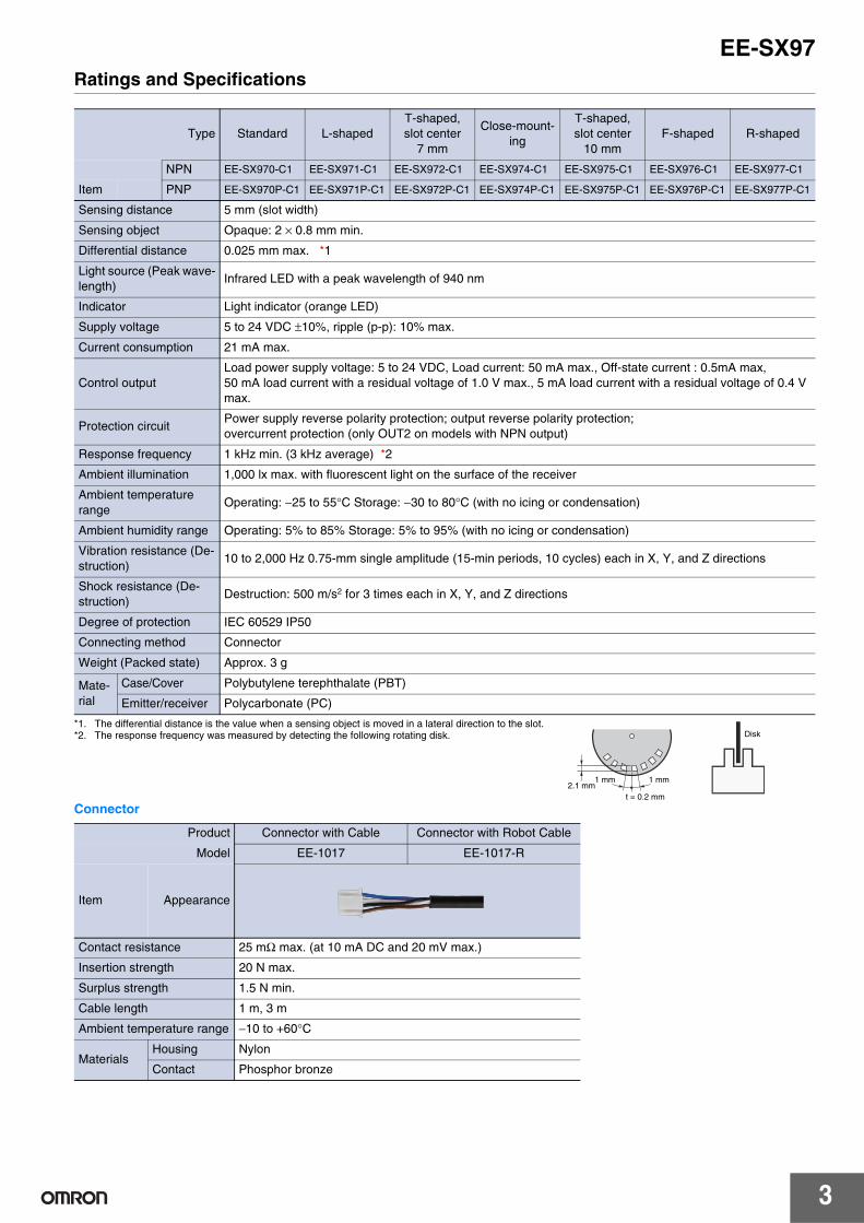
Ratings and Specifications
*1. The differential distance is the value when a sensing object is moved in a lateral direction to the slot.*2. The response frequency was measured by detecting the following rotating disk.
Connector
Type Standard L-shapedT-shaped,slot center
7 mm
Close-mount-ing
T-shaped,slot center
10 mmF-shaped R-shaped
NPN EE-SX970-C1 EE-SX971-C1 EE-SX972-C1 EE-SX974-C1 EE-SX975-C1 EE-SX976-C1 EE-SX977-C1
Item PNP EE-SX970P-C1 EE-SX971P-C1 EE-SX972P-C1 EE-SX974P-C1 EE-SX975P-C1 EE-SX976P-C1 EE-SX977P-C1
Sensing distance 5 mm (slot width)
Sensing object Opaque: 2 × 0.8 mm min.
Differential distance 0.025 mm max. *1
Light source (Peak wave-length)
Infrared LED with a peak wavelength of 940 nm
Indicator Light indicator (orange LED)
Supply voltage 5 to 24 VDC ±10%, ripple (p-p): 10% max.
Current consumption 21 mA max.
Control outputLoad power supply voltage: 5 to 24 VDC, Load current: 50 mA max., Off-state current : 0.5mA max,50 mA load current with a residual voltage of 1.0 V max., 5 mA load current with a residual voltage of 0.4 V max.
Protection circuitPower supply reverse polarity protection; output reverse polarity protection; overcurrent protection (only OUT2 on models with NPN output)
Response frequency 1 kHz min. (3 kHz average) *2
Ambient illumination 1,000 lx max. with fluorescent light on the surface of the receiver
Ambient temperature range
Operating: −25 to 55°C Storage: −30 to 80°C (with no icing or condensation)
Ambient humidity range Operating: 5% to 85% Storage: 5% to 95% (with no icing or condensation)
Vibration resistance (De-struction)
10 to 2,000 Hz 0.75-mm single amplitude (15-min periods, 10 cycles) each in X, Y, and Z directions
Shock resistance (De-struction)
Destruction: 500 m/s2 for 3 times each in X, Y, and Z directions
Degree of protection IEC 60529 IP50
Connecting method Connector
Weight (Packed state) Approx. 3 g
Mate-rial
Case/Cover Polybutylene terephthalate (PBT)
Emitter/receiver Polycarbonate (PC)
Product Connector with Cable Connector with Robot Cable
Model EE-1017 EE-1017-R
Item Appearance
Contact resistance 25 mΩ max. (at 10 mA DC and 20 mV max.)
Insertion strength 20 N max.
Surplus strength 1.5 N min.
Cable length 1 m, 3 m
Ambient temperature range −10 to +60°C
MaterialsHousing Nylon
Contact Phosphor bronze
Disk
1 mm1 mm2.1 mm
t = 0.2 mm
4
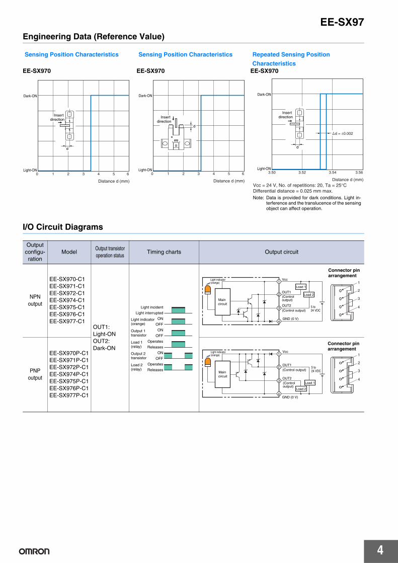
EE-SX97Engineering Data (Reference Value)
I/O Circuit Diagrams
Sensing Position Characteristics Sensing Position Characteristics Repeated Sensing Position
CharacteristicsEE-SX970 EE-SX970 EE-SX970
Output configu-ration
ModelOutput transistor operation status
Timing charts Output circuit
NPN output
EE-SX970-C1EE-SX971-C1EE-SX972-C1EE-SX974-C1EE-SX975-C1EE-SX976-C1EE-SX977-C1
OUT1:Light-ONOUT2:Dark-ON
PNP output
EE-SX970P-C1EE-SX971P-C1EE-SX972P-C1EE-SX974P-C1EE-SX975P-C1EE-SX976P-C1EE-SX977P-C1
Dark-ON
Light-ON0 1 2 3 4 5 6
Distance d (mm)
d
Insert direction
Dark-ON
Light-ON0 1 2 3 4 5 6
Distance d (mm)
d
Insert direction
Dark-ON
Light-ON3.50 3.52 3.54 3.56
Distance d (mm)Vcc = 24 V, No. of repetitions: 20, Ta = 25°CDifferential distance = 0.025 mm max.
d
d = ±0.002
Insert direction
Note: Data is provided for dark conditions. Light in-terference and the translucence of the sensingobject can affect operation.
ON
OFF
Operates
Releases
ON
OFF
Operates
Releases
ON
OFF
Light incident
Light interrupted
Load 1(relay)
Output 1transistor
Light indicator (orange)
Output 2transistor
Load 2(relay)
1
2
3
4
1
2
3
4
GND (0 V)
OUT2
OUT1(Control output)
(Control output)
Vcc
Load 1
5 to 24 VDC
Load 2
Main circuit
Light indicator (orange)
Connector pin arrangement
1
2
3
4
1
2
3
4GND (0 V)
OUT2
OUT1
(Control output)
(Control output)
Vcc
Load 1
5 to 24 VDC
Load 2
Main circuit
Light indicator (orange)
Connector pin arrangement

EE-SX97
5
Safety Precautions
Refer to Warranty and Limitations of Liability.
This product is not designed or rated for ensur-ing safety of persons either directly or indirectly.Do not use it for such purposes.
● Operating EnvironmentThese Photomicrosensors have an IP50 (conforms to IEC)enclosure and do not have a water-proof or dust-proof struc-ture. Therefore, do not use them in applications in which thesensor will be subjected to splashes from water, oil, or anyother liquid. Liquid entering the Sensor may result in malfunc-tion.
Make sure that this product is used within the rated ambientenvironment conditions.
● Installation• Mount the Sensor with two M3 screws, using plain washers
and spring washers to ensure the screws will not becomeloose. Use a tightening force of 0.54 N·m max.
● WiringUnused Output LinesBe sure to isolate output lines that are not going to be used.
Wiring methodConnection is made using a connector. Do not solder to thepins (leads). The pins (leads) are soldered to the internalboard of the Sensor. Therefore, direct soldering of the pins(leads) may result in an internal disconnection causing mal-function.
● Others• The power cable connected to the Sensor must not be more
than 10 m in length.• Only output 2 (OUT2) on NPN models is provided with over-
current protection. If an overcurrent occurs, heat generated by the output tran-sistor will activate the thermal shutdown circuit and OUT2will turn OFF. Check the wiring and load current and cyclethe power supply. If there is no overcurrent, normal opera-tion will be resumed. (The thermal shutdown circuit will beactivated again if there is an overcurrent.) This function does not provide protection against load shortcircuits. If the electric power of the output transistor increas-es due to a load short-circuit or near load short-circuit, theSensor may be damaged.
• An output pulse may occur when the power supply is turnedON depending on the power supply and other conditions.The operation of the Sensor will be stable 100 ms after turn-ing ON the power supply.
WARNING
Precautions for Safe Use
Precautions for Correct Use

6
EE-SX97Dimensions
Sensors
(Unit: mm)Tolerance class IT16 applies to dimensions in this datasheet unless otherwise specified.
2026
Optical axis
Slit
Indicator windowIndicator window
7
22
10.8
7.4
9
3.2
2.23.9
513.4
0.86.8
2
2
1 2
20
3.2
Four, R1.6
2.6
13.8 Two, M3
3.73.7
2.1
43
20±0.1
EE-SX970-C1EE-SX970P-C1
Terminal Arrangement
A + Vcc
B 1 OUTPUT1
C 2 OUTPUT2
D − GND (0 V)
Mounting screw holes
20
20
14.7
73.2
2.23.9
12.8
13.4
15.5
9
7.2
5
3.2
Four, R1.6
2.6
9
1 2 43
Two, M3
20±0.1
26.2
2
3.72.1
0.86.8
210.8
3.7
Optical axis
Slit
Indicator window
EE-SX971-C1EE-SX971P-C1
Terminal Arrangement
A + Vcc
B 1 OUTPUT1
C 2 OUTPUT2
D − GND (0 V)
Mounting screw holes
26
37
13.7
13.42.6
2213
6.80.8
4.11.6
6.2
20
Four, R1.6
2
10.89
5
3.7
12.6
1 2 43
Two, M3
20±0.1
2
Optical axis
Slit
Indicator windowIndicator window
EE-SX972-C1EE-SX972P-C1
Terminal Arrangement
A + Vcc
B 1 OUTPUT1
C 2 OUTPUT2
D − GND (0 V)
Mounting screw holes

EE-SX97
7
21.7
7
7
12.8
13.40.8
2
2.5
6.8
15.5
9
2.6
2
5
3.5
Two, 3.5 dia.
1 2 43
Two, M3
7±0.1
Optical axis
Slit
Indicator window
EE-SX974-C1EE-SX974P-C1
Terminal Arrangement
A + Vcc
B 1 OUTPUT1
C 2 OUTPUT2
D − GND (0 V)
Mounting screw holes
1 2 43
26
4
10
22
9
2.6
3.710.8
13
16.7
13.45
20
6.80.8
24.1
2.5
6
Four, R1.6
2
Two, M3
20±0.1
Optical axis
Slit
Indicator windowIndicator window
EE-SX975-C1EE-SX975P-C1
Terminal Arrangement
A + Vcc
B 1 OUTPUT1
C 2 OUTPUT2
D − GND (0 V)
Mounting screw holes
22
6.73.7
13.27
Two, R1.62.6 dia.
2.4 dia.
2.1
9
2.6
2.5
3
13.45
3.710.8
2
6.80.8
2
1 2 43
M3
7±0.1
16.3±0.1
Optical axis
Slit
Indicator window
Indicator window
EE-SX976-C1EE-SX976P-C1
Terminal Arrangement
A + Vcc
B 1 OUTPUT1
C 2 OUTPUT2
D − GND (0 V)
Mounting screw holes

8
EE-SX97
Accessories (Order Separately) Connector
6.7 3.7
13.27
Two, R1.6
2.122
9
2.6
6.8
2
0.8
3
13.42.55
3.710.8
16.3
2
1 2 43
2.6 dia.
2.4 dia.
M3
7±0.1
16.3±0.1
Optical axis
Slit
Indicator window
Indicator window
EE-SX977-C1EE-SX977P-C1
Terminal Arrangement
A + Vcc
B 1 OUTPUT1
C 2 OUTPUT2
D − GND (0 V)
Mounting screw holes
1234
Connector with Cable: EE-1017Vinyl insulated round cord: 4 dia., 4 cores,(Cross section area of conductor: 0.2 mm2/ insulator: 1.1 mm dia.)
Connector with Robot Cable: EE-1017-RRobot instrumentation cord: 4 dia., 4 cores,(Cross section area of conductor: 0.2 mm2/ insulator: 1.1 mm dia.)
210
5.8 8 20±5 1,000+50
0 25±5 15±5(8)
Connector with CableEE-1017Connector with Robot CableEE-1017-R
Terminal Arrangement
A + Brown
B 1 Black
C 2 White
D − Blue
Read and Understand This Catalog Please read and understand this catalog before purchasing the products. Please consult your OMRON representative if you have any questions or comments.
Warranty and Limitations of Liability WARRANTY OMRON's exclusive warranty is that the products are free from defects in materials and workmanship for a period of one year (or other period if specified) from date of sale by OMRON. OMRON MAKES NO WARRANTY OR REPRESENTATION, EXPRESS OR IMPLIED, REGARDING NON-INFRINGEMENT, MERCHANTABILITY, OR FITNESS FOR PARTICULAR PURPOSE OF THE PRODUCTS. ANY BUYER OR USER ACKNOWLEDGES THAT THE BUYER OR USER ALONE HAS DETERMINED THAT THE PRODUCTS WILL SUITABLY MEET THE REQUIREMENTS OF THEIR INTENDED USE. OMRON DISCLAIMS ALL OTHER WARRANTIES, EXPRESS OR IMPLIED. LIMITATIONS OF LIABILITY OMRON SHALL NOT BE RESPONSIBLE FOR SPECIAL, INDIRECT, OR CONSEQUENTIAL DAMAGES, LOSS OF PROFITS OR COMMERCIAL LOSS IN ANY WAY CONNECTED WITH THE PRODUCTS, WHETHER SUCH CLAIM IS BASED ON CONTRACT, WARRANTY, NEGLIGENCE, OR STRICT LIABILITY. In no event shall the responsibility of OMRON for any act exceed the individual price of the product on which liability is asserted. IN NO EVENT SHALL OMRON BE RESPONSIBLE FOR WARRANTY, REPAIR, OR OTHER CLAIMS REGARDING THE PRODUCTS UNLESS OMRON'S ANALYSIS CONFIRMS THAT THE PRODUCTS WERE PROPERLY HANDLED, STORED, INSTALLED, AND MAINTAINED AND NOT SUBJECT TO CONTAMINATION, ABUSE, MISUSE, OR INAPPROPRIATE MODIFICATION OR REPAIR.
Application Considerations SUITABILITY FOR USE OMRON shall not be responsible for conformity with any standards, codes, or regulations that apply to the combination of products in the customer's application or use of the products. At the customer's request, OMRON will provide applicable third party certification documents identifying ratings and limitations of use that apply to the products. This information by itself is not sufficient for a complete determination of the suitability of the products in combination with the end product, machine, system, or other application or use. The following are some examples of applications for which particular attention must be given. This is not intended to be an exhaustive list of all possible uses of the products, nor is it intended to imply that the uses listed may be suitable for the products:
Outdoor use, uses involving potential chemical contamination or electrical interference, or conditions or uses not described in this catalog. Nuclear energy control systems, combustion systems, railroad systems, aviation systems, medical equipment, amusement machines, vehicles,
safety equipment, and installations subject to separate industry or government regulations. Systems, machines, and equipment that could present a risk to life or property.
Please know and observe all prohibitions of use applicable to the products. NEVER USE THE PRODUCTS FOR AN APPLICATION INVOLVING SERIOUS RISK TO LIFE OR PROPERTY WITHOUT ENSURING THAT THE SYSTEM AS A WHOLE HAS BEEN DESIGNED TO ADDRESS THE RISKS, AND THAT THE OMRON PRODUCTS ARE PROPERLY RATED AND INSTALLED FOR THE INTENDED USE WITHIN THE OVERALL EQUIPMENT OR SYSTEM. PROGRAMMABLE PRODUCTS OMRON shall not be responsible for the user's programming of a programmable product, or any consequence thereof.
Disclaimers CHANGE IN SPECIFICATIONS Product specifications and accessories may be changed at any time based on improvements and other reasons. It is our practice to change model numbers when published ratings or features are changed, or when significant construction changes are made. However, some specifications of the products may be changed without any notice. When in doubt, special model numbers may be assigned to fix or establish key specifications for your application on your request. Please consult with your OMRON representative at any time to confirm actual specifications of purchased products. DIMENSIONS AND WEIGHTS Dimensions and weights are nominal and are not to be used for manufacturing purposes, even when tolerances are shown. PERFORMANCE DATA Performance data given in this catalog is provided as a guide for the user in determining suitability and does not constitute a warranty. It may represent the result of OMRON’s test conditions, and the users must correlate it to actual application requirements. Actual performance is subject to the OMRON Warranty and Limitations of Liability. ERRORS AND OMISSIONS The information in this document has been carefully checked and is believed to be accurate; however, no responsibility is assumed for clerical, typographical, or proofreading errors, or omissions.
2012.8
In the interest of product improvement, specifications are subject to change without notice.
OMRON Corporation Industrial Automation Company http://www.ia.omron.com/
(c)Copyright OMRON Corporation 2012 All Right Reserved.