SLOSHING IN A RECTANGULAR STORAGE TANK …gidbdergi.itu.edu.tr/sayilar/09/0901.pdf · sloshing in a...
16
SLOSHING IN A RECTANGULAR STORAGE TANK WITH A HORIZONTAL PERFORATED PLATE 3 Sayı 9, 2017 GiDB|DERGi SLOSHING IN A RECTANGULAR STORAGE TANK WITH A HORIZONTAL PERFORATED PLATE - NUMERICAL STUDY FOR 2–D PROBLEMS - Hakan AKYILDIZ* *İstanbul Teknik Üniversitesi | [email protected] SUMMARY The liquid sloshing in a moving partially filled rectangular tank with horizontal perforated plate is investigated assuming inviscid, incompressible and irrotational flows. Inner structures can be used to restrain liquid sloshing and prevent tank damage. The liquid fill level and length of those baffles affecting the sloshing masses and liquid motion are also investigated in details. In order to assess the effects of the perforated plate, a rectangular tank with an inner perforated plate was excited under different rolling amplitudes and frequencies. The maximum pressures were examined. A numerical algorithm based on the volume of fluid technique (VOF) is used to study the non-linear behavior of liquid sloshing. The numerical model solves the complete Navier-Stokes equations in primitive variables by using of finite difference approximations with the moving coordinate system. The ratio of the baffle height to the initial liquid depth has been chosen as hP / h = 1/3, 1/2 and 2/3. The effect of the perforated plate height to reach the roof of the tank have been investigated. The numerical results indicate that the perforated plate can significantly restrain resonant sloshing in the tank under rolling excitation. Keywords: Sloshing, Two-dimensional free surface flow, Volume of fluid technique, Finite difference method, Horizontal perforated plate. 1. Introduction Liquid sloshing, in partially filled containers under external excitations, has been a crucial engineering issue, which involve the performance, stability, and structural integrity problems in many discipline such as aerospace vehicles, road tankers, liquified natural gas carriers, elevated water towers and petroleum cylindrical tanks, etc. Ibrahim (2005) has brought together a large deal of past research dedicated to liquid sloshing in a book. He has covered almost all of the research contents in the field at avail until its publication date by a comprehensive review. Hydrodynamic forces acting on tank walls as a result of the liquid sloshing may damage the container, thus the sloshing dynamic loads should be restricted in order to avoid structural failure because of undesirable dynamic behaviors. The inherent liquid viscosity is not sufficient to reduce the sloshing forces on the dynamic characteristics of liquid storage tanks. Therefore, other methods should be introduced to suppress the sloshing dynamic loads. Among them, baffles have been devised as effective internal components to increase the hydrodynamic damping ratio and consequently decrease the slosh forces in most of the practical engineering problems. Fluid motion in partially filled tanks can cause large structural loads and unexpected instability of engineering structural system if the period of tank motion is close to the natural period of fluid inside the tank. Furthermore, the caused failure may be a tremendous loss of human, economic, and environmental resources. The amplitude of the slosh, in general, depends on amplitude and frequency of the tank motion, liquid-fill depth, liquid properties and tank geometry. These parameters have direct effects on the dynamic stability and performance of moving tanks. Vertical baffles and perforated plates are useful for suppressing resonant sloshing by changing the lowest resonant frequency to a higher frequency range.
Transcript of SLOSHING IN A RECTANGULAR STORAGE TANK …gidbdergi.itu.edu.tr/sayilar/09/0901.pdf · sloshing in a...

SLOSHING IN A RECTANGULAR STORAGE TANK
WITH A HORIZONTAL PERFORATED PLATE
3
Sayı 9, 2017 GiDB|DERGi
SLOSHING IN A RECTANGULAR STORAGE TANK WITH A HORIZONTAL PERFORATED PLATE
- NUMERICAL STUDY FOR 2–D PROBLEMS -
Hakan AKYILDIZ*
*İstanbul Teknik Üniversitesi | [email protected]
SUMMARY
The liquid sloshing in a moving partially filled rectangular tank with horizontal perforated plate is
investigated assuming inviscid, incompressible and irrotational flows. Inner structures can be used to
restrain liquid sloshing and prevent tank damage. The liquid fill level and length of those baffles affecting
the sloshing masses and liquid motion are also investigated in details. In order to assess the effects of the
perforated plate, a rectangular tank with an inner perforated plate was excited under different rolling
amplitudes and frequencies. The maximum pressures were examined. A numerical algorithm based on the
volume of fluid technique (VOF) is used to study the non-linear behavior of liquid sloshing. The numerical
model solves the complete Navier-Stokes equations in primitive variables by using of finite difference
approximations with the moving coordinate system. The ratio of the baffle height to the initial liquid depth
has been chosen as hP / h = 1/3, 1/2 and 2/3. The effect of the perforated plate height to reach the roof of
the tank have been investigated. The numerical results indicate that the perforated plate can significantly
restrain resonant sloshing in the tank under rolling excitation.
Keywords: Sloshing, Two-dimensional free surface flow, Volume of fluid technique, Finite difference
method, Horizontal perforated plate.
1. Introduction
Liquid sloshing, in partially filled containers under external excitations, has been a crucial
engineering issue, which involve the performance, stability, and structural integrity problems in
many discipline such as aerospace vehicles, road tankers, liquified natural gas carriers, elevated
water towers and petroleum cylindrical tanks, etc. Ibrahim (2005) has brought together a large
deal of past research dedicated to liquid sloshing in a book. He has covered almost all of the
research contents in the field at avail until its publication date by a comprehensive review.
Hydrodynamic forces acting on tank walls as a result of the liquid sloshing may damage the
container, thus the sloshing dynamic loads should be restricted in order to avoid structural failure
because of undesirable dynamic behaviors. The inherent liquid viscosity is not sufficient to reduce
the sloshing forces on the dynamic characteristics of liquid storage tanks. Therefore, other
methods should be introduced to suppress the sloshing dynamic loads. Among them, baffles have
been devised as effective internal components to increase the hydrodynamic damping ratio and
consequently decrease the slosh forces in most of the practical engineering problems. Fluid
motion in partially filled tanks can cause large structural loads and unexpected instability of
engineering structural system if the period of tank motion is close to the natural period of fluid
inside the tank. Furthermore, the caused failure may be a tremendous loss of human, economic,
and environmental resources. The amplitude of the slosh, in general, depends on amplitude and
frequency of the tank motion, liquid-fill depth, liquid properties and tank geometry. These
parameters have direct effects on the dynamic stability and performance of moving tanks. Vertical
baffles and perforated plates are useful for suppressing resonant sloshing by changing the lowest
resonant frequency to a higher frequency range.

4 H.AKYILDIZ
GiDB|DERGi Sayı 9, 2017
There has been a considerable amount of work on investigating the effects of baffles on liquid
sloshing by using analytical, experimental and numerical methods. But, still it is of great
importance for further research on the understanding of the complex sloshing dynamics and the
techniques for sloshing damping using baffles. The analytical and semi-analytical mathematical
models have been used to study the liquid sloshing characteristics in a baffled or un-baffled half-
full horizontal cylindrical containers of elliptical or circular cross section, rectangular containers,
vertical circular cylindrical tanks subjected to arbitrary external forces. Some of these studies, e.g.
Gavrilyuk et al. (2006), Maleki and Ziyaeifar (2008), Hasheminejad et al. (2014), and Wang et
al. (2013), are carried out to approximate the linearized problem on fluid sloshing by using some
techniques such as the appropriate eigenfunction expansions, a weakly nonlinear modal theory,
an asymptotic modal method, a powerful conformal mapping technique, etc. Developing an
analytical model with acceptable accuracy for determination of baffle damping could provide
useful means for design of the baffle geometric characteristics and arrangements. On the other
hand, analytical methods have not been useful anymore with complexity of the tank geometry.
Experimental investigations are necessary for evaluating the actual dynamic characteristics of the
liquid sloshing with different baffles. On the other hand, there are not enough information on the
experimental investigation of the suppression of sloshing behavior using baffles in published
literature and some problems in the extension of their results to the full scale real world problems
due to scaling effects. In recent years, Goudarzi and Sabbagh-Yazdi (2012) carried out the
experimental measurements to evaluate the efficiency of three types of baffles (upper and lower
mounted vertical baffles as well as horizontal baffles) on hydrodynamic damping of the liquid
motion. Akyildiz et al. (2013) conducted the experiments to analyze liquid sloshing in a
cylindrical tank at a model scale with various fill levels and ring baffles under the excitation of
roll motion. The experimental results of Xue et al. (2013) for the liquid sloshing in a rectangular
liquid tank with perforated baffle considered to be an effective baffle arrangement in tanks on
reducing the sloshing amplitude. The accuracy of the experimental systems was validated against
the numerical results from an in-house robust CFD code. An experimental rig was developed by
Zheng et al. (2013) to study non-linear sloshing in a baffled and un-baffled tank of rectangular
dimension. Nayak and Biswal (2015) investigated experimentally the hydrodynamic damping
potential of three different configurations of centrally installed internal baffles perpendicular to
the direction of lateral excitation in a rectangular tank partially filled with water. It can be found
that the damping coefficient increases with relative baffle height, and baffles can be used
effectively to damp liquid sloshing near resonance conditions.
There are also lots of numerical studies of liquid sloshing with different baffles in the containers
with complex geometries, such as finite element methods (FEM), finite difference methods
(FDM), boundary element methods (BEM), volume of fluid (VOF) technique, virtual boundary
force (VBF) method, and Mesh-less method, etc. Akyildiz (2012) and Jung et al. (2012) examined
the effect of the vertical baffle height relative to the initial liquid depth numerically. The critical
baffle height to reach the roof of the tank and the baffle height beyond the liquid does not get over
the baffle anymore have been investigated. On the other hand, Goudarzi et al. (2012) indicated
that an up-mounted vertical baffle is more effective than a low-mounted one and horizontal plates
have significant damping effects in slender tanks, whereas vertical plates are more effective in
broader tanks. Vertical baffles may reduce the sloshing amplitudes and dynamic impact loads as
well as the natural frequency of the tank (Wu et al. 2013; Xue et al. 2012). Additionaly, alternative
baffle systems have been analysed in tanks, such as annular baffles and flexible baffles in
cylindrical tanks (Biswal et al. 2004), horizontal and vertical baffles in rectangular tanks
(Akyildiz, Unal 2005; Akyildiz, Unal 2006; Liu, Lin 2009) and annular baffles in rectangular
SLOSHING IN A RECTANGULAR STORAGE TANK
WITH A HORIZONTAL PERFORATED PLATE
5
Sayı 9, 2017 GiDB|DERGi
tanks (Panigrahy et al. 2009). They concluded that, in an increased fill depth; the rolling
amplitude and frequency of the tank with or without baffle configurations directly affect the
degrees of non-linearity of the sloshing phenomena. Pal, Bhattacharyya (2010) carried out the
numerical and experimental studies of liquid sloshing for 2-D problem. The resulting slosh
heights for various excitation frequencies and amplitudes are compared with the data obtained
numerically. Numerical simulation of liquid sloshing with or without baffles is also examined by
Eswaran et al. (2009) and Chen et al. (2009).
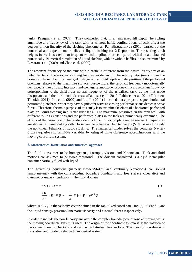
The resonant frequency of the tank with a baffle is different from the natural frequency of an
unbaffled tank. The resonant sloshing frequencies depend on the solidity ratio (unity minus the
porosity), the number of submerged plate gaps, the liquid depth, and the position of the perforated
openings relative to the mean free surface. Furthermore, the resonant frequency monotonically
decreases as the solid rate increases and the largest amplitude response is at the resonant frequency
corresponding to the third-order natural frequency of the unbaffled tank, as the first mode
disappeares and the third mode decreases(Faltinsen et al. 2010; Faltinsen et al. 2011; Faltinsen,
Timokha 2011). Liu et al. (2007) and Liu, Li (2011) indicated that a proper designed horizontal
perforated plate breakwater may have significant wave absorbing performance and decrease wave
forces. Therefore, the main purpose of this study is to examine the effect of a horizontal perforated
plate on liquid sloshing in a rectangular tank. The maximum pressures on the tank wall with
different rolling excitations and the perforated plates in the tank are numerically examined. The
effects of the porosity and the relative depth of the horizontal plate on the resonant frequencies
are shown. A numerical algorithm based on the volume of fluid technique (VOF) is used to study
the non-linear behavior of liquid sloshing. The numerical model solves the complete Navier-
Stokes equations in primitive variables by using of finite difference approximations with the
moving coordinate system.
2. Mathematical formulation and numerical approach
The fluid is assumed to be homogenous, isotropic, viscous and Newtonian. Tank and fluid
motions are assumed to be two-dimensional. The domain considered is a rigid rectangular
container partially filled with liquid.
The governing equations (namely Navier-Stokes and continuity equations) are solved
simultaneously with the corresponding boundary conditions and free surface kinematics and
dynamic boundary conditions in the fluid domain.
0),( vuU (1)
UFPUUU 21
t
(2)
where ),( vuU is the velocity vector defined in the tank fixed coordinate, and , P, and F are
the liquid density, pressure, kinematic viscosity and external forces respectively.
In order to include the non-linearity and avoid the complex boundary conditions of moving walls,
the moving coordinate system is used. The origin of the coordinate system is at the position of
the center plane of the tank and on the undisturbed free surface. The moving coordinate is
translating and rotating relative to an inertial system.

6 H.AKYILDIZ
GiDB|DERGi Sayı 9, 2017
The external force consists of gravitational forces, the translational and rotational inertia forces,
which can be written as,
rΩΩrΩ
VΩV
gF td
d
td
d2 (3)
where ΩVg and, are the gravitational vector, the translational velocity and the rotational
velocity vector. In addition, is the position vector of the considered point relative to O. On the
free surface, both the kinematic and dynamic conditions should be satisfied:
0)(
z
t
U
(4)
P = Patm (5)
where represents the free surface profile and Patm is the air pressure or ullage pressure inside
the tank. The surface tension is ignored in this study. Therefore, a no-shear is needed on the free
surface. But, proper wall conditions are necessary on the tank walls and the internal members.
2.1 Numerical Computation
For the analysis of the sloshing flow inside a partial filled tank, a finite difference method is
applied to the governing equations. A FDM (finite difference method) is useful when there are
internal structures inside the tank or the fluid contacts the tank ceiling frequently. As the internal
structures exist, the viscous effects may be dominant. In this study, the method concentrates on
the global fluid motion, so some local effects, such as turbulence and wave breaking have been
ignored. In some cases, these local effects are important, but the simulation of global flow plays
a more critical role in many sloshing problems.
The scheme adopted in this study is the SOLA method (Hirt, Nichols 1981). Tank volume is
discredited into Cartesian staggered grid cells. The mesh region containing fluid is composed of
cells and a single layer of fictitious cells (or boundary cells) surrounds the fluid region. The
fictitious cells are used to set the boundary conditions so that the same difference equation can be
used in the interior of the mesh.
Fluid velocities are located at the centers of the cell boundaries and pressure (P) and the volume
of fluid function (S) are computed at the center of the cell. The volume of fluid function is
governed by the Eulerian form of the transport equation in two dimensions. It can be formed by
using the incompressible version of the continuity equation.
0
SS
Sv
yu
xt
(6)
The volume of fluid function can be defined whose value is unity at any point occupied by fluid
and zero otherwise. The average value of (S) in a cell would represent the fractional volume of
the cell occupied by fluid. A unit value of (S) would correspond to a cell full of fluid, while a zero
value would indicate that the cell contained no fluid. Cells with (S) values between zero and one
must then contain a free surface. The solution algorithm works as a time cycle or ‘movie frame’.
SLOSHING IN A RECTANGULAR STORAGE TANK
WITH A HORIZONTAL PERFORATED PLATE
7
Sayı 9, 2017 GiDB|DERGi
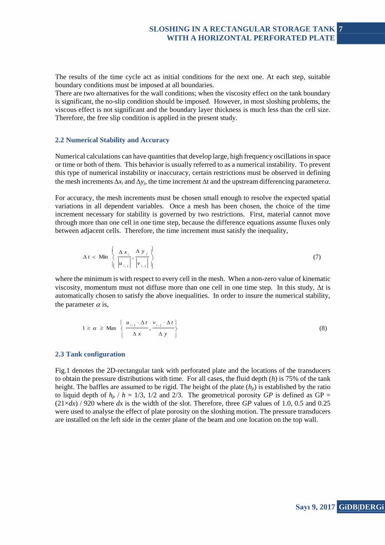
The results of the time cycle act as initial conditions for the next one. At each step, suitable
boundary conditions must be imposed at all boundaries.
There are two alternatives for the wall conditions; when the viscosity effect on the tank boundary
is significant, the no-slip condition should be imposed. However, in most sloshing problems, the
viscous effect is not significant and the boundary layer thickness is much less than the cell size.
Therefore, the free slip condition is applied in the present study.
2.2 Numerical Stability and Accuracy
Numerical calculations can have quantities that develop large, high frequency oscillations in space
or time or both of them. This behavior is usually referred to as a numerical instability. To prevent
this type of numerical instability or inaccuracy, certain restrictions must be observed in defining
the mesh increments xi and yj, the time increment t and the upstream differencing parameter.
For accuracy, the mesh increments must be chosen small enough to resolve the expected spatial
variations in all dependent variables. Once a mesh has been chosen, the choice of the time
increment necessary for stability is governed by two restrictions. First, material cannot move
through more than one cell in one time step, because the difference equations assume fluxes only
between adjacent cells. Therefore, the time increment must satisfy the inequality,
ji
j
ji
i
v
y
u
xt
,,
,Min (7)
where the minimum is with respect to every cell in the mesh. When a non-zero value of kinematic
viscosity, momentum must not diffuse more than one cell in one time step. In this study, t is
automatically chosen to satisfy the above inequalities. In order to insure the numerical stability,
the parameter is,
y
tv
x
tujiji ,,
,Max1 (8)
2.3 Tank configuration
Fig.1 denotes the 2D-rectangular tank with perforated plate and the locations of the transducers
to obtain the pressure distributions with time. For all cases, the fluid depth (h) is 75% of the tank
height. The baffles are assumed to be rigid. The height of the plate (hp) is established by the ratio
to liquid depth of hp / h = 1/3, 1/2 and 2/3. The geometrical porosity GP is defined as GP =
(21×dx) / 920 where dx is the width of the slot. Therefore, three GP values of 1.0, 0.5 and 0.25
were used to analyse the effect of plate porosity on the sloshing motion. The pressure transducers
are installed on the left side in the center plane of the beam and one location on the top wall.

8 H.AKYILDIZ
GiDB|DERGi Sayı 9, 2017
Fig. 1. Schematic diagram of the perforated plate configuration
Present numerical code is set up to handle a simple harmonic forcing function. Thereafter, it
advances the velocities in time explicitly using the two momentum equations. First, the angular
displacement and its derivatives are calculated. The apparent acceleration terms are then
calculated and finally the advective, diffusion and pressure gradients terms are calculated yielding
an estimate of the velocity at the new time level. The tank motion is the pitch oscillations about
y-axis only which follows the sinusoidal function given as )sin(0
t where θ0 and ω are the
rolling amplitude and the frequency, respectively. The rolling amplitude is chosen as 20 and 40 in
this study. The tank natural frequencies are calculated as follows (Lamb 1932):
5.0
tanh
h
L
i
L
igi
i = 1, 2, 3... (13)
where ωi is the natural frequency, and g is the gravitational acceleration. Faltinsen et al. [21]
indicated that a vertical perforated plate to a water tank may remove the first-order resonant
frequency. Thus, the first-order and the higher-order resonant frequencies are considered when
studying the resonant effect of sloshing.
When the period and amplitude of excitation are large, the liquid responds violently and causes
the numerical solution to become unstable. The instability are related to the instability of the fluid
motion, such as the occurrence of turbulence, wave breaking and the transition from homogeneous
flow to a two-phase flow. For these situations, the present numerical model is limited to the period
prior to the inception of these flow perturbations. On the other hand, in this study, to estimate the
h
hp
Wave probe
T3
T2
T1
T4
9.6 cm
39 cm
6 cm
6 cm
D=62 cm
L=92 cm
Transducer
6 cm

SLOSHING IN A RECTANGULAR STORAGE TANK
WITH A HORIZONTAL PERFORATED PLATE
9
Sayı 9, 2017 GiDB|DERGi
limited impact pressure on the tank top and to demonstrate the capability of the numerical code
in computing impact-type loads, the slosh of liquid at 75% fill depth with the rolling amplitudes
20 and 40 are chosen for all cases.
3. Results and discussions
3.1 Maximum pressures at different excitation frequencies
Fig. 2, at T1, denotes the non-dimensionless maximum pressures at different excitation
frequencies . It is obvious that the maximum pressure increases based on the time history of the
pressures for the unbaffled tank. The resonant effect on the maximum pressure occurs near the
natural frequency.
Fig. 2. Maximum pressures for an un-baffled tank at T1.
On the other hand, the resonant effect on the maximum pressures at other frequencies are very
small. Since the transducer of T2 locates near the initial free surface height, the values of pressure
are obtained by net liquid impact, resulting in the dynamic pressures (Fig. 3).
It can be concluded that the static pressure is mainly predominant over the dynamic pressure as
the rolling frequency increases continuously. Additionally, the maximum pressure at T2 is
increased near the first-order resonant frequency due to the net impact loads. Figs. 4-9, at T1, also
indicate that the horizontal perforated plate with hP / h = 2/3, 1/2 , 1/3 and GP = 0.25 does not
change the resonant frequency significantly. Because, small porosity with the relative submerged
depth represents the shallow water effects and the free surface behavior is getting stable slowly
due to the inertial forces. On the other hand, as shown in Figs. 10-15, at T2, the horizontal
perforated plate shows that the natural frequency is more influenced by the plates for first-order
mode than the higher-order modes.
As shown in Figs. 4-9 and Figs. 10-15, among all cases, the maximum pressures at hP / h = 1/3
with GP = 0.25 are the smallest for the rolling amplitudes of 40 and 20. Therefore, it is indicated
that a suppression effect could be obtained by adjusting either the location or geometric porosity
of the horizontal perforated plate. The maximum pressures at T1 do not change very much for
other modes of the natural frequencies comparing to the first-order mode when hP / h = 1/3 and

10 H.AKYILDIZ
GiDB|DERGi Sayı 9, 2017
GP = 0.25. On the other hand, the maximum pressures at T2 change much more for other modes
of the natural frequencies due to the net liquid impact. It is indicated that the porosity influences
the maximum pressure, and the relative submerged depth changes the period.
Fig. 3. Maximum pressures for an un-baffled tank at T2.
Fig. 4. Maximum pressures at T1. θ0 = 40 ; hP / h = 2/3.

SLOSHING IN A RECTANGULAR STORAGE TANK
WITH A HORIZONTAL PERFORATED PLATE
11
Sayı 9, 2017 GiDB|DERGi
Fig. 5. Maximum pressures at T1. θ0 = 40 ; hP / h = 1/2.
Fig. 6. Maximum pressures at T1. θ0 = 40 ; hP / h = 1/3.
Fig. 7. Maximum pressures at T1. θ0 = 20 ; hP / h = 2/3.
Fig. 8. Maximum pressures at T1. θ0 = 20 ; hP / h = 1/2.

12 H.AKYILDIZ
GiDB|DERGi Sayı 9, 2017
Fig. 9. Maximum pressures at T1. θ0 = 20 ; hP / h = 1/3.
3.2 The influence factors of the sloshing loads
It can be said that the horizontal perforated plate is useful for restraining the free surface
elevations and thereafter the sloshing loads. For the rolling amplitudes of 40 and 20, the
maximum pressures at T1 and T2 decrease with the smaller plate porosity near the first-order
resonant frequency. This reduction is also more significant at a smaller relative submerged
depth of hP / h = 1/3. Additionally, the resonant frequency is shifted by the horizontal perforated
plate at the higher order modes when the plate submerged depth is getting smaller. It is
indicated that the relative submerged depth is of great importance in the control of the sloshing
loads at a higher mode. It can be recommended that a horizontal perforated plate with smaller
porosity is effective for reducing resonant sloshing in a liquid tank. The results also show that
the variations at the first-order mode have a trend of moving away diminishingly from the
natural frequency with a decrease of porosity and relative submerged depth.
The maximum pressures decrease monotonously with the decrease of GP and hP / h while the
larger pressures appear at the lower mode. This means that the resonant sloshing at the lower
mode can be restrained by a horizontal perforated plate with a small porosity and a small
relative submerged depth. Furthermore, it suppresses slightly the liquid sloshing because of the
hydrodynamic damping and the blockage effects. Then, the rolling motion of the liquid becomes
weaker and free surface behavior is getting stable by the shallow water effects. It can be
indicated that the effect of restriction is obvious for the first-order mode.
It can also be said that the value of the maximum pressure keeps increasing as hP / h and the
rolling frequencies increase. It is of great importance to know the maximum pressure exerting
on the tank wall in the design of the liquid tanks. Thus, the instantaneous peak values in the time
histories of the pressure at each transducer have been averaged to obtain the mean maximum
pressure according to the height of the perforated plate. Since the transducer of T2 locates near
the initial free surface height, the values of pressure are obtained by net liquid impact, resulting
in the dynamic pressures. As the rolling amplitude decreases continuously, the maximum
pressures decrease. In general, at T1, the static pressure is mainly predominant over the dynamic
pressure while the dynamic pressure is mainly predominant over the static pressure at T2.

SLOSHING IN A RECTANGULAR STORAGE TANK
WITH A HORIZONTAL PERFORATED PLATE
13
Sayı 9, 2017 GiDB|DERGi
Fig. 10. Maximum pressures at T2. θ0 = 40 ; hP / h = 2/3.
Fig. 11. Maximum pressures at T2. θ0 = 40 ; hP / h = 1/2.

14 H.AKYILDIZ
GiDB|DERGi Sayı 9, 2017
Fig. 12. Maximum pressures at T2. θ0 = 40 ; hP / h = 1/3.
Fig. 13. Maximum pressures at T2. θ0 = 20 ; hP / h = 2/3.
Fig. 14. Maximum pressures at T2. θ0 = 20 ; hP / h = 1/2.
Fig. 15. Maximum pressures at T2. θ0 = 20 ; hP / h = 1/3.

SLOSHING IN A RECTANGULAR STORAGE TANK
WITH A HORIZONTAL PERFORATED PLATE
15
Sayı 9, 2017 GiDB|DERGi
4. Conclusions
In this study, the effectiveness and characteristics of the tank have been investigated numerically
with different horizontal perforated plates under different excitation amplitudes and frequencies
in a moving partially filled 2D-ractangular tank. The present study is limited to the frequency
prior to the inception of flow perturbations such as turbulence and two-phase flow considering
the global sloshing loads. The horizontal perforated plates are useful for restraining violent
sloshing effects in a rectangular tank under rolling excitation. The characteristics of the tank with
a horizontal perforated plate showed that the natural frequency is more influenced by the plates
for first-order mode than the higher-order modes. Thus, the characteristics of this tank system
offers a large damping effect to reduce the sloshing loads, ensuring that the tank resonant sloshing
could be activated by the natural frequency and dissipate energy significantly.
In the numerical calculations, GP = 0.25 and hp / h = 1/3 are the best choice. Moreover, as a
general conclusion, the plates need to be placed under the water surface to ensure proper activity
and the better the restraining effect it can offer. The total area of the perforations should be
determined by taking into account the strength of the plates in drilling the slots.
The effect on the maximum pressure at the excitation frequencies away from the first-order mode
is small. It has an obvious variation of the maximum pressure that is decreased when GP
decreases. The maximum pressure, at T1, increases and is greater than the unbaffled tank at the
first-order resonance. Furthermore, the maximum pressure, at T2, increases and is greater than
the unbaffled tank when hp / h = 1/2 and hp / h = 1/3 especially for GP = 0.5.
The numerical calculations showed that the amplitude of excitation, the intensity of nonlinearity
and the sloshing damping influenced the frequency responeses in different ways. But the
amplitude of excitation played a much more role in affecting the sloshing motion than the other
factors. To be more precisely, the amplitude of excitation influences greatly on the sloshing
phenomenon and the maximum pressure by increasing or decreasing the amplitudes of sloshing
motion.
Kaynaklar:
Akyildiz H, Unal NE (2005) Experimental investigation of pressure distribution on a rectangular
tank due to the liquid sloshing, Ocean Engineering 32 1503-1516.
Akyildiz H, Unal NE (2006) Sloshing in a three dimensional rectangular tank: Numerical
simulation and experimental validation, Ocean Engineering 33(16) 2135-2149.
Akyildiz H (2012) A numerical study of the effect of the vertical baffle on liquid sloshing in two-
dimensional rectangular tank, Journal of Sound and Vibration 331 41-52.
Akyıldız H, Unal NE, Aksoy H (2013). An experimental investigation of the effects of the ring
baffles on liquid sloshing in a rigid cylindrical tank. Ocean Engineering, 59,190-197.
Biswal KC, Bhattacharyya SK, Sinha PK (2004) Dynamic response analysis of a liquid-filled
cylindrical tank with annular baffle, Journal of Sound and Vibration 274 13–37.

16 H.AKYILDIZ
GiDB|DERGi Sayı 9, 2017
Chen YG, Djidjeli K, Price WG (2009) Numerical simulation of liquid sloshing phenomena in
partially filled containers. Computers and Fluids 38 830– 842.
Eswaran M, Saha UK, Maity D (2009) Effect of baffles on a partially filled cubic tank: Numerical
simulation and experimental validation, Computers and Structures 87 198– 205.
Faltinsen OM, Firoozkoohi R, Timokha AN (2010) Analytical modeling of liquid sloshing in a
two-dimensionless rectangular tank with a slat screen, Journal of Engineering Mathematics. 70
93–109.
Faltinsen OM, Firoozkoohi R, Timokha AN (2011) Steady-state liquid sloshing in a rectangular
tank with a slat-type screen in the middle: Quasilinear modal analysis and experiments, Physics
of Fluids 23 042101.
Faltinsen OM, Timokha AN (2011) Natural sloshing frequencies and modes in a rectangular tank
with a slat-type screen, Journal of Sound and Vibration 330 1490–1503.
Gavrilyuk I, Lukovsky I, Trotsenko Y, Timokha A (2006) Sloshing in a vertical circular
cylindrical tank with an annular baffle. Part 1. Linear fundamental solutions. Journal of
Engineering Mathematics, 54, 1:71-88.
Goudarzi MA, Sabbagh-Yazdi SR (2012) Analytical and experimental evaluation on the
effectiveness of upper mounted baffles with respect to commonly used baffles. Ocean Eng. 42,
205–217
Hasheminejad SM, Mohammadi MM, Jarrahi M (2014) Liquid sloshing in partly-filled laterally-
excited circular tanks equipped with baffles. Journal of Fluids and Structures, 44, 97-114.
Hirt CW, Nichols BD (1981) Volume of fluid (VOF) method for the dynamics of free boundaries,
Journal of Computational Physics 39 201– 225.
Ibrahim RA (2005), Liquid Sloshing Dynamics: Theory and Applications. Cambridge University
Press, New York.
Jung JH, Yoon HS, Shin SC (2012) Effect of the vertical baffle height on the liquid sloshing in a
three-dimensional rectangular tank, Ocean Engineering 44 79-89.
Lamb H (1932) Hydrodynamics. Cambridge University Press, Cambridge, UK.
Liu Y, Li Y, Teng B (2007) Wave interaction with a perforated wall breakwater with a submerged
horizontal porous baffle, Ocean Engineering 34 2364–2373.
Liu D, Lin P (2009) A numerical study of three-dimensional liquid sloshing in tanks, Ocean
Engineering 36 202–212.
Liu Y, Li Y (2011) An alternative analytical solution for water-wave motion over a submerged
horizontal porous baffle, Journal of Engineering Mathematics 69 385–400.
Maleki A, Ziyaeifar M (2008) Sloshing damping in cylindrical liquid storage tanks with baffles.
Journal of Sound and Vibration, 311, 372-385.

SLOSHING IN A RECTANGULAR STORAGE TANK
WITH A HORIZONTAL PERFORATED PLATE
17
Sayı 9, 2017 GiDB|DERGi
Nayak SK, Biswal KC (2015) Fluid damping in rectangular tank fitted with various internal
objects – An experimental investigation. Ocean Engineering, 108, 552-562.
Pal P, Bhattacharyya SK (2010) Sloshing in partially filled liquid containers – Numerical and
experimental study for 2-D problems, Journal of Sound and Vibration 329 4466-4485.
Panigrahy PK, Saha UK, Maity D (2009) Experimental studies on sloshing behavior due to
horizontal movement of liquids in baffled tanks, Ocean Engineering 36(3-4) 213-222.
Wang JD, Lo SH, Zhou D (2013) Sloshing of liquid in rigid cylindrical container with multiple
rigid annular baffles: Lateral excitations. Journal of Fluids and Structures,42, 421-436.
Wu CH, Faltinsen OM, Chen BF (2013) Time-Independent Finite Difference and Ghost Cell
Method to Study Sloshing Liquid in 2D and 3D Tanks with Internal Structures, Computational
Physics 13 780–800
Xue MA, Zheng JH, Lin PZ (2012) Numerical simulation of sloshing phenomena in cubic tank
with multiple baffles, Journal of Applied Mathematics, Article ID 245702.
Xue MA, Lin PZ, Zheng JH, Ma YX, Yuan XL, Nguyen VT (2013) Effects of perforated baffle
on reducing sloshing in rectangular tank: Experimental and numerical study. China Ocean
Engineering, 27, 5, 615-628.
Zheng JH, Kargbo O, Yuan XL, Xue MA, Lin PZ (2013) An experimental study of nonlinear
liquid sloshing in a rectangular tank. Proceedings of the 23rd International Offshore and Polar
Engineering Conference, 171-177

18 H.AKYILDIZ
GiDB|DERGi Sayı 9, 2017