SLOPE STABILITY REPORT - 2016 GORTADROMA … · Section 1 Limerick City and County Council Slope...
16
SLOPE STABILITY REPORT - 2016 GORTADROMA LANDFILL, CO. LIMERICK WASTE LICENCE W0017-04 ORIGINAL NOVEMBER 2016 For inspection purposes only. Consent of copyright owner required for any other use. EPA Export 07-02-2017:02:08:23
Transcript of SLOPE STABILITY REPORT - 2016 GORTADROMA … · Section 1 Limerick City and County Council Slope...

SLOPE STABILITY REPORT - 2016
GORTADROMA LANDFILL, CO. LIMERICK
WASTE LICENCE W0017-04
ORIGINAL
NOVEMBER 2016
For
insp
ectio
n pur
pose
s only
.
Conse
nt of
copy
right
owne
r req
uired
for a
ny ot
her u
se.
EPA Export 07-02-2017:02:08:23

LW15/842/02/Reports/Rpt001.doc
SLOPE STABILITY REPORT - 2016
GORTADROMA LANDFILL, CO. LIMERICK
WASTE LICENCE W0017-04
User is Responsible for Checking the Revision Status of This Document
Rev.
Nr.
Description of
Changes
Prepared
by:
Checked by: Approved
by:
Date:
0 Issue to Client TC JD BG 22.11.2016
Client: Limerick City and County Council
Keywords: Gortadroma, landfill, capping, slope stability, waste licence W0017-04
Abstract: This slope stability report was prepared in order to comply with the waste licence.
Analyses of global rotational slip failures of the waste slopes are presented.
For
insp
ectio
n pur
pose
s only
.
Conse
nt of
copy
right
owne
r req
uired
for a
ny ot
her u
se.
EPA Export 07-02-2017:02:08:23

i/ii
TABLE OF CONTENTS
PAGE
1. INTRODUCTION ............................................................................................................................................1
1.1. PURPOSE .................................................................................................................................................1 1.2. SITE DESCRIPTION ....................................................................................................................................1 1.3. SLOPE STABILITY ANALYSIS METHOD .........................................................................................................3 1.4. LIMITATIONS OF SLOPE STABILITY ANALYSIS ..............................................................................................3 1.5. FACTORS CONTROLLING THE STABILITY OF LANDFILL SLOPES .....................................................................3
2. DESIGN CRITERIA ........................................................................................................................................4
2.1. SLOPE GEOMETRY ....................................................................................................................................4 2.2. GEOLOGY .................................................................................................................................................4 2.3. FACTORS OF SAFETY ................................................................................................................................5 2.4. PHYSICAL MAKE-UP ..................................................................................................................................5 2.5. WASTE PARAMETERS ................................................................................................................................5 2.6. PROPERTIES OF THE SUPPORTING SOIL AND CAPPING LAYER .....................................................................7 2.7. GROUNDWATER LEVELS WITHIN THE WASTE MATERIAL ...............................................................................7 2.8. SURCHARGE .............................................................................................................................................8
3. RESULTS .......................................................................................................................................................9
3.1. SLOPE STABILITY ANALYSES ......................................................................................................................9 3.2. MODEL RESULTS ......................................................................................................................................9
4. DISCUSSION AND CONCLUSIONS .......................................................................................................... 11
5. REFERENCES ............................................................................................................................................ 12
For
insp
ectio
n pur
pose
s only
.
Conse
nt of
copy
right
owne
r req
uired
for a
ny ot
her u
se.
EPA Export 07-02-2017:02:08:23

ii/ii
LIST OF TABLES
PAGE
Table 2.1: Characteristic Parameters for Waste Materials .............................................................. 5 Table 2.2: Partial Factors Used to Derive Design Parameters ........................................................ 6 Table 2.3: Design Parameters for Waste Materials ........................................................................ 7 Table 2.4: Characteristic Parameters for Supporting Materials ....................................................... 7 Table 2.5: Design Parameters for Supporting Materials ................................................................. 7 Table 3.1: Slope Analysis Results – Using Parameters for Fresh Waste ........................................ 9
LIST OF FIGURES
Figure 1: Landfill Sections ................................................................................................................... 4 Figure 3.1: Typical slope failure for Section A-A (Morgensten-Price Method) for Leachate Level of 106 m AOD. .................................................................................................................................... 10
For
insp
ectio
n pur
pose
s only
.
Conse
nt of
copy
right
owne
r req
uired
for a
ny ot
her u
se.
EPA Export 07-02-2017:02:08:23

Section 1 Limerick City and County Council Slope Stability Report
Gortadroma Landfill – Waste Licence W0017-04
Page 1 of 11
1. INTRODUCTION
1.1. Purpose This report presents the results of a slope stability assessment carried out for Gortadroma Landfill in
October / November 2016. This is in accordance with the EPA waste licence W0017-04 issued to the site.
1.2. Site Description Gortadroma Landfill is operated by Limerick City and County Council. The site is located approximately 8 km south of the Shannon Estuary, approximately 12km north of Newcastle West, between the villages of Ardagh and Shanagolden. The topography in the vicinity of the landfill is undulating with former elevations of between 100 m and
132 m OD across the landfill. Landfill operations ceased on site in April 2014 and the installation of the
landfill cap was completed in August 2014. A site walkover was made by a Geotechnical Engineer from Fehily Timoney and Company in October 2016. The walkover included an inspection of all capped areas of the site in order to identify any particularly steep slopes or areas of potential instability. A toe bulge was noted in the south-western corner of the site (see Photo 4) which was considered to be due
to irregular placing of waste during the construction of the heap. No further signs of instability (such as tension cracking or the formation of a backscarp) were noted at the site. No visibly unstable slopes were observed on the site and no tension cracks were observed in any of the slopes which may have suggested potential instability. Some ponding was noted in two areas of the site (Photo 5 and 6), particularly to the north and east of the eastern waste heap which showed signs of
established long-term ponding of water.
The steepest slopes on the site were observed as being within the most recently filled and recently capped areas, within the eastern part of the landfill (Photo 3 and 6). These slopes were therefore selected for subsequent numerical analysis.
For
insp
ectio
n pur
pose
s only
.
Conse
nt of
copy
right
owne
r req
uired
for a
ny ot
her u
se.
EPA Export 07-02-2017:02:08:23

Section 1 Limerick City and County Council Slope Stability Report
Gortadroma Landfill – Waste Licence W0017-04
Page 2 of 11
Photo 1: Shallow Slopes on West side of “Old” Cells Photo 2: Hydrophilic Vegetation on Northern Face of “Old” Cells
Photo 3: Western Slope of “New” Cells Photo 4: Slight Bulge in South-West corner of “Old” Cells – likely original slope profile (no signs of instability)
Photo 5: Ponding at toe of slope on north side of “New” cells
Photo 6: Ponding on east side of “New” Cells with typical stable slope to right of photo
For
insp
ectio
n pur
pose
s only
.
Conse
nt of
copy
right
owne
r req
uired
for a
ny ot
her u
se.
EPA Export 07-02-2017:02:08:23

Section 1 Limerick City and County Council Slope Stability Report
Gortadroma Landfill – Waste Licence W0017-04
Page 3 of 11
1.3. Slope Stability Analysis Method SLOPE/W software of GEO-SLOPE International Ltd. was used to assess the stability of Gortadroma Landfill. SLOPE/W is a general software tool for the slope stability analysis of earth structures. It uses the limit equilibrium method of analysis by using the idea of dissecting a potential sliding mass into vertical slices. It assesses the factor of safety for both moment and force equilibrium based on various methods, including Bishop, Janbu and Morgenstern-Price.
Using this software, it is possible to deal with complex stratigraphy, highly irregular pore-water pressure conditions, a variety of linear and nonlinear shear strength models, virtually any kind of slip surface shape, concentrated loads and pressure lines. Limit equilibrium formulations based on the method of slices are also being applied more and more to the stability analysis of structures such as tieback walls, nail or fabric reinforced slopes, and even the sliding stability of structures subjected to high horizontal loading arising.
Traditionally, the factor of safety is defined as that factor by which the shear strength of the soil must be reduced in order to bring the mass of soil into a state of limiting equilibrium along a selected slip surface.
The results of the analysis show the overall stability of the embankment expressed as a factor of safety. The definition of factor of safety used within SLOPE/W is:
forces)(or moment disturbing Total
forces)(or moment restoring AvailableF
Design values for use in the slope stability analysis have been derived using Eurocode 7 (IS EN 1997-1) Design Approach 3. This design approach is considered to be the most logical approach for slope stability analysis as it includes partial factors for both material properties and variable loads (for example traffic loads).
1.4. Limitations of Slope Stability Analysis Updated shear strength parameters for the landfill waste has been estimated based on parameters used by
Kolsch (1995). Groundwater or leachate in landfills may occur in irregular perched bodies as opposed to interconnected liquid bodies. For the purposes of this analysis, the leachate level has been assumed as the highest level typically maintained by pumping during 2015.
1.5. Factors Controlling the Stability of Landfill Slopes The factors controlling the stability of landfill slopes are:
Slope geometry
Geology
Properties of the landfill wastes
Properties of the supporting soil
Groundwater/leachate levels within the waste
Groundwater levels in the supporting soil
Surcharge.
For
insp
ectio
n pur
pose
s only
.
Conse
nt of
copy
right
owne
r req
uired
for a
ny ot
her u
se.
EPA Export 07-02-2017:02:08:23
Section 2 Limerick City and County Council Slope Stability Report
Gortadroma Landfill – Waste Licence W0017-04
Page 4 of 11
2. DESIGN CRITERIA
2.1. Slope Geometry
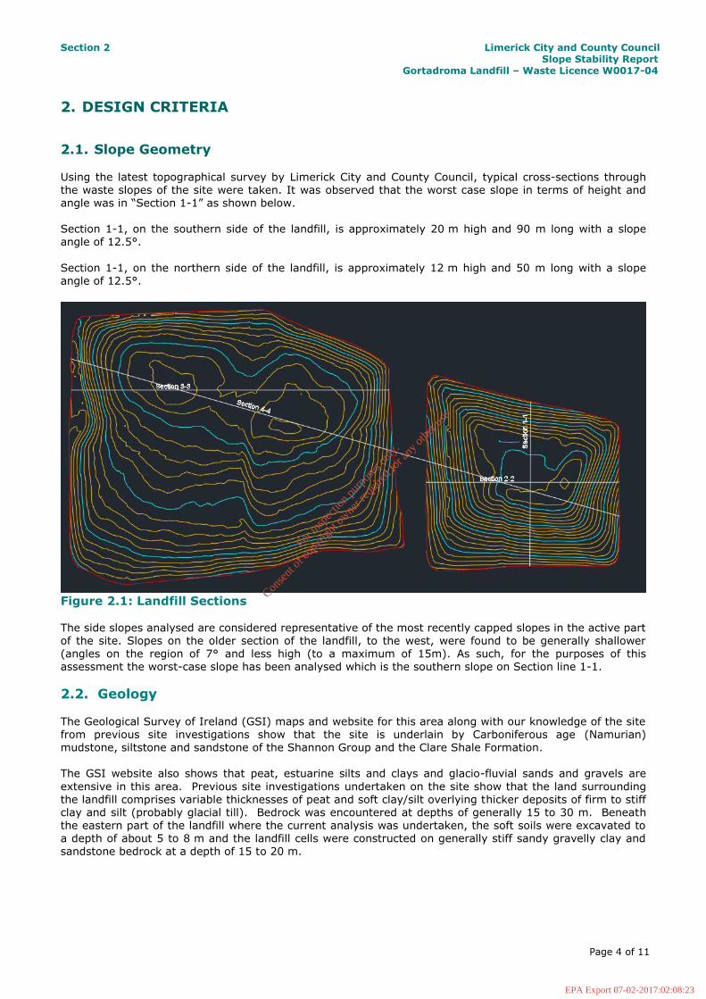
Using the latest topographical survey by Limerick City and County Council, typical cross-sections through the waste slopes of the site were taken. It was observed that the worst case slope in terms of height and angle was in “Section 1-1” as shown below. Section 1-1, on the southern side of the landfill, is approximately 20 m high and 90 m long with a slope angle of 12.5°.
Section 1-1, on the northern side of the landfill, is approximately 12 m high and 50 m long with a slope angle of 12.5°.
Figure 2.1: Landfill Sections
The side slopes analysed are considered representative of the most recently capped slopes in the active part of the site. Slopes on the older section of the landfill, to the west, were found to be generally shallower (angles on the region of 7° and less high (to a maximum of 15m). As such, for the purposes of this assessment the worst-case slope has been analysed which is the southern slope on Section line 1-1.
2.2. Geology The Geological Survey of Ireland (GSI) maps and website for this area along with our knowledge of the site from previous site investigations show that the site is underlain by Carboniferous age (Namurian)
mudstone, siltstone and sandstone of the Shannon Group and the Clare Shale Formation. The GSI website also shows that peat, estuarine silts and clays and glacio-fluvial sands and gravels are
extensive in this area. Previous site investigations undertaken on the site show that the land surrounding the landfill comprises variable thicknesses of peat and soft clay/silt overlying thicker deposits of firm to stiff clay and silt (probably glacial till). Bedrock was encountered at depths of generally 15 to 30 m. Beneath the eastern part of the landfill where the current analysis was undertaken, the soft soils were excavated to a depth of about 5 to 8 m and the landfill cells were constructed on generally stiff sandy gravelly clay and sandstone bedrock at a depth of 15 to 20 m.
For
insp
ectio
n pur
pose
s only
.
Conse
nt of
copy
right
owne
r req
uired
for a
ny ot
her u
se.
EPA Export 07-02-2017:02:08:23

Section 2 Limerick City and County Council Slope Stability Report
Gortadroma Landfill – Waste Licence W0017-04
Page 5 of 11
2.3. Factors of Safety
In accordance with the principals of Eurocode 7 (IS EN 1997-1), rather than using a global factor of safety as per previous design codes, the factors of safety (termed partial factors) are applied to the chosen characteristic values to obtain design values. Actions (influences) are multiplied by the safety factor, while resistances are divided by the safety factor. In accordance with Eurocode 7 (IS EN 1997-1), geotechnical checks must be carried out to ensure that the resistance preventing a slide are greater than or equal to the actions which cause a slide, i.e.:
Ed <= Rd Where: Ed = Sum of design actions
Rd = Sum of design resistances
By adopting the methods of analysis given in Eurocode 7 (IS EN 1997-1), the factor of safety against failure is included in the partial factors (ranging from 1.0 to 1.3 for various parameters) applied to the analysis rather than to the end result. In order to verify that this condition is met, the resulting “safety ratio” must be equal or greater than 1.0 in order to verify that the above condition is met. i.e.: An in-situ ”safety ratio”
of less than 1.0 indicates that the slope currently has an inadequate factor of safety against failure and therefore is potentially unstable. Ratios greater than 1.0 indicate an adequate factor of safety against failure and are considered stable in both short and long term.
2.4. Physical Make-up The slopes considered for analyses are assumed to consist of the following layers, as derived for previous slope analyses on the site:
Approximately 1.0 m layer of cohesive subsoil/topsoil capping material
Waste body comprising of landfill waste
0.5 to 1.0 m bentonite clay lining
Underlying glacial till and bedrock (the soft clays and silts were excavated during construction of the landfill cells)
2.5. Waste Parameters Table 2.1 below shows the parameters used for the landfill waste materials.
Table 2.1: Characteristic Parameters for Waste Materials
Material Waste
(Old)
Waste
(Fresh)
Cohesion (c’) 10 kN/m2 10 kN/m2
Effective friction angle (’)
22˚ 15˚
Unit weight 11 kN/m3 9.5 kN/m3
The parameters shown in Table 2.1 above are the typical range of values from published papers on the properties of waste. For the purpose of this analysis, the more conservative parameters for fresh waste have been used during the initial analysis.
For
insp
ectio
n pur
pose
s only
.
Conse
nt of
copy
right
owne
r req
uired
for a
ny ot
her u
se.
EPA Export 07-02-2017:02:08:23

Section 2 Limerick City and County Council Slope Stability Report
Gortadroma Landfill – Waste Licence W0017-04
Page 6 of 11
Table 2.2: Partial Factors Used to Derive Design Parameters
Set Partial Factor
Parameter
M2
γc' 1.25 Effective cohesion
γ' 1.25 Effective angle of friction
γγ 1 Soil density
A2 γQ 1.3 Traffic Loading (variable unfavourable)
R3 γR;e 1 Earth resistance
Table 2.2 shows the partial factors which have been applied to the characteristic values to give the derived parameters in Table 2.3 and 2.5 used during the slope stability analyses. The design parameter is derived by are multiplied or dividing the characteristic values by the associated partial factor, i.e. 15(’) / 1.25(γ')
= 12o.
For
insp
ectio
n pur
pose
s only
.
Conse
nt of
copy
right
owne
r req
uired
for a
ny ot
her u
se.
EPA Export 07-02-2017:02:08:23

Section 2 Limerick City and County Council Slope Stability Report
Gortadroma Landfill – Waste Licence W0017-04
Page 7 of 11
Table 2.3: Design Parameters for Waste Materials
Material
Waste
(Old)
Waste
(Fresh)
Cohesion (c’) 8 kN/m2 8 kN/m2
Effective friction angle (’)
17.6˚ 12˚
Unit weight 11 kN/m3 9.5 kN/m3
2.6. Properties of the Supporting Soil and Capping Layer Table 2.4 below shows the characteristic parameters used for the clay capping and the underlying strata. Table 2.5 shows the design parameters after applying the relevant partial factors in Table 2.2.
Table 2.4: Characteristic Parameters for Supporting Materials
Material Clay
Capping
Soft Clay
/Silt
Clay Liner
Glacial Till
Cohesion, c’, kN/m2
4 0 4 0
Friction angle, ’,
29 24 29 30
Bulk unit weight, ,
kN/m3 18 18 18 20
Table 2.5: Design Parameters for Supporting Materials
Material Clay
Capping
Soft
Clay/Silt
Clay
Liner
Glacial
Till
Cohesion, c’, kN/m2
3.2 0 3.2 0
Friction angle, ’,
23.2 19.2 23.2 24
Bulk unit weight, ,
kN/m3 18 18 18 20
2.7. Groundwater Levels within the Waste Material To model the effects of leachate within the waste body, a piezometric head of 1 m above the basal liner was used in the analysis. It is understood that the leachate level is generally maintained below this level by pumping of the leachate.
For
insp
ectio
n pur
pose
s only
.
Conse
nt of
copy
right
owne
r req
uired
for a
ny ot
her u
se.
EPA Export 07-02-2017:02:08:23

Section 2 Limerick City and County Council Slope Stability Report
Gortadroma Landfill – Waste Licence W0017-04
Page 8 of 11
2.8. Surcharge A modelled surcharge 20 kN/m2 was conservatively applied to the slopes during the analyses to simulate the movement of vehicles on the slopes. After applying a partial factor of 1.3 as per IS EN 1997-1 Design Approach 3 (variable, unfavourable action), a design load of 26 kN/m2 has been applied to the models. It should be noted that without applying this surcharge, the calculated factor of safety for the sections may also improve.
For
insp
ectio
n pur
pose
s only
.
Conse
nt of
copy
right
owne
r req
uired
for a
ny ot
her u
se.
EPA Export 07-02-2017:02:08:23

Section 3 Limerick City and County Council Slope Stability Report
Gortadroma Landfill – Waste Licence W0017-04
LW15/842/02/Reports/Rpt001.doc Page 9 of 11
3. RESULTS
3.1. Slope Stability Analyses Models were run on two representative sections to assess the slope stability of the landfill waste
embankments. The results of those analyses are summarised in Table 3.1 with safety ratios calculated for Bishop, Janbu and Morgenstern-Price methods. Table 3.1 also presents the material parameters applied, the groundwater level simulated, and the length and type of the relevant slip. The critical slope analysis is presented graphically for the slope in Figure 3.1 using the Morgernstern-Price method of analysis.
3.2. Model Results Safety ratios for potential slope failures (Table 3.1) for typical leachate levels ranged from 1.22 to 1.77.
Analyses were undertaken for both deep-seated (rotational) type slips and shallow (translational) type
although the deep rotational failures gave the lower safety ratios. It should be noted that the Janbu method is considered much more conservative than either the Bishop or Morgenstern Price methods.
Table 3.1: Slope Analysis Results – Using Parameters for Fresh Waste
Slope
name
Leachate
Level
(mAOD)
Morgen
stern-
Price
FoS
Bishop
FoS
Janbu
FoS
Slip
Length
(m)
Slip type & location
Section A-A
106.0 1.16 1.16 1.08 90 Deep rotational slip through clay capping and waste
In order to model the effect of degradation of the waste on the long term stability of the slopes, the models were also run using the published parameters for old waste. Generally, these parameters are used when the main body of landfill waste is greater than 7 or 8 years old which results in a greater safety ratio over time. Additionally, the waste body will consolidate, reducing the final slope profile and further increasing stability.
Table 3.2: Slope Analysis Results – Using Parameters for Old Waste
Slope
name
Leachate
Level
(mAOD)
Morgen
stern-
Price
FoS
Bishop
FoS
Janbu
FoS
Slip
Length
(m)
Slip type & location
Section
A-A
106.0 1.46 1.46 1.37 70 Deep rotational slip through
clay capping and waste
For
insp
ectio
n pur
pose
s only
.
Conse
nt of
copy
right
owne
r req
uired
for a
ny ot
her u
se.
EPA Export 07-02-2017:02:08:23

Section 3 Limerick City and County Council Slope Stability Report
Gortadroma Landfill – Waste Licence W0017-04
LW15/842/02/Reports/Rpt001.doc Page 10 of 11
1
2
34
5
6
1.156
Description: Clay Capping Wt: 18 Cohesion: 3.2 Phi: 23.2
Description: Waste Wt: 9.5 Cohesion: 8 Phi: 12
Description: Clay Liner Wt: 18 Cohesion: 3.2 Phi: 23.2
Description: Soft organic clay/silt Wt: 18 Cohesion: 0 Phi: 19.2
Description: Glacial Till Wt: 20 Cohesion: 0 Phi: 24
Description: Bedrock
Horizontal Distance (m)
0 10 20 30 40 50 60 70 80 90 100 110 120 130
Ele
va
tio
n (
mO
D)
80
85
90
95
100
105
110
115
120
125
130
135
Figure 3.1: Typical slope failure for Section A-A (Morgensten-Price Method) for Leachate Level of 106 m AOD.
For
insp
ectio
n pur
pose
s only
.
Conse
nt of
copy
right
owne
r req
uired
for a
ny ot
her u
se.
EPA Export 07-02-2017:02:08:23
Section 4 Limerick County Council Slope Stability Report
Gortadroma Landfill – Waste Licence W0017-04
LW15/842/02/Reports/Rpt001.doc Page 11 of 11
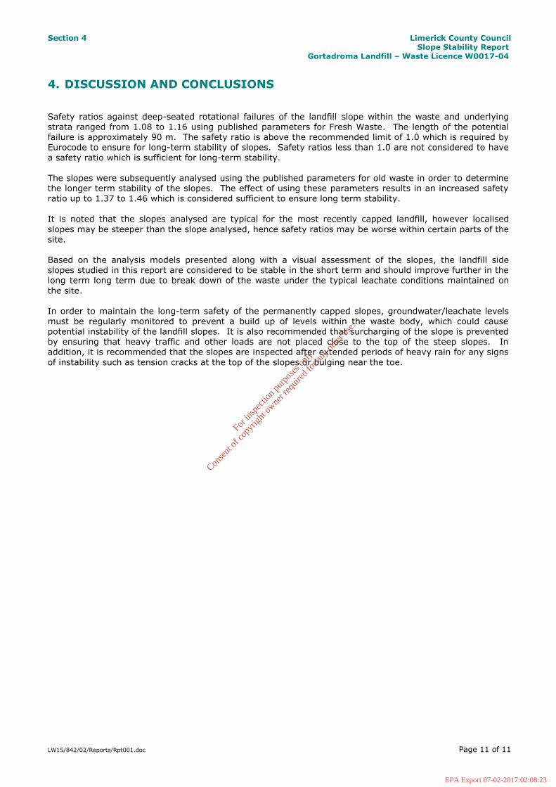
4. DISCUSSION AND CONCLUSIONS Safety ratios against deep-seated rotational failures of the landfill slope within the waste and underlying strata ranged from 1.08 to 1.16 using published parameters for Fresh Waste. The length of the potential failure is approximately 90 m. The safety ratio is above the recommended limit of 1.0 which is required by Eurocode to ensure for long-term stability of slopes. Safety ratios less than 1.0 are not considered to have
a safety ratio which is sufficient for long-term stability. The slopes were subsequently analysed using the published parameters for old waste in order to determine the longer term stability of the slopes. The effect of using these parameters results in an increased safety ratio up to 1.37 to 1.46 which is considered sufficient to ensure long term stability. It is noted that the slopes analysed are typical for the most recently capped landfill, however localised
slopes may be steeper than the slope analysed, hence safety ratios may be worse within certain parts of the site.
Based on the analysis models presented along with a visual assessment of the slopes, the landfill side slopes studied in this report are considered to be stable in the short term and should improve further in the long term long term due to break down of the waste under the typical leachate conditions maintained on
the site. In order to maintain the long-term safety of the permanently capped slopes, groundwater/leachate levels must be regularly monitored to prevent a build up of levels within the waste body, which could cause potential instability of the landfill slopes. It is also recommended that surcharging of the slope is prevented by ensuring that heavy traffic and other loads are not placed close to the top of the steep slopes. In addition, it is recommended that the slopes are inspected after extended periods of heavy rain for any signs
of instability such as tension cracks at the top of the slopes or bulging near the toe.
For
insp
ectio
n pur
pose
s only
.
Conse
nt of
copy
right
owne
r req
uired
for a
ny ot
her u
se.
EPA Export 07-02-2017:02:08:23

5. References
1. Kolsch (1995) Material values for some mechanical properties of domestic waste, Proceedings 5th
Sardinia International Landfill Symposium, Vol 2, pp 711-729. 2. E Kavazanjian, JR, N Matasovic & R C Bachus (1999), Large diameter static and cyclic laboratory testing
of municipal solid waste, Vol 3, Sardinia Landfill Symposium pp 437-444.
3. S Thomas, A A Aboura, J P Gourc, P Gotteland, H Billard, T Delineau, T Gisbert, J F Ouvry and M Vuillemin, (1999), Vol 3, Sardinia Landfill Symposium, pp 445-452.
4. Topographical Survey 2016 provided by Limerick County Council.
5. Environmental Impact Assessment, Gortadroma Landfill, Appendix G. June 2004. M.C. O’Sullivan
Consulting Engineers for Limerick County Council.
For
insp
ectio
n pur
pose
s only
.
Conse
nt of
copy
right
owne
r req
uired
for a
ny ot
her u
se.
EPA Export 07-02-2017:02:08:23