Slope Stability Analysis of Granitic Residual Soil Using SLOPE/W, … · 2018-08-19 · slope...
11
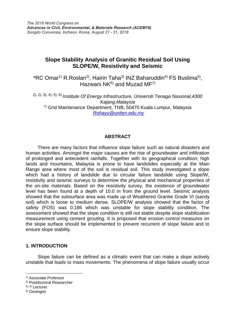
The 2018 World Congress on Advances in Civil, Environmental, & Materials Research (ACEM18) Songdo Convensia, Incheon, Korea, August 27 - 31, 2018 Slope Stability Analysis of Granitic Residual Soil Using SLOPE/W, Resistivity and Seismic *RC Omar 1) R.Roslan 2) , Hairin Taha 3) INZ Baharuddin 4) FS Buslima 5) , Hazwani NK 6) and Muzad MF 7) 1), 2), 3), 4), 5), 6) Institute Of Energy Infrastructure, Universiti Tenaga Nasional,4300 Kajang,Malaysia 7) Grid Maintenance Department, TNB, 50470 Kuala Lumpur, Malaysia [email protected] ABSTRACT There are many factors that influence slope failure such as natural disasters and human activities. Amongst the major causes are the rise of groundwater and infiltration of prolonged and antecedent rainfalls. Together with its geographical condition; high lands and mountains, Malaysia is prone to have landslides especially at the Main Range area where most of the soil is residual soil. This study investigated a slope which had a history of landslide due to circular failure landslide using Slope/W, resistivity and seismic surveys to determine the physical and mechanical properties of the on-site materials. Based on the resistivity survey, the existence of groundwater level has been found at a depth of 10.0 m from the ground level. Seismic analysis showed that the subsurface area was made up of Weathered Granite Grade VI (sandy soil) which is loose to medium dense. SLOPE/W analysis showed that the factor of safety (FOS) was 0.186 which was unstable for slope stability condition. The assessment showed that the slope condition is still not stable despite slope stabilization measurement using cement grouting. It is proposed that erosion control measures on the slope surface should be implemented to prevent recurrent of slope failure and to ensure slope stability. 1. INTRODUCTION Slope failure can be defined as a climatic event that can make a slope actively unstable that leads to mass movements. The phenomena of slope failure usually occur 1) Associate Professor 2) Postdoctoral Researcher 3), 4) Lecturer 5) Geologist
Transcript of Slope Stability Analysis of Granitic Residual Soil Using SLOPE/W, … · 2018-08-19 · slope...
The 2018 World Congress on Advances in Civil, Environmental, & Materials Research (ACEM18) Songdo Convensia, Incheon, Korea, August 27 - 31, 2018
Slope Stability Analysis of Granitic Residual Soil Using
SLOPE/W, Resistivity and Seismic
*RC Omar1) R.Roslan2), Hairin Taha3) INZ Baharuddin4) FS Buslima5), Hazwani NK6) and Muzad MF7)
1), 2), 3), 4), 5), 6) Institute Of Energy Infrastructure, Universiti Tenaga Nasional,4300
Kajang,Malaysia 7) Grid Maintenance Department, TNB, 50470 Kuala Lumpur, Malaysia
ABSTRACT
There are many factors that influence slope failure such as natural disasters and human activities. Amongst the major causes are the rise of groundwater and infiltration of prolonged and antecedent rainfalls. Together with its geographical condition; high lands and mountains, Malaysia is prone to have landslides especially at the Main Range area where most of the soil is residual soil. This study investigated a slope which had a history of landslide due to circular failure landslide using Slope/W, resistivity and seismic surveys to determine the physical and mechanical properties of the on-site materials. Based on the resistivity survey, the existence of groundwater level has been found at a depth of 10.0 m from the ground level. Seismic analysis showed that the subsurface area was made up of Weathered Granite Grade VI (sandy soil) which is loose to medium dense. SLOPE/W analysis showed that the factor of safety (FOS) was 0.186 which was unstable for slope stability condition. The assessment showed that the slope condition is still not stable despite slope stabilization measurement using cement grouting. It is proposed that erosion control measures on the slope surface should be implemented to prevent recurrent of slope failure and to ensure slope stability. 1. INTRODUCTION Slope failure can be defined as a climatic event that can make a slope actively unstable that leads to mass movements. The phenomena of slope failure usually occur
1) Associate Professor 2) Postdoctoral Researcher 3), 4) Lecturer 5) Geologist
The 2018 World Congress on Advances in Civil, Environmental, & Materials Research (ACEM18) Songdo Convensia, Incheon, Korea, August 27 - 31, 2018
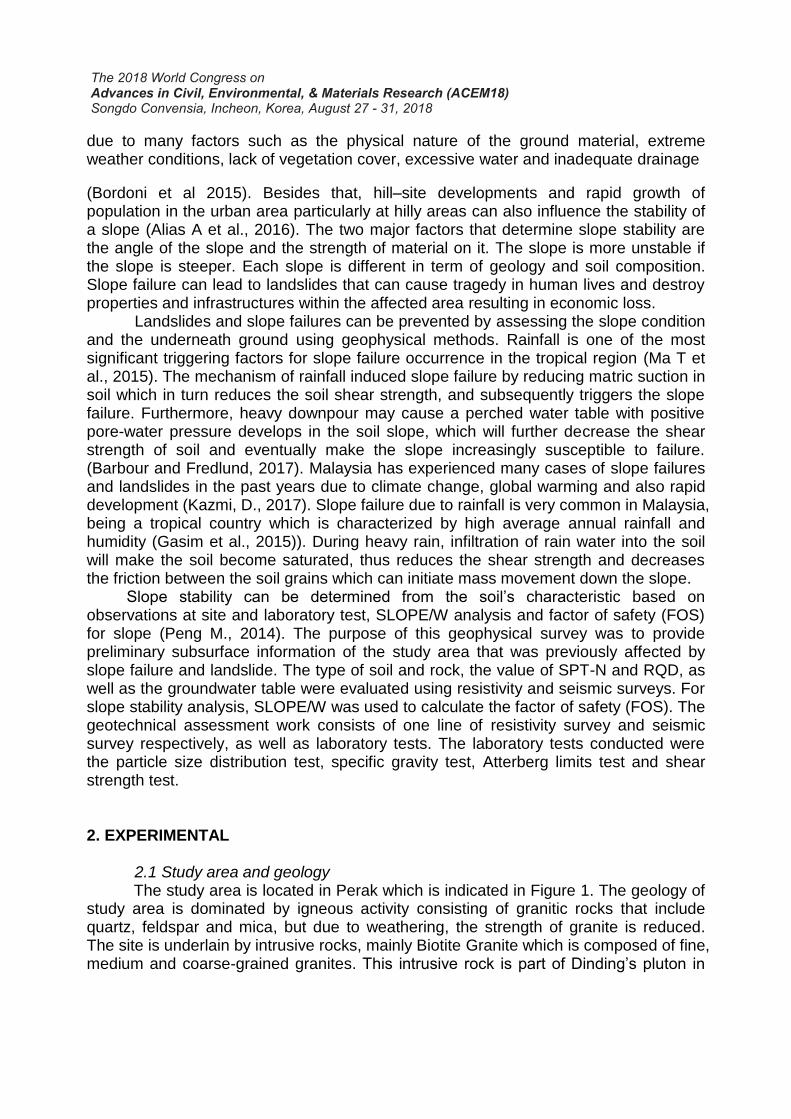
due to many factors such as the physical nature of the ground material, extreme weather conditions, lack of vegetation cover, excessive water and inadequate drainage
(Bordoni et al 2015). Besides that, hill–site developments and rapid growth of population in the urban area particularly at hilly areas can also influence the stability of a slope (Alias A et al., 2016). The two major factors that determine slope stability are the angle of the slope and the strength of material on it. The slope is more unstable if the slope is steeper. Each slope is different in term of geology and soil composition. Slope failure can lead to landslides that can cause tragedy in human lives and destroy properties and infrastructures within the affected area resulting in economic loss. Landslides and slope failures can be prevented by assessing the slope condition and the underneath ground using geophysical methods. Rainfall is one of the most significant triggering factors for slope failure occurrence in the tropical region (Ma T et al., 2015). The mechanism of rainfall induced slope failure by reducing matric suction in soil which in turn reduces the soil shear strength, and subsequently triggers the slope failure. Furthermore, heavy downpour may cause a perched water table with positive pore-water pressure develops in the soil slope, which will further decrease the shear strength of soil and eventually make the slope increasingly susceptible to failure. (Barbour and Fredlund, 2017). Malaysia has experienced many cases of slope failures and landslides in the past years due to climate change, global warming and also rapid development (Kazmi, D., 2017). Slope failure due to rainfall is very common in Malaysia, being a tropical country which is characterized by high average annual rainfall and humidity (Gasim et al., 2015)). During heavy rain, infiltration of rain water into the soil will make the soil become saturated, thus reduces the shear strength and decreases the friction between the soil grains which can initiate mass movement down the slope. Slope stability can be determined from the soil’s characteristic based on observations at site and laboratory test, SLOPE/W analysis and factor of safety (FOS) for slope (Peng M., 2014). The purpose of this geophysical survey was to provide preliminary subsurface information of the study area that was previously affected by slope failure and landslide. The type of soil and rock, the value of SPT-N and RQD, as well as the groundwater table were evaluated using resistivity and seismic surveys. For slope stability analysis, SLOPE/W was used to calculate the factor of safety (FOS). The geotechnical assessment work consists of one line of resistivity survey and seismic survey respectively, as well as laboratory tests. The laboratory tests conducted were the particle size distribution test, specific gravity test, Atterberg limits test and shear strength test. 2. EXPERIMENTAL 2.1 Study area and geology The study area is located in Perak which is indicated in Figure 1. The geology of study area is dominated by igneous activity consisting of granitic rocks that include quartz, feldspar and mica, but due to weathering, the strength of granite is reduced. The site is underlain by intrusive rocks, mainly Biotite Granite which is composed of fine, medium and coarse-grained granites. This intrusive rock is part of Dinding’s pluton in
The 2018 World Congress on Advances in Civil, Environmental, & Materials Research (ACEM18) Songdo Convensia, Incheon, Korea, August 27 - 31, 2018
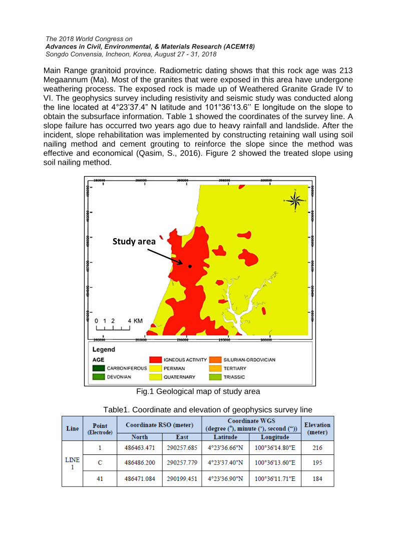
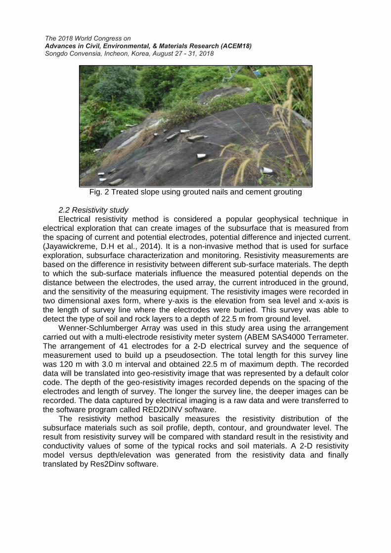
Main Range granitoid province. Radiometric dating shows that this rock age was 213 Megaannum (Ma). Most of the granites that were exposed in this area have undergone weathering process. The exposed rock is made up of Weathered Granite Grade IV to VI. The geophysics survey including resistivity and seismic study was conducted along the line located at 4°23’37.4” N latitude and 101°36’13.6’’ E longitude on the slope to obtain the subsurface information. Table 1 showed the coordinates of the survey line. A slope failure has occurred two years ago due to heavy rainfall and landslide. After the incident, slope rehabilitation was implemented by constructing retaining wall using soil nailing method and cement grouting to reinforce the slope since the method was effective and economical (Qasim, S., 2016). Figure 2 showed the treated slope using soil nailing method.
Fig.1 Geological map of study area
Table1. Coordinate and elevation of geophysics survey line
The 2018 World Congress on Advances in Civil, Environmental, & Materials Research (ACEM18) Songdo Convensia, Incheon, Korea, August 27 - 31, 2018
Fig. 2 Treated slope using grouted nails and cement grouting
2.2 Resistivity study Electrical resistivity method is considered a popular geophysical technique in electrical exploration that can create images of the subsurface that is measured from the spacing of current and potential electrodes, potential difference and injected current. (Jayawickreme, D.H et al., 2014). It is a non-invasive method that is used for surface exploration, subsurface characterization and monitoring. Resistivity measurements are based on the difference in resistivity between different sub-surface materials. The depth to which the sub-surface materials influence the measured potential depends on the distance between the electrodes, the used array, the current introduced in the ground, and the sensitivity of the measuring equipment. The resistivity images were recorded in two dimensional axes form, where y-axis is the elevation from sea level and x-axis is the length of survey line where the electrodes were buried. This survey was able to detect the type of soil and rock layers to a depth of 22.5 m from ground level. Wenner-Schlumberger Array was used in this study area using the arrangement carried out with a multi-electrode resistivity meter system (ABEM SAS4000 Terrameter. The arrangement of 41 electrodes for a 2-D electrical survey and the sequence of measurement used to build up a pseudosection. The total length for this survey line was 120 m with 3.0 m interval and obtained 22.5 m of maximum depth. The recorded data will be translated into geo-resistivity image that was represented by a default color code. The depth of the geo-resistivity images recorded depends on the spacing of the electrodes and length of survey. The longer the survey line, the deeper images can be recorded. The data captured by electrical imaging is a raw data and were transferred to the software program called RED2DINV software. The resistivity method basically measures the resistivity distribution of the subsurface materials such as soil profile, depth, contour, and groundwater level. The result from resistivity survey will be compared with standard result in the resistivity and conductivity values of some of the typical rocks and soil materials. A 2-D resistivity model versus depth/elevation was generated from the resistivity data and finally translated by Res2Dinv software.
The 2018 World Congress on Advances in Civil, Environmental, & Materials Research (ACEM18) Songdo Convensia, Incheon, Korea, August 27 - 31, 2018
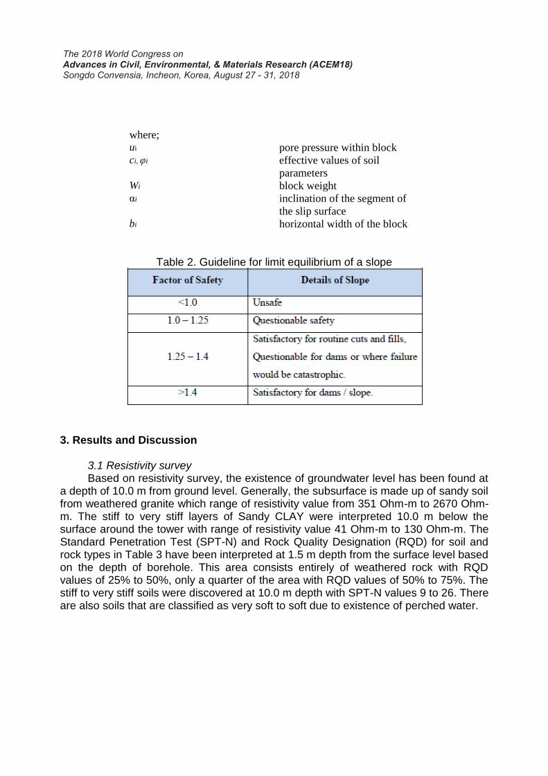
2.3 Seismic survey Seismic methods are based on elastic wave (also known a seismic, shockwave, or acoustic wave) that travel through the sub-surface (Hibbs, A. and Wilt, M., 2016) . The wave is refracted on boundaries characterized by different densities and physical properties. Seismic refraction is based on the first arrival of a signal that travels through a layer with a higher velocity. The seismic image was recorded in the form of two dimensional axes, where y-axis is the travel time of seismic wave (ms-1) and depth below ground level (m) and x-axis is the length of survey line where the geophones were buried. A 24 channels ABEM Terraloc Mark 6, geophones for S-wave and P-wave and hammer were used for this study. Seismic survey was conducted using a 120 m in length with 5.0 m geophones spacing. A 4.5 kg hammer was used to produce pressure waves with seven points of impact from hammer towards steel plate to obtain proper readings. Energy will radiate out from the shot point, either by travelling directly through the upper layer (direct arrivals), or travelling down to and then laterally along higher velocity layers (refracted arrivals) before returning to the surface. This energy is detected on the surface using a linear array of geophones. Observation of the refracted signals provides information on the depth profile of the refractor. The raw data was captured by wave imaging from ABEM Terraloc Mark 6 and processed using software program called Interpex Seismic Refraction Interpretation Software (IXRefraX). 2.4 Slope W analysis SLOPE/W computes Factor of Safety (FOS) for various shear surfaces and the software can generate more than one angle of slopes and different type of soils. Factor of safety (FOS) is defined as the ratio of the shear strength to shear stress along a critical failure surface (Reale, C., 2015). Analyses must be based upon a model that accurately represent site subsurface conditions, and ground behavior when using SLOPE/W software. Analysis of stability is mostly conducted using Bishop Method as shown in Eq. (1). The factor of safety (FOS) is therefore chosen as a ratio of the available shear strength to that required to keep the slope stable. Table 2 shows the guideline for limit equilibrium of slope, which represents the condition of slope based on its FOS value. These values of FOS will be compared with FOS value obtained from SLOPE/W to get the condition of slope. If the value of FOS is 1.0, the slope is in a state of impending failure. The required factor of safety ranges between 1.25-1.5. In general, the value of FOS with respect to strength that is acceptable for the design of a stable slope is 1.5.
(1)
The 2018 World Congress on Advances in Civil, Environmental, & Materials Research (ACEM18) Songdo Convensia, Incheon, Korea, August 27 - 31, 2018
where; ui pore pressure within block ci, φi effective values of soil
parameters Wi block weight αi inclination of the segment of
the slip surface bi horizontal width of the block
Table 2. Guideline for limit equilibrium of a slope
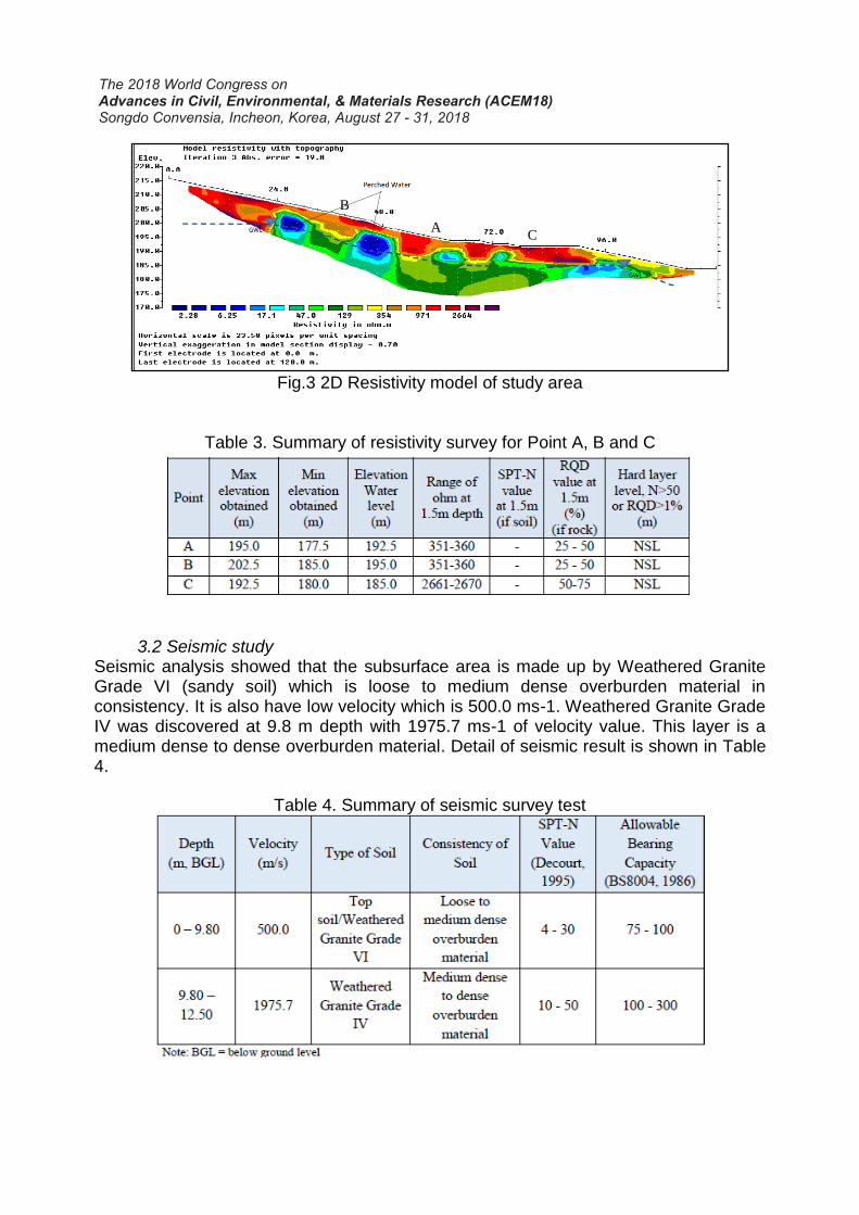
3. Results and Discussion 3.1 Resistivity survey Based on resistivity survey, the existence of groundwater level has been found at a depth of 10.0 m from ground level. Generally, the subsurface is made up of sandy soil from weathered granite which range of resistivity value from 351 Ohm-m to 2670 Ohm-m. The stiff to very stiff layers of Sandy CLAY were interpreted 10.0 m below the surface around the tower with range of resistivity value 41 Ohm-m to 130 Ohm-m. The Standard Penetration Test (SPT-N) and Rock Quality Designation (RQD) for soil and rock types in Table 3 have been interpreted at 1.5 m depth from the surface level based on the depth of borehole. This area consists entirely of weathered rock with RQD values of 25% to 50%, only a quarter of the area with RQD values of 50% to 75%. The stiff to very stiff soils were discovered at 10.0 m depth with SPT-N values 9 to 26. There are also soils that are classified as very soft to soft due to existence of perched water.
The 2018 World Congress on Advances in Civil, Environmental, & Materials Research (ACEM18) Songdo Convensia, Incheon, Korea, August 27 - 31, 2018
Fig.3 2D Resistivity model of study area
Table 3. Summary of resistivity survey for Point A, B and C
3.2 Seismic study Seismic analysis showed that the subsurface area is made up by Weathered Granite Grade VI (sandy soil) which is loose to medium dense overburden material in consistency. It is also have low velocity which is 500.0 ms-1. Weathered Granite Grade IV was discovered at 9.8 m depth with 1975.7 ms-1 of velocity value. This layer is a medium dense to dense overburden material. Detail of seismic result is shown in Table 4.
Table 4. Summary of seismic survey test
A
B
C
The 2018 World Congress on Advances in Civil, Environmental, & Materials Research (ACEM18) Songdo Convensia, Incheon, Korea, August 27 - 31, 2018
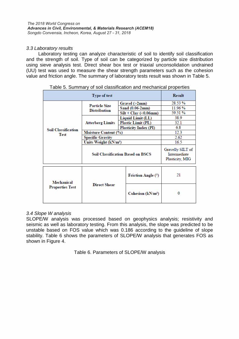
3.3 Laboratory results Laboratory testing can analyze characteristic of soil to identify soil classification and the strength of soil. Type of soil can be categorized by particle size distribution using sieve analysis test. Direct shear box test or triaxial unconsolidation undrained (UU) test was used to measure the shear strength parameters such as the cohesion value and friction angle. The summary of laboratory tests result was shown in Table 5.
Table 5. Summary of soil classification and mechanical properties
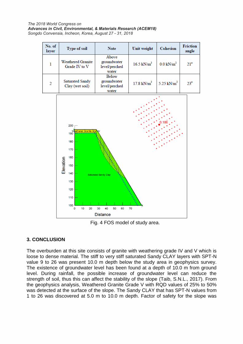
3.4 Slope W analysis SLOPE/W analysis was processed based on geophysics analysis; resistivity and seismic as well as laboratory testing. From this analysis, the slope was predicted to be unstable based on FOS value which was 0.186 according to the guideline of slope stability. Table 6 shows the parameters of SLOPE/W analysis that generates FOS as shown in Figure 4.
Table 6. Parameters of SLOPE/W analysis
The 2018 World Congress on Advances in Civil, Environmental, & Materials Research (ACEM18) Songdo Convensia, Incheon, Korea, August 27 - 31, 2018
Fig. 4 FOS model of study area. 3. CONCLUSION The overburden at this site consists of granite with weathering grade IV and V which is loose to dense material. The stiff to very stiff saturated Sandy CLAY layers with SPT-N value 9 to 26 was present 10.0 m depth below the study area in geophysics survey. The existence of groundwater level has been found at a depth of 10.0 m from ground level. During rainfall, the possible increase of groundwater level can reduce the strength of soil, thus this can affect the stability of the slope (Taib, S.N.L., 2017). From the geophysics analysis, Weathered Granite Grade V with RQD values of 25% to 50% was detected at the surface of the slope. The Sandy CLAY that has SPT-N values from 1 to 26 was discovered at 5.0 m to 10.0 m depth. Factor of safety for the slope was
The 2018 World Congress on Advances in Civil, Environmental, & Materials Research (ACEM18) Songdo Convensia, Incheon, Korea, August 27 - 31, 2018
0.186 which is less than 1.0 indicating the instability of the slope condition. The actual slope circle failure has already taken place at the study site and the soil nailing was installed to prevent further slope failure. Constant monitoring should be carried out on existing slope (Stähli, M., 2015). The study area was also experiencing soil erosion on the surface due to the existence of small gully that has developed previously. Therefore, erosion control measures should be carried out to prevent or reduce movement of eroded soil sediments off-site or land. The controls often involve the creation of a physical barrier, such as vegetation cover or rock, to absorb some of the energy of water that is causing the erosion. The stability of a soil-nailed system throughout its design life should also be assessed. Its performance should not exceed a state at which failure mechanisms can form in the ground or within the soil-nailed system, or when movement of the soil-nailed system can lead to severe damage to its structural elements or nearby structures, facilities or services. For this area, the design of a soil-nailed system should be ensured that there is an adequate safety margin against all the perceived potential modes of failure. The environmental conditions should be investigated at the design stage to assess their significance in relation to the durability of soil nails. Appropriate measures should be applied to the soil nails such that an adequate safety margin of the soil-nailed system can be maintained throughout its design life. The durability of a steel soil-nailed system is governed primarily by the resistance to corrosion under different soil aggressivity. ACKNOWLEDGEMENT The author would like to convey her gratitude to Forensic Engineering Group, Institute of Energy Infrastructure for the opportunity to be one of the team members in this research. This research was funded by UNITEN R&D Sdn. Bhd. through Research Grant No. U-TS-CR-12-06. REFERENCES Bordoni, M., Meisina, C., Valentino, R., Lu, N., Bittelli, M. and Chersich, S., 2015. Hydrological factors affecting rainfall-induced shallow landslides: from the field monitoring to a simplified slope stability analysis. Engineering Geology, 193, pp.19-37. Alias, A. and Ali, A.S., 2016. Challenges and control mechanism for development on highland and steep slope: The case of Klang Valley. Malaysian Construction Research Journal, 18(1), pp.41-58. Ma, T., Li, C., Lu, Z. and Bao, Q., 2015. Rainfall intensity–duration thresholds for the initiation of landslides in Zhejiang Province, China. Geomorphology, 245, pp.193-206. Barbour, S.L. and Fredlund, D.G., 2017. Integrated seepage modelling and slope stability analyses: A generalized approach for saturated/unsaturated soils. In Geomechanics and Water Engineering in Environmental Management (pp. 3-35). Routledge.
The 2018 World Congress on Advances in Civil, Environmental, & Materials Research (ACEM18) Songdo Convensia, Incheon, Korea, August 27 - 31, 2018
Muhammad Barzani Gasim, Mohd Ekhwan Toriman and Hafizan Juahir, 2015. Phenomenon of Slope Failure Occurrences along Gerik-Jeli Highway, Malaysia. Journal of Applied Sciences, 15: 545-551. Peng, M., Li, X.Y., Li, D.Q., Jiang, S.H. and Zhang, L.M., 2014. Slope safety evaluation by integrating multi-source monitoring information. Structural Safety, 49, pp.65-74. Jayawickreme, D.H., Jobbágy, E.G. and Jackson, R.B., 2014. Geophysical subsurface imaging for ecological applications. New Phytologist, 201(4), pp.1170-1175. Hibbs, A. and Wilt, M., 2016. Evaluation of deep subsurface resistivity imaging for hydrofracture monitoring. GroundMetrics, Inc., San Diego, CA (United States). Reale, C., Xue, J., Pan, Z. and Gavin, K., 2015. Deterministic and probabilistic multi-modal analysis of slope stability. Computers and Geotechnics, 66, pp.172-179. Kazmi, D., Qasim, S., Harahap, I.S.H., Baharom, S., Imran, M. and Moin, S., 2017. A study on the contributing factors of major landslides in Malaysia. Civil Engineering Journal, 2(12), pp.669-678. Stähli, M., Sättele, M., Huggel, C., McArdell, B.W., Lehmann, P., Van Herwijnen, A., Berne, A., Schleiss, M., Ferrari, A., Kos, A. and Or, D., 2015. Monitoring and prediction in early warning systems for rapid mass movements. Natural Hazards and Earth System Sciences, 15(4), pp.905-917. Taib, S.N.L., Selaman, O.S., Chen, C.L., Lim, R. and Awang Ismail, D.S., 2017. Landslide Susceptibility in Relation to Correlation of Groundwater Development and Ground Condition. Advances in Civil Engineering, 2017. Qasim, S., Harahap, I.S.H., Baharom, S., Imran, M. and Kazmi, D., 2016, December. Investigating the potential of soil-nail retaining structures as a slope strengthening remedy by capitalizing on reliability analysis technique. In Engineering Challenges for Sustainable Future: Proceedings of the 3rd International Conference on Civil, Offshore and Environmental Engineering (ICCOEE 2016, Malaysia, 15-17 Aug 2016) (p. 27). CRC Press.