Slope Stability Analysis
15
NYSDOT Geotechnical Page 10-1 January 21, 2014 Design Manual GEOTECHNICAL DESIGN MANUAL CHAPTER 10 SLOPE STABILITY ANALYSIS
-
Upload
ahsan-rabbani -
Category
Documents
-
view
26 -
download
4
description
10.2.2 Slope GeometryRepresentative slope geometry is required for slope stability analysis, and should include accurate locations of streams, roads, structures, and utilities. Surfaces needed to reflect slope geometry can be derived from photogrammetric mapping, field surveys, or published topographic maps. For side hill conditions, cross sections should be carried above the existing road or to a controlling feature such as rock outcrop and down to the bottom of the natural slope. If a watercourse occurs at the bottom of the slope then the stream bed should be surveyed or estimated. Cracks caused by earth movement should be mapped to provide a realistic failure model.10.2.3 Soil Shear StrengthThe shear strength of the soil along the failure surface is a function of the effective stress at failure. The effective stress can only be calculated indirectly if the pore water pressures at the state of failure are known, both in the laboratory and in the field. Consolidated undrained triaxial tests with pore pressure (CU/p) measurements are commonly performed by NYSDOT to determine the drained friction angle of the critical soil. This test also provides a range of undrained shear strengths at various confining stresses levels. See NYSDOT GDM Chapter 8 for guidance on the development of shear strength parameters.
Transcript of Slope Stability Analysis
NYSDOT Geotechnical Page 10-1 January 21, 2014
Design Manual
GEOTECHNICAL DESIGN MANUAL
CHAPTER 10
SLOPE STABILITY ANALYSIS

NYSDOT Geotechnical Page 10-2 January 21, 2014
Design Manual
(Intentionally left blank)
Table of Contents
NYSDOT Geotechnical Page 10-3 January 21, 2014
Design Manual
10.1 OVERVIEW .................................................................................................................. 10-4
10.2 REQUIRED INPUT DATA FOR SLOPE STABILITY ANALYSIS ........................... 10-5
10.2.1 Soil Profile ......................................................................................................... 10-5
10.2.2 Slope Geometry .................................................................................................. 10-6
10.2.3 Soil Shear Strength ............................................................................................ 10-6
10.2.4 Pore Water Pressure ........................................................................................... 10-8
10.3 METHODS OF STABILITY ANALYSIS .................................................................... 10-9
10.3.1 Limit Equilibrium Equations ............................................................................. 10-9
10.3.2 Preliminary Methods ........................................................................................ 10-10
10.3.3 Method of Slices .............................................................................................. 10-11
10.3.4 Methods Derived from Method of Slices ......................................................... 10-11
10.3.5 Comparison of Methods ................................................................................... 10-13
10.3.6 Back Analysis .................................................................................................. 10-14
10.3.7 Evaluation of Remedial Methods ..................................................................... 10-14
10.3.8 Computer Programs ......................................................................................... 10-14
10.3.9 Required Factor of Safety ................................................................................ 10-14
10.4 REFERENCES ............................................................................................................ 10-15
CHAPTER 10
Slope Stability Analysis
NYSDOT Geotechnical Page 10-4 January 21, 2014
Design Manual
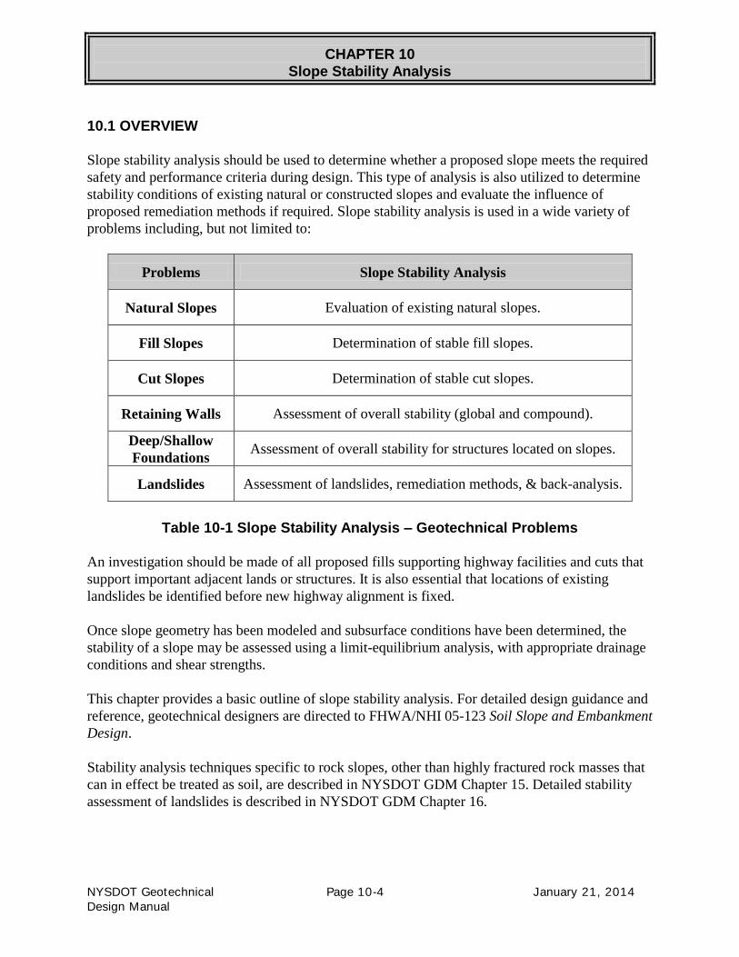
10.1 OVERVIEW
Slope stability analysis should be used to determine whether a proposed slope meets the required
safety and performance criteria during design. This type of analysis is also utilized to determine
stability conditions of existing natural or constructed slopes and evaluate the influence of
proposed remediation methods if required. Slope stability analysis is used in a wide variety of
problems including, but not limited to:
Problems Slope Stability Analysis
Natural Slopes Evaluation of existing natural slopes.
Fill Slopes Determination of stable fill slopes.
Cut Slopes Determination of stable cut slopes.
Retaining Walls Assessment of overall stability (global and compound).
Deep/Shallow
Foundations Assessment of overall stability for structures located on slopes.
Landslides Assessment of landslides, remediation methods, & back-analysis.
Table 10-1 Slope Stability Analysis – Geotechnical Problems
An investigation should be made of all proposed fills supporting highway facilities and cuts that
support important adjacent lands or structures. It is also essential that locations of existing
landslides be identified before new highway alignment is fixed.
Once slope geometry has been modeled and subsurface conditions have been determined, the
stability of a slope may be assessed using a limit-equilibrium analysis, with appropriate drainage
conditions and shear strengths.
This chapter provides a basic outline of slope stability analysis. For detailed design guidance and
reference, geotechnical designers are directed to FHWA/NHI 05-123 Soil Slope and Embankment
Design.
Stability analysis techniques specific to rock slopes, other than highly fractured rock masses that
can in effect be treated as soil, are described in NYSDOT GDM Chapter 15. Detailed stability
assessment of landslides is described in NYSDOT GDM Chapter 16.

CHAPTER 10
Slope Stability Analysis
NYSDOT Geotechnical Page 10-5 January 21, 2014
Design Manual
10.2 REQUIRED INPUT DATA FOR SLOPE STABILITY ANALYSIS
It is expected that geotechnical designers performing slope stability analysis on NYSDOT
projects include the following basic data in the stability model:
Parameter Basic Input Data
Soil Profile Detailed Assessment of Soil Stratigraphy
Slope Geometry Derived from Topos, Photogrammetry and Survey
Soil Shear Strength Total and Effective Stress Analysis
Pore Water Pressure Determination of Water Regime
Table 10-2 Basic Input Data
The input data needed for slope stability analysis is also described in:
• NYSDOT GDM Chapter 2 Project Geotechnical Planning
• NYSDOT GDM Chapter 6 Engineering Properties of Soil and Rock
• NYSDOT GDM Chapter 13 Soil Cut Design
• NYSDOT GDM Chapter 15 Rock Cut Design
• NYSDOT GDM Chapter 16 Landslide Analysis and Mitigation
10.2.1 Soil Profile
Detailed assessment of soil stratigraphy is critical so that a representative soil profile can be
modeled. It is important to define any thin, weak layers present, (i.e. the presence of silt-clay
varves, etc.) as these fine details of the stratigraphy could control the stability of the slope in
question. Knowledge of the geologic nature of the units present at a site, including past
performance, is necessary for appropriate determination of ground conditions and the
development of a realistic geotechnical model.
The location and characteristics of the critical soil strata are usually obtained by taking
continuous split spoon or thin-walled tube samples. Borings should be progressed in sufficient
quantities to adequately define subsurface materials. In a potential slide area, borings should be
taken at the top and bottom of existing or proposed slopes if possible. The number of borings
required longitudinally depends on the continuity of the soil conditions and the extent of the
possible problems as discussed in NYSDOT GDM Chapter 4. Seismic investigation can be a
useful supplement if the rock surface is a major influencing factor.

CHAPTER 10
Slope Stability Analysis
NYSDOT Geotechnical Page 10-6 January 21, 2014
Design Manual
10.2.2 Slope Geometry
Representative slope geometry is required for slope stability analysis, and should include
accurate locations of streams, roads, structures, and utilities. Surfaces needed to reflect slope
geometry can be derived from photogrammetric mapping, field surveys, or published topographic
maps. For side hill conditions, cross sections should be carried above the existing road or to a
controlling feature such as rock outcrop and down to the bottom of the natural slope. If a
watercourse occurs at the bottom of the slope then the stream bed should be surveyed or
estimated. Cracks caused by earth movement should be mapped to provide a realistic failure
model.
10.2.3 Soil Shear Strength
The shear strength of the soil along the failure surface is a function of the effective stress at
failure. The effective stress can only be calculated indirectly if the pore water pressures at the
state of failure are known, both in the laboratory and in the field. Consolidated undrained triaxial
tests with pore pressure (CU/p) measurements are commonly performed by NYSDOT to
determine the drained friction angle of the critical soil. This test also provides a range of
undrained shear strengths at various confining stresses levels. See NYSDOT GDM Chapter 8 for
guidance on the development of shear strength parameters.
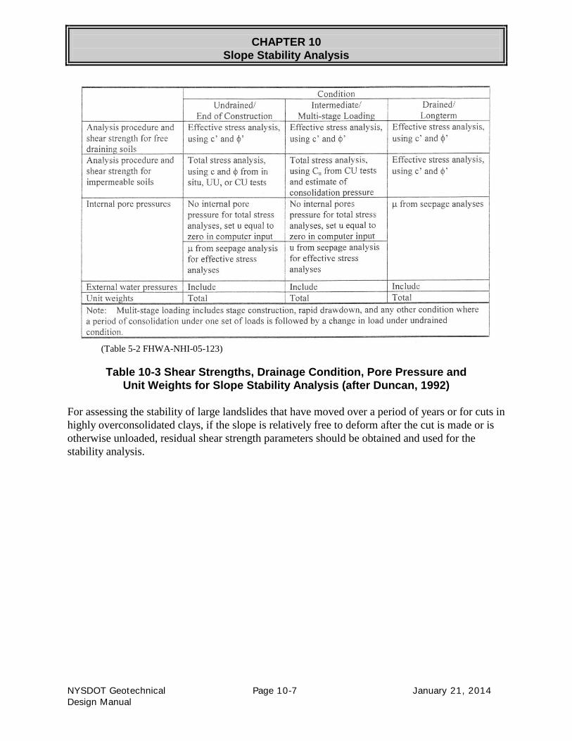
The geotechnical designer should determine if subject slope consisting of cohesive, impermeable
soils will experience loading and at what rate of load will be applied – short-term (rapid loading
condition, ie. construction loading), long-term (very slow loading condition), or a multi-stage
loading (placement of a portion of load, followed by waiting period). The rate of load application
will determine the selection of soil shear strength parameters used as input in the analysis as
follows:
CHAPTER 10
Slope Stability Analysis
NYSDOT Geotechnical Page 10-7 January 21, 2014
Design Manual
(Table 5-2 FHWA-NHI-05-123)
Table 10-3 Shear Strengths, Drainage Condition, Pore Pressure and
Unit Weights for Slope Stability Analysis (after Duncan, 1992)
For assessing the stability of large landslides that have moved over a period of years or for cuts in
highly overconsolidated clays, if the slope is relatively free to deform after the cut is made or is
otherwise unloaded, residual shear strength parameters should be obtained and used for the
stability analysis.

CHAPTER 10
Slope Stability Analysis
NYSDOT Geotechnical Page 10-8 January 21, 2014
Design Manual
10.2.4 Pore Water Pressure
A change in effective stress caused by pore water pressure is a major contributor of slope failures
because the pressures tend to alter the shear strength of the soil along the shear zone. An
understanding of pore water pressure and groundwater regime at the study site is critical for
establishing an accurate model for slope stability analysis.
Figure 10-1 Types of Aquifers (US Department of the Interior, 1981)
Detailed piezometric data at multiple locations and depths within and below the slope might be
required, depending on the geologic complexity of the stratigraphy and groundwater conditions.
The use of piezometers (vibrating-wire or open-well) should be considered if the existing or
future groundwater conditions cannot be readily determined by field observation and these
conditions would have a detrimental effect on the stability of the slope or cut based on the nature
of the subsurface materials or geometry of the site. Separate piezometers sealed into multiple soil
or rock deposits may be necessary to obtain a better estimate of the groundwater conditions.
Sudden drawdown is a rapid lowering in the level of water standing against a slope. This
condition can occur on the slopes adjacent to a reservoir, river, or canal either following a long
period of rainfall accumulation, planned lowering of water through control structures, or failure
of water impoundment structure. Sudden drawdown often occurs in clayey slopes in which the
excess pore water pressures do not dissipate as the water recedes, thereby keeping the overall
shear strength low.
CHAPTER 10
Slope Stability Analysis
NYSDOT Geotechnical Page 10-9 January 21, 2014
Design Manual
10.3 METHODS OF STABILITY ANALYSIS
Methods of stability analysis are detailed in Publication No. FHWA/NHI 05-123 Soil Slope and
Embankment Design.
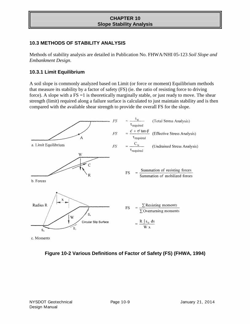
10.3.1 Limit Equilibrium
A soil slope is commonly analyzed based on Limit (or force or moment) Equilibrium methods
that measure its stability by a factor of safety (FS) (ie. the ratio of resisting force to driving
force). A slope with a FS =1 is theoretically marginally stable, or just ready to move. The shear
strength (limit) required along a failure surface is calculated to just maintain stability and is then
compared with the available shear strength to provide the overall FS for the slope.
Figure 10-2 Various Definitions of Factor of Safety (FS) (FHWA, 1994)

CHAPTER 10
Slope Stability Analysis
NYSDOT Geotechnical Page 10-10 January 21, 2014
Design Manual
10.3.2 Preliminary Methods
The following figure shows limit equilibrium methods that can be readily solved by hand or
spreadsheet and do not depend on the distribution of the effective normal stress along the failure
surface. Published design charts and methods shown in following figure should be only used for
preliminary evaluation of slopes and are described in detail in FHWA/NHI 05-123.
Infinite Slope
Planar
Circular, Log Spiral
Block
Figure 10-3 Limit Equilibrium Methods

CHAPTER 10
Slope Stability Analysis
NYSDOT Geotechnical Page 10-11 January 21, 2014
Design Manual
10.3.3 Method of Slices
If mobilized strength for a soil is to be calculated, the distribution of the effective normal stresses
along the failure must be known. This condition is usually analyzed by sectioning the potential
failure mass into small vertical slices and treating each as a unique sliding block. This analysis is
known as the Method of Slices.
Figure 10-4 Method of Slices
10.3.4 Methods Derived from Method of Slices
A number of limit equilibrium methods are based on the Method of Slices. While originally
calculated by hand, these more rigorous methods were converted to computerized versions which
are commercially available to geotechnical designers doing work for NYSDOT.
The methods are generally divided into three categories, based on the number of equilibrium
equations to be satisfied:
1. Overall moment equilibrium methods,
2. Force equilibrium methods, and
3. Moment and force equilibrium methods.
Slope stability problems are usually statically indeterminate. Assumptions are generally involved
to render the problem determinate, with each method of analysis using a different assumption. As
a result, the computed factor of safety varies between the different methods. The following table
lists commonly available methods of analysis and the conditions of static equilibrium that are
satisfied in determining the factor of safety.

CHAPTER 10
Slope Stability Analysis
NYSDOT Geotechnical Page 10-12 January 21, 2014
Design Manual
Table 10-4 Static Equilibrium Conditions Satisfied by Limit Equilibrium Methods
CHAPTER 10
Slope Stability Analysis
NYSDOT Geotechnical Page 10-13 January 21, 2014
Design Manual
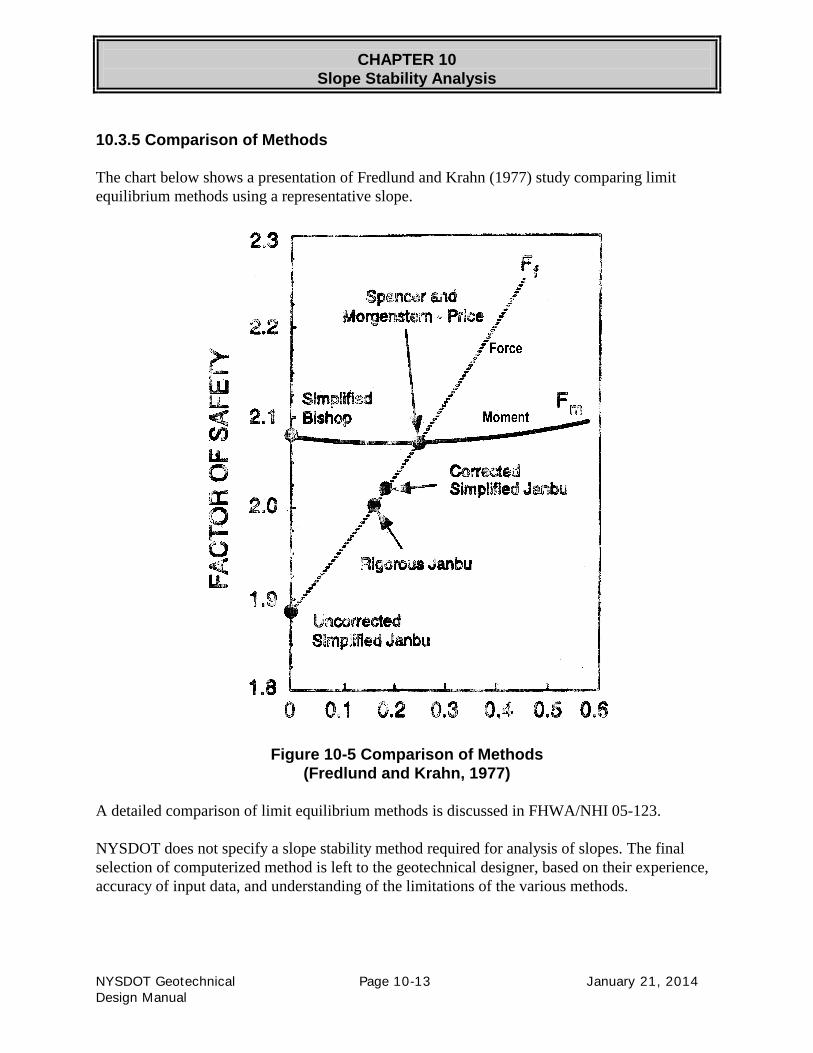
10.3.5 Comparison of Methods
The chart below shows a presentation of Fredlund and Krahn (1977) study comparing limit
equilibrium methods using a representative slope.
Figure 10-5 Comparison of Methods
(Fredlund and Krahn, 1977)
A detailed comparison of limit equilibrium methods is discussed in FHWA/NHI 05-123.
NYSDOT does not specify a slope stability method required for analysis of slopes. The final
selection of computerized method is left to the geotechnical designer, based on their experience,
accuracy of input data, and understanding of the limitations of the various methods.

CHAPTER 10
Slope Stability Analysis
NYSDOT Geotechnical Page 10-14 January 21, 2014
Design Manual
10.3.6 Back Analysis
After a slope failure, an analysis is usually performed in an effort to identify probable causes. By
using a known or assumed failure surface, some form of back analysis can be performed in order
to estimate the material shear strength, pore pressure or other conditions at the time of failure.
10.3.7 Evaluation of Remedial Methods
Once the failure surface is identified by back analysis, the soil strengths and pore pressures can
be adjusted until the calculated FS is equal to 1.0. The chosen soil strengths and pore pressures
can then be used to evaluate repair methods and determine relative improvement to the FS. Based
on incremental improvement of FS and other constraints (economical, environmental, real estate,
impacts to public, etc.) the geotechnical designer can then recommend appropriate remedial
actions.
Mitigation measures for slope failures are described in NYSDOT GDM Chapter 16 and Chapter
22.
10.3.8 Computer Programs
The Geotechnical Engineering Bureau currently uses SLOPE/W (2012) to perform slope stability
analysis. XSTABL is also used to calculate the factors of safety according to the Simplified
Bishop and Simplified Janbu methods of analysis.
10.3.9 Factor of Safety
The following table provides minimum NYSDOT required Factors of Safety if a geotechnical
designer has enough information to adequately define soil profile, slope geometry, soil shear
strength and pore water pressure in a slope stability model:
Geotechnical Element FS LRFD
Embankment Side Slopes 1.25 -
Embankment End slopes 1.30 -
Cut Slopes 1.50 -
Landslide Remediation 1.25 -
Bridge or Wall Structure on Slope* 1.50 .65
Minor Wall with Minimal Impact on Slope* 1.30 .75
*Load Factor of 1.
Table 10-5 Minimum Required Factors of Safety – Slope Stability Analysis
CHAPTER 10
Slope Stability Analysis
NYSDOT Geotechnical Page 10-15 January 21, 2014
Design Manual
10.4 REFERENCES
Abramson, L., Boyce, G., Lee, T., and Sharma, S., Advanced Technology for Soil Slope Stability,
Volume 1: Slope Stability Manual, Publication No. FHWA-SA-94-005, 1994.
Collin, James G, Leshchinsky, D., and Hung, C., Soil Slope and Embankment Design,
Publication No. FHWA/NHI-05-123.
Geotechnical Engineering Bureau, Design Procedure for Launched Soil Nail Shallow Slough
Treatment, Geotechnical Design Procedure GDP-14, New York State Department of
Transportation, Office of Technical Services,
https://www.dot.ny.gov/divisions/engineering/technical-services/technical-services-
repository/GDP-14b.pdf
McGuffey, V.G., Earth Cut Slope Design in New York State, Highway Research Record, Number
457, 1973.


![[0] FEM in Slope Stability Analysis](https://static.fdocuments.in/doc/165x107/577ce1941a28ab9e78b5c6a0/0-fem-in-slope-stability-analysis.jpg)