Slope-deflection method - College of Engineering, Purdue University
222
H ILL I N 0 I S UNIVERSITY OF ILLINOIS AT URBANA-CHAMPAIGN PRODUCTION NOTE University of Illinois at Urbana-Champaign Library Large-scale Digitization Project, 2007.
Transcript of Slope-deflection method - College of Engineering, Purdue University

HILL I N 0 I SUNIVERSITY OF ILLINOIS AT URBANA-CHAMPAIGN
PRODUCTION NOTE
University of Illinois atUrbana-Champaign Library
Large-scale Digitization Project, 2007.


208. E *^ VER'qr k STATIf^ftteft
UNIVERSITY OF' IL..LINOIS ULLED TIN
Vol. XVI NOvEmER 4, 1918 No. 1019tered as seoi d-clia matte Detmber 11, 1912, at the poet ofce at -rbuau. flHinis, under thwAct of Augut
24, 1912. Acceptanoe for utaiug at the speoal rate of postag provided tr i BootSeion 1102.Aet of ,ctobr3. 917, autho isBd July 31, 1918).1
ANALYSIS OF' STATICALLY INDETER-MINATE STRUCTURES BY THESLOPE DEFLECTION MIETHOD
W. MF. WILSONF. E. RICHART AND AMILLO WEISS
BULLETIN No.W1r08
ENGINEERING EXPERIMENT STATIONPuBnEn By THE iUNrMDuB OF ILu h 0orn, URBANA
PRICE: GOnA DLouAnEUROrEAN AGIC
-CpHuAPA & IAiLt, Ld, LoNDob-
i^^.^^^-^-^^^C,.4
J.
I®?-'^;-'^^^-^N N 4 -ge^
"5 4^^^^^i
T HE Engineering Experiment Station was established by act ofj the Board of Trustees, December 8,. 1903. It is the purpose
of the Station to carry on investigations along various lines of
engineering and to study problems of importance to professional engi-
neers and to the manufacturing, railway, mining, constructional, and
industrial interests of the State.
The control of the Engineering Experiment Station is vested in
the heads of the several departments of the College of Engineering.
These constitute the Station Staff and, with the Director, determine
the character of the investigations to be undertaken. The work is
carried on under the supervision of the Staff, sometimes by research
fellows as graduate work, sometimes by members of the instructional
staff of the College of Engineering, but more frequently by investigators
belonging to the Station corps.
The results of these investigations are published in the form of
bulletins, which record mostly the experiments of the StatiWh's own
staff of investigators. There will also be issued from time to time, in
the form of circulars, compilations giving the results of the experi-
ments of engineers, industrial works, technical institutions,, and gov-
ernmental testing departments.
The volume and number at the top of the front cover page are
merely arbitrary nunbers and refer to the generalpublications of the
University of Illinois: eWither above the titek or below the seal is given
the number of the Engineering Experiment Station bulletin or circular
which should be used in referring to these publications.
.For copies of bulletins, circulars, or other information address the
ENGINEERING ExPERIMENT STATION,
URBANA, I .NI .
'r,;^'
UNIVERSITY OF ILLINOIS
ENGINEERING EXPERIMENT STATION
BULLETIN NO. 108 NOVEMBER, 1918
ANALYSIS OF STATICALLY INDETER-
MINATE STRUCTURES BY THE
SLOPE DEFLECTION METHOD
BY
W. M. WILSONASSISTANT PROFESSOR OF CIVIL ENGINEERING
F. E. RICHARTINSTRUCTOR IN THEORETICAL AND APPLIED MECHANICS
AND
CAMILLO WEISSINSTRUCTOR IN STRUCTURAL ENGINEERING
ENGINEERING EXPERIMENT STATIONPUBLISHED BY THE UNIVERSITY or ILLINOIS, URBANA

CONTENTSPAGE
I. PRELIMINARY . . . . . . . . . . . . . . 91. Object and Scope of Investigation . . . . . . 92. Acknowledgments . . . . . . . . . . 9
PART I
DERIVATION OF FUNDAMENTAL EQUATIONS
II. PROPOSITIONS UPON WHICH FUNDAMENTAL EQUATIONS
ARE BASED ..... ...... . 10
3. Statement of Propositions . . . . . . . . 104. Proof of Propositions . . . . . . . . . 10
III. DERIVATION OF FUNDAMENTAL EQUATIONS . . . . . 145. Conventional Signs . . . . . . . . . . 146. Derivation of Equations for Moments at Ends of
Members in Flexure-Member Restrained at theEnds with No Intermediate Loads . . . . . 14
7. Derivation of Equations -for Moments at Ends ofMembers in Flexure-Member Restrained at theEnds with Any System of Intermediate Loads . 17
8. Derivation of Equations for Moments at Ends ofMembers in Flexure-Member Restrained at theEnds, with Special Cases of Loading . . . . 20
PART II
DETERMINATION OF STRESSES IN STATICALLYINDETERMINATE STRUCTURES
9. Assumptions upon which the Analyses are Based . 2810. Notation . . . . . . . . . . . . . 28
IV. GIRDERS HAVING RESTRAINED ENDS . . . . . . 3011. Moments at the Ends of a Girder Having Fixed
Ends-Both Supports on the Same Level . . 3012. Moments at the End of a Girder Having One End
Fixed and the Other End Hinged, Both Supportson the Same Level . . . . . . . . . . 30
13. Moments at the Ends of a Girder Having EndsRestrained but not Fixed . . . . . . . . 30
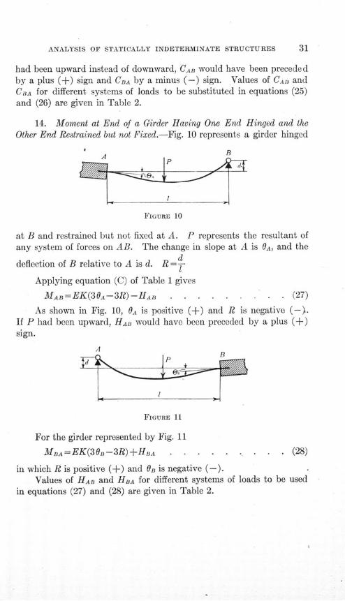
14. Moment at End of a Girder Having One End Hingedand the Other End Restrained but not Fixed . 31
1
CONTENTS
V. CONTINUOUS GIRDERS . . . . . . . . . . . 32
15. Girder Continuous over Any Number of Supports andCarrying Any System of Vertical Loads. SupportsAll on the Same Level. General Equation of ThreeMoments-Two Intermediate Spans . . . . 32
16. Girder Continuous over Any Number of Supports andCarrying Any.System of Vertical Loads. SupportsAll on the Same Level. General Equation ofThree Moments-Two Adjacent Spans at One End.End of Girder Hinged . . . . . . . . . 33
17. Girder Continuous over Any Number of Supports andCarrying Any System of Vertical Loads. SupportsAll on the Same Level. General Equation of ThreeMoments-Two Adjacent Spans at One End. Endof Girder Restrained . . . . . . . . . 34
18. Girder Continuous over Any Number of Supportsand Carrying Any System of Vertical Loads. Sup-ports All on the Same Level. General Equa-tion of Three Moments-Girder Fixed at the Ends 35
19. Girder Continuous over Three Supports and CarryingAny System of Vertical Loads. Supports on Differ-ent Levels. General Equation of Three Moments 35
20. Girder Continuous over Three Supports and CarryingAny System of Vertical Loads. Supports on Differ-ent Levels. Various Conditions of Restraint ofEnds . . . . . . . . . . . . . 37
21. Girder Continuous over Four Supports and CarryingAny System of Vertical Loads. Supports on Differ-
. ent Levels. Various Conditions of Restraint ofEnds . . . . . . . . . . . . . 37
VI. TWO-LEGGED RECTANGULAR BENT. LEGS OF EQUAL LENGTH 49
22. Two-legged Rectangular Bent. Concentrated Hori-zontal Force at the Top-Legs Hinged at the Bases 49
23. Two-legged Rectangular Bent. Concentrated Hori-zontal Force at the Top-Legs Fixed at the Bases 50
24. Two-legged Rectangular Bent. Any System of Hori-zontal Loads on One Leg-Legs Hinged at theBases . . . . . . . . . . . . . 54
CONTENTS
25. Two-legged Rectangular Bent. Any System of Hori-zontal Loads on One Leg-Legs Fixed at the Bases 55
26. Two-legged Rectangular Bent. Any System ofVertical Loads on the Top-Legs Hinged at theBases . . . . . . . . . . . . . 58
27. Two-legged Rectangular Bent. Any System ofVertical Loads on the Top-Legs Fixed at the Bases 59
28. Two-legged Rectangular Bent. External Moment atOne Corner-Legs Hinged at the Bases . . . . 62
29. Two-legged Rectangular Bent. External Momentat One Corner-Legs Fixed at the Bases . . . 63
30. Two-legged Rectangular Bent. Settlement of Foun-dations-Legs Hinged at the Bases . . . . . 65
31. Two-legged Rectangular Bent. Settlement of Foun-dations-Legs Restrained at the Bases . . . 67
VII. TWO-LEGGED RECTANGULAR BENT. ONE LEG LONGER
THAN THE OTHER . . . . . . . . . 71
32. Two-legged Rectangular Bent. One Leg Longer thanthe Other. Concentrated Horizontal Load at Topof Bent-Legs Hinged at the Bases . . . . . 71
33. Two-legged Rectangular Bent. One Leg Longer thanthe Other. Concentrated Horizontal Load at Topof Bent-Legs Fixed at the Bases . . . . . 72
34. Two-legged Rectangular Bent. One Leg Longer thanthe Other. Any Horizontal Load on Vertical Leg-Legs Hinged at the Bases . . . . . . . 75
35. Two-legged Rectangular Bent. One Leg Longer thanthe Other. Any Horizontal Load on Vertical Leg-Legs Fixed at the Bases . . . . . . . . 78
36. 'wo-legged Rectangular Bent. One Leg Longer thanthe Other. Any System of Vertical Loads on Topof Bent-Legs Hinged at the Bases . . . . . 81
37. Two-legged Rectangular Bent. .One Leg Longer thanthe Other. Any System of Vertical Loads on Topof Bent-Legs Fixed at the Bases . . . . . 83
38. Two-legged Rectangular Bent. One Leg Longer thanthe Other. External Moment at One Corner-LegsHinged at the Bases . . . . . . . . . 86
CONTENTS
39. Two-legged Rectangular Bent. One Leg Longer thanthe Other. External Moment at One Corner-Legs Fixed at the Bases . . . . . . . . 87
40. Two-legged Rectangular Bent. One Leg Longer thanthe Other. Settlement of Foundations-LegsHinged at the Bases . . . . . . . . . 89
41. Two-legged Rectangular Bent. One Leg Longer thanthe Other. Settlement of Foundations-Legs Fixedat the Bases . . . . . . . . . . 90
VIII. TWO-LEGGED TRAPEZOIDAL BENTS. BENTS AND LOADING
SYMMETRICAL ABOUT VERTICAL CENTER LINE . . 9442. Two-legged Trapezoidal Bent. Bent and Load Sym-
metrical about Vertical Center Line. VerticalLoad on Top-Legs Hinged at the Bases . . . 94
43. Two-legged Trapezoidal Bent. Bent and Load Sym-metrical about Vertical Center Line. VerticalLoad on Top-Legs Fixed at the Bases . . . . 95
44. Two-legged Trapezoidal Bent. Bent and Loads Sym-metrical about Vertical Center Line. Loads Nor-mal to Legs of Bent-Legs Hinged at the Bases . . 95
45. Two-legged Trapezoidal Bent. Bent and' LoadsSymmetrical about Vertical Center Line. LoadsNormal to Legs of Bent-Legs Fixed at the Bases 96
46. Two-legged Trapezoidal Bent. Bent and Loads Sym-metrical about Vertical Center Line. ExternalMoments at Upper Corners of Bent-Legs Hingedat the Bases . . . . . . . . . . . 97
47. Two-legged Trapezoidal Bent. Bent and Loads Sym-metrical about Vertical Center Line. ExternalMoments at Upper Corners of Bent-Legs Fixedat the Bases ... . . . . . . . 98
IX. RECTANGULAR FRAMES . . . . . . . . . . . 9948. Rectangular Frame. Horizontal Force at the Top . 9949. Rectangular. Frame. Any System of Horizontal
Forces on One Vertical Side . . . . . . . 10250. Rectangular Frame. Any System of Vertical Forces
on the Top . . . . . . . . . . .. 10551. Rectangular Frame. External Moment at Upper
Corner . . . . . . . . .. . .. . 109

CONTENTS
X. MOMENTS IN FRAMES COMPOSED OF A LARGE NUMBER OF
RECTANGLES AS A SKELETON-CONSTRUCTION BUILD-
ING FRAME . . . . . . . . . . . . 113
52. Effect of Restraint at One End of a Member uponMoment at Other End . . . . . . . . 113
53. Moment in a Frame Composed of a Number of Rec-tangles Due to Vertical Loads . . . . . . 116
54. Extremities of Members Hinged . . . . . . 11855. Extremities of Members Fixed . . . . . . 11956. Distribution of Loads for Maximum Moments in a
Frame Composed of a Large Number of Rectangles 12157. Eccentric Load at Top of Exterior Column of a Frame.
Connections of Girders to Columns Hinged . . . 12458. Eccentric Load at Top of Exterior Column of a Frame.
Connections of Girders to Columns Rigid . . . 12959. Eccentric Load at Middle Floor Level of Exterior
Column of a Frame. Connections of Girders toColumns Hinged . . . . . . . . . . 133
60. Eccentric Load at Middle Floor Level of ExteriorColumn of a Frame. Connections of Girders toColumns Rigid . . . . . . . . . . . 136
61. Effect of Settlement of One Column of a Frame Com-posed of a Number of Rectangles . . . . . 142
XI. THREE-LEGGED BENT . . . . . . . . . . . 14762. Three-legged Bent. Lengths of All Legs Different.
Vertical Load on Left-hand Span-Legs Hingedat the Bases . . . . . . . . . . . 147
63. Three-legged Bent. Lengths of All Legs Different.Vertical Load on Left-hand Span-Legs Fixed atthe Bases . . . . . . . . . . . . 149
64. Three-legged Bent. Lengths of All Legs Different.Any System of Loads . . . . . . . . . 150
65. Three-legged Bent. Lengths and Sections of All LegsEqual. Lengths and Sections of Top Members
Equal. Any System of Loads. Let of a Top
IMember be n times of a Leg-Legs Hinged at the
Bases
CONTENTS
66. Three-legged Bent. Lengths and Sections of AllLegs Equal. Lengths and Sections of Top Mem-bers Equal. Any System of Loads-Legs Fixed atthe Bases . . . . . . . . . . . . 163
XII. EFFECT OF ERROR IN ASSUMPTIONS . . . . . . . 18167. Error Due to Assumption that Axial Deformation is
Zero . . . . . . . . . . . . . . 18168. Error Due to Assumption that Shearing Deformation
is Zero . .. . . . . . . . . . . . 18769. Effect of Slip in the Connections upon the Moments
in a Rectangular Frame Having a Single Hori-zontal Force at the Top . . . . . . . . 194
XIII. NUMERICAL PROBLEMS . . . . . . . . . . . 199
70. Girder Restrained at the Ends. Supports on DifferentLevels. Any System of Vertical Loads . . . 199
71. Girder Continuous over Four Supports. Supports onDifferent Levels. Any System of Vertical Loads . 200
72. Girder Continuous over Five Supports. Supports onDifferent Levels. Any System of Vertical Loads.Ends of Girder Restrained . . . . . . . 202
73. Two-legged Rectangular Bent with Legs Fixed at theBases. Bent and Loading Symmetrical about aVertical Center Line . . . . . . . . . 204
74. Two-legged Rectangular Bent. One Leg Longer thanthe Other. Concentrated Horizontal Load at theTop. Legs Fixed at the Bases . . . . . . 205
75. Two-legged Rectangular Bent. Settlement of Foun-dation . . . . . . . . . . . . .. 207
76. Three-legged Bent. Lengths of All Legs Different.Loads on Top and Settlement of Foundations . . 208
XIV. CONCLUSIONS . . . . . . . . . . . . . 212
LIST OF TABLES 7
NO. PAGE
1. General Equations for the Moments at the Ends of a Member AB inFig. 6 . . . . . . . . . . . . . . . . . . . 20
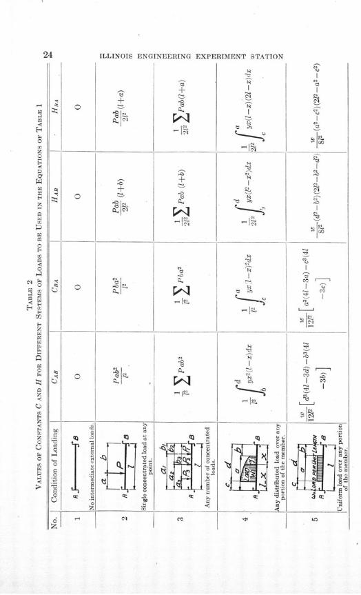
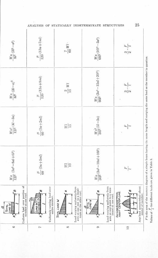
2. Values of Constants C and H for Different Systems of Loads to be Usedin the Equations of Table 1 . . . . . . . . . . . . 24, 25
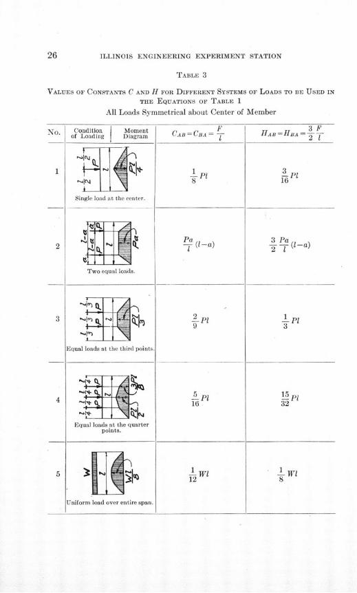
3. Values of Constants C and H for Different Systems of Loads to be Usedin the Equations of Table 1 . . . . . . . . ... . 26, 27
4. Continuous Girders ..... . . . . . . . . . . 385. Girder Continuous over Three Supports . . . . . . . . . 40, 41
6. Girder Continuous over Four Supports . . . . . . . . . 42-477. Equations for the Two-legged Rectangular Bent of Fig. 28 . . . . 578. Equations for the Two-legged Rectangular Bent Represented by Fig. 30 . 619. Equations for the Moments in the Rectangular Bent Represented by
Fig. 39 . . . . . . . .. . . . . . . . . . . . 7910. Equations for the Moments in the Rectangular Bent Represented by
Fig. 42 . . . . . . . . . . . . . . . . . . .. 84
11. Equations for Rectangular Frame with Horizontal Force at the Top . . 101
12. Equations for the Moments in the Rectangular Frame Represented byFig. 54 . ... . . . . . . . . . . . . . .. . 103
13. Equations for the Moments in the Rectangular Frame Represented byFig. 55 . . . . . . . . .. . . . . . . . . . . 106
14. Equations for the Moments in the Rectangular Frame Represented byFig. 56 . . . . . . . . . . . . . . . .. . 110
15. Moments in Frame Represented by Fig. 61 . . . . . . . . . 121
16. Moments in Frame Represented by Fig. 62 . . . . . . . . . 126
17. Moments in a Frame Composed of a Number of Rectangles, Due to Settle-
ment of One Column .... . . . . . . . . 146
18. Equations for Three-legged Bent ... . . . . . . . . 149
19. Equations for Three-legged Bent . . . . . . . . .. . . . 151
20. Fundamental Equations for Three-legged Bents . . . . . . 152, 153
21. Fundamental Equations for Three-legged Bents . . . . . 156, 157
22. Equations for Three-legged Bent .... . . . . . . . 160
23. Equations for Three-legged Beft . . . .. . . . . . . 161
24. Fundamental Equations for Three-legged Bent . . . . . . 164, 165
25. Equations for Three-legged Bent . . . . . . . . . . . . 166
26. Moments Due to Various Systems of Loads on a Three-legged Bent 167-170
27. Fundamental Equations for Three-legged Bent . . . . . . 172, 173
28. Equations for Three-legged Bent . . . . . . . . . . . . 175
29. Moments Due to Various Systems of Loads on a Three-legged Bent 177-180
30. Error in Stresses in Rectangular Frames Due to Neglecting Axial Deforma-
tion . . . . . . . . . . . . . . . . . . . 187
31. Error in Stresses in Rectangular Frames Due to Neglecting Shearing
Deformations . . . . . . . . . . . . . . . . 193
32. Equations for the Three-legged Bent of Fig. 112 . . . . . . . . 210
33. Moments in Three-legged Bent of Fig. 112 . . . . . . . . . 211

ANALYSIS OF STATICALLY INDETERMINATE STRUCTURES
BY THE SLOPE DEFLECTION METHOD
I. PRELIMINARY
1. Object and Scope of Investigation.-Frames composed of rec-tangular elements must in general be designed with stiff connectionsbetween the members at the joints, in order that loads may be carried.These connections must be capable of transferring not only directaxial tensile and compressive forces, but also bending moments. Itfollows that frames made up of rectangular elements are usually stat-ically indeterminate; that is, the stresses in them can be found onlyby taking into account" the relative stiffness and deformations of thevarious members. The common use of rectangular frames in engi-neering structures makes it highly desirable that the most convenientmethods of analyzing their stresses should be developed. The stressesin a number of such rectangular frames have been analyzed by thewriters. This bulletin describes the methods used and presents theformulas derived.
The bulletin is divided into two parts: the first part is devotedto the derivation of fundamental equations; in the second part, methodsand equations are derived for use in determining moments, stresses,and deflections for a variety of typical structures.
2. Acknowledgments.-The investigation here reported was madeunder the auspices of the Department of Civil Engineering of whichDR. F. H. NEWELL is the head. A portion of the work was done in 1915in connection with the development of a thesis in partial fulfillment ofthe requirements for the degree of Master of Science in Civil Engineeringby F. E. RICHART. Many of the analyses have been checked byW. L. PARISH, graduate student in Architectural Engineering, andYi Liu, graduate student in Civil Engineering, to whom the authorsgratefully acknowledge their indebtedness.
ILLINOIS ENGINEERING EXPERIMENT STATION
PART I
DERIVATION OF FUNDAMENTAL EQUATIONS
II. PROPOSITIONS UPON WHICH FUNDAMENTAL EQUATIONS
ARE BASED
3. Statement of Propositions.-The fundamental equations usedin these investigations are derived from the principal propositions ofthe moment-area method.* These may be expressed as follows:
(1) When a member is subjected to flexure, the difference in theslope of the elastic curve between any two points is equal in magnitude
Mto the area of the E diagram for the portion of the member between the
two points.
(2) When a member is subjected to flexure, the distance of anypoint Q on the elastic curve, measured normal to initial position of mem-ber, from a tangent drawn to the elastic curve at any other point P is equal
Min magnitude to the first or statical moment of the area of the l diagram
between the two points, about the point Q.
MThe E- diagram is a graph in which the ordinate at any point is
obtained by dividing the resisting moment, M, by the product ofmodulus of elasticity of material, E, and the moment of inertia of thesection, I, at that point. If E and I are constant, the diagram willbe similar in shape to the moment diagram for the member.
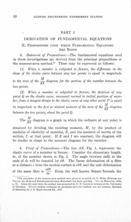
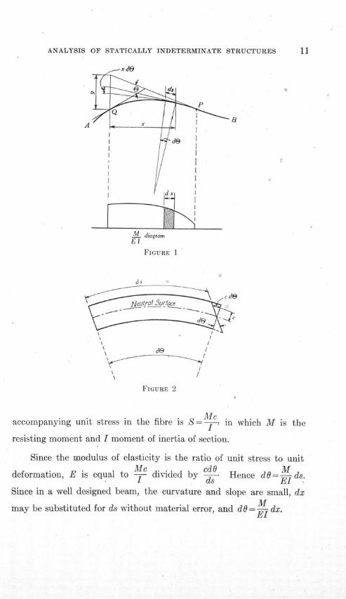
4. Proof of Propositions.-The line AB, Fig. 1, represents theelastic curve of a member in flexure. Consider the elementary length,ds, of the member shown in Fig. 2. The angle between radii at theends of ds will be denoted by dO. The linear deformation of a fibreat a distance c from the neutral surface is cdO, and the unit deformation
cdOof the same fibre is -W- From the well known flexure formula the
*The principles of the moment-area method were given in an article by 0. Mohr, Beitraege zurTheorie der Holz-und Eisenkonstruktionen, Zeitschrift des Arch.-und Ing. Ver. zu Hannover, 1868,p. 19. About the same time the method was presented by C. E. Greene in lectures at the Universityof Michigan. Several modern textbooks on mechanics give the method; see, for instance, Strengthof Materials, by J. E. Boyd, Second Ed., 1917.
ANALYSIS OF STATICALLY INDETERMINATE STRUCTURES
FIGURE 1
Ss
N^^ teatrqf_5yurfac ~~~:
* /
\, /
d /de
FIGURE 2
Meaccompanying unit stress in the fibre is S= , in which M is the
resisting moment and I moment of inertia of section.
Since the modulus of elasticity is the ratio of unit stress to unitMc cdO M
deformation, E is equal to -- divided by -- Hence dO=-ds.I ds El
Since in a well designed beam, the curvature and slope are small, dxMmay be substituted for ds without material error, and dO0=- dx.T1
I

ILLINOIS ENGINEERING EXPERIMENT STATION
M MIn the E- diagram of Fig. 1, k dx represents the area of the
diagram for the length dx. The area of the diagram between points
P MQ and P on the elastic curve is then equal to El dx. But the differ-
ence of slope of the tangent to the elastic curve is also represented by
0= dO -f - dx . ........ ... . (1)
Hence proposition (1) of the preceding section is proved. It maybe noted that if M is taken as the resisting moment acting on theportion of the member to the left of any section, by applying the
Mconventions of section 5 the area of the E diagram is positive; also
Elthe direction of integration from Q to P is positive, and the differencein slope 0 is positive. Other terms involved may be considered asscalar quantities. These conventions apply to any case, as, for instance,difference in slope from P to Q is negative, since the direction ofintegration is negative.
In Fig. 1 the tangents at the extremities of the element of theelastic curve, ds, are extended until they intersect the vertical linethrough the point Q. The intercept on this vertical line between the.two consecutive tangents is xdO. The total vertical distance, y, of Qfrom the tangent drawn at P is the algebraic sum of all the interceptsbetween tangents for the portion of the curve between Q and P;
that is, y= xdO. Substituting the value of dO found previously,
PIM
y= f ixdx . ...... ...... (2)
M MIn the E- diagram of Fig. 1 , - dx represents the area of the
Mdiagram for the length dx, and - dx times x represents the moment
Mof this area about the point Q. The moment of the entire area of the El
diagram between points Q and P about the point Q may now be ex-

ANALYSIS OF STATICALLY INDETERMINATE STRUCTURES 13
pressed by - xdx. Since this expression is identical with the
right-hand member of equation (2), proposition (2) of the precedingsection is proved. The conventions of section 5 apply here as explainedin the proof of proposition (1).
ILLINOIS ENGINEERING EXPERIMENT STATION
III. DERIVATION OF FUNDAMENTAL EQUATIONS
5. Conventional Signs.-The signs of the quantities used in theequations in this bulletin are determined by the following conventionalrules:
When the tangent to the elastic curve of a member has been turnedthrough a clockwise direction, measured from its initial position, thechange in slope, or the angular deformation, is positive.
When the line joining the ends of a member is rotated, the move-ment of one end of the member relative to the other, measured perpen-dicular to the initial position of member is called a deflection, and isso used throughout the following discussion. The deflection is positivewhen such rotation is in a clockwise direction from the initial positionof member.
The resisting moment or moment of the internal stresses on asection is positive when the internal or resisting couple acts in a clock-wise direction upon the portion of the member considered. According tothis rule the portion of the member considered must always be specified,and will be indicated by the subscripts used with the moments. Forexample, if C is a point on a member between the ends A and B, McAis equal to -MCB.
The moment of an external force or couple is positive if it tendsto cause a clockwise rotation.
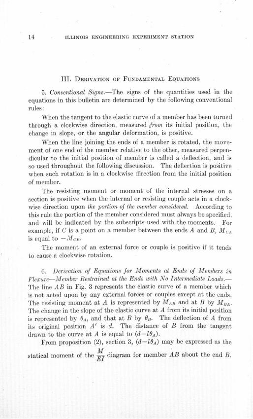
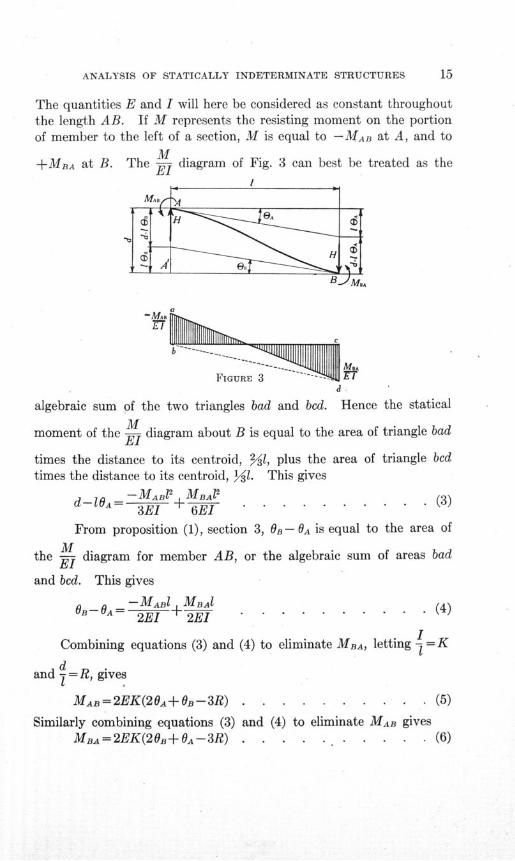
6. Derivation of Equations for Moments at Ends of Members inFlexure-Member Restrained at the Ends with No Intermediate Loads.-The line AB in Fig. 3 represents the elastic curve of a member whichis not acted upon by any external forces or couples except at the ends.The resisting moment at A is represented by MAB and at B by MBA-The change in the slope of the elastic curve at A from its initial positionis represented by OA, and that at B by 0B. The deflection of A fromits original position A' is d. The distance of B from the tangentdrawn to the curve at A is equal to (d-lOA)
From proposition (2), section 3, (d-l0A) may be expressed as the
Mstatical moment of the TY diagram for member AB about the end B.
ANALYSIS OF STATICALLY INDETERMINATE STRUCTURES 15
The quantities E and I will here be considered as constant throughoutthe length AB. If M represents the resisting moment on the portionof member to the left of a section, M is equal to -MAB at A, and to
M+MBA at B. The E diagram of Fig. 3 can best be treated as the
I
Ma
FIGURE 3 --
algebraic sum of the two triangles bad and bed. Hence the statical
moment of the - diagram about B is equal to the area of triangle bad
times the distance to its centroid, 231, plus the area of triangle bedtimes the distance to its centroid, 131. This gives
-MjAB 2 "MiBAl (3d-10a= +M ± 6E . .. ......... (3)
3El 6El
From proposition (1), section 3, OB - OA is equal to the area of
Mthe E- diagram for member AB, or the algebraic sum of areas bad
and bed. This gives
-MABI MB (0.-OA= 2EI + 2EI . .......... (4)
ICombining equations (3) and (4) to eliminate MBA, letting = K
dand I = R, gives
MAB=2EK(20A+OB-3R) . . . . . . .. . . (5)
Similarly combining equations (3) and (4) to eliminate MAB givesMBA=2EK(20B+0A-3R) . . . . . . . . . . (6)
ILLINOIS ENGINEERING EXPERIMENT STATION
Since the signs of all quantities in equations (3) and (4) are independentof the sense of the quantities themselves it follows that equations (3)and (4) are general; and they give the sense as well as magnitude of themoments, no matter what the senses of OA, OB, and R may be, provided themethod of determining signs given in section 5 is followed. As beforenoted, MAB is the resisting moment acting at the end A of the memberAB. The moment which AB exerts upon the support at A is equalin magnitude but opposite in sense to MAB. A and B are not neces-sarily supports of a member but may be any two points along thelength of a member, provided there is no intermediate load on themember between them.
AElE9
(c)
FIGURE 4
Equations (5) and (6) are fundamental equations.* They may beexpressed as follows: -The moment at the end of any member carryingno intermediate loads is equal to 2EK times the quantity: Twice thechange in slope at the near end plus the change in slope at the far endminus three times the ratio of deflection to length. E is the modulus
*The slope-deflection equations for a member acted upon only by forces and couples at the endswere deduced by Manderla in 1878. See Annual Report of the Technische Hochschule, Munich,1879, and AUgemeine Bauzeitung, 1880. The use of these equations has been developed by severalwriters, among whom are:
Mohr, Otto, "Abhandlungen aus dem Gebiete der Technischen Mechanik," Second Ed., 1914.Kunz, F. C. "Secondary Stresses," Engineering News, Vol. 66, p. 397, Oct. 5, 1911.Wilson and Maney, "Wind Stresses in the Steel Frames of Office Buildings," Univ. of Ill. Eng.
Exp. Sta., Bul. 80, 1915.
ANALYSIS OF STATICALLY INDETERMINATE STRUCTURES
of elasticity of the material, and K is the ratio of moment of inertiato length of member.
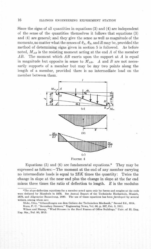
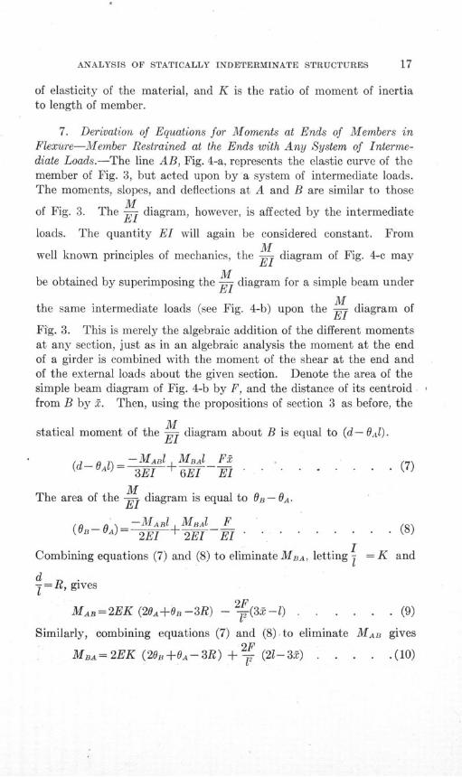
7. Derivation of Equations for Moments at Ends of Members inFlexure-Member Restrained at the Ends with Any System of Interme-diate Loads.-The line AB, Fig. 4-a, represents the elastic curve of themember of Fig. 3, but acted upon by a system of intermediate loads.The moments, slopes, and deflections at A and B are similar to those
Mof Fig. 3. The E diagram, however, is affected by the intermediate
loads. The quantity El will again be considered constant. FromM
well known principles of mechanics, the E diagram of Fig. 4-c may
Mbe obtained by superimposing the T diagram for a simple beam under
Mthe same intermediate loads (see Fig. 4-b) upon the E diagram of
Fig. 3. This is merely the algebraic addition of the different momentsat any section, just as in an algebraic analysis the moment at the endof a girder is combined with the moment of the shear at the end andof the external loads about the given section. Denote the area of thesimple beam diagram of Fig. 4-b by F, and the distance of its centroidfrom B by 2. Then, using the propositions of section 3 as before, the
Mstatical moment of the El diagram about B is equal to (d- OA-).
O)= -MARl MBAl F2(d- 3E + 6E1 . ... . . . . (7)
MThe area of the E- diagram is equal to O- OA-
-MABI MBAl F(OB-OA)-I E .M . . . . .(8)
2E - 2E1 El.. ......
Combining equations (7) and (8) to eliminate MBA, letting =K and
d= R, gives
MAB=2EK (20A+OB-3R) - 2F(3-l) . . . . . . (9)
Similarly, combining equations (7) and (8) to eliminate MAB givesMBA2F (2- ) (10)
MA= 2EK (20B+0A--3R) +- (2l-3- ) . . . . .(10)
ILLINOIS ENGINEERING EXPERIMENT STATION
It is seen that equations (9) and (10) are identical with equations (5)and (6) except that they contain an additional term in the right-handmembers of the equations. This additional term is independent ofthe slopes and deflections of the member, and depends solely upon theintermediate loads. Further significance is given to this term if theslopes and deflections are made equal to zero, as is true in a fixed beamwith supports on same level. The last term then becomes the resistingmoment acting on the end of the fixed beam. Hence it is seen thatin general the resisting moment at the end of a member with any systemof intermediate loads can be expressed as the algebraic sum of the resistingmoment at the end of a member with no intermediate loads, as given byequations (5) and (6), and the resisting moment at the end of a fixedbeam with an equal span and carrying the same system of intermediateloads.
If the resisting moment at the end of a fixed beam with supportson same level be expressed by C, with subscripts similar to those usedfor moments, M, equations (9) and (10) may be written in the followinggeneral form
MAB=2EK(20A+ OB-3R) -CAB. . ... .. . (11)
MBA=2EK(20e+OA-3R)+CBA . . . . . . . . (12)
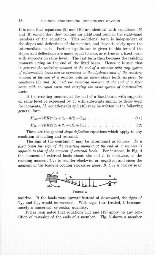
These are the general slope deflection equations which apply to anycondition of loading and restraint.
The sign of the constant C may be determined as follows: In afixed beam the sign of the resisting moment at the end of a member isopposite to that of the moment of external loads. For instance, in Fig. 4the moment of external loads about the end A is clockwise, so theresisting moment CAB is counter clockwise or negative; and since themoment of the loads is counter clockwise about B, CBA is clockwise or
FIGURE 5
positive. If the loads were upward instead of downward, the signs ofCAB and CBA would be reversed. With signs thus treated, C becomesmerely a numerical, or scalar, quantity.
It has been noted that equations (11) and (12) apply to any con-dition of restraint of the ends of a member. Fig. 5 shows a member
ANALYSIS OF STATICALLY INDETERMINATE STRUCTURES
restrained at A and hinged to the support at B, so that the resistingmoment at B is zero. Equations (11) and (12) may be written:
MAB = 2EK(2 0A + OB - 3R) - CAB0 = MBA = 2EK(20 + 0A-3R) +CBA
Combining these two equations to eliminate OB gives
MAB=EK(30A-3R)-(CAB+C ) . . . . . . . (13)
If the beam is fixed at A and hinged at B, with the supports on thesame level, OA and R in equation (13) are zero, and therefore the term
- (CAB+ ' ) represents the resisting moment at the end A, and can
be readily calculated for any given loading.
By similar reasoning, when a beam is restrained at the end B andhinged to support at A, it is found that
MBA=EK(30B-3R)+(CBA+ C B ) . . . . . . . (14)
For more convenient reference let the quantity (CAB+ C-A) be
denoted by HAB, and the quantity (CBA+ C ) by HBA.
Equations (13) and (14) then take the general form
MAB=EK(30A-3R)-HAB . . . . . . . . (15)
MBA= EK(3Bs-3R)+HBA . . . . . .. . . . (16)
The term H represents the resisting moment at the fixed end ofa beam which is fixed at one end and hinged to the support at the other,with supports at same level. The sign of H is determined in the sameway as the sign of C in equations (11) and (12). That is, the sign of His always opposite to the sign of the moment of the external loadsabout the fixed end of the member. If the external loads act upwardinstead of downward, the values of H in equations (15) and (16) mustbe reversed.
Equations (11) and (12) are the general equations for the ends ofa member in flexure. Equations (15) and (16) are special forms ofequations (11) and (12), applicable to members having one end hinged.
For convenience in reference these four equations are given in Table 1
where they are denoted as equations (A), (B), (C), and (D), respec-tively.
ILLINOIS ENGINEERING EXPERIMENT STATION
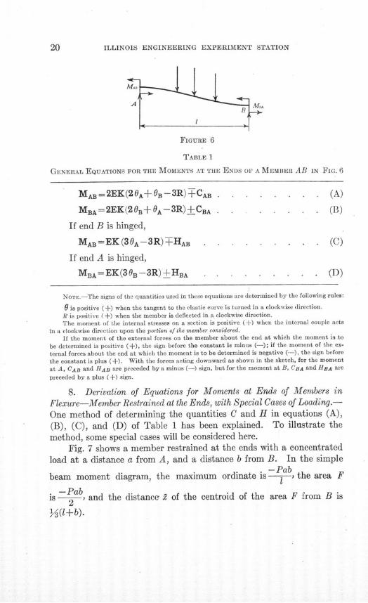
FIGURE 6
TABLE 1
GENERAL EQUATIONS FOR THE MOMENTS AT THE ENDS OF A MEMBER AB IN FIG. 6
MAB= 2 EK( 2 0A+ B- 3 R) CAB . . . . . . . . (A)
MBA= 2 EK(2 0B+0A- 3 R) ±CBA . . . . . . (B)
If end B is hinged,
MAB=EK( 3 0 A- 3 R) HAB . . . . . . . . (C)
If end A is hinged,
MBA= EK( 3 0 B - 3 R)±HBA . . ..... . . . . (D)
NOTE.-The signs of the quantities used in these equations are determined by the following rules:
0 is positive (+) when the tangent to the elastic curve is turned in a clockwise direction.
R is positive (+) when the member is deflected in a clockwise direction.
The moment of the internal stresses on a section is positive (+) when the internal couple acts
in a clockwise direction upon the portion of the member considered.
If the moment of the external forces on the member about the end at which the moment is to
be determined is positive (+), the sign before the constant is minus (-); if the moment of the ex-
ternal forces about the end at which the moment is to be determined is negative (-), the sign before
the constant is plus (+). With the forces acting downward as shown in the sketch, for the moment
at A, CAB and HAB are preceded by a minus (-) sign, but for the moment at B, CBA and HBA are
preceded by a plus (+) sign.
8. Derivation of Equations for Moments at Ends of Members in
Flexure-Member Restrained at the Ends, with Special Cases of Loading.-
One method of determining the quantities C and H in equations (A),(B), (C), and (D) of Table 1 has been explained. To illustrate themethod, some special cases will be considered here.
Fig. 7 shows a member restrained at the ends with a concentratedload at a distance a from A, and a distance b from B. In the simple
- Pabbeam moment diagram, the maximum ordinate is 1 , the area F
is -Pab, and the distance 2 of the centroid of the area F from B is
Y (l+b).
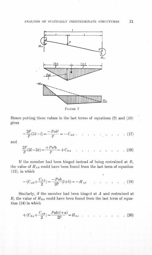
ANALYSIS OF STATICALLY INDETERMINATE STRUCTURES
FIGURE 7
Hence putting these values in the last terms of equationsgives
2F - Pab21 (32- l)1 )- CA .- .
(9) and (10)
(17)
2F +Pa 2b., (21-32)-= 12 +±CBA
If the member had been hinged instead of being restrained at B,the value of HAB could have been found from the last term of equation(13), in which
Cn=-W Pab-(CAB+ 2)= __j(1+b)= -HAB . . . . (19)
Similarly, if the member had been hinged at A and restrained atB, the value of HBA could have been found from the last term of equa-tion (14) in which
+ (CB,+ ) = Pab(l+a)=H. (20)+(CB+ 2 21, =HBA . . . . . . . . (20)
. (18)
1 +a _ __
*]Ph3Sfl|PIII
ILLINOIS ENGINEERING EXPERIMENT STATION
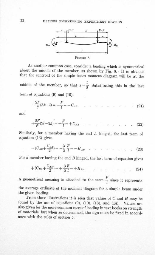
FIGURE 8
As another common case, consider a loading which is symmetricalabout the middle of the member, as shown by Fig. 8. - It is obviousthat the centroid of the simple beam moment diagram will be at the
1middle of the member, so that t= . Substituting this in the last
term of equations (9) and (10),
2F(3.-l) F2CAB . . * . . . . . . (21)
and
2F F+ -(21- 3) = -+ = +BA . . . . . . . . (22)
Similarly, for a member having the end A hinged, the last term ofequation (13) gives
-(CAB+ )=- _ =-H . ....... (23)
For a member having the end B hinged, the last term of equation gives
+(CBA+ C )=+ = +HBA . . . . . . . (24)
A geometrical meaning is attached to the term - since it represents
the average ordinate of the moment diagram for a simple beam underthe given loading.
From these illustrations it is seen that values of C and H may befound by the use of equations (9), (10), (13), and (14). Values arealso given for the more common cases of loading in text books on strengthof materials, but when so determined, the sign must be fixed in accord-ance with the rules of section 5.
ANALYSIS OF STATICALLY INDETERMINATE STRUCTURES
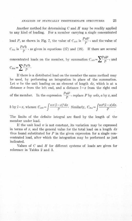
Another method for determining C and H may be readily appliedto any kind of loading. For a member carrying a single concentrated
Pab2load P, as shown in Fig. 7, the value of CAR is 2 , and the value of
Pa2bCBA is -2 as given in equations (17) and (18). If there are several
Pab2concentrated loads on the member, by summation CAB 1= 12 and
CA = Pa 2bCBA - E 12
If there is a distributed load on the member the same method maybe used, by performing an integration in place of the summation.Let w be the unit loading on an element of length dx, which is at adistance x from the left end, and a distance 1-x from the right end
Pab2of the member. In the expression 12 > replace P by wdx, a by x, and
b by l-x, whence CAB 2 wx(- x ) dx . Similarly, CBA=f 2( x ) d x
The limits of the definite integral are fixed by the length of themember under load.
If the unit load w is not constant, its variation may be expressedin terms of x, and the general value for the total load on a length dxthus found substituted for P in the given expression for a single con-centrated load, after which the integration may be performed as justindicated.
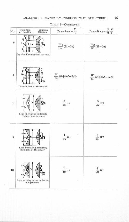
Values of C and H for different systems of loads are given forreference in Tables 2 and 3.
ILLINOIS ENGINEERINO EXPERTMENT SmATTON
A
0
B
0
0
0
E-)
0
U)
z
0
u
PR
0C
0
o?
Z*
isC?
Hoao
?;
ILLINOIS ENGINEERING EXPERIMENT STATION
ANALYSIS OF STATICALLY INDETERMINATE STRUCTURES
5,
'~ .~
4) "050~
CC 4)
0~4~4) 0
0444)4)
V, I-co 0cq
0
0
30
O0
4)
I0
§)
.0
0).a
&Ca
.c3
o*~4)m5aS
4)c3
o3
0 r4)Q-
ILLINOIS ENGINEERING EXPERIMENT STATION
TABLE 3
VALUES OF CONSTANTS C AND H Fon DIFFERENT SYSTEMS OF LOADS TO BE USED IN
THE EQUATIONS OF TABLE 1
All Loads Symmetrical about Center of Member
MomentDiagram
Single load at the center.
2 equal loads.
Two equal loads.
CA = CBA= T
Pa (1-a)S1
5 Pl16
1 W112
HAB=HBA = -T
3 Pa2 T( 1 -a)
Pl3
15 Pl32
1 Wl8
ANALYSIS OF STATICALLY INDETERMINATE STRUCTURES
TABLE 3-CONTINUED
Wa (31-2a)121
- (12+2al-2a2)
5 w
116
1 ll- W10 "
a (31-2a)81
- (12 +2al-2a2)81
5- Wl32
W1
3 w l
ILLINOIS ENGINEERING EXPERIMENT STATION
PART II
DETERMINATION OF STRESSES IN STATICALLY INDE-
TERMINATE STRUCTURES
9. Assumptions upon which the Analyses are Based.-The analysesin this bulletin are based upon the following assumptions:
(1) That the connections are perfectly rigid.(2) That the length of a member is not changed by axial stress.(3) That the shearing deformation is zero.
Recent tests by Abe* show that the first assumption is approxi-mately true for reinforced concrete frames, and tests by Wilson andMooret show that this assumption is also approximately true for certaintypes of riveted connections of steel frames.
The error due to assumptions (2) and (3) depends upon the geo-metrical properties of the frame, but for frames of usual proportionsthe error is not large. These assumptions are discussed in detail insections 67 and 68. The error due to slip in connections is discussedin section 69.
10. Notation.-The following notation has been used:a = distance from end A of a member to a load.b= distance from end B of a member to a load.d= deflection of one end of a member with respect to the other
end, measured perpendicular to initial position of member.e= eccentricity of load.h = vertical height of a structure.k = error in resisting moment due to neglect of shearing strain.
= length of a member.m = change in the rate of loading in a unit distance.n = ratio of K of top member to K of left-hand column for a four-
sided frame.p = ratio of K of top member to K of bottom member for a four-
sided frame.
*Abe, Mikishi, "Analysis and Tests of Rigidly Connected Reinforced Concrete Frames," Univ.
of Ill. Eng. Exp. Sta., Bul. 107, 1918.tWilson, W. M., and Moore, H. F., "Tests to Determine the Rigidity of Riveted Joints of Steel
Structures," Univ. of Ill. Eng. Exp. Sta., Bul 104, 1917.
ANALYSIS OF STATICALLY INDETERMINATE STRUCTURES
q = ratio of the length of the left-hand column to the length of theright-hand column of a two-legged bent.
s = ratio of K of top member to K of right-hand column for a four-sided frame.
u = load per unit of length (variable).w = uniformly distributed load per unit of length.A = area of section of a member.
CAB= resisting moment at end A of a member AB fixed at both endsand having both ends at the same level.
E = modulus of elasticity in tension and compression.F = area of the moment diagram of a simple beam.G =modulus of elasticity in shear.H = reaction.
HA = resisting moment at end A of a member AB fixed at A andhinged at B and having both ends at the same level.
I = moment of inertia of section of a member.K = ratio of moment of inertia of section to length of a member.M= moment of an external couple. I
MA = statical moment of external forces about point A.MAB =resisting moment acting at the end A of a member AB.MBA = resisting moment acting at the end B of a member AB.
N= restraint factor, depending on manner in which the ends of amember are held.
P = concentrated load.d
R = -= ratio of the deflection of one end of a member (with respect
to the other end) to the length of the member.S = shear.
W = total distributed load on a member.a = n2+ 2pn + 2n+3p, for a symmetrical four-sided frame.0i= 6n+p+ 1, for a symmetrical four-sided frame.A = 22(pns+ps+ns+np) +2(p2s+ps2+pn2+p 2n+s+ss+n2+n) +
6(n2s+ns2+p 2+p), for a rectangular frame.
Ao= 2[ns(4+3q+4q2) + (s2 +s) +q 2(n2 + n) + 3(q2sn2 +s 2n)], for a two-
legged rectangular bent with unequal legs.Ao= 2(3ns2 + 11ns+s 2+ s+3n 2s+n+ n), for a two-legged rectangular
bent.o= change in the slope of the tangent to the elastic curve of a
member.
ILLINOIS ENGINEERING EXPERIMENT STATION
IV. GIRDERS HAVING RESTRAINED ENDS
11. Moments at the Ends of a Girder Having Fixed Ends-BothSupports on the Same Level.-If a girder is fixed at the ends and if bothsupports are on the same level, OA, OB, and R of equations (A) and (B),
Table 1, equal zero. This being the case, MAB = CAn and MBA =
±CBA. Values of CAB and CRA for different systems of loads are given
in Table 2.
FIGURE 9
12. Moments at the End of a Girder Having One End Fixed andthe Other End Hinged, Both Supports on the Same Level.-If a girder isfixed at one end, 0 for that end equals zero. Likewise if both supportsare on the same level, R = 0. This being the case, the moment at thefixed end, as given by equations (C) and (D),Table 1, isTHAB or ±HBA.
Values of HAB and HBA for different systems of loads are given inTable 2.
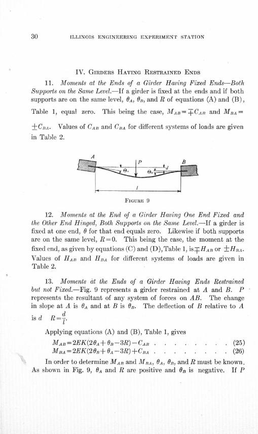
13. Moments at the Ends of a Girder Having Ends Restrainedbut not Fixed.-Fig. 9 represents a girder restrained at A and B. Prepresents the resultant of any system of forces on AB. The changein slope at A is OA and at B is OB. The deflection of B relative to A
is d R= .1*
Applying equations (A) and (B), Table 1, gives
MAB=2EK(20A+OB-3R)-CAB . . . . . . . . (25)MBa=2EK(2OB+OA-3R)+CBA . . . . . . . . (26)
In order to determine MAB and MBA, OA, OB, and R must be known.As shown in Fig. 9, OA and R are positive and OB is negative. If P
ANALYSIS OF STATICALLY INDETERMINATE STRUCTURES
had been upward instead of downward, CAB would have been precededby a plus (+) sign and CBA by a minus (-) sign. Values of CAB andCBA for different systems of loads to be substituted in equations (25)and (26) are given in Table 2.
14. Moment at End of a Girder Having One End Hinged and theOther End Restrained but not Fixed.-Fig. 10 represents a girder hinged
0D
FIGURE 10
at B and restrained but not fixed at A. P represents the resultant ofany system of forces on AB. The change in slope at A is OA, and the
ddeflection of B relative to A is d. R =-
Applying equation (C) of Table 1 gives
MAB=EK(30A-3R)-HAB . . .. . . . .. . (27)
As shown in Fig. 10, OA is positive (+) and R is negative (-).If P had been upward, HAB would have been preceded by a plus (+)sign.
AB
FIGURE 11
For the girder represented by Fig. 11
MBA=EK(30B-3R)+HBA . . . . . . . . . (28)
in which R is positive (+) and OB is negative (-).Values of HAB and HBA for different systems of loads to be used
in equations (27) and (28) are given in Table 2.
n
ILLINOIS ENGINEERING EXPERIMENT STATION
V. CONTINUOUS GIRDERS
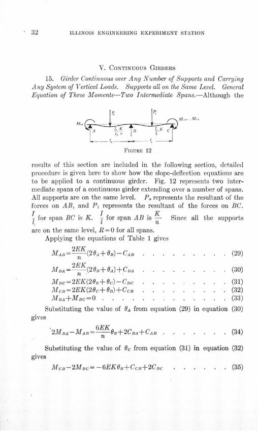
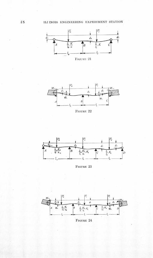
15. Girder Continuous over Any Number of Supports and CarryingAny System of Vertical Loads. Supports all on the Same Level. GeneralEquation of Three Moments-Two Intermediate Spans.-Although the
Ah.
FIGURE 12
results of this section are included in the following section, detailedprocedure is given here to show how the slope-deflection equations areto be applied to a continuous girder. Fig. 12 represents two inter-mediate spans of a continuous girder extending over a number of spans.All supports are on the same level. Po represents the resultant of theforces on AB, and P1 represents the resultant of the forces on BC.I I K1 for span BC is K. I for span AB is -K Since all the supports1 i nare on the same level, R = 0 for all spans.
Applying the equations of Table 1 gives
2EKMAB= --- (20A + B)-CAB ....... . . (29)
2EKMBA=- (20B+GA)+CA.A . . . . . . . . .. (30)
n .MBc=2EK(20B+0c)-CBc . . . . . . . . . (31)McB=2EK(20c+ OB)+CB . . . . . . . . . (32)
MBA+MBC=O . ............ (33)
Substituting the value of OA from equation (29) in equation (30)gives
2MBA-MAB= 6E OB+2CBA+CAB . . . . . . . (34)n
Substituting the value of Oc from equation (31) in equation (32)gives
McB-2MBC= -6EKOB+CcB+2Cnc
S32
M ...- - M ro
. (35)
ANALYSIS OF STATICALLY INDETERMINATE STRUCTURES
Substituting the value of 0n from equation (35) in equation (34),and substituting -MBC for MBA gives
nMAB+2MBc(n+1)+McD=-[n(2CBA +CAB)+ (CcB+2CBc)](36)
In determining the values of C and H given in Table 3, it wasfound that
2CAB+CA 2CBA+CAnHAB=- and HBA=--
2 2
Equation (36) can, therefore, be written in the form
nMAB+2Mic(n+l)+McD= -2[nHBA+Hc] . . . . (37)
This is the general form of the well-known "Equation of ThreeMoments."* It may be applied to a continuous girder having allsupports on the same level, no matter what the type of loading towhich the girder is subjected. As applied to two adjacent spans,
I K IK=- for the right-hand span and K-= for the left-hand span; that is,
I In=- Tfor the right-hand span divided by 1 for the left-hand span.
Values of H for different types of loading are given in Table 2.
16. Girder Continuous over Any Number of Supports and CarryingAny System of Vertical Loads. Supports All on the Same Level. GeneralEquation of Three Moments-Two Adjacent Spans at One End. End
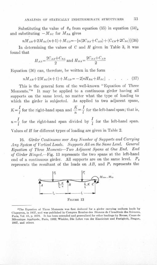
of Girder Hinged.-Fig. 13 represents the two spans at the left-handend of a continuous girder. All supports are on the same level. Porepresents the resultant of the loads on AB, and Pi represents the
M- - MCD
FIGURE 13
*The Equation of Three Moments was first deduced for a girder carrying uniform loads by
Clapeyron, in 1857, and was published in Comptes Rendus des S6ances de l'Acad6mie des Sciences,
Paris, Vol. 45, p. 1076. It has been extended and generalized for other loadings by Bresse, Cours de
M4canique Appliqu6e, Paris, 1862; Winkler, Die Lehre von der Elasticitat und Festigkeit, Prague,
1867, and others.

ILLINOIS ENGINEERING EXPERIMENT STATION
resultant of the loads on BC. The girder is hinged at A. Equation(37), having been derived for the general case, is applicable. As thegirder is hinged at A, MA =O0. Equation (37), therefore, takes theform
2MBc(n+1)+MD= -2[nHBA+HBc] . . . . . . (38)
for two adjacent spans at the left-hand end of the girder when theleft-hand end is hinged. Likewise,
nMAB+2Mc(n+l) = -2 [n HBA+HBc] . . . . . (39)
for two adjacent spans at the right-hand end of the girder when theright-hand end is hinged.
17. Girder Continuous over Any Number of Supports and CarryingAny System of Vertical Loads. Supports All on the Same Level. Gen-eral Equation of Three Moments-Two Adjacent Spans at One End.End of Girder Restrained.-Fig. 14 represents the two spans at the left-
FIGURE 14
hand end of a continuous girder. All supports are on the same level.Po represents the resultant of the loads on AB, and P1 represents theresultant of the loads on BC. The girder is restrained at A.
The values of the moments depend upon the restraint of the pointA, and therefore fhe moments cannot be determined unless either themoment at A or the slope of the elastic curve of the girder at A is known.If the moment at A is known, equation (37) is applicable. If the slopeat A is known, OA is a known quantity.
Substituting the value OB from equation (29) in equation (30)gives
2nMAB =6EKOA-nMBc-2nHAR . . . . . . . (40)
Substituting MAB from equation (40) in equation (37) gives
MBc(4+3n)+2McD= 2n HAB-4(nHBA+HRc) -6EK OA . (41)
Equation (41) is applicable to the two adjacent spans at the left-hand end of a continuous girder restrained at the left-hand end.
ANALYSIS OF STATICALLY INDETERMINATE STRUCTURES
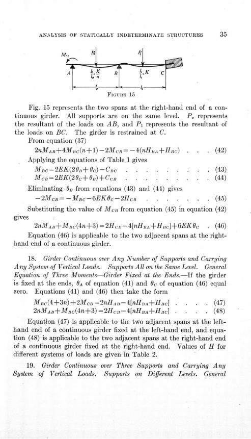
FIGURE 15
Fig. 15 represents the two spans at the right-hand end of a con-tinuous girder. All supports are on the same level. Po representsthe resultant of the loads on AB, and P1 represents the resultant ofthe loads on BC. The girder is restrained at C.
From equation (37)
2nMAB+4MBc(n+l)-2McB= -4(nHuA+±HBc) . . . (42)
Applying the equations of Table 1 gives
Mnc=2EK(20B+OC)-CBc . . . . . . . . . (43)McB=2EK(20c+O)+CcB . . . . . . ........ (44)
Eliminating On from equations (43) and (41) gives
-2Mcn= -MBc-6EKOc-2He .. . . . . . . (45)
Substituting the value of MCB from equation (45) in equation (42)gives
2nMAB+MBc(4n+3)=2HcB--4[nHBA+HBc]+6EKOc . (46)
Equation (46) is applicable to the two adjacent spans at the right-hand end of a continuous girder.
18. Girder Continuous over Any Number of Supports and CarryingAny System of Vertical Loads. Supports All on the Same Level. GeneralEquation of Three Moments-Girder Fixed at the Ends.-If the girderis fixed at the ends, OA of equation (41) and Oc of equation (46) equalzero. Equations (41) and (46) then take the form
Mnc(4+3n)+2McD=2fHnHAB- 4[nHBA+HBc] . . . . (47)
2nMAB+MBc(4n+3)=2Hc,-4[nHBA+HBc] . . . . (48)
Equation (47) is applicable to the two adjacent spans at the left-hand end of a continuous girder fixed at the left-hand end, and equa-tion (48) is applicable to the two adjacent spans at the right-hand endof a continuous girder fixed at the right-hand end. Values of H fordifferent systems of loads are given in Table 2.
19. Girder Continuous over Three Supports and Carrying AnySystem of Vertical Loads. Supports on Different Levels. General
ILLINOIS ENGINEERING EXPERIMENT STATION
Equation of Three Moments.-In section 15, the equations of Table 1
have been used to derive a general "Equation of Three Moments."
The derivation is seen to be merely the combination of four linear
equations involving slopes, deflections, and moments at the supports
for each span into an equation involving the same quantities for any
two adjacent spans.
FIGURE 16
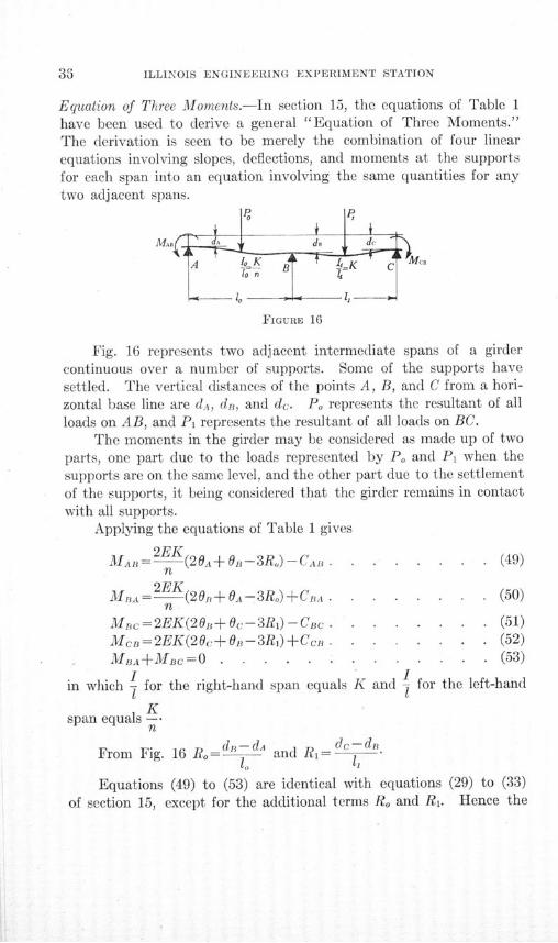
Fig. 16 represents two adjacent intermediate spans of a girdercontinuous over a number of supports. Some of the supports havesettled. The vertical distances of the points A, B, and C from a hori-zontal base line are dA, dB, and dc. Po represents the resultant of allloads on AB, and Pi represents the resultant of all loads on BC.
The moments in the girder may be considered as made up of twoparts, one part due to the loads represented by Po and P1 when thesupports are on the same level, and the other part due to the settlementof the supports, it being considered that the girder remains in contactwith all supports.
Applying the equations of Table 1 gives
MA= 2EK(20A+o -3Ro)-CAI . . . . . . . . (49)n
MBA 2EK(20,+0A-3Ro)+CCA. . . . . . . . (50)n
M.c=2EK(20.+.Oc-3Ri)-CBc. . . . . . .. (51)McB=2EK(20c+10-3R,)+CcI . . . . . . . (52)
MnA+MBC=O . . .... . . . . . . . (53)
I Iin which - for the right-hand span equals K and , for the left-hand
Kspan equals -K
n
From Fig. 16 Ro= d and R 1= -
Equations (49) to (53) are identical with equations (29) to (33)
of section 15, except for the additional terms Ro and Ri. Hence the
ANALYSIS OF STATICALLY INDETERMINATE STRUCTURES
method of solving for the moments is the same as in section 15,
and will not be repeated here in detail. The general equation of three
moments for a continuous girder carrying any system of vertical loads
and with supports on different levels, together with some special forms
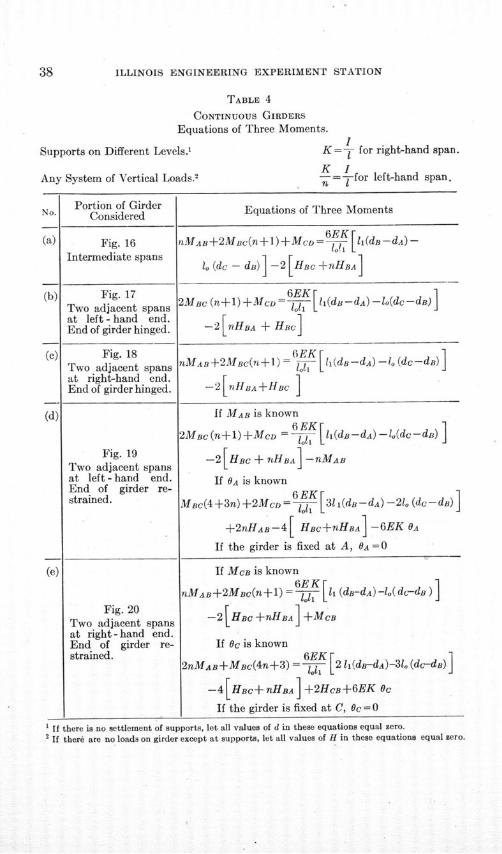
of the equation, are given in Table 4.*
20. Girder Continuous over Three Supports and Carrying Any
System of Vertical Loads. Supports on Different Levels. Various
Conditions of Restraint of Ends.-Table 4, section 19, gives the general
equation of three moments which is to be applied here. Various cases
of restraint of the ends of girder and the effect upon the quantities
in the general equation will be considered. It is seen that if the end
of the girder is hinged, the resisting moment there is zero. If it is
fixed, the slope at that point is zero. If the end is restrained, or par-
tially fixed, the moments at the other supports can be found, if either
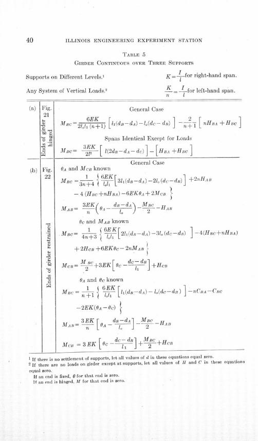
the slope or the moment at the end is known. Modifications of the
equations of Table 4, for these various cases of restraint, are given
in Table 5.
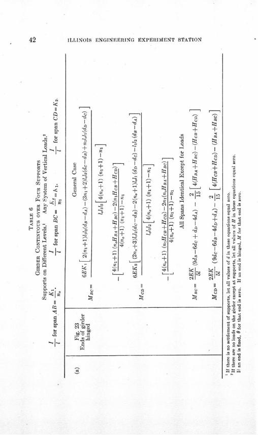
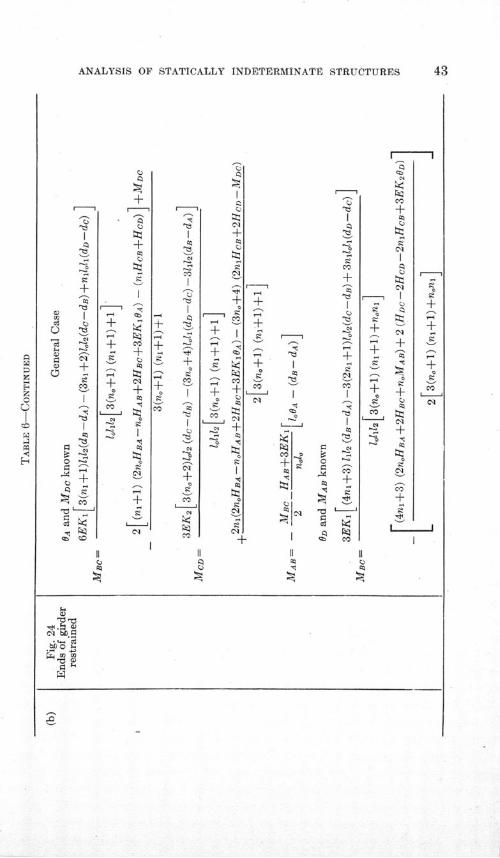
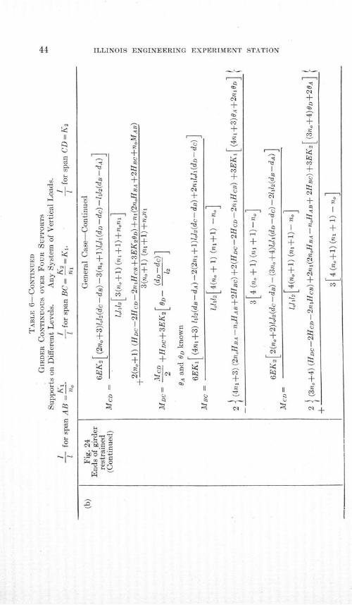
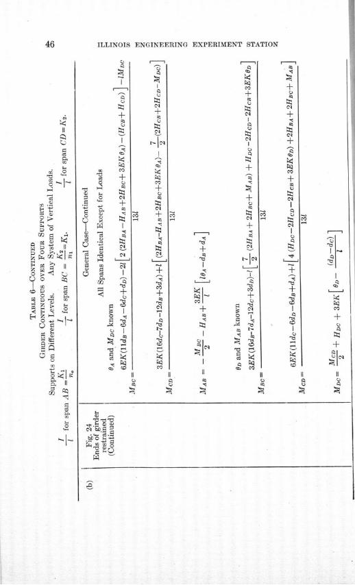
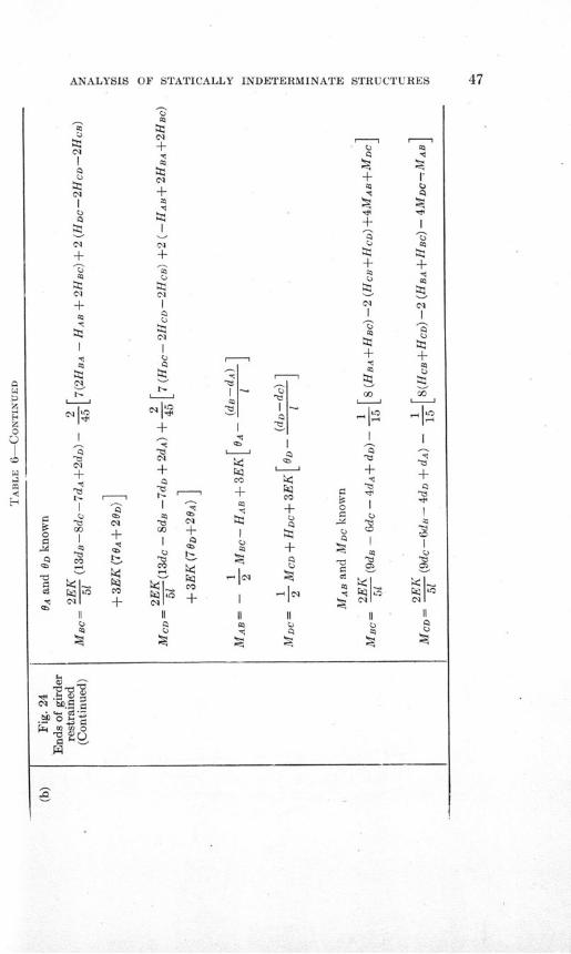
21. Girder Continuous over Four Supports and Carrying Any
System of Vertical Loads. Supports on Different Levels. Various Con-
ditions of Restraint of Ends.-Table 4, section 19, gives the general
equation of three moments which may be applied here. The method
of using the equation of three moments is to apply it successively to
each pair of adjacent spans in the continuous girder, thus deriving one
less equation than the number of spans. If the conditions of restraint
at the ends of the continuous girder are known, these equations may
be solved simultaneously for the unknown moment at each support.
When the end of the girder is hinged, the moment there is zero.
When the end is fixed, the slope there is zero. When the end is re-
strained, if either the slope or the moment at the end is known, the
moments at the other supports may be found.
The equations of Table 4 have been applied to the girder described
in this section, and the values of moments obtained for various cases
of restraint of ends are given in Table 6.
*Johnson, Bryan, and Turneaure, "The Theory and Practice of Modern Framed Structures,"
Part II, p. 19, Ninth Ed. 1911, give the general Equation of Three Moments for a continuous girder
with supports on different levels and carrying concentrated loads. The pocketbook, Die Huette, and
Lanza, Applied Mechanics, have similar equations.
A. Ostenfeld, Teknisk Statik, Vol. 2, Second Ed., Copenhagen, 1913, pp. 98-162, gives a com-
prehensive treatment of continuous girders, including the case of varying moment of inertia from
point to point, and of girder resting upon elastic supports. Both analytical and graphical methods
are presented.
ILLINOIS ENGINEERING EXPERIMENT STATION
TABLE 4
CONTINUOUS GIRDERS
Equations of Three Moments.
Supports on Different Levels.'
Any System of Vertical Loads.2
IK =T for right-hand span.K In -=Tfor left-hand span.
' If there is no settlement of supports, let all values of d in these equations equal zero.2 If therd are no loads on girder except at supports, let all values of H in these equations equal zero.
N Portion of Girder Equations of Three MomentsNo. Considered
(a) Fig. 16 nMAB+2MBc(n+1)+McD = [li(dB-dA) -
Intermediate spans (dc - dB) -2 [HB nHBA]
(b) Fig. 17 6EK d- JTwo adjacent spans 2M (+l)Mcd- -(dc-
at left-hand end. FEnd of girder hinged. -2 nHBA + HBcJ
(c) Fig. 18 16EK dd -_(dcd)Two adjacent spans nMAB+2MBC(n+ I) = 1 d.-d) - dc-dat right-hand end. F 1End of girder hinged. -2[?fHBA+HBC
(d) If MAB is known
2MBc(n+l)+McD = K li(dB-dA) -lo(dc-d) ]
Fig. 19 -2 [HBc + nHBA] -nMABTwo adjacent spans Lat left - hand end. If BA is knownEnd of girder re- 1strained. MBc(4+3n)+2MCD =6E_ l [31s(dB-dA) -21(dc-d)
+2nHAB-4 [ HBc+nHBA] -6EK OA
If the girder is fixed at A, OA = 0
(e) If MCB is known=6EK r 1
nMAB+2MBc(n+1) = - [li (dB-dA) -lo( dc-d)
Fig. 20 - 2 +MBTwo adjacent spansat right - hand end.End of girder re- If Oc is knownstrained. 6EK 1
2nMAB+MBc(4n+3) = 1-1 [ 2 1(d-dA)-31o (dc-dB)]
-4[HBc+nHBA] +2HcB+6EK Oc
If the girder is fixed at C, Oc = 0

ANALYSIS OF STATICALLY INDETERMINATE STRUCTURES
FIGURE 17
MA. <dA d dc c.4 8
-A
-1.
FIGURE 18
FIGURE 19
FIGURE 20
ILLINOIS ENGINEERING EXPERIMENT STATION
TABLE 5
GIRDER CONTINUOUS OVER THREE SUPPORTS
Supports on Different Levels.' K- =- for right-hand span.
Any System of Vertical Loads.2 -- = -for left-hand span.n I
(a) Fig. General Case21
6EK 2h+S MBc=21ol (n+ 1) li(d -d)-lo(dc- d) T+ F nHBA+Hac
Spans Identical Except for Loads
MBa= - l(2dB-dA-dc) - +HecC 211
General Case(b) Fig. OA and MCB known
22 MBC =3 4 1 31dd-dA) -21, (dc-dB) +2nH ,
- 4 (HBC +nHBA) -6EKOA + 2MB
M = 3EK( O dB-dA MBCMB-= II-----HAB
Oc and MAB known
.MBC= G K2l(d--dA)--31(dc-dB) -4(Hec+nHBA)Si4n+3
a + 2HcB +6EK9c- 2nMAB
M ac BCo da
2l
"• McB =M +3EK[C dc-d\+Hcn
7Z OA and Oc known
MBC = 1 6- K [i h (-dBA) - 1dc-d) nCBA-CBCnW +1 loT L
-2EK(OA-Oc)
MAB= 3EK [ A -d --d - MB--HAB
rc dc- d[CA- MBC, 2 AM = 3 EK ec dc-dB] +-2 +HCB
1 If there is no settlement of supports, let all values of d in these equations equal zero.
2 If there are no loads on girder except at supports, let all values of H and C in these equations
equal zero.
If an end is fixed, 0 for that end is zero.
If an end is hinged, M for that end is zero.
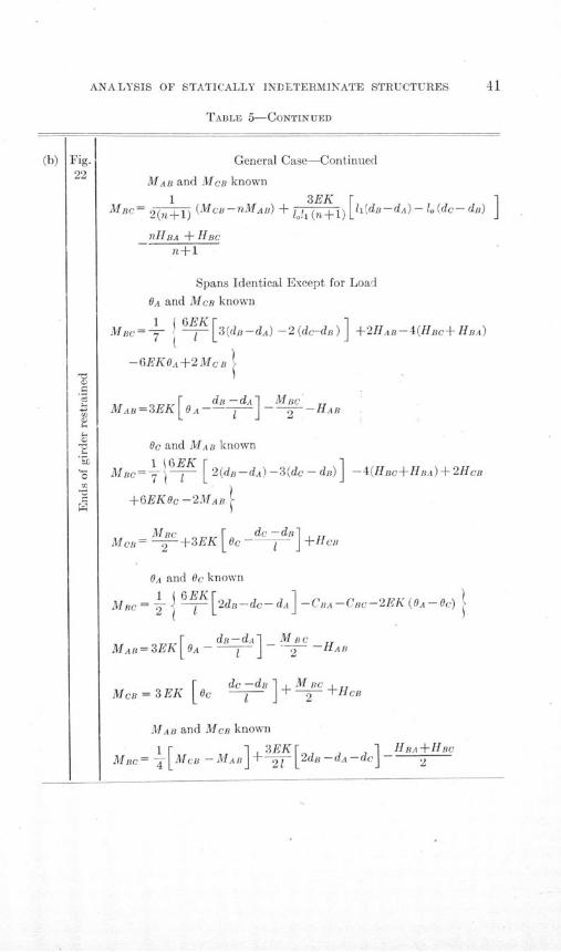
ANALYSIS OF STATICALLY INDELTERMINATE STRUCTURES 41
TABLE 5-CONTINUED
(b) Fig.22
'UC)
aC)
CL
'Ci
C
General Case-Continued
MAB and MCB known
1 3EK rMBc= 2(n+1) (MCB-nMAB) + o(1n+1)
l 1
d B - d A ) -1 o(dc- d) ]nHBA + HBC
n+1
Spans Identical Except for Load
OA and MeB known
MBC - EK [3(dB-dA) -2(dc-dB) +2HAB-4(HBc+ HBA)
-6EKOA+2McB -
MAB= 3 EK[ Ad 1d] 2 -M HAB
Oc and MAB known
MBc= ý 6 [2(dB-dA)-3(dc--d)] -4(HBC+HBA)+2HcB
+6EKOc -2MAB
McB M2+3EK c- d +HCn
OA and Oc known
MBC 6E•2dB-dc- dA -CiA -- Cc-2EK (OA-Oc) )
S dR-dA M_ cMAB=3EK[ OA ] t -HAB
MCB = 3EK [ o dc - d B + M 2 c +H e B
MAB and MCB known
MBc = -[Mc -MAB] + 2 2d- dA -d HA
(b)
42 ILLINOIS ENGINEERING EXPVRIMENT STATION
.4II
'4
V'4
42
p. ~
cI~E
II
~U) ~
~4) ~.U)
-~ V
42
4-.
'4
U)
'U0
4-.. V
::: tt3+ +
o2
10
___ ..S 4 -&
4 , p. 4
A 4) + + | (
I +? 1 '~ C-
^4 ̂ ?a
-4 I -' - 0
+ ts + i' - -, i.
* ^4 ±
U ' U -4Lt )+-' 6 o B i
- 'I I 4- l, &i
C11. bo
'3Z
42 ILI, INOIS ENGINEERING EXPERIMENT S•TION
4'
-4)
.4)
.4)
+-~ I-4)
I -~
42 ~ + ~'4 ~4) - ~ ~4)
- U
;: ± ~2
~+ ± 4-44) - U ~.) +0 ~ '~- Z~
L4
-4) ~.-U
c'14, - .4
LJ
0
0
6 Co
0
.0
C 4.00
1,514,04,t
- 44 .'*4,
2
4,s
S o4,444&.4.),3 4.04,
040.
044.
0 4
4. -4
00a^
a) V
4S- .4)4,§)544-U).0. 0-U.U4,
ANALYSIS OF STATICALLY INDETERMINATE STRUCTURES 43
r--- I
zpz
A
alE-
S 1 -4- I '5 I
+
±
±
I - ~
a~ ± Co- +
Cl+ -~
+Co ~
~ LJ
~ -~ I
+
II II II II. C)
.^ .h lC)Se
Cl 1
-^ 8
tCl
+ +
CID
CCD
+ +
r4 cq
+ 4. t 5 a
*^ - §I -,
4 . C) CC o . - S +4 -7: '
5 ~ Co ^ '' I
Cl -l '
+4 ? 1
+C)
c~l
c~l
I
9t!+
t +
- + •
cli
Co
+
9?_._ 1-1Sq
9!^
44 ILLINOIS ENGINEERING EXPERIMENT STATION
cq
C1CCO
+;
~i 0
~
~i2~
0 ~Z r~4 ~
Z r~ ~ II0 ~11 ~
~
0-~
E-4Z0 -~ ~ -~
0
*
+-~I ~II II (2(2 (2
(2 (2Cl
Cl±(2
+(2
CO
cliI
'E3(2
- (
+ f,
-+ I
C11
C11
S+(2i
a |
z
CO
±4-Prý
+ e°co•
+ +(2
"I
r Cl
'+ ) I-S
t t!
(2°Cl.
(2?(2T l
Cl+ i-
(23(2'
(2(2 -N--
Cl~
0-")-i
0;
CO
(1 1
(-2
(20 O
+-"C3
-CA
+l +
+
+ P+4
+ -- C !
11 +B C11 +? -
-cI
^- I^
r1 +
+ C C4I Kl +, ~
= (2 + o
I (2 -Z
(2 L "^ 21l | S | ___ 1
t+ I _ (C2
4- § C l
^ ^'^ l °3.O
0
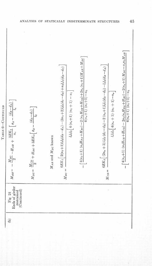
ANALYSIS OF STATICALLY INDETERMINATE STRUCTURES 45
z
0
H
II II II It
^__ ~ i+
S+ +_, „-"n - -+
qe'
- -S S'-i +
IO -s i '- ' e + °'-+ 0§ cC+--.
t.I ^ ' I -
+-- I ~ 01 + 01S*-~ ~ L.8) -- "
C.)0
01
F-
N
+0A
LJ 0
+
0
C.)s
0 ^
0 ^
46 ILLINOIS ENGINEERING EXPERIMENT STATION
0Cd0
,z 0 C
L 0§
0
00 s
HZ
02-.003CO0
0,B
0 S I
00&
§ V
±
-F
0 I
Q
z 0 CIA
S+0 o
ti!
0+
m 01
0 0 L
-g ^
*S 0 (N.0 cO
1 0
01
+
Cl
+
CA0
01
+
01
I1
I
L
CO
+
I
§01
0
+
- -0-
+
to
+ 0 *
0 |
13 t,.I
^ I1
CQ+
to0
:lz01
+01
+0.
+
I
01
c--
01
-tiI
(N
I» 0
co t
0e
I II - I II I
I
÷
+0
+
~II"
3- 0.-, ,L 0Q
44 Sg
4{} ILLINOIS ENGINEERING EXPERIMENT STATIONr I r ---- n I
ANALYSIS OF STATICALLY INDETERMINATE STRUCTURES 47
C3
C) I- r,~cl + C)
+++
+ +
++C)q
+ + c*< --I -- !
II II+
<)
Cl~
+ I <
I II e
cli
Co --- t
cl cq cS cB
I ~ -&
Co --^
I I -> I
bo +
I- +& ' - + 4I
Co ~:- s - C)
1 ?
Io T c
ili
1 II II 11 II II 1IC) C) C)§§
^ ^ ^ ^ C
a) 0
18 ILI INOIS ENGINEERING EXPERIMENT STATION
FiGlRE 21
FIGURE 22
FIGURE 23
FIGURE 24
ANALYSIS OF STATICALLY INDETERMINATE STRUCTURES
VI. TWO-LEGGED RECTANGULAR BENT. LEGS OF EQUAL LENGTH
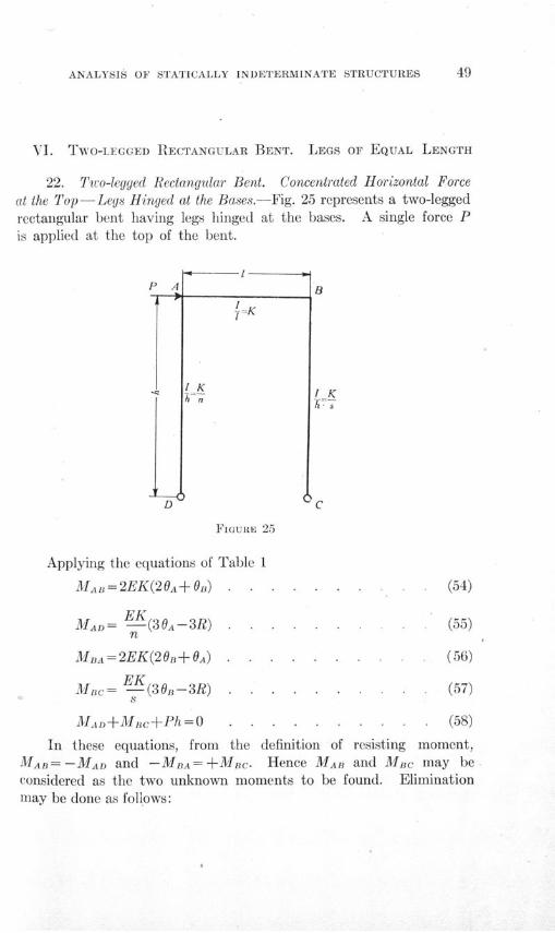
22. Two-legged Rectangular Bent. Concentrated Horizontal Forceat the Top-Legs Hinged at the Bases.-Fig. 25 represents a two-leggedrectangular bent having legs hinged at the bases. A single force Pis applied at the top of the bent.
B
I K
Applying the equations of Table 1
MAB=2EK(20A+OB) • .
MAD= -(30A-3R) .n
Ma1A=2EK(206B+0A)
EKMc= EK(30,-3R) .
8
MAD+ MBc+Ph=O
(55)
(56)
(57)
(58)
In these equations, from the definition of resisting moment,MA= -MAD and -MBA=+Mc. Hence MAB and MBc may be
considered as the two unknown moments to be found. Eliminationmay be done as follows:
FIGURE 25
ILLINOIS ENGINEERING EXPERIMENT STATION
Subtracting equation 56 from equation 54 gives
MAB+MBc=2EK(6A- B) . . . . . . . . (59)
Subtracting s times equation 57 from n times equation 55 gives
-nMAB-sMBc= EK(30A-3GB) . . . . . . (60)
Combining equations 59 and 60 to eliminate the quantity (0A- OB)
givesMAB(3+2n)+MBc(3-ý2s)=0 . . . . (61)
Combining equation 61 with equation 58 gives
Ph( 3+2sMAB= 2T 3+n0 ) . . . .. . .. . . (62)
- Phi 3+2n . . ..... (63)M n=-- (63)
If n = s, that is, if the sections of AD and BC have the same momentsof inertia, equations 62 and 63 take the form
Ph (64)Mac= -MAB (64).......
A B/
IK
SK I Kh
C
FIGURE 26
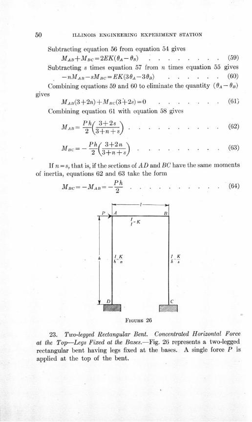
23. Two-legged Rectangular Bent. Concentrated Horizontal Force
at the Top-Legs Fixed at the Bases.-Fig. 26 represents a two-leggedrectangular bent having legs fixed at the bases. A single force P is
applied at the top of the bent.
D
ANALYSIS OF STATICALLY INDETERMINATE STRUCTURES 51
Applying equation (A), Table 1,
.MAB=2EK(20A+0B) . . . . . . . . . (65)
MAD=-- (20A-3R) . . . . . . . . (66)n
MDA= (A - 3R) . . . . . . . . . . (67)
MA =2EK(20B+OA) . . . . . . . . . . (68)
MBc= 2EK (20 B-3R) . . . . . . . . . . (69)
M = 2E- (O-3R) . . . . . . . . . . (70)
MAD+MDA+MBC+MCB+Ph=0 . . . . . . (71)
MAB+MAD=O .. .. . . . . ... . (72)
MA+MBC=O .=0 ..... .... . (73)
Substituting the values of MAB and MAD from equations 65 and 66in equation 72 and simplifying gives
S(1+ n)+ =3 . . . . . . . . . . (74)
Substituting the values of MBA and Mac from equations 68 and 69in equation 73 and simplifying gives
2-B(1+s)+ =3. ... . . .... . (75)
Substituting the values for the moments in equation 71 and sim-plifying gives
-OA =2(s+n) . . (76)-R.-- R 6EK R.....
Solving equation 74 for -- gives
OB 3 20Auln\ (77~ n n ) . . . . . . . .* . (77)R n Rk.n
Substituting the value of from equation 77 in equation 75 gives
OA 3(2s+2-n)-R 3ns+4n+4s+4 ...... (78)
ILLINOIS ENGINEERING EXPERIMENT STATION
6ASubstituting the value of - from equation 78 in equation 77 and
simplifying gives
OR 3(2n+2-s) (79)R 3ns+4n+4s+4 ......
OA BSubstituting the values of -7- and - from equation 78 and equa-
tion 79 in equation 76 gives
3s(2s+2-n) 3n(2n+2-s) ns Ph 13ns+4n+4s+4 3ns+4n+4s +4 6EK R
Solving this equation for - gives
1 6EK 2(3ns2 llns+s 2+s+3n 2s+n 2+n)R ns Ph 3ns+4n+4s+4 (80)
Substituting the value of - from equation 80 in equation 79 and
solving for OB gives
Ph 3ns(2n+2-s)B 12EK 3ns2+llns+s2+s+3n?2s+n+n (81)
1
Substituting the value of - from equation 80 in equation 78 and
solving for OA gives
Ph 3ns(2s+2-n)A 12EK 3ns2+llns+s2+s+3n2s+n 2+n
Substituting the values of 0n and OA from equations 81 and 82in equation 65 gives
M =Ph 3ns(s+2)2 3ns2+ llns+s2+s+3n
28 +n 2+n (83)
Substituting the values of 0B and OA from equations 81 and 82in equation 68 and substituting -Mac for MBAAgives
Ph 3ns(n+2) (84)BMD- 2 3ns2+llns+ s2+s+3n2s+n 2 n
ANALYSIS OF STATICALLY INDETERMINATE STRUCTURES
From equation 67
MDA-2EKR [ A-3] . ....... (85)
Substituting the value of R from equation 80 and of -fromR
equation 78 gives
Ph s(2s+2+5n+3ns)2 3ns2 +llns+s2+s+3n 2s+n 2 +n (86)
From equation 70
MCB= 2EKR(0 - 3
Substituting the value of R from equation 80 and of -- from
equation 79 gives
MCB=- Ph n(2n+2+5s+3ns) (87)2 (3ns2+llns+s2+s+3n2 s+n 2+n)
Letting Ao represent 2(3ns2+llnss 2+s+3n2s+n 2 +n), the equa-tion for the moments in the frame are
MAD =- P 3ns(s+2) . . . . . . . . . (88)
PhMBc = - P3ns(n+2) . . . . . . . . . (89)
PhMCB = - Phn(2 n+ 2 +5s+ 3 ns) . . . . . . . (90)
MDA = -- s( 2s+2+ 5 n+3ns) . . . . . . . (91)
If n= s, that is, if the section of AD has the same moment ofinertia as the section of BC, equations 88 to 91 take the form
Ph 3nMAD=MBC- 2 . . . . . .. . (92)
Mc =MA . .Ph 3n+1 (93)2 6n+1......
ILLINOIS ENGINEERING EXPERIMENT STATION
If n= s= 1, equations 92 and 93 take the form
MAD=Ms= -3 Ph ........ .
14
McB=MDA= - Ph
(94)
(95)
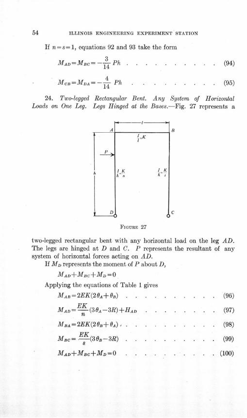
24. Two-legged Rectangular Bent. Any System of HorizontalLoads on One Leg. Legs Hinged at the Bases.-Fig. 27 represents a
P
D
FIGURE 27
two-legged rectangular bent with any horizontal load on the leg AD.The legs are hinged at D and C. P represents the resultant of anysystem of horizontal forces acting on AD.
If MD represents the moment of P about D,
MAD+MBC+MD= 0
Applying the equations of Table 1 gives
MAB=2EK(20A+OB) . . . . . . . . . . (96)
EKMAD = -(3eA-3R)+HAD . . . . . . .
li1
MBA =2EK(20B+ OA) .
EKMac= .-- (30B-3R) .
MAD+MBC+MD=O . .( . (100)
ANALYSIS OF STATICALLY INDETERMINATE STRUCTURES
Equations 96 to 100 are almost identical in form to equations 54to 58 of section 22. Hence the solution for the moments by eliminatingvalues of 6 and R, as in section 22, gives
1 MD(2s+3)-2n HADMA = - n+s+3 . . . . . . . (101)
1 MD(2n+3)+2n HAD (102)MBC = - nIs -......... . .. (102)
2 n+s+3
If n = s, that is, if the sections of AD and BC have the same momentsof inertia, equations 102 and 101 take the form
MBC= - M.+ ] ....... (103)2 2n+3
MA--[M- n' ] . . . . . . . (104)
If n= s= 1, equations 103 and 104 take the form
MBC= - [5MD+2HAD] . . . . . . . . (105)
MA= [5MD-2HAD .. . . . . . . (106)
If both legs of the bent are loaded and if the bent and loads aresymmetrical about a vertical center line
MAB= MBC-[ 2 n ]HAD .. . . . . . . (107)
Values of HAD to be used in equations 101 to 107 are given inTable 2.
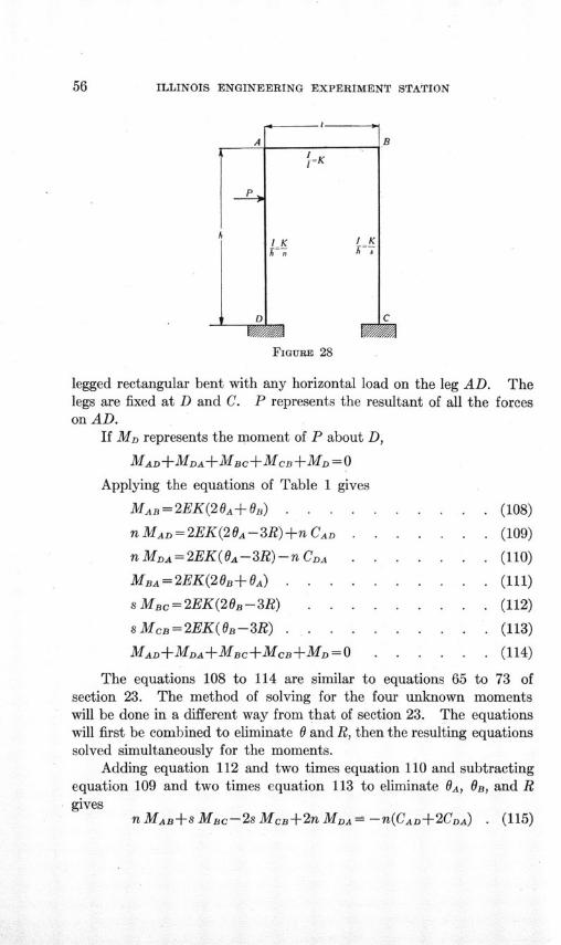
25. Two-legged Rectangular Bent. Any System of HorizontalLoads on One Leg-Legs Fixed at the Bases.-Fig. 28 represents a two-
ILLINOIS ENGINEERING EXPERIMENT STATION
A
D
I K I Kh~n *
B
C
FIGURE 28
legged rectangular bent with any horizontal load on the leg AD. Thelegs are fixed at D and C. P represents the resultant of all the forceson AD.
If MD represents the moment of P about D,
MAD+MDA+MBC+MCB+MD = 0
Applying the equations of Table 1 gives
MARB=2EK(20A+OB) . . . .. . . . . (108)
n MAD= 2EK(2OA -3R) +n CAD . . . . . . . (109)
nMDA=2EK(0A-3R)-nCDA .. ... . . . (110)
MBA=2EK(20B+ OA) . . . .. . . . . . (111)
sMBc=2EK(20B-3R) . . . . . . . . . (112)
s McB=2EK(0B-3R) ... .. . . . . . (113)
MAD+MDA+MBC+MCB+MD=O .. . . . . (114)
The equations 108 to 114 are similar to equations 65 to 73 ofsection 23. The method of solving for the four unknown momentswill be done in a different way from that of section 23. The equationswill first be combined to eliminate 0 and R, then the resulting equationssolved simultaneously for the moments.
Adding equation 112 and two times equation 110 and subtractingequation 109 and two times equation 113 to eliminate 0
A, 6B, and Rgives
n MAB+s MBc-2s McB+2n MDA= -n(CAD+2CDA) . (115)
•JfJ•
ANALYSIS OF STATICALLY INDETERMINATE STRUCTURES 57
Adding equation 109 and two times equation 112 and subtractingequations 110 and 111 and two times equation 113 gives
-nMAB+(2s+1)MBc-2sMcB-nMDA =n(CAD+CDA) (116)
Adding equations 108, 110 and 112, and subtracting equations109, 111 and 113 gives
(n+1)MAB+s+ 1)MBc-s Mc+n MDA=
-n(CAD+CiA) . . . . . . . . . . (117)
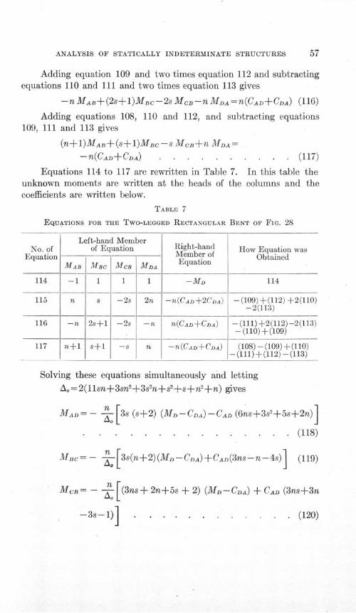
Equations 114 to 117 are rewritten in Table 7. In this table theunknown moments are written at the heads of the columns and thecoefficients are written below.
TABLE 7
EQUATIONS FOR THE TWO-LEGGED RECTANGULAR BENT OF FIG. 28
Left-hand Memberof Equation
MBC
1
2s+l1
s+1
MCB MDA
1 1
-2s
-2s
-s-
2n
-n
n
Right-handMember ofEquation
-MD
-n(CAD+2CDA)
n(CAD+CDA)
-nT(CAD+CDA)
How Equation wasObtained
114
-(109)+(112) +2(110)-2(113)
-(111) +2(112)-2(113)- (110) +(109)
(108) -(109) +(110)-(111)+(112) -(113)
Solving these equations simultaneously and lettingAo= 2(11sn+3sn2+3sn+s2+s+n2 +n) gives
MAD= - - [3s (s+2) (MD-CDA) -CAD (6ns+3s2+5s+2n)J
.. . . . . . . . . . . .. .. (118)
Mnc=- [3s(n+2)(M - C DA) +CAD(3ns-n-4s) ] (119)
MCB= - -- (3ns+ 2n+5s + 2) (MD- CDA) + CAD (3ns+3n
-3s-1) . . . . . . . . . . . . (120)
No. ofEquation
114
115
116
117
MAB
-1
n
-n
n+1
58 ILLINOIS ENGINEERING EXPERIMENT STATION
MDA = - s (3ns + 2s + 5n + 2) (MD- CDA)
+ n CAD(3s2+12s+1) ]-CDA . . . ... . (121)
If n=s equations 118 and 121 take the form
n 3(MD - CDA) 1CAD 3 (122)M D--2 6n+1 n 2 6n )
M - n 3(MD-CDA) +CD 1 32 6n+1 (nA+2 6 1 (123)
M 1 (3n+1) (MD-CDA) 1 3n ]MCB- - 6n+1 CAD- n+2 6n+1)
. . . . . . . . . . . . . . . . . (124)
1 [(3n+l) (MD-CDA) 1 3nMDA =- ---2 6n+1 +CAD(-+2 6n+1)l
- CDA . . . . . . . .. . . . (125)
If both legs of the bent are loaded and if the bent and loads aresymmetrical about a vertical center line
MAB=MBC=- n CAD . . . . . . . . (126)n+2
1MCB= -MDA= -- CAD +CDA . . . . . . (127)
n+2
Values of CAD and CDA to be used in equations 118 to 127 are given
in Table 2.
26. Two-legged Rectangular Bent. Any System of Vertical Loadson the Top-Legs Hinged at the Bases.-Fig. 29 represents a two-leggedrectangular bent having any system of vertical loads on AB. Thelegs are hinged at D and C. P represents the resultant of the loadson AB.
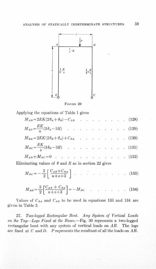
ANALYSIS OF STATICALLY INDETERMINATE STRUCTURES
D
1P
I-
FIGURE 29
Applying the equations of Table 1 gives
MAB=2EK(20A+OB)-CAB . . . . . . . . (128)
EKMAD=-EK(30A-3R) . .. . . . . . . (129)
n
MBA=2EK(20B+OA)+CBA . . . . . . (130)
EKMBc=-EK(30OB-3R) . .. . . . . . . (131)
8
MAD+MBC=O ... . . . . . . . . (132)
Eliminating values of 0 and R as in section 22 gives
3 [CAB + CBA
MAD= ns3 - MBC * * . (134)
Values of CBA and CAB to be used in equations 133 and 134 aregiven in Table 2.
27. Two-legged Rectangular Bent. Any System of Vertical Loadson the Top-Legs Fixed at the Bases.-Fig. 30 represents a two-leggedrectangular bent with any system of vertical loads on AB. The legsare fixed at C and D. P represents the resultant of all the loads on AB.
t
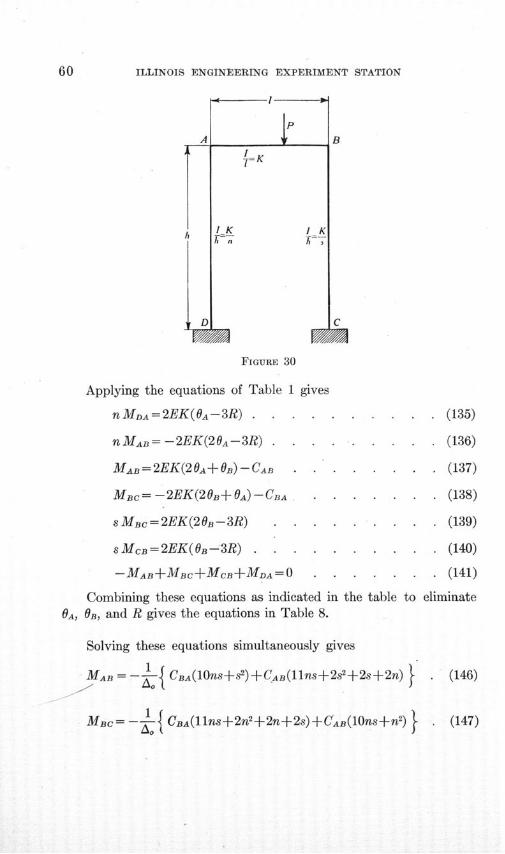
ILLINOIS ENGINEERING EXPERIMENT STATION
1= K
IKA~n
I KAT
FIGURE 30
Applying the equations of Table 1 gives
nMDA=2EK(OA-3R) . ... . . . . . . . (135)
nMAB= -2EK(2OA-3R) . . . . . . .... . (136)
MAB=2EK(20A+OB)-CAB . . . . . . (137)
MBc= -2EK(20B+ OA)-CBA . . . ... . . (138)
sMBc=2EK(20B-3R) . . . . . . . . (139)
sMcB=2EK(OB-3R) . . . . . . . . . . (140)
-MAB+MBC+MCB+MDA=O . . . . . . . (141)
Combining these equations as indicated in the table to eliminateOA, OB, and R gives the equations in Table 8.
Solving these equations simultaneously gives
MAB -- CBA(O10ns+s2)CAB(llns+22+2s+2n) } (146)
MBc=-- { CBA(llns+2n2+2n+2s)+CAB(10ns+n2) . (147)
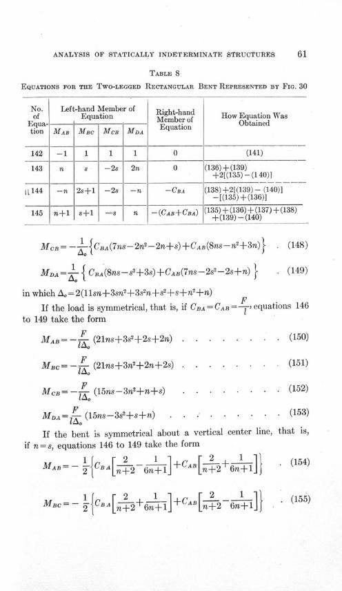
ANALYSIS OF STATICALLY INDETERMINATE STRUCTURES 61
TABLE 8
EQUATIONS FOR THE TWO-LEGGED RECTANGULAR BENT REPRESENTED BY FIG. 30
Left-hand Member ofEquation
MBC
1
2s+1
s+1
MCB
1
-2s
-2s
-8
MDA
1
2n
-n
n
Right-handMember ofEquation
0
0
-CBA
-(CAB+CBA)
How Equation WasObtained
(141)
(136)+(139)+2[(135) -(140)]
(138)+2[(139) - (140)]-[(135)+(136)]
(135) + (136) + (137) + (138)+(139) -(140)
McB= 1- CBA(7ns-2n2-2n+s))+CAB(8ns--n+3n) . (148)
MDA =-- {CBA(8ns- s2+3s)+CAB(7ns- 2s- 2s+n) . (149)
in which Ao= 2(11sn+3sn2+3s2n+sI+s+n 2+n)
If the load is symmetrical, that is, if CBA = CAB -,equations 146
to 149 take the form
MAB=-- (21ns+3s2+2s+2n) . . . . . . . . (150)
MBc= -F (21ns+3in+2n+2s) . . . . . . . . (151)
MCB= -F (15ns-3n2+n+s) . . . . . . . . (152)
MDA = F (15ns-3s2+s+n) . . . . . . . .. (153)i .
If the bent is symmetrical about a vertical center line, that is,
if n = s, equations 146 to 149 take the form
MAB= - {CBA[2 _1 ]+CAB 2. (154)
MBc= - CBA n-+6 1 +CAB - 2 6nl (155)
No.of
Equa-tion
142
143
iL14 4
145
MAB
-1
n
-n
n+1
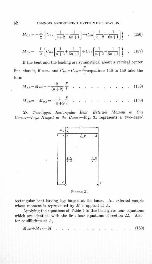
ILLINOIS ENGINEERING EXPERIMENT STATION
1 1 1 1 1Mec =--L CBA 1 - l+CAB - 2+ 6 1 . (156)
MDA-= -- { [ 1 + 1 ] +6 -1] . (157)
If the bent and the loading are symmetrical about a vertical center
Fline, that is, if n= s and CBA = CAB =-, equations 146 to 149 take the
form
MAB=MBc-= 2 F (158)(n+ 2) 1
1FMCB =-MDA ....... (159)n-+2 1 . . . . . . . . .
28. Two-legged Rectangular Bent. External Moment at OneCorner-Legs Hinged at the Bases.-Fig. 31 represents a two-legged
D
A IK B
K I K
i t
C
FIGURE 31
rectangular bent having legs hinged at the bases. An external couplewhose moment is represented by M is applied at A.
Applying the equations of Table 1 to this bent gives four equationswhich are identical with the first four equations of section 22. Also,for equilibrium at A,
C
. (160)MAD +MAB= M
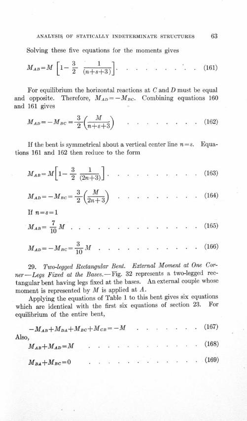
ANALYSIS OF STATICALLY INDETERMINATE STRUCTURES
Solving these five equations for the moments gives
MAB=M [- (n -3)] .. . . .. ...* (161)
For equilibrium the horizontal reactions at C and D must be equaland opposite. Therefore, MAD =- MB Combining equations 160and 161 gives
MAD= -MB = ( ) . . . . . . . . (162)
If the bent is symmetrical about a vertical center line n = s. Equa-tions 161 and 162 then reduce to the form
101MA=M i 3 - )]-j 3 12 (163)
MAD-MB=3( M . . .. . . . . . (164)
If n=s=l1
MAB= 7M . . . . ......... . (165)
MA = -Mc =- M . . . . . . . . . . . (166)
29. Two-legged Rectangular Bent. External Moment at One Cor-
ner-Legs Fixed at the Bases.-Fig. 32 represents a two-legged rec-
tangular bent having legs fixed at the bases. An external couple whose
moment is represented by M is applied at A.
Applying the equations of Table 1 to this bent gives six equations
which are identical with the first six equations of section 23. For
equilibrium of the entire bent,
-MAB+MDA+MBC+MCB = -M . . . . . . . (167)
Also,
MAB+MADM=M . . . . . . ..... . (168)
. (169)MBA +MBc= 0
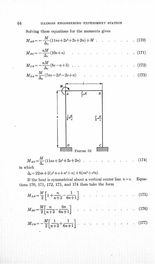
ILLINOIS ENGINEERING EXPERIMENT STATION
Solving these equations for the moments gives
MAB= -- (11ns+2s2+2s+2n) +M . . . .
MBc=-c - (10s+n) . . . . .
Mc= (8s-n+3) . . . . . . . .
MMDA=-(7ns-2s2-2s+n) . . . . . .MA =
. . (170)
. (171)
. (172)
. (173)
(174)MAD -(llns+2s2+2s-+ 2 n) .
in which
A o = 22sn+2(s2+s+n2±+n)+6(sn2+s 2n)
If the bent is symmetrical about a vertical center line n = s. Equa-tions 170, 171, 172, 173, and 174 then take the form
MAB = 1 + n. . ......... (175)2ý [ n+2 6n+1 ....l
M[ n 6nM B C
=2T n+2 6n+l . . .
Me=Ml 1 M 1 +12- ?T+2 6n+1-
S(176)
. (177)
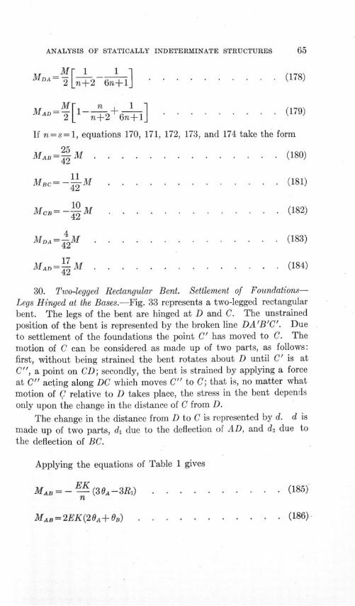
ANALYSIS OF STATICALLY INDETERMINATE STRUCTURES
M 1 1MDAM [ I= I . . . . .......... (178)
Mr1 n 1 (179)MAD = [l--+2 6n+1J . . . . .(179)
If n=s=1, equations 170, 171, 172, 173, and 174 take the form
MAB = 2•-M . ........ ..... (180)42
Mac= - 1M . . . . . . . .. . . . . (181)
42
17MAD = - (183)
Ma4D ="• M ... ......... . (184)
30. Two-legged Rectangular Bent. Settlement of Foundations-Legs Hinged at the Bases.-Fig. 33 represents a two-legged rectangularbent. The legs of the bent are hinged at D and C. The unstrainedposition of the bent is represented by the broken line DA'B'C'. Dueto settlement of the foundations the point C' has moved to C. Themotion of C can be considered as made up of two parts, as follows:first, without being strained the bent rotates about D until C' is atC", a point on CD; secondly, the bent is strained by applying a forceat C" acting along DC which moves C" to C; that is, no matter whatmotion of C relative to D takes place, the stress in the bent dependsonly upon the change in the distance of C from D.
The change in the distance from D to C is represented by d. d ismade up of two parts, di due to the deflection of AD, and d2 due tothe deflection of BC.
Applying the equations of Table 1 gives
MA= --EK (30A-3Ri) . . . . . . . . . . (185)n
MAB= 2EK(2 0 + B) . (186)
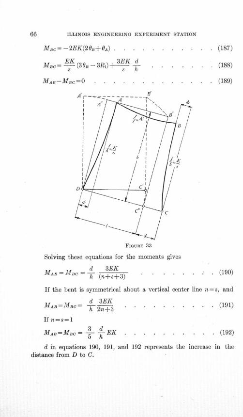
ILLINOIS ENGINEERING EXPERIMENT STATION
Mac= -2EK(20BO+A) . . . . . . .. . . . . (187)
Mc= EK(30B-3R1 )+ 3E K d (188)
MAB-MBc=O . . . .. . . . . . . . (189)
FIGURE 33
Solving these equations for the moments gives
MAB = MBC = d 3EKMAB Bc = (ns+3).... (190)h (n+s+3)
If the bent is symmetrical about a vertical center line n= s, and
d 3EKMAB=MBC= d +3 . . . . . .. . . . (191)
h 2n+3
If n=s=13d
MAB =MBC = 3- -EK ....... ... . (192)5 h
d in equations 190, 191, and 192 represents the increase in thedistance from D to C.
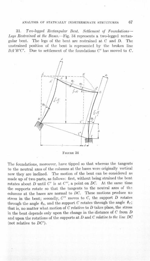
ANALYSIS OF STATICALLY INDETERMINATE STRUCTURES
31. Two-legged Rectangular Bent. Settlement of Foundations-Legs Restrained at the Bases.-Fig. 34 represents a two-legged rectan-gular bent. The legs of the bent are restrained at C and D. Theunstrained position of the bent is represented by the broken lineDA'B'C'. Due to settlement of the foundations C' has moved to C.
FIGURE 34
The foundations, moreover, have tipped so that whereas the tangents
to the neutral axes of the columns at the bases were originally verticalnow they are inclined. The motion of the bent can be considered as
made up of two parts, as follows: first, without being strained the bent
rotates about D until C' is at C", a point on DC. At the same time
the supports rotate so that the tangents to the neutral axes of the
columns at the bases are normal to DC. These motions produce no
stress in the bent; secondly, C" moves to C, the support D rotates
through the angle OD, and the support C rotates through the angle Oc;that is, no matter what motion of C relative to D takes place, the stress
in the bent depends only upon the change in the distance of C from D
and upon the rotations of the supports at D and C relative to the line DC
(not relative to DC').
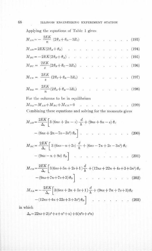
ILLINOIS ENGINEERING EXPERIMENT STATION
Applying the equations of Table 1 gives
2EKMA,,=- 2 K (20A+,-3R1) . . . . . . . . (193)
MAB=2EK(20A+ B) . . . . . .. . . . . . (194)
Mnc= -2EK(20B+0A) . . . . . . . . . . . (195)
2EKMBc = (20B±+Oc-3R) .... .... (196)
Mco = (20c+0B-3R2 ) ... ..... (197)
2EKMDA = - (20n+ A-3R1) . . . . . . (198)
n
For the columns to be in equilibrium
MDA-MAB+MBC+MCB= 0 . . . . ... .. (199)
Combining these equations and solving for the moments gives
MAB =2EK [3 (6ns + 2n - s) d + (9ns + 8n - s) Oc
- (6ns+2n-7s-3s2) D .. . . . . . .. (200)
Mac= 2E 3 (6ns-n+2s) d + (6ns - 7n + 2s - 3n 2) 0c
- (9ns - n + 8s) OD] . . . . .... . (201)
McB= [3(6ns+5n + 2s+ l) + (12ns+ 22n +4s+3+3n2)Oc
- (9ns+7n+7s+3) On . . . . . . . . . (202)
2EK 5 dMDA= - [ 3 (6ns + 2 n + 5s+) + (9ns + 7n + 7s+3)O0c
-(12ns+4n+22s+3+3s2) On . . . . . . . (203)
in which
Ao = 22ns+2(s2+s+ n 2 +n)+ 6(n 2s+s 2n)
ANALYSIS OF STATICALLY INDETERMINATE STRUCTURES
If the bent is symmetrical about a vertical center lihe n = s. Equa-tions 200, 201, 202, and 203 then take the form
MAB=EK d 3 Oc- OD . . . . (204)
Mc=OEKD + - 3(c+D . . . . (205)= h n2 n+2 6n+1
MCB= EK d 3(n+1) + 2n+3 D) 3(c ) (206)
h n(n+2) n(n+2) 6n+1
Sd 3(n+1) + 2n+3 (3(Oc+D) (207)
MA=-EKLh n(n+ 2 ) n(n+2) 6n+ 1 J
If n=s=l
MAB = [21 +160+20D] . . . . . . . . (208)
MB K= 214 -200-160] . . . . . . . . (209)
McB= EK[42 +440c-26D] . . . . . . . . (210)
MD= -_ [42- +260c-440D] . . . . . . . (211)
In all these equations' 0 is measured from a line normal to the
line CD.
If the foundations settle without tipping it is more convenient to
measure 0 from a line normal to the original position DC'. It is then
necessary to consider the vertical settlement d3.
Proceeding as before, if the tangents to the neutral axes of the
columns at their bases remain vertical, if the bases are separated
ILLINOIS ENGINEERING EXPERIMENT STATION
horizontally by an amount represented by d, and if C settles verticallyby an amount represented by d3, it can be proved that
MAB= 2EK[3 (6ns+ 2n-s) - 3(ns+2n+2s+s2 )_ d. (212)
MBC =2K [3 (6ns-n+ 2s) d + 3(ns+2n+2s+s2) ý . (213)
McB=j2 [3(6ns+5n+2s +l) d-- 3(ns+5n-s+n2) ] . (214)
MDA= - o 3 (6ns+ 2n+5s+ 1) + 3 (ns-n+5s+s2) ] (215)
If the bent is symmetrical about a vertical center line, n = s. Equa-tions 212, 213, 214, and 215 then reduce to the form
M•=E[dAl 3 d 6 * (216)MAB-EK[ -n21 6+ . . . . . . . . (216)
h n+2 1l 6n+1 . .......
M6c=1EK " " . . . . . .. (217)
MC=EK[ d 3(n+1) da 6 (218)
h n(n+2) 1 6n+1l
[ d 3(n+1) d 6
M,- EK _ ! . . . . . . (219)M --K h n(n+2) 1 6n+1 ......
If n=s=l[d 6 d3
MAB =EK h ... . . . . . . . (220)
Mac= EK[- + • •+1.... ........ (221)MC=EK[ d + 6 d3 . . . . (221)
h EK .........
M[2d 6 d31
MDA=- K[ + - .E• - . . . . . . .. . (223)h 7 1
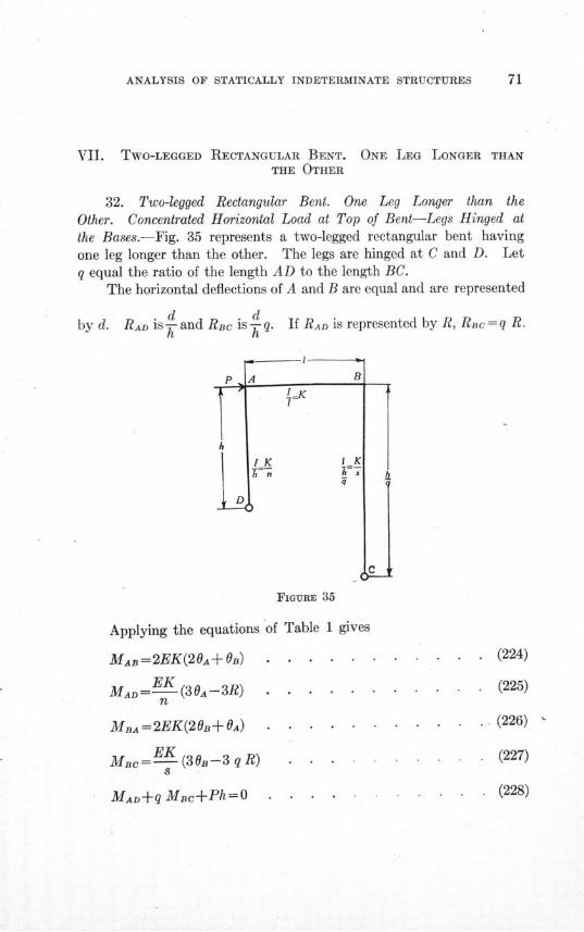
ANALYSIS OF STATICALLY INDETERMINATE STRUCTURES
VII. TWO-LEGGED RECTANGULAR BENT. ONE LEG LONGER THANTHE OTHER
32. Two-legged Rectangular Bent. One Leg Longer than theOther. Concentrated Horizontal Load at Top of Bent-Legs Hinged atthe Bases.-Fig. 35 represents a two-legged rectangular bent havingone leg longer than the other. The legs are hinged at C and D. Letq equal the ratio of the length AD to the length BC.
The horizontal deflections of A and B are equal and are represented
d dby d. RAD is T and Rac is k-q. If RAD is represented by R, RBcc=q R.
FIGURE 35
Applying the equations of Table 1 gives
MAs=2EK(20A+OB) . . . . . .
MAD= (3 0A-- 3 R) . . . . . .n
MBA=2EK(20B+OA) . . . . .
Mac=- (30-3 q R) . . .
MAD+q MBc+Ph=O . . . .
. (224)
. (225)
. (226)
(227)
(228)
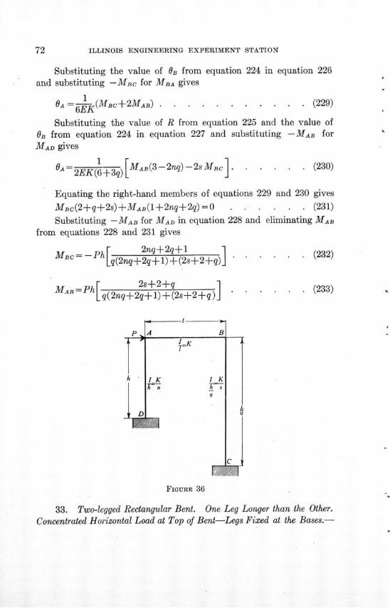
ILLINOIS ENGINEERING EXPERIMENT STATION
Substituting the value of OB from equation 224 in equation 226and substituting -Mac for MBA gives
1OA =--K(MBc+2MAB) . . . . . . . . . . . (229)
Substituting the value of R from equation 225 and the value of0B from equation 224 in equation 227 and substituting -MAB for
MAD gives
OA = 2 EK )[MAB(3-2nq) -2sMBc ]2EK(6+-3q)II
. (230)
Equating the right-hand members of equations 229 and 230 gives
MBc(2+q+2s)+MAB(1+2nq+2q)=0 . . . . .. (231)
Substituting -MAB for MAD in equation 228 and eliminating MAB
from equations 228 and 231 gives
M - Ph 2nq+2q+l[ q(2nq+2q+1) + (2s+2+q)
MAB =Ph[ 2s+2+qMA [q( 2nq+2q+ 1)+ (2s_+2+q)
(232)
(233)
FIGURE 36
33. Two-legged Rectangular Bent. One Leg Longer than the Other.Concentrated Horizontal Load at Top of Bent-Legs Fixed at the Bases.-
ANALYSIS OF STATICALLY INDETERMINATE STRUCTURES 73
Fig. 36 represents a two-legged rectangular bent having one leg longerthan the other. The legs are fixed at C and D.
The horizontal deflections of A and B are equal and are represented
. d dby d. RAD is W- and RBc is - q. If RAD is represented by R, RBc = qR
Applying the equations of Table 1 gives
MAB= 2EK(20A+OB) . .... . . . . . . . (234)
2EKMAD = 2EK(204-3R) . . . . . . . . . (235)
n
MDA = 2EK(OA-3R) . . . .... ....... . (236)n
MBA=2EK(20B+0A) . . . .. . . . . . . (237)
Mc = 2EK(20B-3qR) . . . . . . . . . . (238)s
MB=2EK (B-3qR) . . . .. . . . . . . (239)S
MAD MD A+ qMBC +qMCB+Ph = 0 . . . . . . . (240)
MAB+MAD=O . . . . .. . . . . . . . (241)
MBA+MBC=O . . . . . . . . . . . . (242)
Substituting the values of MAB and MAD from equations 234and 235 in equation 241 gives
2(.)(1+n)+n( )=3 . . . .. . . . . . (243)
Substituting the values of MBA and Mac from equations 237 and
238 in equation 242 gives
( - 2()(s +1)=3 . .. . .... (244)
Substituting the values for the moments in equation 240 gives
_ nA) 1B + ns Ph (245)s )nq ( )= 2 (s+nq2) R 6EK
ILLINOIS ENGINEERING EXPERIMENT STATION
Solving equation 243 for - gives
B_ 3 20, [1_n] .(246)R n R .........n
0nSubstituting the value of - from equation 246 in equation 241
gives
OA -3( 2s+ 2 -nq)R 3ns+4n+4s+4 ...........
Substituting the value of -O from equation 247 in equation 246
gives
On _ 3(2nq+2q-s)R 3ns+4n+4s+4 ......... (248)
Substituting the values of -- and--- from equations 247 and 248R R
in equation 245 and solving for and letting Ao represent
2(3ns2 + 4ns + s2 + s + 3nsq + 3n2 sq2 + n 2q2 + nq2 + 4nsq2)
1 = 6EK Ao (249)R nsPh 3ns+4n+4s+4} . . . . .
Substituting the value of- from equation 249 in equations 247
and 248 gives
nA Ph 3(2s+2-nq). ................. . . . . . . . . . (250)6EK Ao
nsPh 3(2nq+2q-s)OB E - A . . . . . . . . (251)
Substituting the values of OA and OB from equations 250 and 251In equations 234 and 237 gives
Ma = n s Ph(3s4+2q) . . . . . . . . . (252)A0
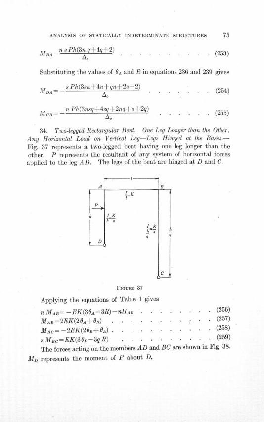
ANALYSIS OF STATICALLY INDETERMINATE STRUCTURES
MBA n s Ph(3n q+4q+2)AMBA
Substituting the values of OA and R in equations 236 and 239 gives
s Ph(3sn+4n+qn+-2s+2)MD = (3s +4s+2+s+2
=n Ph(3nsq±4sq±2nq-s±2q)
* (254)
. (255)
34. Two-legged Rectangular Bent. One Leg Longer than the Other.Any Horizontal Load on Vertical Leg-Legs Hinged at the Bases.-
Fig. 37 represents a two-legged bent having one leg longer than theother. P represents the resultant of any system of horizontal forcesapplied to the leg AD. The legs of the bent are hinged at D and C.
FIGURE 37
Applying the equations of Table 1 gives
nMAB= -EK(30A-3R)-nHAD . . . . . . . . (256)
MAB=2EK(20A+OB) . . . . ... * : . . (257)
MBc= -2EK(20B+OA) . . . . . ........ . (258)
s MBc= EK(3OB-3q R) . . . . . . . . . . (259)
The forces acting on the members AD and BC are shown in Fig. 38.
MD represents the moment of P about D.
(253)
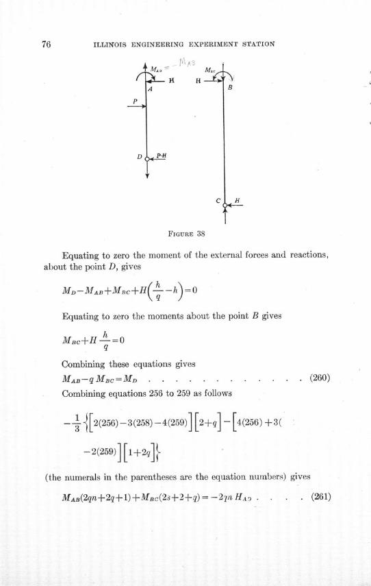
76 ILLINOIS ENGINEERING EXPERIMENT STATION
P
D
* A.4 A c- H HI
A
P-H
C
B
J-
FIGURE 38
Equating to zero the moment of the external forces and reactions,about the point D, gives
MD-MAB+MBC+H -hh =0
Equating to zero the moments about the point B gives
MBc+H h-=0q
Combining these equations gives
MAB-qMBC=MD . . . . . . .... . . . (260)
Combining equations 256 to 259 as follows
-- + 2(256) -3(258) -4(259) [2+q -[4(256) +3(
-2(259) N[1+2q]
(the numerals in the parentheses are the equation numbers) gives
MAB(2qn+ 2 q+l)+MBc(2s+2+q)= -27n HA . . (261)
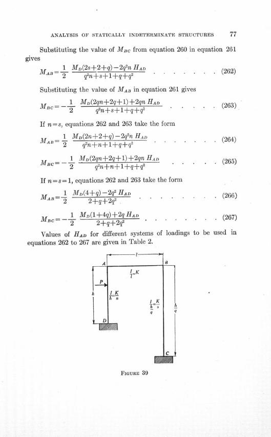
ANALYSIS OF STATICALLY INDETERMINATE STRUCTURES 77
Substituting the value of MBc from equation 260 in equation 261gives
MA = 1 MD(2s+2+q)-2q2n HAD (262)T q2n+s+l+qq 2
Substituting the value of MAB in equation 261 gives
MBC= - 1 M,(2qn+2q+1)+2qn HAD (263)2 q2n+s1++q+q2
If n= s, equations 262 and 263 take the form
1 MD(2n+2+q)-2q2n HAD. . (264)MAB=-~- "• q2n+n+l+qAq2. . . . . . .
1 MD(2qn+2q+1)+2qn HAD (265)Mo = 2 gn+n+1+q+q2
If n = s= 1, equations 262 and 263 take the form
1 MD(4+q)-2q2 HAD (266)MAB=- 2+q+2q2
1 MD(1+4q)+2q HAD . (267MBc 2 2+q+2q2 . . . . . .
Values of HAD for different systems of loadings to be used in
equations 262 to 267 are given in Table 2.
FIGURE 39
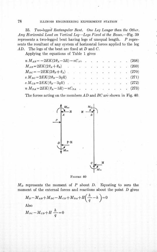
ILLINOIS ENGINEERING EXPERIMENT STATION
35. Two-legged Rectangular Bent. One Leg Longer than the Other.Any Horizontal Load on Vertical Leg-Legs Fixed at the Bases.-Fig. 39represents a two-legged bent having legs of unequal length. P repre-sents the resultant of any system of horizontal forces applied to the legAD. The legs of the bent are fixed at D and C.
Applying the equations of Table 1 gives
n MAB= -2EK(20A-3R) -nCA r,
MAB=2EK(20A+0) . . . .
MBc= -2EK(20B+OA) . . . .
s MBc= 2EK(20B-3qR) . .sMcB=2EK(OB-3qR) . . . .n MDA=2EK(OA-3R)-nCDA . .
. . . . . (268)
. . . . . (269)
. . . . (270)
. . . . (271)
. . . . (272)
. . . . . (273)
The forces acting on the members AD and BC are shown in Fig. 40.
P
D
K
A
M.
B
P-H
MoA
H4-I
FIGURE 40
MD represents the moment of P about D. Equating to zero themoment of the external forces and reactions about the point D gives
MD-MAB+MBC-McD+MDA+H(---h )=0
Alsoh
MIW-MCD+H -=0q
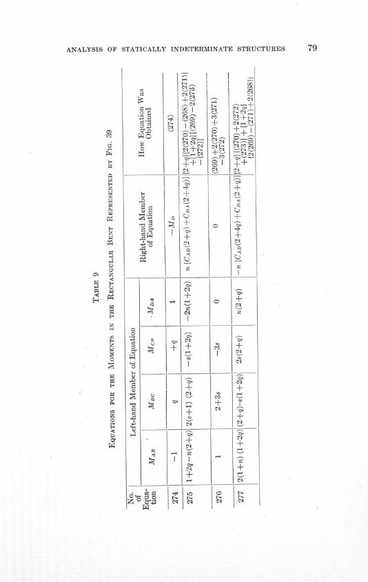
ANALYSIS OF STATICALLY INDETERMINATE STRUCTURES
z
w
W
rei
CI
E.i
z
Z
E-!
0
O z;
0
0
C)-a
C) 0
CWI
a
0
a,
C4-C)
SC)
-C
C)
0z
++t +
Cli
+a
I:
c•l
C-
+ +
00 CO'~
A-A- ' I'
I-^ t-
Cl i Cl
+
cl
-4 -4 0--
Cl C
CC
q ++ Cl
CO
'-45
+
Cl l Cl
00COCO
CO
^r-
C-g
^+
'5'
±Cl
C,g
+G
Cl
C,g
±
q
0
+
+Cl
'"i
+Cl
Cl
77 1 -
80 ILLINOIS ENGINEERING EXPERIMENT STATION
Combining these equations gives
MDA-MAB+q M -q MeD= -MD . . . . . . . (274)
Combining the equations as indicated gives the equations ofTable 9.
Solving these equations simultaneously gives
MAB =-'(MD- CDA) s (3s+ 4 +2q) - CAD(6q2ns+3s'+4s+qs
+2qn)1 . . . . . . . . . . . . . (278)
MHc= -=- (MD-CDA) s (3qn+2 +4q) + CAD (3qns- 2s - 2qs
-qn) . . . .. . . . . . . . . . . (279)
McB= -- o(MD CDA) (3qns+s+4qs+2qn+2q) +CAD(3qns -s
-- 2qs+2qn+4n- q)q . . . . . . . . .. (280)
MDA = -- l(MD - CDA) s (3ns+4n+qn +2s+2) +CAD (382+
4s(1+q+q2)+q2) - CDA . . . . . . . . . . (281)
A.= 2 1 ns(4+3q+4q2) + (82+s) +q(n 2+n) +3(q2sn2s2n)4 for equa-
tions 278 to 281 inclusive.
If n= s, equations 278 to 281 take the form
MAB 2=
1 (MD-CDA) (3n+4+2q) -CAD(6q 2n + 3n + 4 + q + 2q2)I
.. . . .. . . . . . . . . . .. (282)
Mac= - •{(Mfo-DCDA)(3qn+2+4q)+CAD(3qn-2-2q-q2) (283)
MCB= -- {(MD-CDA)(3qn 2+n+6qn+2q) +CAD(3qn2-n + q2n
-q)} . . . . . . . . . . . . . . (284)
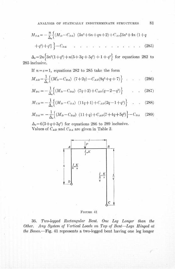
ANALYSIS OF STATICALLY INDETERMINATE STRUCTURES
MDA = - { ((MhI-CDA) (3n'+6n+qn+2)+CA,[3n2+4n (1+q
+q 2)+q 2] }-CA . . . . . . . . (285)
Ao= 2n3n2(1q 2)+n(5+ 3q + 5q2) 1 q for equations 282 to
285 inclusive.
If n= s= 1, equations 282 to 285 take the form
MAB= o{(MD-CDA) (7+2q)-CAD(8q2 ±q+ 7)}
MBc= -1 (MD-CDA) (7q+2)+CAD(q-2-q2) . .
McB= -l{ (MD-CD.) (llq+l)+CAD(2q-l+q2) . .
MDA= - {(M CDA) (11 +q)+CAD(7+4q+5q2)}--CDA
Ao=6(3+q+3q2) for equations 286 to 289 inclusive.Values of CAD and CDA are given in Table 2.
P
(286)
(287)
(288)
(289)
FIGURE 41
36. Two-legged Rectangular Bent. One Leg Longer than theOther. Any System of Vertical Loads on Top of Bent-Legs Hinged atthe Bases.-Fig. 41. represents a two-legged bent having one leg longer
82 ILLINOIS ENGINEERING EXPERIMENT STATION
than the other. P represents the resultant of any system of verticalloads applied to AB. The legs of the bent are hinged at C and D.
Applying the equations of Table 1 gives
nMAB= -EK(3 A- 3R) . . . . . . . (290)
MAB=2EK(20A+OB)-CAB .. . . . . . (291)
MBc= -2EK(2B+ OA)-CBA . . . . . . . .. . (292)
sMBc=EK(30B-3qR) .. . . . . . . . (293)
Since the sum of the shears in the two legs equals zero,
-MAB+qMBc=0 . . . . .. . . . ... . ,(294)
Combining equations 290 to 293 as follows
'-F -[ ] [2(290) -3(292) -4(293)1 31 ] [4(290)+3(291)-2(293)]
(the numerals in the parentheses are the equation numbers) gives
MAB(2qn+2q+ 1) +MBc(2s+2+q) =
-[CBA(2+q)+CAB(1+2q)] . . ... . (295)
Substituting Mac from equation 295 in equation 294 gives
q CBA(2+q)+CAB(1+2q) (29)MAB= (29=)
2 q2n+s+1+q+q2 . . . . .
Substituting MAB from equation 296 in equation 294 gives
• -1 CBA(2+q)+CAB(1+2q). (297MBc=-2 q2n+s+1+q+q2 . . .
FIf the load is symmetrical about the center of AB, CBA = CAB= -
and equations 296 and 297 take the form
MAB= - 3 F 1+q (298)2 1 q2n+s+1±+q+q
3 F 1+qMBC= - 2 1 q2n+s+1+q+q . . . . . . . (299)
FValues of CAB, CBA, and- -are given in Tables 2 and 3.
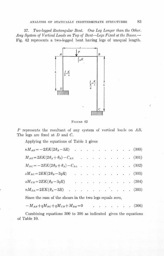
ANALYSIS OF STATICALLY INDETERMINATE STRUCTURES 83
37. Two-legged Rectangular Bent. One Leg Longer than the Other.Any System of Vertical Loads on Top of Bent-Legs Fixed at the Bases.-Fig. 42 represents a two-legged bent having legs of unequal length.
A
1K
h I K
I KD q
B
q
C
FIGURE 42
P represents the resultant of any system of vertical loads on AB.The legs are fixed at D and C.
Applying the equations of Table 1 gives
nMAB = - 2EK(2 0A - 3R) . . . . . . . . . . (300)
MAB=2EK(20A+fOB)-CAB . . . . . . . . . (301)
MBc= -2EK(20B+OA)-CBA . . . . . . . . . (302)
sMBc = 2EK(2 OB - 3qR) . . . . . . . . . . (303)
sMcB=2EK(OB-3qR) . . . . . . . . . . (304)
nMDA = 2EK(OA - 3R) . . . . . . ... . . . (305)
Since the sum of the shears in the two legs equals zero,
-MAB+qMBc+qMCB+MDA=O . . . . . . . (306)
Combining equations 300 to 306 as indicated gives the equationsof Table 10.
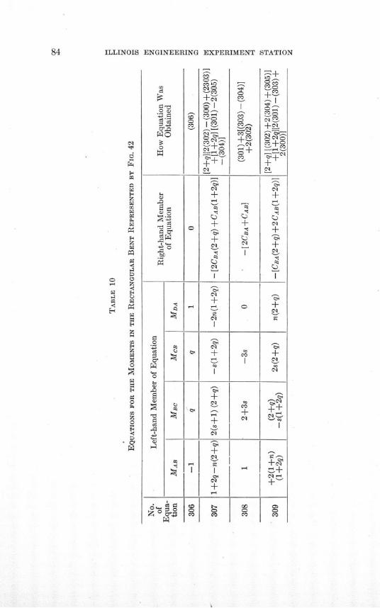
ILLINOIS ENGINEERING EXPERIMENT STATION
4..0
.0
4t
.04.0
C)
i 1A0
0
04
04
0 -Co Us
+ C1a I
cq
I
Co r
'7-
ceq
+Cs
C<1
cci
4.-0Co
0
+CY
cq
+,15
I
Cs-
0+Cm
eqs
ccCo
ccCo+eq
1-4
Co0Co
XC
ýz
57:7
C'o
clieq
eq÷04eq
+÷
v
I
Cs
+
'ci
04±eqcceq
0'
'- cc
co
ANALYSIS OF STATICALLY INDETERMINATE STRUCTURES 85
Solving these equations simultaneously gives
MAB = - -- - CBA [2qns(3+2q)+s2]+CAB[qns(3+8q)
+ 2 s2+2s+ 2 q2n] .. . . . . . . . . . (310)
Mc= - - CBA[ns(8+3q)+2q2n2+2q 2n+2s]
+CAB[2ns(2+3q)+qn ] . . . . . . (311)
MCB=- 4.- 1 CBA[ns(4+3q)-2q4n2 -2q 2n+s]
+CAB[2ns(1+3q) -qn 2+3qn] . . . . ... . (312)
1MDA = -- CBA[2qns(3+q) -s-+3qs]
+CAB[qns(3+4q)-2s2-2s+q2n] . . . . . . (313)
in which A= 2[ns(4+3q+4q2) +q 2n(3ns+n+1) +s(3ns+s+1)]F
If the load is symmetrical about the center of A B, CBA = CAB =
and equations 310 to 313 take the form
1 FMAB=.- TAl [3qns(3+4q)+3s2+2s+2qJn] . . . . (314)
MBC= - 1F [3ns(4+3q)+3q2n2+2q 2n+2s] . . . (315)
1 FMcB= Yo T [3ns(2+3q)-3q2n2+qn(3-2q)+s] . . (316)
1FMDA= - [3qns(3+2q)-3s2+s(3q-2)+q 2n] . . . (317)
If n=s equations 310 to 313 take the form
MAB=- CBAn(l+6q+4q2)+CAB[n(2+3q+8q2)
+2+2q2] . . . . . . . . . . . . . (318)
ILLINOIS ENGINEERING EXPERIMENT STATION
MBc= - tn CBA [n(8 + 3q + 2q2) + 2 + 2q2]
+CABn(4+6q+q 2) . . . . . . . . . . (319)
MCB= --- CBA [n(4 + 3q - 2q2) + 1 - 2q2]
+CAB[n(2+6q-q 2)+3q] . . . . . . .. . (320)
MDA CBA [n(-1 + 6q + 2q2) + 3q]
+CAB [n(-2+3q+4q2)-2+q 2] . . . . . . (321)
in which Ao 2n[3n2 (1+q 2) +n(5+3q+5q 2) +(1+q 2)]
FIf n=s and CBA=CAB= --- equations 310 to 313 take the form
nFMA= - --o - [3n(1+3q+4q2)+2+2q2] . . . . . (322)
- n FM2c= -o [3n(4+3q+q2)+2+2q2 ] . . . . .(323)
n nFMcB= -A l [3n(2+3q-q 2)+l+3q-2q 2] . . . . (324)
M D A [3n(-1+3q+2q2)-2+3q+q2] . . . (325)
FValues of CBA, CAB, and - are given in Tables 2 and 3.
38. Two-legged Rectangular Bent. One Leg Longer than theOther. External Moment at One Corner-Legs Hinged at the Bases.-Fig. 43 represents a two-legged rectangular bent having one leg longerthan the other. An external couple with moment M is applied at A.The legs are hinged at D and C.
Applying the equations of Table 1 gives
MAB= - (3A-3R)+M . . . . . . .. . (326)n
MAB=2EK(20A+0B) . . . . . . . . . . (327)
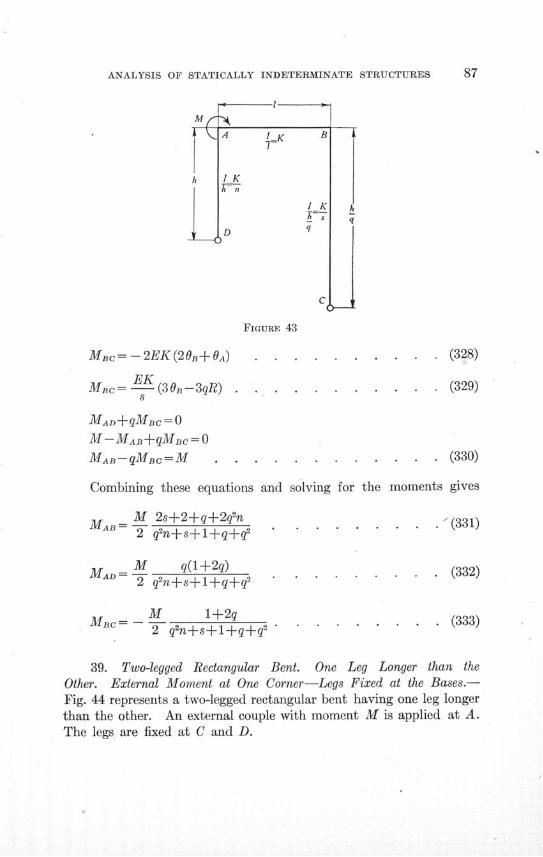
ANALYSIS OF STATICALLY INDETERMINATE STRUCTURES
FIGURE 43
MBc=-2EK(20B+OA) . . . . . . . . . . (328)
MBc= EK (3 3qR) . . . . . . . . . . . (329)Mc- (30n-3qR)....... . .... (329)
8
MAD+qMB = 0
M-MAB+qMBc=0
MAB-qMBc=M . . . . . . . . . . . . (330)
Combining these equations and solving for the moments gives
M M 2s+2+q+2q2n ,.3312 q2n+s+l+q+q2
MAD = M q(l+2q) . . . . . (332)2 qn+s+l+ q q'
Mc= - M +2 . . . . . . . (333)2 q2n+s+l+q+42
39. Two-legged Rectangular Bent. One Leg Longer than theOther. External Moment at One Corner-Legs Fixed at the Bases.-Fig. 44 represents a two-legged rectangular bent having one leg longerthan the other. An external couple with moment M is applied at A.The legs are fixed at C and D.
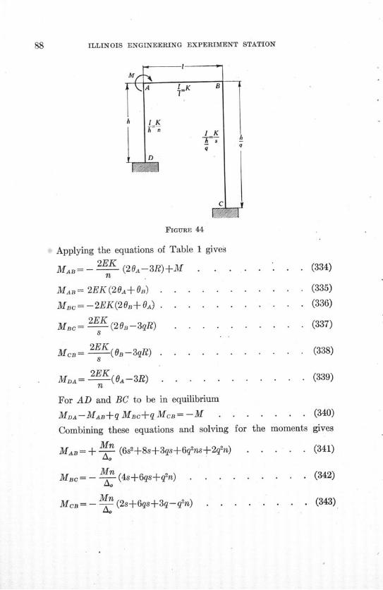
ILLINOIS ENGINEERING EXPERIMENT STATION
FIGURE 44
Applying the equations of Table 1 gives
MA= - (20A-3R)+M . . . . .n
MAB= 2EK (20A+ B) . . . . . . .
MBc= -2EK(2OB+ OA) ........
MBc= 2EK (2-3qR) . . . . . . .8
MCB= (O -3qR) . . . . . . . .
MDA= 2EK (0A-3R) . . . . . . . .n
For AD and BC to be in equilibrium
MDA-MAB+q MBc+qMcB= -M . . . .
Combining these equations and solving for the
MAB= + Mn (6s±+8s+3qs+6q ns+2qn) . .
MBc= -- (4s6qs+q2n) . . . . . .
MB= -Mn (2s+6qs+3q-q2n) . . . . .tao
. . . (334)
. . . (335)
. . . (336)
. . . (337)
. . . (338)
. . . (339)
. . . (340)
moments gives
. . . (341)
. . . (342)
(343)
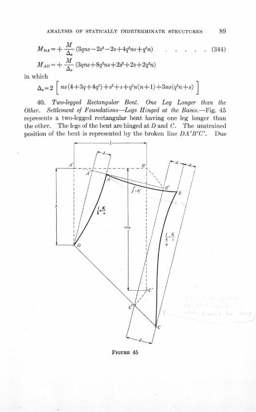
ANALYSIS OF STATICALLY INDETERMINATE STRUCTURES
MDA= + M (3qns-2s2 -2s+4q2 ns+q 2n) . . . . . (344)
MMAD= + ± (3qns+8q2ns+2s2+2s+2q2n)
in which
A,=2 [ns(4+3q+4q2) +s+s+q2n(n+1)+3ns(q2n+s)
40. Two-legged Rectangular Bent. One Leg Longer than theOther. Settlement of Foundations-Legs Hinged at the Bases.-Fig. 45represents a two-legged rectangular bent having one leg longer thanthe other. The legs of the bent are hinged at D and C. The unstrainedposition of the bent is represented by the broken line DA'B'C'. Due
FIGURE 45
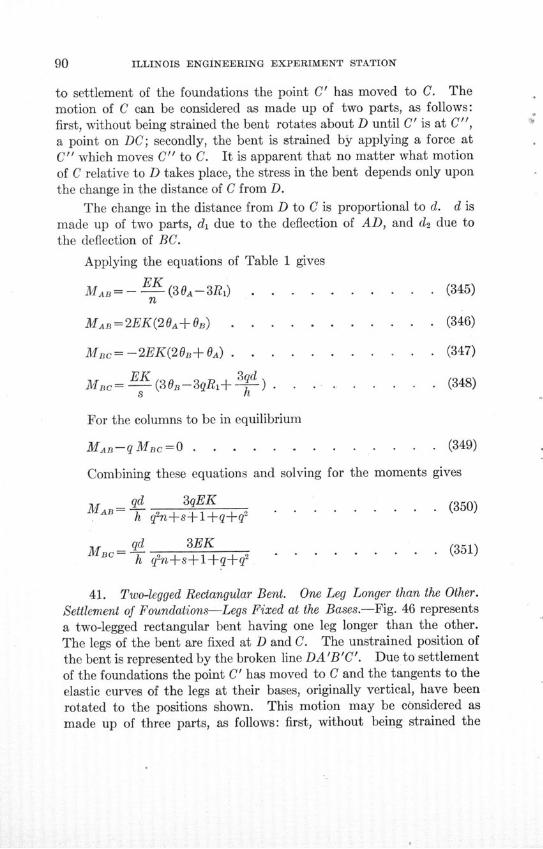
ILLINOIS ENGINEERING EXPERIMENT STATION
to settlement of the foundations the point C' has moved to C. Themotion of C can be considered as made up of two parts, as follows:first, without being strained the bent rotates about D until C' is at C",a point on DC; secondly, the bent is strained by applying a force atC" which moves C" to C. It is apparent that no matter what motionof C relative to D takes place, the stress in the bent depends only uponthe change in the distance of C from D.
The change in the distance from D to C is proportional to d. d ismade up of two parts, di due to the deflection of AD, and d2 due tothe deflection of BC.
Applying the equations of Table 1 gives
MB- K (30A--3R) . ......... (345)n
MAB=2EK(20A+0B) . . . . . . . . . . . (346)
MBc= -2EK(20+ OA) . . . . .. . . . . . (347)
EKqdMBC= - (30B-3qRi+ h ) . . . . . . . . . (348)
For the columns to be in equilibrium
MAB-qMBc . .=0........... .. (349)
Combining these equations and solving for the moments gives
MA = qd 3qEK . . . (350)h q2n+s+l+q+q2
M qd 3EK .q.
MBC 3EK . . . . . . . (351)h q2n+s+l+q+q2
41. Two-legged Rectangular Bent. One Leg Longer than the Other.
Settlement of Foundations-Legs Fixed at the Bases.-Fig. 46 representsa two-legged rectangular bent having one leg longer than the other.The legs of the bent are fixed at D and C. The unstrained position ofthe bent is represented by the broken line DA'B'C'. Due to settlementof the foundations the point C' has moved to C and the tangents to theelastic curves of the legs at their bases, originally vertical, have been
rotated to the positions shown. This motion may be considered asmade up of three parts, as follows: first, without being strained the
ANALYSIS OF STATICALLY INDETERMINATE STRUCTURES
bent rotates about D until C' is at C", a point on DC; secondly, the bentis strained by applying a force at C" which moves C" to C; thirdly,couples are applied at D and C, still further straining the bent so thatthe tangents to the elastic curves at the bases of the legs make anglesof OD and 6c respectively with lines normal to DC. It is apparent that,
FIGURE 46
no matter what motion of C relative to D takes place, the stress in thebent depends only upon the change in the distance from C to D andupon the angles O0 and Oc.
The change in the distance from D to C is proportional to d. d ismade up of two parts, di due to the deflection of AD, and d2 due to thedeflection of BC.
ILLINOIS ENGINEERING EXPERIMENT STATION
Applying the equations of Table 1 gives
2EKMAB= -2 (20A+OD-3R1) . . . . . . . . (352)
n
MAB=2EK(20,+B) ............ (353)
MBc= -2EK(20B+0A) . . . . . . . . . . . (354)
MBc=- (2OsB+c-3R2) . . . . . . . . . (355)8
2EKMCB= 2 (20c+OB-3R2 ) . . . . . . . . . (356)
8
MDA=-2 (20D +±A-3R 1)) ......... (357)
For the legs of the bent to be in equilibrium
MDA-MAB+qMBc+qMCB=O . ...... . (358)
Combining these equations and solving for the moments gives
MA=B 2E K 13!- [6qns+2qn-s] + Oc [9qns+2qn(3+q) - s]
-OD [6q2ns+2q2n-s(4+3q)-3s2] I . . . . . (359)
MBc= 2 E K 3 d [6ns-qn+ 2s] + Oc [6ns - qn (3+4q) +2s-3q2n2 ]
-0D [9qns-q2n+2s(1+3q)] . . . . . . . (360)
2EKlqdMcB= 2 - K• 3 d [6ns+n(4+q)+2s+1] + Oc [12ns + 2n(6 + 3q
+2q 2)+4s+3q2n2+3] - OD [9qns+qn(6+q) +s(1+6q)+3q] t
. . . . . . . . . . . . . . . . (361)
MDA= - 2EK-13 [6qns+2qn+s(1+4q)+q] + Oc [9qns+qn (6+q)
+s(1+6q) +3q] - D [12qns+42n+2s (2+3q+6q2) +3s+32] 1
. . . . . . . . . . . . . . . . (362)
ANALYSIS OF STATICALLY INDETERMINATE STRUCTURES
in which
Ao= 2 [ns(4+3q+4qf2)+n(3ns+n+1)+s(3ns+s+1)]
It is to be noted that Oc and 0D are measured, not from the original
direction of AD and BC, but from a line normal to AB.If the tangents to the elastic curves of the legs at their bases remain
vertical the moments can be expressed in terms of the vertical settle-ment of C relative to D. The O's are then measured from the originaldirection of AD and BC and equal zero. The displacement d is meas-ured in a -horizontal direction. Proceeding as before the moments arefound to be as follows:
M, 2 EK J3qd - 3 d3 [2n(134q)A= -- h [6qsf2n-s] (4+5q)7 [ns(13-4g)
+2qn(2+6q+q 2)+2s(9+q-q2) +s2(13-4q)] . . . (363)
MIc 2 EK 3 q 3 d3MBc2K 1d - [6ns-qn+2s] + (4 d [ns (4 + 5q)-o h (4+5q) 1
+ 2qn (1+5q+3q2) +2s (5+6q-2q2)+q2 n2(4+5q)] . (364)
M 2 EK t3qd 3 d [MCB= [6ns+n(4+q) +2s+1]- _ 3 d [ns (4+5q)
+n (8 + 16q + 15q2+6q 3) - s(3 + 10q - 4q2) + qn 2 (4+5q)
-2(1-2q+q2)]4 . ........ . . (365)
A2EK 3 a 3 d 3MD A 2-- 3 [6qns+2qn+s(1+4q) + q]- (4- q) [qns
(13-4q) -qn(4+2q+3q2)+s(18+15q+20q2 -8q 3) s2(13 -4q)
+2q(1-2q+q2)]4 . . . . . . . . . . . (366)
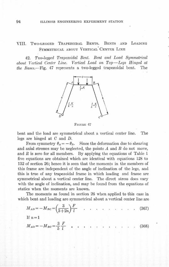
ILLINOIS ENGINEERING EXPERIMENT STATION
VIII. TWO-LEGGED TRAPEZOIDAL BENTS. BENTS AND LOADING
SYMMETRICAL ABOUT VERTICAL CENTER LINE
42. Two-legged Trapezoidal Bent. Bent and Load Symmetricalabout Vertical Center Line. Vertical Load on Top-Legs Hinged atthe Bases.-Fig. 47 represents a two-legged trapezoidal bent. The
FIGURE 47
bent and the load are symmetrical about a vertical center line. Thelegs are hinged at C and D.
From symmetry OA = - 0 B- Since the deformation due to shearingand axial stresses may be neglected, the points A and B do not move,and R is zero for all members. By applying the equations of Table 1five equations are obtained which are identical with equations 128 to132 of section 26; hence it is seen that the moments in the members ofthis frame are independent of the angle of inclination of the legs, andthis is true of any trapezoidal frame in which loading and frame aresymmetrical about a vertical center line. The direct stress does varywith the angle of inclination, and may be found from the equations ofstatics when the moments are known.
The moments as found in section 26 when applied to this case inwhich bent and loading are symmetrical about a vertical center line are
MAD =--M ( 3- F . . . . . ... . . (367)
If n=l1
3FMAD -MBc 5 1- .- ... .......... (368)
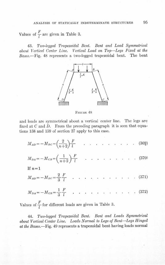
ANALYSIS OF STATICALLY INDETERMINATE STRUCTURES
FValues of - are given in Table 3.
43. Two-legged Trapezoidal Bent. Bent and Load Symmetricalabout Vertical Center Line. Vertical Load on Top-Legs Fixed at theBases.-Fig. 48 represents a two-legged trapezoidal bent. The bent
FIGURE 48
and loads are symmetrical about a vertical center line. The legs arefixed at C and D. From the preceding paragraph it is seen that equa-tions 158 and 159 of section 27 apply to this case.
(369)
(370)
MAD= -MBc=( )
MA= -MC=( 1 )
If n=1
2FMAD = -MBC=---
M1 3
MDA= -MCB=- --
. (371)
. (372)
FValues of for different loads are given in Table 3.
T
44. Two-legged Trapezoidal Bent. Bent and Loads Symmetricalabout Vertical Center Line. Loads Normal to Legs of Bent-Legs Hinged
at the Bases.-Fig. 49 represents a trapezoidal bent having loads normal
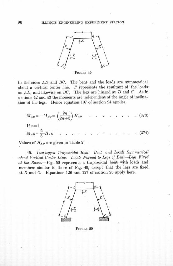
ILLINOIS ENGINEERING EXPERIMENT STATION
FIGURE 49
to the sides AD and BC. The bent and the loads are symmetricalabout a vertical center line. P represents the resultant of the loadson AD, and likewise on BC. The legs are hinged at D and C. As insections 42 and 43 the moments are independent of the angle of inclina-tion of the legs. Hence equation 107 of section 24 applies.
MAD-MBC= (2 H . . . . . . . . (373)
If n=1
MaD = 2•HAD . ............ (374)
Values of HAD are given in Table 2.
45. Two-legged Trapezoidal Bent. Bent and Loads Symmetricalabout Vertical Center Line. Loads Normal to Legs of Bent-Legs Fixedat the Bases.-Fig. 50 represents a trapezoidal bent with loads andmembers similar to those of Fig. 49, except that the legs are fixedat D and C. Equations 126 and 127 of section 25 apply here.
FiGaUz 50

ANALYSIS OF STATICALLY INDETERMINATE STRUCTURES
MAD=-Mnc= (T- ) CAD . . . . . . . . . (375)
MDA MCB=- +D D . . . . . . (376)
If n=l11
MAD=-MBC= 1 CAD ...... . . . . (377)3
MDA=-MB=- ( A+CA) . . . . . .. . (378)
Values of C are given in Table 2.
46. Two-legged Trapezoidal Bent. Bent and Loads Symmetricalabout Vertical Center Line. External Moments at Upper Corners ofBent-Legs Hinged at the Bases.-Fig. 51 represents a two-legged trape-
FIGURE 51
zoidal bent having couples acting at A and B. The bent and thecouples are symmetrical about a vertical center line. The legs arehinged at C and D.
As in sections 42 and 43 because of the symmetry of loads andbent, the moments are independent of the angle of inclination of the
legs. Equations 163 and 164 of section 28 are modified to applyhere by the algebraic addition of moments due to the two couples.
MAD = 3M . . . ........ . . . . (379)
S2n+3
MA= 2n" .. ....... ..... .(380)Mx 2n+3].. .
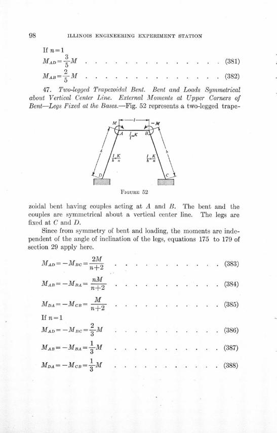
98 ILLINOIS ENGINEERING EXPERIMENT STATION
If n=13
MAD-M . .-M .............. (381)
2MAB = 5 M .............. (382)
47. Two-legged Trapezoidal Bent. Bent and Loads Symmetricalabout Vertical Center Line. External Moments at Upper Corners ofBent-Legs Fixed at the Bases.-Fig. 52 represents a two-legged trape-
FIGURE 52
zoidal bent having couples acting at A and B. The bent and thecouples are symmetrical about a vertical center line. The legs arefixed at C and D.
Since from symmetry of bent and loading, the moments are inde-pendent of the angle of inclination of the legs, equations 175 to 179 ofsection 29 apply here.
2MMAD = -MBC- . .n--2 . .......... .. (383)
MAB = -MBA nMM±..=--MB..=.......--2...........(384)
MMDA = -MCB= n2 . . . . . . . . . . . (385)
If n=l12
MAD= -MBC = -M . . .. . . . . . . (386)
1MAB=-MBAM=- 1M . .......... (387)
1MDA = -MCB = 1-M . ........... (388)
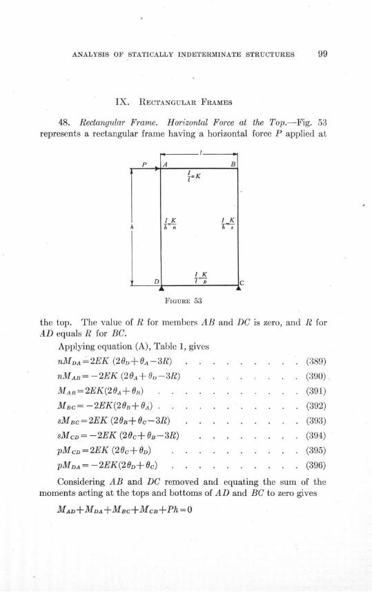
ANALYSIS OF STATICALLY INDETERMINATE STRUCTURES
IX. RECTANGULAR FRAMES
48. Rectangular Frame. Horizontal Force at the Top.-Fig. 53represents a rectangular frame having a horizontal force P applied at
FIGURE 53
the top. The value of R for members AB and DC is zero, and R forAD equals R for BC.
Applying equation (A), Table 1, gives
nMDA=2EK (20D+OA-3R) . . . . . . . . . (389)
nMAB= -2EK (20A+O-3 3R) . . .. . . . . (390)
MAB=2EK(20A+O6) . . . . . .. . . . (391)
MBc= -2EK(206B+OA) .. . . . . . .. . (392)
sMnBc=2EK (20 B+0c-3R) . . . . . . . . . (393)
sMcD= -2EK (20c+OB-3R) . . . . . . . . (394)
pMcD= 2EK (20c+OD) . . . . . . . . . . (395)
pMDA = -2EK(20D+ c) . . . . . . . . . . (396)
Considering AB and DC removed and equating the sum of themoments acting at the tops and bottoms of AD and BC to zero gives
MAD+MDA+MBC+MCB+Ph = 0
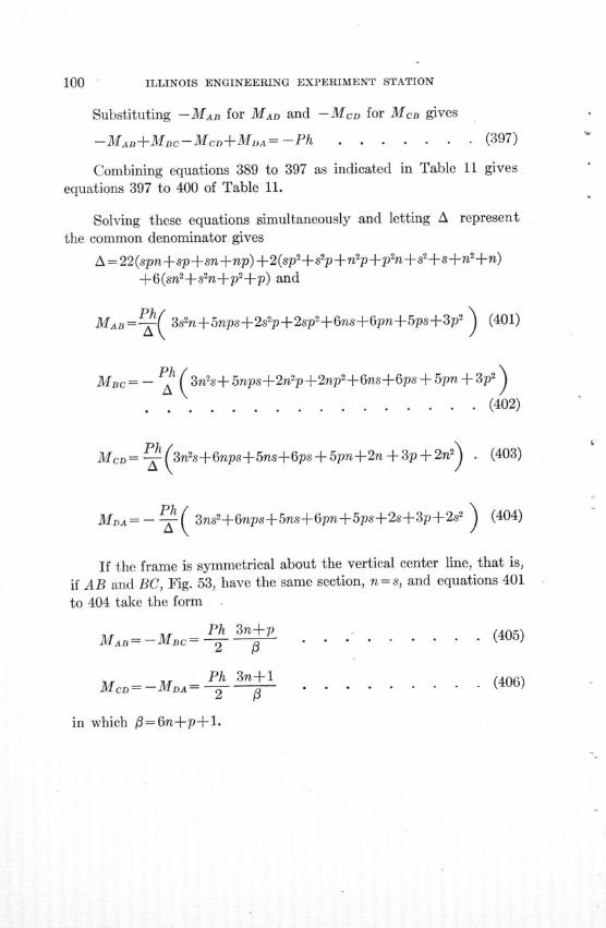
ILLINOIS ENGINEERING EXPERIMENT STATION
Substituting -MAB for MAD and -MCD for McB gives
-MAB+MBC-MCD+MDA=-Ph . . . . . . . (397)
Combining equations 389 to 397 as indicated in Table 11 gives
equations 397 to 400 of Table 11.
Solving these equations simultaneously and letting A represent
the common denominator gives
A= 22(spn+sp+sn+np)+2(sp2+s2p+n±p+p2n2+s+s+nl2 +n)
+6(sn 2+s 2n+p 2+p) and
MAB=PP.( 3s2n+5nps+2s2p+ 2 sp2+6ns+6pn+5ps+3p2) (401)
Mac= - h( 3ns+5nps+2n'p+2np2+6ns+6ps + 5pn + 3p2)
. . . . . . . . . . . . . . . . (402)
McD= - (3n2s+6nps+5ns+6ps+ 5pn+ 2 n + 3 p + 2n) . (403)
MDA= - P_( 3ns2+6nps+5ns+6pn+5ps+2s+3p+2s2 ) (404)
If the frame is symmetrical about the vertical center line, that is,
if AB and BC, Fig. 53, have the same section, n = s, and equations 401
to 404 take the form
MAP=-M = 2 . . . . . ..... (405)
MCD-M=MD.. Ph 3n+1 . (406)in which =6+p....... .. (406)
in which f3=6n+p+1.
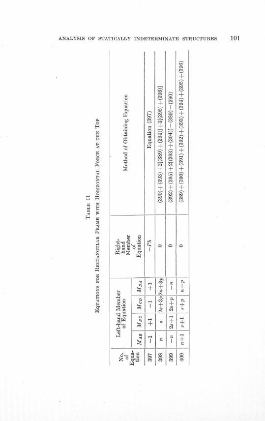
ANALYSIS OF STATICALLY INDETERMINATE STRUCTURES 101
o
0
z
0
0
C,z
0
§
0g
o-
Oi.<
o
~0bO
't5
0P
CD.0
o
-0
T3.il•
~020
I. §1,
§"§q
Zz l
I
CO
0
0
_0
'+>
I---
CO
CO
CO±+
COm
CO'
+CO
00CO
+Cm+CO
CO
+
CO
0CO
000CO
0
CO
+CO0CO
+COCCO
+CCO
0
0
+Co
0
CCCO
CO
+CO
+eCO
+
+
+CO
C
+
CO
+COCO
CO
+
CO
0
+
+CO
o÷÷•o
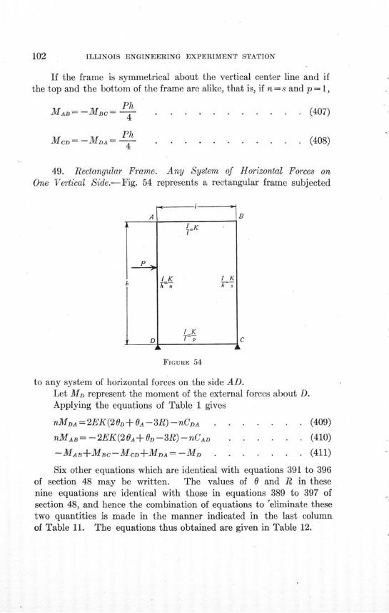
ILLINOIS ENGINEERING EXPERIMENT STATION
If the frame is symmetrical about the vertical center line and ifthe top and the bottom of the frame are alike, that is, if n = s and p = 1,
MAB= -MBC= PhcM 4
McD = -MDA Ph--4
. . . . (407)
. (408)
49. Rectangular Frame. Any System of Horizontal Forces onOne Vertical Side.-Fig. 54 represents a rectangular frame subjected
D
I=K7-
1K K
I KT7___
FIGURE 54
to any system of horizontal forces on the side AD.Let MD represent the moment of the external forces about D.Applying the equations of Table 1 gives
nMDA=2EK(2D+ OA-3R)-nCDA . . .
nMAB= -2EK(20A +D-3R)-nCAD . .
-MAB+MBC-MCD+MDA = -MD . . .
. . (409)
. . (410)
S. (411)
Six other equations which are identical with equations 391 to 396of section 48 may be written. The values of 0 and R in thesenine equations are identical with those in equations 389 to 397 ofsection 48, and hence the combination of equations to 'eliminate thesetwo quantities is made in the manner indicated in the last columnof Table 11. The equations thus obtained are given in Table 12.
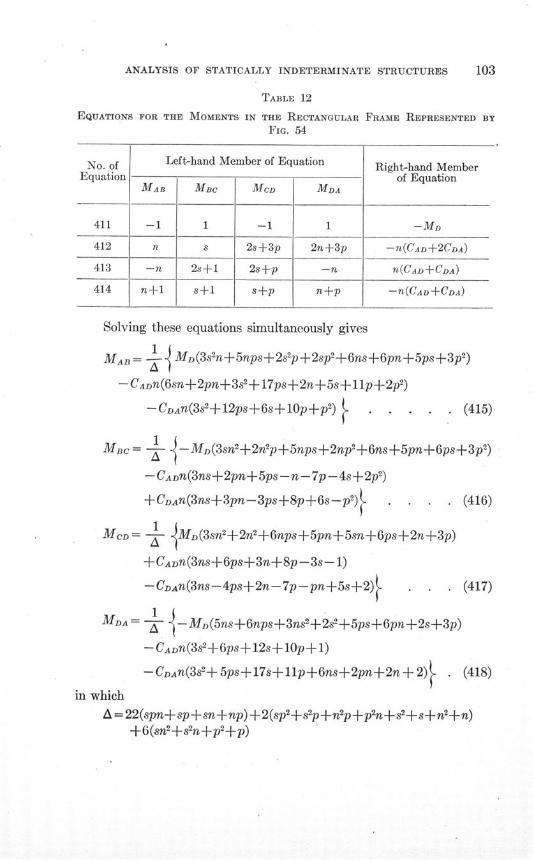
ANALYSIS OF STATICALLY INDETERMINATE STRUCTURES 103
TABLE 12
EQUATIONS FOR THE MOMENTS IN THE RECTANGULAR FRAME REPRESENTED BY
FIG. 54
No. of Left-hand Member of Equation Right-hand MemberEquation of Equation
MAB Mac MCD MDA
411 -1 1 -1 1 -MD
412 n s 2s+3p 2n+3p -n(CAD+2CDA)
413 -n 2s+1 2s+p -n n(CAD+CDA)
414 n+1 s+1 s+p n+p -n(CAD+CDA)
Solving these equations simultaneously gives
MAB= - t MD(3s'n+5nps+2s'p+2sp2+6ns+6pn+5ps+3p')
-CADn(6sn+2pn+3s2+17ps+2n+5s+lp+ 2 p2 )
-CDAn(382+12ps+6s+10p+p2) .. . . (415)
MBC= - M.,M(3sn2+2n2p+5nps+2np2+6ns+5pn+6ps+3p2)
-CADn(3ns+2pn+5ps-n-7p- 4 s+ 2 p 2)
+CDAn(3ns+3pn-3ps+8p+6s-p2) . . . . (416)
MCD = jMD(3snh+2n2+6nps+5pn+5sn+6ps+2n+3p)
+CADn(3ns+6ps+3n+8p-3s- 1)
-CDAnf(3ns-4ps+2n-7p-pn+5s+2) . . . (417)
MDA= -- -MD(5ns+6nps+3ns2+2s2+5ps+6pn+2s+3p)
- CADn(3s2+6ps+12s+10p+1)
-CDAn(3s'+ 5ps+17s+llp+6ns+2pn+2n + 2) . (418)
in which
A =22(spn+sp+sn+np)+2(sp2+s 2p+n 2p+p 2n+s 2+s+n 2 +n)+6(sn 2+s 2n+p 2+p)

104 ILLINOIS ENGINEERING EXPERIMENT STATION
If n= s, equations 415 to 418 take the form
MAB= - CDn[ + +CDAn[-+T -MD 'np
. . . . . . . . . . . . . . . . (419)
MB 1 C[n+2p 3 -CDA 3 3n+p
aa 1a 3
MCD=1 1 3- CADn[1 -]- + nCDAn ["+2 3 -M 3 n +1
. . . . . . . . . . . . . . . . (421)
MDA- = 1C n [_ 3 + r] Dn+2 +l 3 + ±M , 3n+1l
. . . . . . . . . . . . . . . . (422)in which
a=n-+2pn+2n+3pf= 6n+p+l
If n = s and p = 1 equations 419 to 422 take the form
MA 1 rCADn+2 3 • DAn[ + 1 3 - M D
. . . . . . . . . . . . . . . . (423)
MBC1 (+ [n+ 2 3 ]+CDn[ 1 3 ]1 MDMac= 2-CADn DA J - +
. . . . . . . .. . . . . . . .. . (424)
1 1 3 +2 3. n MDMcD=- 2 CADn [ a +CDARn -a \2
. . . . . . . . . . . . . . . . (425)
MDA=-T.CADn + ±-0+C.An + +J D
. . . . . . . . . . . . . . . . (426)
in whicha= (n+3) (n+1)#3=2(3n+l)
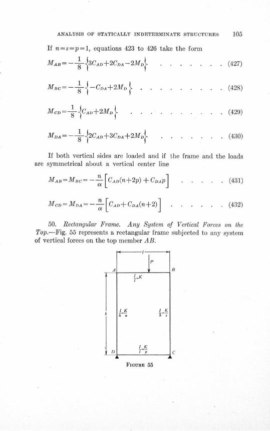
ANALYSIS OF STATICALLY INDETERMINATE STRUCTURES
If n=s= p=l, equations 423 to 426 take the form
MAB= -- 3CAD+2CDA--2MD . . . . . . . (427)
MBc=-- - -CDA+2MD . . . . . . . . . (428)
McD= - CAD+2M. . . . . . . . . . . (429)
MDA= - -<J2CAD+3CDA+2MD.. . . . . . . . (430)
If both vertical sides are loaded and if the frame and the loadsare symmetrical about a vertical center line
MAB=MBC=- n [CAD(n+2p) +CDAP] . . . . . (431)
MCD =MDA= n- c [cAD+ CDA(n+2)] . . . . . . (432)
50. Rectangular Frame. Any System of Vertical Forces on theTop.-Fig. 55 represents a rectangular frame subjected to any systemof vertical forces on the top member AB.
A
D
1K 1K
A n 7t s
I K
T-p
B
C
FIGURE 55
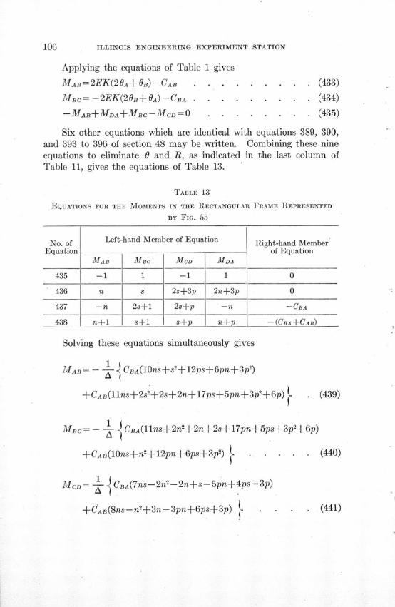
ILLINOIS ENGINEERING EXPERIMENT STATION
Applying the equations of Table 1 gives
MAB=2EK(20A+B) -CAB . . .
MBc= -2EK(20B+OA)-CBA . . .
-MAB+MDA+MBC-MCD=O . .
. . . . . (433)
. . . . . (434)
. . . . (435)
Six other equations which are identical with equations 389, 390,and 393 to 396 of section 48 may be written. Combining these nineequations to eliminate 0 and R, as indicated in the last column ofTable 11, gives the equations of Table 13.
TABLE 13
EQUATIONS FOR THE MOMENTS IN THE RECTANGULAR
BY FIG. 55
FRAME REPRESENTED
No. of Left-hand Member of Equation Right-hand MemberEquation of Equation
MAB MBC MCD MDA
435 -1 1 -1 1 0
436 n s 2 s+ 3 p 2n+3p 0
437 -n 2s+1 2s+p -n -CBA
438 n+1 s+1 s+p n+p -(CBA+CAB)
Solving these equations simultaneously gives
MAB= - CBA(10ns+s2+12ps+6pn+3p2')
+CAB(llns+2s 2+2s+2n+17ps+5pn+3p 2+6p) . (439)
MB= -- - CBA(llns+2n2+2n+2s+17pn+5ps+3p2+6p)
. (440)+CAB(10ns+n 2+12pn+6ps+3p') .
McD= CBA(7ns-2n2-2n+s-5pn+4ps-3p)
+CAB(8ns-n2+3n-3pn+6ps+3p) (441)
ANALYSIS OF STATICALLY INDETERMINATE STRUCTURES
MDA= CBA(8ns-2+3s-3ps+6pn+3p)
+CAB(7ns-2s'-2s+n--5ps+4pn-3p) . . . . (442)
in which
A =22(spn+sp+sn+np)+2(sp2+s 2p+n 2p+np2+S2+s+n2+n)
+6(sn2+s 2n+p2+p)
If the load is symmetrical about the center of AB, that is, ifCAB = CBA, equations 439 to 442 take the form
MAB = - - [21ns+3s2+2s+2n+29ps+11pn + 6p+6p2 (443)
Mnc= - 21ns+3n*+2n+2s+29pn+11ps+6p6p2 (444)
MCD= - 15ns-3n+n+s-8pn+10ps . . . . . (445)
MDA= 15ns-3s2+s+n-8ps+10pn . . . . (446)
If n = s equations 439 to 442 take the form
MA. 1 JCB 2n+3p 1 [2n+3p 1
1 [ 2n+3p 2+3p
MBc=- - -C [ 2 + +CI DA[ - . (448)2 a 3 I a
Mca-n 1 +CADAn n 1MDA= T]+ [DA+ +- . . . (450)
in which a = n+2pn+2n+3p
= 6n+p+l

ILLINOIS ENGINEERING EXPERIMENT STATION
If n= s and CAB =CBA
2n+3pMAB=MBC =-CAB 2.. . ........ (451)
MCD = MDA = CAB n (452)
If n = s and p= 1
1 2n+3 1 [2nr+3 1÷ .
Tf 1 < F2n+3 1 2n+3 1
MAB= - -' CBA + CAB + (453)
MBc= - 1 cBA [_ +..+ +C.[AB[U.--h-J (454)
MCD= -1- CBA - + - [AB . . . (455)
MA CBA + CAB- . . . . (456)
in which
a= (n+l) (n+3)
. =2(3n+l)
If n=s, p=l, and CAB=CBA
MAB=MBC= -CAB . (457)(n+ 1)y (n+3)(457)
McD = M( fAB . . . . . . . . (458)MC = MDA = CAB (n+l) (n + 3) (458)
If n=s=p= l
MAB=- -I2CBA+3CAB] . . . . . . . . . (459)
MBC= - [3CBA + 2CAB . . . . . . . . . (460)
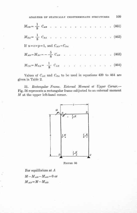
ANALYSIS OF STATICALLY INDETERMINATE STRUCTURES 109
1MCD= - CAB .............. (461)
1MDA= -=- CBA . .. .......... . (462)
If n=s=p=l, and CAB =CBA
MAB=MBC=-- CAB . . . . . . . . . . (463)8
MCD=MA= -- CAB . . . . . . . . . . (464)
Values of CAB and CBA to be used in equations 439 to 464 aregiven in Table 2.
51. Rectangular Frame. External Moment at Upper Corner.-Fig. 56 represents a rectangular frame subjected to an external momentM at the upper left-hand corner.
FIGURE 56
For equilibrium at A
M-MAB-MAD=O or
MAB=M-MAD
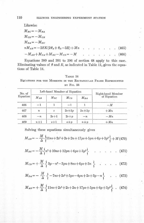
110 ILLINOIS ENGINEERING EXPERIMENT STATION
Likewise
MBc= -MBA
MCD= -MCB
MDA= -MDC
nMAB= -2EK(20A+ D-3R) +Mn . . . . . . . (465)
-MAB+MDA+MBC-MCD=-M . . . . .. . (466)
Equations 389 and 391 to 396 of section 48 apply to this case.Eliminating values of 0 and R, as indicated in Table 11, gives the equa-tions of Table 14.
TABLE 14
EQUATIONS FOR THE MOMENTS IN THE RECTANGULAR FRAME REPRESENTED
BY FIG. 56
No. of Left-hand Member of Equation Right-hand MemberNo. of Right-hand Member
Equation MAB MBC MCD MDA of Equation
466 -1 1 -1 1 -M
467 n s 2s+3p 2n+3p +Mn
468 -n 2s+l1 2s+p -n -Mn
469 n+1 s+1 s+p n+p +Mn
Solving these equations simultaneously gives
MAB= - M 11llns+2s2+2s+2n+17ps+5pn+6p+3p2 +M(470)
MBc=10 12 . . . . .(471)
MCD= + -- 3p-n 2-3pn+8ns+6ps+3n . . . . (472)
MDA=-- - -7ns+2s 2+5ps-4pn+2s+3p-n . . (473)
MAD=+~~M 11ns+2s2+2s+2n+17ps+5pn+6p+3p2 . (474)MAD=+ Y• (44
ANALYSIS OF STATICALLY INDETERMINATE STRUCTURES
in which
A=22(pns+sp+sn+np)+2(sp2+ s2p+n2p+,n +s 2+s+n2+n)+6(sn 2+s 2n+p 2+p)
If n = s, equations 470 to 474 take the form
M n(n+2p) 1(475)MAB - 1+ . . . . . . . (475)
MC= TM.n(n+2p) 6n+p . . .. . .. (476)
M + I . . . . . . . . . . (477)
M I . . . . . . . . (478)
M a ......
MAD= 1 n(n+2p) + 1 (479)
in which
a=n2+2pn+2n+3p
0=6n+p+l
If n = s and p=l, equations 475 to 479 take the form
M n(n+2) In±()MAB=-
- T 1+ (n+l) (n+3) 6n+2 ....... (480)
M n(n+2) + 1 (481)2 (n+l)(n+3) 6n.2
= +M n(2n+2) 6n+l (482)MBC= +2 (n+l)(n+3) 6n+2.
MM= + M n 1 . . . . (483)Mc=+2 (n+l)(n+3) +6n +2
112 ILLINOIS ENGINEERING EXPERIMENT STATION
MDA= 2 (n+l)(n+ 3 ) 6n±+2(
If n = s= p=1, equations 480 to 484 take the form
MAB=+.5.M ............. (485)
3MAD= +3M . . . .. . . . . . . . . (486)MAC=+ - M ... ....... (486)
MM .c.= --. .... . . . . . . . . . . . . (487)
Mc.D=+-.- . ...... ...... . (488)
MDA=0 . . . . . . . . . . . . . . (489)
If there is a couple at B as well as at A and if the frame and loadingare symmetrical about a vertical center line, that is, if the couples areequal in magnitude and opposite in sense, and if n= s
MnMA= -MBA= -- (n+2p) . . . . . . . . . (490)
MMAD= - MBC= - (2n+3p) . . . . . . . . . (491)
a
MCD = MDA= Mn . . . . . . . . . . . .. (492)aOI

ANALYSIS OF STATICALLY INDETERMINATE STRUCTURES
X. MOMENTS IN FRAMES COMPOSED OF A LARGE NUMBER OF
RECTANGLES AS A SKELETON-CONSTRUCTION BUILDING FRAME
52. Effect of Restraint at One End of a Member up6n Moment atOther End.-Fig. 57 represents any member in flexure. The end A is
MAB
FIGURE 57
acted upon by a couple MAB such that the tangent to the elastic curveat A makes an angle OA with AB. The magnitude of the moment MAB
depends not only upon the magnitude of OA, the moment of inertia ofthe section and the length of AB, but also upon the degree of restraintat B. This is illustrated by the following special problems.
Consider that AB is hinged at B. Applying equation (C) of Table1 with R and HAB equal to zero gives
MAB=3EK O . .......... . . (493)
Consider that AB is fixed at B. Applying equation (A) of Table1 with OB, R, and CAB equal to zero gives
MAB = 4EK OA . . . . . . . . . .. . . (494)
Consider that OA = - 0B. Applying equation (A) of Table 1 withR and CAB equal to zero and with OA = - O gives
MAB = 2EK OA . . . . .. . . ... . . . (495)
PB
FIGURE 58
I^
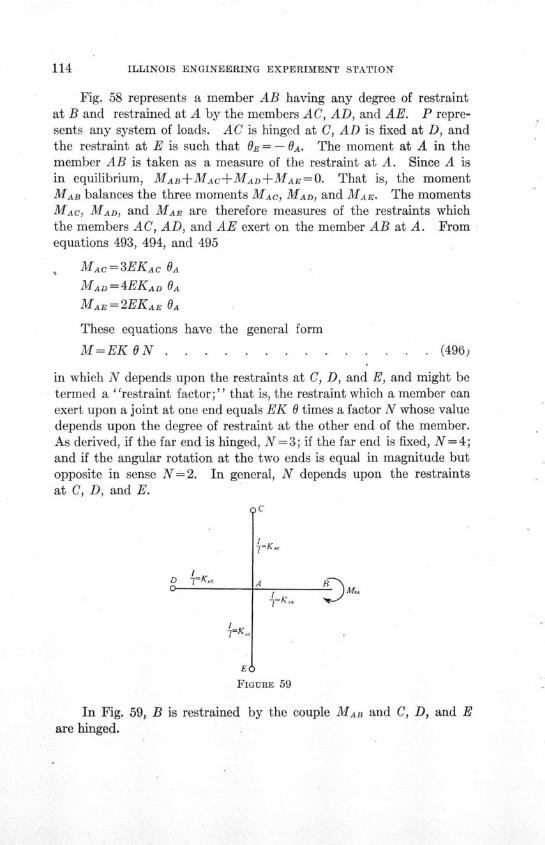
ILLINOIS ENGINEERING EXPERIMENT STATION
Fig. 58 represents a member AB having any degree of restraintat B and restrained at A by the members AC, AD, and AE. P repre-sents any system of loads. AC is hinged at C, AD is fixed at D, andthe restraint at E is such that OR = - OA. The moment at A in themember AB is taken as a measure of the restraint at A. Since A isin equilibrium, MAB+MAC+MAD+MAE=O. That is, the momentMAB balances the three moments MAC, MAD, and MAE. The momentsMAC, MAD, and MAE are therefore measures of the restraints whichthe members AC, AD, and AE exert on the member AB at A. Fromequations 493, 494, and 495
, MAC =3EKAC OA
MAD =4EKAD OA
MAE = 2EKAE OA
These equations have the general form
M=EK N ..... . . . . .... . (496)
in which N depends upon the restraints at C, D, and E, and might betermed a "restraint factor;'" that is, the restraint which a member canexert upon a joint at one end equals EK 0 times a factor N whose valuedepends upon the degree of restraint at the other end of the member.As derived, if the far end is hinged, N=3; if the far end is fixed, N =4;and if the angular rotation at the two ends is equal in magnitude butopposite in sense N=2. In general, N depends upon the restraintsat C, D, and E.
D 1=Ko70K
"IK
1C
LAKAt B~
r^ ^
EU
FIGURE 59
In Fig. 59, B is restrained by the couple MAD and C, D, and Eare hinged.
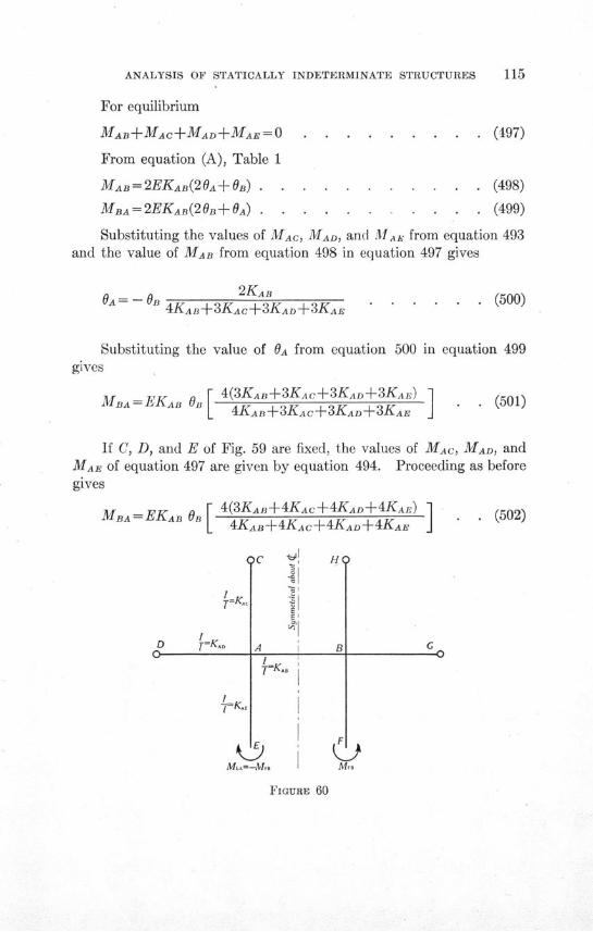
ANALYSIS OF STATICALLY INDETERMINATE STRUCTURES 115
For equilibrium
MAB+MAC+MAD+MAE = 0
From equation (A), Table 1
MAB= 2EKAB(20A+ GB)
MBA= 2EKAB(20a+ 0) . .
. (497)
* (498)
. (499)
Substituting the values of MAC, MAD, and MAAE from equation 493and the value of MAB from equation 498 in equation 497 gives
OA= _ GB 2KAB4KAB+3KAC+3KAD+3KAE
. . . (500)
Substituting the value of OA from equation 500 in equation 499gives
M _= EKAB B 4(3KAB+3KAc+3KAD+3KAE)MBA = EKAB OB 4KAB+3KAc+3KAD+3KAE I . (501)
If C, D, and E of Fig. 59 are fixed, the values of MAC, MAD, andMAE of equation 497 are given by equation 494. Proceeding as beforegives
MBA= EKAB O 4(3KAB+4KAc+4KAD+4KAE)I 4KAB+4KAC+4KAD+4KAE J
D =K-
IK
4
A
F.
. (502)
-
M'sMui-M 60
FIGURE 60
I
4 ,F k
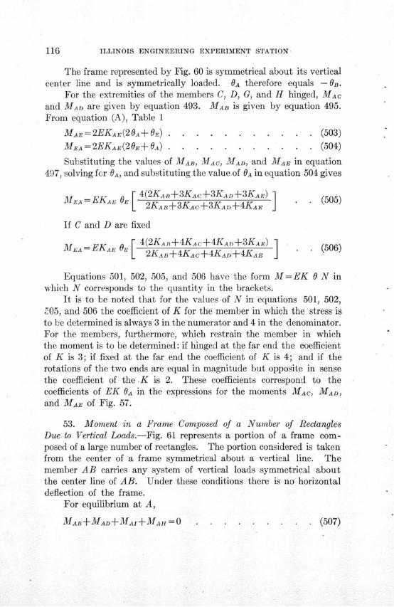
ILLINOIS ENGINEERING EXPERIMENT STATION
The frame represented by Fig. 60 is symmetrical about its verticalcenter line and is symmetrically loaded. OA therefore equals - OB.
For the extremities of the members C, D, G, and H hinged, MACand MAD are given by equation 493. MAB is given by equation 495.From equation (A), Table 1
MAE= 2EKAE(2A+OE) . . . . . . . . . . . (503)
MEA = 2EKAE(2OE OA) . . . . . . . .. . . .(504)
Substituting the values of MAB, MAC, MAD, and MAE in equation497, solving for OA, and substituting the value of OA in equation 504 gives
MEA = EKE OE 4(2KAB+3KAc+3KAD+3KAE) 1MEA = EKAE RE O I (505)L 2KAB+3KAC+3KAD+4KAE J
If C and D are fixed
M•A = EKA O [ 4(2KAB+4KAc+4KAD+3KAE) (506)K 2KAB+4KAc+4KAD+4KABE J
Equations 501, 502, 505, and 506 have the form M=EK 0 N inwhich N corresponds to the quantity in the brackets.
It is to be noted that for the values of N in equations 501, 502,"05, and 506 the coefficient of K for the member in which the stress isto be determined is always 3 in the numerator and 4 in the denominator.For the members, furthermore, which restrain the member in whichthe moment is to be determined: if hinged at the far end the coefficientof K is 3; if fixed at the far end the coefficient of K is 4; and if therotations of the two ends are equal in magnitude but opposite in sensethe coefficient of the .K is 2. These coefficients correspond to thecoefficients of EK OA in the expressions for the moments MAC, MAD,
and MAE of Fig. 57.
53. Moment in a Frame Composed of a Number of RectanglesDue to Vertical Loads.-Fig. 61 represents a portion of a frame com-posed of a large number of rectangles. The portion considered is takenfrom the center of a frame symmetrical about a vertical line. Themember AB carries any system of vertical loads symmetrical aboutthe center line of AB. Under these conditions there is no horizontaldeflection of the frame.
For equilibrium at A,
MA+MAD+MAI+MAH = 0 . (507)

ANALYSIS OF STATICALLY INDETERMINATE STRUCTURES 117
0 .
77 K,
N I-
L = KIL
K I
-=KK,
H
'- iK.I=K-
A BI
D C'LK
G
S P
Q
/ I R
FIGURE 61
From equation 496, section 52
MAD = EKAD OA NAD ... .. . . . . . . (508)
MAI=EKAI OA NAI . . . . . . . ... . (509)
MAH=EKAH ANAH . .. ... . . . . . (510)
Substituting the values of MAD, MAI, and MAH from equations 508,509, and 510 in equation 507 gives
MAB= -E OAKAD NAD+KAI NAI+KAH NAH . . . (511)
Since the frame is symmetrical about a vertical center line, Oa= - OB.From equation (C) of Table 1
MAB=2EKAB GA- - . .... . . . . (512)
Eliminating OA from equations 511 and 512 gives
MA F [KANAD+KA NAI+KAHNAH (513)A KAD NAD+KAz NA+KAI•NAH+2KA,.] *
7=Ka
1 .
fVl
ILLINOIS ENGINEERING EXPERIMENT STATION
The stress in the frame apparently depends upon the values of theN's in equation 513; that is, the stress depends upon the degrees ofrestraint of the extremities of the members, 0, N, L, K, J, etc.
Although the degrees of restraint at these extremities are not known,it is known that the degree of restraint at each extremity is greaterthan if the extremity is hinged and less than if the extremity is fixed.If then the stresses are determined with the extremities hinged andagain with the extremities fixed, although the true stresses will not bedetermined, they will be fixed between two limits.
54. Extremities of Members Hinged.-If the members are hingedat 0, N, L, K, and J:
From equation 505, section 52,
NA _4(2KDc+33Kj+3KDK+3KA ..) (514)2KD+3KDJ+3KDK+4KAD......
NA = 4(2KHG+3KiHN+3KHo+3KAH) (515)2KHG+3KHN+3KHo+4KAH
From equation 501, section 52,
NA = 4(3KA+3KK+3KL+3KN) (516)= 4KAi+3KIK+3K-L+3KN .....
The restraint factor, N, in each of these equations has a valuebetween 3 and 4.
Substituting the values of the N's from equations 514, 515, and516 in equation 513 gives the value of MAB.
The expression for MAB in equation 513 is made up of three quan-tities, the three moments resisted by AD, AI, and AH. These momentsare as follows:
MA) =F KADNAD . . (517)T - KADNAD+KAINAI+KAHNAH+2KAB 57
MAI= _F KAINAI (518)1 KADNAD+KAiNAI+KAHNAH+2KAB] . (519)
MThe values F the N's are given in equations 514, 515, and 516.(519)7 L KADNAD+KArNAI+KAHzNAHI+2KAB
The values of the N's are given in equations 514, 515, and 516.
ANALYSIS OF STATICALLY INDETERMINATE STRUCTURES
From the conditions for equilibrium at D andbetween MDA and MAD it can be proved that
MDA MAD [3KDK+3KDj+2KDc ]DA 2 3KDK+3KDj+2KDc+3KAD
MIA - MAI 3K+3KIN+3Kr IMIA 2 [ +÷3KArJ2 L3KIK+3KIN+3KrL+3KAfj
M -MA H [3KHN+3Kro+2KHGI2 3KHN+3Kno+2KIHG+3KAH
MDA is made up of the three moments MDK,These moments are as follows:
MDK =- MAD [ 3KDC ]2 3KDK+3KDj+2KDc+3Kt]
MI - MAD [3KDJ2 M 3KDK+3K--+2Koc+3KAD1
MDc - MAD [\2KDc ]2 _3KDK+3KD-+2KDc+3KADj
from the relation
(520)
. (521)
(522)
MDJ, and MDc.
. . . (523)
S. (524)
. . . (525)
In a similar manner MIA can be divided into MrI, MIr, and MrL,and MHA can be divided into MHN, MHO, and MoG.
55. Extremities of Members Fixed.-If the members are fixed at0, N, L, K, and J:
From equation 506, section 52,
4(2Kc +4KDJ+4KDK+3KAD)NAD 2KDc+4KDJ+4KDK+4KAD
NAI = 4(2KfHG+4KHN+4KHO+3KAH)(2KGHa+ 4 KHN+ 4 KHo+4KAH)
. (526)
* (527)
ILLINOIS ENGINEERING EXPERIMENT STATION
From equation 502, section 52,
3KAI+4KIK+4KrL+4KrNNAI = KAI+KIT +KIL+KIN . ..... . .. (528)
Substituting the values of the N's in equation 513 gives the valueof MAB-
Equations 517, 518, and 519 are applicable. By substituting thevalues of the N's, given in equations 526, 527, and 528, MAD, MAI,
and MAz can be determined.Proceeding as in the case where the extremities of the members
are hinged it can be proved that
MDA MAD [ 4KDK+4DJ7+2KDc2MDA 2 4KDK+4K +2KDc+3 ] . . . . (529)
MA I [4KIK+4KIN+4Krr, (MI A
= 2 4KK+4KIN+4KrL+3KAIJ 5
MHA= MAH [4KHN+4Ko2K . . . (531)S 2 [4KAHN+4KHo+2KHG+3KAHIJ
MDA is made up of three parts, one part corresponding to each ofthe moments MDK, Mnj, and MDc. These latter moments are propor-tional respectively to the parts of the fiumerator of equation 529:4 KDK, 4 KDJ, and 2KDc. Similarly, MIK, MIL, and MIN can be deter-mined from MIA; and MHN, MHo, and MHG can be determined from
MHA.
To determine the effect of the degree of restraint of the extremities0, N, L, K, and J upon the moments in the frame, and also to deter-mine the effect of the magnitude of the K's upon the moments in theframe, moments have been determined for frames having fixed andhinged extremities, for frames having all K's equal, and for framesfor which the K's of the columns equal ten times the K's for the girders.The values of the M's are given in Table 15.
From Table 15, it is apparent that only members directly connectedto the member carrying the load are subjected to moments sufficientlylarge to be considered in the design of the structure. Furthermore,the moments in the members adjacent to the member carrying the

ANALYSIS-OF STATICALLY INDETERMINATE STRUCTURES
load are practically independent of the degree of restraint at the extrem-ities 0, N, L, K, J, etc. Therefore, the moments in the frame of Fig. 61,due to the load on AB, are given with sufficient accuracy for purposesof design by equations 513, 517, 518, 519, 520, 521, and 522, based uponthe assumption that the extremities 0, N, L, K, J, etc., are hinged.The equations based upon the assumption that the extremities arefixed give almost exactly the same results and could also be used.
TABLE 15
MOMENTS IN FRAME REPRESENTED BY FIG. 61
Moments are expressed in terms of F
Extremities of Members Extremities of MembersHinged at 0, N, L, K, and J Fixed at 0, N, L, K, and J
MomentK's of Columns K's of Columns
All K's Equal Equal 10 Times All K's Equal Equal 10 TimesK's of Girders K's of Girders
MAB -. 845 . -. 972 -. 849 -. 973MAD +.281 +.462 +.282 +.462MAH +.281 +.462 +.282 +.462MAI +.283 +.048 +.285 +.049MDA +. 102 +.125 +.108 +.140MIA +.102 +.125 +.108 +.140MIA +.106 +.023 +.114 +.024MDK -. 038 -. 011 -. 043 -. 012MnD -. 038 -. 107 -. 043 -. 122MDC -. 026 -. 007 -. 022 -. 006MHN -. 038 -. 011 -. 043 -. 012MHO -. 038 -. 017 -. 043 -. 122MBo -. 026 -. 007 -. 022 -. 006MIK -. 035 -. 011 -. 038 -. 011MIN -. 035 -. 011 -. 038 -. 011MIL -. 035 -. 001 -. 038 -. 002
56. Distribution of Loads for Maximum Moments in a Frame
Composed of a Large Number of Rectangles.-Referring to Fig. 61, aload on AB produces a moment MKD having the same sign as MAB.
That being the case, a load on GF produces a moment MAB of the samesign as the MAB produced by the load on AB; therefore if AB and GFare loaded simultaneously the moment at A in AB is greater than ifeither AB or GF is loaded alone. Reasoning in a similar manner, themembers can be selected which, if loaded, produce a moment at A in
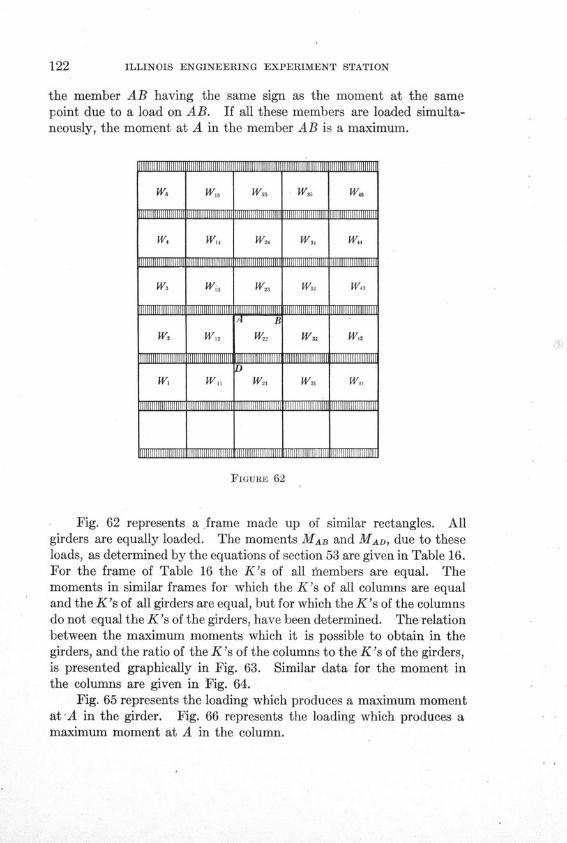
ILLINOIS ENGINEERING EXPERIMENT STATION
the member AB having the same sign as the moment at the samepoint due to a load on AB. If all these members are loaded simulta-neously, the moment at A in the member AB is a maximum.
w6
w3
W2
w,
WIs
Wi
W1 2
Wit
W,5
W22
W21
I liillH »illi
W4
W43
W4
w »1111111
FIGURE 62
Fig. 62 represents a frame made up of similar rectangles. Allgirders are equally loaded. The moments MAB and MAD, due to theseloads, as determined by the equations of section 53 are given in Table 16.For the frame of Table 16 the K's of all ihembers are equal. Themoments in similar frames for which the K's of all columns are equaland the K's of all girders are equal, but for which the K's of the columnsdo not equal the K's of the girders, have been determined. The relationbetween the maximum moments which it is possible to obtain in thegirders, and the ratio of the K's of the columns to the K's of the girders,is presented graphically in Fig. 63. Similar data for the moment inthe columns are given in Fig. 64.
Fig. 65 represents the loading which produces a maximum momentat*A in the girder. Fig. 66 represents the loading which produces amaximum moment at A in the column.
lilliillH Illl lKi
Ws
Wu
Willail
Was
ifliliillfilllJim l
mmlllWW IIII~~l
Al
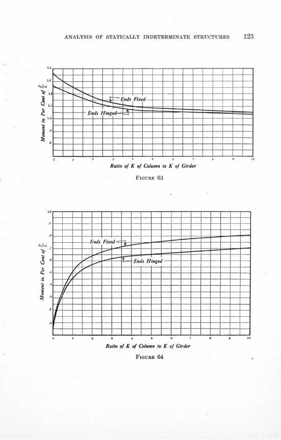
ANALYSIS OF STATICALLY INDETERMINATE STRUCTURES
i
S 2 3 4 5 a 7 - #
Ratio of K of Column to K of Girder
FIGURE 64
y..4
..L4
12
2 3 4 57 8
Ends Fixed- - - -- - - -
Ens H- -n -- - Ends Hinged
*------ ^ - -". -Ends Hinged----------------------.~.. ^ ^ ~Z ~Z'L 'LLZ~Z^ LI ~.Z
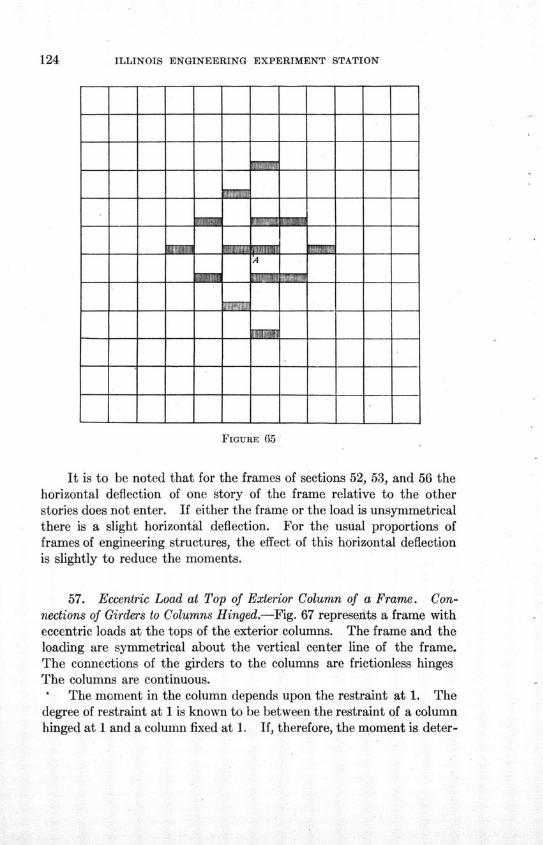
ILLINOIS ENGINEERING EXPERIMENT STATION
FIGURE 65
It is to be noted that for the frames of sections 52, 53, and 56 thehorizontal deflection of one story of the frame relative to the otherstories does not enter. If either the frame or the load is unsymmetricalthere is a slight horizontal deflection. For the usual proportions offrames of engineering structures, the effect of this horizontal deflectionis slightly to reduce the moments.
57. Eccentric Load at Top of Exterior Column of a Frame. Con-nections of Girders to Columns Hinged.-Fig. 67 represents a frame witheccentric loads at the tops of the exterior columns. The frame and theloading are symmetrical about the vertical center line of the frame.The connections of the girders to the columns are frictionless hingesThe columns are continuous.
The moment in the column depends upon the restraint at 1. Thedegree of restraint at 1 is known to be between the restraint of a columnhinged at 1 and a column fixed at 1. If, therefore, the moment is deter-
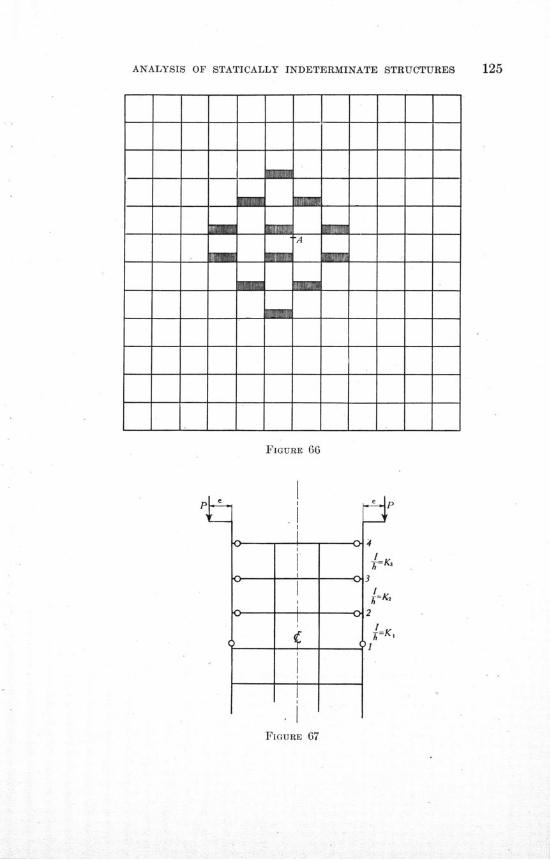
ANALYSIS OF STATICALLY INDETERMINATE STRUCTURES
Pt
FIGURE 66
UE 67
FIGURE 07
4
I
3
2
I=K,
'1
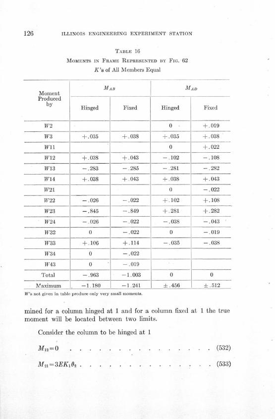
ILLINOIS ENGINEERING EXPERIMENT STATION
TABLE 16
MOMENTS IN FRAME REPRESENTED BY FIG. 62
K's of All Members Equal
MomentProduced
by
W2
W3
Wil
W12
W13
W14
W21
W22
W23
W24
W32
W33
W34
W43
Total
Maximum
MAD
Hinged
+.035
+.038
-. 283
+.038
-. 026
-. 845
-. 026
0
+.106
0
0
-. 963
-1.180
Fixed
+.038
+.043
-. 285
4+.043
-. 022
-. 849
-. 022
-. 022
+.114
-. 022
-. 019
-1.003
-1.241
Hinged
0
+.035
0
-. 102
-. 281
+.038
0
+.102
+ .281
-. 038
0
-. 035
0
±.456
Fixed
+.019
+.038
+.022
-. 108
-. 282
+.043
-. 022
+.108
+.282
-. 043
-. 019
-. 038
0
± .512
W's not given in table produce only very small moments.
mined for a column hinged at 1 and for a column fixed at 1 the truemoment will be located between two limits.
Consider the column to be hinged at 1
M 12=0 . . . . . . . . . . . . . . (532)
M 21= 3EK1 02 . . . . (533)
ANALYSIS OF STATICALLY INDETERMINATE STRUCTURES
From equation 501, section 52,
12=4EK2. 3 3 K ) . . . . . . . . . . (534)
M 3 4 = -M 3 2 = -4EK2 0 3 3K 2+ 3K '=2EK(• 203+04) . (535)(4K2+ 3K)
M143= 2EK3(204 +0) . . . . . . . . . . . (536)
3K±+3K 2Let N 2 = 4 3K 4
3K,+4K2
From equations 534 and 535
M43 = 4EK3 4 ......... (537)
Also
M43 = Pe .... . ......... . . (538)
From equations 537 and 538
P- P e N 2K 2+4K34EK, N 2K 2+3K * . . . . . . . . . . . (539)
Eliminating 03 from equations 535 and 536 gives
M 34=-6EK3 04+2Pe . . . . . . . . . . . (540)
Substituting the value of 04 from equation 539 gives
Pe N 2K 2M34= P N 2K 2 ± 3K . . . . . . . . (541)
M 32 = -M 34 . . . . . . . . .. . . . (542)
From the equations of Table 1
M32= 2EK 2(203 +02) . . . . . . . . . . (543)
M 23=2EK2(20 2 + 0) . . . . . . . . . . . (544)
ILLINOIS ENGINEERING EXPERIMENT STATION
Eliminating 08 gives
2M 23-M 32 =6EK2 0 2 . ...... . . . .. (545)
From equations 533, 545, and 542, and since M21 -M23
K1M23=- K, M3 . . . . . . . . . . (546)2(Ki +K2)
If, therefore, the column is hinged at 1
M 43=Pe . . . . . . . . . . . . . . (538)
Pe K,M 34 = - M N 2 . . (541)2 LN2K2+3K ..
KIM21 = -M23= , MA34 . . . . . . . (546)
4K1+3KA
If the column is fixed at 1, letting N '2 represent 4 4K 3K 24K 1+4K 2
M 43=Pe . . . . . . . . . . . . . . . (547)
Pe N'K,2 N' 2K 2+3K3
2K1M21=-AM23K= -32 M34 . . . . . . . . (549)
From a comparison of equations 538, 541, and 546 with 547, 548,and 549 it is apparent that the restraint at 1 does not materially affectthe moments at 2 and 3. For purposes of design the moments as givenby either equations 538, 541, and 546 or by equations 547, 548, and549 are satisfactory. Moreover the average of the moments obtainedby 538, 541, and 546, and 547, 548, and 549 approximate very closelythe true moments.
If the K's are all equal, a condition often approximated in practice:For column hinged at 1
M4a=Pe . (550)
ANALYSIS OF STATICALLY INDETERMINATE STRUCTURES
M 34=-M 32 =- Pe=0.266Pe . . . . . . . . (551)15
M 21 =-M 23 = - Pe = 0.067Pe . . . . . . . . (552)15
For column fixed at 1
M 4 = Pe ............. . . (553)
7M 34 = -M 32 = - Pe= 0.269 Pe . . . . . . . . (554)
26
M2= M23 = -- Pe= 0.077 Pe . . . . . . . . (555)
It is to be noted that the frame considered is symmetrical about avertical center line and is symmetrically loaded. If there is a load onthe right-hand column only, the moments in that column will beslightly smaller than the moments given by the equation, and theother columns will be subjected to a small moment. The error in themoment in the loaded column and the neglected moment in the othercolumns increase as the ratio of the stiffness of the loaded column tothe combined stiffness of the other columns increase. Although theyhave not been able to establish this statement mathematically, it isthe opinion of the writers that if the equations of this section areapplied to a frame that is either unsymmetrical or unsymmetricallyloaded, the error due to the horizontal deflection of the frame is negligiblefor purposes of design.
58. Eccentric Load at Top of Exterior Column of a Frame. Con-nections of Girders to Columns Rigid.-Fig. 68 represents a frame witheccentric loads at the tops of the exterior columns. The frame and theloading are symmetrical about the vertical center line of the frame.The connections of the girders to the columns are rigid.
An exact determination of the moments in the frame is practicallyimpossible. From previous similar work, however, it is known that ofthe moments produced by P on the right-hand side of the frame, onlythe moments at A, B, C, and F are large enough to be considered in thedesign of the frame. Furthermore, from previous work it is knownthat the moments at A, B, C, and F are practically independent of thedegree of restraint at J, K, G, H, and D.
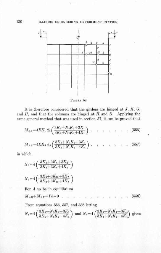
ILLINOIS ENGINEERING EXPERIMENT STATION
FIGURE 68
It is therefore considered that the girders are hinged at J, K, G,and H, and that the columns are hinged at H and D. Applying thesame general method that was used in section 57, it can be proved that
MAB = 4EK A ( 3KX+N2K2+3KX (556)
3Ka +N2K2+4KI . . ... . .
MAF = 4EK4 OA ( 3K N7K7 3K4 .(557)3K,+N7K-+4K4 . ..... .
in which
N2=4( 3K3+3K6+3K22 3K3+3K6+4K2
N7=4( 3K8+3K±o+3K 7
8 \ 3K 8+3KXo+4K 7 )
For A to be in equilibrium
MAB+MAF-Pe=O . ............ (558)
From equations 556, 557, and 558 letting=4, / 3K5+N 2K 2+3K 1 3K 9+N 7K 7+3K 4 gives
N=( 4 KnKd N)=4K^^ 4 gives
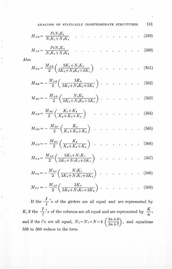
ANALYSIS OF STATICALLY INDETERMINATE STRUCTURES 131
MA- PeNKi (559)A N1Ki+N 4K 4 . . . . . . . . . . .
MA - PeN4K 4MA.F 1K.+N 4K 4 . . . . . . . . . . . . (560)
Also
MB MAB ( 3Ks+NsK2 (561)2 3K 5+N 2K 2+3K 1 . . . . (561)
BG - A- . . . . . . (562)2 3K 5+N 2K 2+3K 1 ........
MAc=c-- MAB ( (563)
MCB- 3fBc K . .. ..... (564)
MCH - BC K 6 ) ........ (565)2=(K3+K6+K2) . . . . . . . .
MCD- - MBC ( K ) (566)
A2 3K,+N7K7 3K 4 . .......
MG MA (N 7K 7 ......... (568)
2-A,=) . . . . . . . . (566)
M+ = - MAP ( 3K (567)2 3K 9+NK,+3K4 ........
M A. Yg (568)
M„j MAAF 3K9 K,M =-- 7 3K+^AK+3Kj ] ....... (569)
If the -- s of the girders are all equal and are represented by
I, KK, if the s of the columns are all equal and are represented by -,
I n
and if the I's are all equal, N 2=N 7=N=4 (3n , and equations559 to 569 reduce to the form+
559 to 569 reduce to the form
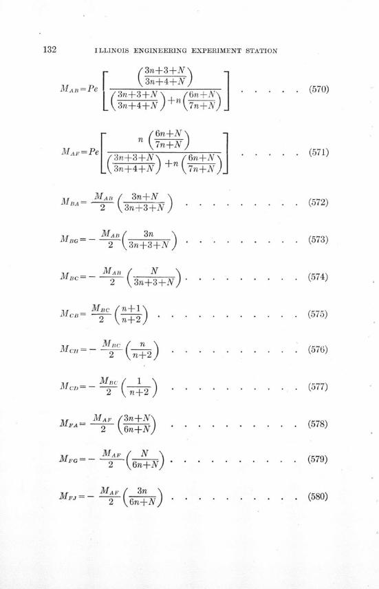
ILLINOIS ENGINEERING EXPERIMENT STATION
F ( 3n+3+N) -13n4n+4+N}
MAB =Pe ( 3n+3+ N (7n±N) (570)
3n+4+N ) 7n+N)
r- 6n+N-\
MAF = Pe 3n+3+N N 6n+N . . (571)
(3n+4+N) +n 7n+N
M MA 3n±NM3A=M- 3n+N (572)2 3n+3+N.........
MABn (3n
MBc= -- ( . . . . . . . . . (574)2 3n+3+N " .......
2 ( n +327Mc = - • n-( ) . . . . . . . . . . (575)
Mcn=- { M. . . . . . . ..... (578)
MC ==- M"-n 1 . . . . . . . . . . (577)
AMAF 3n+N2 6- . . ... . . . . .. . (578)
2FG= -- 2 6n+N . . . . . . . . . (579)
MF == -- M . . . . . . .... (580)2 6n-EN
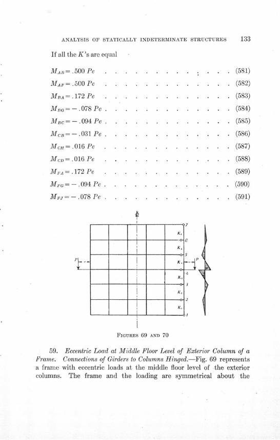
ANALYSIS OF STATICALLY INDETERMINATE STRUCTURES
If all the K's are equal
MAB = .500 Pe
MAF=.500 Pe
MBA= .172 Pe
MBG= -. 078 Pe
MBac= -. 094 Pe
McB =-.031Pe
Mc=.016 Pe .
MCD=.016 Pe
MFA=.172 Pe .
MFG= -. 094Pe .
MF = -. 078 Pe .
Pp.
. .. . . (581)
. . . . . (582)
. . . . . (583)
. . . . (584)
. . . . . (585)
. . . . . (586)
. . . . . (587)
. . . . (588)
. . . . . (589)
. . . . (590)
. . . . . (591)
7- K,K,
K,K,
±-K
-K
±2-
K.
K,
K,
4
2
P4
FIGURES 69 AND 70
59. Eccentric Load at Middle Floor Level of Exterior Column of aFrame. Connections of Girders to Columns Hinged.-Fig. 69 representsa frame with eccentric loads at the middle floor level of the exteriorcolumns. The frame and the loading are symmetrical about the
L

ILLINOIS ENGINEERING EXPERIMENT STATION
vertical center line of the frame. The connections of the girders to thecolumns are hinged.
The moments are practically independent of the degree of restraintat 1 and 7. The column is therefore assumed to be hinged at 1 and 7.
-M 43-M 45 +Pe=0 ....... . . . . (592)
( N2K2+4KsM43= Pe K NK+3K (593)A143 = Pe N 2K 2+3K 3 +K N5 +3K 4
N 2K2+4K3 Ns+4K4
M 4 5=Pe-M 4 3 . . . . . . . . . . . . (594)
M 34= -Ma M43 N 2K 2 .(595)M4 =-M3= 2 NIK2+3K
Mb4=--M,6= NM14 NsK, (596)2 NsK5+3K4 .....
M 2 1 = -M 2 3 = M 4 . . . . . . . (597)
M67=- M65=M54[ K 6 1= -Me=M 2(K+K 6 ) . . .. . . . .. (598)
In these equations
N2= 4 (3K+3K23Ki+4K2
N=4 (3K6+3K){" 3K6+4K5
When all K's are equal
M 43=M 45==- Pe= 0.5000 Pe . . . . . . . . . (599)2
M 34=M 4 = 2 Pe=O0.1333 Pe . . . . . . . . . (600)15
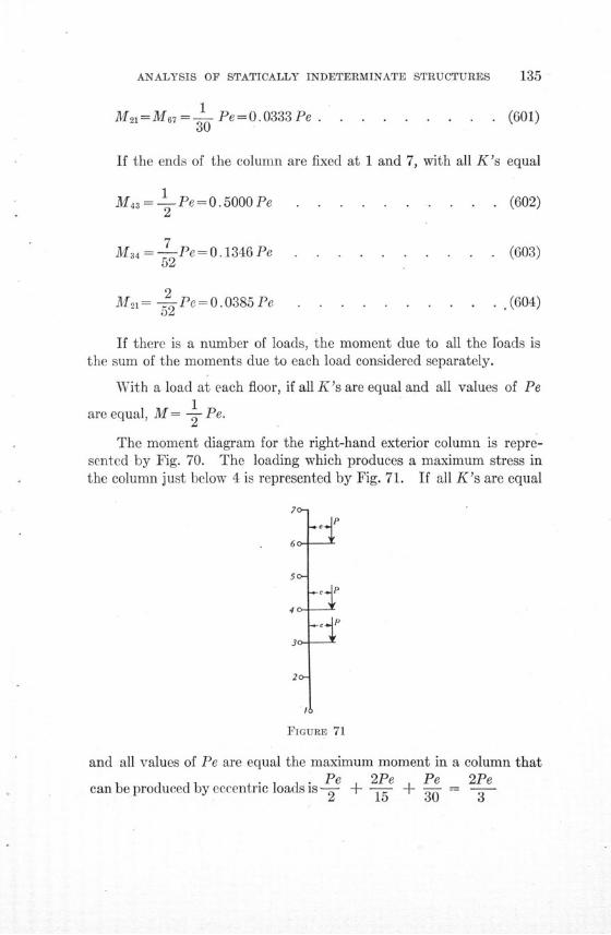
ANALYSIS OF STATICALLY INDETERMINATE STRUCTURES
M 2 = M 67 =- Pe= 0.0333 Pe .30
. (601)
If the ends of the column are fixed at 1 and 7, with all K's equal
M43 = Pe= 0.5000 Pe2
M 34 = - Pe= 0.1346 Pe52
M21-= 2 Pe= 0.0385 Pe
-52
. (602)
. (603)
. (604)
If there is a number of loads, the moment due to all the roads isthe sum of the moments due to each load considered separately.
With a load at each floor, if all K's are equal and all values of Pe1
are equal, M = - Pe.
The moment diagram for the right-hand exterior column is repre-sented by Fig. 70. The loading which produces a maximum stress inthe column just below 4 is represented by Fig. 71. If all K's are equal
/7o-
60-
50-
I P
ItFIGURE 71
and all values of Pe are equal the maximum moment in a column that. P 2Pe Pe 2Pe
can be produced by eccentric loads is -L- +4- - + - -=
/o-6o-5o- P:I
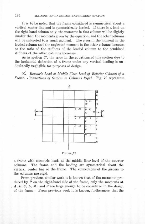
ILLINOIS ENGINEERING EXPERIMENT STATION
It is to be noted that the frame considered is symmetrical about avertical center line and is symmetrically loaded. If there is a load onthe right-hand column only, the moments in that column will be slightlysmaller than the moments given by the equation, and the other columnswill be subjected to a small moment. The error in the moment in theloaded column and the neglected moment in the other columns increaseas the ratio of the stiffness of the loaded column to the combinedstiffness of the other columns increases.
As in section 57, the error in the equations of this section due tothe horizontal deflection of a frame under any vertical loading is un-doubtedly negligible for purposes of design.
60. Eccentric Load at Middle Floor Level of Exterior Column of aFrame. . Connections of Girders to Columns Rigid.-Fig. 72 represents
FIGURE-72
a frame with eccentric loads at the middle floor level of the exteriorcolumns. The frame and the loading are symmetrical about thevertical center line of the frame. The connections of the girders tothe columns are rigid.
From previous similar work it is known that of the moments pro-duced by P on the right-hand side of the frame, only the moments atA, B, C, L, M, and F are large enough to be considered in the designof the frame. From previous work it is known, furthermore, that the
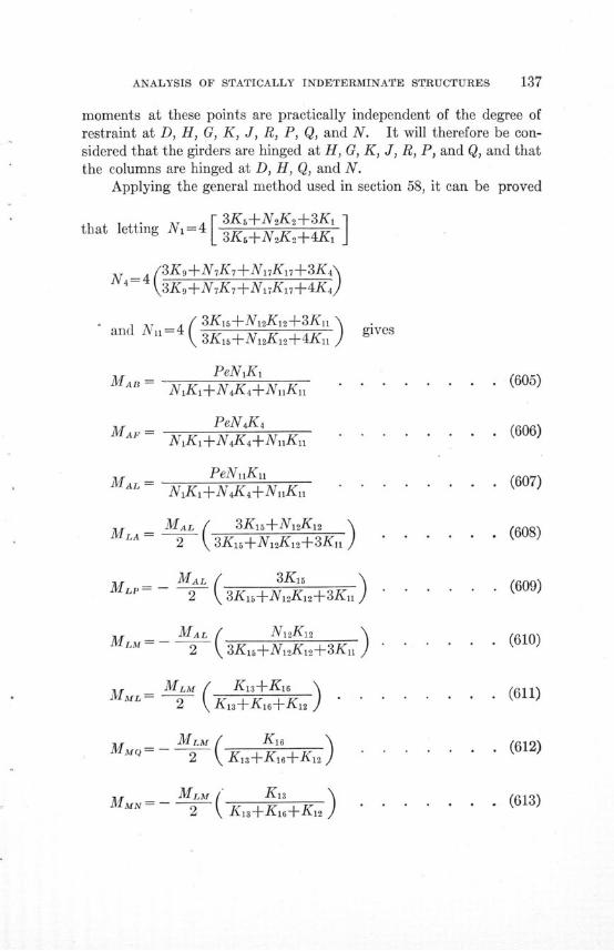
ANALYSIS OF STATICALLY INDETERMINATE STRUCTURES
moments at these points are practically independent of the degree ofrestraint at D, H, G, K, J, R, P, Q, and N. It will therefore be con-sidered that the girders are hinged at H, G, K, J, R, P, and Q, and thatthe columns are hinged at D, H, Q, and N.
Applying the general method used in section 58, it can be proved
that letting N=4 [ 3K+N2K2+3K1]
N4=4 3K,+N7K7+N17K17+3K4"4 3K,+NK7+N ,K7+4K,}
and N,,=4 ( 3Ki+N12K12+3KnS3K1iN^+2KI+4Kn
S= PeNK,SNiKi+N 4K 4+NnKn "
MA = PeN4K4M= NIK1 +N 4K 4+N1Ki
PeNuiKuiML= N1K+N 4K 4+NnK, "
MLA = MAL ( 3K 15+N 12K1 22 3K 5I+Ng2Kl2+3Kn}
M = MAL ( 3K15MLP 2 3Kis+N 1 2K 12+3K 11
M MA L ( N12K2
MM - 2 3K15+N12K12+3Kn11
MML MLM (K1is+Ki16
2 K 13+K 16+K 12 )
M= - M L M ( K u 6M^-2 Ki3+K,6+Kk)
gives
. . . . (605)
. . . . (606)
. . . . (607)
. . . . (608)
. (609)
. . . (610)
* (611)
. (612)
(613)
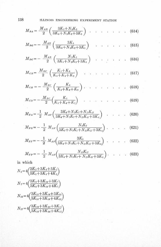
ILLINOIS ENGINEERING EXPERIMENT STATION
MBA MAB ( 3Ks+NK2
MBA= -Ma ( 3KM
2 3K6+N2K2+3K, "
MBc= MAB ( N2 K2,
2 - 3K 5+N 2K 2+3K,
MCB Mc K(3+KS6
2 K(+K6+K2Mc= M
Bc K
2 K3+K•+K
FA 1 3K+N4Kr+Nl7K,MF = - Ma 3K 9+N 7K 7+N 7K 7+3K 4 J
S1 NK 7MFG 2 = -3K,+NK,+Nl7K7+3K4 "
M 1 M / 3K9 \- 3K9+N 7K7+N 7 K 7+3K 4)
Mp - 1 MAF N17K17M-- 3K9 + NK+NK 17 + 3K 4
in which
N2 =(3K3+3K6+3K2,3K3+3K6+4K2)
N 4 (3Ks+3Kxo+3K,(3K8+3K,1+4K7
N 4 /3K13+3Ký6+3K12.(3K13+3K16-4K12)
N7= 4(3Ki8+3K20+3K17ýN •3K32s+3K2o+4K,7
N__• • 7
(614)
(615)
(616)
. . (617)
(618)
(619)
(620)
(621)
(622)
(623)
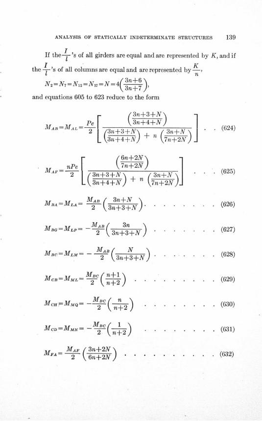
ANALYSIS OF STATICALLY INDETERMINATE STRUCTURES
IIf the- 's of all girders are equal and are represented by K, and if
I Kthe -'s of all columns are equal and are represented by -,
I n
and equations 605 to 623 reduce to the formN
and equations 605 to 623 reduce to the form
/3n-
MAB=MAL -Pe2 3n+3+N'
3n+4+N)
t- -IV
+4+N)
+ 3n+ N
(7n+2N ]
(6n+2N -
SnPe \7n+2N2 = 3n+3+N+ ( 3n+N
3n+4+N} + 7n+2N )
MAB ( 3n+N2 3n+3+N"
_MAB( 3n2 ( 3n+3+N )
MJn N N2 3n+3+N
MAc2 n+1
MCB=MML= -
M" MMQ= - MBC ( n \Mc^M^-- n+2^
MCD= MMN= -M( 1
. . . . (626)
. . (627)
. . . . (628)
. . . . (629)
. . (630)
. . (631)
. . . . . (632)
. . (624)
. (625)
MBA= MLA=
MBG = MLP =
MBA = MLM =
MA =MAF (3n+2N2 6n+2N
I
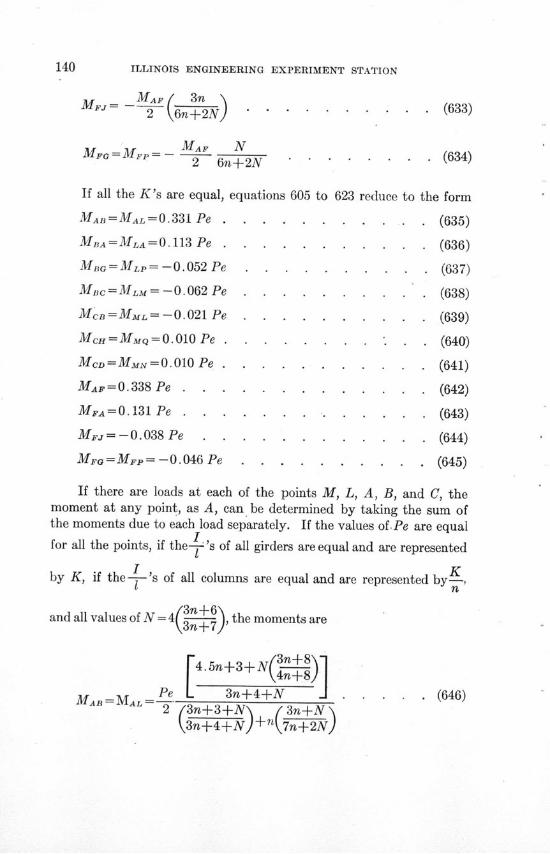
140 ILLINOIS ENGINEERING EXPERIMENT STATION
MFJ= MAF / 3n (2 6n+2N) . ......... .(633)
MF = M.P - MAF N2 6n+2N...... (634)
If all the K's are equal, equations 605 to 623 reduce to the form
MAB=MAL = 0.331 Pe . . . . . . . . . . . (635)
MABA =MLA=0.113Pe ....... . . . . (636)
MBG=MLp= -0.052 Pe . . . . . . .... . (637)
MBc=MLM= -0.062 Pe . . . . . . . . .. (638)
McB=MML=-0.021Pe ....... . . . (639)
McH=MMQ=0.010Pe .. . . . . . . . (640)
McD=MMN=0.010Pe ........... . (641)
MAF=0.338Pe ........... . . (642)
MA = 0.131 Pe . . . . . . . . . . . . . (643)
Mj = - 0.038Pe ........ . . . . (644)
MFG=MFP= -0.046 Pe . . . . . . . . . . (645)
If there are loads at each of the points M, L, A, B, and C, themoment at any point, as A, can be determined by taking the sum ofthe moments due to each load separately. If the values of.Pe are equal
Ifor all the points, if the-'s of all girders are equal and are represented
by K, if the- 's of all columns are equal and are represented by K
1 n
and all values of N = 4(3 , the moments are3n+7
4.5n+3+N 4n+8
MA = MA e 3 4+N . . . (646)2 (3n+3+N\ n 3n+N
3n+4+NJ n 7n+2NJ
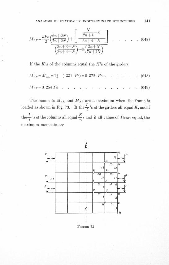
ANALYSIS OF STATICALLY INDETERMINATE STRUCTURES 141
N -3
nPe 6n+2N+ 2n+4 3
MAF--~ 7n+2N 3n+4+N . . . . . (647)
(3n+3+N\ /3n+N3n+4+N) 7n+2N)
If the K's of the columns equal the K's of the girders
MAn=AMAL=1- (.331 Pe)=0.372 Pe . . . . . . (648)
MA = 0.254Pe . . . . . . . . . . . . .. (649)
The moments MAL and MAB are a maximum when the frame is
loaded as shown in Fig. 73. If the- 's of the girders all equal K, and if
I Kthe- 's of the columns all equal - and if all values of Pe are equal, the
1 n
maximum moments are
FIGURE 73
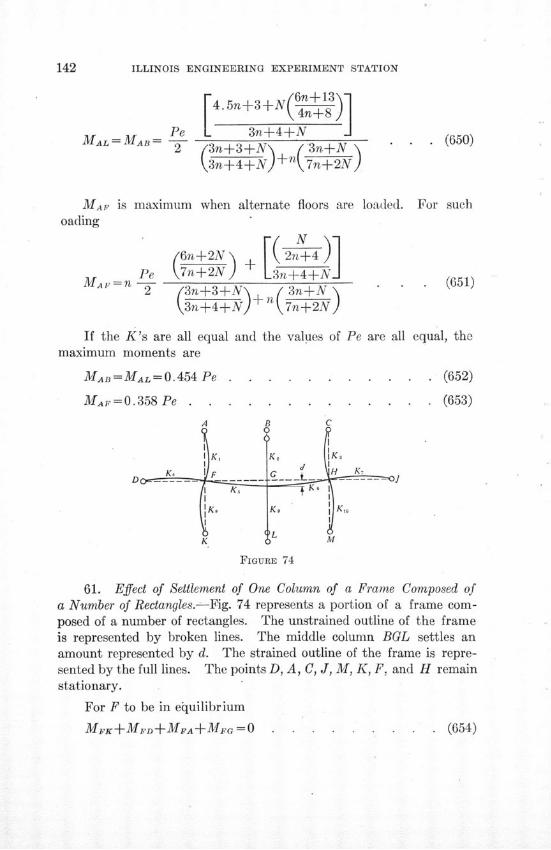
ILLINOIS ENGINEERING EXPERIMENT STATION
PeMAL = MAB = --
2
4.5n+3+N(n+13]
3n+4+N3n+3+ 3n_+N
(3n+4)+N + n 7n+2N
MAF is maximum when alternate floors are loaded. For suchoading
PeMAr=n Pe
2
( N \N(6n +2N 2n+4 )7n+2N + 3n+4+N( 3n+3+N+ / 3n+N\3n+4+N) 7n+2N)
(651)
If the K's are all equal and the values of Pemaximum moments are
MAB =MAL = 0.454 Pe . . . . . . .
MAF=0.358 Pe . . . . . . . . .
are all equal, the
. (652)
. (653)
C
I K,
SK,
K
K, KM
M
FIGURE 74
61. Effect of Settlement of One Column of a Frame Composed ofa Number of Rectangles.-Fig. 74 represents a portion of a frame com-posed of a number of rectangles. The unstrained outline of the frameis represented by broken lines. The middle column BGL settles anamount represented by d. The strained outline of the frame is repre-sented by the full lines. The points D, A, C, J, M, K, F, and H remainstationary.
For F to be in equilibrium
MFK+MvD+MFA+MFGO . .
. (650)
. . . (654)
A
ANALYSIS OF STATICALLY INDETERMINATE STRUCTURES
Substituting the values of the M's as given by the equations ofTable 1 gives
3EO( Ks+K 4+K) +2EK(2+ O-3 )=0 . . . (655)
or
d6K 5 - -2K 5
0G0,= . . . . . . . . . . . (656)
3K 4+ 3K 1+3K 8 + 4K 5
MGF =2EK(20G+ F-3- ) . . . . . . . . . (657)is
Substituting the value of O9 from equation 656 in equation 657 gives
MG F K40G /'3K 4+3Ki+3Ks+3K 5\
IG ( 3K 4+ 3K +3K 8+4K 5)
6d 3K 4+3Ki+3K 8+2K 5\ 65±K)j.. .......... (658)
1, (3K4+3Ki+3K8+4K J . . . . . . . .
Similarly for the right-hand portion of the structure
M, = EK6 4 •F 3K 7+3K 3 +3Ko+3K 6 ,MG E ( 3K,+3K3 +3Ko+4K6)
6d 3K,+3Ka+3Ko+2K\ (659)16 \3K7+3K 3+3Ko+4K 6)] . . ...... (659)
MGB=3EK29o . ........... . (660)
MGL=3EK9, 0a . . . . . . . . . . . . . (661)
For G to be in equilibrium
MGF+MCH+MGB+MGL =0 . . . (662)
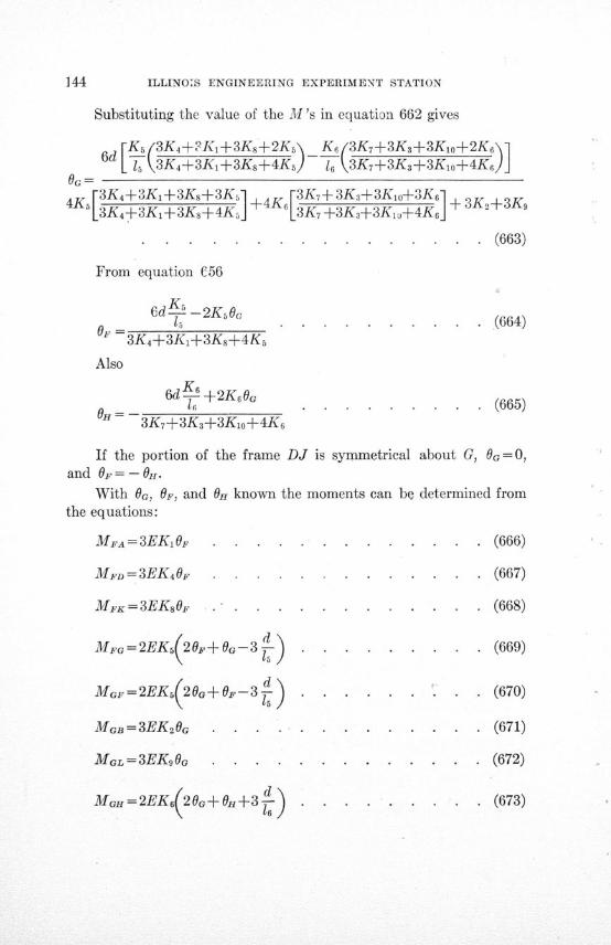
144 ILLINOIS ENGINEERING EXPERIMENT STATION
Substituting the value of the M's in equation 662 gives
6d[Ks 3K4+?Ki+3Ks+2Ks K 6 3K,+3K3 +3K 1 o+2K6e\6d [ (3K4+3Ki+3Ks+4K. 1-, 3K 7+3K+3Ko+4K 6
0G4. [3K4+3K,+3Ks+3K 5 3K. r3K7+3K3-+3Kio+-3K6] 3K4 Ks[3 ±K\ + 4 K. . . . . . . . .+ 31 2+ 3K
13K 4+3K.+3K 8 +4K 5 . 3K 7 +3Ks+3K 1.+4K 6
............................. . .. (663)
From equation C56
6dK -2K 5OGOF =5O 3K 4+3Ki+3K8+4K 5
Also
. (664)
6d L6 +2K60G
. . =.l . . . . . . . . . . (665)3K 7+3K 3+3K1o+4K
6
If the portion of the frame DJ is symmetrical about G, 0o= 0,and OF= - OH.
With 0G, OF, and O0 known the moments can be determined from
the equations:
MFA= 3EK0 . . . .. . . . . . . . (666)
MD = 3EK4 . . .. ...... . . . (667)
MFK=3EKs8 O ... . . . . . . . . . . (668)
MFG= 2EK 5(2OF+OG-3 ) .. . . . . . . . (669)
MoF=2EK(20Go+OF-3 .. . . . . . . .. (670)
MGB=3EK2OG . . . . . . . . . . .. . (671)
MGL = 3EK90G . ........... . (672)
MGH= 2EK 6(2G+OH+3\ 16 )
(673)
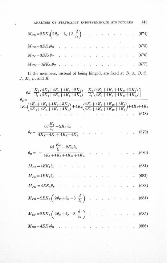
ANALYSIS OF STATICALLY INDETERMINATE STRUCTURES
MHG=2EK 6 20H+6G+3 ) . . . . . . . . . (674)
Muc= 3EK3 OH .............. (675)
MH. =3EK7OH . ............. (676)
MaM =3EKloOH ..... ....... . . (677)
If the members, instead of being hinged, are fixed at D, A, B, C,J, M, L, and K
[Ks 4K4+4Ki+4KA8+2K5 Kg 4K,7+4K3+4K2o+2Kg61d \4K4+4K,+4Ks+4K] 16 4K,+4K3+4KJo+4KJ
OG =
4, "4K4+4Ki+4Ks+3K , + 4 4K7+4K3+4Ko+3K6\, , ,.4KS4K4+4K+4K+4Kxj 4K7+4K3+4K±o+4K6 24
. . . . . . . . . . . . . . . . (678)
6d K -2Ks OG
66
OF = 15 (679)
6d K +2K6 G
O=- . .. . . . (680)4K,+4K3+4Kio+4K6 . . . . . . . .
MFA=4EKi OF .... . . . . . . . (681)
MFD = 4EK4 . . ........... (682)
MFK = 4EK8sO . . . . . . . . . ... (683)
MFG=2EKs(20F+OG-3 -- ) . . . . . . .. (684)
MoG=2EKs( 20G+OF-3-) . . . . . . . . (685)
MGB=4EK26G . (686)
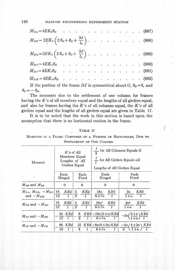
ILLINOIS ENGINEERING EXPERIMENT STATION
MGL= 4EK9OG . . . . .
MGH= 2EK, 2 G+OH+ 3 )
MHG=2EK (20H+OG+ * .
MHc= 4EK0H . . . . .
MHJ = 4EK7 OH . . . . .
MHM = 4EKLo0H .. . . ..
. . . . . (687)
S(688)
S(689)
. (690)
. (691)
. (692)
If the portion of the frame DJ is symmetrical about G, 0 G = 0, andOF = - OH.
The moments due to the settlement of one column for frameshaving the K's of all members equal and the lengths of all girders equal,and also for frames having the K's of all columns equal, the K's of allgirders equal and the lengths of all girders equal are given in Table 17.
It is to be noted that the work in this section is based upon theassumption that there is no horizontal motion in the frame.
TABLE 17
MOMENTS IN A FRAME COMPOSED OF A NUMBER OF RECTANGLES, DUE TO
SETTLEMENT OF ONE COLUMN
K's of A - for All Columns Equals K
Members Equal f
Moment Lengths of All - for All Girders Equals nK
Girders Equal Lengths of All Girders Equal
Ends Ends Ends EndsHinged Fixed Hinged Fixed
MaB and MOL 0 0 0 0
MFA, MFK, -MHc, 18 KEd 3 KEd 18n KEd 3n KEdand -MHM 13 1 2 -T 6+7n 1 T+n I
MFD and -MHJ 18 KEd 3 KEd 18n KEd 3n' KEd13 1 2 1 6+7n 1 1+n I
54 KEd 9 KEd -18n(2+n)KEd 3n(2+n\KEdand -MH 13 - 2 1 6+7n 1 - 1 +n -
MGF and -MoH 66 KEd 21 KEd -6n(6+5n)KEd -3n(4+3n\ KEd13 I 4 1 6+7n 1 2 \l+n l
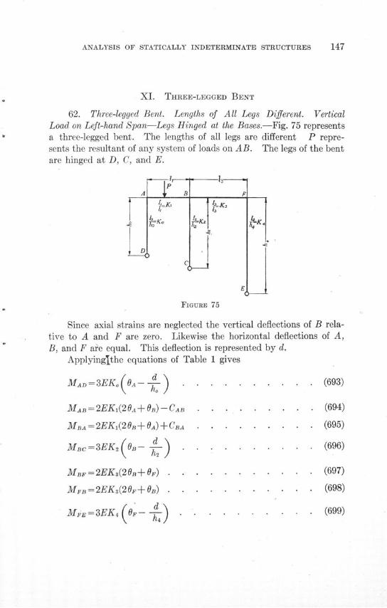
ANALYSIS OF STATICALLY INDETERMINATE STRUCTURES
XI. THREE-LEGGED BENT
62. Three-legged Bent. Lengths of All Legs Different. VerticalLoad on Left-hand Span-Legs Hinged at the Bases.-Fig. 75 representsa three-legged bent. The lengths of all legs are different P repre-sents the resultant of any system of loads on AB. The legs of the bentare hinged at D, C, and E.
FIGURE 75
Since axial strains are neglected the vertical deflections of B rela-tive to A and F are zero. Likewise the horizontal deflections of A,B, and F are equal. This deflection is represented by d.
Applyinglthe equations of Table 1 gives
MAD=3EK( OA---) . . . . . . . .. .. (693)
MAB=2EKl(20A+OB)-CAB . . . . . . . .. . (694)
MBA = 2EK1 (2 B + A) CBA . . . . . . . . . (695)
MBC=3EK,(OB- - .) . . . . . . .. (696)
MBF = 2EK3(2B+F) . . ........ ... (697)
MFB=2EK3(20+ ) . . .. ....... ... (698)
MFE= 3EK4 O. . . .. . . . . . . (699)
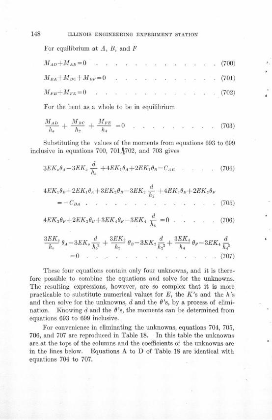
148 ILLINOIS ENGINEERING EXPERIMENT STATION
For equilibrium at A, B, and F
MAD +MAB = 0 ....... . . . . . . (700)
MBA+MBC+MB= . . . . .. . . . . (701)
MFB+MFE=O . . . . . . . . . . . . . (702)
For the bent as a whole to be in equilibrium
MAD MBC MFEh + A-+ +0 . . . . . . . . . (703)ho h, h4
Substituting the values of the moments from equations 693 to 699inclusive in equations 700, 701,1702, and 703 gives
d3EK OA-3EKo + 4EKIOA+2EKB = CAn . . . . (704)
d4EKi B + 2EK1iA + 3EK2 O - 3EK 2 -d- 4EK30B+2EK,0.
=--CBA . . . . . . . . . . . . . . (705)
d4EK3Oe+2EKaOB+3EK4OF-3EK =0 . . . .. (706)
3EKo OA3EK d 3EK 2 d - 34 dho A-3EK -- + 2 OB-3EKA2 + A OF -3EK 4 -
= 0 . . . . . . . . . . . . . (707)
These four equations contain only four unknowns, and it is there-fore possible to combine the equations and solve for the unknowns.The resulting expressions, however, are so complex that it is morepracticable to substitute numerical values for E, the K's and the h'sand then solve for the unknowns, d and the O's, by a process of elimi-nation. Knowing d and the O's, the moments can be determined fromequations 693 to 699 inclusive.
For convenience in eliminating the unknowns, equations 704, 705,706, and 707 are reproduced in Table 18. In this table the unknownsare at the tops of the columns and the coefficients of the unknowns arein the lines below. Equations A to D of Table 18 are identical withequations 704 to 707.
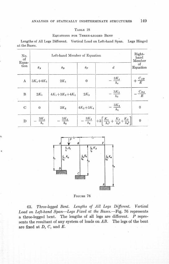
ANALYSIS OF STATICALLY INDETERMINATE STRUCTURES
TABLE 18
EQUATIONS FOR THREE-LEGGED BENT
Lengths of All Legs Different. Vertical Load on Left-hand Span.at the Bases.
Left-hand Member of Equation
OA
3K,+4K1
2Ki
0
3Koh.
OB
2K 1
4K 1+3K2+4K 3
2K 3
3K 2
h2
A
Op
0
2K 3
4K 3 +3K 4
3K 4
h4
K B.
c
d
3Ko
ho
3K 2h2
3K 4
h4
I3 h-2 -- 2 -2 -h42
noU
Legs Hinged
Right-hand
Memberof
Equation
CAB+ E
CBAE
0
0
F
FIGURE 76
63. Three-legged Bent. Lengths of All Legs Different. VerticalLoad on Left-hand Span-Legs Fixed at the Bases.-Fig. 76 represents
a three-legged bent. The lengths of all legs are different. P repre-
sents the resultant of any system of loads on AB. The legs of the bent
are fixed at D, C, and E.
No.of
Equa-tion
A
B
C
I-
I
I r
WWA
ILLINOIS ENGINEERING EXPERIMENT STATION
From the equations of Table 1
MAD=2EKo(20A-3 ) ......... (708)
MAn=2EKi(2OA+OB)-CAB . . . . . . . . . (709)
MBA=2EKi(20B+0A)+CBA . . . . . . . . . (710)
MBc=2EK2•20B-3--d) . ........ .. (711)
MF =2EK(20B+OF) . . . . . . . . . .. (712)
MFB=2EK3(20F+0) . ........... (713)
MFE= 2EK( 20F-3 d ) . . . . . . . . . (714)
MDA = 2EKo( OA-3 ) d .......... (715)
McB=2EK2 0(B-3-) . ...... . . . (716)
MEF=2EK4 (OF -- 3-) . . ....... ... (717)
For equilibrium at A, B, and F, equations 700, 701, and 702 areapplicable.
For the bent as a whole to be in equilibrium
MAD+MDA + MBC+MCB + MFEMEF =-0 . . . . (718)ho h2 h4
Substituting the values of the moments from equations 708 to 717
in equations 700, 701, 702, and 718 gives the equations of Table 19.
64. Three-legged Bent. Lengths of All Legs Different. Any System
of Loads.-No matter what system of loads is applied to the three-
legged bents of Figs. 75 and 76, equations similar to equations 693
to 699, 708 to 718 and 700 to 703 can be written. These equations will
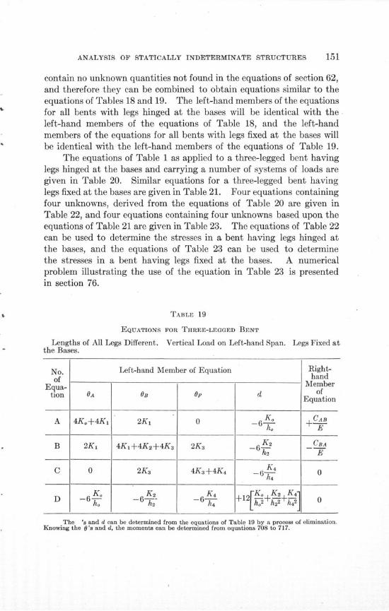
ANALYSIS OF STATICALLY INDETERMINATE STRUCTURES
contain no unknown quantities not found in the equations of section 62,and therefore they can be combined to obtain equations similar to theequations of Tables 18 and 19. The left-hand members of the equationsfor all bents with legs hinged at the bases will be identical with theleft-hand members of the equations of Table 18, and the left-handmembers of the equations for all bents with legs fixed at the bases willbe identical with the left-hand members of the equations of Table 19.
The equations of Table 1 as applied to a three-legged bent havinglegs hinged at the bases and carrying a number of systems of loads aregiven in Table 20. Similar equations for a three-legged bent havinglegs fixed at the bases are given in Table 21. Four equations containingfour unknowns, derived from the equations of Table 20 are given inTable 22, and four equations containing four unknowns based upon theequations of Table 21 are given in Table 23. The equations of Table 22can be used to determine the stresses in a bent having legs hinged atthe bases, and the equations of Table 23 can be used to determinethe stresses in a bent having legs fixed at the bases. A numericalproblem illustrating the use of the equation in Table 23 is presentedin section 76.
TABLE 19
EQUATIONS FOR THREE-LEGGED BENT
Lengths of All Legs Different. Vertical Load on Left-hand Span.the Bases.
Legs Fixed at
No. Left-hand Member of Equation Right-
of handEqua- O Member
tion OA of OF dEquation
A 4K,+4K1 2K 1 0 _--C -AB
B 2K 1 4Ki+4K2 +4K 3 2K 3 -6 K 2 CBA
h2 E
C 0 2K 3 4Ka+4K 4 -K4 0h4
D 6 Ko K 2 K4 rK L K. K 4S -6 -67- -6- +12 K+ 2] 0
The 's and d can be determined from the equations of Table 19 by a process of elimination.Knowing the 0's and d, the moments can be determined from equations 708 to 717.
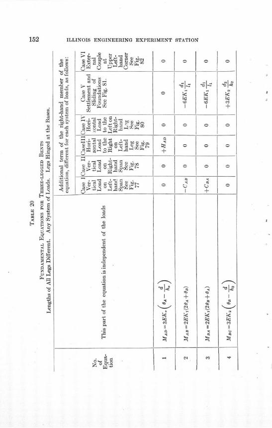
ILLINOIS ENGINEERING EXPERIMENT STATION
03 0
0** o
ID 03
C)C)
0 c
I -'0 rjt wCCr-= bl0 d90ý*lI
~0u ^ MW *
c3 0 -
0 bb
CdC
-^~b F(1)Co
'1Z
|«g. 110 b.igf (c 4
c) ce ,.ýpoo-l3 c ii PT
0
0
+
0
0
0
0
0
0
0
0
C)
bp
.0
0
E-s.
00
0 am
S
o'
. be
0 '.0
0 OC)
±
0
0
0
I
II
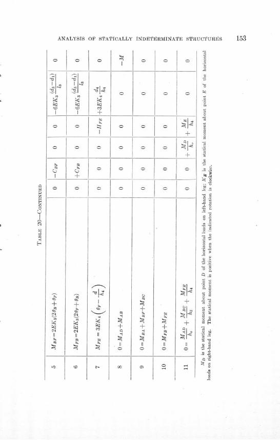
ANALYSIS OF STATICALLY INDEITRMINATE STRUCTJURES 153
0
ICC
0
0
+Cl
C<l
C).
0
0
C).
+
0
±
Cl
Cl
+
C).
-r3J.-
..~
CC
C).
+
0
+
II!
0
+
a0
m 2
o
15
o
0
a
•1-o
0
o 0
a+S
o0
3
CC___
.0 S)
- C)3C .S
§00O
S C)
.0
+ 1.0C
+°
.0.0
S'§.
bo
0 a
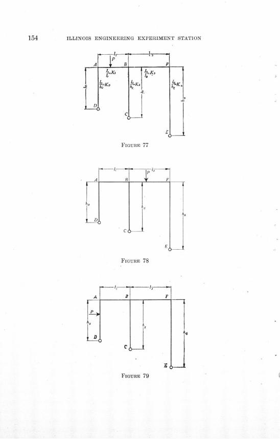
154 ILLINOIS ENGINEERING EXPERIMENT STATION
FIGURE 77
FIGURE 78
- B
_____ F
A 4
AI
FIGURE 79
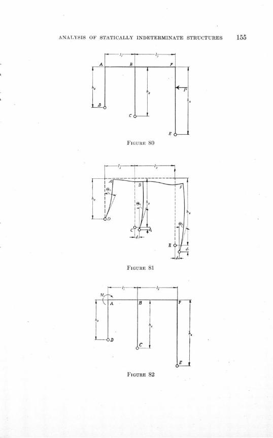
ANALYSIS OF STATICALLY INDETERMINATE STRUCTURES
FIGURE 80
FIGURE 81
17- ---MI
FIGURE 82
i \, A
I'.
U-0.
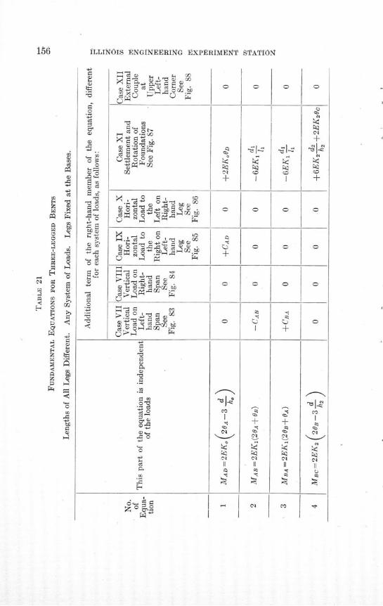
ILLINOIS ENGINoFERING tXPERIMENT STATION
u0a - S .
lia'x
Qo
02
6 a
C
,-+3o0
"0
cc
4 4 do4 ,
0 ~ C
to o oa ,.cI° .bj^^gf
•
.0 LM
O0
0i- o 4 i mo
c*• ^^ Mu
•0C
o-
Cl ^
^ I
0'I'11
<!
0
C4
0+
0
Co
C'l
H«
0
0
CC
Cl
Cl

ANALYSIS OF STrATICALLY INDETERMINATE STRUCTURES 157
0
0
0
0
±
0
T^
I0
0
+
o
a-0
+
II
¢M
'-N
CO
Cl
II
+4- A
+a-
0
0
I
II
CI
'C
GO
00
&
I
Q
+
0
0
o0
0
+4-
0
+a0-
0
0
CO
II
§¢o
±
+
+
0
0
0
Cl
0
0
0
0
0
+
0
0
o0
0
a0
0
0
+
'1
0
CO
00
0
0
0
0
0
+
0
0
+
+
0
0
+-0)
•l
u
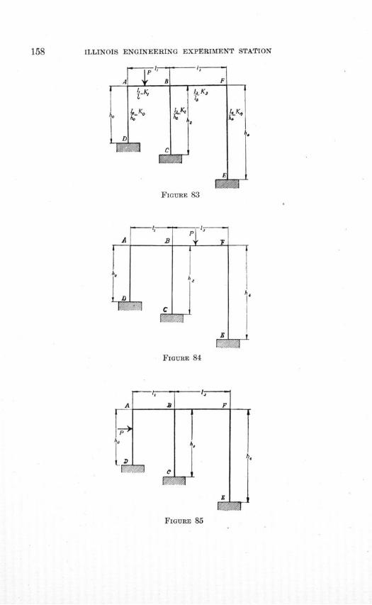
ILLINOIS ENGINEERING EXPERIMENT STATION
FIGURE 83
A B
F///
MBA
FIGURE 84
A aI
hoIPj
Ki A
F
x
FIGURE 85
-',-
aaar111=1111A
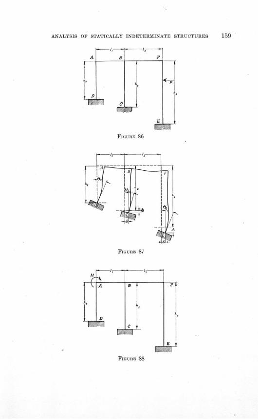
ANALYSIS OF STATICALLY INDETERMINATE STRUCTURES 159
FIGURE 86
FIGURE 87
FIGURE 88
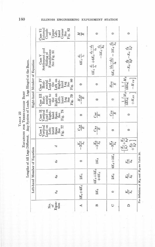
ILLINOIS ENGINEERING EXPERIMENT STATION
c~1> a) coo
c0sli:2bCU'
o a
01
A0
1 G
1 ° r. °bsa»'
1' (1: 2 ri
k ,a0- 0
0 °^
On
I03
dI
z )
0.4.;
0
o
rA
Ia
IP4CODz §
bl
1-1+
I
0
II
~0v
0
±
0
I
+
~0
CO
0
0
CO
CO+
m
0
0
+ ,4~404~
0
<w
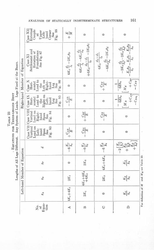
ANALYSIS OF STATICALLY INDETERMINATE STRUCTURES
C)0
C)C)0~
0
C)-oEC)
-C)C)C)-
-C)4
C)0
C)C)C)-
0
C)~0EC)
-C)C)C)
-C)
C)
* C)C)
+C^ o4
^ 4-i oCI f
0 . ' mb
co,
H0
* (
^ 0
r ý
>' + "C
tx ~ 0 C) i
,-. •- .C)
C)04C C) . C)CO
"* . C) C) C) 0
'-§^.~^
-C)a f
C)ii.
j Cj)^
C) _ rt(/
C)
Cl
0
0
±
0
Cl
+
0
+
PI
.C ,1l
ca+
I [
C)
~C) Cl
I-C)
CC) CO
+
0
0
CO
+
Cl
0
C)
-lClC)
40C)*C
XCC)
Cl ^
05
40
Q-C--43
1C°
C)
l,
-A
0 +
0
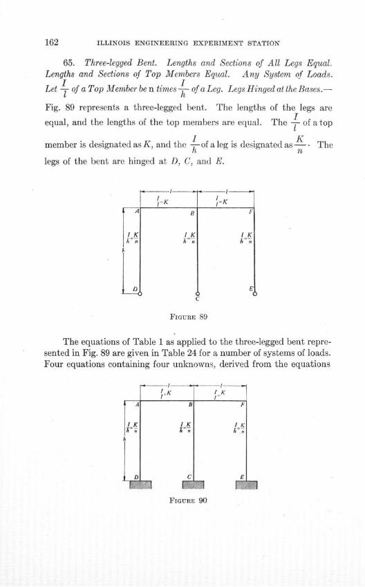
ILLINOIS ENGINEERING EXPERIMENT STATION
65. Three-legged Bent. Lengths and Sections of All Legs Equal.Lengths and Sections of Top Members Equal. Any System of Loads.
I ILet T of a Top Member be n times -C- of a Leg. Legs Hinged at the Bases.-
Fig. 89 represents a three-legged bent. The lengths of the legs areI
equal, and the lengths of the top members are equal. The - of atop
I Kmember is designated as K, and the -of a leg is designated as-. Theh nlegs of the bent are hinged at D, C, and E.
rK
-I-
'K
FIGURE 89
The equations of Table 1 as applied to the three-legged bent repre-sented in Fig. 89 are given in Table 24 for a number of systems of loads.Four equations containing four unknowns, derived from the equations
D C
IK
E
FIGURE 90
- I-l^K
VIIIIIZZIA VW111WA
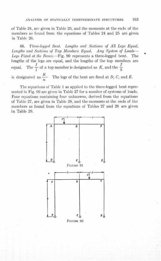
ANALYSIS OF STATICALLY INDETERMINATE STRUCTURES
of Table 24, are given in Table 25, and the moments at the ends of themembers as found from the equations of Tables 24 and 25 are givenin Table 26.
66. Three-legged Bent. Lengths and Sections of All Legs Equal.Lengths and Sections of Top Members Equal. Any System of Loads-Legs Fixed at the Bases.-Fig. 90 represents a three-legged bent. Thelengths of the legs are equal, and the lengths of the top members are
I Iequal. The - of a top member is designated as K, and the h
Kis designated as -- The legs of the bent are fixed at D, C, and E.
n
The equations of Table 1 as applied to the three-legged bent repre-sented in Fig. 90 are given in Table 27 for a number of systems of loads.Four equations containing four unknowns, derived from the equationsof Table 27, are given in Table 28, and the moments at the ends of themembers as found from the equations of Tables 27 and 28 are givenin Table 29.
B
C
FIGURE 91
a
L
F
-I--
F
HI
FIGURE 92
A
_ D
A
FIGURE 9
°I
FmURE 92I
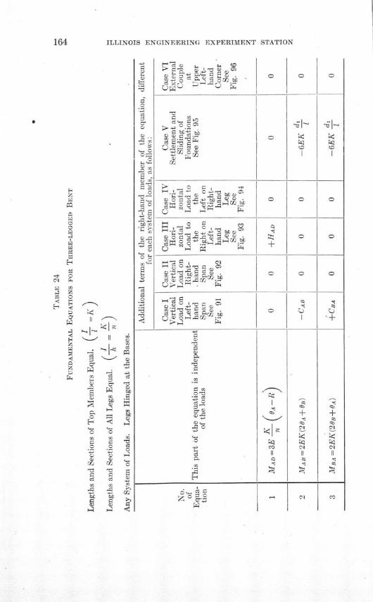
ILLINOIS ENGINEERING EXPERIMENT STATION
V
1 0 l
o 0" C)
,0 -0 <uc
1^ h12
bL 'Sl0 0 M
C)_-••C.
r4 x
Q a;Z.4
C)Cf2
0 0
i- io a ^ o -> 3ho0 w
I' -• r .d
| ] •.g
C) ig^ J )0
^^
jgg l
Q-- a c
I-. ' * 0 Cl"^ a
a,
S ^^s
0z 0
+
I
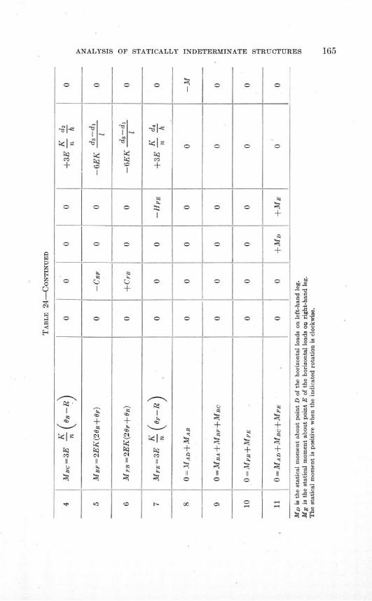
ANALYSIS OF STATICALLY INDETERMINATE STRUCTURES 165
0
+
0
0
0
0
00
0
0
4).
0
+
4).
0l
01
0
+
4).
0
0
0
+
0
00
0
0
0
0
0
0
+
+
0
0
0
0
0
0
0
+4).
0
0
0
+
+
0
0
+
+
II0
0
0
0
0
4).
0 0C3-
0
004)
0
*0 0 *|
440o 0.J. 00
. 3
*§S2
0 0.0
0 Ei
*S|4)4)4)
-- 4)
." .|
I
^
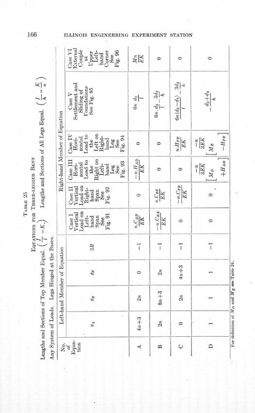
ILLINOIS ENGINEERING EXPERIMENT STATION
SI-CC'
bfl
!z o
Q >
C)
001
'4
00
C 4Io ^
0 I
o ^3
00 0
bjiC) .B~s) a
0
0
.-sJ
0 0 o .
Cd
rbb
.-•r_, o C)
02
C-) o 0fo -
C-4
_.A o o ,•0
^ ; o- s
o Co
I
CO
0
C.1
?
0
C'1-
Co
+
00.
-C)
CO
0
0
Co
+
01
-C)
C.
0
0
!V

TABLE 26
MOMENTS DUE TO VARIOUS SYSTEMS OF LOADS ON A THREE-LEGGED BENT
Lengths and Sections of Top Members Equal. = K)
Lengths and Sections of All Legs Equal. ( h )
Legs Hinged at the Bases.
Case IVertical Load on Left-hand Span
See Fig. 91
SCAB(10n+9)+CBA(4n+3)4(n+l) (4n+3)
CAB(10n+9) +CBA(4n+3)4(n+l) (4n+3)
(2n+3) [CAB( 2 n+l)+CBA(4n+3)]4(n+l) (4n+3)
CAB +CBA2(n+l)
CAB(4n ' -3)+CBA(4n+3) (2n+l)4(n+1) (4n+3)
CAB(2n+3)-CBA(4n+3)4(n+1) (4n+3)
CAB(2 n+ 3
) -CBA(4n+3)4(n+l) (4n+3)
Case IIVertical Load on Right-hand Span
See Fig. 92
CBF(4n+3) -CFB(2n +3)4(n+1) (4n+3)
CBF(4n+3)-CFB(2n+3)4(n+l) (4n+3)
CBF(4n+3) (2n+1)+CFB(4n 2 -3)4(n+1) (4n+3)
CBF •±CFB2(n+l)
(2n+3) [CBF(4n+3)+CFB(2n+l)]4(n+1) (4n+3)
CBF(4n+3)+CfB(10n+9)+ 4(n+1) (4n+3)
CBF(4n+ 3 ) +C1FB(IOn+9)4(n+l) (4n+3)
Case IIIHorizontal Load to the Right on
Left-hand LegSee Fig. 93
2nHAD(16n+15) -MD(4n+3) 2
12(n+1) (4n+3)
2nHAD(16n+15) -MD(4n+3) 2
12(n+l) (4n+3)
(2n+3) [2nHAD-MD(4 n+ 3 )]12(n+l) (4n+3)
2nHAD+MD(2n+3)6(n+1)
2nHAD(10n+9)+MD(4n+3) (2n+3)+ 12(n+1) (4n+3)
2nHAD(8n+9) +MD(4n+3)2
+ 12(n+l) (4n+3)
2nHAD(Sn+9) +MD(4n+3)'12(n+l) (4n+3)
Case IVHorizontal Load to the Left on
Right-hand LegSee Fig. 94
2nHFE(8n+9) - ME(4n+3) 2
12(n+1l) (4n+3)
2nHFE(8n+9) -ME(4n+3) 2
12(n+1) (4n+3)
2nHFE(0ln+9)-ME(4n+3) (2n+3)12(n+1) (4n+3)
2nHFE-ME(2n+3)6(n+1)
(2n+3) [2nHFE+ME(4n+3)]12(n+l) (4n+3)
2nHFE(16n+15)+ME(4n+3)2
-1 12(n+1) (4n+3)
2nHFE(1 6n+15) +ME(4n+3) 2
12(n+1l) (4n+3)
Case VSettlement and Sliding
of FoundationSee Fig. 95
EK 18h(n+1l) (2di-d 3)-1 [d2(8n+6) +d 4(8n+9)]-2hl (n+l) (4n+3)
EK . 18h(n+1) (2di-d 3 )-l [d2 (8n+6)+d4(8n+9)]2hl (n+1) (4n+3)
EK . 6h(n+1) (2n+3) (2di-d 3)+l [d2(8n+6) -d 4 (10n+9)]2hl (n+1) (4n+3)
EK . 2d 2 -d 4h n+1
EK . 6h(n+1) (2n+3) (2di-d 3)-l [d2 (8n+6)+d4(2n+3)]"2hl (n+1) (4n+3)
EK . 18h(n+l) (2di-da)+l[d2(Sn+6)-d 4 (16n+15)]2hl (n+1) (4n+3)
EK . 18h(n+l1) (2di-d3)+l [d2(8n+6) -d 4 (16n+15)]2hl (n+l) (4n+3)
Case VIExternal Couple at
Upper Left-handCorner
See Fig. 96
+ M(10n+9)'4(n+l) (4n+3)
M(16n±+18n+3)- 4(n+l) (4n+3)
M(2n+l) (2n+3)S4(n+l) (4n+3)
M2(n+l)
M(4n2 -3)4(n+1) (4n+3)
M(2n +3)+4(n+1l) (4n+3)
M(2n+3)4(n+l) (4n+3)
For definition of MD and ME see Table 24.
No.of
Equa-tion
3
4
5
6
7
Mo-ment
MAD
MAB=
MBA
MBc=
MBF =
MFB=
MpE
ýl I--1 1 -1
-1 1 1
i I II II

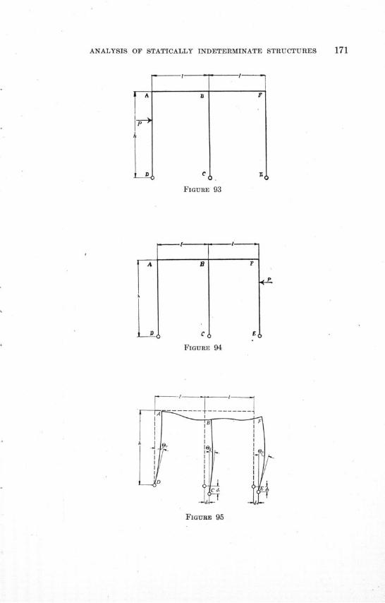
ANALYSIS OF STATICALLY INDETERMINATE STRUCTURES
FIGURE 93
C
FIGURE 94
FIGURE 95
-I---
I
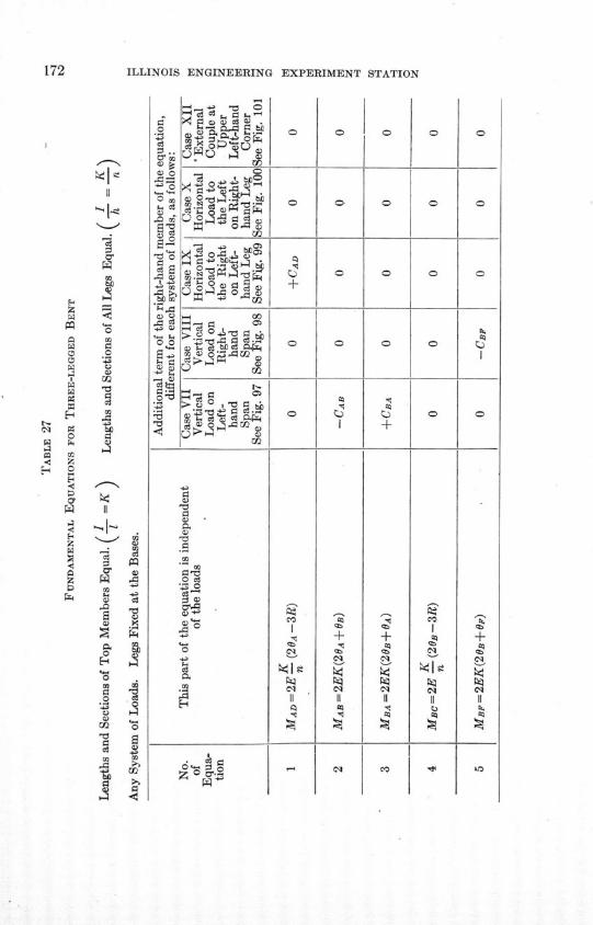
ILLINOIS ENGINEERING EXPERIMENT STATION
a 0g
C m
z z
E2
2
m< E
S ri .-
0
&
I
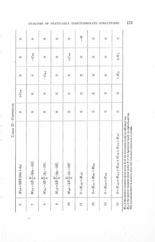
ANALYSIS OF STATICALLY INDETERMINATE STRUCTURES 173
0
CO
C"
C"
0
CO
C"
I<
<&
0
CO
Cl
0
CeI
21
Cl
0
0
+
0
0
+
+
0
010
0
0
+
0
0
0
+
+
+
+
+q
0
§0.0
.0.
^ .j0 0 *3°00,0
0-* "
-0,
do,.,00,S0
0.00I
.1
0^
0 0l
||0 §~ .
j00,'^ 3
o o o*i000S S-a a *0,S
*s .a05 0.S
0,0,
0
+
C"
Cl
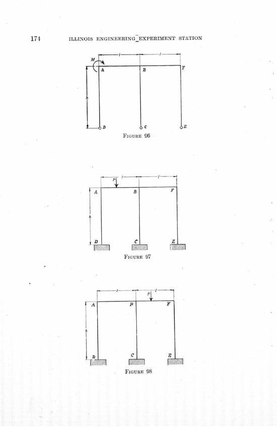
174 ILLINOIS ENGINEERING EXPERIMENT STATION
M A*------
B
iC
FIGURE 96
FIGURE 97
FIGURE 98
F
FIGURE 96

ANALYSIS OF STATICALLY INDETERMINATE STRUCTURES
scaS00
H00H
o I
^ ^0
02 g4- 0--\
o 0^
4.. .
0 0
00
.4. -4. 0172bf t fl
0
4-§
*.0
^00u
4-0
g0
0
4-
S
.0
•2 0 . !-
0°0 0
¢o
S^^
4-40
42 cý 0 0 f>! f cl 0
.5 0 .cIs
Co
oI 540
+
0
+
0
.) P4
+
0
0
0
+0 K
sS
+
0
70
^S
0 &
<S
S
S
±S
S
0
0
-4
-4
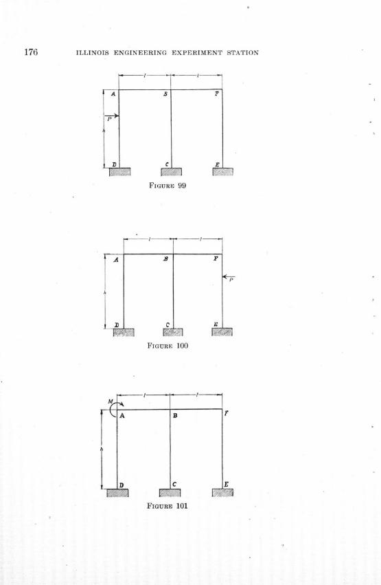
ILLINOIS ENGINEERING EXPERIMENT STATION
S
C
P
£
FIGURE IFIGURE 99
FIGURE 100
FIGURE 101
A
""I
FIGURE 99
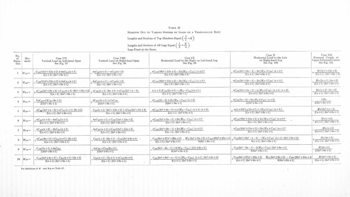
TABLE 29
NIOMENTS DUE TO VARIOUS SYSTEMS OF LOADS ON A THREE-LEGGED BENT
Lengths and Sections of Top Members Equal.( ' =K)
Lengths and Sections of All Legs Equal. (T..= •)-
Legs Fixed at the Bases.
Case VIIVertical Load on Left-hand Span
See Fig. 97
CAB(11n2
±+15n + 2 ) +4nCBA(nB+l)2(n+l) (6n 2+9n+l)
CAB(lln'+1
5n+2
)"+4nCBA(n+1)
2(nf l) (On +9n+1)
nCAB( 3 n'+ 8n+4)+CBA(n+1) (6nf2+13n+2)
7nCAB+2CBA(4n+1)
2(6n2+9n+l)
nCAp(3n2+n-3)+nCBA(n+l) (6n+5)2(n+l) (6n 2+9n+l)
+ nCAB(n+ 3 ) -4nCBA(n+l)2(n+1) (6n 2+9n+1)
nCAB(n+3) -4nCBA(n+1)2(n+l) (6n 2+9n+l)
nCAB(4n+5)+CBA(n+l) (2n+l)2(n+l) (6n 2+9n+1)
CAB(5n+l)+4nCBA2(6n 2+9n+l1)
CAB(2nl2+4n+l)-CBA(n+l) (2n+l)
Case VIIIVertical Load on Right-hand Span
See Fig. 98
4nCBF(n+1) -nCFB(n+3)2(n+1) (6n 2 +9n+1)
4nCBF(n+l) -nCFB(n+3)2(n+1) (6n 2+9n+l)
nCBF(n+l) (6n+5)+nCFB(3n+n-3)I ~ ~ ~~ 6/. 2 9i\/>.* l^
2CBF(4n+l) +7nCFB2(6n2 +9n+1)
CBF(n+1) (6n 2+13n+2) +nCFB(3n2+8n+4 )2(n+l1) (6n 2+9n+1)
4nCBF(n+l) +CFB(lln 2 +15n+2)2(n+l) (6n 2+9n+l)
4nCBF(n+l) +CFB(lln2+15n+2
)
2(n+1) (6n?+9n+1)
CBF(n+1) (2n+1)-CFB( 2 n 2+ 4 n+l)2(n+1) (6n2+9n+1)
4nCBF+CFB(5n+l)
- 2(6O2 +9n+1)
Case IXHorizontal Load to the Right on Left-hand Leg
See Fig. 99
, nCAD(1Onr+15n+3)-2n(MD-CDA) (n+1) 2
2(n+l) (6n2+9n+1)
nCAD(10n2+15n+3 )-2n(MD-CDA) (n+1) 2
2(n+1) (6n2 +9n+ 1)
n(n+2) [CAD(2n+l) - (MD-CDA)(n+l)]
2(n+1) (6n 2+9n+l)
nCAD(2n-3)+2n(MD-CDA) (n+2)
2(6n2+9n+1)
nCAD(4n2+4n-1)+n(MD-CDA) (n+1) (n+2)
2(n+1) (6n 2+9n+l)
nCAD(2n2+3n-1)+2n(MD-CDA) (n+1)2
+ 2(n+1) (6n 2+9n+l)
nCAD(2
n2+3n-1)+2n(MD-CDA) (n+1)2
2(n+l) (6n2+9n +1)
CAD(6n3 + 2 7
n2
+2 6
n+2) MD (6n2 + 9n+2) +CDA(30n 2+45n+4)
6(n+l) (6n 2+9n+l) 6(6n2 +9n+1)
CAD(6n2-3n-l)+2 (MD-CDA) (3n'+6n+l)
6(6n 2+9n+l)
CAD(6n9n2--n-l1)+(MD-CDA) (n+l) (6n2+9n+2)
6(n+l) (6n2+9n-+1)
Case XHorizontal Load to the Left
on Right-hand LegSee Fig. 100
+nCFE(2n2+3n-1)-2n(ME+CEF) (n+1)2
2(n+l) (6n 2+9n+1)
nCPE(2n+3n-1) -2n(ME+CEF) (n+1)2
2(n+1) (6n2+9n+1)
nCFE(4n2+4n-1)-n(ME+CEF) (n+1) (n+2)
2(n+l) (6n2+9n+1)
, nCFE(2n-3)-2n(ME+CEF) (n+2)2(6n2+9n+l)
n(n+2)[CFE(2n+l)+(ME+C EF) (n+l)]2(n+l) (6n2+9n+1)
nCFE(10n+-15n+3)-2n(ME+CEF) (n+1)2+ 2(n+l) (6n 2+9n+l1)
nCFE(10n2+15n+3)+2n(ME+CEF) (n+l)2
2(n+l1) (6n 2+9n+l)
, CFE(6n3
+9n2 -
n -l)-(ME+CEF) (n+1) (6n2+9n+2)
6(n+l) (6n2+9n+l)
, CFE(6n 2 -3n-1)-2(ME+CEF) (3n 2+6n+1)6(6n2+9n+l)
CFE(6n3 +27n 2+26n+2) ME (6n+9n+2) - CEP (30n'+45n+4+ 6(n+l) (6n 2+9n+l) 6(6n2+9n+l)
Case XIIExternal Couple at
Upper Left-hand CornerSee Fig. 101
M(lln2+15n+2)2(n+1) (6nI+9n+1)
Mn(3n+1) (4n+5)2(n+1) (6n'+9n+l)
Mn(n+2) (3n+2)2(n+1l) (6n2+9n+1)
7Mn2(6n2 ÷g+9n+1)
Mn(3nS+n-3)
2(n+l) (6n2+9n+1)
Mn(n+3)+2(n+l) (6n2+9n+1)
Mn(n+3)2(n+l) (6n2+9n+l)
Mn(4n+5)2(n+1) (6nk+9n+l)
M(5n+l)2(6n2+9n+l)
M(2n2+4n+l)2(n+l) (6nf+9n+1)
For definitions of M and ME see Table 27.
INO.of
Equa-tion
6
7
Mo-ment
MAD
M AB=
MBA=
Mic =
MBF=
MFB =
MDA
MCB
MEFP=2(n+1) (6n 2+9n+1)
CBF(n+l) (2n+l)+nCFB(4n+5)2(n+l) (6n 2+9n+1)
1--k i -I- I- I-I -I-
i I-I- - I-I I-
--II I-
-I- I I I - I-
-- I- .1 1-.1 1I-
-1
-1 -1
I-1 1
-1 -1 1 ---------------------------- -I-
ýl - - - 1; -, -, - . 7 -'.. I.I-
n(2 +1) (6n +9n+ )
n(2 + ) ( n + nf )

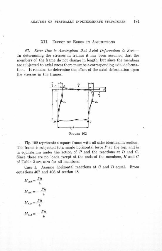
ANALYSIS OF STATICALLY INDETERMINATE STRUCTURES
XII. EFFECT OF ERROR IN ASSUMPTIONS
67. Error Due to Assumption that Axial Deformation is Zero.-In determining the stresses in frames it has been assumed that -themembers of the frame do not change in length, but since the membersare subjected to axial stress there must be a corresponding axial deforma-tion. It remains to determine the effect of the axial deformation uponthe stresses in the frames.
FIGURE 102
Fig. 102 represents a square frame with all sides identical in section.The frame is subjected to a single horizontal force P at the top, and isin equilibrium under the action of P and the reactions at D and C.Since there are no loads except at the ends of the members, H and Cof Table 2 are zero for all members.
Case 1. Assume horizontal reactions at C and D equal. Fromequations 407 and 408 of section 48
PhMAB=-J-4
MBC Ph
M C Ph4
MDA =- Ph4
ILLINOIS ENGINEERING EXPERIMENT STATION
AD= MAD ±MI)A 1 pShear in AD= MAD .-
h 2Likewise
Shear in BC= 1 P21
Shear in AB=- P2
Shear in DC = - P
-Stress in AB= P compression
Stress in CD = 0
Stress in AD = -P tension2
Stress in BC = .- P compression2
Since AB, AD, and BC have the same sections, the same lengths,and are subjected to axial stresses of the same magnitudes, A h, repre-senting the change in length due to axial stress, is the same for allmembers.
Referring to Fig. 102
Ah Ph 2AE
2Ah _ P
I AE
Applying the equations of Table 1 gives
MAB=2EK(20A+ O-3R3) . . . . . . . .. . (719)
MA,= -2EK(20A+OD- 3R 1) ......... (720)
MBc=2EK(20B+Oc- 3R 2) (721)
ANALYSIS OF STATICALLY INDETERMINATE STRUCTURES 183
MBc= -2EK(2 Bs+ A-3Ra) . . . . . .... . (722)
MCD=2EK(2ec+9D) . . . . .. . . . . . (723)
McD=-2EK(20c+ 06-3R2 ) . .. . . . .. (724)
MDA = 2EK(2 0D + OA- 3RI) . . .. . . . . . (725)
MDA= -2EK(20D+0c) . . . . ... . . . (726)
For AD and BC to be in equilibrium
-MAB+MBc-McD+MDA+Pl=O . . . . .... . (727)
Combining equations 719 to 727, substituting values for R1, R2,and Ra, and solving for the moments gives
MAR= 1 . ..... .......... (728)
4 2Ah..........
M CD = P + 3K . . . . . . . . . . . (730)
Ph K....... (731)MA=-4[ + . . . . . . . . . .(730)
9KIn these equations 2-- represents the largest error due to neg-
9Klecting the axial deformation in the members, and the ratio of 9K to 1
2Ahrepresents the relative error.
Case 2. Assume horizontal reaction at C only. If the horizontalreaction is all taken at C
1Stress in AB = - P compression
1Stress in CD = -P compression
2
ILLINOIS ENGINEERING EXPERIMENT STATION
1Stress in AD =-P tension
2
Stress in BC =--P compression
Since AB, CD, AD, and BC have the same sections, the samelengths, and are subjected to axial stresses of the same magnitude,Ah, representing the change in length due to axial stress, is the same forall members. The magnitude of Ah is given by the expression
PhAh= P
2AE
As Ah for AB equals Ah for DC, Ri= Rs
Since AD is in tension and BC in compression
R 2Ah P" 1 A-E
Equations 719 to 727 are applicable. Combining the equations,substituting the values of the R's and solving for the moments gives
MBC Ph 1 6KM =-- (1--II..) . .......... (733)
MCD= Ph .(1 + K) ............. (734)
MDA =-- P(1+ 6K)(735)
P 6K
In these equations - represents the error due to neglecting the6K
axial deformation in the members, and the ratio of 6- to 1 representsthe relative error.
the relative error.
ANALYSIS OF STATICALLY INDETERMINATE STRUCTURES
Comparing Case 1 with Case 2, it is apparent that the error dueto neglecting the axial deformations is smaller if the horizontal reactionis all at one corner than if half of it comes at each of the lower corners.
9KThe maximum relative error, for Case 1, is -- " Substituting for K
2Ah 9K 9
its value -T- the expression - becomes . That is, the error dueT 2Ah 2Ah 2
to neglecting the axial deformation in a square frame with all sidesidentical, subjected to a single horizontal force at the top, varies directlywith the moments of inertia of the section of the members, inverselywith the area of the members, and inversely with the square of thelength.
If for Case 1 the frame, instead of being square as shown in Fig. 102,is a rectangle twice as wide as it is high, and if the sections of all membersare identical, the moments in the frame due to a single horizontal forceP at the top are
MA= ( T ) . . . . . . . . . . (736)
Ph 9 K \ 7
MCD= 4 --(1) . . . . . . . . . . (738)
15 15 K
The maximum relative error in this case is - -r divided by 1.
9 Kless than - , the coefficient of J--, in equation 731. Hence for two
frames, one a rectangle twice as wide as it is high with sections of allmembers identical, and the other a square having all sides identicalwith the vertical sides of the rectangle, and both frames having a
ILLINOIS ENGINEERING EXPERIMENT STATION
single horizontal force applied at the top, the error due to axial deforma-tion is less for the rectangular frame than it is for the square frame.
If for Case 1 the frame, instead of being square as shown in Fig. 102,is a rectangle twice as high as it is wide, and if the sections of all membersare identical, the moments in the frame due to a single horizontalforce P at the top are
Ph, (1 51 K (740)MAB =-~ -4 8Th-) .... . ............
MC= - 1- . . .. . . . . . . (741)
M 1 . . . . . . . . (742)
M = - . . .. . . . . . . . (743)
in which h and K are for the vertical members.
51 KThe maximum relative error in this case is - -j divided by 1.
It is to be noted that - , the coefficient of - in equation 743, is8 Ah
9 Kmore than --- , the coefficient of - in equation 731. Hence for two
frames, one a rectangle twice as high as it is wide with sections of allmembers identical, and the other a square having all sides identicalwith the vertical sides of the rectangle, and both frames having a singlehorizontal force at the top, the error due to axial deformation is greaterfor the rectangular frame than it is for the square frame.
Table 30 gives the errors due to axial deformations in a number ofrectangular frames. The largest error in the table is 3.70 per centfor a frame 10 feet square composed of 27 in.-83 lb.-I-beams. Althoughthis frame is composed of members having sectional areas so large com-pared with their length that it would be impracticable to provide con-nections strong enough to develop the strength of the members, yetthe error, 3.7 per cent, is well within the range of permissible error.For steel frames of the proportions common in engineering structures
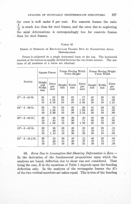
ANALYSIS OF STATICALLY INDETERMINATE STRUCTURES
the error is well under 2 per cent. For concrete frames the ratioI.A is much less than for steel frames, and the error due to neglecting
the axial deformations is correspondingly less for concrete framesthan for steel frames.
TABLE 30
ERROR IN STRESSES IN RECTANGULAR FRAMES DUE TO NEGLECTING AXIAL
DEFORMATION
Frame is subjected to a single horizontal force at the top. The horizontalreaction at the bottom is equally divided between the two lower corners. The sec-tions of all members of a frame are identical.
Frame Having Width Frame Having Heightquare Frame Twice Height Twice Width
Section Height Errorand Height Width Error Height Width Error
Width per feet feet per feet feet perfeet cent cent cent
27"-I-83 lb. 20 .92 20 40 .77 40 20 .3315 1.64 15 30 1.37 30 15 .5810 3.70 10 20 3.08 20 10 1.31
24"-I-80 lb. 20 .70 20 40 .58 40 20 .2515 1.24 15 30 1.03 30 15 .4310 2.80 10 20 2.33 20 10 .99
20"-I-65 lb.: 20 .48 20 40 .40 40 20 .1715 .85 15 30 .71 30 15 .3010 1.92 10 20 1.60 20 10 .68
15"-I--42 lb. 20 .28 20 40 .23 40 20 .1015 .49 15 30 .41 30 15 .1710 1.10 10 20 .92 20 10 -.39
12"-I-31.5 lb. 20 .18 20 40 .15 40 20 .0615 .32 15 30 .27 30 15 .1110 .73 10 20 .61 20 10 .26
68. Error Due to Assumption that Shearing Deformation is Zero.-
In the derivation of the fundamental propositions upon which the
analyses are based, deflection due to shear was not considered. That
being the case, R in the equations of Table 1 depends upon the bending
deflection only. In the analyses of the rectangular frames the R's
of the two vertical members are taken equal. This is true of the bending
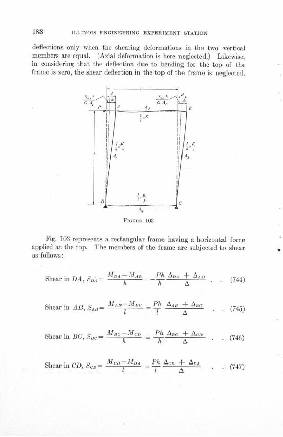
ILLINOIS ENGINEERING EXPERIMENT STATION
deflections only when the shearing deformations in the two verticalmembers are equal. (Axial deformation is here neglected.) Likewise,in considering that the deflection due to bending for the top of theframe is zero, the shear deflection in the top of the frame is neglected.
FIGURE 103
Fig. 103 represents a rectangular frame having a horizontal forceapplied at the top. The members of the frame are subjected to shearas follows:
MDa--MAn Ph ADA + &ABShear in DA, SDA - M MAB Ph ADA + AAh h A
Shear in AB, SaD= MAB-Mic Ph AAB + A.c1 T A
Shear in BC, SBc= MB-MCD Ph ABc + Aco
Shearh h A
Shear in CD, ScD = MCD-MDA = Ph AcD + ADA
(744)
. . (745)
(746)
. (747)
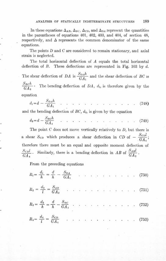
ANALYSIS OF STATICALLY INDETERMINATE STRUCTURES 189
In these equations AAB, ABC, ACD, and ADA represent the quantitiesin the parentheses of equations 401, 402, 403, and 404, of section 48,respectively, and A represents the common denominator of the sameequations.
The points D and C are considered to remain stationary, and axialstrain is neglected.
The total horizontal deflection of A equals the total horizontaldeflection of B. These deflections are represented in Fig. 103 by d.
SDAhThe shear deflection of DA is - and the shear deflection of BC isGA,SBchS-- . The bending deflection of DA, di, is therefore given by theGA3
equation
SDA7dl=d - A. (748)-- GA . . . . . . . . . . .. . . . . . (748)
and the bending deflection of BC, d3, is given by the equation
d =d- . . . . . . . . . . .. . (749)
The point C does not move vertically relatively to D, but there is
a shear SCD which produces a shear deflection in CD of - CD1.GA4
therefore there must be an equal and opposite moment deflection of
ScD1l Similarly, there is a bending deflection in AB of SaB'GA 4 GA,2
From the preceding equations
d= d SIaR h GA - 1 . . . . . . . . . . (750)
d Sa . . . . . . . . . . . . (751)2 -1 GA 2 .. . . . . . . . . . (751)
R3 ds d Sach - h -GA, . . . . .. . . . . (752)
d 4 SCDR4= T 1 GA, . . . . . . . . . . . . (753)
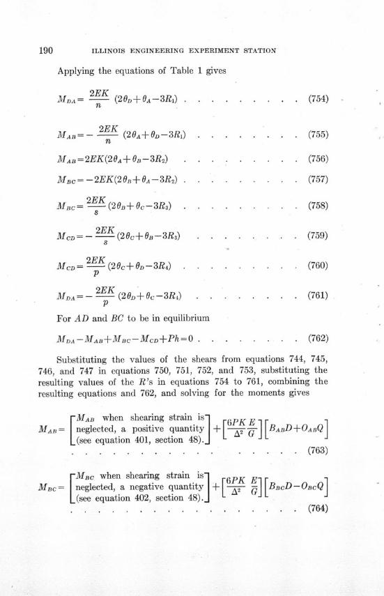
ILLINOIS ENGINEERING EXPERIMENT STATION
Applying the equations of Table 1 gives
2EKMDA= -- (20D+0A--3R 1) . . . . . . . . . (754)
n
2EKMAB=- K (20A+OD-3R 1) . . . . . . . . (755)
n
MAB=2EK(20A+OB-3R2) . . . . . . . . . (756)
MBc= -2EK(20B 0A-3R 2) . . . . . . . (757)
MBc= 2 (20B+ 0c-3R3) . . . . . . . . . (758)8
2EKMcD= -- (2c+ 0B-3R3) . . .. . . . . (759)
Mc= 2 (20c+ -3R 4) . . . . . . . . . (760)
2EKMDA= -- (2O 0+c-3R4) . . . . . . . . (761)
For AD and BC to be in equilibrium
MDA-MAB+MBC-MCD+Ph=O . . . . . . . . (762)
Substituting the values of the shears from equations 744, 745,746, and 747 in equations 750, 751, 752, and 753, substituting theresulting values of the R's in equations 754 to 761, combining theresulting equations and 762, and solving for the moments gives
[ MAB when shearing strain is + [6PK
MAB = neglected, a positive quantity + G BABDD+OABQ(see equation 401, section 48). J L J. . . . . . . . . . . . . . . . (763)
[Mac when shearing strain is 6PK EMBC= neglected, a negative quantity + 2-•- BBcD-OBCQ
(see equation 402, section 48). L. . .. . . . . . . (764)
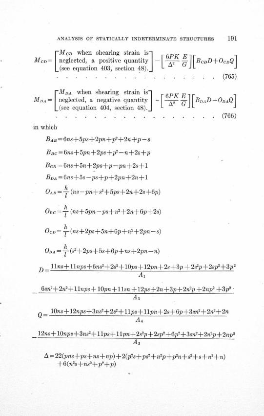
ANALYSIS OF STATICALLY INDETERMINATE STRUCTURES 191
[MCD when shearing strain is 6PK EMCD = neglected, a positive quantity - E E BcDD+OcDQ
[(see equation 403, section 48).J JL
. .. . . . . . . . . . . . . . . (765)
rMDA when shearing strain is]- E]
MDA = [neglected, a negative quantity - [ 6PK [BDAD - ODAQ
[(see equation 404, section 48).J L -
. . . . . . . . . . . . . . . . . (766)
in which
BAB =6ns+5ps+2pn+p2+2n+p--s
BBc = 6ns+5pn+2ps+p2-n+2s+p
BCD =6ns+5n+2ps+p-pn+2s+1
BDA =6ns+5s-ps+p+2pn+2n+l
hOAR = T (ns-pn+s2 +5ps+2n+2s+6p)
OBC=-f- (ns+5pn-ps+n2+2n+6p+2s)
OCD= - (ns+ 2 ps+5n+6p+n2+2pn-s)
ODA = - (s2 -+2 ps+5s+6p+ns+2pn-n)
D = llns+llnps+6ns2+2s 2+0lps+12pn+2s3p +2s 2p+2sp2+3p 2
Ai
6sn 2+2n 2+llnps+ 10pn+1lsn +12ps+2n+3p+2n'p +2np 2 + 3 p2
As
S10lOns+12nps+3ns 2+2s 2+llps+llpn+2s+6p+3snl+2n 2+2n
A 4
12ns+10nps+3ns 2+llps+llpn+2s 2p+2sp2 -6p 2+3sn 2+2n'p+2np2
A 2
A = 22(pns+ps+ns+np) +2(p 2s+ps2 +n 2p+p 2n+se+s+n2 +n)+6(n 2s+ns2±p2+p)
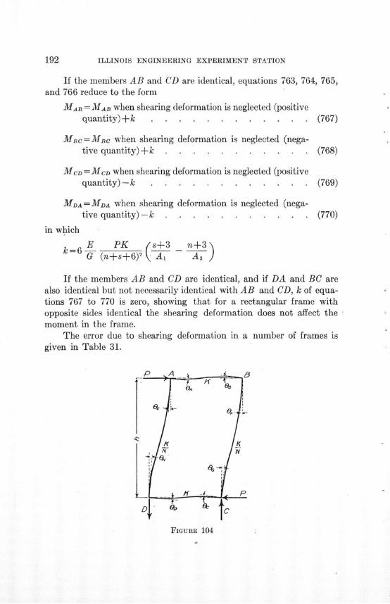
ILLINOIS ENGINEERING EXPERIMENT STATION
If the members AB and CD are identical, equations 763, 764, 765,and 766 reduce to the form
MAB = MAB when shearing deformation is neglected (positivequantity)+ k . . . .. . . . . . . (767)
MBc=MBC when shearing deformation is neglected (nega-tive quantity)+ k . . .. . . . . . . (768)
MCD =MCD when shearing deformation is neglected (positivequantity) - k . . .. . . . . . . . (769)
MDA = MDA when shearing deformation is neglected (nega-tive quantity) - k . .. . . . . . . . (770)
in which
E PK (s+3 n+3G (n+s+6)2 A1 As
If the members AB and CD are identical, and if DA and BC arealso identical but not necessarily identical with AB and CD, k of equa-tions 767 to 770 is zero, showing that for a rectangular frame withopposite sides identical the shearing deformation does not affect themoment in the frame.
The error due to shearing deformation in a number of frames isgiven in Table 31.
FIGURE 104
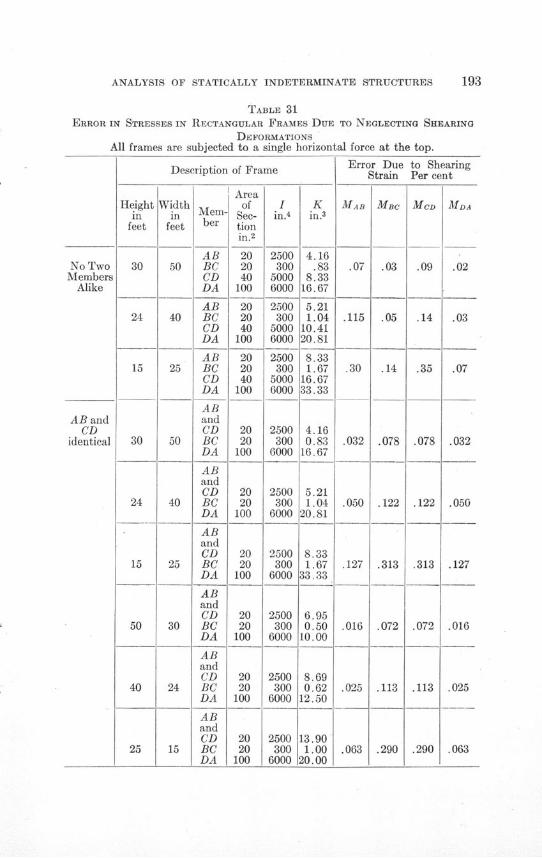
ANALYSIS OF STATICALLY INDETERMINATE STRUCTURES
TABLE 31ERROR IN STRESSES IN RECTANGULAR FRAMES DUE TO NEGLECTING SHEARING
DEFORMATIONSAll frames are subjected to a single horizontal force at the top.
Description of Frame
Widthin
feet
50
25
30
24
Heightin
feetMem-ber
ABBCCDDA
ABBCCDDA
ABBCCDDA
ABandCDBCDA
ABandCDBCDA
ABandCDBCDA
ABandCDBCDA
ABandCDBCDA
ABandCDBCDA
ofSec-tionin.2
202040
100
202040
100
202040
100
2020
100
2020
100
2020
100
2020
100
2020
100
2020
100
Description of Frame
Error Due to ShearingStrain Per cent
MAB
.07
.115
.30
A A
MBc
.03
.05
.14
No TwoMembers
Alike
AB andCD
identical
MCD
.09
.14
.35
Iin.
4
2500300
50006000
2500300
50006000
2500300
50006000
2500300
6000
2500300
6000
2500300
6000
2500300
6000
2500300
6000
2500300
6000
Kin.
3
4.16.83
8.3316.67
5.211.04
10.4120.81
8.331.67
16.6733.33
4.160.83
16.67
5.211.04
20.81
8.331.67
33.33
6.950.5010.00
8.690.62
12.50
13.901.0020.00
MDA
.02
.03
.07
.032
.050
.127
.016
.025
.063
.078
.122
.313
.072
.113
.290
.050
.127
30
15
50
40
.016
.025
.063
.078
.122
.313
.072
.113
.290
ILLINOIS ENGINEERING EXPERIMENT STATION
69. Effect of Slip in the Connections upon the Moments in a Rec-tangular Frame Having a Single Horizontal Force at the Top.-Fig. 104represents a rectangular frame having a single horizontal force appliedat the top. The sections of opposite sides of the frame are identical.The connections at the corners of the frame slip.
The changes in the slopes at the ends of the member AB are repre-sented by OA at A and OB at B; likewise for the member CD the changein slope at C is represented by Oc and at D by OD; for the member ADthe change in slope at A is represented by O0 and at D by O,; and forthe member BC the change in slope at B is represented by 0, and at Cby 0
G. That is: slip at A equals OE-OA; slip at B equals O-OBs; slipat C equals OG-Oc; and slip at D equals OH-OD.
I I KRepresent I for AB and CD by K, and - for AD and BC by -K
Applying equation A, Table 1, and equating the sum of the momentsat each of the points A, B, C, and D to zero and also equating the sumsof the moments at the ends of the two members AD and BC to -Phgives
2EK(20A +B)+ 2 E (20E+ H-3R)=0 . . . . . . (771)n
2EK2EK(20B+OA)+ (20+0G-3R)=0 . . . . . . (772)
2EK(20c+0D)+ 2EK(20G+ 0F-3R) =0 . . . . . (773)
2EK -2EK(20D+Oc)+ -• (20+ OE-3R)=0 . . . ... . (774)
2EK (20E+ OH-3R+20H+ O-3R+20F +0o-3R+200 +OFn
-3R)+Ph=0 ........... . (775)
Letting A represent the quantity, slip at A divided by R, likewiseletting B, C, and D represent the corresponding quantities at the pointsB, C, and D, respectively, gives
A OE OAR R
ANALYSIS OF STATICALLY INDETERMINATE STRUCTURES
B OF 0•R R?
C= 0CB R R
D= OH 01R R
Substituting the values of 0E, Or, O0, and OH from these equationsin the preceding equations gives
20Al _ OB OD 1 /1 +n) + + =- 3-2A-D . . . . . (776)
2OB/ \ OA A c i B cnR )+f R n 3-2.B-C. . . . . . (777)
20c/ \ + OBD () = 1(7nR 1 +n)+-+nR-= (3-2C-B) . . . . . (778)
20D \ 0C OA 1/2n Ol+n)
+- L'+ nR=n 1(3-2D-A) . . . . . . (779)
- Phn2EKR =
- [+I+-- +- - +4- (A+B+C +D). . (780)
These five equations contain four unknown angles and one unknowndeflection. Solving these equations and substituting the values forthe O's and R in the expressions for the moments gives
1 Ph3 4-(A+B+C+D)
[(6A+3B-9)+n(16A+5B+4C+5D -30)+n 2(6A+3D-9)(n+3) (3n+1) I
. . . . . . . . .. . . . . . . (781)
ILLINOIS ENGINEERING EXPERIMENT STATION
1 PhM 3 4-(A+B+C+D)
[(6D+3C-9)+n (16D+5C+4B+5A -30)+n 2(6D+3A -9)]
[ (n+3) (3n+1) J. . . . . . . . . . . . . . . . . (782)
1 PhB 3 4-(A+B+C+D)
[(6B+3A-9)+n(16B+5A+4D+5C-30)+n (6B+3C-9)
[I (n+3) (3n+1) ]. . . . . . . . . . . . . .... . (783)
1 Phc n 3 4-(A+B+C+D)
(6C+3D-9)+n(16C+5D+4A+5B-30) +n2(6C+3B-9)
I (n+3) (3n+1) ]. . . . . . . . . . . . . . . . (784)
The values of LA -, 1-, and -D determined from equations 776
to 779 substituted in equation 780 gives
R= &[(RA+RB+RC+RD)+- Phj . (785)
in which RA, RB, RC, and RD represent the slips in the connectionsat A, B, C, and D respectively. If the slips are measured, R may becomputed from equation 786. Knowing R and the slips, the values ofA, B, C, and D may be computed. Substituting the values of A, B, C,
and D in equations 781 to 784, the moments in a frame having connec-
tions which are not rigid may be determined.If there is no slip in the connections the moment at each corner
of the frame of Fig. 104 is - '4Ph. The differences between -14 Ph
and the moments given by equations 781, 782, 783, and 784 representthe effect of the slip in the connections.
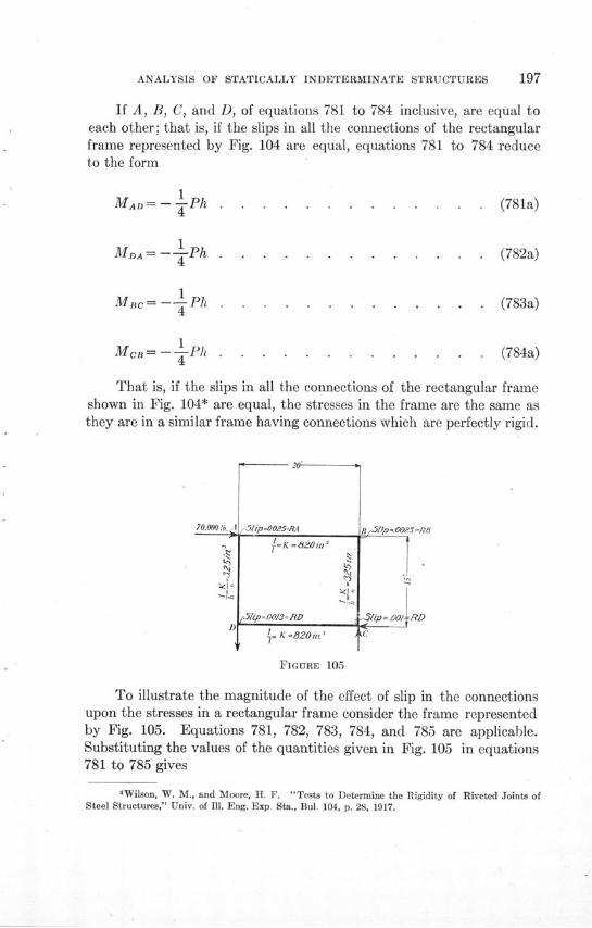
ANALYSIS OF STATICALLY INDETERMINATE STRUCTURES
If A, B, C, and D, of equations 781 to 784 inclusive, are equal toeach other; that is, if the slips in all the connections of the rectangularframe represented by Fig. 104 are equal, equations 781 to 784 reduceto the form
MAD= - Ph . . . . . . . . . . (781a)
MDA= -- Ph ... . ....... . . (782a)
Mc= - 1 Ph . . . . . . . . . . . . . (783a)
McB= - 4Ph . . . . . . . . . . . . (784a)
That is, if the slips in all the connections of the rectangular frameshown in Fig. 104* are equal, the stresses in the frame are the same asthey are in a similar frame having connections which are perfectly rigid.
70.0 lb. I .SlipOO54RA=-K=2il
r31ip .0013=M=RD
'=K =820m.' i
B /iP -0 O/S7RB
,31ip 00 RD
'C
FIGURE 105
To illustrate the magnitude of the effect of slip in the connectionsupon the stresses in a rectangular frame consider the frame representedby Fig. 105. Equations 781, 782, 783, 784, and 785 are applicable.Substituting the values of the quantities given in Fig. 105 in equations781 to 785 gives
4Wilson, W. M., and Moore, H. F. "Tests to Determine the Rigidity of Riveted Joints ofSteel Structures," Univ. of Ill. Eng. Exp. Sta., Bul. 104, p. 28, 1917.
198 ILLINOIS ENGINEERING EXPERIMENT STATION
MAD= 3,030,000 in. lb.MDA = 3,240,000 in. lb.Mc = 3,050,000 in. lb.MCB= 3,300,000 in. lb.
If there is no slip in the connections, each of these moments is3,150,000 in. lb. The errors in the moments due to neglecting the slipin the connections are as follows:
MAD, error= -3.8 per cent
MDA, error = +3.0 per cent
MBc, error= -3.0 per centMCB, error= +4.6 per cent
For a given slip, the error due to slip is greater for a frame havingshort stiff members than it is for a frame having long flexible members.
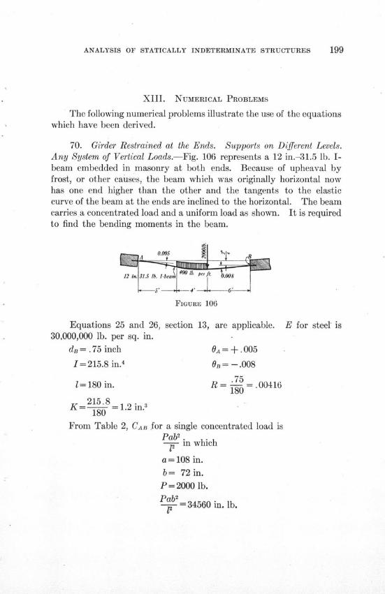
ANALYSIS OF STATICALLY INDETERMINATE STRUCTURES
XIII. NUMERICAL PROBLEMS
The following numerical problems illustrate the use of the equationswhich have been derived.
70. Girder Restrained at the Ends. Supports on Different Levels.Any System of Vertical Loads.-Fig. 106 represents a 12 in.-31.5 lb. I-beam embedded in masonry at both ends. Because of upheaval byfrost, or other causes, the beam which was originally horizontal nowhas one end higher than the other and the tangents to the elasticcurve of the beam at the ends are inclined to the horizontal. The beamcarries a concentrated load and a uniform load as shown. It is requiredto find the bending moments in the beam.
12 in. 31. b. l-beam f & . S
FIGURE 106
Equations 25 and 26, section 13, are applicable. E for steel' is30,000,000 lb. per sq. in.
dB=.75 inch OA= +.005
I= 215.8 in.4 OB = -. 008
751= 180 in. R -- =. 00416
180215.8
KA= 258 = 1.2 in.'180
From Table 2, CAB for a single concentrated load isPab2
-- in which
a = 108 in.
b= 72 in.
P= 2000 lb.
Pab2 34560 in. lb.

ILLINOIS ENGINEERING EXPERIMENT STATION
Also from Table 2, CAB for a uniform load over a portion of the
span is -2- d3 (41-3d)-b(41 - 3b) in which
d = 120 in.
b= 72 in.
400w=400 lb. per ft. = -0-•lb. per in.
122 d3(41- 3d) - b(4- 3b) =37,200 in. lb.
Total CAB = 37,200+34,560 = 71,760 in. lb.
Substituting the values of the constants in equation 25, section 13,gives
MAB= -826,300 in. lb.
From Table 2, CBA for the concentrated load is 52,000 in. lb., andCBA for the uniform load is 32,700 in. lb.
Total CBA=52,000+32,700=84,700 in. lb.Substituting the values of the constants in equation 26, section 13,
gives
MBA= -1,606,300 in. lb.
It is to be noted in the solution of this problem, in solving for bothMAB and MBA, that OA and R are both positive whereas OB is negative.The minus sign, moreover, is used before CAB and the plus sign is usedbefore CBA. The signs are in accordance with the conventional methodof fixing signs given at the bottom of Table 1.
If the supports had been on the same level and if the tangents tothe elastic curves at the ends of the beams had been horizontal, themoments would have been given by the equations of section 11. Usingthe same values of CAB and CBA as before
MAB = -CAB= -71,760 in. lb.MBA = +CBA = +84,700 in. lb.
71. Girder Continuous over Four Supports. Supports on DifferentLevels. Any System of Vertical Loads.-Fig. 107 represents a 20 in.-80 lb. I-beam supported on four supports and having hinged ends.The supports are all on different levels. It is required to find themoments in the girder.
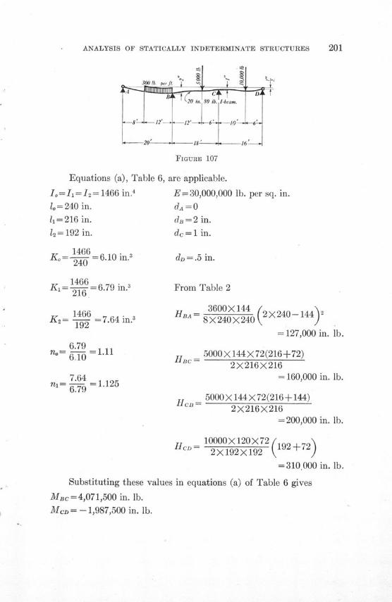
ANALYSIS OF STATICALLY INDETERMINATE STRUCTURES
FIGURE 107
Equations (a), Table 6, are applicable.
Io=I = 12= 1466 in.4 E =30,000,000 lb. per sq. in.lo= 240 in. dA = 011=216 in. da =2 in.
12= 192 in. dc= 1 in.
1466Ko = = 6.10 in. dD= .5 in.
1466K,= - = 6.79 in?. From Table 2
216
1466Ks = 7.64 in
192
6.79n = 1.11n= 610
7.64= I7=1.125
HBA= 3600X 144 (2X240-144) 28 X 240 X240
= 127,000 in. lb.
5000X144X72(216+72)2 X 216 X 216
= 160,000 in. lb.
5000X 144X72(216+144)2X216X216
=200,000 in. lb.
H C D= 10000X120X72 ( 19 2 + 7 2)
=310,000 in. lb.
Substituting these values in equations (a) of Table 6 gives
MBc =4,071,500 in. lb.
MCD = -- 1,987,500 in. lb.
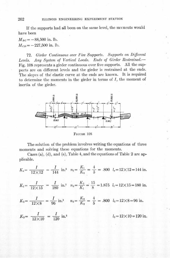
ILLINOIS ENGINEERING EXPERIMENT STATION
If the supports had all been on the same level, the moments wouldhave been
MBC= -88,500 in. lb.
Mn = -227,500 in. lb.
72. Girder Continuous over Five Supports. Supports on Different
Levels. Any System of Vertical Loads. Ends of Girder Restrained.-Fig. 108 represents a girder continuous over five supports. All the sup-ports are on different levels and the girder is restrained at the ends.The slopes of the elastic curve at the ends are known. It is requiredto determine the moments in the girder in terms of I, the moment ofinertia of the girder.
FIGURE 108
The solution of the problem involves writing the equations of threemoments and solving these equations for the moments.
Cases (a), (d), and (e), Table 4, and the equations of Table 2 are ap-plicable.
I I Ki 4Ko= 12X12n = 144 i n 3 ni= = - = .80012 X- 12 n44 K0
I I n.12X15 180
I I .Ks= = in.312X8 96
K - in.3
K 12X10 120
lo= 12X12 = 144 in.
n= 2 _ - ==1.875 11 = 12X15 =180 in.=K-t 8
K3 4n3= = - =.800
K2 5 12=12X8=96 in.
3 = 12X 10= 120 ir,
ANALYSIS OF STATICALLY INDETERMINATE STRUCTURES 203
dA = 2.5 in. dB - dA = 2.8-2.5 = +0.3 in. OA = +.003
dB= 2.8 in. dc-dB=3.0-2.8=+0.2 in. OE=-.002
dc= 3.0 in. dD -dc =3.1-3.0 = +0.1 in. E= 30,000,000 lb. per sq. in.
dD l=3.1 in. dE-dD =3.0-3.1 -0.1 in.
dE = 3.0 in.
HAB= 5000X5X7X19X12 + 12000(16) X (2 X144 -16)2X144 8X144
= -183,900 in. lb.
HBA= 5000X5X7X17X12 12000 144-64 2X144-144-642X144 +8 X 144)
= 190,700 in. lb.
10000X8X7X22X12 12000HBC= 2 2+ > X225=665,500 in. lb.
2X225 8
10000X8X7X23X12 12000 X225681,500 in. b.HcB= 2 X+2 - X 225 = 681,500 in. lb.
2X225 8
HCD= 61 2 00 0 X 64- 3 6 2X64-36-64 =18,400 in. lb.
HDc= 12000 (4) 2X64-4 =11,600 in. Ib.
S10000X5X5(15) X12HDE2= X100 = 225,000 in. lb.
10000X5X5(15) X12HED 200 = 225,000 in. lb.
Substituting the values of these quantities in the equations ofTable 4 gives
From equation (d)
6.4 MBc+2.0 MCD= 1030 I-2,978,000 . . . . . . (786)
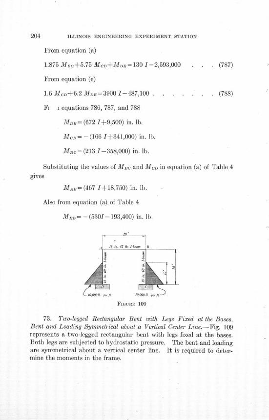
ILLINOIS ENGINEERING EXPERIMENT STATION
From equation (a)
1.875 MBc+5.75 McD+MDE= 130 1-2,593,000 . . . (787)
From equation (e)
1.6 McD+6.2 MD =3900 1-487,100 . . . . . . . (788)
Fi i equations 786, 787, and 788
MDE = (672 1+9,500) in. lb.
Mcn= - (166 1+341,000) in. lb.
Mac= (213 1-358,000) in. lb.
Substituting the values of MBc and Mc. in equation (a) of Table 4
gives
MAB= (467 1+18,750) in. lb.
Also from equation (a) of Table 4
MED = -(53017- 193,400) in. lb.
FIGURE 109
73. Two-legged Rectangular Bent with Legs Fixed at the Bases.Bent and Loading Symmetrical about a Vertical Center Line.-Fig. 109represents a two-legged rectangular bent with legs fixed at the bases.Both legs are subjected to hydrostatic pressure. The bent and loadingare symmetrical about a vertical center line. It is required to deter-mine the moments in the frame.
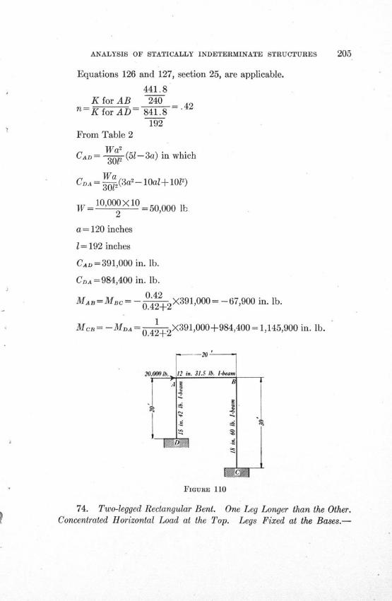
ANALYSIS OF STATICALLY INDETERMINATE STRUCTURES 205
Equations 126 and 127, section 25, are applicable.
441.8K for AB 240
n=K for AD= 841.8192
From Table 2
Wa2
CAD= --- (51-3a) in which
WaCDA = 3 1 (3a- lOal+ 101)
10,000 X 102 =50,000 lb
a= 120 inches
1= 192 inches
CAD= 391,000 in. lb.
CDA= 984,400 in. lb.
0.42MAD =Mac= -- 2 X391,000= -67,900 in. lb.
0.42+2
1McB= -MDA= X391,000+984,400 = 1,145,900 in. lb.0.42+2
FIGURE 110
74. Two-legged Rectangular Bent. One Leg Longer than the Other.Concentrated Horizontal Load at the Top. Legs Fixed at the Bases.-
ILLINOIS ENGINEERING EXPERIMENT STATION
Fig. 110 represents a rectangular bent having one leg longer than theother. There is a horizontal force of 20,000 lb. applied at the top.The bases of the legs are fixed. It is required to determine the momentsin the bent.
Equations 252, 253, 254, and 255, section 33, are applicable.
P= 20,000 lb.
1= 240 inches
h= 240 inches
240q = -=0.667
K for AB = 15 = 0.90 in. 3
240
441.8K for AD= 44 = 1.84 in240
K for BC= 841"8 =2.34 in360
K for ABK for AD=0.49
K for ABs= =0.385
K for BC
Ao= 2(3X.49X .385X .385+4 X.49X.385+.385X.385+.385+3X.49 X.385 X.667+ 3 X.49 X.49 X.385 X .667 X.667+ .49X.49 X.667 X.667+.49 X.667 X.667+4 X.49 X.385 X.667X .667) = 5.334
Substituting the values of the quantities in equations 252, 253,254, and 255, of section 33, gives
MAB= 1,100,000 in. lb.
MBA = 958,000 in. lb.
MDa = -- 1,950,000 in. lb.
Mc= - 1,664,000 in. lb.
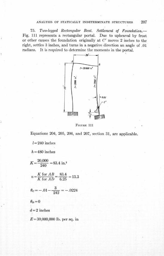
ANALYSIS OF STATICALLY INDETERMINATE STRUCTURES
75. Two-legged Rectangular Bent. Settlement of Foundation.-Fig. 111 represents a rectangular portal. Due to upheaval by frostor other causes the foundation originally at C' moves 2 inches to theright, settles 3 inches, and turns in a negative direction an angle of .01radians. It is required to determine the moments in the portal.
FIGURE 111
Equations 204, 205, 206, and 207, section 31, are applicable.
1= 240 inches
h = 480 inches
K= 20,000 = 83.4 in.3240
K for AB 83.4n=- _ = 13.3K for AD 6.25
3Oc= -. 01- = -. 0224242
0D= 0
d=2 inches
E= 30,000,000 lb. per sq. in
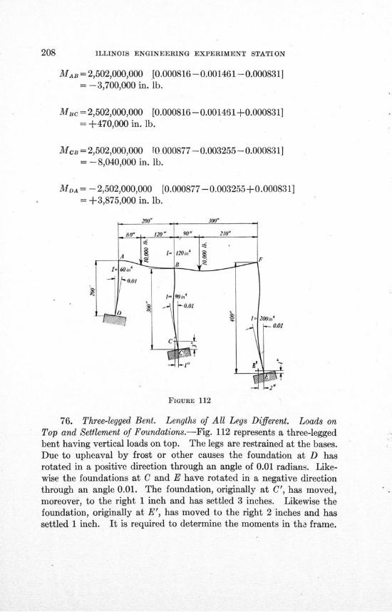
ILLINOIS ENGINEERING EXPERIMENT STATION
MAB = 2,502,000,000 [0.000816-0.001461-0.000831]= -3,700,000 in. lb.
Mc = 2,502,000,000 [0.000816-0.001461+0.000831]= +470,000 in. lb.
Mca = 2,502,000,000 [0 000877 - 0.003255 - 0.000831]= -8,040,000 in. lb.
MDA= -2,502,000,000 [0.000877 -0.003255+0.000831]
= +3,875,000 in. lb.
FIGURE 112
76. Three-legged Bent. Lengths of All Legs Different. Loads onTop and Settlement of Foundations.-Fig. 112 represents a three-leggedbent having vertical loads on top. The legs are restrained at the bases.Due to upheaval by frost or other causes the foundation at D hasrotated in a positive direction through an angle of 0.01 radians. Like-wise the foundations at C and E have rotated in a negative directionthrough an angle 0.01. The foundation, originally at C', has moved,moreover, to the right 1 inch and has settled 3 inches. Likewise thefoundation, originally at E', has moved to the right 2 inches and hassettled 1 inch. It is required to determine the moments in tha frame.
ANALYSIS OF STATICALLY INDETERMINATE STRUCTURES
The equations of Table 21 are applicable. Since there are no hori-zontal loads on the legs nor external couples at the top, Cases IX, X,and XII will not enter.
The total right-hand members of the equations of Table 21 willtherefore be the algebraic sum of the right-hand members due to CaseVII, Case VIII, and Case XI.
ho= 200 in.
h2 = 300 in.
h4=400 in.
1, = 200 in.
13= 300 in.
Ko= 0.30 in.'
K1 = 0.60 in.3
K2 = 0.30 in.
K 3 = 0.40 in.3
K4 =0.50 in.3
6dK 1 6X3X0.6 .-= 20 = 0.054 in.311 200
6d 2K2 _ 6X1X0.3S 300 = 0.006 in.3
h, 300
Io= 60 in.4
It= 120 in. 4
12 =90 in.4
13=120 in. 4
14=200 in. 4
CA, = 2,880,000 in. lb.
CBA = 1,920,000 in. lb.
CBF = 4,410,000 in. lb.
CB = 1,890,000 in. lb.
E =30,000,000 lb. per sq. in.
Ko0 = 0.003 in.3
K 20c =- 0.003 in.3
K4OE = -0.005 in.3
6(d 3-d 1 )Ks _ 6X(-2)X0.413 300
= -0.016 in.3
6d 4K 4 6X2X0.5 =0.015 n.= = '0.015 in.3
h4 - 400
Substituting the values of these quantities in the equations ofTable 23 gives equations 1, 2, 3, and 4 of Table 32. It is to be notedin the equations of Table 32 that the quantities under the headings
100Case VII and Case VIII are coefficients of E-- - Solving equations 1,
2, 3, and 4 by the method of elimination, as given in Table 32, gives
d= - [49,373,300-19,722,1001 +1.19314
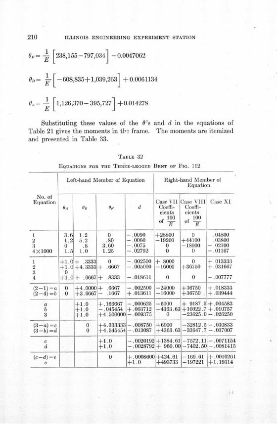
ILLINOIS ENGINEERING EXPERIMENT STATION
6= [238,155-797,034] -0.0047062
On= 0 - [-608,835+1,039,263 -+0.0061134
06,= - 1 1,126,370- 395,727 +0.014278E
Substituting these values of the O'sTable 21 gives the moments in th" frame.and presented in Table 33.
and d in the equations ofThe moments are itemized
TABLE 32
EQUATIONS FOR THE THREE-LEGGED BENT OF FIG. 112
Left-hand Member of Equation Right-hand Member ofEquation
No. ofEquation Case VII Case VIII Case XI
OA OB op d Coeffi- Coeffi-cients cients
100 100of -- of 0-
1 3.6 1.2 0 --. 0090 +28800 0 .048002 1.2 5.2 .80 -. 0060 -19200 +44100 .038003 0 .8 3.60 --. 0075 0 -18900 --. 021004X1000 1.5 1.0 1.25 -. 02792 0 0 -. 01167
1 +-1.0 + .3333 0 -. 002500 + 8000 0 +.0133332 +1.0+4.3333 + .6667 -. 005000 -16000 +36750 +.0316673 04 +1.0 + .6667 + .8333 -. 018611 0 0 -. 007777
(2--1) =a 0 +4.0000 + .6667 -. 002500 -24000 +36750 +.018333(2-4) =b 0 +3.6667 - .1667 +.013611 -16000 +36750 . 4039444
a +1.0 +.166667 -. 000625 -6000 + 9187.5 +.004583b +1.0 -. 045454 +.003712 -4363.63 +10022.7 +.0107573 +1.0 +4.500000 -. 009375 0 -23625.0 - .026250
(3-a) =c 0 +4.333333 -. 008750 +6000 -32812.5 -. 030833(3--b)=d 0 +4.545454 - .013087 +4363.63 -33647.7 -. 037007
c +1.0 -. 0020192 +1384.61 -7572.11 -. 0071154d +1.0 -. 0028792 + 960.00 -7402.50 --. 0081415
(c-d) =e 0 +.0008600+424.61 -169.61 +.0010261e +1.0 +493733 -197221 +1.19314
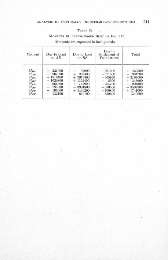
ANALYSIS OF STATICALLY INDETERMINATE STRUCTURES
TABLE 33
MOMENTS IN THREE-LEGGED BENT OF FIG. 112
Moments are expressed in inch-pounds.
Due toMoment Due to Load Due to Load Settlement of Total
on AB on BF Foundations
MDA + 231500 - 59900 +294900 + 466500MAB - 907300 + 297400 -371800 - 981700MBA + 1810400 + 2019400 -665800 + 3164000MBC - 1026800 + 1365400 + 5300 + 343900MCB - 661500 + 741900 -284700 - 204300MBF - 783600 - 3384800 +660500 - 3507900MFB - 106000 + 1446200 +400800 + 1741000MEF - 132100 - 649100 0 -559600 - 1340800
ILLINOIS ENGINEERING EXPERIMENT STATION
XIV. CONCLUSIONS
Some outstanding features of the use of the slope-deflection equa-tions, as brought out by the analysis in Part II, may well be emphasized.
Two general methods of using the equations have been illustrated.In one case, after the equations have been written for each member ofa frame, by equating the sum of the moments at each joint to zero andemploying one equation of statics, a number of equations is obtainedwhich contain values of 0 and R as the only unknowns. From theseequations can be found values of '0 and R, which, when substituted inthe original slope-deflection equations, give values of the variousmoments. This method applies especially well to a frame in whicha large number of members meet at each joint. Such a problem isgenerally best solved in numerical terms. Examples of this methodare found in sections 23, 61, 64, and 65.
The procedure in the other case is more direct. The slope-deflec-tion equations for each member may be combined to eliminate valuesof 0 and R, leaving equations involving the unknown moments, theproperties of the members, and the given loading of the frame. Theseequations may be solved directly for the moments. Examples of thismethod are found in sections 24, 35, and 49.
Special attention is called to the form of the equations, whichare independent of the magnitude and location of the individual loads,except as the magnitude and location of such loads influence the numer-ical values of the quantities C and H of the equations. The quantitiesC and H are determinate and their numerical values may be readilyfound for any known system of loads.
It is well to note also that the treatment of continuous girders forwhich the supports are not on the same level is comparatively simple.This part of the work is of considerable value inasmuch as it permitsthe determination of the effect of the settlement of supports. Thetreatment of the settlement of foundations for two-legged bents is ofequal importance.
Advantages of the slope-deflection equations which are worthy ofappreciation are:
(1) The general form of the fundamental equation is easilymemorized, and the equations may be written for all members ofa structure with little effort. The value of the quantities C or H
ANALYSIS OF STATICALLY INDETERMINATE STRUCTURES
for loaded members may be calculated by reference to Tables 2and 3. It is frequently possible to simplify the equations throughnoting where values of 0 and R must be equal to zero from theconditions of the problem.
(2) No integrations need be performed except possibly tofind values of C or H, and there is little danger of the omission ofthe effect of a single indeterminate quantity, as there is in methodsinvolving the work of internal forces or moments.
(3) The physical conception of a problem is easier than in thecase where differentiation or integration is performed. When theslopes and deflections are determined, it is easy to visualize theapproximate shape of the elastic curve of a member, whereas anexpression involving the work of an indeterminate force or momentmay have little physical meaning. Neither does the method ofcutting a member and equating expressions for the linear andangular movement of the adjoining ends give so clear an idea ofthe actual deformation. To one unfamiliar with such a method,the determination of the sign of the movement of the ends of themember cut is also more or less difficult.
(4) It is shown in sections 67, 68, and 69 that the effect ofaxial and shearing deformations and of slip of joints may be cal-culated by the use of the slope-deflection equations. This makespossible a complete treatment of any problem, though it is shownthat it is seldom necessary to make use of such refinements in ananalysis.
(5) The use of the quantity K for I- of a member, and also
of quantities n, s, and p, as ratios of K's for different members,is of great help in writing equations in a workable form. Therestraint factor N is also useful in simplifying both analyses andfinal equations.
(6) Although the fact has not been brought out in thisbulletin, these equations may be applied to many structures notcomposed of rectangular units. The determination of secondarystresses in bridge trusses is an example of such use which has beenin print for some time. With trapezoidal and triangular frames,care must be taken in the use of the term R for adjoining members.
ILLINOIS ENGINEERING EXPERIMENT STATION
(7) While the method is readily applicable to all theproblems solved in this bulletin, its advantage over other methodsis seen when applied to structures which are statically indeterminateto a high degree and in which a number of members meets at eachjoint.
The use of statically indeterminate structures in recent years hasgrown rapidly and many new types of structures have been evolved.With the use of riveted connections in steel frames and the develop-ment of monolithic reinforced concrete structures of all sorts, it oftenhappens that statically indeterminate stresses cannot be avoided. Onthe other hand, structures are frequently made of an indeterminatetype for the purpose of securing economy of material. Rationalmethods of design will do much to inspire confidence in the reliabilityand economy of such structures, thus insuring their more widespreaduse.
It is felt that the treatment of statically indeterminate structuresgiven in this bulletin will be helpful in giving information regardingsuch structures. The method has been explained in sufficient detailto enable the designing engineer to use it in the solution of his particularproblems. It is believed that the fundamental principles can be quicklyco6rdinated with the ordinary principles of mechanics so that the morecomplex problems and even the simpler ones may be studied from a newviewpoint.
LIST OF
PUBLICATIONS OF THE ENGINEERING EXPERIMENT STATION
Bulletin No. 1. Tests of Reinforced Concrete Beams, by Arthur N. Talbot. 1904. None available.
Circular No. 1. High-Speed Tool Steels, by L. P. Breckenridge. 1905. None available.
Bulletin No. 2. Tests of High-Speed Tool Steels on Cast Iron, by L. P. Breckenridge and HenryB. Dirks. 1905. None available.
Circular No. 2. Drainage of Earth Roads, by Ira 0. Baker. 1906. None available.
Circular No. 3. Fuel Tests with Illinois Coal (Compiled from tests made by the TechnologicalBranch of the U. S. G. S., at the St. Louis, Mo., Fuel Testing Plant, 1904-1907), by L. P. Breckenridgeand Paul Diserens. 1908. Thirty cents.
Bulletin No. 3. The Engineering Experiment Station of the University of Illinois, by L. P.Breckenridge. 1906. None available.
Bulletin No. 4. Tests of Reinforced Concrete Beams, Series of 1905, by Arthur N. Talbot.19006. Forty-five cents.
Bulletin No. 5. Resistance of Tubes to Collapse, by Albert P. Carman and M. L. Carr. 1906.None available.
Bulletin No. 6. Holding Power of Railroad Spikes, by Roy I. Webber. 1906. None available.
Bulletin No. 7. Fuet Tests with Illinois Coals, by L. P. Breckenridge, S. W. Parr, and Henry B.Dirks. 1906. None available.
Bulletin No. 8. Tests of Concrete: I, Shear; II, Bond, by Arthur N. Talbot. 1906. Noneavailable.
Bulletin No. 9. An Extension of the Dewey Decimal System of Classification Applied to theEngineering Industries, by L. P. Breckenridge and G. A. Goodenough. 1906. Revised Edition1912. Fifty cents.
Bulletin No. 10. Tests of Concrete and Reinforced Concrete Columns, Series of 1906, by ArthurN. Talbot. 1907. None available.
Bulletin No. 11. The Effect of Scale on the Transmission of Heat through Locomotive BoilerTubes, by Edward C. Schmidt and John M. Snodgrass. 1907. None available.
Bulletin No. 12. Tests of Reinforced Concrete T-Beams, Series of 1906, by Arthur N. Talbot1907. None available.
Bulletin No. 18. An Extension of the Dewey Decimal System of Classification Applied to Archi-tecture and Building, by N. Clifford Ricker. 1907. None available.
Bulletin No. 14. Tests of Reinforced Concrete Beams, Series of 1906, by Arthur N. Talbot.1907. None available.
Bulletin No. 15. How to Burn Illinois Coal without Smoke, by L. P. Breckenridge. 1908.None available.
Bulletin No. 16. A Study of Roof Trusses, by N. Clifford Ricker. 1908. None available.
Bulletin No. 17. The Weathering of Coal, by S. W. Parr, N. D. Hamilton, and W. F. Wheeler.1908. None available.
Bulletin No 18. The Strength of Chain Links, by G. A. Goodenough and L. E. Moore. 1908.Forty cents.
Bulletin No. 19. Comparative Tests of Carbon, Metallized Carbon and Tanta'um FilamentLamps, by T. H. Amrine. 1908. None available.
Bulletin No. 20. Tests of Concrete and Reinforced Concrete Columns, Series of 1907, by ArthurN. Talbot. 1908. None available.
Bulletin No. 21. Tests of a Liquid Air Plant, by C. S. Hudson and C. M. Garland. 1908. Fifteencents.
Bulletin No. 22. Tests of Cast-Iron and Reinforced Concrete Culvert Pipe, by Arthur N. Talbot.1908. None available.
Bulletin No. 28. Voids, Settlement and Weight of Crushed Stone, by Ira 0. Baker. 1908.Fifteen cents.
*Bulletin No. 24. The Modification of Illinois Coal by Low Temperature Distillation, by S. W. Parrand C. K. Francis. 1908. Thirty cents.
Bulletin No. 25. Lighting Country Homes by Private Electric Plants, by T. H. Amrine. 1908.Twenty cents.
*A limited number of copies of bulletins starred is available for free distribution.
216 PUBLICATIONS OF THE ENGINEERING EXPERIMENT STATION
Bulletin No. 26. High Steam-Pressure in Locomotive Service. A Review of a Report to theCarnegie Institution of Washington, by W. F. M. Goss. 1908. Twenty-five cents.
Bulletin No. 27. Tests of Brick Columns and Terra Cotta Block Columns, by Arthur N. Talbotand Duff A. Abrams,. 1909. Twenty-five cents.
Bulletin No. 28. A Test of Three Large Reinforced Concrete Beams, by Arthur N. Talbot.1909. Fifteen cents.
Bulletin No. 29. Tests of Reinforced Concrete Beams: Resistance to Web Stresses, Series of1907 and 1908, by Arthur N. Talbot. 1909. Forty-five cents.
*Bulletin No. 30. On the Rate of Formation of Carbon Monoxide in Gas Producers, by J. K. Cle-ment, L. H. Adams, and C. N. Haskins. 1909. Twenty-five cents.
*Bulletin No. 81. Tests with House-Heating Boilers, by J. M. Snodgrass. 1909. Fifty-fivecents.
Bulletin No. 32. The Occluded Gases in Coal, by S. W. Parr and Perry Barker. 1909. Fifteencents.
Bulletin No. 3SS. Tests of Tungsten Lamps, by T. H. Amrine and A. Guell. 1909. Twenty cents.
*Bulletin No. 34. Tests of Two Types of Tile-Roof Furnaces under a Water-Tube Boiler, by J. M.Snodgrass. 1909. Fifteen cents.
Bulletin No. 85. A Study of Base and Bearing Plates for Columns and Beams, by N. CliffordRicker. 1909. Twenty cents.
Bulletin No. 36. The Thermal Conductivity of Fire-Clay at High Temp3ratures, by J. K. Clementand W. L. Egy. 1909. Twenty cents.
Bulletin No. 37. Unit Coal and the Composition of Coal Ash, by S. W. Parr and W. F. Wheeler.1909. None available.
Bulletin No. 38. The Weathering of Coal, by S. W. Parr and W. F. Wheeler. 1909. Twenty-five cents.
*Bulletin No. 89. Tests of Washed Grades of Illinois Coal, by C. S. McGovney. 1909. Seventy-five cents.
Bulletin No. 40. A Study in Heat Transmission, by J. K. Clement and C. M. Garland. 1910.Ten cents.
Bulletin No. 41. Tests of Timber Beams, by Arthur N. Talbot. 1910. Thirty-five cents.
*Bulletin No. 42. The Effect of Keyways on the Strength of Shafts, by Herbert F. Moore. 1910.Ten cents.
Bulletin No. 43. Freight Train Resistance, by Edward C. Schmidt. 1910. Seventy-five cents.
Bulletin No. 44. An Investigation of Built-up Columns under Load, by Arthur N. Talbot andHerbert F. Moore. 1911. Thirty-five cents.
*Bulletin No. 45. The Strength of Oxyacetylene Welds in Steel, by Herbert L. Whittemore. 1911.Thirty-five cents.
*Bulletin No. 46. The Spontaneous Combustion of Coal, by S. W. Parr and F. W. Kressman.1911. Forty-five cents.
*Bulletin No. 47. Magnetic Properties of Heusler Alloys, by Edward B. Stephenson, 1911. Twen-ty-five cents.
*Bulletin No. 48. Resistance to Flow through Locomotive Water Columns, by Arthur N. Talbotand Melvin L. Enger. 1911. Forty cents.
*Bulletin A ,. 49. Tests of Nickel-Steel Riveted Joints, b Arthur N. Talbot and Herbert F. Moore.1911. Thirty cents.
*Bulletin No. 50. Tests of a Suction Gas Producer, by C. M. Garland and A. P. Kratz. 1912.Fifty cents.
Bulletin No. 51. Street Lighting, by J. M. Bryant and H. G. Hake. 1912. Thirty-five cents.
*Bulletin No. 52. An Investigation of the Strength of Rolled Zinc, by Herbert F. Moore. 1912.Fifteen cents.
*Bulletin No. 53. Inductance of Coils, by Morgan Brooks and H. M. Turner. 1912. Forty cents.
*Bulletin No. 54. Mechanical Stresses in Transmission Lines, by A. Guell. 1912. Twenty cents.
*Bulletin No. S5. Starting Currents of Transformers, with Special Reference to Transformers withSilicon Steel Cores, by Trygve D. Yensen. 1912. Twenty cents.
*Bulletin No. 56. Tests of Columns:- An Investigation of the Value of Concrete as Reinforcementfor Structural Steel Columns, by Arthur N. Talbot and Arthur R. Lord. 1912. Twenty-five cents.
*Bulletin No. 57. Superheated Steam in Locomotive Service. A Review of Publication No. 127of the Carnegie Institution of Washington, by W. F. M. Goss. 1912. Forty cents.
*A limited number of copies of bulletins starred is available for free distribution.
PUBLICATIONS OF THE ENGINEERING EXPERIMENT STATION 217
*Bulletin No. 58. A New Analysis of the Cylinder Performance of Reciprocating Engines, byJ. Paul Clayton. 1912. Sixty cents.
*Bulletin No. 59. The Effect of Cold Weather upon Train Resistance and Tonnage Rating, byEdward C. Schmidt and F. W. Marquis. 1912. Twenty cents.
Bulletin No. 60. The Coking of Coal at Low Temperatures, with a Preliminary Study of theBy-Products, by S. W. Parr and H. L. Olin. 1912. Twenty-five cents.
*Bulletin No. 61. Characteristics and Limitation of the Series Transformer, by A. R. Andersonand H. R. Woodrow. 1913. Twenty-five cents.
Bulletin No. 62. The Electron Theory of Magnetism, by Elmer H. Williams. 1913. Thirty-fivecents.
Bulletin No. 63. Entropy-Temperature and Transmission Diagrams for Air, by C. R. Richards.1913. Twenty-five cents.
*Bulletin No. 64. Tests of Reinforced Concrete Buildings under Load, by Arthur N. Talbot andWillis A. Slater. 1913. Fifty cents.
*Bulletin No. 65. The Steam Consumption of Locomotive Engines from the Indicator Diagrams,by J. Paul Clayton. 1913. Forty cents.
Bulletin No. 66. The Properties of Saturated and Superheated Ammonia Vapor, by G. A. Good-enough and William Earl Mosher. 1913. Fifty cents.
Bulletin No. 67. Reinforced Concrete Wall Footings and Column Footings, by Arthur N. Talbot.1913. Fifty cents.
Bulletin No. 68. The Strength of I-Beams in Flexure, by Herbert F. Moore. 1913. Twentycents.
Bulletin No. 69. Coal Washing in Illinois, by F. C. Lincoln. 1913. Fifty cents.
Bulletin No. 70. The Mortar-Making Qualities of Illinois Sands, by C. C. Wiley. 1913. Twentycents.
Bulletin No. 71. Tests of Bond between Concrete and Steel, by Duff A. Abrams. 1914. Onedollar.
*Bulletin No. 72. Magnetic and Other Properties of Electrolytic Iron Melted in Vacuo, by TrygveD. Yensen. 1914. Forty cents.
Bulletin No. 73. Acoustics of Auditoriums, by F. R. Watson. 1914. Twenty cents.
*Bulletin No. 74. The Tractive Resistance of a 28-Ton Electric Car, by Harold H. Dunn. 1914.Twenty-five cents.
Bulletin No. 75. Thermal Properties of Steam, by G. A. Goodenough. 1914. Thirty-five cents.
Bulletin No. 76. The Analysis of Coal with Phenol as a Solvent, by S. W. Parr and H. F. Hadley.1914. Twenty-five cents.
*Bulletin No. 77. The Effect of Boron upon the Magnetic and Other Properties of ElectrolyticIron Melted in Vacuo, by Trygve D. Yensen. 1915. Ten cents.
*Bulletin No. 78. A Study of Boiler Losses, by A. P. Kratz. 1915. Thirty-five cents.
*Bulletin No. 79. The Coking of Coal at Low Temperatures, with Special Reference to the Prop-erties and Composition of the Products, by S. W. Parr and H. L. Olin. 1915. Twenty-five cents.
Bulletin No. 80. Wind Stresses in the Steel Frames of Office Buildings, by W. M. Wilson andG. A. Maney. 1915. Fifty cents.
*Bulletin No. 81. Influence of Temperature on the Strength of Concrete, by A. B. McDaniel.1915. Fifteen cents.
Bulletin No. 82. Laboratory Tests of a Consolidation Locomotive, by E. C. Schmidt, J. M. Snod-grass, and R. B. Keller. 1915. Sixty-five cents.
*Bulletin No. 83. Magnetic and Other Properties of Iron Silicon Alloys. Melted in Vacuo, byTrygve D. Yensen. 1915. Thirty-five cents.
Bulletin No. 84. Tests of Reinforced Concrete Flat Slab Structures, by Arthur N. Talbot andW. A. Slater. 1916. Sixty-five cents.
*Bulletin No. 85. The Strength and Stiffness of Steel under Biaxial Loading, by A. T. Becker.1916. Thirty-five cents.
*Bulletin No. 86. The Strength of I-Beams and Girders, by Herbert F. Moore and W. M. Wilson.1916. Thirty cents.
*Bulletin No. 87. Correction of Echoes in the Auditorium, University of Illinois, by F. R. Watsonand J. M. White. 1916. Fifteen cents.
Bulletin No. 88. Dry Preparation of Bituminous Coal at Illinois Mines, by E. A. Holbrook. 1916.Seventy cents.
*A limited number of copies of bulletins starred is available for free distribution.
218 PUBLICATIONS OF THE ENGINEERING EXPERIMENT STATION
*Bulletin No. 89. Specific Gravity Studies of Illinois Coal, by Merle L. Nebel. 1916. Thirtycents.
*Bulletin No. 90. Some Graphical Solutions of Electric Railway Problems, by A. M. Buck.1916. Twenty cents.
Bulletin No. 91. Subsidence Resulting from Mining, by L. E. Young and H. H. Stoek. 1916.None available.
*Bulletin No. 92. The Tractive Resistance on Curves of a 28-Ton Electric Car, by E. C. Schmidtand H. H. Dunn. 1916. Twenty-five cents.
*Bulletin No. 93. A Preliminary Study of the Alloys of Chromium, Copper, and Nickel, byD. F. McFarland and 0. E. Harder. 1916. Thirty cents.
*Bulletin No. 94. The Embrittling Action of Sodium Hydroxide on Soft Steel, by S. W. Parr.1917. Thirty cents.
*Bulletin No. 95. Magnetic and Other Properties of Iron-Aluminum Alloys Melted in Vacuo, byT. D. Yensen and W. A. Gatward. 1917. Twenty-five cents.
*Bulletin No. 96. The Effect of Mouthpieces on the Flow of Water through a Submerged ShortPipe, by Fred B Seely. 1917. Twenty-five cents.
Bulletin No. 97. Effects of Storage upon the Properties of Coal, by S. W. Parr. 1917. Twentycents.
*Bulletin No. 98. Tests of Oxyacetylene Welded Joints in Steel Plates, by Herbert F. Moore.1917. Tea cents.
Circular No. 4. The Economical Purchase and Use of Coal for Heating Homes, with SpecialReference to Conditions in Illinois. 1917. Ten cents.
*Bulletin No. 99. The Collapse of Short Thin Tubes, by A. P. Carman. 1917. Twenty cents.
*Circular No. 5. The Utilization of Pyrite Occurring in Illinois Bituminous Coal, by E. A.Holbrook. 1917. Twenty cents.
*Bulletin No. 100. Percentage of Extraction of Bituminous Coal with Special Reference to IllinoisConditions, by C. M. Young. 1917.
*Bulletin No. 101. Comparative Tests of Six Sizes of Illinois Coal on a Mikado Locomotive, byE. C. Schmidt, J. M. Snodgrass, and 0. S. Beyer, Jr. 1917. Fifty cents.
*Bulletin No. 10W. A Study of the Heat Transmission of Building Materials, by A. C. Willardand L. C. Lichty. 1917. Twenty-five cents.
*Bulletin No. 108. An Investigation of Twist Drills, by B. Benedict and W. P. Lukens. 1917.Sixty cents.
*Bulletin No. 104. Tests to Determine the Rigidity of Riveted Joints of Steel Structures byW. M. Wilson and H. F. Moore. 1917. Twenty-five cents.
Circular No. 6. The Storage of Bituminous Coal, by H. H. Stoek. 1918. Forty cents.
Circular No. 7. Fuel Economy in the Operation of Hand Fired Power Plants. 1918. Twentycents.
*Bulletin No. 105. Hydraulic Experiments with Valves, Orifices, Hose, Nozzles, and OrificeBuckets, by Arthur N. Talbot, Fred B Seely, Virgil R. Fleming and Melvin L. Enger. 1918.Thirty-five cents.
*BulletinNo. 106. Test of a Flat Slab Floor of the Western Newspaper Union Building, byArthur N. Talbot and Harrison F. Gonnerman. 1918. Twenty cents.
Circular No. 8. The Economical Use of Coal in Railway Locomotives. 1918. Twenty cents.
*Bulletin No. 107. Analysis and Tests of Rigidly Connected Reinforced Concrete Frames, byMNikishi Abe. 1918. Fifty cents.
*Bulletin No. 108. Analysis of Statically Indeterminate Structures by the Slope Deflection Method,by W. M. Wilson, F. E. Richart and Camillo Weiss. 1918. One dollar.
*A limited number of copies of bulletins btarred is available for free distribution,
THItJ UNIVERSITY OF ILLINOIS
THE STATE UNIVERSITY
Urbana
EDMUND J. JAMtES, Ph. D., LL. D., President
THE UNIVERSITY INCLUDES THE FOLLOWING DEPARTMENTS,
The Graduate School
The College of Liberal Art& and Sciences (Ancient and Modern Languages and,Literatures; History, Economics, Political Science, Sociology; Philosophy;Psychology, Education; Mathematics; Astronomy; Geology; Physics; Chemiistry,Botany, Zoology, Entomology; Physiology; Art and Design)
The College of Commerce and Business Administration (General Business, Bank-ing, Insurance, Accountancy, Railway Administration, Poreign Commerce;Courses for Commercial Teachers and Cnommercial and Civic Secretaries)
The College of Euineering (Architecture; Arhitectural, Ceramic, Civil, Electrical,Mechanical, M ing, Municipal and Sanitary, and Railway Engineering)
The College of Agriculture (Agronomy; Animal Husbandry; Dairy Husbandry;Horticulture and Landscape Gardening; Agricultural Extension; Teachers'Course; Household Science)
The College of Law (three years' course)
The School of Education
The Course in JournalismThe Courses in Chemistry and Chemical Engineering
The School of Railway Eniigineering and Administration
The School of Music (four years' course)
The School of Library Sciente (two years' course)
The College of Medicine (in Chicago)The College of Dentistry (in Chicago)
The School of Pharmacy (in Chicago -Ph. G. and Ph. C. courses)
The Summer Session (eight weeks)Experiment Stations' and Scientifle Bureaus; U. S. Agricultural Experiment
Station; Engineering Experiment Station; State LIaboratoiry of Natural His-tory; State Entomologist's Office; Blogicat Experiment StAtion on IllioiasRiver; State Water Survey: State Geologial urvey; U. S. Bureau of MinesExperiment Station.
The r ey ections contaia (Noverber i, t98) 437,949 volumes and 108,28 9parplets.
For catalogs and information address
THE REGM8'IRAR
$(-TJ ANA, LLN*rS
'w '\ ^ ^ *" "1'; "* .
:^
; '" ." r^ :''* ' -
11*1
,. "" ^ s "'.1' ^^ ^'^ w-o AHA K .'',.^ 11 1
''-;.^ .; ^ '.A -- tf ;''
^l^ ^^^'^
4
at. '~:
A
A'."'
'A -
A>
"5 '
A 4' A -
IA,
4 4r> 4 A
At'5' 4' s'
-~ 4 '5--"
A -
A' -J A "A' 'A'A» A~ ~ A',
SF'
4 s T'~ 'A51 )' A AJ"JA "'K A> 4 4.
t>. A ' N"47"- 4' 'A p'>'A
A> 'K r i t ';"r<' 'A'AA 4"~A"~ A'"A> * #~' - '4
"~ ~> A>"' -5-5
A> '4]"'* -s '>' 4½ 4'' "4 '0<
-' >'A"4
) t"A4' A > ~' '"~r'<,Q"'"V~%'\ A AA 1>t''',> ;rk'A'5' 1" 'K A"
~ "<½"'' t"' ~5". K> Z~%-At~.AA~&A'K ;"' "A'
"AA' -"
A',
- A''"t,,'5'> ,'5" ""A" - rA ''', -
4'
~ 'KA' 4'
A
S'N
''1
A
4> k
\i-' a"*
I
t~ At'
A''
"'A•~!•~i ,
'<A 'A
"5 ,"
A N
.1
'4 A
""'N-½'5<A>
A A.
'1,1 4
'I
5' ' r'4'< A
A''
'A-""A A' A
'A' ,
KA A%[ A
A"
-^N.
;.- -i i, -F.. ._
^ -.*,-;'^.. ̂ " ''^ ;"
,'* -".': - *'«$' -' ,* '* *'

![Slope Deflection Method[1]](https://static.fdocuments.in/doc/165x107/5571fe4449795991699b02b5/slope-deflection-method1.jpg)