
SLO-SPEED WORM GEAR REDUCER INSTRUCTIONS … · 2000RA WORM GEAR REDUCER ... safety codes in his...
22
2000RA WORM GEAR REDUCER INSTALLATION AND MAINTENANCE MANUAL January 22, 2018
Transcript of SLO-SPEED WORM GEAR REDUCER INSTRUCTIONS … · 2000RA WORM GEAR REDUCER ... safety codes in his...

2000RA
WORM GEAR REDUCER
INSTALLATION AND MAINTENANCE MANUAL January 22, 2018

- 2 - 2
7997 Allison Avenue, Indianapolis, IN 46268 Website: www.sterlingelectric.com
(800) 866-7973 FAX (317) 872-0907 email:[email protected]
2000RA WORM GEAR REDUCER INSTRUCTION MANUAL
SELECTION INFORMATION
Read ALL instructions prior to operating reducer. Improper maintenance or operation may cause injury to personnel or reducer failure. Written authorization from Sterling Electric is required to operate or use reducers in man lift or people moving devices. Check to make certain application does not exceed the allowable load capacities published in the current catalog. Buyer shall be solely responsible for determining the adequacy of the product for any and all uses to which buyer shall apply the product. The application by buyer shall not be subject to any implied warranty of fitness for a particular purpose. Information contained in this manual is considered correct at the time of publication and is subject to change without notice.
SAFETY ALERT WARNING: For safety, purchaser or user should provide protective guards over all shaft extensions and
any moving apparatus mounted thereon. The user is responsible for checking all applicable safety codes in his area and providing suitable guards. Failure to do so may result in bodily injury and/or damage to equipment.
WARNING: Lifting devices that may be supplied with reducers are for lifting and placing the reducer
only. Do not use lifting devices to lift any other objects or additional weight such as motors, pumps, skids, etc. Using lifting devices to lift other objects or additional weight may cause lifting devices to fail and resulting in death, serious personal injury or property damage.
WARNING: Hot oil or reducers can cause severe burns. Use extreme care when removing lubrication
plugs and vents. WARNING: Make certain that the power supply is disconnected before attempting to service or remove
any components. Lock out the power supply and tag it to prevent unexpected application of power.
WARNING: Reducers are not to be considered fail safe or self-locking devices. If these features are
required, a properly sized, independent holding device should be utilized. WARNING: Any brakes that are used in conjunction with a reducer must be sized or positioned in such a
way as to not subject the reducer to loads beyond the catalog rating. CAUTION: Test run unit to verify operation. If the unit tested is a prototype, that unit must be of current
production. CAUTION: If the speed reducer cannot be located in a clear and dry area with access to adequate cooling
air supply, then precautions must be taken to avoid the ingestion of contaminants such as water and the reduction in cooling ability due to exterior contaminants. Reducers located in confined spaces may require forced air-cooling.
- 3 - 3
IMPORTANT INFORMATION In the event of the resale of any of the goods, in whatever form, Resellers/Buyers will include the following language in a conspicuous place and in a conspicuous manner in a written agreement covering such sale: The manufacturer makes no warranty or representations, expressed or implied, by
operation of law or otherwise, as to the merchantability or fitness for a particular purpose of the good sold hereunder. Buyer acknowledges that it alone has determined that the goods purchased hereunder will suitably meet the requirements of their intended use. In no event will manufacturer be liable for consequential, incidental or other damages.
Resellers/Buyers agree to also include this entire document including the warnings above in a conspicuous place and in a conspicuous manner in writing to instruct users on the safe usage of the product. This instruction manual should be read together with all other printed information such as catalogs, supplied by Sterling Electric.
GENERAL OPERATION 1. Run the motor, which drives the reducer, and check the direction of reducer output rotation. Consult
motor nameplates for instructions to reverse the direction of rotation. 2. Attaching the load: On direct-coupled installations, check shaft and coupling alignment between speed
reducer and loading mechanism. On chain/sprocket and belt/pulley installation, locate the sprocket or pulley as close to the oil seal as possible to minimize overhung load. Check to verify that the overhung load does not exceed specifications published in the catalog.
3. High momentum loads: If coasting to a stop is undesirable, a braking mechanism should be provided to
the speed reducer output or the driven mechanism.
CAUTION: The system of connected rotating parts must be free from critical speed, torsional or other type vibration, no matter how induced. The responsibility for this system analysis lies with the purchaser of the speed reducer.
RUN-IN PERIOD
The maximum efficiency of worm reducers is obtained after a “Run-In” period. The length of time required will depend on the load applied and may be two to four hours at rated load and will be considerably longer at lighter loads. Overloading will not decrease the “Run-In” time but will cause severe wear and damage to the unit. During “Run-In”, higher than normal motor current and temperatures along with lower efficiency and output torque can be expected.
SELF-LOCKING ABILITY Under no condition should Sterling Electric, Inc. worm gear reducers be considered to hold a load at rest. The statement is made to cover the broad spectrum of variables effecting self-locking characteristics of a particular gear set in a particular application. Theoretically, a worm gear will not back drive if the friction angle is greater than the worm lead angle. However, the actual surface finish and lubrication may reduce this significantly. More important, vibration may cause motion at the point of mesh with further reduction in friction angle. No guarantee should be made and the customer should be advised that if these features are required, a properly sized, independent holding device, such as a brake, should be utilized in order to maintain a safe working environment. Sterling Electric, Inc. cannot accept liability for any damage to personnel or property that may occur from the application of worm gear reducers in which the self-locking ability is utilized to hold a load.
- 4 - 4
INSTALLATION-FOOT MOUNT
1. Mount the unit to a rigid flat surface using grade 5 or higher fasteners. The mounting fasteners should
be the largest standard size that will fit in the base mounting hole. Shim as required under flange or base feet that do not lie flat against the mounting surface.
2. Connect motor to speed reducer.
INSTALLATION – SHAFT MOUNT
1. Clean driven shaft extension and output bore of the unit. 2. Apply anti-seize or anti-fretting compound (not supplied) to the hollow bore of the unit to aid
removal at a later date. 3. Locate the unit in position onto the driven shaft by the most convenient method using good
engineering practices; ensuring it is as close as possible to the bearing on the driven equipment. 4. Anchor the unit to a secure point on the structure by means of the torque arm or other flexible
device.
WARNING: DO NOT RIGID MOUNT UNIT. Mounting should be such to allow freedom of movement of the reducer to pivot around the driven shaft centerline without imposing excessive loads than can lead to driven shaft breakage, premature reducer bearing failure, cracking of the conveyor structure, and leaks. Consult factory if needed.
5. Fit guards in accordance with the relevant state and local safety regulations. 6. Connect motor to speed reducer.
WARNING: For shipment, pipe plugs are installed in the unit and a vent plug is packed separately. After mounting the unit in position, remove the appropriate pipe plug and install the vent plug in the location shown in the chart under LUBRICATION. On double reduction units both the primary and the secondary must be vented. Failure to vent the unit can cause premature seal wear or loss of seal and oil. These conditions are not covered by warranty. Check for correct oil level. Contact the factory for level and vent recommendations on non-standard mounting positions.
WARNING: Depending upon gear geometry and operating conditions worm gear reducers may or
may not backdrive. Special consideration should be given to high inertia loads connected to the output shaft. Consult the factory for further details.
CAUTION: DO NOT CHANGE MOUNTING POSITIONS WITHOUT CONTACTING FACTORY.
Altering the mounting position may require special lubrication provisions that must be factory installed.
CAUTION: Do not operate the reducer without making sure it contains the correct amount of oil.
Do not overfill or underfill with oil, or injury to personnel, reducer or other equipment may result.
CAUTION: A unit cannot be used as an integral part of a machine superstructure which would
impose additional loads on the unit other than those imposed by the torque being transmitted either through a shaft-mounted arrangement, and any shaft mounted power transmitting device. (e.g. sprockets, pulleys, couplings)

- 5 - 5
CAUTION: For safe operation and to maintain the unit warranty, when changing a factory installed
fastener for any reason, it becomes the responsibility of the person making the change to properly account for fastener grade, thread engagement, load, tightening torque and the means of torque retention.
LUBRICATION AND VENTILATION
CAUTION: On ALL quill style input units, cast iron and stainless, single and double reduction, with
a motor mounted vertical shaft up or worm under on the input will require a double input seal arrangement to prevent leakage or C-face coupled style units should be used. Consult factory.
Sterling Electric 2000RA right angle worm reducers under continuous operation require ventilation of the oil bath in order to relieve excessive pressure build up due to normal operating temperatures. Standard cast iron units are supplied with a plastic breather that allows free exchange of air between the oil chamber and the outside environment. This type of breather is suitable for a majority of reducer applications and must be installed in the proper location based on the mounting position of the reducer. For washdown and stainless steel units, other types of ventilation noted below are utilized. Pressure vent – This type of vent remains closed until a specified pressure is reached inside the reducer oil chamber. Once the pressure is reached, the vent will open and equalize the oil chamber pressure with that of the surrounding environment. Since this type of vent remains closed until it opens for an instant to equalize the pressure, it is recommended for applications were contamination of the oil chamber is possible if a traditional type of breather is used. Like the standard breather, the pressure vent must be installed in the proper location based on the mounting position of the reducer – refer the instruction manual for further details. Bladder System – This type of vent consists of an internal bladder that seals the oil chamber from the outside environment at all times. As pressure builds inside the unit, the bladder contracts keeping the internal pressure to a minimum. The advantage to this type of vent system is that the internal oil chamber is completely sealed from the outside environment ensuring that contamination does not enter the oil chamber or that oil is not released causing contamination in the application. Since this vent system is sealed, the reducer can be mounted in any position without affecting the performance of the bladder. This type of vent is standard on all washdown units up to 3.25CD and all stainless steel constructed units. 4.25 CD and 5.25 CD units use the pressure vent for washdown applications.
Item No.
Description Part Number Reducer Size
1 Reducer Housing
2 Standard Plastic Breather* 499 2561 9 All
3 Pressure Vent* 499 2580 0 All
4 Nut 418 1592 8 2133-2325
5 Seal Washer 418 1593 7 2133-2325
6 Adapter plug 299 7877 3 2133-2325
499 2590 0 2133-2154
7 Internal Bladder 499 2591 9 2175-2238
499 2592 8 2262-2325
- 6 - 6
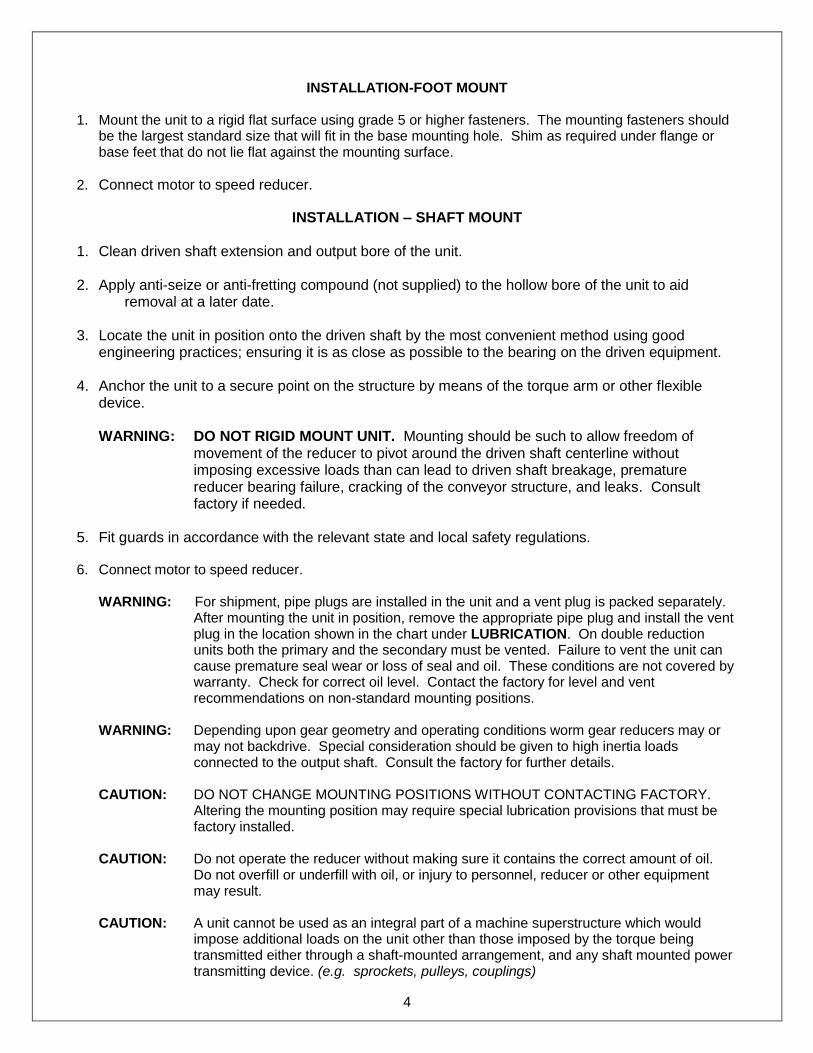
CAUTION: Units shipped with the bladder type pressure compensation system allow the unit to
be mounted in any position without changing the location of the bladder vent. However, for the unit to work properly, the pressure must be equalized before installation or leaking may occur. To equalize pressure, place the unit on a flat surface. Remove and then reinstall the drain plug opposite the bladder vent.
WARNING: With the exception of the bladder type vent system, the breather vent whether standard or pressure vent, will need to be installed by the customer in the proper location as noted by the diagram below. Failure to install the breather vent a will cause the unit to overheat and the oil seals to leak voiding the warranty.
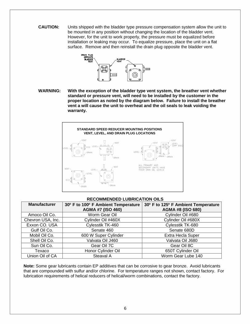
RECOMMENDED LUBRICATION OILS
Manufacturer 30 F to 100 F Ambient Temperature AGMA #7 (ISO 460)
30 F to 125 F Ambient Temperature AGMA #8 (ISO 680)
Amoco Oil Co. Worm Gear Oil Cylinder Oil #680
Chevron USA, Inc. Cylinder Oil #460X Cylinder Oil #680X
Exxon CO. USA Cylesstik TK-460 Cylesstik TK-680
Gulf Oil Co. Senate 460 Senate 680D
Mobil Oil Co. 600 W Super Cylinder Extra Hecla Super
Shell Oil Co. Valvata Oil J460 Valvata Oil J680
Sun Oil Co. Gear Oil 7C Gear Oil 8C
Texaco Honor Cylinder Oil 650T Cylinder Oil
Union Oil of CA Steaval A Worm Gear Lube 140
Note: Some gear lubricants contain EP additives that can be corrosive to gear bronze. Avoid lubricants that are compounded with sulfur and/or chlorine. For temperature ranges not shown, contact factory. For lubrication requirements of helical reducers of helical/worm combinations, contact the factory.
STANDARD SPEED REDUCER MOUNTING POSITIONS
VENT, LEVEL, AND DRAIN PLUG LOCATIONS
- 7 - 7
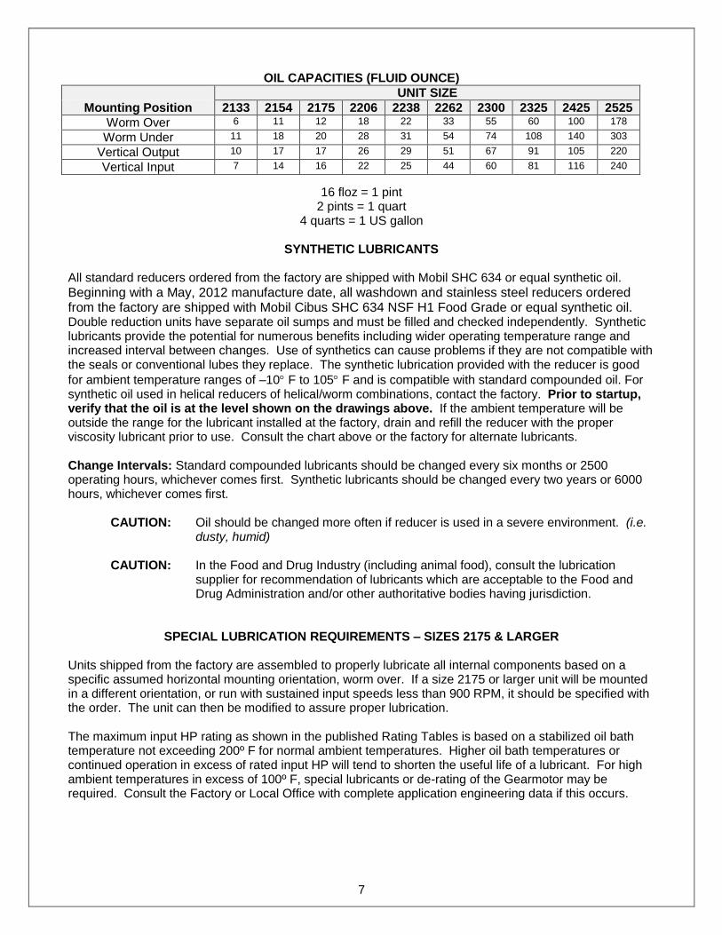
OIL CAPACITIES (FLUID OUNCE)
UNIT SIZE
Mounting Position 2133 2154 2175 2206 2238 2262 2300 2325 2425 2525
Worm Over 6 11 12 18 22 33 55 60 100 178
Worm Under 11 18 20 28 31 54 74 108 140 303
Vertical Output 10 17 17 26 29 51 67 91 105 220
Vertical Input 7 14 16 22 25 44 60 81 116 240
16 floz = 1 pint 2 pints = 1 quart
4 quarts = 1 US gallon
SYNTHETIC LUBRICANTS
All standard reducers ordered from the factory are shipped with Mobil SHC 634 or equal synthetic oil.
Beginning with a May, 2012 manufacture date, all washdown and stainless steel reducers ordered from the factory are shipped with Mobil Cibus SHC 634 NSF H1 Food Grade or equal synthetic oil. Double reduction units have separate oil sumps and must be filled and checked independently. Synthetic lubricants provide the potential for numerous benefits including wider operating temperature range and increased interval between changes. Use of synthetics can cause problems if they are not compatible with the seals or conventional lubes they replace. The synthetic lubrication provided with the reducer is good
for ambient temperature ranges of –10 F to 105 F and is compatible with standard compounded oil. For synthetic oil used in helical reducers of helical/worm combinations, contact the factory. Prior to startup, verify that the oil is at the level shown on the drawings above. If the ambient temperature will be outside the range for the lubricant installed at the factory, drain and refill the reducer with the proper viscosity lubricant prior to use. Consult the chart above or the factory for alternate lubricants. Change Intervals: Standard compounded lubricants should be changed every six months or 2500 operating hours, whichever comes first. Synthetic lubricants should be changed every two years or 6000 hours, whichever comes first.
CAUTION: Oil should be changed more often if reducer is used in a severe environment. (i.e. dusty, humid)
CAUTION: In the Food and Drug Industry (including animal food), consult the lubrication
supplier for recommendation of lubricants which are acceptable to the Food and Drug Administration and/or other authoritative bodies having jurisdiction.
SPECIAL LUBRICATION REQUIREMENTS – SIZES 2175 & LARGER Units shipped from the factory are assembled to properly lubricate all internal components based on a specific assumed horizontal mounting orientation, worm over. If a size 2175 or larger unit will be mounted in a different orientation, or run with sustained input speeds less than 900 RPM, it should be specified with the order. The unit can then be modified to assure proper lubrication. The maximum input HP rating as shown in the published Rating Tables is based on a stabilized oil bath temperature not exceeding 200º F for normal ambient temperatures. Higher oil bath temperatures or continued operation in excess of rated input HP will tend to shorten the useful life of a lubricant. For high ambient temperatures in excess of 100º F, special lubricants or de-rating of the Gearmotor may be required. Consult the Factory or Local Office with complete application engineering data if this occurs.

- 8 - 8
MAINTENANCE
Your Sterling Electric reducer has been tested and adjusted at the factory. Dismantling or replacement of components must be done by Sterling Electric to maintain the warranty. Frequently check the oil level of the reducer. If oil level is low, (refer to reducer vent and level position chart) add proper lubrication through the filler plug until it comes out the oil level plug. Inspect vent plug often to insure it is clean and operating.
CAUTION: Mounting bolts should be routinely checked to ensure that the unit is firmly anchored for proper operation.
Seals: The Sterling Electric line of speed reducers utilizes premium quality Viton seals which are the state-of-the-art in sealing technology. Seals are, however, a wear item and eventually need to be replaced. Seal kits are available and contain all the necessary seals, O-rings, and shims for a given reducer size based on style. Refer to the parts list for available kits. Replacement of the seals can be easily accomplished by following the steps below:
1. Remove the worn seal without damaging the shaft surface or the seal bore. This can be done by drilling a .062 diameter hole in the seal casing (being careful not to drill into the bearing behind the seal). Screw a #10 sheet metal screw into the hole and pry out the seal.
2. Clean the seal bore of sealant.
3. Before installing the new seal, use electrical tape to cover any keyways on the shaft to prevent
seal lip damage.
4. Grease the seal lips with bearing grease and apply a sealant to the seal bore.
5. Slide the seal into the shaft being careful not to fold the inner lip over on any shaft steps.
6. Press the seal into its bore with a sleeve that presses on the seal casing, being careful to keep the seal square in its bore.
CLASS OF SERVICE All capacity ratings are based on American Gear Manufacturers Association (AGMA) Standards. Load conditions must be within cataloged ratings published in the current Sterling Electric Catalog (available upon request).
LONG-TERM STORAGE (6 MONTHS UP) Units must be stored indoors, in a dry, warm temperature. Completely fill the unit with oil. Rotate the input shaft so that the output shaft rotates at least one revolution per month. Completely cover the input and output shaft with grease. At the time of start up, drain the storage oil, install the breather, and fill to the proper oil level with correct lubricant for the operating condition.

- 9 - 9
WARRANTY (LIMITED) The warranty will cover all of the parts in the gearmotor or reducer unit for 12 months from the date of shipment. The warranty is only for parts and labor. In no event shall our liability exceed the original price of the unit, nor does it cover cost of on site repair, installation, or freight. Contact the service department for a complete explanation as to the full warranty policies and conditions of sale. All dimensions designs and specifications are subject to change without notice.

- 10 - 10
2000RA SEAL AND BEARING SIZES
Input Quill or Solid Shaft Bearings Unit Bearing Part Number and Size
Size Series OD (mm) ID (mm) Width (mm) Sterling P/N
2133 6203 40 17 12 400-0004-6
2154 6304 52 20 15 400-0020-8
2175 6304 52 20 15 400-0020-8
2206 6305 62 25 17 400-0495-5
2238 6305 62 25 17 400-0495-5
2262 6306 72 30 19 400-0022-4
2300 6306 72 30 19 400-0022-4
2325 Solid 30306 72 30 20.75 400-0496-4
Quill 5306 72 30 30.2 400-0497-3
2425† Solid 30208 80 40 19.75 400-0502-8
Quill 30208 80 40 19.75 400-0502-8
2525‡ Solid 30309 100 45 27.25 400-0508-2
Quill 30309 100 45 27.25 400-0508-2 † For input speeds greater than 2400RPM or use with mechanical variable speed drives, 7208 angular contact bearings are used. ‡ For input speeds greater than 2400RPM or use with mechanical variable speed drives, 7309 angular contact bearings are used.
Solid Shaft Output Bearings Unit Bearing Part Number and Size
Size Series OD (mm) ID (mm) Width (mm) Sterling P/N
2133 30204 47 20 15.25 400-0498-2
2154 30204 47 20 15.25 400-0498-2
2175 30205 52 25 16.25 400-0499-1
2206 30206 62 30 17.25 400-0500-0
2238 30206 62 30 17.25 400-0500-0
2262 30207 72 35 18.25 400-0501-9
2300 30207 72 35 18.25 400-0501-9
2325 30208 80 40 19.75 400-0502-8
2425 32210 90 50 24.75 400-0509-1
2525 32211 100 55 26.75 400-0510-0
Hollow Shaft Output Bearings Unit Bearing Part Number and Size
Size Series OD (mm) ID (mm) Width (mm) Sterling P/N
2133 32005 47 25 15 400-0511-9
2154 32006 55 30 17 400-0512-8
2175 32008 68 40 19 400-0503-7
2206 32010 80 50 20 400-0505-5
2238 32011 90 55 23 400-0513-7
2262 32011 90 55 23 400-0513-7
2300 32014 110 70 25 400-0514-6
2325 32014 110 70 25 400-0514-6
2425 30214 125 70 26.25 400-0535-5
2525¢ 32022 170 110 38 400-0532-8
Solid Shaft Input Seals*
Unit Seal Part Number and Size
Size Shaft (mm) Bore (mm) Width (mm) Sterling P/N
2133 17 30 7 404-0285-5
2154 20 35 7 404-0286-4
2175 20 35 7 404-0286-4
2206 22 40 7 404-0287-3
2238 22 40 7 404-0287-3
2262 25 40 7 404-0288-2
2300 25 40 7 404-0288-2
2325 25 40 7 404-0288-2
2425 35 55 8 404-0294-6
2525§ 45 60 8 404-0295-5 *SEALS ARE AVAILABLE IN KITS ONLY. SEE PAGE 9
- 11 - 11
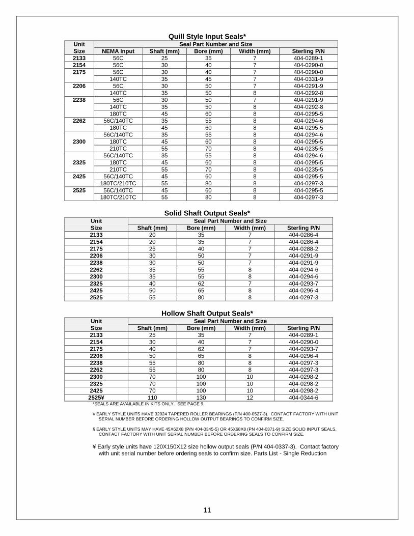
Quill Style Input Seals* Unit Seal Part Number and Size
Size NEMA Input Shaft (mm) Bore (mm) Width (mm) Sterling P/N
2133 56C 25 35 7 404-0289-1
2154 56C 30 40 7 404-0290-0
2175 56C 30 40 7 404-0290-0
140TC 35 45 7 404-0331-9
2206 56C 30 50 7 404-0291-9
140TC 35 50 8 404-0292-8
2238 56C 30 50 7 404-0291-9
140TC 35 50 8 404-0292-8
180TC 45 60 8 404-0295-5
2262 56C/140TC 35 55 8 404-0294-6
180TC 45 60 8 404-0295-5
56C/140TC 35 55 8 404-0294-6
2300 180TC 45 60 8 404-0295-5
210TC 55 70 8 404-0235-5
56C/140TC 35 55 8 404-0294-6
2325 180TC 45 60 8 404-0295-5
210TC 55 70 8 404-0235-5
2425 56C/140TC 45 60 8 404-0295-5
180TC/210TC 55 80 8 404-0297-3
2525 56C/140TC 45 60 8 404-0295-5
180TC/210TC 55 80 8 404-0297-3
Solid Shaft Output Seals*
Unit Seal Part Number and Size
Size Shaft (mm) Bore (mm) Width (mm) Sterling P/N
2133 20 35 7 404-0286-4
2154 20 35 7 404-0286-4
2175 25 40 7 404-0288-2
2206 30 50 7 404-0291-9
2238 30 50 7 404-0291-9
2262 35 55 8 404-0294-6
2300 35 55 8 404-0294-6
2325 40 62 7 404-0293-7
2425 50 65 8 404-0296-4
2525 55 80 8 404-0297-3
Hollow Shaft Output Seals*
Unit Seal Part Number and Size
Size Shaft (mm) Bore (mm) Width (mm) Sterling P/N
2133 25 35 7 404-0289-1
2154 30 40 7 404-0290-0
2175 40 62 7 404-0293-7
2206 50 65 8 404-0296-4
2238 55 80 8 404-0297-3
2262 55 80 8 404-0297-3
2300 70 100 10 404-0298-2
2325 70 100 10 404-0298-2
2425 70 100 10 404-0298-2
2525¥ 110 130 12 404-0344-6 *SEALS ARE AVAILABLE IN KITS ONLY. SEE PAGE 9.
¢ EARLY STYLE UNITS HAVE 32024 TAPERED ROLLER BEARINGS (P/N 400-0527-3). CONTACT FACTORY WITH UNIT SERIAL NUMBER BEFORE ORDERING HOLLOW OUTPUT BEARINGS TO CONFIRM SIZE.
§ EARLY STYLE UNITS MAY HAVE 45X62X8 (P/N 404-0345-5) OR 45X68X8 (PN 404-0371-9) SIZE SOLID INPUT SEALS.
CONTACT FACTORY WITH UNIT SERIAL NUMBER BEFORE ORDERING SEALS TO CONFIRM SIZE.
¥ Early style units have 120X150X12 size hollow output seals (P/N 404-0337-3). Contact factory
with unit serial number before ordering seals to confirm size. Parts List - Single Reduction
- 12 - 12
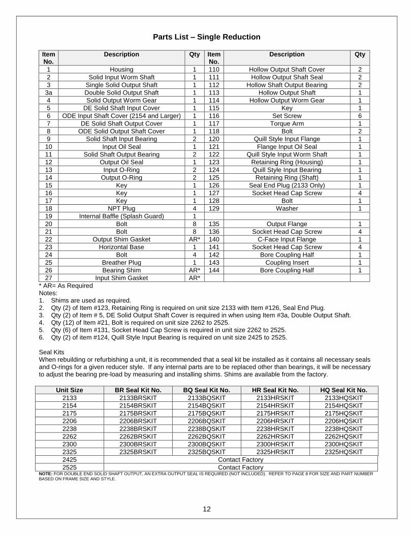
Parts List – Single Reduction
Item No.
Description Qty Item No.
Description
Qty
1 Housing 1 110 Hollow Output Shaft Cover 2
2 Solid Input Worm Shaft 1 111 Hollow Output Shaft Seal 2
3 Single Solid Output Shaft 1 112 Hollow Shaft Output Bearing 2
3a Double Solid Output Shaft 1 113 Hollow Output Shaft 1
4 Solid Output Worm Gear 1 114 Hollow Output Worm Gear 1
5 DE Solid Shaft Input Cover 1 115 Key 1
6 ODE Input Shaft Cover (2154 and Larger) 1 116 Set Screw 6
7 DE Solid Shaft Output Cover 1 117 Torque Arm 1
8 ODE Solid Output Shaft Cover 1 118 Bolt 2
9 Solid Shaft Input Bearing 2 120 Quill Style Input Flange 1
10 Input Oil Seal 1 121 Flange Input Oil Seal 1
11 Solid Shaft Output Bearing 2 122 Quill Style Input Worm Shaft 1
12 Output Oil Seal 1 123 Retaining Ring (Housing) 1
13 Input O-Ring 2 124 Quill Style Input Bearing 1
14 Output O-Ring 2 125 Retaining Ring (Shaft) 1
15 Key 1 126 Seal End Plug (2133 Only) 1
16 Key 1 127 Socket Head Cap Screw 4
17 Key 1 128 Bolt 1
18 NPT Plug 4 129 Washer 1
19 Internal Baffle (Splash Guard) 1
20 Bolt 8 135 Output Flange 1
21 Bolt 8 136 Socket Head Cap Screw 4
22 Output Shim Gasket AR* 140 C-Face Input Flange 1
23 Horizontal Base 1 141 Socket Head Cap Screw 4
24 Bolt 4 142 Bore Coupling Half 1
25 Breather Plug 1 143 Coupling Insert 1
26 Bearing Shim AR* 144 Bore Coupling Half 1
27 Input Shim Gasket AR*
* AR= As Required Notes: 1. Shims are used as required. 2. Qty (2) of Item #123, Retaining Ring is required on unit size 2133 with Item #126, Seal End Plug. 3. Qty (2) of Item # 5, DE Solid Output Shaft Cover is required in when using Item #3a, Double Output Shaft. 4. Qty (12) of Item #21, Bolt is required on unit size 2262 to 2525. 5. Qty (6) of Item #131, Socket Head Cap Screw is required in unit size 2262 to 2525. 6. Qty (2) of item #124, Quill Style Input Bearing is required on unit size 2425 to 2525. Seal Kits When rebuilding or refurbishing a unit, it is recommended that a seal kit be installed as it contains all necessary seals and O-rings for a given reducer style. If any internal parts are to be replaced other than bearings, it will be necessary to adjust the bearing pre-load by measuring and installing shims. Shims are available from the factory.
Unit Size BR Seal Kit No. BQ Seal Kit No. HR Seal Kit No. HQ Seal Kit No.
2133 2133BRSKIT 2133BQSKIT 2133HRSKIT 2133HQSKIT
2154 2154BRSKIT 2154BQSKIT 2154HRSKIT 2154HQSKIT
2175 2175BRSKIT 2175BQSKIT 2175HRSKIT 2175HQSKIT
2206 2206BRSKIT 2206BQSKIT 2206HRSKIT 2206HQSKIT
2238 2238BRSKIT 2238BQSKIT 2238HRSKIT 2238HQSKIT
2262 2262BRSKIT 2262BQSKIT 2262HRSKIT 2262HQSKIT
2300 2300BRSKIT 2300BQSKIT 2300HRSKIT 2300HQSKIT
2325 2325BRSKIT 2325BQSKIT 2325HRSKIT 2325HQSKIT
2425 Contact Factory
2525 Contact Factory NOTE: FOR DOUBLE END SOLID SHAFT OUTPUT, AN EXTRA OUTPUT SEAL IS REQUIRED (NOT INCLUDED). REFER TO PAGE 8 FOR SIZE AND PART NUMBER BASED ON FRAME SIZE AND STYLE.

- 13 - 13
Parts List – Double Reduction (Worm / Worm)
Item No.
Description Qty Item No.
Description
Qty
1 Housing (Primary or Secondary) 1 122 Quill Style Input Worm Shaft 1
4 Solid Output Worm Gear 1 123 Retaining Ring (Housing) 1
6 ODE Input Shaft Cover 1 124 Quill Style Input Bearing 1
8 ODE Solid Output Shaft Cover 1 125 Retaining Ring (Shaft) 1
11 Solid Shaft Output Bearing 2
12 Output Oil Seal 1 200 Double Reduction Adapter 1
13 Input O-Ring 1 201 Dbl Reduction Primary Unit Output Shaft 1
14 Output O-Ring 2 202 Key 1
15 Key 1 203 Bolt 4
19 Internal Baffle (Splash Guard) 1
20 Bolt 4
21 Bolt 4
22 Output Shim Gasket AR*
26 Bearing Shim AR*
* AR= As Required Notes: 1. Shims are used as required. 2. The primary gearbox in the ratio combination is considered the input or motor end reducer. 3. The secondary gearbox in the ratio combination is considered the output or load end reducer. Seal Kits When Ordering seal kits for double reduction units, refer to the information for the single reduction units on the previous page. Double reduction units will take two seal kits, one for the primary and one for the secondary. The primary unit will take either the BR or BQ seal kit depending on the input configuration. The secondary unit will take either a BQ or HQ seal kit depending on the output configuration. All outputs for the primary units are solid shaft. All inputs for the secondary units are quill style.
Worm / Worm Ratio Combinations
2154DW 2175DW 2206DW 2238DW 2262DW 2300DW 2325DW 2425DW 2525DW
Total P S P S P S P S P S P S P S P S P S
Ratio 2133 2154 2133 2175 2133 2206 2133 2238 2133 2262 2154 2300 2154 2325 2206 2425 2262 2525
75:1 5 15 5 15 5 15 5 15 5 15 5 15 5 15 5 15 5 15
100:1 5 20 5 20 5 20 5 20 5 20 5 20 5 20 5 20 5 20
150:1 10 15 10 15 10 15 10 15 10 15 10 15 10 15 10 15 10 15
200:1 10 20 10 20 10 20 10 20 10 20 10 20 10 20 10 20 10 20
250:1 10 25 10 25 10 25 10 25 10 25 10 25 10 25 10 25 10 25
300:1 10 30 10 30 10 30 10 30 10 30 10 30 10 30 10 30 10 30
400:1 20 20 20 20 20 20 20 20 20 20 20 20 20 20 20 20 20 20
500:1 25 20 25 20 25 20 25 20 25 20 25 20 25 20 25 20 25 20
600:1 20 30 20 30 20 30 20 30 20 30 20 30 20 30 20 30 20 30
750:1 25 30 25 30 25 30 25 30 25 30 25 30 25 30 25 30 25 30
900:1 30 30 30 30 30 30 30 30 30 30 30 30 30 30 30 30 30 30
1000:1 50 20 50 20 50 20 50 20 50 20 50 20 50 20 50 20 50 20
1200:1 40 30 40 30 40 30 40 30 40 30 40 30 40 30 40 30 40 30
1500:1 50 30 50 30 50 30 50 30 50 30 50 30 50 30 50 30 50 30
1800:1 60 30 60 30 60 30 60 30 60 30 60 30 60 30 60 30 60 30
2400:1 60 40 60 40 60 40 60 40 60 40 60 40 60 40 60 40 60 40
3000:1 60 50 60 50 60 50 60 50 60 50 60 50 60 50 60 50 60 50
3600:1 60 60 60 60 60 60 60 60 60 60 60 60 60 60 60 60 60 60
P = Primary (Input) unit. S = Secondary (output) unit Note: Actual ratio combination supplied by factory may vary from above depending on application and manufacturing requirements. When ordering replacement parts, provide complete serial number and part number.
- 14 - 14
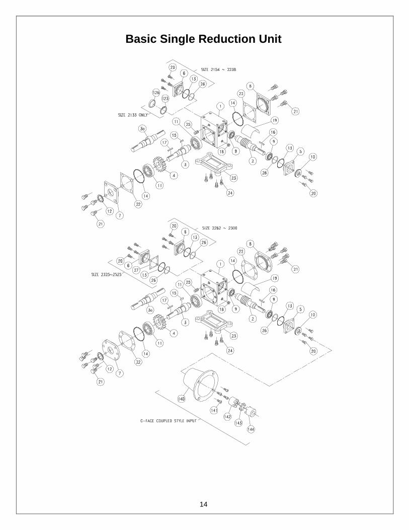
Basic Single Reduction Unit

- 15 - 15
Hollow Output Shaft Unit

- 16 - 16
Quill Style Input

- 17 - 17
Double Reduction Style (Worm/ Worm)

- 18 - 18
Double Reduction with Helical Primary (Ratio Multiplier)
Helical / Worm Ratio Combinations
2175HW 2206HW 2238HW 2262HW 2300HW 2325HW 2425HW 2525HW
Total P S P S P S P S P S P S P S P S
Ratio 2 2175 2 2206 2 2238 2 2262 2 2300 2 2325 3 2425 3 2525
10:1 2 5 2 5 2 5 2 5 2 5 2 5 2 5 2 5
20:1 2 10 2 10 2 10 2 10 2 10 2 10 2 10 2 10
25:1 5 5 5 5 5 5 5 5 5 5 5 5 5 5 5 5
30:1 2 15 3 10 3 10 3 10 3 10 3 10 3 10 2 15
40:1 4 10 4 10 4 10 4 10 4 10 4 10 4 10 2 20
45:1 3 15 3 15 3 15 3 15 3 15 3 15 3 15 3 15
50:1 5 10 5 10 5 10 5 10 5 10 5 10 5 10 2 25
60:1 4 15 4 15 4 15 3 20 4 15 4 15 4 15 4 15
75:1 5 15 5 15 5 15 5 15 5 15 5 15 5 15 5 15
80:1 4 20 4 20 4 20 4 20 4 20 4 20 4 20 4 20
100:1 4 25 4 25 4 25 4 25 4 25 4 25 4 25 4 25
125:1 5 25 5 25 5 25 5 25 5 25 5 25 5 25 5 25
150:1 5 30 5 30 5 30 5 30 5 30 5 30 5 30 5 30
200:1 5 40 5 40 5 40 5 40 5 40 5 40 5 40 5 40
250:1 5 50 5 50 5 50 5 50 5 50 5 50 5 50 5 50
300:1 5 60 5 60 5 60 5 60 5 60 5 60 5 60 5 60
P = Primary (Input) unit. S = Secondary (output) unit Note: Actual ratio combination supplied by factory may vary from above depending on application and manufacturing requirements. When ordering replacement parts, provide complete serial number and part number.
LUBRICATION (HELICAL PRIMARY ONLY)
All standard helical ratio multipliers ordered from the factory are shipped with standard compounded lubricant and is
good for ambient temperature ranges of 30 F to 104 F. Double reduction units have separate oil sumps and must be filled and checked independently. Use of synthetics can cause problems if they are not compatible with the seals or conventional lubes they replace. Prior to startup, verify that the oil is at the level shown on the drawing below. If the ambient temperature will be outside the range for the lubricant installed at the factory, drain and refill the reducer with the proper viscosity lubricant prior to use.
VENT PLUG LOCATION
Before putting the unit into operation, substitute the vent plug for the solid plug at the position desired. Arrows indicate the recommended vent plug locations.
CAUTION: On ALL quill style input units, cast iron and stainless with the input mounted vertical shaft up or input under will require a double input seal arrangement to prevent leakage or C-face coupled style units should be used. Consult factory
]
OIL & WEIGHT SPECIFICATIONS Oil Type AGMA SAE ISO Oil Capacity Size 1 Size 2 Size 3
(Viscosity) #4 40 Wt. 150 6 fl oz 14 fl oz 14 fl oz
- 19 - 19
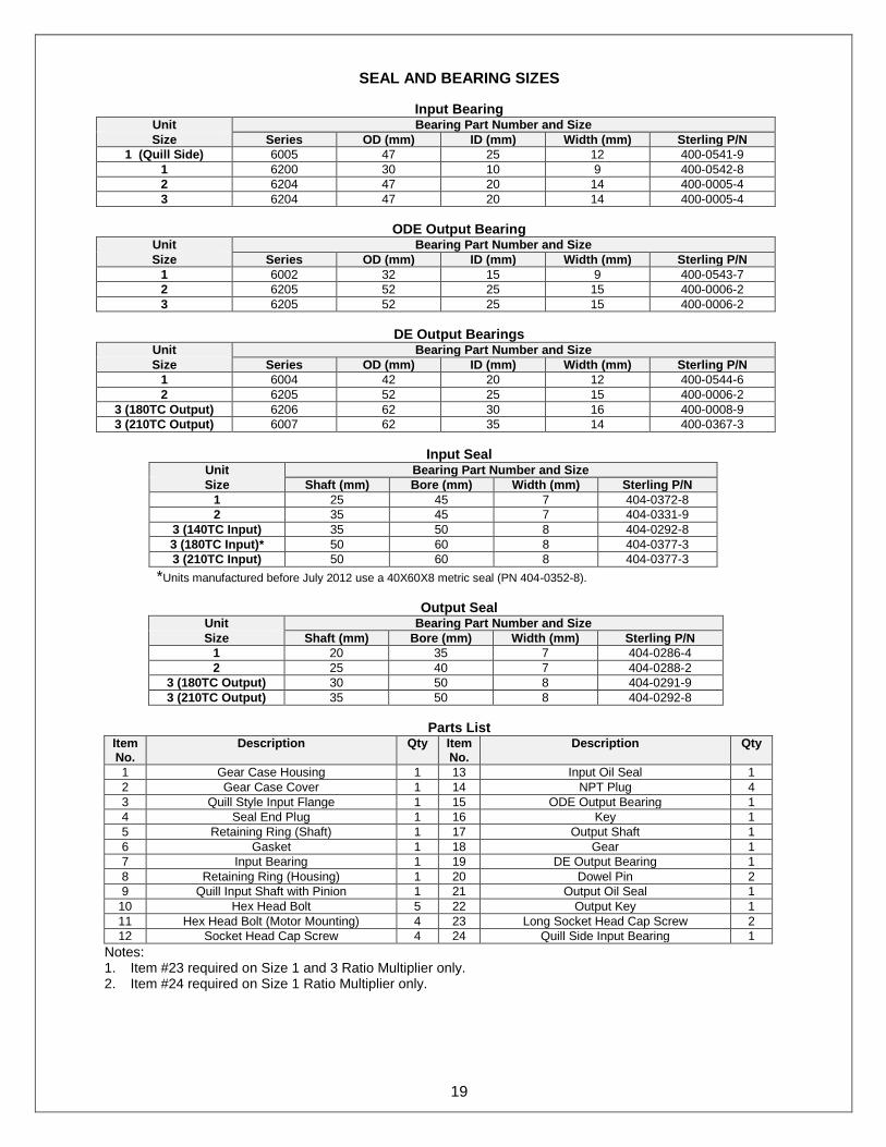
SEAL AND BEARING SIZES
Input Bearing Unit Bearing Part Number and Size
Size Series OD (mm) ID (mm) Width (mm) Sterling P/N
1 (Quill Side) 6005 47 25 12 400-0541-9
1 6200 30 10 9 400-0542-8
2 6204 47 20 14 400-0005-4
3 6204 47 20 14 400-0005-4
ODE Output Bearing Unit Bearing Part Number and Size
Size Series OD (mm) ID (mm) Width (mm) Sterling P/N
1 6002 32 15 9 400-0543-7
2 6205 52 25 15 400-0006-2
3 6205 52 25 15 400-0006-2
DE Output Bearings Unit Bearing Part Number and Size
Size Series OD (mm) ID (mm) Width (mm) Sterling P/N
1 6004 42 20 12 400-0544-6
2 6205 52 25 15 400-0006-2
3 (180TC Output) 6206 62 30 16 400-0008-9
3 (210TC Output) 6007 62 35 14 400-0367-3
Input Seal Unit Bearing Part Number and Size
Size Shaft (mm) Bore (mm) Width (mm) Sterling P/N
1 25 45 7 404-0372-8
2 35 45 7 404-0331-9
3 (140TC Input) 35 50 8 404-0292-8
3 (180TC Input)* 50 60 8 404-0377-3
3 (210TC Input) 50 60 8 404-0377-3
*Units manufactured before July 2012 use a 40X60X8 metric seal (PN 404-0352-8).
Output Seal Unit Bearing Part Number and Size
Size Shaft (mm) Bore (mm) Width (mm) Sterling P/N
1 20 35 7 404-0286-4
2 25 40 7 404-0288-2
3 (180TC Output) 30 50 8 404-0291-9
3 (210TC Output) 35 50 8 404-0292-8
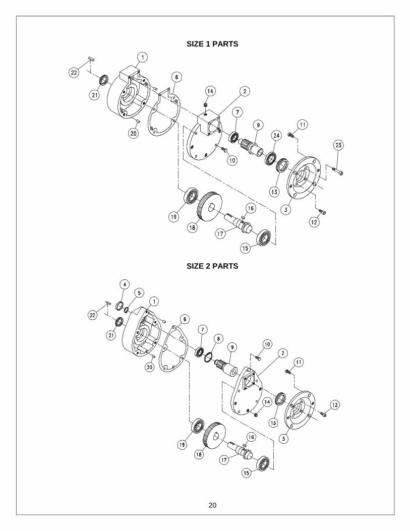
Parts List Item No.
Description Qty Item No.
Description
Qty
1 Gear Case Housing 1 13 Input Oil Seal 1
2 Gear Case Cover 1 14 NPT Plug 4
3 Quill Style Input Flange 1 15 ODE Output Bearing 1
4 Seal End Plug 1 16 Key 1
5 Retaining Ring (Shaft) 1 17 Output Shaft 1
6 Gasket 1 18 Gear 1
7 Input Bearing 1 19 DE Output Bearing 1
8 Retaining Ring (Housing) 1 20 Dowel Pin 2
9 Quill Input Shaft with Pinion 1 21 Output Oil Seal 1
10 Hex Head Bolt 5 22 Output Key 1
11 Hex Head Bolt (Motor Mounting) 4 23 Long Socket Head Cap Screw 2
12 Socket Head Cap Screw 4 24 Quill Side Input Bearing 1
Notes: 1. Item #23 required on Size 1 and 3 Ratio Multiplier only. 2. Item #24 required on Size 1 Ratio Multiplier only.
- 20 - 20
SIZE 1 PARTS
SIZE 2 PARTS

- 21 - 21
SIZE 3 PARTS