Söll GlideLoc Universal II Fall Arrester user manual
19
Safety At Height Limited Unit 1 Pennine View, Marple, Stockport Cheshire, SK67JW Tel: +44(0)161 446 5615 www.safety-height.co.uk 1 Usage and maintenance manual for the fall arrester system of the Söll GlideLoc ® type with a guided type fall arrester “Söll Universal II” Order no. 25604/25805/27192 in accordance with EN 353-1:2002 / CNB/P/11.073 Serial number: Date of purchase: (The initial test is done by the manufacturer before shipment. The yearly inspections have to be documented in the inspection logbook.) The user must fill in the following details using an indelible pen: Date of commissioning: Operating company/user: Street: Location: Tel.: Fax:
Transcript of Söll GlideLoc Universal II Fall Arrester user manual

Safety At Height LimitedUnit 1 Pennine View, Marple, Stockport
Cheshire, SK67JWTel: +44(0)161 446 5615 www.safety-height.co.uk
1
Usage and maintenance manualfor the fall arrester system of
the Söll GlideLoc® type with a guided type fall arrester
“Söll Universal II”Order no. 25604/25805/27192
in accordance with EN 353-1:2002 / CNB/P/11.073
Serial number:
Date of purchase:(The initial test is done by the manufacturer before shipment.
The yearly inspections have to be documented in the inspection logbook.)
The user must fill in the following details using an indelible pen:
Date of commissioning:
Operating company/user:
Street:
Location:
Tel.: Fax:
Safety At Height LimitedUnit 1 Pennine View, Marple, Stockport
Cheshire, SK67JWTel: +44(0)161 446 5615 www.safety-height.co.uk
2
ContentsPage
A General information 3
B Inspection before climbing 4
C Using the fall arrester 5
D Removing the fall arrester 12
E Maintenance 13
F Care 18
G Storage 18
H Inspection logbook 19
This manual is protected by copyright.
Duplicating and circulating this manual is not permitted withoutwritten consent of the author as per §§16, 17 German CopyrightAct (UrhG), and Honeywell Fall Protection Deutschland GmbH& Co. KG reserves the right to prosecute as per § 106 German
Copyright Act (UrhG) in case of any violation.

Safety At Height LimitedUnit 1 Pennine View, Marple, Stockport
Cheshire, SK67JWTel: +44(0)161 446 5615 www.safety-height.co.uk
3
A General informationA 1. Read this manual and understand its contents before usage. Actions contrave-
ning this manual may put people’s lives at risk.
A 2. For the users’ safety, it is important that the retailer provides this manual inrespective country’s language if this system is re-sold in another country.
A 3. The maximum user load (including the clothing and equipment) may not exceed140 kg.Operating temperature for the fall protection system: -40 °C to +70 °C
A 4. A safety distance of 3.0 m between the users must not be undershot.
A 5. The “regulations for using personal protective equipment against falls from aheight”, i.e. BGR 198, of the Institute for statutory accident insurance and pre-vention as well as the rules for using personal protective equipment for holdingand rescuing, i.e. BGR 199, must be observed.
A 6. The “Söll-Universal II” fall arrester is component of the Söll fall protection sy-stem with a fixed guide of the Söll GlideLoc® type compliant with EN 353/Part1 and has been designed for use as personal protective equipment only for theintended use of the Söll fall protection system. The operating company of thefall arrester system must suitably ensure that the full body harness and the fallarrester belong to the user and that they are used according to the instructions.After use, the fall arrester must not be left inside the fall protection system.
The “Söll Universal II” fall arrester must be operated only in the originalSöll fall arrester systems that have the Söll GlideLoc® type EU prototypetest certificate. Using systems of other manufacturers may hamper the func-tioning of the fall arrester.
In such cases Honeywell Fall Protection Deutschland GmbH & Co. KG and itsauthorised dealers refuse product liability. The operating company shall thenbe completely responsible.

Safety At Height LimitedUnit 1 Pennine View, Marple, Stockport
Cheshire, SK67JWTel: +44(0)161 446 5615 www.safety-height.co.uk
4
A 7. Full body harnesses must be approved in accordance with EN 361. Onlycertified arrester elements (marking with “A”) may be used.
A 8. The fall arrester system must be handled with care.
A 9. Relevant notified body: DEKRA EXAM GmbH, Dinnendahlstr. 9,44809 Bochum, CE 0158.
B Inspection before climbingCaution - risk to life:The “Söll Universal II” fall arrester can be used in all Söll GlideLoc systemswith anchorage rails except of steel and stainless steel guide railswithout catch noses (until year 1984).
B 1. Before using the guide, fall arrester, intermediate joint and karabiner hooks,always check their usage capability and correct functioning (see the Mainte-nance check list for this). Especially ensure that the locking axle (1.5) isretracted up to the end stop in the housing using the spring pre-tensi-on.
B 2. Do not use the fall arrester system if there are apparent defects or doubtsregarding the safety of the system. Do not use it until an expert approvesit for further use. Send the system components back to the manufacturer ifrequired.
B 3. Before and while climbing, ensure safe and effective implementation of res-cue measures.
B 4. The user must be in good health and must not be under the influence of alco-hol, drugs or medicines.
B 5. Note:Utmost care must be taken when ascending and descending in the first 2m of the ascent route since it may not be possible to prevent the user fromhitting the ground in some cases.
B 6. Warning:The specific influence of the arresting mechanism when ascending and de-scending may hamper the safe functioning of the fall arrester.

Safety At Height LimitedUnit 1 Pennine View, Marple, Stockport
Cheshire, SK67JWTel: +44(0)161 446 5615 www.safety-height.co.uk
5
C Using the fall arresterFigure 1Warning
C 1. The fall arrester system and the full body harness secure the users againstfalling when ascending or descending. When working in or next to the ascentroute and when executing tasks and actions that are not a part of the usualascent and descent movements, the climber must additionally secure himself/herself with a lanyard in accordance with EN 354 or a lanyard for the workingpositioning belts in accordance with EN 358. (Safety using an anchor device)This is also applicable for idle positions that are intended to take a breakon the fall arrest ladder. Only suitable anchor devices such as a mountingbracket must be used for this. In all these situations, the lanyard must be heldtight in order to prevent a fall (see figure 1).
Figure 1
An EN 353-1 compliant fall arrester system should be used only by those per-sons who• are trained and/or are experts or• are directly supervised by a trained and/or an expert person.
EN 354/355 EN 358

Safety At Height LimitedUnit 1 Pennine View, Marple, Stockport
Cheshire, SK67JWTel: +44(0)161 446 5615 www.safety-height.co.uk
6
Figure 2C 2. Use at the beginning of the ascent route:Push the fall arrester into the lo-
wer end of the anchorage rail (6.0) or in the recess (6.1) (that must alwaysbe provided at the stomach height or deeper) (see view “A”). The laterallyprotruding locking pin (1.2) must be on the right side and the engraved arrow(1.10) on the side of the fall arrester must point upwards.
The locking pin (1.2) and the end stop (7.0) prevent the incorrect use ofthe fall arrester and unintended slipping from the anchorage rail.
Figure 2
Running rollers of the locking axle (1.5) must be in the anchorage railat the time of using. If required, press the locking axle from top through thehousing in the direction of the anchorage rail.
Warning:Crossing the end stop is allowed only• in the areas without the risk of a fall from heights or• if the safety against falls from heights is ensured using other means.
View “A”
Safety At Height LimitedUnit 1 Pennine View, Marple, Stockport
Cheshire, SK67JWTel: +44(0)161 446 5615 www.safety-height.co.uk
7
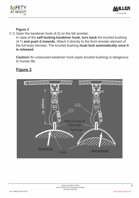
Figure 3C 3. Open the karabiner hook (4.0) on the fall arrester.
In case of the self-locking karabiner hook, turn back the knurled bushing(4.1) and push it inwards. Attach it directly to the front arrester element ofthe full body harness. The knurled bushing must lock automatically once itis released.
Caution! An unsecured karabiner hook (open knurled bushing) is dangerousto human life.
Figure 3
Correctbody Incorrect
front D-ring ofharnessharness
Safety At Height LimitedUnit 1 Pennine View, Marple, Stockport
Cheshire, SK67JWTel: +44(0)161 446 5615 www.safety-height.co.uk
8
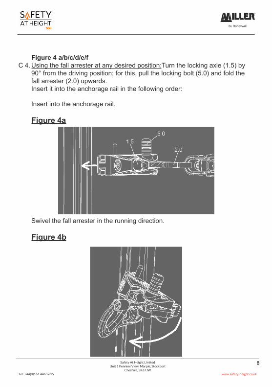
Figure 4 a/b/c/d/e/fC 4. Using the fall arrester at any desired position:Turn the locking axle (1.5) by
90° from the driving position; for this, pull the locking bolt (5.0) and fold thefall arrester (2.0) upwards.Insert it into the anchorage rail in the following order:
Insert into the anchorage rail.
Figure 4a
Swivel the fall arrester in the running direction.
Figure 4b
Safety At Height LimitedUnit 1 Pennine View, Marple, Stockport
Cheshire, SK67JWTel: +44(0)161 446 5615 www.safety-height.co.uk
9
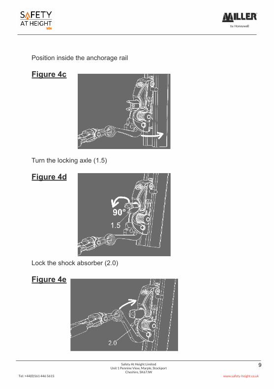
Position inside the anchorage rail
Figure 4c
Turn the locking axle (1.5)
Figure 4d
Lock the shock absorber (2.0)
Figure 4e

Safety At Height LimitedUnit 1 Pennine View, Marple, Stockport
Cheshire, SK67JWTel: +44(0)161 446 5615 www.safety-height.co.uk
10
After locking the shock absorber, check its functioning quickly.
Figure 4f
Running rollers of the locking axle (1.5) must be in the anchorage railat the time of using. The shock absorber must lock in distinctly. In thelocked position, the shock absorber must prevent the locking axle fromtwisting.Remove the fall arrester in the reverse order. For this, first pull the lockingbolt (5.0).
Attention!When using the“UNIVERSAL II”
fall arrester with the change-over rail,ensure that the
running direction is correct (arrow up).

Safety At Height LimitedUnit 1 Pennine View, Marple, Stockport
Cheshire, SK67JWTel: +44(0)161 446 5615 www.safety-height.co.uk
11
attachementelement
attachementelement
front arrester element
Figure 5 Warning: Risk to life!The karabiner hook of the fall arrester must be directly inserted into thefront arrester element (marking with “A”) of the full body harness for thevertical and horizontal usage in compliance with EN 353/1. The lengthbetween the outer edge of the anchorage rail and the internally bent eyeleton the harness may not exceed 225 mm (see Figure 3).
Figure 5
C 5. The stomach or chest harness of the full body harness must fit firmlyon the body. (See figure 3)

Safety At Height LimitedUnit 1 Pennine View, Marple, Stockport
Cheshire, SK67JWTel: +44(0)161 446 5615 www.safety-height.co.uk
12
C 6. The ladder can now be used. When descending, the latch (Figure 7 / detail1.11) of the fall arrester must be unlocked.Two options are available for this:a) The user can lean backwards and unlock the latchb) If the user goes near the ladder, the fall arrester suspends downwards.
The latch is unlocked due to the weight of the fall arrester and it remainsunlocked as long as climber moves up or down uniformly without jerks.
Attention! Before and while using this fall arrester, ensure that the lockingaxle (1.5) is automatically pulled up to the end stop in the housing using thespring pre-tension.
D Removing the fall arrester from theanchorage rail
Warning:Protection against falls from heights must be ensured using a different me-thod before removing the fall arrester from the anchorage rail.
D 1. To remove the fall arrester from the anchorage rail, the corresponding endstop (Figure 2 / detail 7.0) must be crossed. For this, fold the locking latch(Figure 2 / detail 7.1) of the end stop upwards/downwards. When using anexiting device, observe its valid operating manual.
D 2. To remove the fall arrester from the desired position on the ascent route,proceed in the reverse order that has been described for inserting in chapterC 4. For this, pull the locking bolt on the right side of the fall arrester.

Safety At Height LimitedUnit 1 Pennine View, Marple, Stockport
Cheshire, SK67JWTel: +44(0)161 446 5615 www.safety-height.co.uk
13
E Maintenance
E 1. A fall arrester system damaged due to a fall must be used again only aftertesting by an expert. The fall arrester and the manual must be sent to themanufacturer’s workshop for checking and maintenance.
E 2. Depending on the application and operating conditions, an expert must checkthe fall arrester for its flawless condition as required, however at least once ayear.
An expert for the personal protective equipment is:
A person who can has a certificate for successfully participating in a coursecompliant with the "fundamental principles for selecting and training the ex-perts in the field of personal protective equipment against falls from a heightand certifying their qualification", i.e. BGG 906.
E 3. Expert test (also see Figure 7 for this)
Use the “maintenance check list” for the expert test.
An expert can rectify the following defects:• Removing dirt (concrete, mortar, colour, etc.) on the body and running sur-
faces• Cleaning the labels• Replacing the stickers
In case of dirt inside the shuttle and defects that necessitate partial dismant-ling of components, the shuttle must be sent to the manufacturer’s workshopwith suitable notification (and with the manual) to rectify the defects. Thisprocess must be recorded in the annexe of the check list (space for com-ments).
Owing to safety reasons, repairs may be carried out only themanufacturer’s workshop.
Safety At Height LimitedUnit 1 Pennine View, Marple, Stockport
Cheshire, SK67JWTel: +44(0)161 446 5615 www.safety-height.co.uk
14
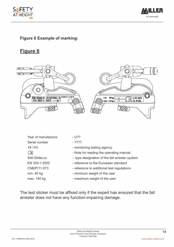
Figure 6 Example of marking:
Figure 6
The test sticker must be affixed only if the expert has ensured that the fallarrester does not have any function-impairing damage.
Year of manufacture - U??Serial number - ????
- monitoring testing agency- Note for reading the operating manual
Söll GlideLoc - type designation of the fall arrester systemEN 353-1:2002 - reference to the European standardCNB/P/11.073 - reference to additional test regulationsmin. 40 kg - minimum weight of the usermax. 140 kg - maximum weight of the user
Safety At Height LimitedUnit 1 Pennine View, Marple, Stockport
Cheshire, SK67JWTel: +44(0)161 446 5615 www.safety-height.co.uk
15
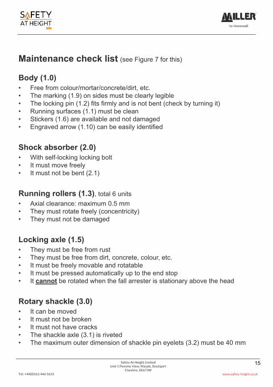
Maintenance check list (see Figure 7 for this)
Body (1.0)• Free from colour/mortar/concrete/dirt, etc.• The marking (1.9) on sides must be clearly legible• The locking pin (1.2) fits firmly and is not bent (check by turning it)• Running surfaces (1.1) must be clean• Stickers (1.6) are available and not damaged• Engraved arrow (1.10) can be easily identified
Shock absorber (2.0)• With self-locking locking bolt• It must move freely• It must not be bent (2.1)
Running rollers (1.3), total 6 units• Axial clearance: maximum 0.5 mm• They must rotate freely (concentricity)• They must not be damaged
Locking axle (1.5)• They must be free from rust• They must be free from dirt, concrete, colour, etc.• It must be freely movable and rotatable• It must be pressed automatically up to the end stop• It cannot be rotated when the fall arrester is stationary above the head
Rotary shackle (3.0)• It can be moved• It must not be broken• It must not have cracks• The shackle axle (3.1) is riveted• The maximum outer dimension of shackle pin eyelets (3.2) must be 40 mm

Safety At Height LimitedUnit 1 Pennine View, Marple, Stockport
Cheshire, SK67JWTel: +44(0)161 446 5615 www.safety-height.co.uk
16
Karabiner hook (4.0)• It must not be bent• It must not have cracks• It must not be broken• The knurled bushing (4.1) must not be damaged• It must be possible to open the knurled bushing (4.1) easily• The knurled bushing must close and lock automatically after opening and re-
leasing• The locking pin (4.2) is available
Locking bolt (5.0)• They must be free from rust• They must be free from dirt, concrete, colour, etc.• It must not be damaged• It must move freely• It must lock automatically
Space for comments:_________________________________________________________________
_________________________________________________________________
_________________________________________________________________
_________________________________________________________________
_________________________________________________________________
_________________________________________________________________
_________________________________________________________________

Safety At Height LimitedUnit 1 Pennine View, Marple, Stockport
Cheshire, SK67JWTel: +44(0)161 446 5615 www.safety-height.co.uk
17
Figure 7<
83m
m
1.3
2.11.9
< 40
mm
1.2
1.0
1.6
4.0
4.1
5.0
4.2
3.2
3.1
2.0
1.1
1.101.5
3.0
1.11

Safety At Height LimitedUnit 1 Pennine View, Marple, Stockport
Cheshire, SK67JWTel: +44(0)161 446 5615 www.safety-height.co.uk
18
F Care
F 1. Wash the entire fall arrester with water and dry it using a suction cloth. Donot use heat sources for drying.DO NOT wash it with a quick cleaner, thinner or degreaser containing trichlo-roethane. Do not use grease.
F 2. Running rollers (Figure 7 / detail 1.3) have plain bearings and have beenlubricated in the factory.
F 3. Lubricate the rotary shackle (Figure 7 / detail 3.0) slightly.
F 4. Lubricate the knurled bushing (Figure 7 / detail 4.1) if required.
F 5. Attention! Do not bring the fall arrester in contact with chemicals.
G Storage
The fall arrester should be kept clean and as dry and dust-free as possible,and should not be stored near heat sources.
When transporting ensure that the fall arrester is protected from damage.

Safety At Height LimitedUnit 1 Pennine View, Marple, Stockport
Cheshire, SK67JWTel: +44(0)161 446 5615 www.safety-height.co.uk
19
H Inspection logbook
DateReason for working on thesystem (regular inspection
or repair)
Damage determined, repairs carriedout and other important details
Name/signature ofthe expert
Date of thenext regularinspection