SLK s o l a r s y s t e m s - Sollatek · s o l a r s y s t e m s ™ SLK SOLAR LIGHTING KIT...
12
solar systems ™ SLK SOLAR LIGHTING KIT Installation Manual for Solar Lighting Kit Solar Module Solar Module SPCC10 Charge Controller Lumina Fuse Fuse Lumina + - + - + - + - + - + - + - + - + - Battery
Transcript of SLK s o l a r s y s t e m s - Sollatek · s o l a r s y s t e m s ™ SLK SOLAR LIGHTING KIT...

s o l a r s y s t e m s
™
SLKSOLAR LIGHTING KIT
Installation Manual for Solar Lighting Kit
Solar Module
Solar Module
SPCC10Charge Controller
Lumina
Fuse
Fuse
Lumina
+ - + - + - + - + - + - + - + -
+ -Battery
Installation Manual for Solar Lighting Kit
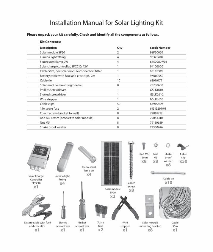
Please unpack your kit carefully. Check and identify all the components as follows.
Kit Contents:
Description Qty Stock NumberSolar module SP20 2 9SPS0020Lumina light fitting 4 96321200Fluorescent lamp 9W 4 68509807/01Solar charge controller, SPCC10, 12V 1 94100000Cable 50m, c/w solar module connectors fitted 1 63132609Battery cable with fuse and croc clips, 2m 1 9K000050Cable tie 10 63910177Solar module mounting bracket 8 73230608Phillips screwdriver 1 GSLK1610Slotted screwdriver 1 GSLK2610Wire stripper 1 GSLK0610Cable clips 50 6391560915A spare fuse 2 61315291/01Coach screw (bracket to wall) 8 79081712Bolt M5 12mm (bracket to solar module) 8 79054310Nut M5 8 79150659Shake proof washer 8 79350676
Solar Charge Controller
SPCC10
x1
Lumina light fitting
x4
Fluorescent lamp 9W
x4
Solar module SP20
x2
Bolt M5 12mm
x8
Coach screw
x8
Nut M5
x8
Shake proof
washer
x8
Battery cable with fuse and croc clips
x1
Slotted screwdriver
x1
Phillipsscrewdriver
x1
Wire stripper
x1
Cable 50m
x1
Cable clip
x50
Cable tie
x10
Spare fuse
x2
Solar module mounting bracket
x8

SAFETY WARNING:
• Take great care when handling the battery.
• Do not short-circuit the battery terminals with any wire, tool, necklace or watch strap etc.
• Avoid sparks near the battery as it may cause the battery to explode.
• Beware of acid from the battery, which can burn skin and clothes.
• Wash your hands thoroughly after touching the battery.
• Do not eat, drink or smoke near the battery.
• Use the battery in a well-ventilated area and never use it in a sealed container.
Important Notes.
• Follow the correct sequence of the connection procedure below so as to avoid damage to system components and to avoid sparks while connections are made.
• If a battery is used which requires you to add acid, follow the battery manufacturers instructions carefully.
• The cable supplied has two special connectors already fitted to it, one each end. Do not cut them off. These are for connection to the solar modules. For this reason, run the solar module cables to the charge controller as the first cable run. However, do not connect them to the charge controller until the battery and lights are connected. It is suggested you run the cables to the modules but leave the cables unplugged from the solar modules until last.
1) Battery Selection.a) The SKL4 is not supplied with a battery and so this will need to be purchased separately. It must be a 12V, lead-acid type. It is recommended that you use a good quality deep discharge solar battery of between 36Ahr to 90Ahr (amp per hour). If a solar battery is not available, then a recreation battery could be used but you should choose one of approximately twice the Ahr rating. If no better alternatives are available, then a vehicle/truck battery could be used but it should be 4 times the recommended Ahr rating, ie a minimum of 150Ahr, otherwise battery life and system performance will be reduced.
b) A ‘sealed’ valve regulated battery is a good option. Gel and AGM types are also good. If, however, a flooded type is used, then regular topping up with de-ionised water (available from auto suppliers) will be necessary.
c) Recommended Sollatek batteries are: i) SFGM36-12, 12V, VRLA, 36Ahr ii) SFGM48-12, 12V, VRLA, 48Ahr iii) SFGM57-12, 12V, VRLA, 57Ahr For more information on batteries log on to www.sollatek.com
d) A larger 12V battery can be used to give longer running time provided there is enough sunlight available during the day to charge it.
2) Component Positioning.Decide upon the position of each of the system components around the building, taking into consideration the following points:
a) The Solar module should be placed outside in direct sunlight away from shade (e.g. tree, building etc…); south facing in the northern hemisphere or north facing in the southern hemisphere. Remember that shade will move as the sun moves at different times of the day. Position it so that it will not get damaged by animals or vehicles and to reduce the chance of theft. Refer to the centre section of this booklet for the correct tilt angle.
b) Position the battery and charge controller around the centre of the system so as to keep cable runs short and improve system performance.
c) The cable between the battery and charge controller should be kept short, preferably less than 2 meters.
d) The cable between the solar modules and the charge controller should also be kept fairly short if possible, preferably less than 2meters.
e) Sollatek recommends that the Luminas are installed just above eye level and easy to reach, in order to operate the light switch on each Lumina. Keep the cables as short as possible to achieve maximum power.

3) Mounting Instructions.
a) Mounting the solar module.i) Ensure you can connect the cable to the back of each module before finally fixing them (Figure 1).
ii) Mount the x8 brackets to the x2 solar modules by using the Bolt M5, Nuts M5 and shake proof washer (Figure 2).
iii) Mount the solar modules on the roof or wall (refer to Appendix 1) using the coach screw (Figure 3).
iv) Ensure there is free air movement behind the modules to give good ventilation, so that they don’t get too hot in the sun. This is especially important when mounted on metal roofs.
v) Ensure the dark, patented surface faces the sun and the face with the cable is behind.
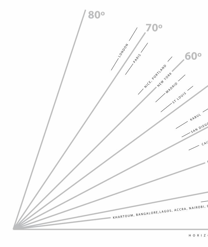
vi) Tilt the modules directly north or south towards the equator as described in section 2a. Tilt the modules at an angle from the flat position, depending where you are in the world. Appendix 1 is a useful page you can tear out and use to check the angle. Generally speaking, countries on the same latitude (distance from the equator) will use the same tilt angle.
vii) Make sure the modules are secure to withstand high winds.
b) Mounting the Lumina light fittings (load).i) Remove both end covers, the diffuser and the lamp, if fitted (Figure 4 & 5).
Figure 1: Checking cable length between SPCC10 and the Solar Module
Figure 2: Fixing the mounting bracket to the Solar module
Figure 3: Fixing the solar module to the ceiling using the supplied coach screw
Figure 5: Disassembly of the Lumina light fitting
Figure 4: Removing of Lumina screw cap

ii) Strip 5mm of insulation from the cable. Feed the cable through the entry hole in the base and connect to the terminal block marked + and - observing correct polarity. (white/black to‘+’, white to ‘-’). Fit the cable clamp with the two small screws provided with the Lumina (Figure 6 &7)
iii) Replace the large end cover over the electronics and secure to the base using two screws supplied.
iv) Using a further two screws (supplied), attach the light to the wall or ceiling as required (Figure 8).
v) Insert the lamp until it clicks into place (Figure 9).
vi) Slide on the clear lens (diffuser) and attach the small end cover to complete the installation (Figure 10).
vii) Safety Although the standard Lumina light is designed to operate from an input voltage of 12 VDC, much higher AC voltages are present on the internal circuit board and at the lamp socket during operation, and so due care should be taken. The Lamps contain mercury vapour, which could be harmful if the lamp is broken and the gases inhaled. Due care and attention should be taken when disposing of expired lamps.
Figure 8: Attaching Lumina to wall
Figure 9: Lamp insertion
Figure 10: Closing the Lumina cap
Figure 6: Stripping of cable for connection to the Lumina
Figure 7: Fixing the cable to the Luminax
Figure 8: Attaching Lumina to wall
80º70º
60º
50º
40º
30º
20º
15º
0º
NI C
E , PO
R T L A ND
MA D R I D
K A B U L
C A I R O
H O R I Z O N T A L G R O U N D
L ON
DO
N
P AR I S
K H A R T O U M , B A N G A L O R E , L A G O S , A C C R A , N A I R O B I , D A R E S S A L A A MH A R A R E MINIMUM
TILT
NE W
YO
R K
M I A M I
S A N D I E G O
S T L O U I S
Angle of solar module from the ground
If in the northern hemisphere: face your panel directly south.
If in the southern hemisphere: face your panel directly north.
Appendix 1. solar module tilt angle.
70ºW
all
Ground
Sola
r mod
ule
45º
Wal
l
Ground
Solar module
15º Wal
l
Ground
Solar module
70º
Wal
l
Ground
Sola
r mod
ule
45ºW
all
Ground
Solar module
15º Wal
l
Ground
Solar module
70º
Wal
l
Ground
Sola
r mod
ule
45º
Wal
l
Ground
Solar module
15º Wal
l
Ground
Solar module
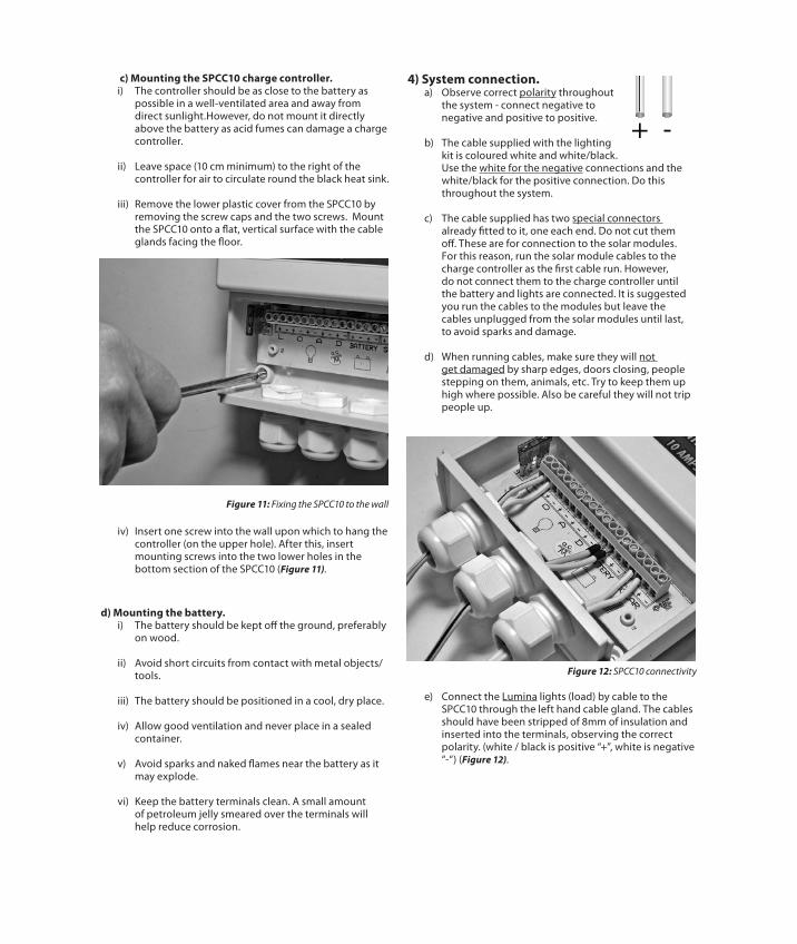
c) Mounting the SPCC10 charge controller.i) The controller should be as close to the battery as possible in a well-ventilated area and away from direct sunlight.However, do not mount it directly above the battery as acid fumes can damage a charge controller.
ii) Leave space (10 cm minimum) to the right of the controller for air to circulate round the black heat sink.
iii) Remove the lower plastic cover from the SPCC10 by removing the screw caps and the two screws. Mount the SPCC10 onto a flat, vertical surface with the cable glands facing the floor.
iv) Insert one screw into the wall upon which to hang the controller (on the upper hole). After this, insert mounting screws into the two lower holes in the bottom section of the SPCC10 (Figure 11).
d) Mounting the battery.i) The battery should be kept off the ground, preferably on wood.
ii) Avoid short circuits from contact with metal objects/ tools.
iii) The battery should be positioned in a cool, dry place.
iv) Allow good ventilation and never place in a sealed container.
v) Avoid sparks and naked flames near the battery as it may explode.
vi) Keep the battery terminals clean. A small amount of petroleum jelly smeared over the terminals will help reduce corrosion.
4) System connection.a) Observe correct polarity throughout the system - connect negative to negative and positive to positive.
b) The cable supplied with the lighting kit is coloured white and white/black. Use the white for the negative connections and the white/black for the positive connection. Do this throughout the system.
c) The cable supplied has two special connectors already fitted to it, one each end. Do not cut them off. These are for connection to the solar modules. For this reason, run the solar module cables to the charge controller as the first cable run. However, do not connect them to the charge controller until the battery and lights are connected. It is suggested you run the cables to the modules but leave the cables unplugged from the solar modules until last, to avoid sparks and damage.
d) When running cables, make sure they will not get damaged by sharp edges, doors closing, people stepping on them, animals, etc. Try to keep them up high where possible. Also be careful they will not trip people up.
e) Connect the Lumina lights (load) by cable to the SPCC10 through the left hand cable gland. The cables should have been stripped of 8mm of insulation and inserted into the terminals, observing the correct polarity. (white / black is positive “+”, white is negative “-“) (Figure 12).
Figure 12: SPCC10 connectivity
Figure 11: Fixing the SPCC10 to the wall

Figure 13: Removing of battery cable fuse before connectivity
f) Remove the fuse from the ready-assembled battery cable before connection. Connect the battery cable to the charge controller, then to the battery. The red clip goes on the red/positive terminal of the battery, the black clip on the negative (Figure 13).
g) Connect the solar module’s cable into the charge controller but do not connect the plugs on the rear of the solar modules yet. (Alternatively, cover the solar modules with a blanket to prevent them generating power).
h) Ensure all the wiring is secure using the cable clips and cable ties provided.
i) Power up the system by fitting the fuse in the battery cable (Figure 14).
j) Check the SPCC10 charge controller, one of the LEDs should be lit.
k) Turn on each of the Lumina lights and check they all work.
l) Turn off all the Luminas. Plug in the cables at the back of the solar modules (or remove the blanket covering them). This will now charge the battery during the day.
m) It is highly recommended that you leave the system with the lights off and charging the battery from the solar modules until the battery is fully charged. The state of charge is indicated by the LEDs on the SPCC10 charge controller. Once the ‘Full’ LED lights, the system can then be used by turning on the lights.
n) The charge controller will protect the battery from over-charging by automatically disconnecting the solar modules when the battery is full. It will automatically reconnect them as the charge gets used again.
o) The charge controller will automatically protect the battery from over-discharge by disconnecting the lights if the battery gets too low. If this happens, you can as an emergency, turn off all the lights, wait a short while and press the reset button on the SPCC10. You may then be able to turn on one light for a few minutes longer.
p) If you find the lights go off sooner than you want, you should consider saving power by only turning them on when needed. If you still have a problem, consult the troubleshooting guide overleaf.
Figure 14: Battery connectivity
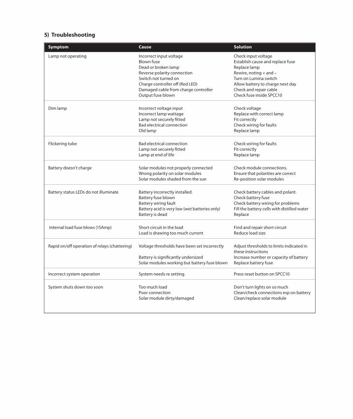
Symptom Cause Solution
Lamp not operating Incorrect input voltage Check input voltage Blown fuse Establish cause and replace fuse Dead or broken lamp Replace lamp Reverse polarity connection Rewire, noting + and – Switch not turned on Turn on Lumina switch Charge controller off (Red LED) Allow battery to charge next day Damaged cable from charge controller Check and repair cable Output fuse blown Check fuse inside SPCC10
Dim lamp Incorrect voltage input Check voltage Incorrect lamp wattage Replace with correct lamp Lamp not securely fitted Fit correctly Bad electrical connection Check wiring for faults Old lamp Replace lamp
Flickering tube Bad electrical connection Check wiring for faults Lamp not securely fitted Fit correctly Lamp at end of life Replace lamp
Battery doesn’t charge Solar modules not properly connected Check module connections. Wrong polarity on solar modules Ensure that polarities are correct Solar modules shaded from the sun Re-position solar modules
Battery status LEDs do not illuminate Battery incorrectly installed. Check battery cables and polarit. Battery fuse blown Check battery fuse Battery wiring fault Check battery wiring for problems Battery acid is very low (wet batteries only) Fill the battery cells with distilled water Battery is dead Replace
Internal load fuse blows (15Amp) Short circuit in the load Find and repair short circuit Load is drawing too much current Reduce load size
Rapid on/off operation of relays (chattering) Voltage thresholds have been set incorrectly Adjust thresholds to limits indicated in these instructions Battery is significantly undersized Increase number or capacity of battery Solar modules working but battery fuse blown Replace battery fuse
Incorrect system operation System needs re setting. Press reset button on SPCC10
System shuts down too soon Too much load Don’t turn lights on so much Poor connection Clean/check connections esp on battery Solar module dirty/damaged Clean/replace solar module
5) Troubleshooting
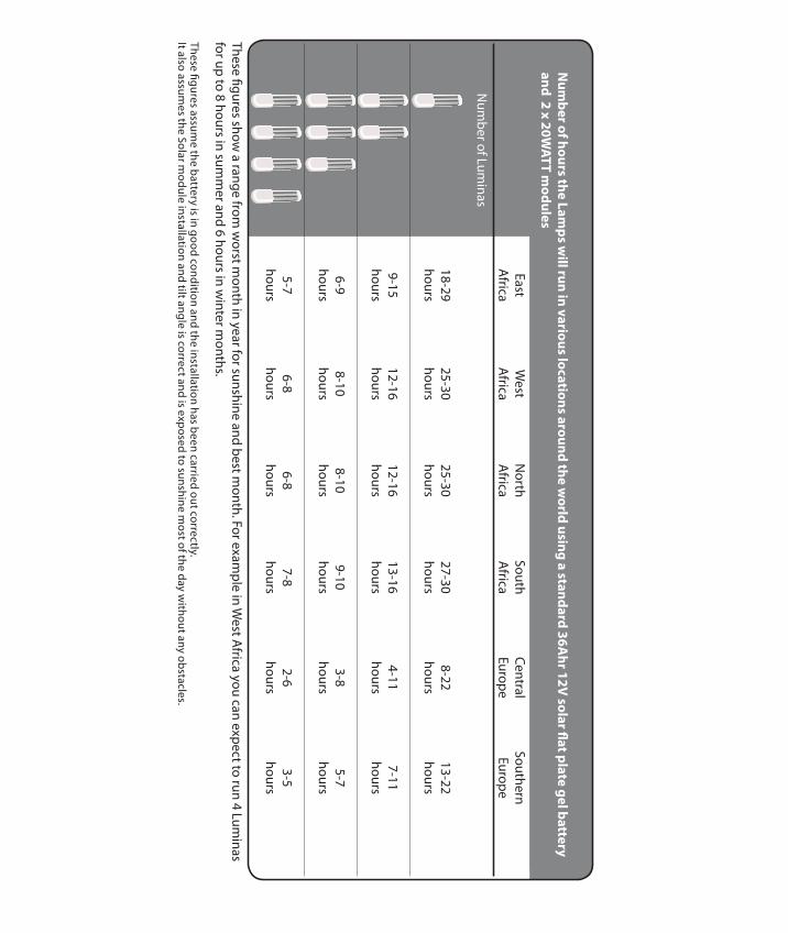
These figures show a range from
worst m
onth in year for sunshine and best month. For exam
ple in West A
frica you can expect to run 4 Luminas
for up to 8 hours in summ
er and 6 hours in winter m
onths.
East
West
North
SouthCentral
Southern
Africa
Africa
Africa
Africa
EuropeEurope
Num
ber of Luminas
18-29
25-3025-30
27-308-22
13-22
hourshours
hourshours
hourshours
9-15
12-1612-16
13-164-11
7-11
hourshours
hourshours
hourshours
6-9
8-108-10
9-103-8
5-7
hourshours
hourshours
hourshours
5-7
6-86-8
7-82-6
3-5
hourshours
hourshours
hourshours
Num
berofhoursthe
Lamps
willrun
invarious
locationsaround
thew
orldusing
astandard
36Ahr12V
solarflatplategelbattery
and2
x20W
ATTm
odules
These figures assume the battery is in good condition and the installation has been carried out correctly.
It also assumes the Solar m
odule installation and tilt angle is correct and is exposed to sunshine most of the day w
ithout any obstacles.
Sollatek (UK) Ltd Unit 10 Poyle 14 Newlands drive, Poyle, Slough SL3 0DX, U K.
Tel: International: +44 1753 688300 National: 01753 688300
Fax: International: +44 1753 685306 National: 01753 685306
E-mail: [email protected]
Internet:www.sollatek.com www.sollatek.com
P R O VIDING
CLE
AN
RELIABLE POW
ER
WO
RLD
WID E
Sollatek provides you with full back up support and a two year worldwide warranty on all products, with local support in over twenty countries worldwide.
SLK4 user manual Nov 08Artwork ID: 10910037 Stock code: 74137830
All weights and dimensions are approximate. Specifications are subject to change without prior notice. ©Sollatek (UK) Limited 2007. All Rights Reserved. SOLLATEK and the SOLLATEK device are the trade marks of the Sollatek group of companies.
TWO YEAR WORLDWIDE WARRANTY (subject to terms and conditions).
ISO9001: 2000 accredited company
s o l a r s y s t e m s
™