Slitting Cutter - korloy.com Slitting cutter.pdf · - Main application for slotting and parting off...
4
- Optimal chip breaker design and N/L edge treatment make to increase cutting edge rigidity. - Exact position of V-groove part enables to powerful clamping. - Secure clamping system guarantees smooth cutting force with the positive geometry. - Main application for slotting and parting off machining. Features No: 206 Parting Slotting Slitting
Transcript of Slitting Cutter - korloy.com Slitting cutter.pdf · - Main application for slotting and parting off...

- Optimal chip breaker design and N/L edgetreatment make to increase cutting edge rigidity.
- Exact position of V-groove part enables topowerful clamping.
- Secure clamping system guarantees smoothcutting force with the positive geometry.
- Main application for slotting and parting offmachining.
Features
No: 206
Parting Slotting Slitting

Slitting cutterClamping system | Chip control | insert | Code system
Clamping system
The assembly of insert
2
Slitting cutter code system
Using SP Insert Slitting cutterSide cutter
SP SInsert width
03
Arbor size(ø)
22- R : Weldon Shank type- F : Drive Flange type- R/F : Interchangeably
(WS type/ DF type)
R
Cutter diameter(ø)
100
Number of tooth
09
Chip control
FF1
F2
Low feed High feed
Fitting the insert
SW17P
SW17P
Removing the insert
KEYInsertwidth
2.0 ~ 3.0 SW17P
Clamping part
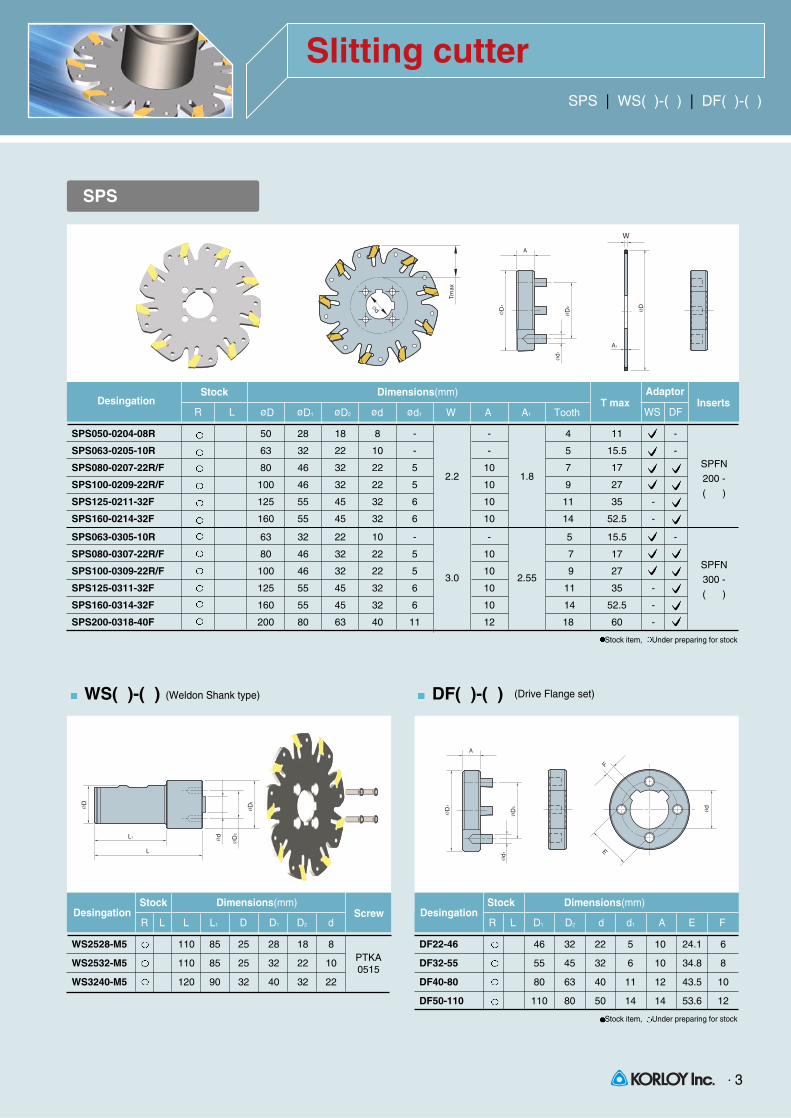
Slitting cutterSPS | WS( )-( ) | DF( )-( )
3
SPS
SPS050-0204-08R 50 28 18 8 - - 4 11 -
SPS063-0205-10R 63 32 22 10 - - 5 15.5 -
SPS080-0207-22R/F 80 46 32 22 5 10 7 17
SPS100-0209-22R/F 100 46 32 22 5 10 9 27
SPS125-0211-32F 125 55 45 32 6 10 11 35 -
SPS160-0214-32F 160 55 45 32 6 10 14 52.5 -
SPS063-0305-10R 63 32 22 10 - - 5 15.5 -
SPS080-0307-22R/F 80 46 32 22 5 10 7 17
SPS100-0309-22R/F 100 46 32 22 5 10 9 27
SPS125-0311-32F 125 55 45 32 6 10 11 35 -
SPS160-0314-32F 160 55 45 32 6 10 14 52.5 -
SPS200-0318-40F 200 80 63 40 11 12 18 60 -
DesingationøD øD1 øD2 ød ød1 W A A1 Tooth
Stock Dimensions(mm)T max Inserts
Adaptor
R L WS DF
Stock item, Under preparing for stock
Stock item, Under preparing for stock
2.2 1.8
3.0 2.55
WS( )-( ) (Weldon Shank type) (Drive Flange set)DF( )-( )
WS2528-M5 110 85 25 28 18 8
WS2532-M5 110 85 25 32 22 10
WS3240-M5 120 90 32 40 32 22
DesingationL L1 D D1 D2 d
Stock Dimensions(mm)Screw
R L
PTKA0515
DF22-46 46 32 22 5 10 24.1 6
DF32-55 55 45 32 6 10 34.8 8
DF40-80 80 63 40 11 12 43.5 10
DF50-110 110 80 50 14 14 53.6 12
DesingationD1 D2 d d1 A E F
Stock Dimensions(mm)
R L
SPFN
200 -
( )
SPFN
300 -
( )

Slitting cutterSPFN insert | Recommended cutting condition | Cutting depth
SPFN insert
HEAD OFFICEHolystar B/D 953-1, Doksanbon-Dong, Geumchun-Gu, Seoul, KoreaTEL : +82 2 522 3181 FAX : +82 2 522 3184, +82 2 3474 4744WEB:www.korloy.com
CHEONGJU FACTORY53-16, Songjeong-Dong, Hungduk-Gu, Chengju, Chungcheongbuk-Do, KoreaTEL:+82 43 262 0141 FAX:+82 43 262 0146E-MAIL:[email protected]
JINCHEON FACTORY767-1, Gwanghyewon-Ri, Gwanghyewon-Myon, Jincheon-Gun, Chungcheongbuk-Do, KoreaTEL:+82 43 535 0141 FAX:+82 43 535 0144
SPFN200-N 2.2 0.2
SPFN300-N 3.0 0.2
Desingation
PC3525 PC3535 PC9530 PC215K NCM325 NCM335 ST30A
Dimensions(mm)Grade
PVD CVD Uncoated
W R
Stock item, Under preparing for stock
T/D = 10%(T:cutting depth)
Recommended cutting condition
Workpiece
P
M
K
Low carbon steel / Alloy steel
High carbon steel / Alloy steel
High alloy steel
Stainless steel
Cast iron
180HB PC3525 210 (170 ~ 250) 0.13 ~ 0.30
180 ~ 260HB PC3525 150 (100 ~ 200) 0.13 ~ 0.25
260 ~ 350HB PC3525 120 (80 ~ 170) 0.10 ~ 0.17
150 ~ 300HB PC9530 160 (120 ~ 200) 0.10 ~ 0.22
T/ S 350N/mm2 PC215K 110 (70 ~ 150) 0.10 ~ 0.25
vc(m/min) fz(mm/t)Hardness Grade
Correction factor of fz(mm/t) as cutting depth
50 ~ 100 Standard =1.0 0.07 0.15
2.5 3.7 0.26 0.56
5 2.5 0.18 0.38
10 1.8 0.13 0.27
15 1.5 0.11 0.23
20 1.3 0.09 0.20
25 1.2 0.08 0.18
Factor fz (mm/t)Machining T/D (%)
Correction factor by T/D(%) : The value of chip thickness rate as feed (fz)
Chip thickness (Hm) : > >
Hm
30%
20%10%
5%T
D
Fz