Slip Detection and Recovery for Quadruped Robots · 2020-07-02 · Slip Detection and Recovery for...
16
Slip Detection and Recovery for Quadruped Robots Michele Focchi, Victor Barasuol, Marco Frigerio, Darwin G. Caldwell, Claudio Semini Abstract What should a legged robot do when it slips? When traction is lost, the locomotion can be irreversibly hampered. Being able to detect slippage at the very beginning and promptly recover the traction is crucial for body stability and can make the difference in a situation where falling is not an option. Indeed, the major- ity of locomotion controllers and state estimation algorithms rely on the assumption that the stance feet are not slipping. The following work presents a methodology for slip detection and estimation of the friction parameters, plus a recovery strategy which exploits the capabilities of a whole body controller, implemented for locomo- tion, which optimizes for the ground reaction forces (GRFs). The estimation makes use only of proprioceptive sensors (no vision). Even though the essence of the ap- proach is quite general, the implementation is specialized for the quadruped robot HyQ. Simulation results demonstrate the effectiveness of the proposed approach while walking on challenging terrains (a slippery ramp or an ice slab). Keywords: slip detection, slip recovery, locomotion, quadruped, whole body con- trol. 1 Introduction Being able to deal with slippage is of great importance for legged robots which are meant to traverse unstructured terrains. In particular, a strategy for detecting slippage and recover from it, becomes crucial when whole body inverse dynamics approaches are implemented for robot control [1], [18], [14]. Actually, they rely on the assumption that the stance feet constraints are not violated (e.g. they are not moving or are supposed to move very little [8]). Indeed, a violation of the stance Dept. of Advanced Robotics, Istituto Italiano di Tecnologia (IIT), via Morego, 30, 16163 Genova e-mail: [email protected],[email protected],marco.frigerio@ iit.it,[email protected],[email protected] 1
Transcript of Slip Detection and Recovery for Quadruped Robots · 2020-07-02 · Slip Detection and Recovery for...

Slip Detection and Recovery for QuadrupedRobots
Michele Focchi, Victor Barasuol, Marco Frigerio, Darwin G. Caldwell, ClaudioSemini
Abstract What should a legged robot do when it slips? When traction is lost, thelocomotion can be irreversibly hampered. Being able to detect slippage at the verybeginning and promptly recover the traction is crucial for body stability and canmake the difference in a situation where falling is not an option. Indeed, the major-ity of locomotion controllers and state estimation algorithms rely on the assumptionthat the stance feet are not slipping. The following work presents a methodologyfor slip detection and estimation of the friction parameters, plus a recovery strategywhich exploits the capabilities of a whole body controller, implemented for locomo-tion, which optimizes for the ground reaction forces (GRFs). The estimation makesuse only of proprioceptive sensors (no vision). Even though the essence of the ap-proach is quite general, the implementation is specialized for the quadruped robotHyQ. Simulation results demonstrate the effectiveness of the proposed approachwhile walking on challenging terrains (a slippery ramp or an ice slab).
Keywords: slip detection, slip recovery, locomotion, quadruped, whole body con-trol.
1 Introduction
Being able to deal with slippage is of great importance for legged robots whichare meant to traverse unstructured terrains. In particular, a strategy for detectingslippage and recover from it, becomes crucial when whole body inverse dynamicsapproaches are implemented for robot control [1], [18], [14]. Actually, they rely onthe assumption that the stance feet constraints are not violated (e.g. they are notmoving or are supposed to move very little [8]). Indeed, a violation of the stance
Dept. of Advanced Robotics, Istituto Italiano di Tecnologia (IIT), via Morego, 30, 16163 Genovae-mail: [email protected],[email protected],[email protected],[email protected],[email protected]
1

2 M.Focchi et al.
constraints makes the inverse dynamics compute joint torques which are not phys-ically meaningful anymore. This would result in: (i) errors in the realization of thedesired body wrench (because the slip limits the amount of tangential force that theground is able to deliver) (ii) degeneration of the support triangle. These two factswould eventually lead to a loss of stability even in case of very slow motions. On thesame line, kinematic-based state estimation or odometry techniques [3], [6], whichrely on the assumption that none of the stance feet is slipping, are prone to drift ifthe amount of slip is relevant (or if there is a compliance between the base and theground which is not modelled). Even if the controller incorporates the optimizationof the ground reaction forces, there are two types of uncertainties which can causeslippage during locomotion:
1. Uncertainty on the estimate of the surface normal n. This is commonly estimatedby vision [17] or by fitting a plane (gradient-based terrain detection) through thefeet that are on the ground (stance feet) [26]. The fitting plane can be a very crudeapproximation of the terrain surface inclination which can have local discontinu-ities (e.g. like the ramp illustrated in Fig. 4). Any deviation from a planar shaperesults in errors in the estimation of the inclination of the surface which is underthe foot at the moment of the touch-down.
2. Uncertainty on the friction coefficient µ. Most of the times µ cannot be known inadvance and is commonly inferred according to semantic information (e.g. ice)coming from vision [22].
An earlier work on slip recovery is from Takemura [26], who presented both along term and a short term strategy for slip recovery. The former aims to change gaitfrequency and stride length when approaching slippery surfaces. However, chang-ing locomotion parameters to address slippage can be successful only on terrainwith limited roughness and moderate slipperiness. Conversely, if very challengingenvironment is considered (e.g crossing a river or walking on ice), the occurrenceof slippage might result in unrecoverable loss of stability because any other foot-step can be infeasible. A short term strategy is needed in these cases. At this extent,Takemura proposes to instantaneously add a force (at the occurrence of slippage) tohave the ground reaction forces back in the friction cone. This approach has severalshortcomings: (1) it is based on the idea that the normal is properly estimated; (2)the required force might not be necessarily realizable at the foot, since the groundreaction force is the result of the robot motion in interaction with the environment.More precisely, the GRFs can only be controlled to a limited extent (e.g. creatinginternal forces) in the null-space of the contact constraints. In addition to this (instatic conditions) the maximum applicable total normal force is constrained by therobot weight.
To address the above limitations we propose a short term slip recovery strategy,which is built on top of a whole body controller [9], [10]. In essence the controllerwe use, is formulated as a QP problem where the goal is to realize a certain bodywrench while optimizing for ground reaction forces (decision variables). We addedinequality constraints to the problem to obtain forces that obey friction cones limits,additionally accounting for the fact that the ground can only push and not pull (uni-

Slip Detection and Recovery for Quadruped Robots 3
StartTrajectory Generation(body motion + swing)
If i is stanceincorporate it
back in odometry
NoEnd Estimate friction parameters
(moving average)
Whole body control
slip detection(algorithm 1)
If foot i is stance remove it from odometry
NSmooth
correction ofStill slipping?
Yes
Slip detection/recovery
can recover
slip?
Low level control
Terrain estimation
Yes
Freezing mode
No
Fig. 1 Slip recovery pipeline (blue blocks): detection, estimation and correction. The yellowblocks are: the body, feet trajectory generation and the high level control (whole body) and thelow level one (torque).
lateral constraints). The body wrench is the 6D vector of forces/moments comingfrom the body motion task that aims to track a specified trajectory for the CoM andthe trunk orientation.
In this context, assuming a reliable low level tracking of the joint torques andno external disturbances, a slippage can only occur if the controller uses a wrongestimate of the surface normal or of the friction coefficient. In fact, this results inGRFs which are out of the real friction cones (cf. Section 4.1). Therefore, differentlyfrom Takemura, instead of striving to apply the correct GRFs (which might notbe feasible), we propose to correct the estimate of the surface inclination and ofthe friction coefficient in order to allow the robot to apply forces which satisfy thefriction limits.
More recently, in one of the online videos 1, the BigDog robot demonstrated tosuccessfully recover from slipping on ice. However, to date, no experimental resultshave been published and no details have been reported on the repeatability of theused approach.
Within the context of legged robots, the main contribution of this paper is amethodology to: (1) detect slippage, (2) on-line estimate the friction coefficientµ and the normal n of the surface making use of only proprioceptive informa-tion (torque measurement and encoder readings) (3) on-line recovery from slip-page by smoothly accommodating (but in a short time interval) the value of thenormal used in the optimization to the estimated one. The whole slip recoverypipeline is graphically summarized in Fig. 1. We have implemented the slip de-tection/estimation/recovery strategy for a model of HyQ [24], a 80kg quadrupedrobot with point feet. HyQ is shown to perform a (statically stable) walk on a highlyslippery (flat) surface and on a moderately slippery ramp.
1 video available at http://www.youtube.com/watch?v=cNZPRsrwumQ

4 M.Focchi et al.
The applicability of this approach is limited to torque controlled robots equippedwith a high-level controller which optimizes for ground reaction forces. We willshow simulations where the slip is detected only in one leg and when there are atleast three legs in contact with the ground. A possible solution for the detection inthe case of more than two legs slipping is only drafted.
This paper is structured as follows: Section 2 presents a robust way to detectslippage, followed by Section 3 that illustrates the on-line estimation of the frictionparameters. Section 4 describes the implemented strategy to recover traction dur-ing slippage. Sections 5 and 6 contain the results of simulations with HyQ and theconclusions, respectively.
2 Slip detection
The approaches to address the problem of slip detection can be divided into two biggroups: force based and kinematic based approaches. The force based, require theavailability of a 6-axis force sensor which is usually located at the contact point (e.g.the foot-tip). If the friction coefficient is known in advance, the slippage could sim-ply be detected by checking if the ratio of the tangential/normal component of thecontact forces [20] is within the limit of static friction. When the friction coefficientµ is unknown, a possible strategy is to check the frequency content of the tangentialcontact force signal. As a matter of facts, in presence of slippage, a high frequencyripple in the force signal appears, due to the local stick-slip phenomena that occursbetween the contacting surfaces. First Holweg [15] and more recently Palli [21],claimed that, after performing a Fourier analisis (FFT) of the higher harmonics ofthe force signal, it was possible to recognize the deformations which precedes thereal slip. These approaches are of limited applicability to legged robots, becausethey need a high cost force/torque sensor to be attached to the foot tip. However,due to the repetitive impacts with the ground, in the long run, this can result in adamage of the sensor. Furthermore, during locomotion, the touchdown event cancreate discontinuities in the force signals and jeopardize the detection. As a matterof facts, it is not easy to measure the instant when the force oscillation, due to thetouch-down, has settled down, in order to have a detection without false positives.Conversely, a detection strategy based on kinematics, it preferable in the context oflegged robots where ground impacts are the order of the day.
A kinematic strategy can be implemented at the acceleration, velocity or positionlevel. In [26] Takemura considered slippage as an impulse-like leg acceleration, andattached accelerometers to the lower-leg links to detect slippage. A drawback of thisapproach is that accelerometers are usually affected by noise.
Alternatively, slippage could be estimated at the position level, by checking theinter-distances between the stance feet. Indeed slippage of one (or more) feet canbe detected if the mutual distance of the stance feet (which is set at the moment anew touchdown event occurs) changes within the duration of a single stance config-uration. However, when traction is lost the resulting acceleration will create also a

Slip Detection and Recovery for Quadruped Robots 5
velocity difference among the stance feet. Being the position the integral of velocitythis difference can be detected more promptly in velocity than in position. Thus, wepropose to check the slippage at the velocity level. It is important to underline thatthe choice of the frame in which the feet velocities are compared, directly affectsthe robustness of the approach. The most intuitive way is to check if the Cartesianvelocities of the stance feet are all zero in an inertial (world W) frame. However,expressing the foot velocity in the world frame (wxf ), requires an estimation of therobot base linear velocity wxb:
0 u wxf = wxb + wRb (bxf + bωb × bxf )︸ ︷︷ ︸b˙xf
(1)
where wRb ∈ R3×3 is the rotation matrix representing the orientation of the robotbase, while bωb is its angular velocity. bxf , bxf are, respectively, the position andvelocity of the foot expressed in the base frame (B). The angular velocity bωb canbe measured with reasonable accuracy by an on-board IMU sensor, while the baselinear velocity, as common practice in robotics, can be inferred through leg odom-etry or state estimation techniques [3]. Therefore, if we compare the feet velocitiesin the world frame, they are influenced by errors in the state estimation, which canresult into false positives in the slip detection. A more robust approach would be tocompare the feet velocities in the base frame (term b
˙xf in (1) which accounts alsofor the influence of the moving frame). The advantage of this, is that the kinematicsis always accurate because it directly depends on direct sensor measurements (e.g.encoders, gyro). Differently from the world frame case, the stance feet velocitiesb˙xf have to be equal in norm and direction (and opposite to the base linear velocity
bxb). Thus, in a manner similar to what a car ABS braking system is doing [2], afruitful strategy for slip detection is to compare the values of the norm vi = ‖b ˙xfi‖of the velocities of the stance feet and discriminate the outlier with appropriate sta-tistical tools. Henceforth, for the sake of brevity, we denote the norm with v and theassociated Cartesian vector with v.
One leg slip detection: Following, we present a pseudo-code implementation ofthe slip detection for one leg of a legged robot:
Algorithm 1 detectSlippageOneLeg()1: for each stance leg i do2: vel norm [i]← |bxfi
|3: end for4: M ← median(vel norm)5: for each stance leg i do6: legSlippingF lag[i]← abs(vel norm[i]−median) > th7: end for
At each control loop the median of the norms of the stance feet velocities iscomputed. The median will have a value in between the velocities of the non slippinglegs and the slipping one. The slipping leg will be the one with a velocity far from
6 M.Focchi et al.
the median beyond a certain margin th, that can be tuned experimentally. Duringlocomotion the detection algorithm is continuously checking, within the set of activestance legs, if there is any slippage. Whenever a slip is detected, if the leg was astance leg, this should be removed from the set of stance legs accounted in the stateestimation/odometry, while it can be incorporated back at the end of the slip (seeFig.1). This is crucial to prevent the corruption of the state estimate.
Multiple leg slip detection: A more subtle situation is when two legs are slippingat the same time. In this case, it is hard to detect with the median approach, who arethe slipping legs and who are the stance legs (we just know that they have pair-wise different velocities). In this case, checking which of the feet velocities vi arekinematically consistent with the base velocity bxb, could help us to discriminate theslipping legs. At this extent a short-time integration of the base linear acceleration(IMU) can be the only resort. It is known that integrating accelerometers is prone todrift but, for a limited time interval, the estimate should be accurate enough.
3 Surface normal and friction coefficient estimation
Once that the slip is in act, it is crucial to estimate the friction coefficient µ and thesurface normal n in the early milliseconds of slippage, in order to be able to apply acorrective action as described in Section 4.
Remark: Along the paper, we will not make a distinction between static anddynamic friction.
Firstly, we make the following assumptions:Assumption 1: The frictional properties of the surface around the foot are isotropic
(coefficient of friction equal in all directions).Assumption 2: when the leg starts to slip (it will start slow), it will cover a surface
where the normal is uniformly constant.Assumption 3: we assume no soft contact. Since the robot has point feet we can
neglect the influence of the rotational friction about the normal direction (more com-plex than the linear one because it depends on the size of the contact area).
We can get useful insights for the estimation considering the following facts:
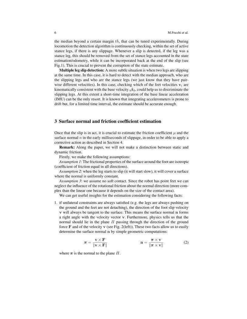
1. if unilateral constraints are always satisfied (e.g. the legs are always pushing onthe ground and the feet are not detaching), the direction of the foot slip velocityv will always be tangent to the surface. This means the surface normal n formsa right angle with the velocity vector v. Furthermore, physics tells us that thenormal should lie in the plane Π passing through the direction of the groundforce F and of the velocity v (see Fig. 2(left)). These two facts allow us to easilydetermine the surface normal n by simple geometric computations:
π =v × F
‖v × F‖n =
π × v
‖π × v‖(2)
where π is the normal to the plane Π .

Slip Detection and Recovery for Quadruped Robots 7
Fig. 2 (Left) Vector definitions for slip detection (for a generic foot on a slope). The red dot is thefoot location, Π is the plane where the ground reaction force F and the foot velocity vector v liewhile n is the estimated surface normal. (Right) Slip recovery definitions: n is the actual normalused in the controller. e is the axis of rotation to move n towards n while ∆θ is the correctionangle.
2. during the slipping motion, the ground force F is always lying on one edge ofthe friction cone. Therefore, while the foot is slipping, the angular distance φbetween F and n (see Fig. 2), can be an estimate of the real friction coefficient(µ = tan(φ)):
µ = tan(φ) =sin(φ)
cos(φ)=‖F× n‖F · n
(3)
To obtain a noise-free estimation of the normal n, we compute a moving averageon N samples, by using a parametric representation of the geodesic [12], while forthe friction coefficient µ we perform a moving average with linear weighting (lastsample is weighted most).
Observation: the value of µ found with this approach, represents a ”sample”of the friction coefficient in a certain direction. Depending on the way the frictionconstraints are implemented in the optimization (e.g. if the friction cone is approx-imated with an inscribed polyhedron to have linear constraints [25]) an appropriatescaling should be considered. For instance, in the case we approximate the conewith the inscribed pyramid, the estimated µ should be scaled by 1/
√2 which is the
ratio between the edge of the inscribed pyramid and the diameter of the cone.
4 Slip recovery
4.1 Dynamics of slippage
To obtain insights to draft a strategy for slip recovery it is useful to understand thedynamics of slippage.
1D case: Let us consider the simple case of a mass standing on a plane with fric-tion under the effect of a vertical force (Fig. 3(top)). We can model the contact as a

8 M.Focchi et al.
m m m m
(a) (b) (c) (d)
(a) (b) (c) (d)
Fig. 3 Slip dynamics: (top) 1D case (bottom) 3D case.
set of tiny bristles [13]. If an external force is applied to the mass which has a tangen-tial component Fextt the ”bristles” at the contact interface start to deform (b) and thefriction force with the plane Ff builds up until the breaking point |Ff | = µ|Fextn |is achieved, where the bristles start to slide over each other. From then onward theywill apply a constant resistance force Ff which is opposing the motion direction (c).The subsequent motion will depend on the mass dynamics (mdv/dt = Fextt − Ff )and any tangential component of Fext will increase the kinetic energy of the body,increasing the slippage. If Fextt is removed (d), the accumulated momentum willkeep the mass in motion but Ff will decelerate it until v = 0.
3D case: Consider now the case of a point foot on a frictional plane (Fig. 3(bot-tom)). In the situation (a), the ground reaction force F is able to balance the externalforce Fext and the body is in equilibrium (v = 0). If an external load is appliedwhich would require a force which is out of the friction cone to be balanced (b),the ground will be able to balance only with a F which is constrained to lie on theboundary of the cone (satisfying the relationship ‖Ft‖ = µ‖Fn‖). The foot willthen start moving because there is a net force (black) accelerating it.
Now, as long as v 6= 0, F will stay on the cone boundary and be opposing themotion. However, if the external force is applied inside the friction cone (c), by thecomposition of vectors, the net force will have a decelerating component that willslow down the slipping motion until v = 0 and the grip will be recovered (d). In thissituation Fext will balance again F and the contact will be stable.

Slip Detection and Recovery for Quadruped Robots 9
4.2 Smooth correction of friction parameters
When slippage occurs some action should be undertaken. The detection phase, il-lustrated in Section 2, has provided the estimated values of n and µ. The goal ofour short term slip recovery strategy is to make the actual surface inclination n (e.g.coming from a terrain estimation algorithm) and the friction coefficient µ, whichare used in the optimization, converge to the estimated ones. Once that n is set tothe appropriate direction (inside the cone), the slippage will naturally end-up aftera short transient, because the tangential component of the GRF (see Section 4.1)will ”make work” against the slipping motion and eventually stop it. To preventstep-wise torque discontinuities, we choose to perform the correction in a smoothfashion. The following recursive equations result in a smooth (1st order) conver-gence of n toward n and of µ toward µ:
∆θ(k) = atan (‖n× n‖/(n · n)) (4)ωθ(k) = e(k)Kn∆θ(k)
n(k + 1) = R(ωθ(k)dt)n(k)
µ(k + 1) = Kµµ+ (1−Kµ)µ
where ∆θ ∈ R is the angular error between n and n at time k (see Fig. 2 (right)).e ∈ R3 is the instantaneous rotation axis perpendicular to both n and n, and R(.) ∈R3×3 is the rotation matrix associated to the rotation vector ωθdt, which is obtainedby the Rodrigues’ formula. Kn and Kw are scalar gains to set the convergence ratesof n and µ, respectively. dt is the control loop duration.
Comment: It is well known that for a legged robot static/dynamic stability isdependent on the relationship between the CoM/ZMP and the support polygon [27].In the case the feet are standing on non-coplanar surfaces more elaborated com-putations should be carried out [4],[5]. In our work we assume that a stabilizingcontroller is available for the robot. The main goal of our approach is to eliminateslippage in a very short time interval (tens of ms) such that the support polygondoes not suffer significant changes and hence the robot stability is not affected. Ananalysis of the maximum amount of slippage which is tolerable in the context oflocomotion in order to preserve stability is out of the scope of this paper and will bepart of future works.
4.3 Freezing mode
If, during the slip recovery, the ground frictional force is not sufficient to reducethe slip velocity in a reasonable time (tens of ms) the slipping foot accumulates asignificant position error (with respect to the desired set-point). This can likely resultin significant degradation of the support polygon shape and possible loss of stability.

10 M.Focchi et al.
In this case, the last resort is to stiffen all the joints in the actual configuration andmake the robot behave like a ”wooden chair” (freezing mode in Fig. 1). In such away, a stable situation can be achieved even if all legs are slipping at the same time.Such a strategy is often successfully adopted by humans when slipping on ice.
5 Simulation results
In this section we show the effectiveness of the proposed slip detecion/estimation/recovery strategies simulating a walking of the dynamic model of the quadrupedHyQ [24] on very slippery surfaces. Namely, an ice slab with locally differentfrictional properties and a ramp. HyQ is 1 m long and weights 80 kg. Our sim-ulation environment is composed of two software packages. The first, called SL[23], is a multi-process application that provides a low level joint controller, a cus-tomizable trajectory generator, and a simulator. The robot-specific software, namelythe kinematics and dynamics engine, is implemented with RobCoGen which pro-vides an optimized C++ implementation of kinematics and dynamics [11] basedon spatial-vectors algebra and state-of-the-art numerical algorithms [7]. As far ascontact forces are concerned, the SL simulator implements a simple spring dampercontact model, together with a Coulomb model for friction. The simulation is basedpurely on rigid body dynamics, and as such it assumes ideal force sources at theactuated joints. To be consistent with a real implementation on the real robot, weestimate the ground reaction forces at the feet from torque measurements (HyQ isnot currently equipped with foot sensors). Both the loop for the optimization andthe rigid body simulation run at 1 kHz, which is the frequency of the low levelcontroller in the real platform. The state (position/orientation) of the robot base isestimated through leg odometry. The terrain inclination (roll and pitch) is computedby fitting a plane through the stance feet in a least-square fashion. The evaluation iscarried out after each touch-down event and this provides an initial estimate of thesurface normal n0 (see Fig. 1).
5.1 Ice patches
Figure 4(left)) shows a simulation of the robot walking on a slippery set of patcheslocated on flat ground. The patches have friction coefficients (µ = 0.15− 0.3) com-parable to the one of an ice-shoe contact [16]. Refer to [19], for different pairs ofmaterials. The robot has point feet and, thus, the friction forces are lower compareda robot which has flat feet. Indeed foot-ground contact in humanoids is usually mod-eled with 4 contact points located at the foot edges and slippage occurs when all ofthem break the contact. For a point foot morphology, walking on ice is challengingand slip recovery becomes crucial for the success of the task.

Slip Detection and Recovery for Quadruped Robots 11
Terrainestimationerror
Fig. 4 Simulation screen-shots of the robot walking on ice patches (left) and on a ramp (right). Inthe left plot, olive green lines represent the cone boundaries while the ground reaction forces aredepicted in light green. In the right plot n is converging toward n while the LF foot is slippingafter the touch-down.
With the ice patches simulation we want to show the robustness of our algorithmin estimating the friction coefficients of the different surfaces for all the 4 feets. Theblue/green patches have µ = 0.25, 0.2 while the white/red µ = 0.3, 0.15. They areall 75cm long. Our online video 2 shows that, without any slip recovery strategy, therobot falls at the very beginning after a few steps. Conversely, with the slip recoveryenabled, is able to traverse effectively all the patches, including the last ones whichhave lower friction coefficients. In Fig.5 we show the plots of the friction coefficientestimates for the 4 legs starting from µ = 0.6 which is the default value set at thebeginning of the simulation, in the controller. LF ,RF , LH andRH stand for Left-Front, Right-Front, Left-Hind and Right-Hind leg, respectively. For the estimatewe used a moving average window of 4 samples. The percent error in the estimationis always below 13%.
The slip recovery is beneficial also to avoid the accumulation of big estimationerrors in the leg odometry. From the same simulation data, the the upper plot ofFig. 6, shows that slippage created an estimation errors in the X direction (beforefalling) of 18 cm out of 50 cm walked, while using the slip recovery (lower plot)the maximum error is below 1 cm for the same time window.
Observation: In the enclosed video, a little slip is always present at the touch-down, that in principle should not occur, because the friction coefficient has beenproperly identified after stepping on the surface. This is due to the actual imple-mentation of the stance detection. When the swing foot touches the ground it mustapply a force beyond a certain threshold, to trigger the stance and to start optimizingthe force. This little force (before the trigger) is not optimized and it causes a littleslippage, which however is immediately recovered.
2 video available at https://youtu.be/Hrwi9-411AM

12 M.Focchi et al.
0
0.2
0.4
0.6
µ
LF RF LH RH
0 20 40 60 800
10
20Est.error[%
]
Time [s]
Fig. 5 Friction coefficients estimation for the 4 legs in the ice patches simulation. (Upper plot)solid lines are the estimated µ, dashed lines are the ground truth. (Lower plot) are the percentestimation errors.
−0.01
0.02
0.05
0.08
[m]
errx erry errz
0 5 10 15 20−0.01
0.02
0.05
0.08
Time [s]
[m]
0 5 10 15 200
0.3
0.6errx erry errz covered distance
Fig. 6 Plot of the Cartesian components of the odometry error, without (upper plot) and with(lower plot) slip recovery. The black line is the covered distance (right ordinate).
5.2 Slippery ramp
A transition from walking on flat terrain to a ramp (inclination 0.25 rad) is a goodtemplate to demonstrate the effectiveness of the algorithm in estimating the surfacenormal. Indeed, in the moment in which the robot is standing with only the front feeton the ramp, there is a big error (see Fig. 4 (right)) on the terrain inclination estimate.This results in a wrong estimation of the surface normal n which is set perpendicular

Slip Detection and Recovery for Quadruped Robots 13
Fig. 7 Slip event for the LF foot at the touch-down (ramp simulation). (First 3 upper plots) Carte-sian components of the surface normal where: n is the actual value, n is the estimated value andngt is the ground truth (from simulation). (Lower plot) the blue line depicts the friction cone vi-olation (in a [0-1] range) while the red line is the torque in the knee joint of the RH leg (stance).The estimation phase is shaded in red, while the correction phase is in blue.
to the estimated plane. If the surface is slippery enough (we set µ = 0.5) the frontlegs will slip and the slip recovery intervention is necessary to climb the ramp. InFig. 7 we magnify one slip event for the LF leg after the swing phase. The slipis detected at time t = 28ms, the estimation phase is shaded in red, while thecorrection phase is in blue. The slip transient ends at t = 80ms. In the upper plots,we show the convergence of n to the estimated value n while ngt is the groundtruth. The lower plot shows that the friction cone constraint is violated (in a strictsense) for the whole slippage situation (time interval t = 28−80ms). We underlinethat the torques of the stance legs (e.g. cf. the knee ofRH in Fig. 7(bottom)), do notsuffer from step-wise discontinuity, because of the smooth correction implementedfor n and µ.
Differently from Fig. 7 which shows the LF foot slipping after a swing phase,Fig. 8 shows a slip occurring during the body motion where the LF leg is in stance.The upper plot shows the velocities (norm) v of the feet while the lower one plotsboolean variables that tell which leg is slipping. Around t = 170ms the LF footstarts to slip and this is visible looking at its velocity which significantly differs fromthe ones of the other feet. The picture also shows that from the point of detection,thanks to the recovery action the slip terminates (the norm of the velocity goes backto the values of the other feet velocities) in less than 40ms.

14 M.Focchi et al.
0
0.5
1
footvelocity
(norm
)[m
/s]
LF RF LH RH
0 250 500 750 10000
0.5
1
SlippingFlag
Time [ms]
Fig. 8 Slip event for the LF leg during the body motion. (Upper) plot of the velocity (norm) v ofthe feet. (Lower) boolean flags which monitor which leg is slipping.
6 Conclusions and future works
We presented a methodology to detect slippage and estimate the relevant frictionparameters together with a short term strategy to recover from slippage during lo-comotion. The detection is based on kinematic measurement (plus the trunk angularvelocity) and, in the context of legged robots, is more suitable than a force-based ap-proach which involves the use of 6 axis force/torque sensors at the foot-tips. Havingan idea of the friction properties of the terrain during locomotion can be also usefulto set different level of ”cautiousness”, selecting more or less conservative gaits ac-cording to the situation at hand. On the other hand, the recovery strategy (which wasable to reduce slippage in less than 40ms), was implemented at the force level. Theidea behind the strategy was to correct the surface normal toward the estimated oneresulting in GRFs which were back inside the real friction cone. The slip recoverystrategy has been demonstrated to be essential for locomotion on very slippery sur-faces, or in situations (ramp) where the terrain inclination was wrongly estimated.
In future works we plan to speed-up the recovery action by setting (in the opti-mization) constraints on the tangential component on the GRF in order to ”help” thefrictional force in decelerating the slipping foot. We are aware that with the actualimplementation, the estimated friction coefficient can only decrease. Indeed, if therobot enters in a less slippery terrain after coming from a slippery one, it will keepthe previous friction coefficient which will be too conservative.
In the future, we are planning to fuse the actual approach with semantic informa-tion coming from vision. according to the terrain the robot is traversing the purposeof vision is to provide a default value for the friction coefficient together with anestimate of its ”difficulty”.

Slip Detection and Recovery for Quadruped Robots 15
Finally, we plan to perform extensive experimental validation of the proposedapproach on the real robot platform (HyQ). In particular we are planning to make itwalk on slippery slopes and Teflon patches.
References
[1] Y. Abe, M. da Silva, and J. Popovic. Multiobjective control with frictionalcontacts. ACM SIGGRAPH/Eurographics symposium on Computer animation,pages 249–258, 2007.
[2] A. a. Aly. An Antilock-Braking Systems (ABS) Control: A Technical Review.Intelligent Control and Automation, 02(03):186–195, 2011.
[3] M. Bloesch, M. Hutter, M. Hoepflinger, S. Leutenegger, C. Gehring, C. D.Remy, and R. Siegwart. State Estimation for Legged Robots-Consistent Fusionof Leg Kinematics and IMU. Robotics: Science and Systems, 2012.
[4] T. Bretl and S. Lall. Testing static equilibrium for legged robots. IEEE Trans-actions on Robotics, 24(4):794–807, 2008.
[5] S. Caron, Q.-c. Pham, and Y. Nakamura. Leveraging Cone Double Descrip-tion for Multi-contact Stability of Humanoids with Applications to Statics andDynamics. Robotics: Science and Systems, 2015.
[6] A. Chilian, H. Hirschmuller, and M. Gorner. Multisensor data fusion for robustpose estimation of a six-legged walking robot. IEEE International Conferenceon Intelligent Robots and Systems, pages 2497–2504, 2011.
[7] R. Featherstone. Rigid Body Dynamics Algorithms. Springer US, Boston, MA,2008.
[8] S. Feng, X. Xinjilefu, W. Huang, and C. G. Atkeson. 3D Walking Based onOnline Optimization. 13th IEEE-RAS International Conference on HumanoidRobots, 2013.
[9] M. Focchi, A. Del Prete, I. Havoutis, R. Featherstone, D. Caldwell,and C. Semini. High-slope Terrain Locomotion for Torque-ControlledQuadruped Robots. Technical report, https://hal.archives-ouvertes.fr/hal-01137225/document, 2015.
[10] M. Focchi, A. Prete, I. Havoutis, R. Featherstone, D. G. Caldwell, andC. Semini. Ground Reaction Forces Control for Torque-Controlled QuadrupedRobots. IEEE International Conference on Intelligent Robots and Systems:Workshop on Whole-Body Control for Robots in the Real World, 2014.
[11] M. Frigerio, J. Buchli, and D. G. Caldwell. Code generation of algebraicquantities for robot controllers. IEEE International Conference on IntelligentRobots and Systems, pages 2346–2351, Oct. 2012.
[12] C. Gramkow. On averaging rotations. Journal of Mathematical Imaging andVision, 15(1-2):7–16, 2001.
[13] D. a. Haessig and B. Friedland. On the Modeling and Simulation of Friction.American Control Conference, pages 1256–1261, 1990.

16 M.Focchi et al.
[14] A. Herzog, L. Righetti, F. Grimminger, P. Pastor, and S. Schaal. Balancing ex-periments on a torque-controlled humanoid with hierarchical inverse dynam-ics. In IEEE/RSJ International Conference on Intelligent Robots and Systems,pages 981–988. IEEE, 2014.
[15] E. Holweg, H. Hoeve, W. Jongkind, L. Marconi, C. Melchiorri, andC. Bonivento. Slip detection by tactile sensors: algorithms and experimen-tal results. IEEE International Conference on Robotics and Automation,09(April):3234–3239, 1996.
[16] I. Izumi, T. Nakamura, and R. L. Sack. Snow Engineering: Recent Advances:Proceedings of the third international conference, Sendai, Japan, 26-31 May1996. CRC Press, 1997.
[17] K. Klasing, D. Althoff, D. Wollherr, and M. Buss. Comparison of surfacenormal estimation methods for range sensing applications. IEEE InternationalConference on Robotics and Automation, pages 3206–3211, 2009.
[18] S. Kuindersma, F. Permenter, R. Tedrake, and A. Bu. An Efficiently SolvableQuadratic Program for Stabilizing Dynamic Locomotion. IEEE InternationalConference on Robotics and Automation, pages 2589–2594, 2014.
[19] D. R. Lide. CRC Handbook of Chemistry and Physics, 94th Edition, vol-ume 53. CRC Press, 2013.
[20] C. Melchiorri. Slip detection and control using tactile and force sensors.IEEE/ASME Transactions on Mechatronics, 5(3):235–243, 2000.
[21] G. Palli, L. Moriello, U. Scarcia, and C. Melchiorri. Development of an op-toelectronic 6-axis force/torque sensor for robotic applications. Sensors andActuators A: Physical, 220:333–346, 2014.
[22] R. B. Rusu. Semantic 3d object maps for everyday manipulation in humanliving environments. PhDThesis, 24(4):345–348, 2010.
[23] S. Schaal. The SL simulation and real-time control software package.Technical Report, (Online) Accessed August 2015 at \textit{http://www-clmc.usc.edu/publications/S/schaal-TRSL.pdf}, 2006.
[24] C. Semini, N. G. Tsagarakis, E. Guglielmino, M. Focchi, F. Cannella, andD. G. Caldwell. Design of HyQ - a hydraulically and electrically actuatedquadruped robot. Proceedings of the Institution of Mechanical Engineers, PartI: Journal of Systems and Control Engineering, 225(6):831–849, Aug. 2011.
[25] D. Stewart and J. Trinkle. An implicit time-stepping scheme for rigid bodydynamics with Coulomb friction. IEEE International Conference on Roboticsand Automation, 1, 2000.
[26] H. Takemura, M. Deguchi, J. Ueda, Y. Matsumoto, and T. Ogasawara. Slip-adaptive walk of quadruped robot. Robotics and Autonomous Systems,53(2):124–141, Nov. 2005.
[27] M. Vukobratovic, A. A. Frank, and D. Juricic. On the stability of biped loco-motion. IEEE transactions on bio-medical engineering, 17(1):25–36, 1970.


![Feasibility and Optimization of Fast Quadruped Walking ...katiebyl/papers/Ha14.pdf · A. Fast Walking High speed dynamic robots such as Boston Dynamic’s Cheetah and WildCat [1]](https://static.fdocuments.in/doc/165x107/5fdb353f73039a0c5b01d340/feasibility-and-optimization-of-fast-quadruped-walking-katiebylpapersha14pdf.jpg)