Best Practices: Chemical Selection for Gas Well Deliquification Laboratory Measurements
Upload
truongtuongCategory
view
215download
1
Feb. 27 - Mar. 1, 2006 2006 Gas Well Deliquification Workshop 1
2006 Gas Well
Deliquification WorkshopDenver, Colorado
Slim Hole Sucker Rod Pumps and
Other Slim Hole AL Systems
Benny J. WilliamsHarbison-Fischer
J. F. Lea OU Petroleum
Feb. 27 - Mar. 1, 2006 2006 Gas Well Deliquification Workshop 2
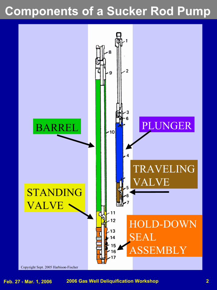
Components of a Sucker Rod Pump
PLUNGERBARREL
TRAVELINGVALVE
STANDINGVALVE
HOLD-DOWNSEAL ASSEMBLY
Copyright Sept. 2005 Harbison-Fischer-

Feb. 27 - Mar. 1, 2006 2006 Gas Well Deliquification Workshop 3
Bottom Hold-Down Sucker Rod Pump
Feb. 27 - Mar. 1, 2006 2006 Gas Well Deliquification Workshop 4
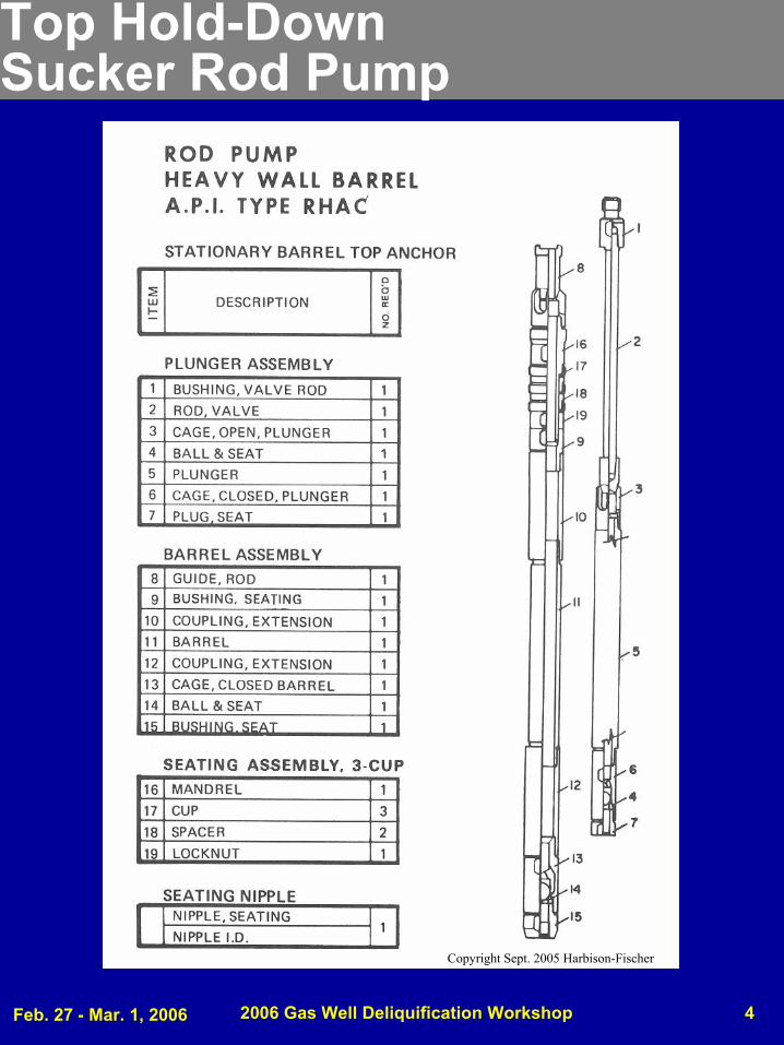
Top Hold-Down Sucker Rod Pump
Copyright Sept. 2005 Harbison-Fischer
Feb. 27 - Mar. 1, 2006 2006 Gas Well Deliquification Workshop 5
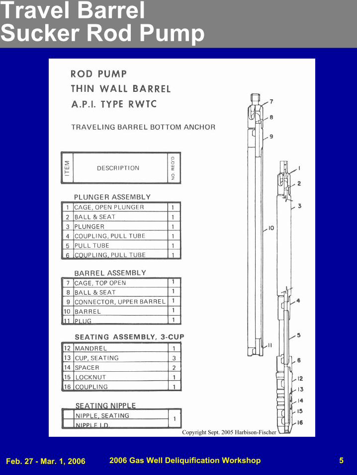
Travel Barrel Sucker Rod Pump
Copyright Sept. 2005 Harbison-Fischer
Feb. 27 - Mar. 1, 2006 2006 Gas Well Deliquification Workshop 6
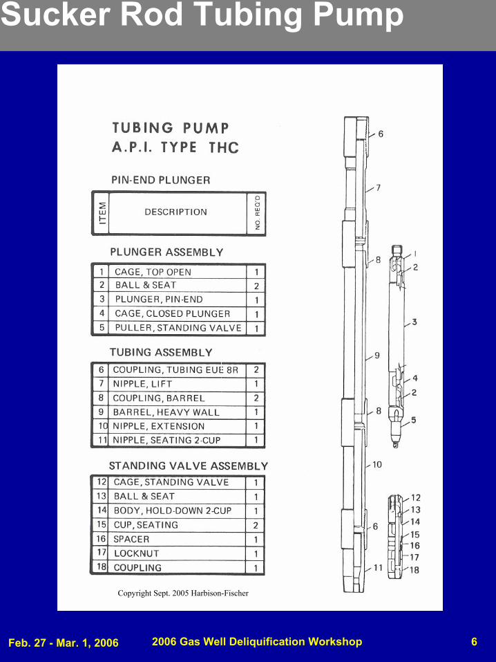
Sucker Rod Tubing Pump
Copyright Sept. 2005 Harbison-Fischer
Feb. 27 - Mar. 1, 2006 2006 Gas Well Deliquification Workshop 7
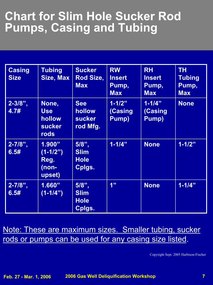
1-1/4”None1”5/8”, Slim Hole Cplgs.
1.660”(1-1/4”)
2-7/8”, 6.5#
1-1/2”None1-1/4”5/8”, Slim Hole Cplgs.
1.900”(1-1/2”) Reg. (non-upset)
2-7/8”, 6.5#
None1-1/4”(Casing Pump)
1-1/2”(Casing Pump)
See hollow sucker rod Mfg.
None, Use hollow sucker rods
2-3/8”, 4.7#
TH Tubing Pump, Max
RH Insert Pump, Max
RW Insert Pump, Max
Sucker Rod Size, Max
Tubing Size, Max
Casing Size
Chart for Slim Hole Sucker Rod Pumps, Casing and Tubing
Note: These are maximum sizes. Smaller tubing, sucker rods or pumps can be used for any casing size listed.
Copyright Sept. 2005 Harbison-Fischer
Feb. 27 - Mar. 1, 2006 2006 Gas Well Deliquification Workshop 8
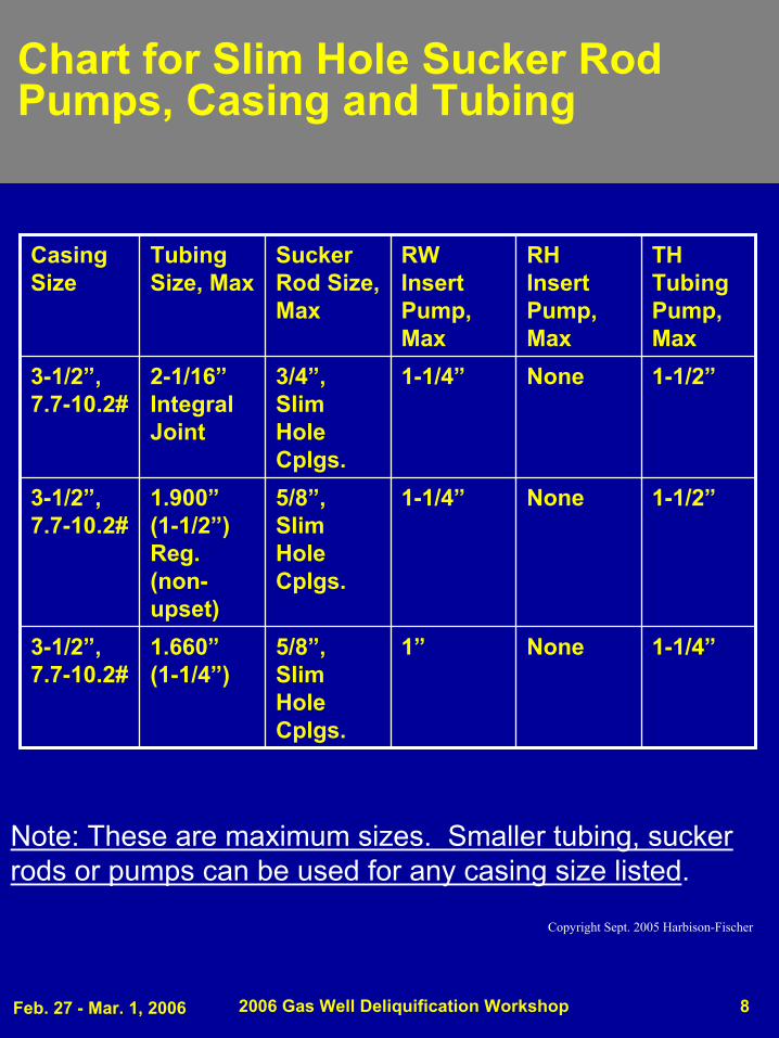
1-1/2”None1-1/4”5/8”, Slim Hole Cplgs.
1.900”(1-1/2”) Reg. (non-upset)
3-1/2”, 7.7-10.2#
1-1/4”None1”5/8”, Slim Hole Cplgs.
1.660”(1-1/4”)
3-1/2”, 7.7-10.2#
1-1/2”None1-1/4”3/4”, Slim Hole Cplgs.
2-1/16”Integral Joint
3-1/2”, 7.7-10.2#
TH Tubing Pump, Max
RH Insert Pump, Max
RW Insert Pump, Max
Sucker Rod Size, Max
Tubing Size, Max
Casing Size
Chart for Slim Hole Sucker Rod Pumps, Casing and Tubing
Note: These are maximum sizes. Smaller tubing, sucker rods or pumps can be used for any casing size listed.
Copyright Sept. 2005 Harbison-Fischer
Feb. 27 - Mar. 1, 2006 2006 Gas Well Deliquification Workshop 9
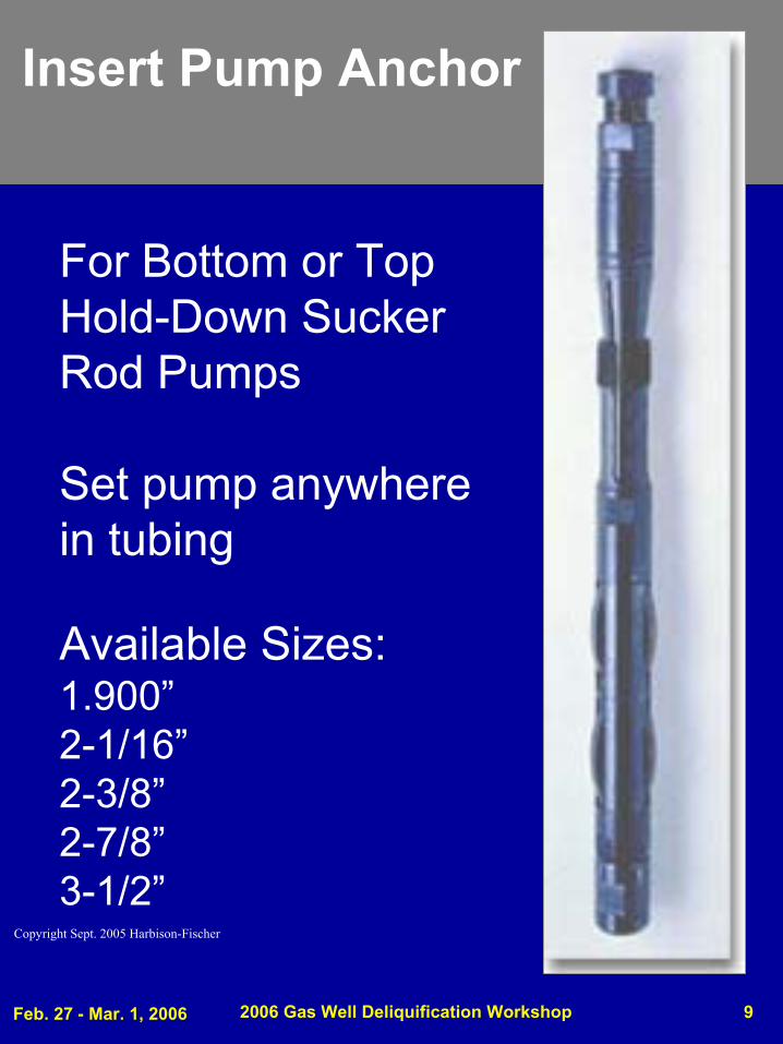
Insert Pump Anchor
For Bottom or Top Hold-Down Sucker Rod Pumps
Set pump anywhere in tubing
Available Sizes:1.900”2-1/16”2-3/8”2-7/8”3-1/2”
Copyright Sept. 2005 Harbison-Fischer
Feb. 27 - Mar. 1, 2006 2006 Gas Well Deliquification Workshop 10
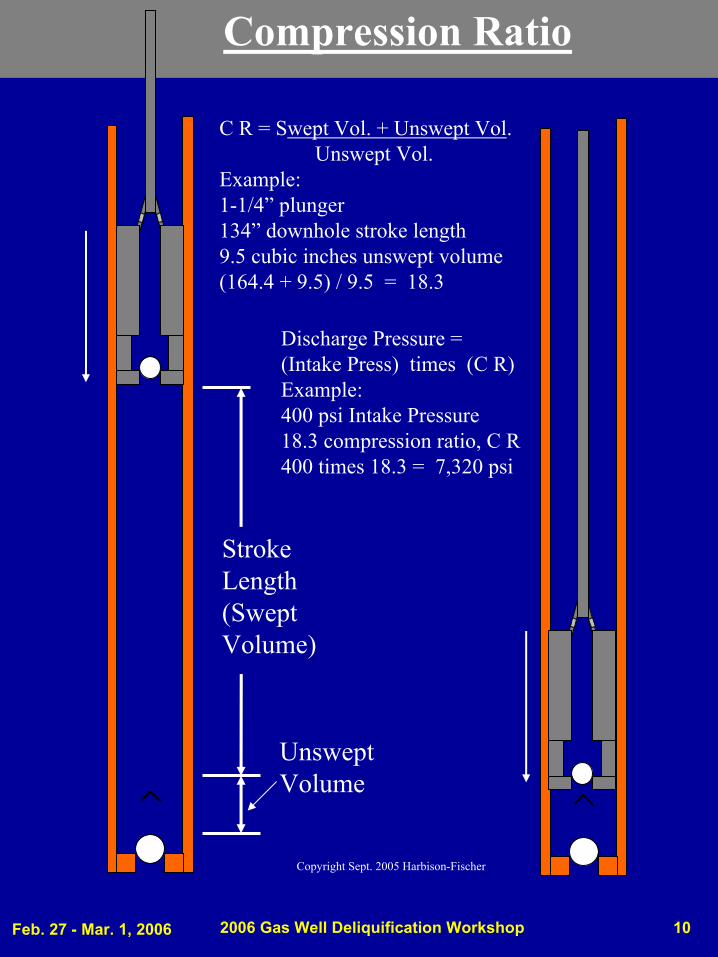
UnsweptVolume
StrokeLength(SweptVolume)
Compression Ratio
C R = Swept Vol. + Unswept Vol.Unswept Vol.
Example: 1-1/4” plunger134” downhole stroke length9.5 cubic inches unswept volume(164.4 + 9.5) / 9.5 = 18.3
Discharge Pressure = (Intake Press) times (C R)Example: 400 psi Intake Pressure18.3 compression ratio, C R400 times 18.3 = 7,320 psi
Copyright Sept. 2005 Harbison-Fischer
Feb. 27 - Mar. 1, 2006 2006 Gas Well Deliquification Workshop 11
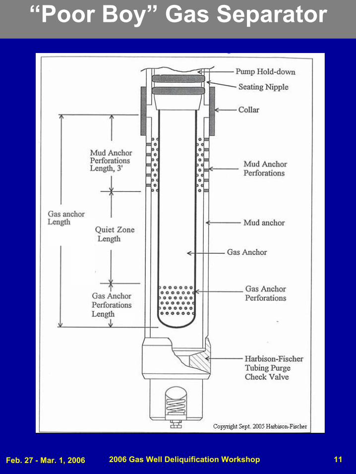
“Poor Boy” Gas Separator
Feb. 27 - Mar. 1, 2006 2006 Gas Well Deliquification Workshop 12
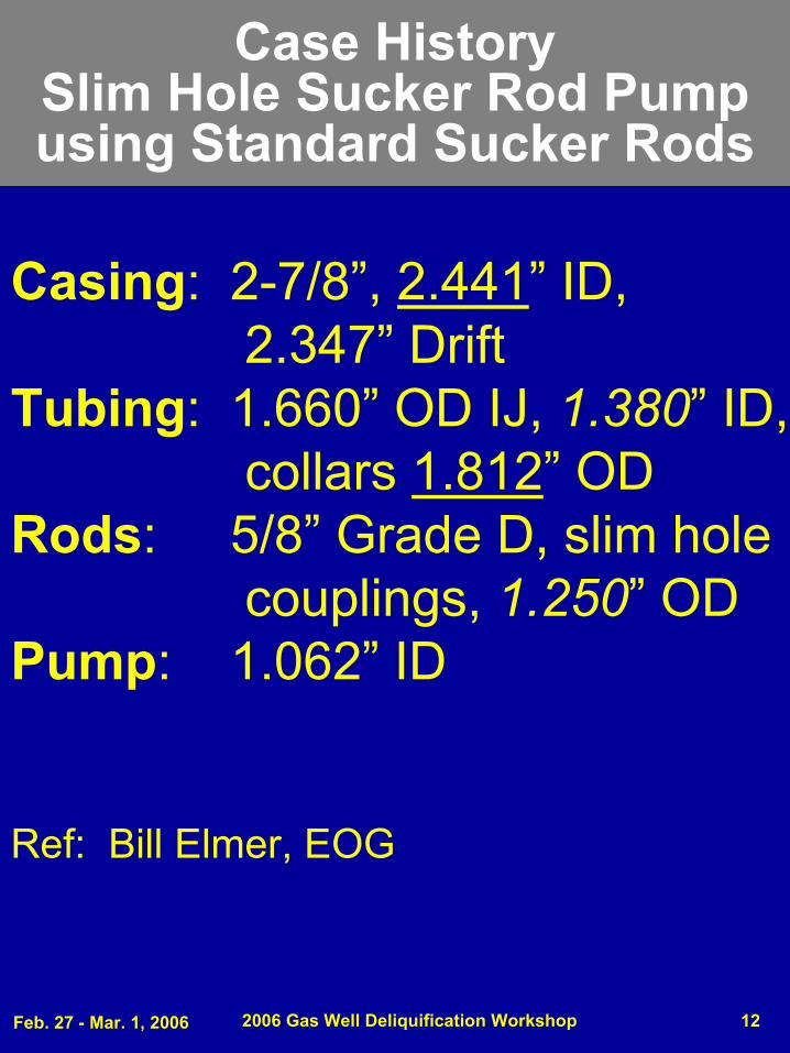
Case HistorySlim Hole Sucker Rod Pump using Standard Sucker Rods
Casing: 2-7/8”, 2.441” ID, 2.347” Drift
Tubing: 1.660” OD IJ, 1.380” ID, collars 1.812” OD
Rods: 5/8” Grade D, slim hole couplings, 1.250” OD
Pump: 1.062” ID
Ref: Bill Elmer, EOG
Feb. 27 - Mar. 1, 2006 2006 Gas Well Deliquification Workshop 13
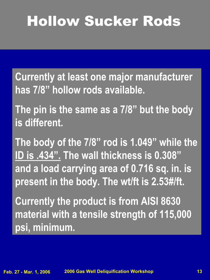
Hollow Sucker Rods
Currently at least one major manufacturer has 7/8” hollow rods available.
The pin is the same as a 7/8” but the body is different.
The body of the 7/8” rod is 1.049” while the ID is .434”. The wall thickness is 0.308”and a load carrying area of 0.716 sq. in. is present in the body. The wt/ft is 2.53#/ft.
Currently the product is from AISI 8630 material with a tensile strength of 115,000 psi, minimum.
Feb. 27 - Mar. 1, 2006 2006 Gas Well Deliquification Workshop 14
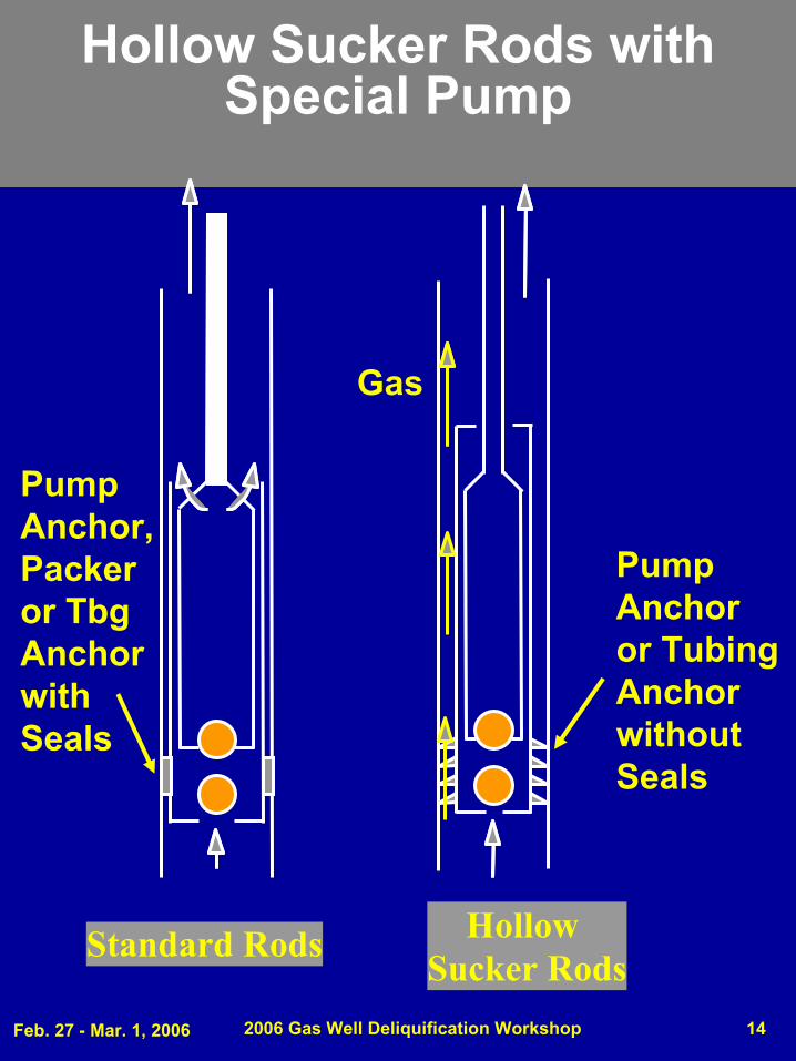
Hollow Sucker Rods with Special Pump
Standard Rods Hollow Sucker Rods
Gas
Pump Anchor, Packer or TbgAnchor with Seals
Pump Anchoror TubingAnchor without Seals
Feb. 27 - Mar. 1, 2006 2006 Gas Well Deliquification Workshop 15
Coiled Tubing as Sucker Rods in Slim Hole
Wells?
SPE paper 56671, is entitled “Coiled Tubing Used as a Continuous-Sucker-Rod System in Slim Holes” .
This paper discusses a method of producing 3 ½ casing wells using coiled tubing as a sucker rod replacement.
Feb. 27 - Mar. 1, 2006 2006 Gas Well Deliquification Workshop 16
Coiled Tubing as Sucker Rods in Slim Hole
Wells?
Maximizing Gas Recovery in Slimhole
Wellbores Utilizing a Coiled Tubing Pumping System (CTPS)
Michael Waid - Anadarko Petroleum
Humberto Leniek - Coil Tubing Americas
Stephen Rowland - BJ Services
Feb. 27 - Mar. 1, 2006 2006 Gas Well Deliquification Workshop 17
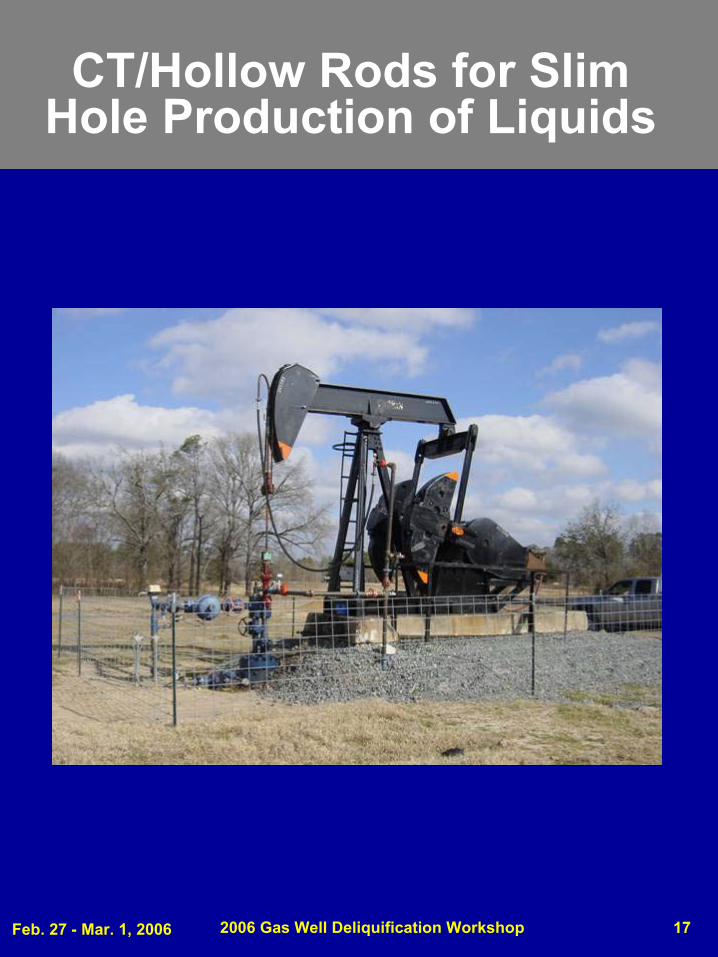
CT/Hollow Rods for Slim Hole Production of Liquids
Feb. 27 - Mar. 1, 2006 2006 Gas Well Deliquification Workshop 18
2006 Gas Well
Deliquification WorkshopDenver, Colorado
Slim Hole PCP’s
Feb. 27 - Mar. 1, 2006 2006 Gas Well Deliquification Workshop 19
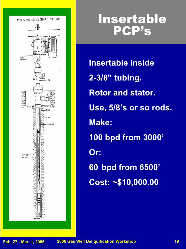
Insertable PCP’s
Insertable inside
2-3/8” tubing.
Rotor and stator.
Use, 5/8’s or so rods.
Make:
100 bpd from 3000’
Or:
60 bpd from 6500’
Cost: ~$10,000.00
Feb. 27 - Mar. 1, 2006 2006 Gas Well Deliquification Workshop 20
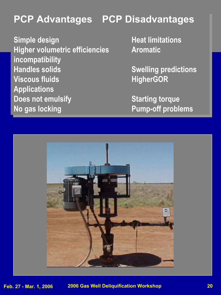
PCP Advantages PCP Disadvantages
Simple design Heat limitationsHigher volumetric efficiencies Aromatic incompatibilityHandles solids Swelling predictionsViscous fluids HigherGORApplicationsDoes not emulsify Starting torqueNo gas locking Pump-off problems
PCP Advantages PCP Disadvantages
Simple design Heat limitationsHigher volumetric efficiencies Aromatic incompatibilityHandles solids Swelling predictionsViscous fluids HigherGORApplicationsDoes not emulsify Starting torqueNo gas locking Pump-off problems
Feb. 27 - Mar. 1, 2006 2006 Gas Well Deliquification Workshop 21
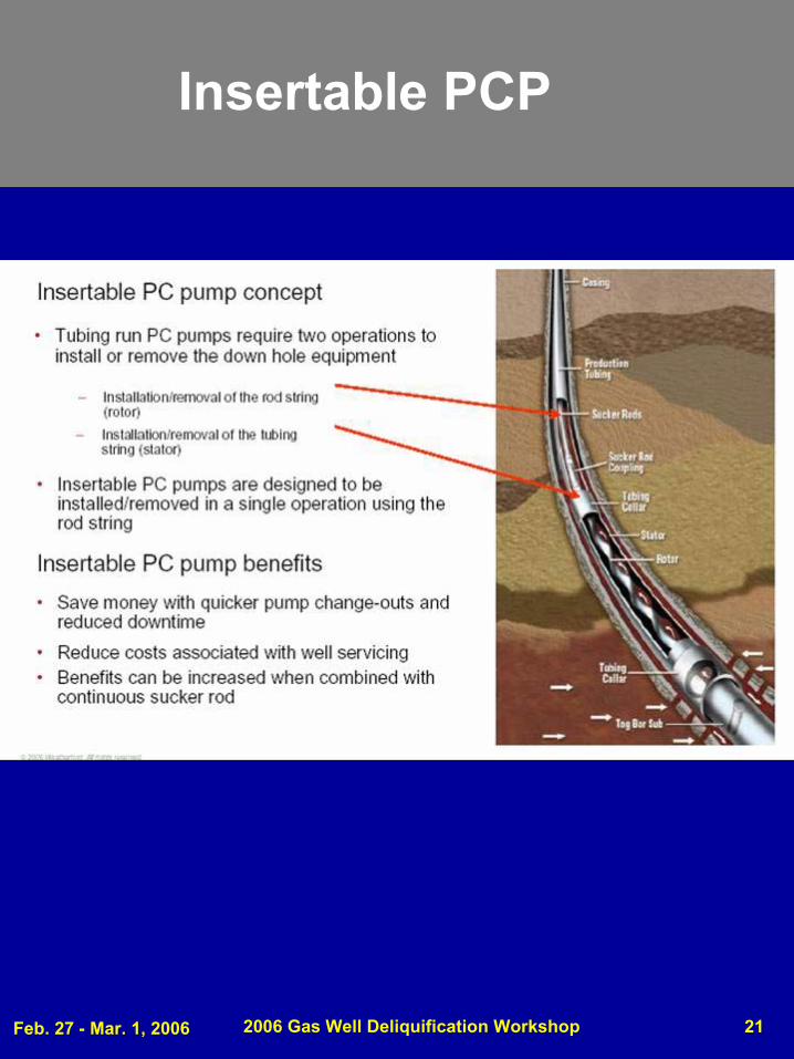
Insertable PCP
Feb. 27 - Mar. 1, 2006 2006 Gas Well Deliquification Workshop 22
Reference for Slim PCP’sReference for Slim PCP’s
SWPSC: 2001
TUBINGLESS PCP APPLICATIONS FOR SLIMHOLE WELLS
BY
NORMAN HEIN, RICK IIMBURY & JAMES BRIEDEN, CONOCO INC, AND RICK ADIAR, PARADIGM LIFT TECHNOLOGIES, LLC.
Feb. 27 - Mar. 1, 2006 2006 Gas Well Deliquification Workshop 23
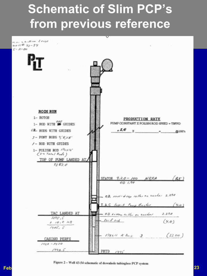
Schematic of Slim PCP’s from previous reference
Feb. 27 - Mar. 1, 2006 2006 Gas Well Deliquification Workshop 24
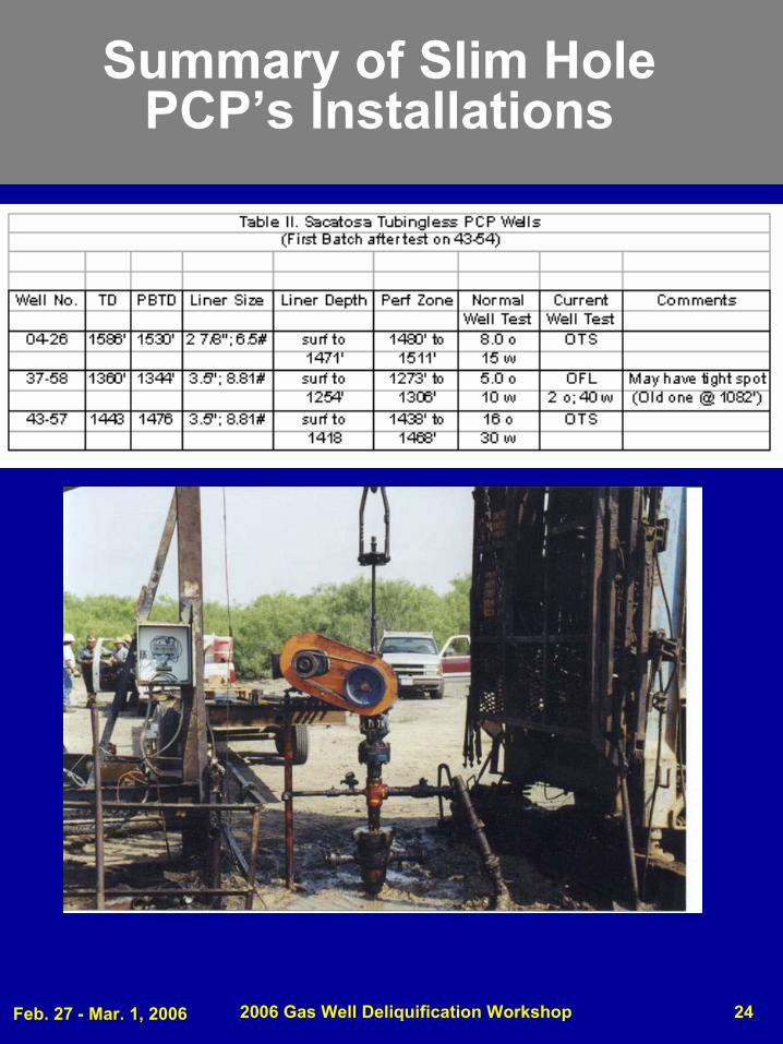
Summary of Slim Hole PCP’s Installations
Feb. 27 - Mar. 1, 2006 2006 Gas Well Deliquification Workshop 25
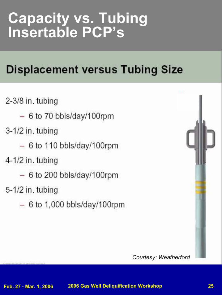
Capacity vs. Tubing Insertable PCP’s
Courtesy: Weatherford
Feb. 27 - Mar. 1, 2006 2006 Gas Well Deliquification Workshop 26
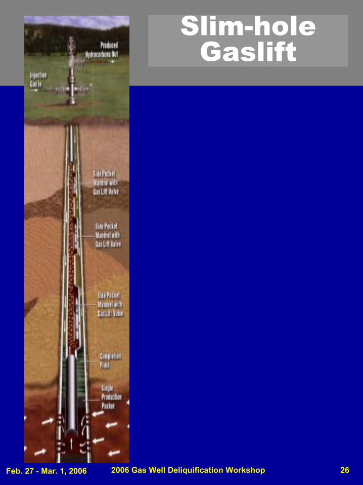
Slim-hole Gaslift

Feb. 27 - Mar. 1, 2006 2006 Gas Well Deliquification Workshop 27
Gaslift Advantages l
Lift gas present?
Handle high rates
Flexible to intermittent
Unobtrusive
Easy to diagnose
Gassy wells good
Crooked holes OK
Corrosion not too bad
Disadvantages
Handle solids
Not efficient
Viscosity is problem
Freezing hydrates can be problem
High producing formation pressure
Pressure on Casing
Feb. 27 - Mar. 1, 2006 2006 Gas Well Deliquification Workshop 28
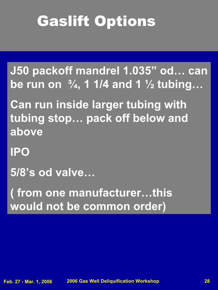
Gaslift Options
J50 packoff mandrel 1.035” od… can be run on ¾, 1 1/4 and 1 ½ tubing…
Can run inside larger tubing with tubing stop… pack off below and above
IPO
5/8’s od valve…
( from one manufacturer…this would not be common order)
Feb. 27 - Mar. 1, 2006 2006 Gas Well Deliquification Workshop 29
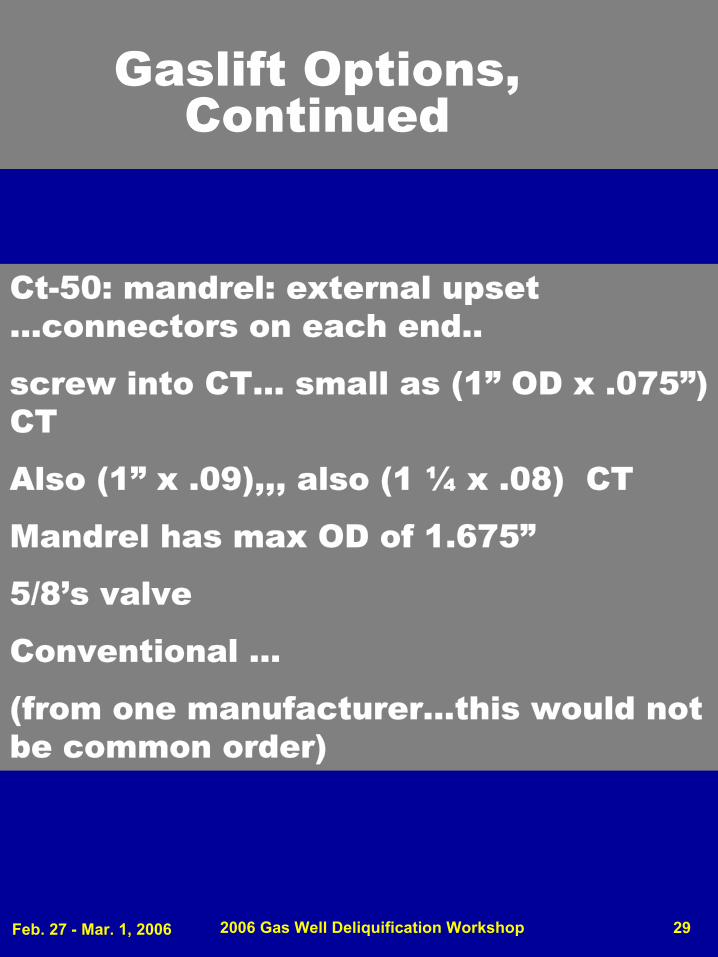
Gaslift Options, Continued
Ct-50: mandrel: external upset …connectors on each end..
screw into CT… small as (1” OD x .075”) CT
Also (1” x .09),,, also (1 ¼ x .08) CT
Mandrel has max OD of 1.675”
5/8’s valve
Conventional …
(from one manufacturer…this would not be common order)
Feb. 27 - Mar. 1, 2006 2006 Gas Well Deliquification Workshop 30
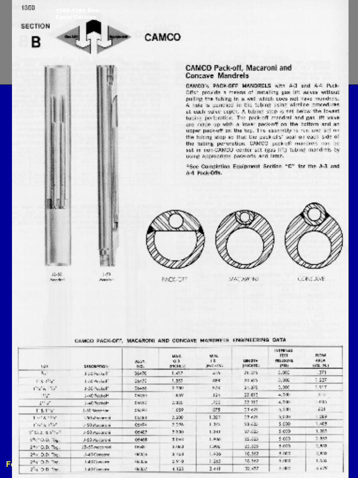
1980-1981 Gen Equip Catalog
Feb. 27 - Mar. 1, 2006 2006 Gas Well Deliquification Workshop 31
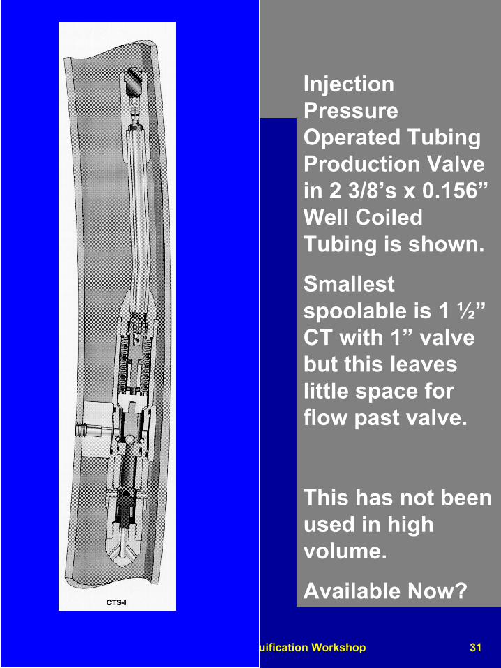
Injection Pressure Operated Tubing Production Valve in 2 3/8’s x 0.156”Well Coiled Tubing is shown.
Smallest spoolable is 1 ½”CT with 1” valve but this leaves little space for flow past valve.
This has not been used in high volume.
Available Now?
Feb. 27 - Mar. 1, 2006 2006 Gas Well Deliquification Workshop 32
2006 Gas Well
Deliquification WorkshopDenver, Colorado
Slim Hole Hydraulic Pump
Feb. 27 - Mar. 1, 2006 2006 Gas Well Deliquification Workshop 33
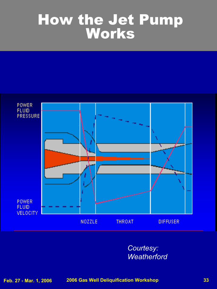
How the Jet Pump Works
Courtesy: Weatherford
Feb. 27 - Mar. 1, 2006 2006 Gas Well Deliquification Workshop 34
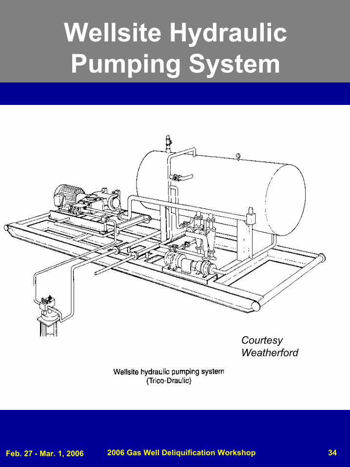
Wellsite Hydraulic Pumping System
Courtesy Weatherford
Feb. 27 - Mar. 1, 2006 2006 Gas Well Deliquification Workshop 35
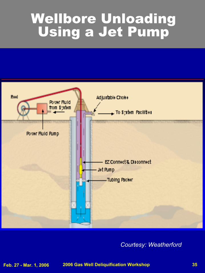
Wellbore Unloading Using a Jet Pump
Courtesy: Weatherford

Feb. 27 - Mar. 1, 2006 2006 Gas Well Deliquification Workshop 36
Feb. 27 - Mar. 1, 2006 2006 Gas Well Deliquification Workshop 37
Feb. 27 - Mar. 1, 2006 2006 Gas Well Deliquification Workshop 38
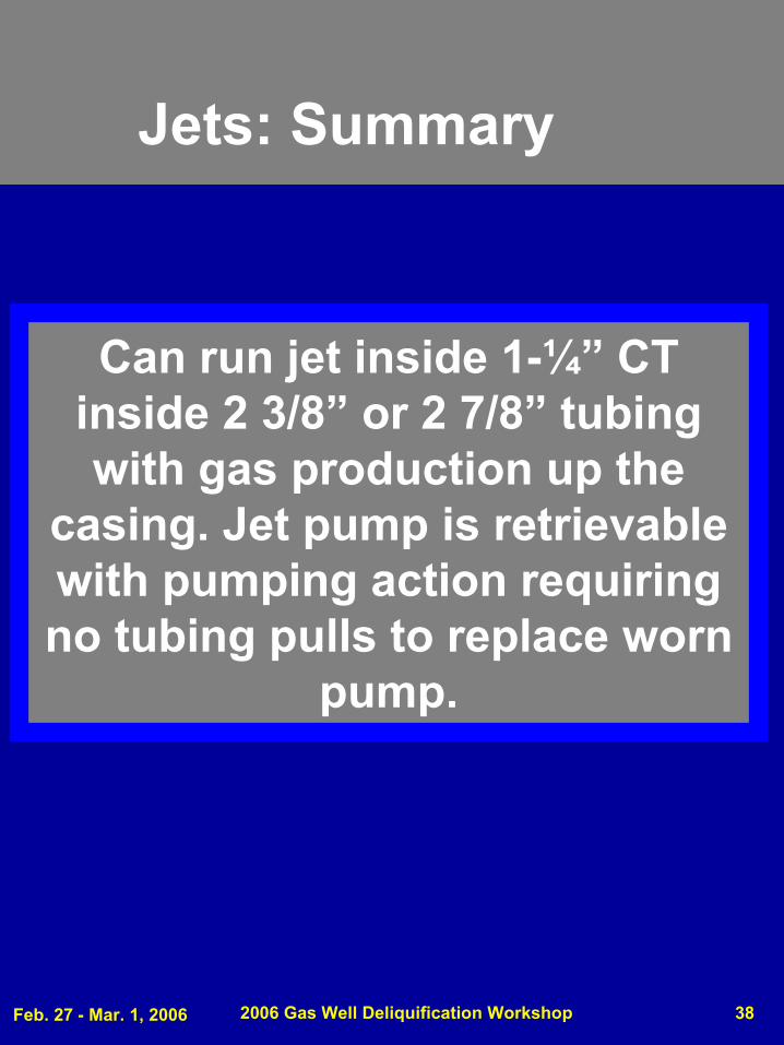
Jets: Summary
Can run jet inside 1-¼” CT inside 2 3/8” or 2 7/8” tubing with gas production up the
casing. Jet pump is retrievable with pumping action requiring no tubing pulls to replace worn
pump.
Feb. 27 - Mar. 1, 2006 2006 Gas Well Deliquification Workshop 39
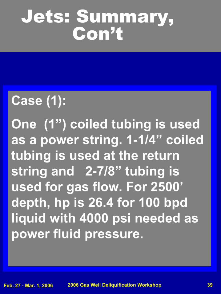
Jets: Summary, Con’t
Case (1):
One (1”) coiled tubing is used as a power string. 1-1/4” coiled tubing is used at the return string and 2-7/8” tubing is used for gas flow. For 2500’depth, hp is 26.4 for 100 bpd liquid with 4000 psi needed as power fluid pressure.
Feb. 27 - Mar. 1, 2006 2006 Gas Well Deliquification Workshop 40
Jets: Summary, Cont’d
Case (2):
1-1/4” coiled tubing is used for the power fluid string. 1” coiled tubing is used as the return string and 2 7/8” tubing is for the gas flow. The hp required is 13.9 at 2600 psi power fluid for 100 bpd total fluids production. The depth is 2500’. This is a “free pump” installation.
Feb. 27 - Mar. 1, 2006 2006 Gas Well Deliquification Workshop 41
2006 Gas Well
Deliquification WorkshopDenver, Colorado
Slim Hole Plunger Lift
Feb. 27 - Mar. 1, 2006 2006 Gas Well Deliquification Workshop 42
Reference for Slim Hole Plunger Lift
3.5” SLIMHOLE PLUNGER LIFT SYSTEM USED IN THE WAMSUTTER DEVELOPMENT ASSET IN GREATER GREEN RIVER BASIN, WYOMING
BY
GRUCE GERRAD, BP, AND BILL HEARN, WEATHERFORD ALS
SOUTHWESTERN PETROLEUM SHORT COURSE - 2003
Feb. 27 - Mar. 1, 2006 2006 Gas Well Deliquification Workshop 43
Plungers in 3 ½ Casing
Conclusions:
The 3-½” slimhole plunger has been successful, with two of the 40+ installations being removed for being unable to flow back against line pressure. The 3 ½”plunger is far less restricive and lifts more than 1 ¼” CT and 2 1/16” tubing. It is cheaper to install over 2 1/16” tubing.
From preceding reference by Gerrad and Hearn:
Feb. 27 - Mar. 1, 2006 2006 Gas Well Deliquification Workshop 44
Summary:
For sim hole artificial lift, some options exist, but depth and
rate options are reduced considerably.
If gas separation is desired, options are reduced even
further.
Plans must be made for what expected rates may be or
drilling slim holes will severely reduce the possible production
rates.
Feb. 27 - Mar. 1, 2006 2006 Gas Well Deliquification Workshop 45
General Reference on Slim Hole Artificial Lift
ARTICIAL LIFT FOR SLIM HOLES, SPE 63042, BY J, LEA, P, ADISOEMARTA, TTU, AND H. V. NICKENS, BP
The paper was prepared for presentation at the 2000 SPE Annual Technical Conference and Exhibition held in Dalls, Texas, 1-4 October 2000
Feb. 27 - Mar. 1, 2006 2006 Gas Well Deliquification Workshop 46
2006 Gas Well
Deliquification WorkshopDenver, Colorado
Slim Hole Artificial Lift
Benny J. WilliamsHarbison-Fischer
J. F. Lea PLTech LLC
QUESTIONS?