Sliding Mode Control of I.M
13
IJCCCE, VOL.7, NO.1, 2007 *AL-Nahrain University / College of Engineering Department of Computer Engineering ROBUST SLIDING MODE CONTROL BASED ON IFOC INDUCTION MACHINE WITH SPEED ESTIMATOR Dr. Noaman M. Noaman * Received on: 16 / 2 /2006 Accepted on: 16 / 1/2007 Abstract In this paper, an indirect field-oriented control (IFOC) induction machine drive with a conventional PI and sliding mode controllers is presented. The robustness of ac machine drive speed performance with these controllers is checked in terms of variation of machine parameters. The design includes rotor speed estimation from measured stator terminal voltages and currents. The estimated speed is used as feedback in an indirect vector control system, such that the speed control is performed without the use of shaft mounted transducers. The high performance of the proposed control schemes under load disturbances is studied via simulation cases. The components of the speed controlled indirect field- oriented induction machine with the both controllers are simulated using SIMULINK, while the dynamic of induction machine is simulated using the potential of S-function block and i ts at tached script fil e. ﺔ ﺻ ﻼ ﺮ ﺷ ﺎ ﺒ ﻣ ﺮ ﯿ ﻐ ﻟ ا ل ﺎ ﺠ ﻤ ﻟ ا ﮫ ﯿ ﺟ ﻮ ﺗ ة ﺮ ﻄ ﯿ ﺳ و ذ ة ر ﺪ ﻘ ﻟ ا ق ﻮ ﺴ ﻣ ﺔ ﻋ ﺮ ﺳ ﻰ ﻠ ﻋ ة ﺮ ﻄ ﯿ ﺳ ﻲ ﺘ ﻘ ﯾ ﺮ ﻃ ضﺮ ﻋ ﺗ ﺚ ﺤ ﺒ ﻟ ا اﺬ ھ ﻲ ﻓ(IFOC Drive) ﻲ ﻠ ﻣ ﺎ ﻜ ﺗ ﻲ ﺒ ﺎ ﻨ ﺗ ﺮ ﯿ ﻣﺴ م ا ﺪ ﺨ ﺘ ﺳ ا ﺎ ﻤ وھ ) PI Controller ( ﯿﻄﺮ ﻣﺴ ﻖ ﻟ ﺰ ﻨ ﻤ ﻟ ا ﻂﻤ ﻨ ﻟ ا(Sliding Mode Controller) . ﺔﻋ ﺮ اﻟﺴ ﺔ ﻤ ﯿ ﻗ ﻰ ﻠ ﻋ ﺔ ﻈ ﻓ ﺎ ﺤ ﻤ ﻠ ﻟ بو ﺎ ﻨ ﺘ ﻤ ﻟ ا ر ﺎ ﯿ ﺘ ﻟ ا و ذ ر ﺪ ﻘ اﻟ ق ﻮ ﺴ ﻣ ﺔ ﯿ ﻠ ﺑ ﺎ ﻗ ر ﺎ ﺒ ﺘ ﺧ ا ﻢ ﺗﺔ ﻨ ﻛ ﺎ ﻤ ﻟ ا ت ﺎ ﻤ ﻠ ﻌ ﻣ ﻲ ﻓ ﺮ ﯿ ﻐ ﺗ ث ا ﺪ ﺣ إ ل ﺧﻼ ﻦ ﻣ ﻚ ﻟ ذ و ﺔ ﺣ ﺮ ﺘ ﻘ ﻤ ﻟ ا ت ﺮ ﻄ ﯿ ﺴ ﻤ ﻟ ا ﻠﻚ ﺗ د ﻮ ﺟ ﻮ ﺑ . ﻊ ﻣ ﻂ ﺑ ﺮ ﺗ ﺔ ﯾ د ﺎ ﻣ ة ﺰ ﮭ ﺟ م ا ﺪ ﺨ ﺘ ﺳ ا ﻰﻟ إ ﺔ ﺟ ﺎ ﺤ ﻟ ا ن و ﺪ ﺑ ﺔ ﻋ ﺮ ﺴ ﻟ ا ﺔ ﻤ ﯿ ﻗ ﻦ ﯿ ﻤ ﺨ ﺗ ﺚ ﺤ ﺒ ﻟ ا ﻦ ﻤ ﻀ ﺗ ﻚ ﻟ ﺬ ﻛ ك ﺮ ﺤ ﻤ ﻟ ا ﺗ و ﺎ ﮭ ﻟ ا ﺪ ﺒ ﺘ ﺳ ا ﻣ ﺎ ﻧ ﺮ ﺒ ﺑ ﻞ ﻤ ﻌ ﯾ ﻠ ﻋﺒ ﻗ ا ﺮ ﻣ ﻋ ﺮ ﺴ ﻟ ا ﮭ ﻨ ﯿ ﻤ ﺨ ﺗ و ) Speed Estimator ( س ﺎ ﯿ ﻗ ل ﻼ ﺧ ﻦ ﻣ ﻚ ﻟذ وﺔ ﻨ ﻛ ﺎ ﻤ ﻠ ﻟ ﺔ ﯿ ﻓ ﺮ ﻄ ﻟ ا ت ﺎ ﯿ ﺘ ﻟ ﻮ ﻔ ﻟ ا و ت ا ر ﺎ ﯿ ﺘ ﻟ ا ﻢ ﯿ ﻗ. ﺔ ﺣ ﺮ ﺘ ﻘ ﻤ ﻟ ا ت ا ﺮ ﻄ ﯿ ﺴ ﻤ ﻟ ا د ﻮ ﺟﻮ ﺑ ة ر ﺪ ﻟﻘ ا ق ﻮ ﻟﻤﺴ ﺔ ﻘ ﻠ ﻐ ﻤ ﻟ ا ﺔ ﻣ ﻮ ﻈ ﻨ ﻤ ﻟ ا ت ﺎ ﻧ ﻮ ﻜ ﻣ ﻞ ﯿ ﺜ ﻤ ﺗ ﻢ ﺗ ﻦ ﻤ ﺨ ﻣ و ﺔ ﻋ ﺮ ﺴﻟ اﺞ ﻣ ﺎ ﻧ ﺮ ﺑ م ا ﺪ ﺨ ﺘ ﺳ ﺎ ﺑ ) Simulink ( ﻤ ﻨ ﯿ ﺑ ﺗ د ﺎ ﻔ ﺘ ﺳ ﻻ ا ﻦ ﻣ ﺔ ﯿ ﻠ ﺑ ﺎ ﻗ ﺔ ﻠﺘ ﻛ ) S-Function Block ( ض ﺮ ﻟﻐ ة ﺪ ﻣ ﺎ ﻌ ﺘ ﻤ ﻟ ا ر و ﺎ ﺤ ﻤ ﻟ ا ﻲ ﻓ ﺔ ﻨ ﻛ ﺎ ﻤ ﻟ ا ج ذ ﻮ ﻤ ﻧ ا ﻞ ﯿ ﺜ ﻤ ﺗ ) qd-Frame .(
-
Upload
nagulapati-kiran -
Category
Documents
-
view
232 -
download
0
Transcript of Sliding Mode Control of I.M

8/12/2019 Sliding Mode Control of I.M
http://slidepdf.com/reader/full/sliding-mode-control-of-im 1/12
IJCCCE, VOL.7, NO.1, 2007
*AL-Nahrain University / College of Engineering Department of Computer Engineering
ROBUST SLIDING MODE CONTROL BASED ON IFOC
INDUCTION MACHINE WITH SPEED ESTIMATOR
Dr. Noaman M. Noaman *Received on: 16 / 2 /2006
Accepted on: 16 / 1/2007
Abstract
In this paper, an indirect field-oriented control (IFOC) induction machine drive
with a conventional PI and sliding mode controllers is presented. The robustness of ac
machine drive speed performance with these controllers is checked in terms of variation
of machine parameters.The design includes rotor speed estimation from measured stator terminal
voltages and currents. The estimated speed is used as feedback in an indirect vectorcontrol system, such that the speed control is performed without the use of shaft
mounted transducers.
The high performance of the proposed control schemes under load disturbances
is studied via simulation cases. The components of the speed controlled indirect field-
oriented induction machine with the both controllers are simulated using SIMULINK,
while the dynamic of induction machine is simulated using the potential of S-function
block and its attached script file.
ة ص ال
ر
اش ب م
یر غ ل ا
ال جم ل ا
یھ جو ت
ة ر طی س
ذو
ة رد ق ل ا
وق س م
ة ع ر س
على
ة ر طی س
تي ق ی ر ط
عرض
تم
بحث ل ا
ھذا
في
(IFOC Drive)لي م ا
تك
بي
اس ن ت
طر ی
مس
ام د خت
س ا
ا
ھم و
)PI Controller (طر ی
قمس
ل زن م ل ا
نمط
ال
(Sliding Mode Controller).ة رع
س ال
ة
یم ق
ى
عل
ة
فظ ا حم ل ل
اوب
تن مل ا
ار
تی ل ا
ذو
رة د
الق
وق س م
لیة ب اق
بار ت خا
تم
ة ن ك ا م ل ا
ات م ل ع م
في
یر غ ت
اث د ح إ
الل خ
من
لك ذ و
ترحة ق م ل ا
ات ر طی سم ل ا
ك تل
د و ج و ب
.
مع
بط ر ت
یة د ا م
ة ز ھ ج م ا د خت سا
إلى
اجة حل ا
ون د ب
ة ع ر س ل ا
مة ی ق
ین م خت
بحث ل ا
من ض ت
لك ذ ك
رك
مح ل ا
وت
ھا ل ا د ب ت سا
ام ن رب ب
مل ع ی
بعل ق ا رم
رع س ل ا
نھ ی م خت و
)Speed Estimator (س ا
قی
الل
خ
ن
م
ك
وذل
نة ك ا م ل ل
یة ف ر ط ل ا
یات ت ل و ف ل ا و
ات را ی ت ل ا
یم ق
.
ة
ترح ق م ل ا
ات ر ط ی
مس ل ا
ود
بوج
رة د
الق
وق
لمس
ة
لق غ م ل ا
ة
وم ظن م ل ا
ت ا
ن و ك م
ل
ی ث م ت
م
نت
م خ م و
عة س ر ال
مج ا ن ر ب
ام د خت سا ب
)Simulink (نم ی ب
ت
د ا ف ت سال ا
ن
م
ة
لی ب اق
ة
كتل
)S-Function Block ( رض
لغ
ة د م ا ع ت م ل ا
ور ا حم ل ا
في
نة ك ا م ل ا
ذج و م ن ا
یل ث م ت
)qd-Frame.(

8/12/2019 Sliding Mode Control of I.M
http://slidepdf.com/reader/full/sliding-mode-control-of-im 2/12
IJCCCE, VOL.7, NO.1, 2007 Robust Sliding Mode Control Based on IFOCInduction Machine with Speed Estimator
1. Introduction
Field orientation control (FOC)or vector control of induction machine
achieves decoupled torque and fluxdynamics leading to independent
control of the torque and flux as for a
separately excited DC motor [1]. This is
achieved by orthogonal projection of
the stator current into a torque-
producing component and flux- producing component. This technique is
performed by two basic methods: directand indirect vector control. With direct
field orientation, the instantaneous
value of the flux is required and
obtained by direct measurement using
flux sensors or flux estimators, whereas
indirect field orientation is based on the
inverse flux model dynamics, and there
are three possible implementation basedon the stator, rotor, or air gap flux
orientation. The rotor flux indirect
vector control technique is the mostwidely used due to its simplicity [2].
FOC methods are attractive but sufferfrom one major disadvantage. They are
sensitive to parameter variations such as
rotor time constant and incorrect flux
measurement or estimation at low
speeds. Consequently, performance
deteriorates and a conventional
controller such as a PI is unable to
maintain satisfactory performance underthese conditions [1].
A sliding mode control (SMC) is
basically an adaptive control schemethat gives robust performance of a drive
with parameter variations. The control
is nonlinear and applied to linear and
nonlinear plant. In SMC, the drive
response is forced to slide along a
predefined trajectory in a phase plane
by a switching control algorithm,irrespective drive's parameter variation
and load disturbance [3, 4].Controlled induction motor
drives without mechanical speed
sensors at the motor shaft have theattractions of low cost and high
reliability. To replace the sensor, theinformation on the rotor speed is
extracted from measured stator voltages
and currents at the motor terminals.
Vector-controlled drives require
estimating the magnitude and spatial
orientation of the fundamental magneticflux waves in the stator or in the rotor
[4, 5].In this paper, two control
strategies are considered to adjust the
speed of the drive system: PI and
sliding mode controller. The robustness
of these suggested controllers are
checked in terms of motor parameter
variations. The speed controller is
performed under no mechanical speedsensors and speed observer, based on
the software program, is adopted for
this purpose.
2.Dynamic Model of Induction
Machine
Induction machine (IM)
equations in arbitrary rotating reference
frame can be represented in stator and
rotor dq voltage equations [5-8]:
qs sqsdsds
qs sdsqsqs
ir pv
ir pv
qr r qr r dr dr
qr r dr r qr qr
ir pv
ir pv
)(
)(
(1)
Where v is voltage; is the flux
linkage; i is the current; is the
arbitrary speed of the reference frame;
r is the resistance and p is the time
derivative. The subscript r and s denotes
the rotor and stator values respectivelyreferred to the stator, and the subscripts
8/12/2019 Sliding Mode Control of I.M
http://slidepdf.com/reader/full/sliding-mode-control-of-im 3/12
IJCCCE, VOL.7, NO.1, 2007 Robust Sliding Mode Control Based on IFOCInduction Machine with Speed Estimator
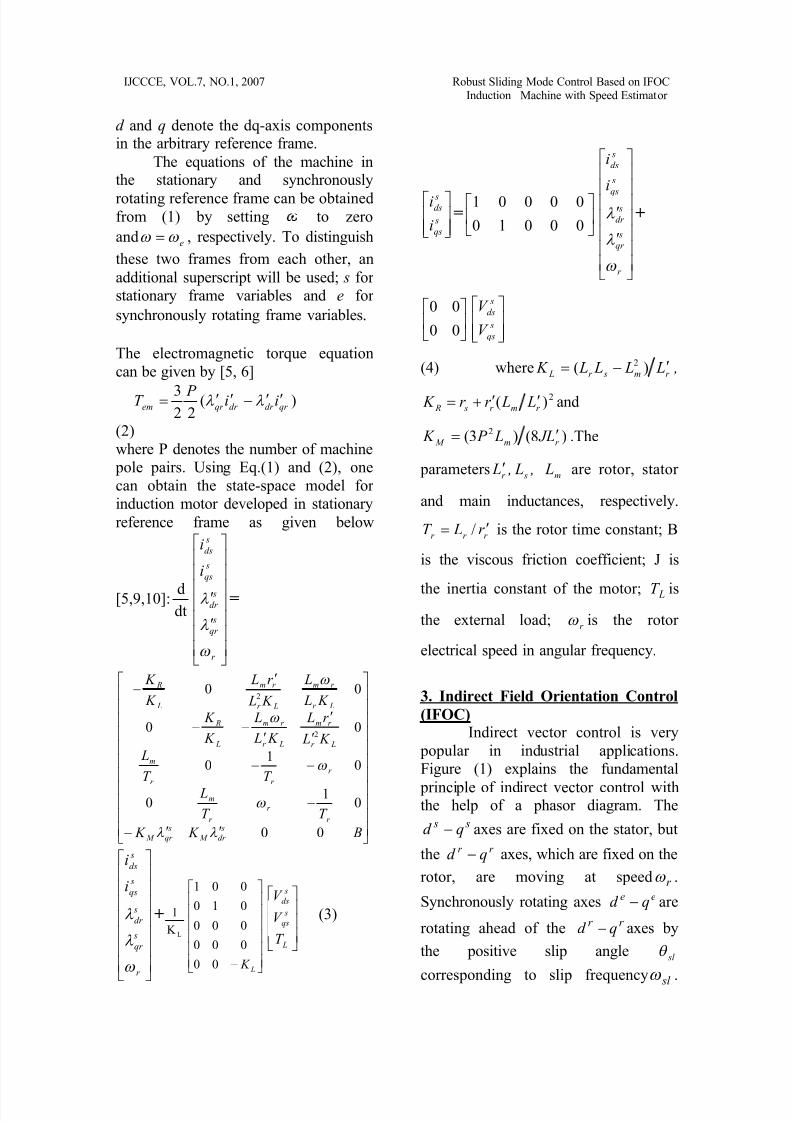
d and q denote the dq-axis componentsin the arbitrary reference frame.
The equations of the machine inthe stationary and synchronously
rotating reference frame can be obtainedfrom (1) by setting to zero
and e , respectively. To distinguish
these two frames from each other, an
additional superscript will be used; s for
stationary frame variables and e for
synchronously rotating frame variables.
The electromagnetic torque equation
can be given by [5, 6]
)(22
3qr dr dr qr em ii P T
(2)
where P denotes the number of machine
pole pairs. Using Eq.(1) and (2), one
can obtain the state-space model for
induction motor developed in stationary
reference frame as given below
[5,9,10]:dtd
r
s
qr
s
dr
s
qs
s
ds
i
i
=
B K K
T T
L
T T
L
K L
r L
K L
L
K
K
K L
L
K L
r L
K
K
s
dr M
s
qr M
r
r
r
m
r
r r
m
Lr
r m
Lr
r m
L
R
Lr
r m
Lr
r m
L
R
00
01
0
01
0
00
00
2
2
r
s
qr
s
dr
s
qs
s
ds
i
i
+LK
1
L
K 00
000
000
010
001
L
s
qs
s
ds
T
V
V
(3)
s
qs
sds
i
i=
00010
00001
r
s
qr
s
dr
s
qs
s
ds
i
i
+
00
00
s
qs
s
ds
V
V
(4) where r m sr L L L L L K )( 2 ,
2)( r mr s R L Lr r K and
)8()3( 2
r m M L J L P K .The
parameters r L , s L , m L are rotor, stator
and main inductances, respectively.
r r r r LT / is the rotor time constant; B
is the viscous friction coefficient; J is
the inertia constant of the motor; LT is
the external load; r is the rotor
electrical speed in angular frequency.
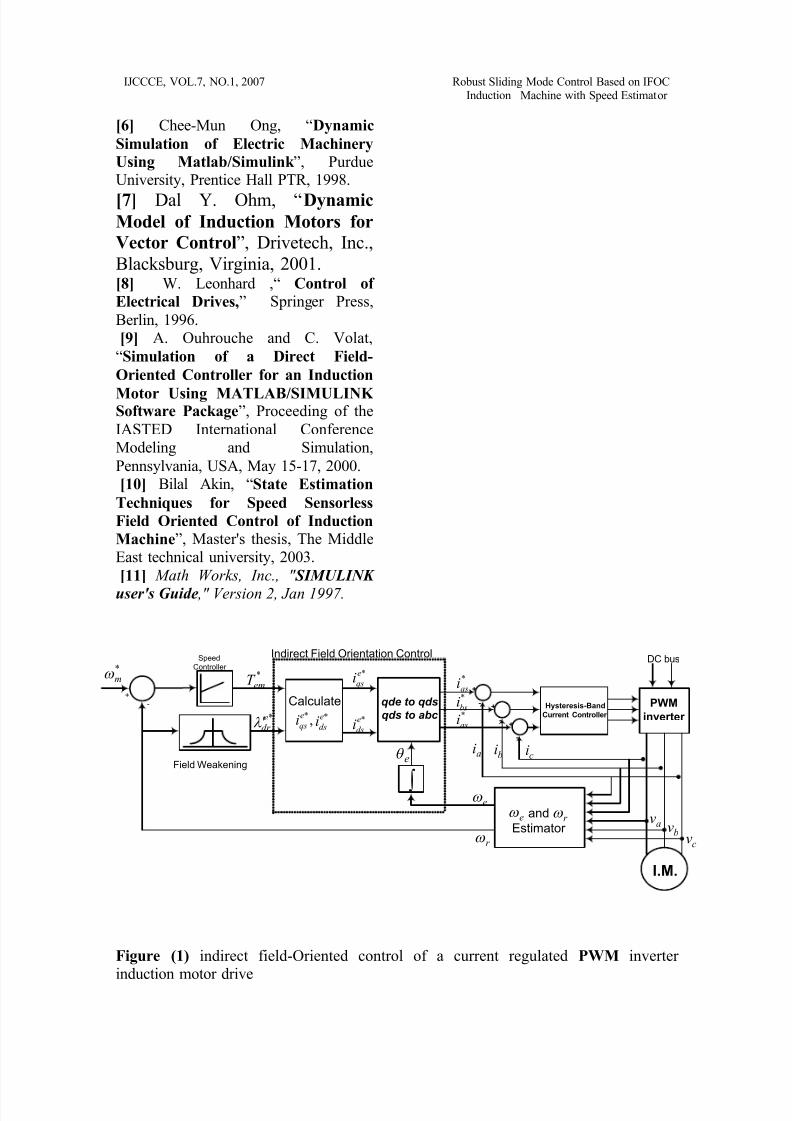
3. Indirect Field Orientation Control
(IFOC)Indirect vector control is very
popular in industrial applications.
Figure (1) explains the fundamental
principle of indirect vector control withthe help of a phasor diagram. The
s s qd axes are fixed on the stator, but
the r r qd axes, which are fixed on the
rotor, are moving at speed r .
Synchronously rotating axes ee qd are
rotating ahead of the r r qd axes by
the positive slip angle sl
corresponding to slip frequency sl .
8/12/2019 Sliding Mode Control of I.M
http://slidepdf.com/reader/full/sliding-mode-control-of-im 4/12
IJCCCE, VOL.7, NO.1, 2007 Robust Sliding Mode Control Based on IFOCInduction Machine with Speed Estimator
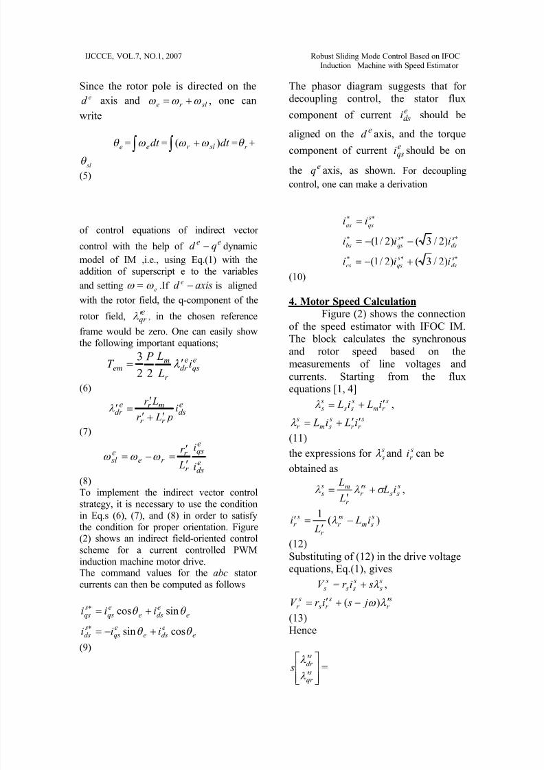
Since the rotor pole is directed on theed axis and sl r e , one can
write
e = dt e = dt sl r )( = r +
sl
(5)
The phasor diagram suggests that fordecoupling control, the stator flux
component of currentedsi should be
aligned on thee
d axis, and the torquecomponent of current e
qsi should be on
the eq axis, as shown. For decoupling
control, one can make a derivation
of control equations of indirect vector
control with the help ofee qd dynamic
model of IM ,i.e., using Eq.(1) with the
addition of superscript e to the variables
and setting e .If axisd e is aligned
with the rotor field, the q-component of the
rotor field,e
qr , in the chosen reference
frame would be zero. One can easily show
the following important equations;
i L
L P T e
qse
dr r
mem
22
3
(6)
i p Lr
Lr eds
r r
mr edr
(7)
i
i
L
r
eds
eqs
r
r r e
e sl
(8)To implement the indirect vector controlstrategy, it is necessary to use the condition
in Eq.s (6), (7), and (8) in order to satisfythe condition for proper orientation. Figure
(2) shows an indirect field-oriented controlscheme for a current controlled PWM
induction machine motor drive.The command values for the abc stator
currents can then be computed as follows
eedse
eqs
sds
eedse
eqs
sqs
iii
iii
cossin
sincos
(9)
s
ds
s
qscs
s
ds
s
qsbs
s
qsas
iii
iii
ii
)2/3()2/1(
)2/3()2/1(
(10)
4. Motor Speed CalculationFigure (2) shows the connection
of the speed estimator with IFOC IM.
The block calculates the synchronous
and rotor speed based on the
measurements of line voltages and
currents. Starting from the fluxequations [1, 4]
sr m
s s s
s s i Li L ,
sr r
s sm
sr i Li L
(11)
the expressions for s s and s
r i can be
obtained as
s s s
sr
r
m s s i L
L
L
,
)(1 s
sm sr
r
sr i L
Li
(12)
Substituting of (12) in the drive voltageequations, Eq.(1), gives
s s
s s s
s s sir V ,
sr
sr s
sr j sir V )(
(13)Hence
sqr
sdr s
=
8/12/2019 Sliding Mode Control of I.M
http://slidepdf.com/reader/full/sliding-mode-control-of-im 5/12
IJCCCE, VOL.7, NO.1, 2007 Robust Sliding Mode Control Based on IFOCInduction Machine with Speed Estimator
sqs
sds
s s
s s
sqs
sds
m
r
i
i
L sr
L sr
V
V
L
L
0
0
(14)
sqr
sdr s
=
sqs
sds
s sr
r
sqs
sds
m
r L sr T
T
i
i L
T
11
(15)
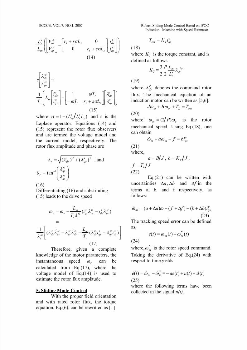
where )(1 2
sr m L L L and s is the
Laplace operator. Equations (14) and(15) represent the rotor flux observers
and are termed the voltage model and
the current model, respectively. Therotor flux amplitude and phase are
22 )()( sqr
sdr r , and
s
dr
s
qr
r
1tan
(16)Differentiating (16) and substituting
(15) leads to the drive speed
)(2
s
qr
s
ds
s
dr
s
qs
r r
mer ii
T
L
=
)((
12
s
ds
s
qr
s
qs
s
dr
r
m s
dr
s
qr
s
qr
s
dr
r
iiT
L
(17)
Therefore, given a complete
knowledge of the motor parameters, the
instantaneous speed r can be
calculated from Eq.(17), where the
voltage model of Eq.(14) is used to
estimate the rotor flux amplitude.
5. Sliding Mode Control
With the proper field orientationand with rated rotor flux, the torque
equation, Eq.(6), can be rewritten as [1]
e
qsT em i K T
(18)
where T K is the torque constant, and is
defined as follows
T K = e
dr
r
m
L
L P *
22
3
(19)
where *dr denotes the command rotor
flux. The mechanical equation of an
induction motor can be written as [5,6]:
em Lmm T T B J
(20)
wherer m
P )2( is the rotor
mechanical speed. Using Eq.(18), one
can obtaine
qsmm bi f a
(21)
where,
J Ba , J K b T ,
J T f L
(22)Eq.(21) can be written with
uncertainties a , b and f in theterms a, b, and f respectively, as
follows:
eqsm ibb f f aa )()()(
(23)
The tracking speed error can be defined
as,
)()()( * t t t e mm
(24)
where, *m is the rotor speed command.
Taking the derivative of Eq.(24) with
respect to time yields:
*)( mmt e = )()()( t d t ut ae
(25)where the following terms have been
collected in the signal u(t),
8/12/2019 Sliding Mode Control of I.M
http://slidepdf.com/reader/full/sliding-mode-control-of-im 6/12
IJCCCE, VOL.7, NO.1, 2007 Robust Sliding Mode Control Based on IFOCInduction Machine with Speed Estimator
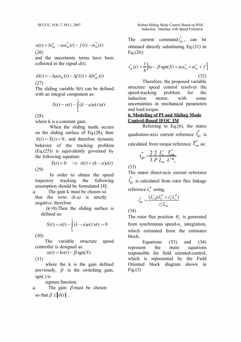
)()()()( ** t t f t abit u mmeqs
(26)
and the uncertainty terms have beencollected in the signal d(t),
)()()()( t bit f t at d eqsm
(27)
The sliding variable S(t) can be definedwith an integral component as:
t
d eak t et S
0
)()()()(
(28)
where k is a constant gain.When the sliding mode occurs
on the sliding surface of Eq.(28), then
0)()( t S t S , and therefore dynamic
behavior of the tracking problem
(Eq.(25)) is equivalently governed by
the following equation:
0)( t S )()()( t eak t e
(29)In order to obtain the speed
trajectory tracking the followingassumption should be formulated [4]:
The gain k must be chosen so
that the term (k-a) is strictly
negative, therefore
(k<0).Then the sliding surface is
defined as:
0)()()()(
0
t
d eak t et S
(30)
The variable structure speedcontroller is designed as:
)sgn()()( S t ket u
(31)where the k is the gain defined
previously, is the switching gain,
sgn(.) is
signum function.
The gain must be chosen
so that )(t d .
The current command *qsi , can be
obtained directly substituting Eq.(31) in
Eq.(26):
f aS keb
t i mmqs *** )sgn(1
)(
(32)
Therefore, the proposed variable
structure speed control resolves the
speed-tracking problem for the
induction motor, with someuncertainties in mechanical parameters
and load torque.
6. Modeling of PI and Sliding Mode
Control-Based IFOC IM Referring to Eq.(6), the stator
quadrature-axis current reference*
qsi is
calculated from torque reference*
emT as:
*qsi =
r
em
m
r T
L
L
P *
2
3
2*
(33)
The stator direct-axis current reference
*qsi is calculated from rotor flux linkage
reference *r using,
mr
r r r r ds
Lr
r p Li
)( ***
(34)
The rotor flux position e is generated
from synchronous speed e integration,
which estimated from the estimator
block.
Equations (33) and (34)
represent the main equations
responsible for field oriented-control,
which is represented by the Field
Oriented block diagram shown inFig.(3)
8/12/2019 Sliding Mode Control of I.M
http://slidepdf.com/reader/full/sliding-mode-control-of-im 7/12
IJCCCE, VOL.7, NO.1, 2007 Robust Sliding Mode Control Based on IFOCInduction Machine with Speed Estimator
The conversion of quantities from dqeto abc reference frames are executed by
dq_abc block,The quantities in abc reference frame
are converted to dqs frame usingFig.(5),
The speed controller with the
proportional-integral type can be
implemented using Simulinks blocks
The modeling of the elements of thesliding mode controller is shown if
Fig.(7)The current regulator, which consists of
three hysteresis controllers, is built with
Simulink blocks. The motor currents are
provided by the multiplexer output of
the induction machine block,
The simulation block diagram for a
three-phase, two-level PWM inverter is
shown below.
Each leg of the inverter is represented
by a "switch" which has three inputterminals and one output terminal. The
output of the switch oscillates between(+0.5 dcV ) and (-0.5 dcV ), which is
characteristic of a pole of an inverter.
coboaoan vvvv )31()31()32(
coaobobn vvvv )31()31()32(
(35)
boaococn vvvv )31()31()2(
The SIMULINK modeling of speed
observer based on Eq.(17) is illustratedin Fig.(10)
Block diagrams of Figs.(3)-(10)
can be assembled to yield the block
diagram of PI or sliding mode
controller-based IFOC I.M. , which is
given in Fig.(11)
7. Simulated ResultsIn this section the speed
regulation performance of the proposedsliding mode is compared to that of the
PI controller of the field orientedcontrol IM. The performance is checked
in terms of load torque variations. The
simulation is performed in SIMULINK,
while the IM model is simulated using
s-function block after dicretizing the IM
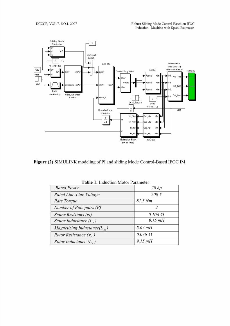
model defined in Eq.s(3) and (4). TheIFOC IM of Fig.(11) is run at sampling
period 62 eT s . The IM used in this
case study has the parameters listed in
table (1)In the following study, the
variation of the motor parameters is
confined to load change only, while theother parameters, e.g. viscous friction
B, are held constant.
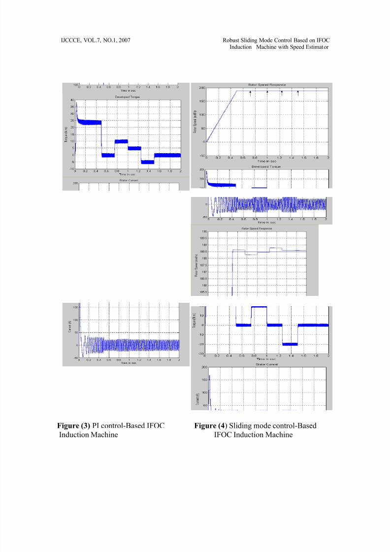
In the first test, the PI controller
is used as a speed controller and a cyclic
change of different load torque levelsare subjected to the machine at certain
times and as follows:
Time = [0 0.75 0.751.0 1.0 1.25 1.25 1.5 1.5 2];
Torque = [0 0 -10
-10 –5 –5 5 5 0 0];
The responses of speed, developed
torque, and stator current are shown inFig.(12). It is evident from the figure
that the PI controller shows bad speedresponse at these applied changes of
loads and lacks the ability to hold the
speed at the required value. Therefore, it
is true to say that the PI controller is notrobust against the changes of IM
parameters. Retuning of the PI
parameters may slightly reduce the
change of speed due to itscorresponding change of load.
In the second test, the slidingmode controller is proposed and a
change of 20 N.m of load applied for
a period of time. For this value of load
level change is found to be 8, and
the value of k is set to be 100. The value
8/12/2019 Sliding Mode Control of I.M
http://slidepdf.com/reader/full/sliding-mode-control-of-im 8/12
IJCCCE, VOL.7, NO.1, 2007 Robust Sliding Mode Control Based on IFOCInduction Machine with Speed Estimator
of limits the value of exerted load,
while the value of k determines the
speed of tracking according to Eq.(34).
The form of this repeated load change
can be clarified as follows:
Time = [0 0.75 0.75
1.0 1.0 1.25 1.25 1.5 1.5 2];
Torque= [0 0 -20 -20 0 0 20 20 0 0];
where the load is exerted in time ranges
[0.75 - 1.0] and [1.25 - 1.5]. The speed
response of Fig.(13) shows no detected
change in the rotor speed at these
ranges, meaning that the sliding mode
controller does well in rejecting the
applied torque; therefore the rotor speed
is by now riding over the slidingtrajectory and the controller is robust
against IM parameter variations.To which extent the controller
can reject the applied load depends on
the value , which has been determined
based on the load level. In the above
case, the value of has been calculatedto be greater than 8 for the sliding modecontroller to reject the load levels less
(greater) than 20 (-20). Otherwise the
controller begins to lack the ability to
reject the values of load level greater
than 20 (or less than –20) unless the
boundary of is increased over the
previous one (8). The strong evident of
this argument is clearly shown inFig.(14), where the exerted load level
exceeded 20 N.m while the value of
is held constant at the value 8. The
speed response deteriorates and a
change in the rotor speed will appear at
time of exerting 25 N.m. Therefore
the boundary of should be released
and should have a new value other than
8 for the controller to manage the newlevel of load change.
8. Conclusion
From the simulated results thefollowing points can be concluded:
The PI controller is notrobust against IM parameter
variations, and as has beenshown the speed response
degrades to different level
of load changes.
The sliding mode
controller can overcome the
problem of systemdegradation, encountered in
PI controller, on thecondition that the sliding
mode controller is well
designed for the specified
level of load changes.
If the load level exceeds
the design specification,
degradation in the speed
response is observed unlessanother design procedure is
adopted.
References
[1] M. A. Denai and S. A. Attia,“Fuzzy
and Neural Control of an InductionMotor,” Int. J. Appl. Math. Comput.
Sci, Vol.12, No. 2, p 221-233, 2002. [2] M. A. Denai and S. A. Attia,
“Intelligent Control of an Induction
Motor,” Int. J. Electric Power
Components and System, 30:409-427,Taylor and Francis Ltd, 2002.
[3] Christopher Edwards and Sarah K.
Spurgeon, “Sliding Mode Control:
Theory and Application," Taylor andFrancis Ltd, 2002.
[4] O. Barambones, A. J. Garrido and F.
J. Maseda,“A Sensorless Robust
Vector Control of Induction MotorDrives," University of Pais Vasco,
2002.
[5] Bimal K. Bose, “Modern Power
Electronics and AC Drive," University of Tennessee, Knoxville,
Prentice Hall, 2001.
8/12/2019 Sliding Mode Control of I.M
http://slidepdf.com/reader/full/sliding-mode-control-of-im 9/12
IJCCCE, VOL.7, NO.1, 2007 Robust Sliding Mode Control Based on IFOCInduction Machine with Speed Estimator
[6] Chee-Mun Ong, “Dynamic
Simulation of Electric Machinery
Using Matlab/Simulink ”, PurdueUniversity, Prentice Hall PTR, 1998.
[7] Dal Y. Ohm, “DynamicModel of Induction Motors for
Vector Control”, Drivetech, Inc.,
Blacksburg, Virginia, 2001.[8] W. Leonhard ,“ Control of
Electrical Drives,” Springer Press,
Berlin, 1996. [9] A. Ouhrouche and C. Volat,
“Simulation of a Direct Field-
Oriented Controller for an Induction
Motor Using MATLAB/SIMULINKSoftware Package”, Proceeding of the
IASTED International Conference
Modeling and Simulation,
Pennsylvania, USA, May 15-17, 2000.
[10] Bilal Akin, “State Estimation
Techniques for Speed Sensorless
Field Oriented Control of Induction
Machine”, Master's thesis, The Middle
East technical university, 2003.
[11] Math Works, Inc., " SIMULINK
user's Guide ," Version 2, Jan 1997.
Figure (1) indirect field-Oriented control of a current regulated PWM inverterinduction motor drive
Hysteresis-Band
Current Controller
*e
qsi
*e
dsi
*
asi*
bsi
*
asi
qde to qds
qds to abc
Speed Controller
I.M.
DC bus
PWM
inverter
*m
Field Weakening
Calculate
,*e
qsi *e
dsi
+
+
+
-
-
-
*emT
*edr
e
Indirect Field Orientation Control
+-
e
r
and
Estimator e
r av
bvcv
ai bi ci
8/12/2019 Sliding Mode Control of I.M
http://slidepdf.com/reader/full/sliding-mode-control-of-im 10/12
IJCCCE, VOL.7, NO.1, 2007 Robust Sliding Mode Control Based on IFOCInduction Machine with Speed Estimator
Figure (2) SIMULINK modeling of PI and sliding Mode Control-Based IFOC IM
Table 1: Induction Motor Parameter
Rated Power 20 hp
Rated Line-Line Voltage 200 V
Rate Torque 81.5 Nm
Number of Pole pairs (P) 2
Stator Resistans (rs) 0.106
Stator Inductance (L s ) 9.15 mH
Magnetizing Inductance(L m ) 8.67 mH Rotor Resistance ( r r ) 0.076
Rotor Inductance (L r ) 9.15 mH
8/12/2019 Sliding Mode Control of I.M
http://slidepdf.com/reader/full/sliding-mode-control-of-im 11/12
IJCCCE, VOL.7, NO.1, 2007 Robust Sliding Mode Control Based on IFOCInduction Machine with Speed Estimator
Figure (3) PI control-Based IFOC Figure (4) Sliding mode control-Based
Induction Machine IFOC Induction Machine

8/12/2019 Sliding Mode Control of I.M
http://slidepdf.com/reader/full/sliding-mode-control-of-im 12/12
IJCCCE, VOL.7, NO.1, 2007 Robust Sliding Mode Control Based on IFOCInduction Machine with Speed Estimator
Figure (5) Sliding mode control-Based IFOC Induction Machine When higher levels of
torque load are exerted