Slides PDF Module 1
174
Syllabus Module 1 Evolution of CAD/CAM and CIM segments of generic CIM, computers and workstation, elements of interactive graphics, input/ out put display, storage devices in CAD - an overview of CIM software - 2D Graphics: line drawing algorithms, DDA line algorithm – circle drawing, bressnham`s circle drawing algorithm– 2D translation, rotation, scaling – clipping -3D Graphics (basic only). Design process – CAD process: wireframe, surface, solid modeling; Engineering analysis; design review & evaluation, automated drafting – CAD hard ware, software, data presentation, CAD software packages
-
Upload
jimingeorge -
Category
Documents
-
view
24 -
download
5
description
ytytytt
Transcript of Slides PDF Module 1
Syllabus
Module 1
Evolution of CAD/CAM and CIM segments of generic CIM, computers and workstation, elements of interactive graphics, input/ out put display, storage devices in CAD - an overview of CIM software - 2D Graphics: line drawing algorithms, DDA line algorithm – circle drawing, bressnham`s circle drawing algorithm– 2D translation, rotation, scaling – clipping -3D Graphics (basic only).
Design process – CAD process: wireframe, surface, solid modeling; Engineering analysis; design review & evaluation, automated drafting – CAD hard ware, software, data presentation, CAD software packages
Syllabus
Module 2
Numerical control: Need - advantages & disadvantages – classifications – Point to point, straight cut & contouring positioning - incremental & absolute systems – open loop & closed loop systems – DDA integrator & Interpolators – resolution – CNC & DNC.
Programmable logic controllers (PLC): need – relays- logic ladder program – timers - Simple exercises only.
Devices in N.C. systems: Driving devices - feed back devices: encoders, moire fringes, digitizer, resolver, inductosyn, tachometer.
Module 3
NC part programming: part programming fundamentals - manual programming – NC co-ordinate systems and axes – tape format – sequence number, preparatory functions, dimension words, speed word, feed world, tool world, miscellaneous functions – programming exercises.
Computer aided part programming: concept & need of CAP – CNC languages – APT language structure: geometry commands, motion commands, postprocessor commands, compilation control commands – programming exercises – programming with interactive graphics.
Syllabus
Module 4
Automated process planning: Process planning, general methodology of group technology, code structures of variant & generative process planning methods, AI in process planning, process planning software.
Module 5
Robotics: Industrial robots and their applications for transformational and handling activities, configuration & motion, actuators, sensors and end effectors, feature like work envelop, precision of movement, weight carrying capacity, robot programming languages.
Vision systems: introduction to intelligent robots.
Reference Books
Craig John - Introduction to Robotics
Groover M.P. - CAD/CAM, PHI.
Hearn & Baker - Computer graphics (in C version), Prentice Hall.
New man & Sproull - Principles of interactive Graphics, McGraw – Hill.
Petruzella Frank.D. - Programmable logic controllers.
Yoram Koren - Numerical control of machine tools, McGraw-Hill
Credits
� 3-1-0 hours (per week)
� 3 hours lecture
� 1 hour tutorial
� 0 hours practical
� Marks
� Series
− Out of 50
� University
− Out of 100
Series Marks distribution
� 60% - Series test
� 30% - Assignments
� Class tests (at the end of each module)
� Pop quiz (written)
� Written assignments
� Presentations
� 10% - Attendance
� Inclusive of written assignments
Examination schedules (tentative)
� I Series − Feb 27th - 29th
� II Series − Mar 28th - 30th
� University Exam − May - June
Module 1
� Evolution of CAD/CAM and CIM segments of generic CIM
� Computers and Workstation
� Elements of interactive graphics in CAD
� Input/ out put
� Display
� Storage devices
� An overview of CIM software
� 2D Graphics
� Line drawing algorithms
− DDA line algorithm
� Circle drawing
− Bressnham`s circle drawing algorithm
� 2D translation
− rotation, scaling
− Clipping
� 3D Graphics (basics only)
Module 1
� Design process
� CAD process
− Wireframe
− Surface
− Solid modeling
� Engineering analysis
− Design review & evaluation
− Automated drafting
� CAD hard ware, software, data presentation
� CAD software packages
Reference:
1. Groover M.P. - CAD/CAM, PHI.
2. Groover M.P. / Zimmers E.W - CAD/CAM, PHI.
What is CAD/CAM?
� Use of computers to enhance certain functions of design and production
� CAD – Computer Aided Design / Computer Aided Drafting
�Use of computer systems to assist in the creation, modification, analysis, or optimization of a design
� CAM – Computer Aided Manufacturing
�Use of computer systems to plan, manage, and control the operations of a manufacturing plant
� Interface with the plant's production resources
�Direct or Indirect
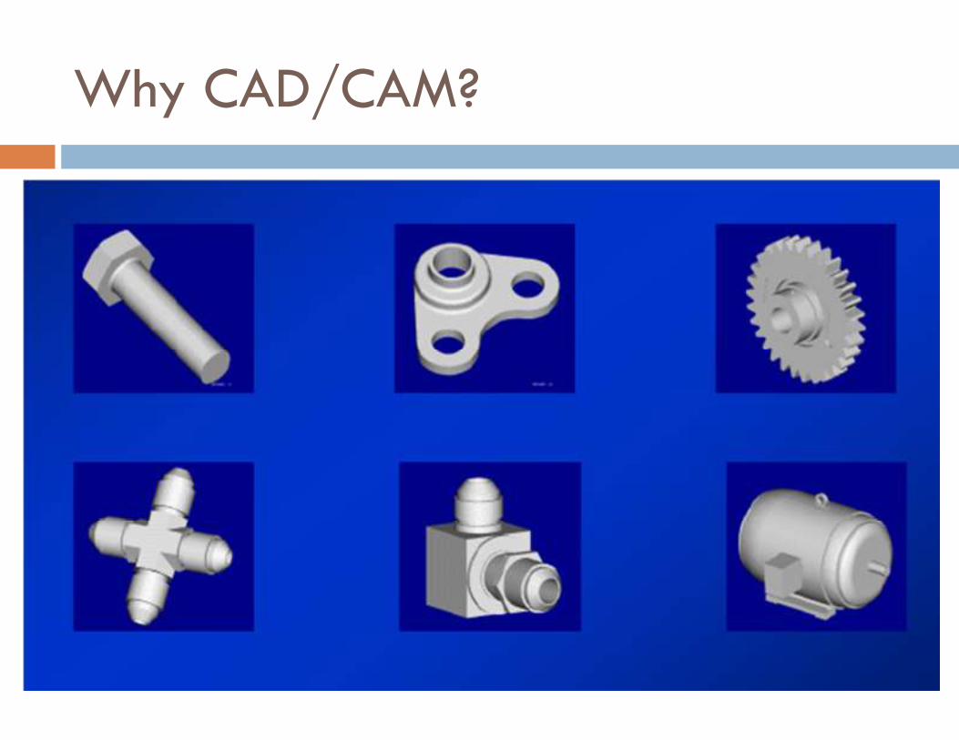
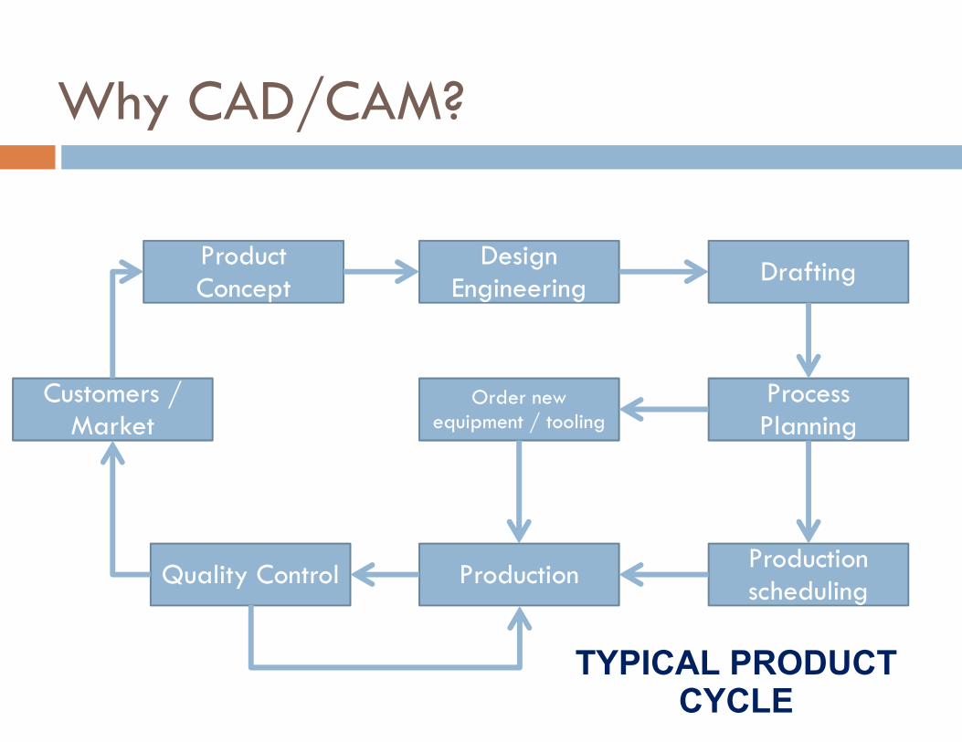
Why CAD/CAM?
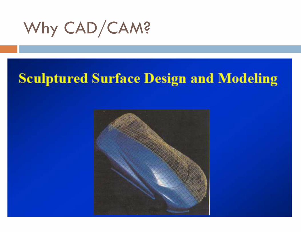
Why CAD/CAM?
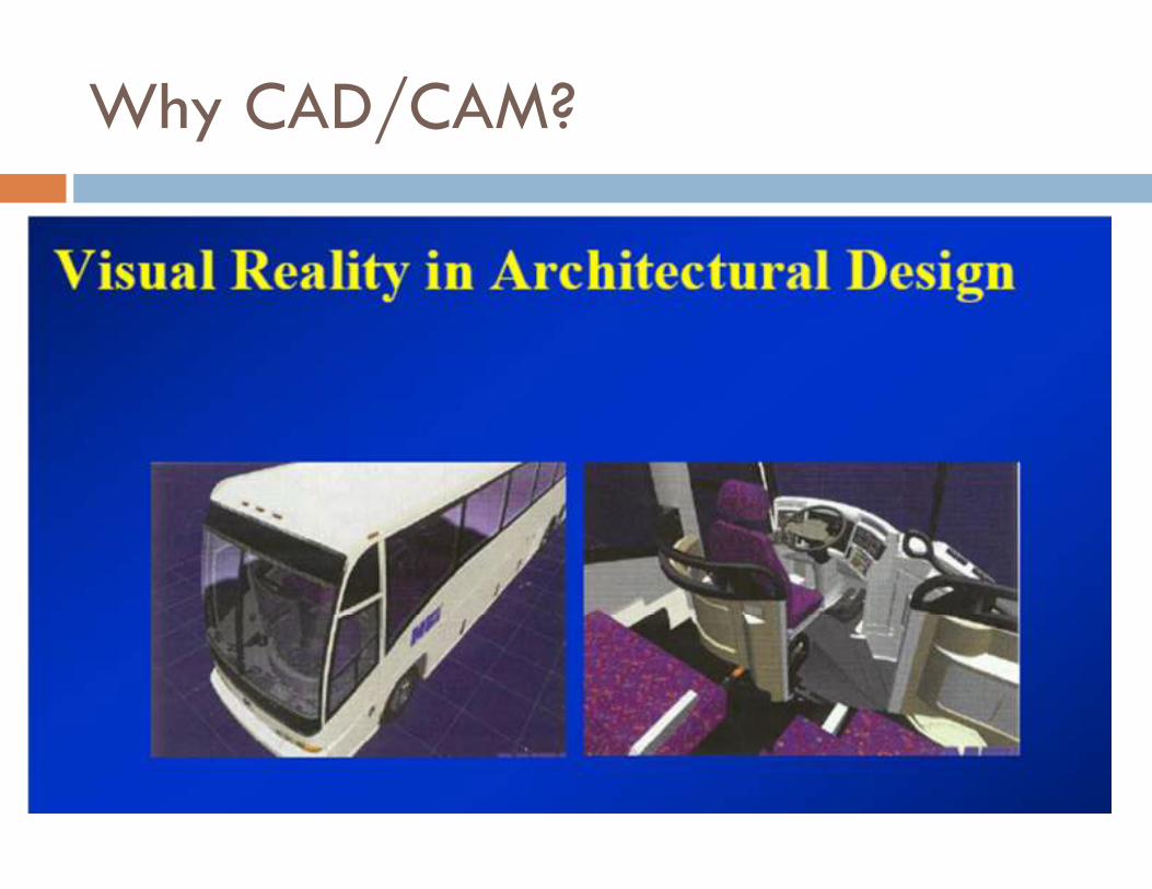
Why CAD/CAM?
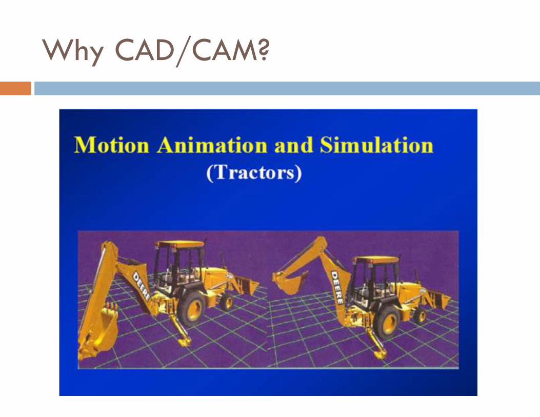
Why CAD/CAM?
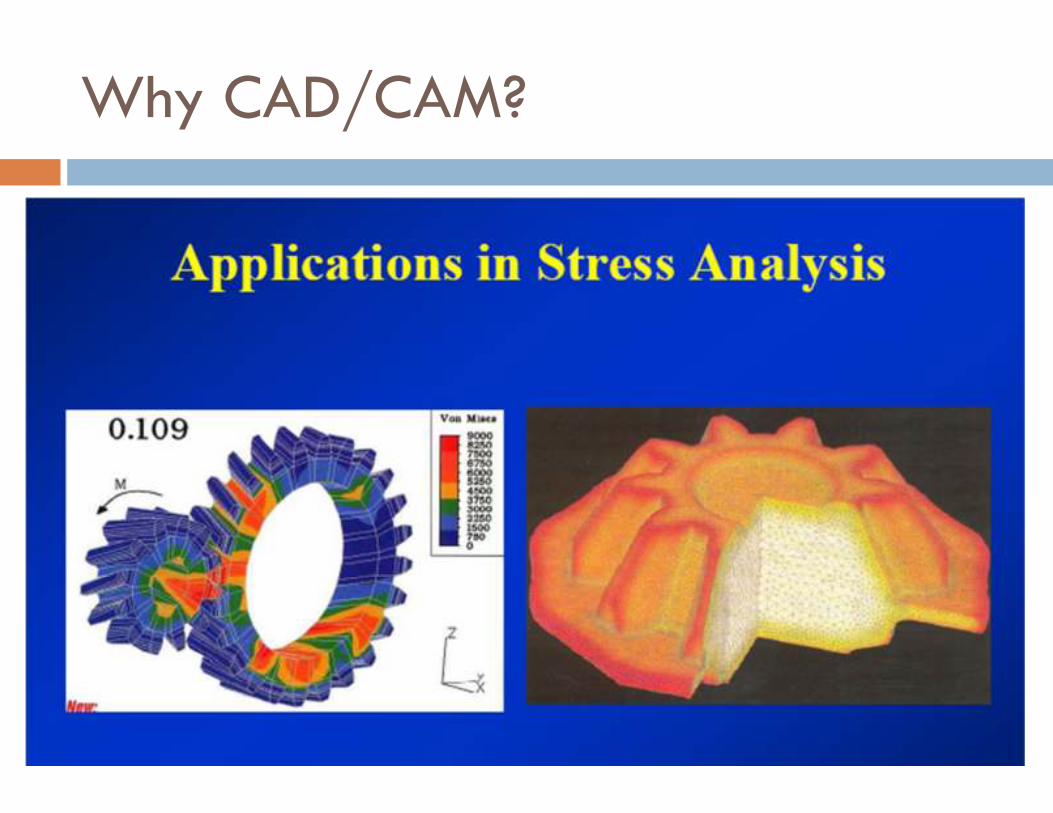
Why CAD/CAM?
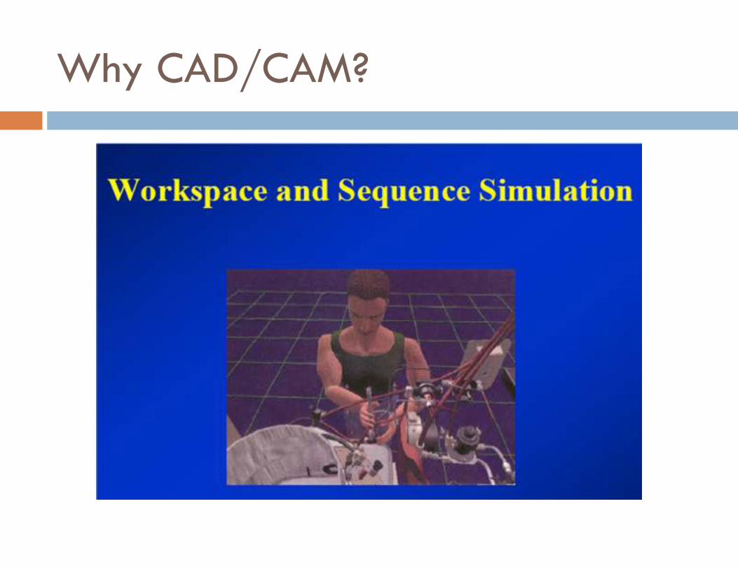
Why CAD/CAM?
Why CAD/CAM?
Product Concept
Design Engineering
Drafting
Process Planning
Order new equipment / tooling
Production scheduling
Production Quality Control
Customers / Market
TYPICAL PRODUCT
CYCLE
Product Concept
Design Engineering
Drafting
Process Planning
Order new equipment / tooling
Production scheduling
Production Quality Control
Customers / Market
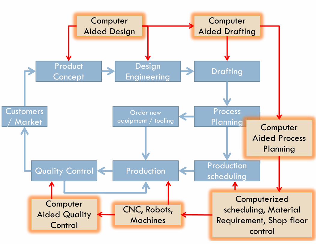
Computer Aided Design
Computer Aided Design
Computer Aided Drafting
Computer Aided Drafting
Computer Aided Process
Planning
CNC, Robots, Machines
CNC, Robots, Machines
Computerized scheduling, Material
Requirement, Shop floor control
Computer
Control
Computer Aided Quality
Control
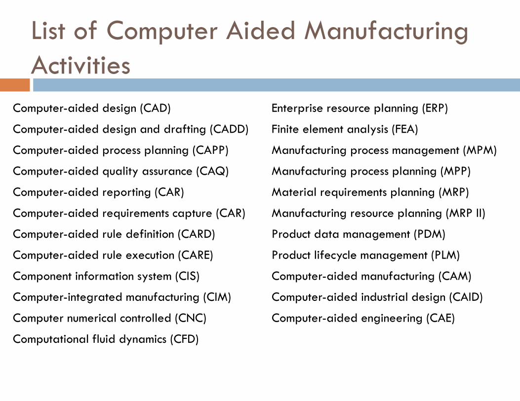
List of Computer Aided Manufacturing Activities
Computer-aided design (CAD)
Computer-aided design and drafting (CADD)
Computer-aided process planning (CAPP)
Computer-aided quality assurance (CAQ)
Computer-aided reporting (CAR)
Computer-aided requirements capture (CAR)
Computer-aided rule definition (CARD)
Computer-aided rule execution (CARE)
Component information system (CIS)
Computer-integrated manufacturing (CIM)
Computer numerical controlled (CNC)
Computational fluid dynamics (CFD)
Enterprise resource planning (ERP)
Finite element analysis (FEA)
Manufacturing process management (MPM)
Manufacturing process planning (MPP)
Material requirements planning (MRP)
Manufacturing resource planning (MRP II)
Product data management (PDM)
Product lifecycle management (PLM)
Computer-aided manufacturing (CAM)
Computer-aided industrial design (CAID)
Computer-aided engineering (CAE)
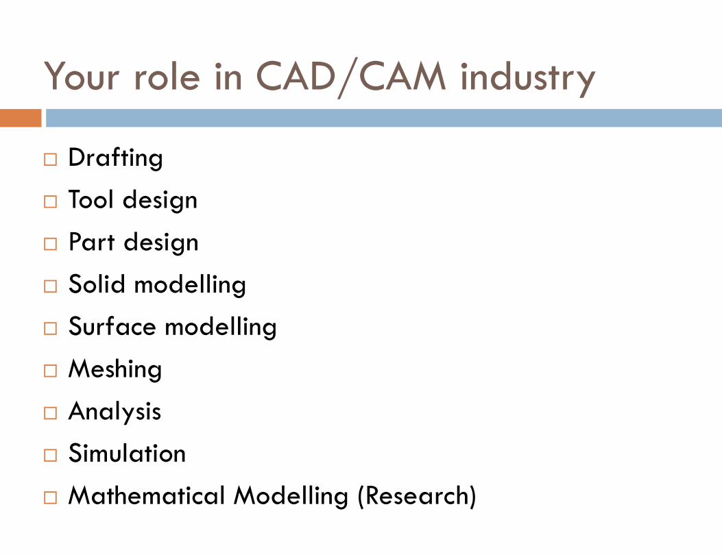
Your role in CAD/CAM industry
� Drafting
� Tool design
� Part design
� Solid modelling
� Surface modelling
� Meshing
� Analysis
� Simulation
� Mathematical Modelling (Research)
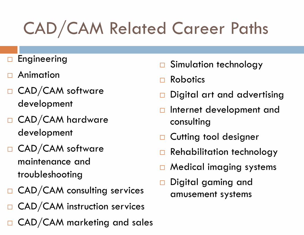
CAD/CAM Related Career Paths
� Engineering
� Animation
� CAD/CAM software development
� CAD/CAM hardware development
� CAD/CAM software maintenance and troubleshooting
� CAD/CAM consulting services
� CAD/CAM instruction services
� CAD/CAM marketing and sales
� Simulation technology
� Robotics
� Digital art and advertising
� Internet development and consulting
� Cutting tool designer
� Rehabilitation technology
� Medical imaging systems
� Digital gaming and amusement systems
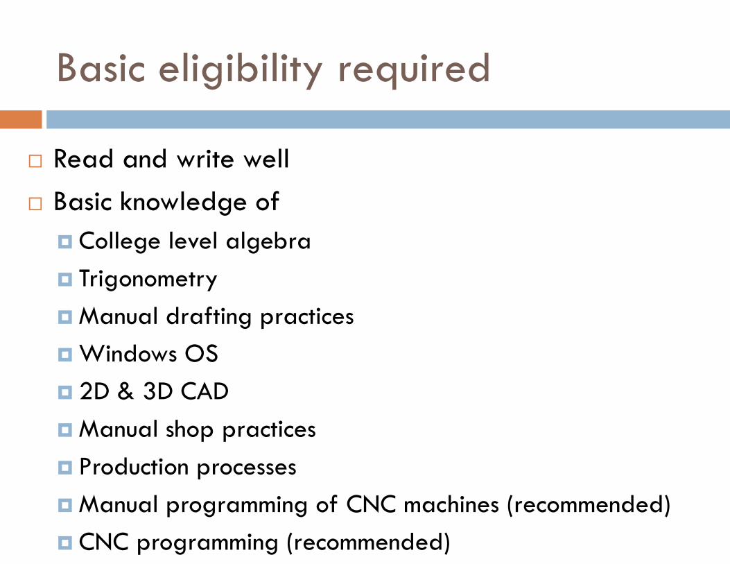
Basic eligibility required
� Read and write well
� Basic knowledge of
� College level algebra
� Trigonometry
� Manual drafting practices
� Windows OS
� 2D & 3D CAD
� Manual shop practices
� Production processes
� Manual programming of CNC machines (recommended)
� CNC programming (recommended)
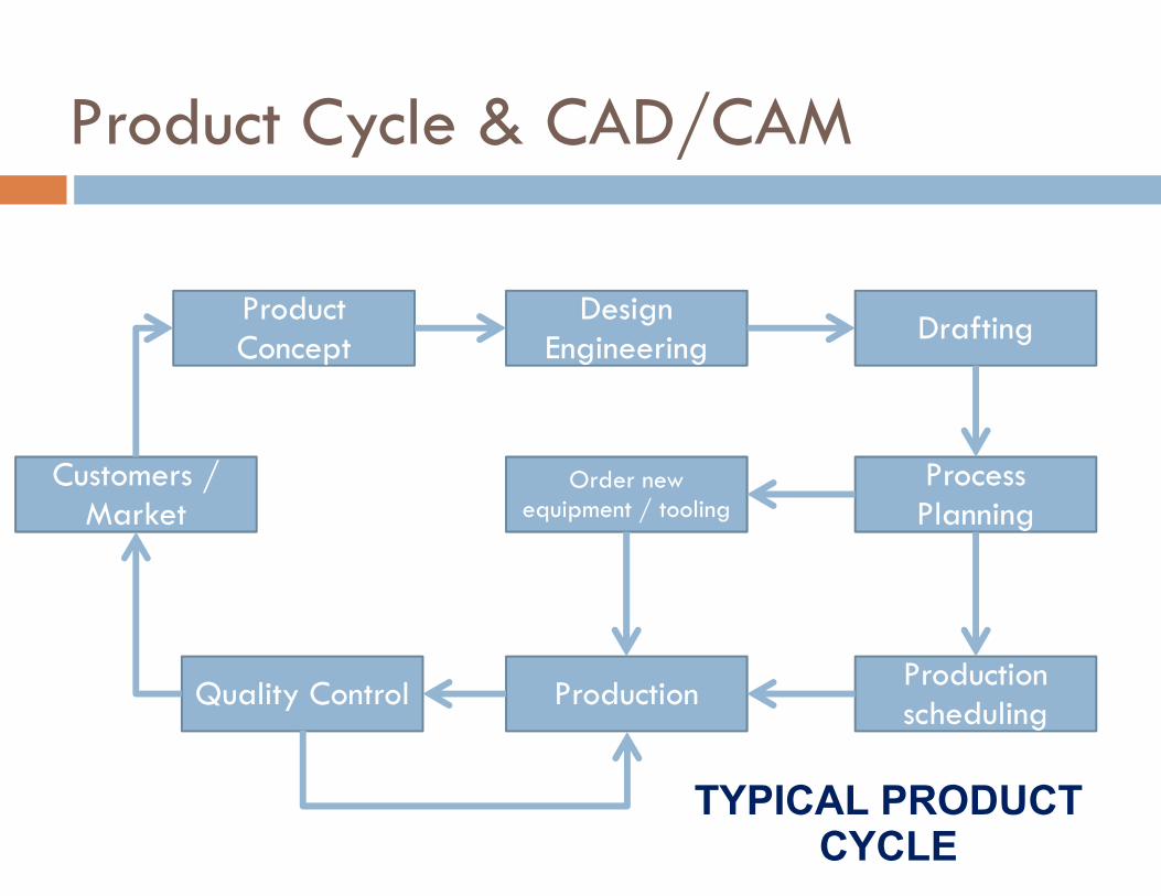
Product Cycle & CAD/CAM
Product Concept
Design Engineering
Drafting
Process Planning
Order new equipment / tooling
Production scheduling
Production Quality Control
Customers / Market
TYPICAL PRODUCT
CYCLE

Product Concept
Design Engineering
Drafting
Process Planning
Order new equipment / tooling
Production scheduling
Production Quality Control
Customers / Market
Computer Aided Design
Computer Aided Design
Computer Aided Drafting
Computer Aided Drafting
Computer Aided Process
Planning
CNC, Robots, Machines
CNC, Robots, Machines
Computerized scheduling, Material
Requirement, Shop floor control
Computer
Control
Computer Aided Quality
Control
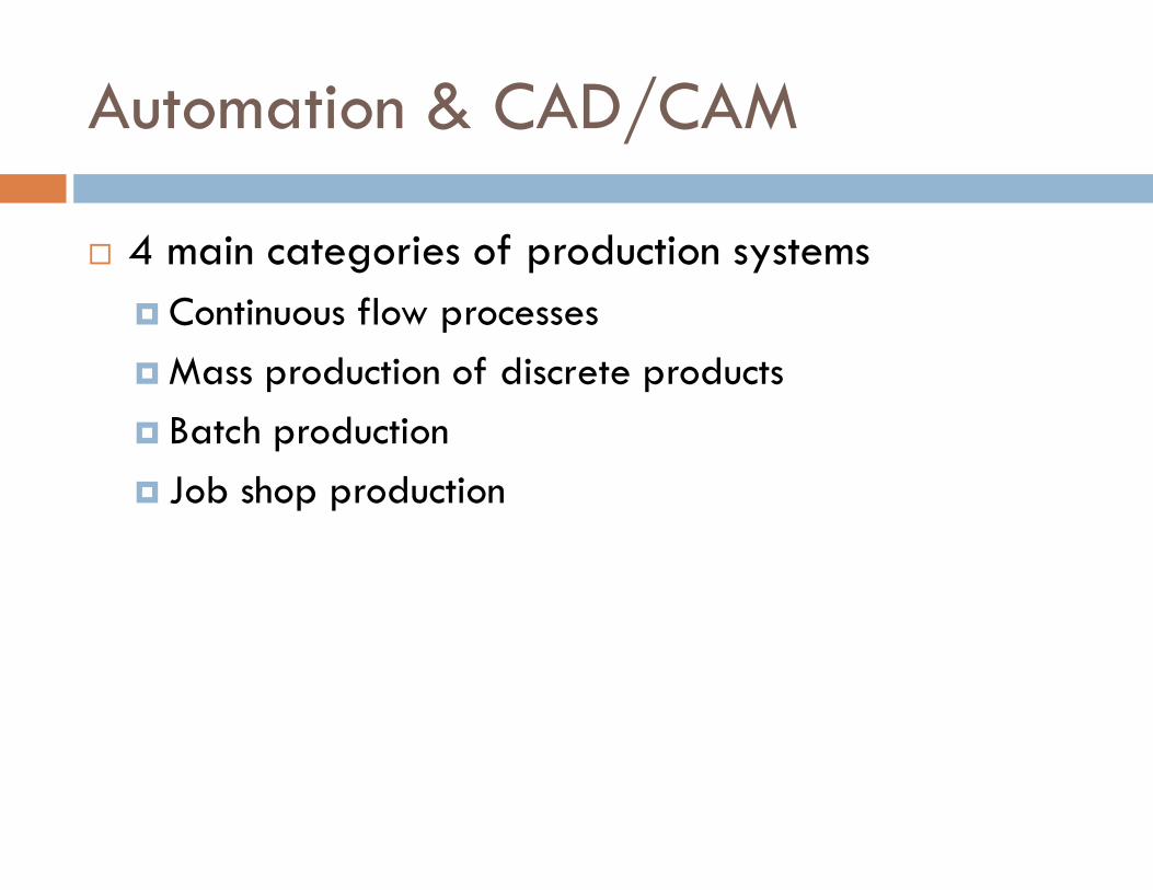
Automation & CAD/CAM
� 4 main categories of production systems
� Continuous flow processes
� Mass production of discrete products
� Batch production
� Job shop production
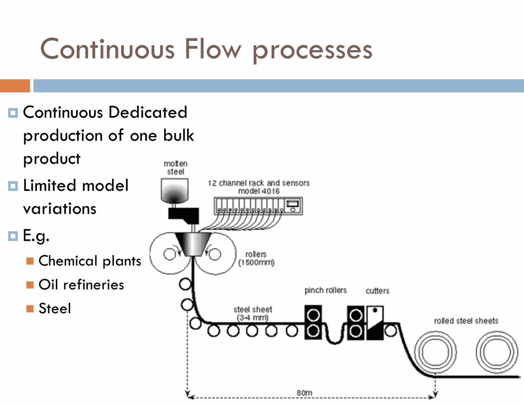
Continuous Flow processes
� Continuous Dedicated production of one bulk product
� Limited model variations
� E.g.
� Chemical plants
� Oil refineries
� Steel
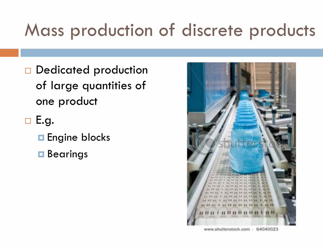
Mass production of discrete products
� Dedicated production of large quantities of one product
� E.g.
� Engine blocks
� Bearings
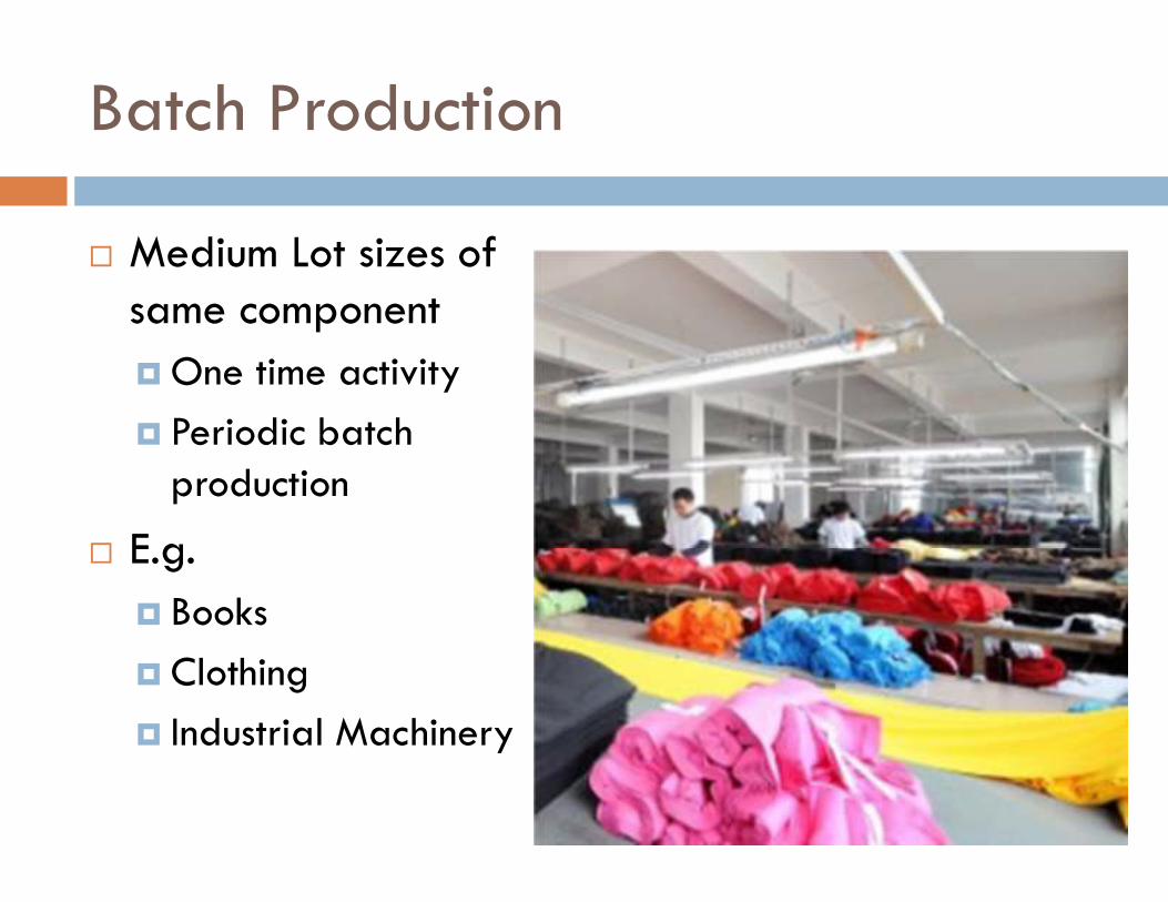
Batch Production
� Medium Lot sizes of same component
� One time activity
� Periodic batch production
� E.g.
� Books
� Clothing
� Industrial Machinery
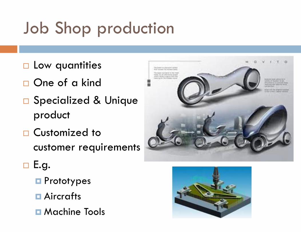
Job Shop production
� Low quantities
� One of a kind
� Specialized & Unique product
� Customized to customer requirements
� E.g.
� Prototypes
� Aircrafts
� Machine Tools
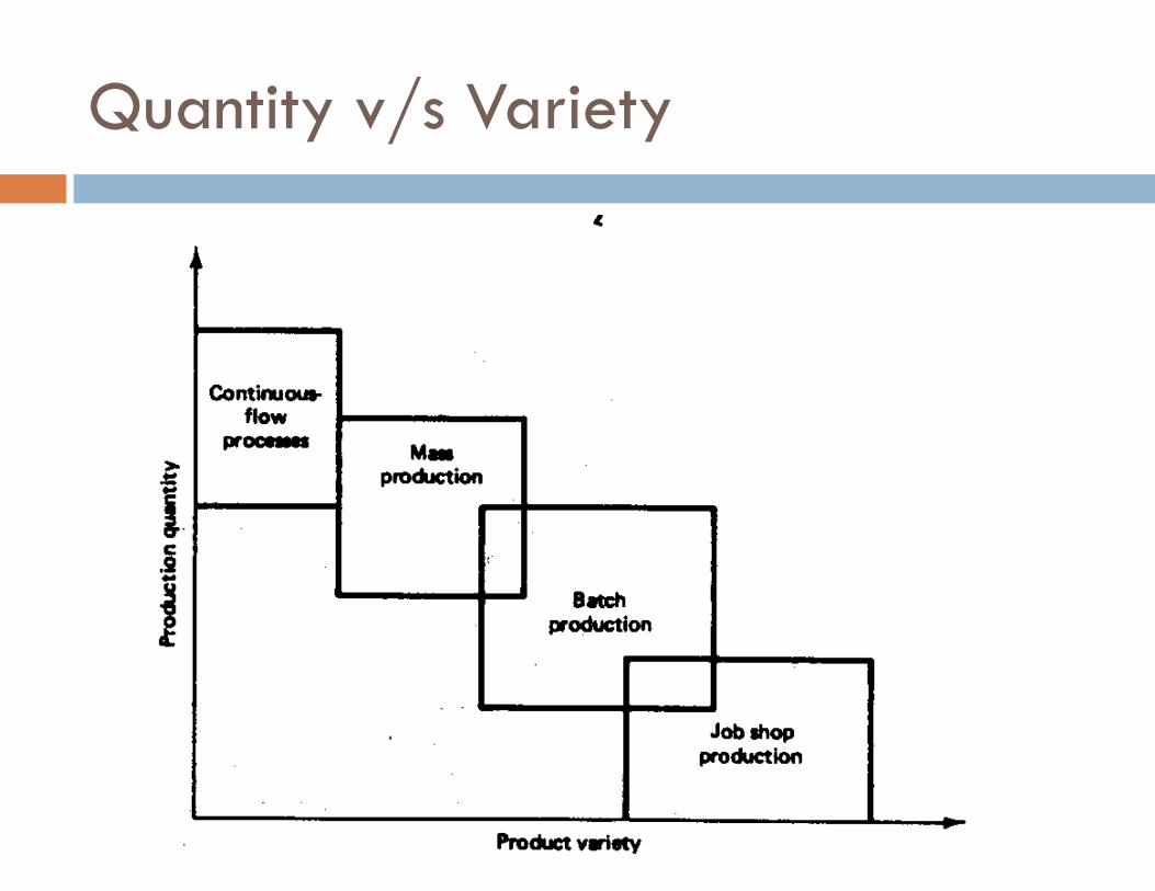
Quantity v/s Variety
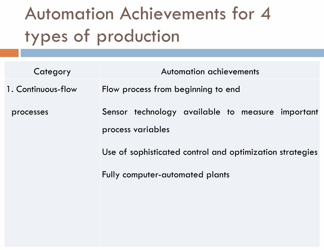
Category Automation achievements
1. Continuous-flow
processes
Flow process from beginning to end
Sensor technology available to measure important
process variables
Use of sophisticated control and optimization strategies
Fully computer-automated plants
Automation Achievements for 4 types of production
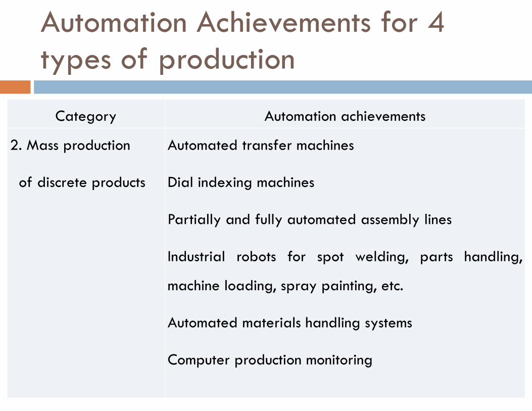
Category Automation achievements
2. Mass production
of discrete products
Automated transfer machines
Dial indexing machines
Partially and fully automated assembly lines
Industrial robots for spot welding, parts handling,
machine loading, spray painting, etc.
Automated materials handling systems
Computer production monitoring
Automation Achievements for 4 types of production
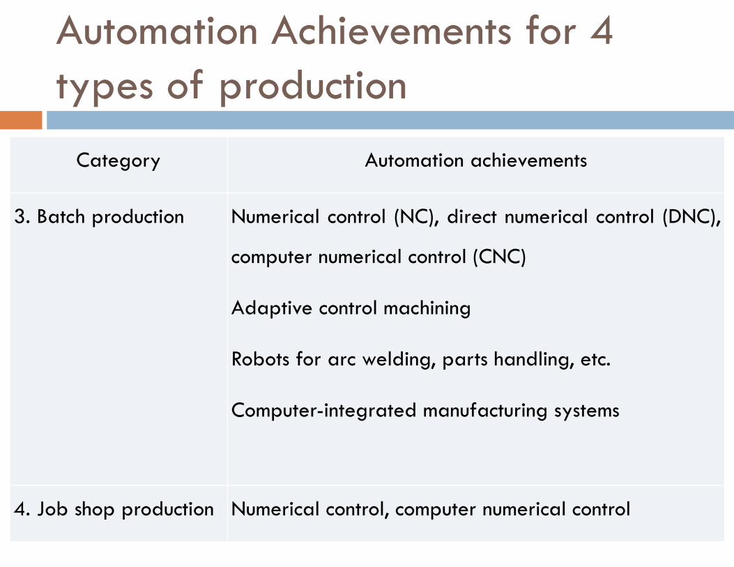
Category Automation achievements
3. Batch production Numerical control (NC), direct numerical control (DNC),
computer numerical control (CNC)
Adaptive control machining
Robots for arc welding, parts handling, etc.
Computer-integrated manufacturing systems
4. Job shop production Numerical control, computer numerical control
Automation Achievements for 4 types of production
What is CAD?
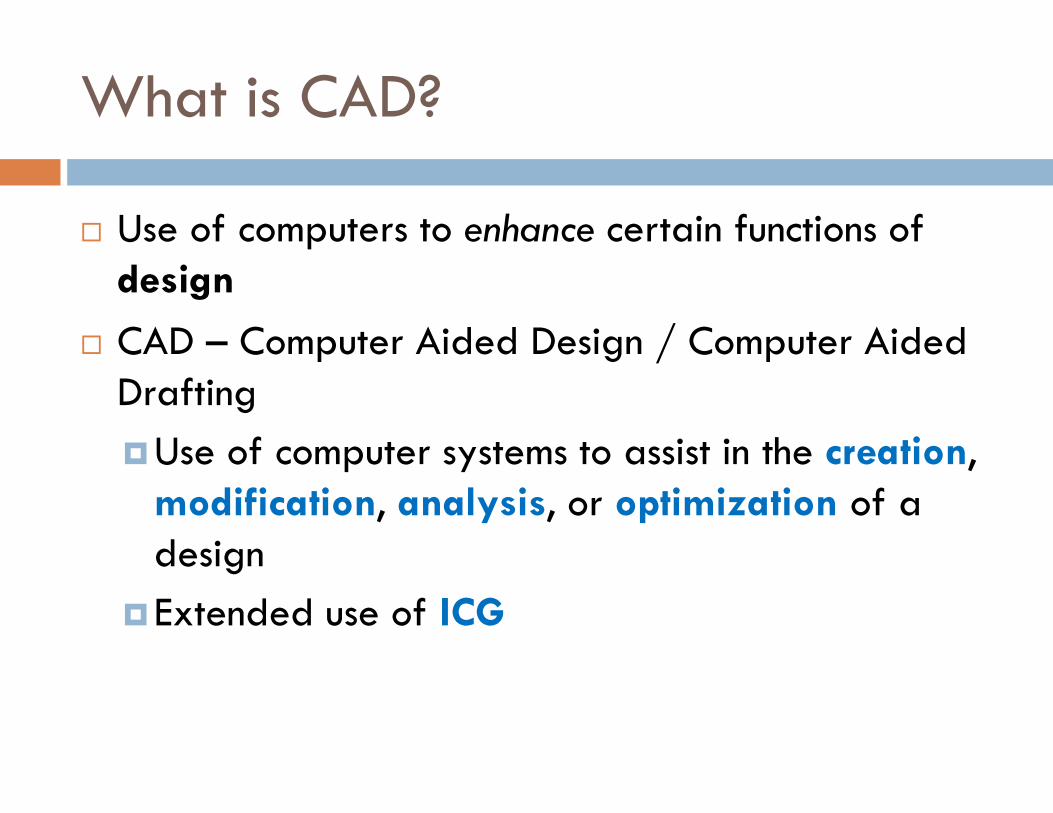
� Use of computers to enhance certain functions of design
� CAD – Computer Aided Design / Computer Aided Drafting
�Use of computer systems to assist in the creation, modification, analysis, or optimization of a design
�Extended use of ICG
ICG
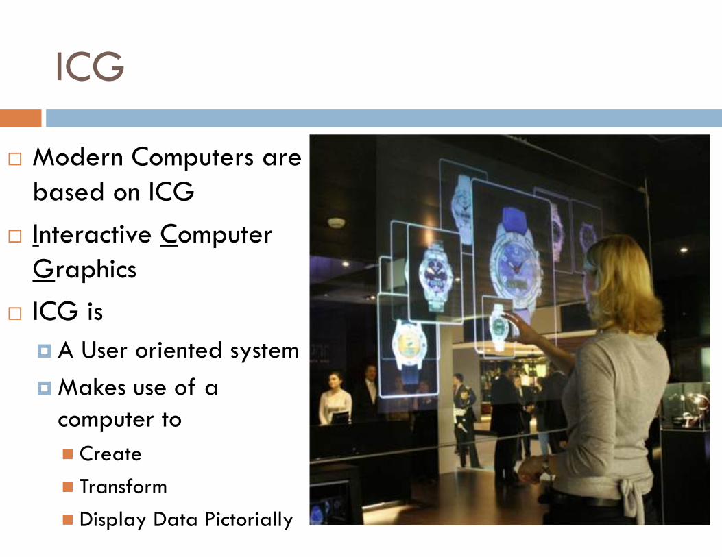
� Modern Computers are based on ICG
� Interactive Computer Graphics
� ICG is
� A User oriented system
� Makes use of a computer to
� Create
� Transform
� Display Data Pictorially
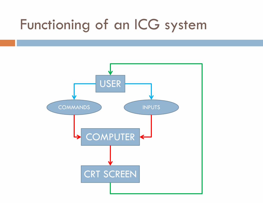
Functioning of an ICG system
USER
COMPUTER
COMMANDS INPUTS
CRT SCREEN
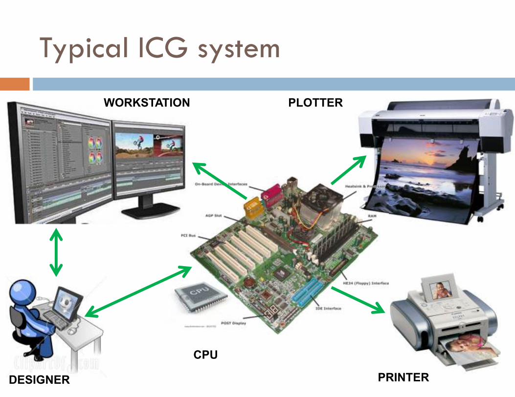
Typical ICG system
WORKSTATION
DESIGNER
CPU
PLOTTER
PRINTER
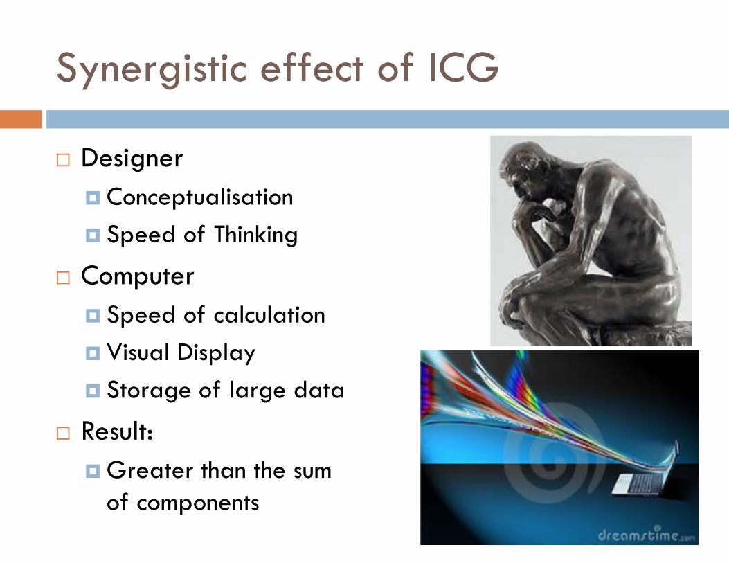
Synergistic effect of ICG
� Designer
� Conceptualisation
� Speed of Thinking
� Computer
� Speed of calculation
� Visual Display
� Storage of large data
� Result:
� Greater than the sum of components
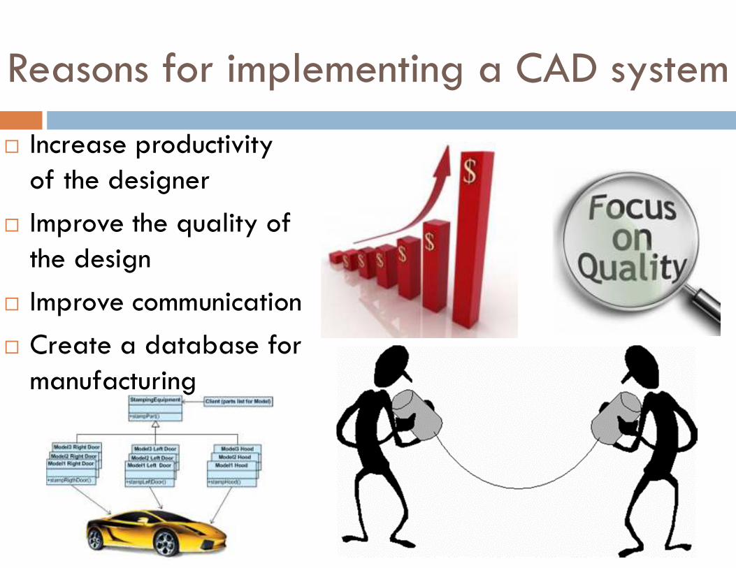
Reasons for implementing a CAD system
� Increase productivity of the designer
� Improve the quality of the design
� Improve communication
� Create a database for manufacturing
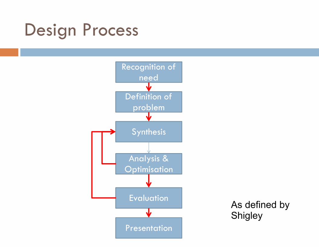
Design Process
As defined by Shigley
Recognition of need
Definition of problem
Synthesis
Analysis & Optimisation
Evaluation
Presentation

1. Recognition of a need
� Realisation that a problem exists
� Corrective action needs to be taken
� New product market opportunity
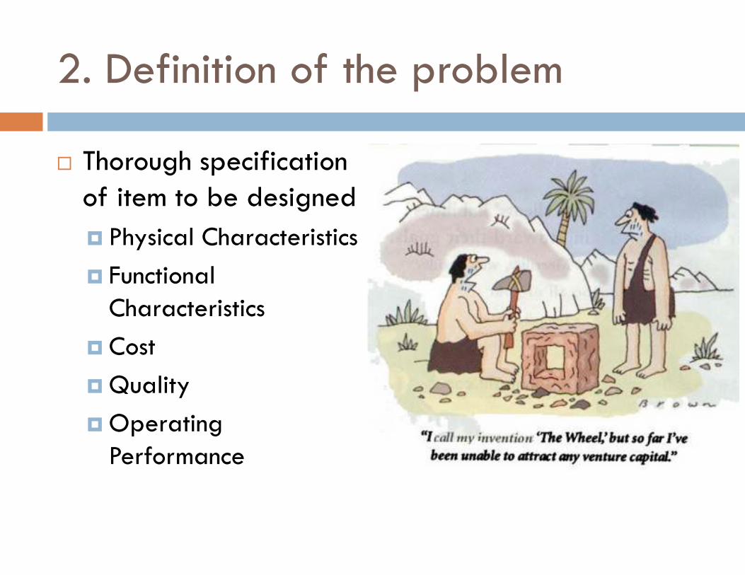
2. Definition of the problem
� Thorough specification of item to be designed
� Physical Characteristics
� Functional Characteristics
� Cost
� Quality
� Operating Performance
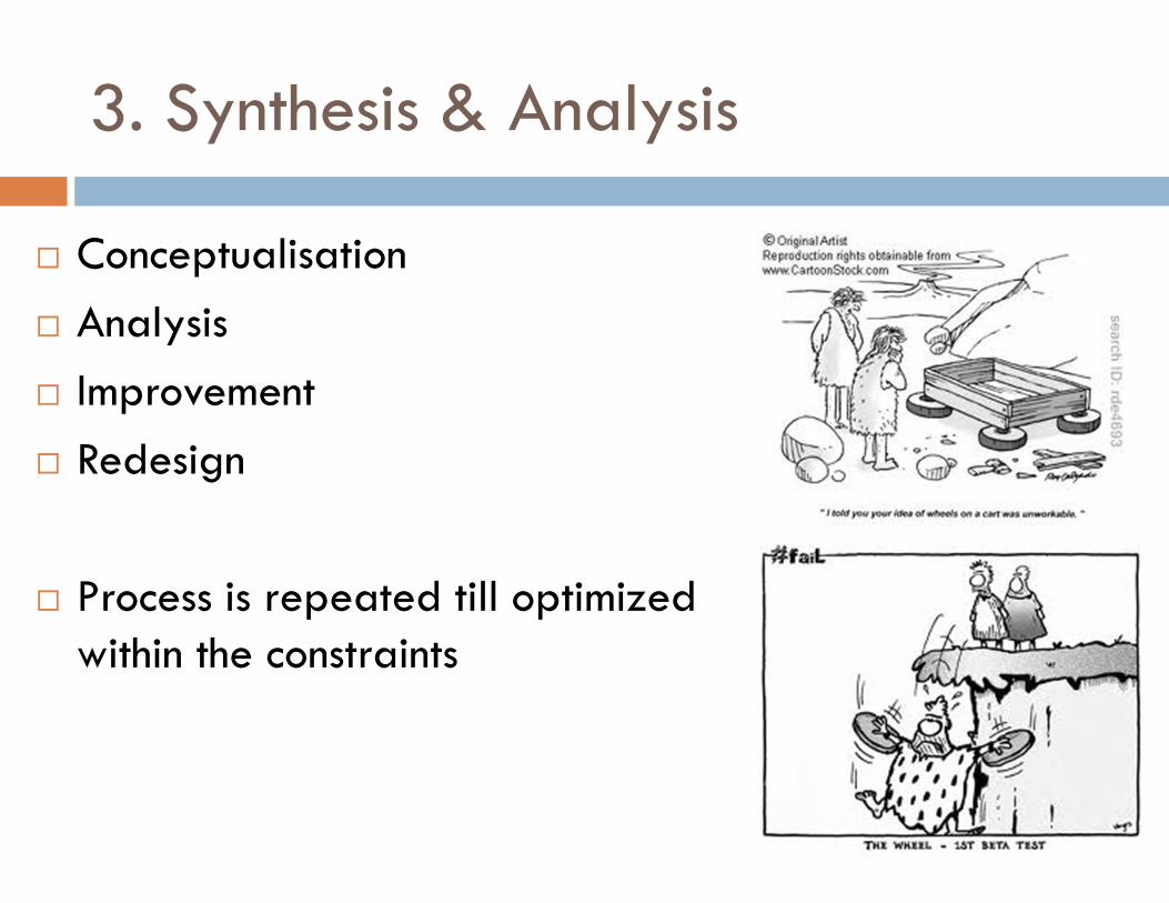
3. Synthesis & Analysis
� Conceptualisation
� Analysis
� Improvement
� Redesign
� Process is repeated till optimized within the constraints
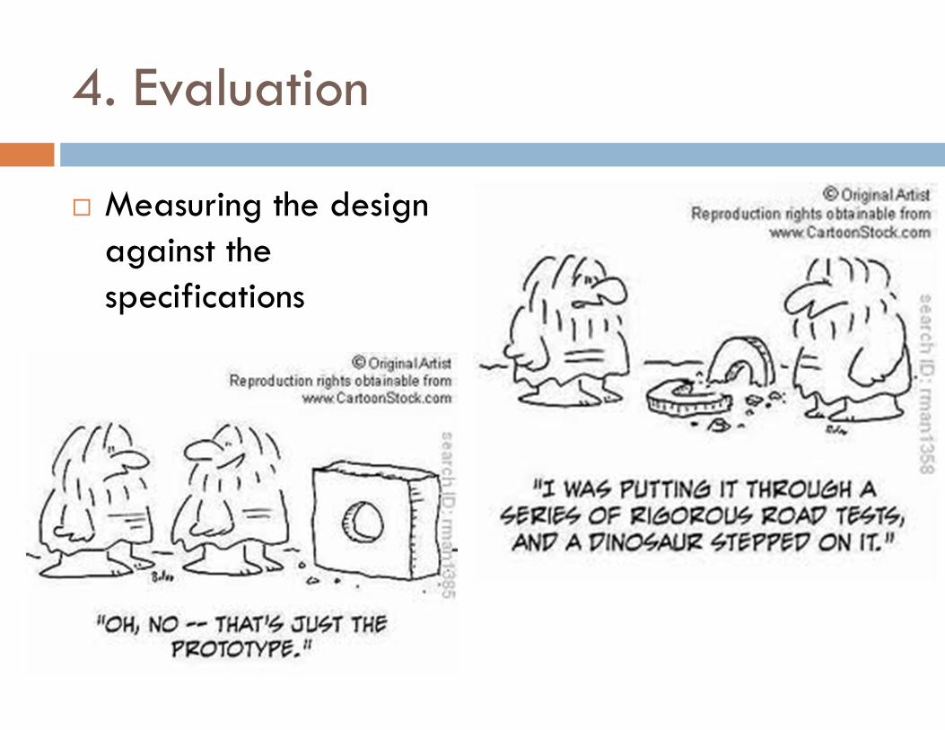
4. Evaluation
� Measuring the design against the specifications
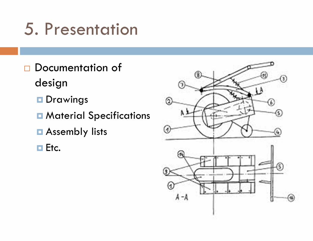
5. Presentation
� Documentation of design
� Drawings
� Material Specifications
� Assembly lists
� Etc.
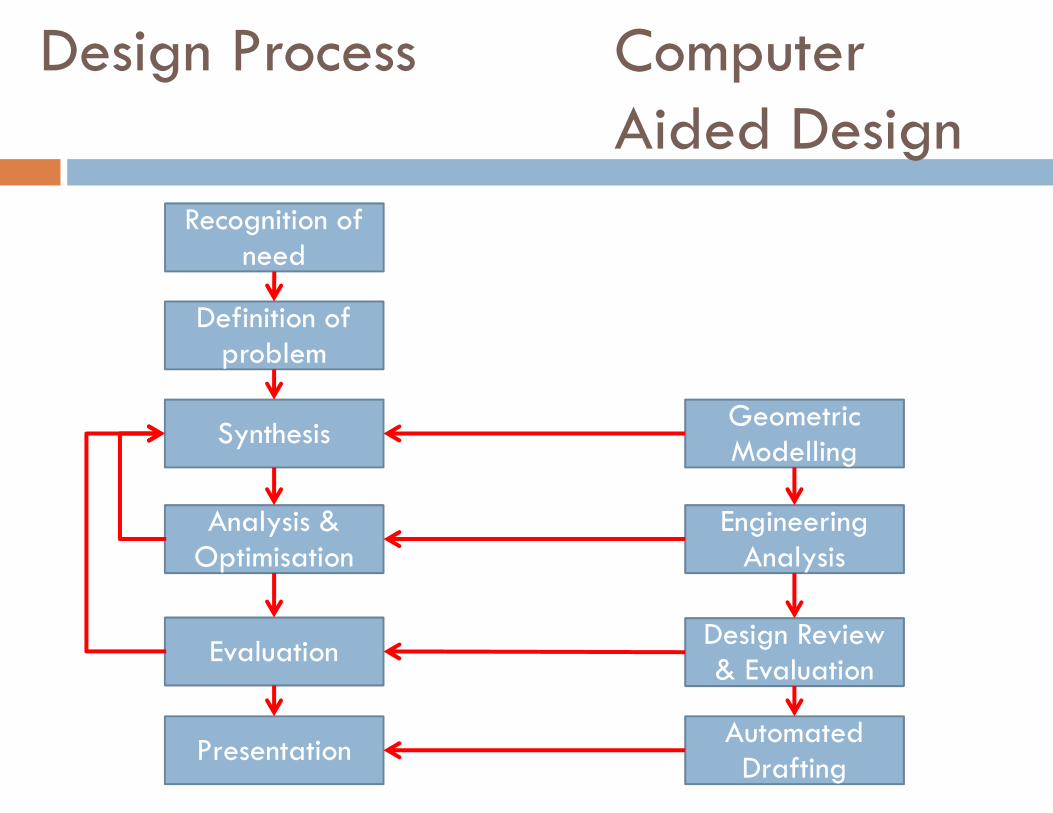
Design Process Computer Aided Design
Recognition of need
Definition of problem
Synthesis
Analysis & Optimisation
Evaluation
Presentation
Geometric Modelling
Engineering Analysis
Design Review & Evaluation
Automated Drafting
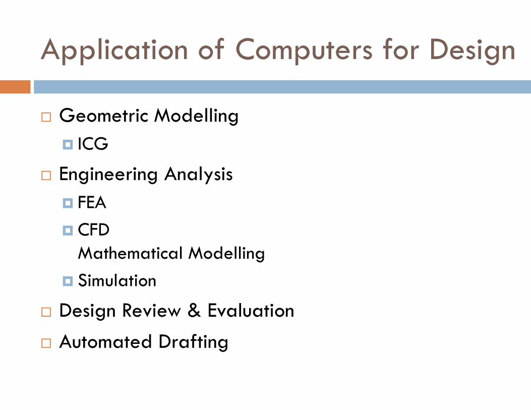
Application of Computers for Design
� Geometric Modelling
� ICG
� Engineering Analysis
� FEA
� CFD Mathematical Modelling
� Simulation
� Design Review & Evaluation
� Automated Drafting
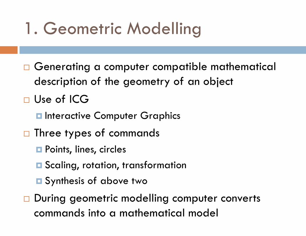
1. Geometric Modelling
� Generating a computer compatible mathematical description of the geometry of an object
� Use of ICG
� Interactive Computer Graphics
� Three types of commands
� Points, lines, circles
� Scaling, rotation, transformation
� Synthesis of above two
� During geometric modelling computer converts commands into a mathematical model
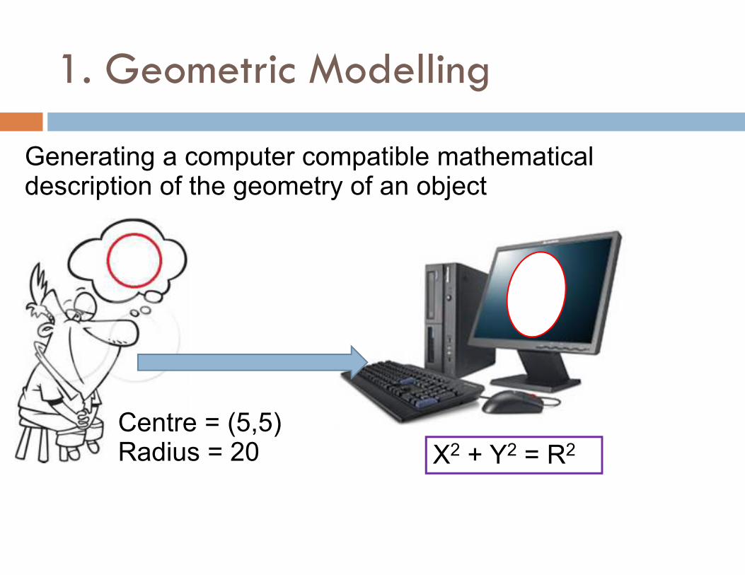
1. Geometric Modelling
Centre = (5,5) Radius = 20 X2 + Y2 = R2
Generating a computer compatible mathematical description of the geometry of an object
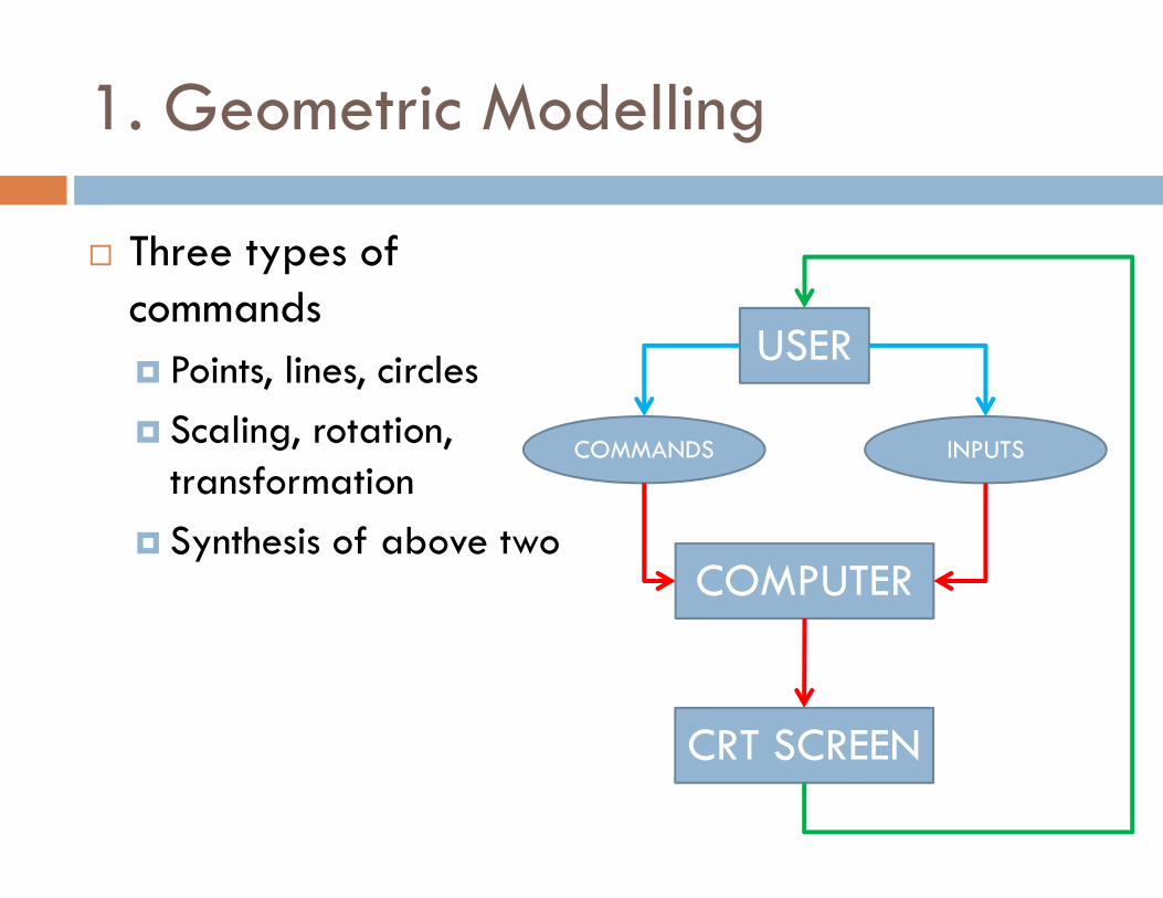
1. Geometric Modelling
� Three types of commands
� Points, lines, circles
� Scaling, rotation, transformation
� Synthesis of above two
USER
COMPUTER
COMMANDS INPUTS
CRT SCREEN
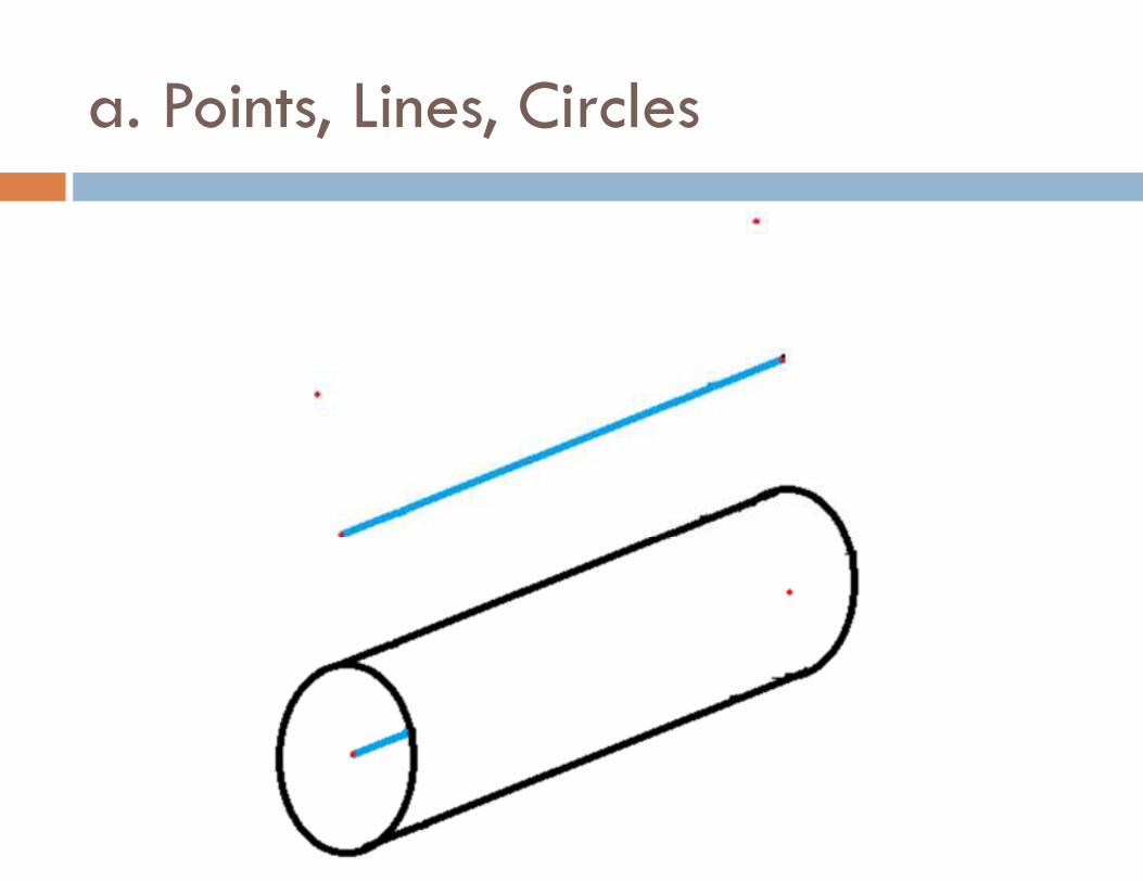
a. Points, Lines, Circles
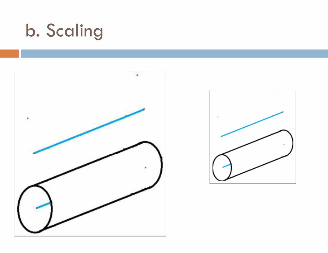
b. Scaling
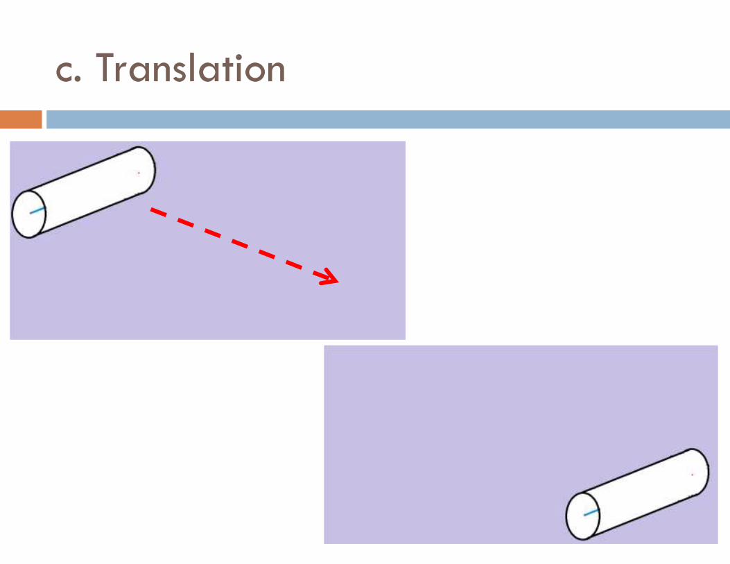
c. Translation
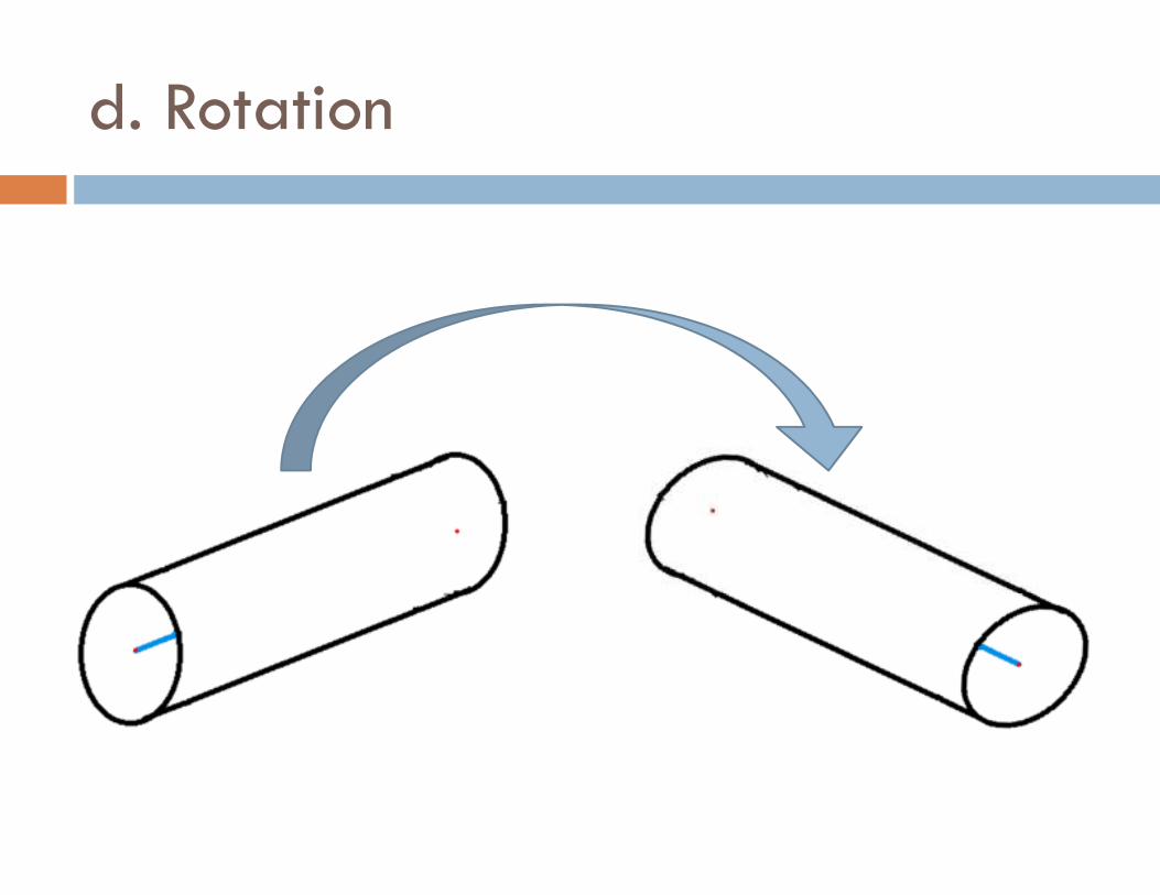
d. Rotation

Types of representing an object
� Wireframe
� 2D
� 2.5 D
� 3D
� Solid Model
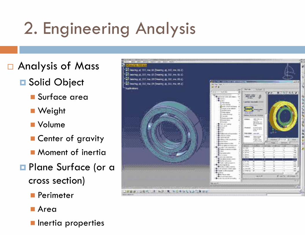
2. Engineering Analysis
� Analysis of Mass
� Solid Object
� Surface area
� Weight
� Volume
� Center of gravity
� Moment of inertia
� Plane Surface (or a cross section)
� Perimeter
� Area
� Inertia properties
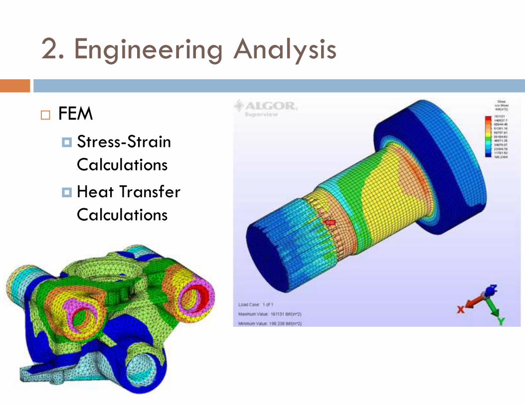
2. Engineering Analysis
� FEM
� Stress-Strain Calculations
� Heat Transfer Calculations
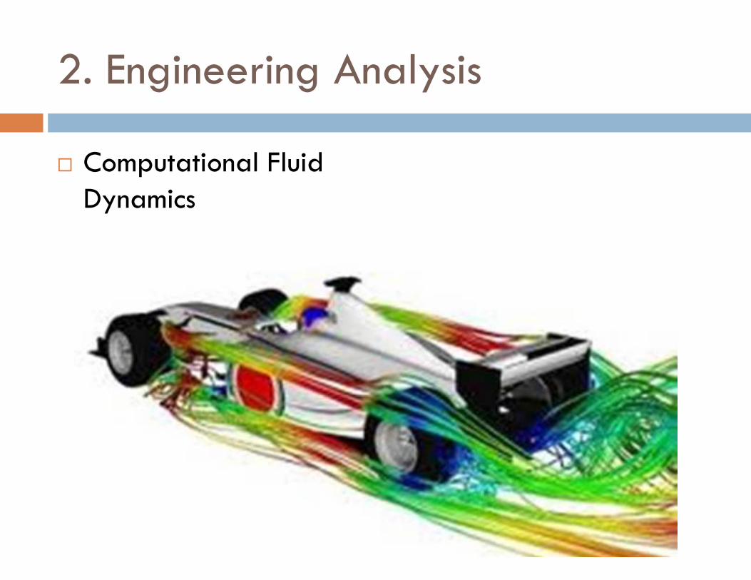
2. Engineering Analysis
� Computational Fluid Dynamics
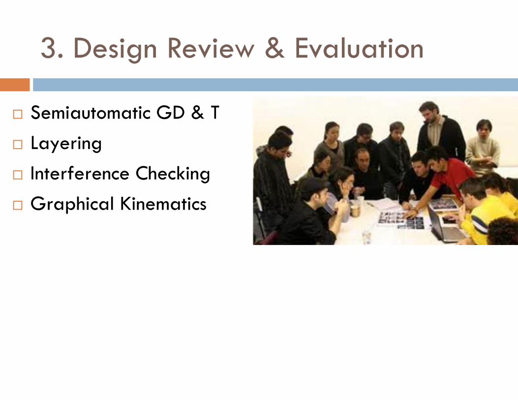
3. Design Review & Evaluation
� Semiautomatic GD & T
� Layering
� Interference Checking
� Graphical Kinematics
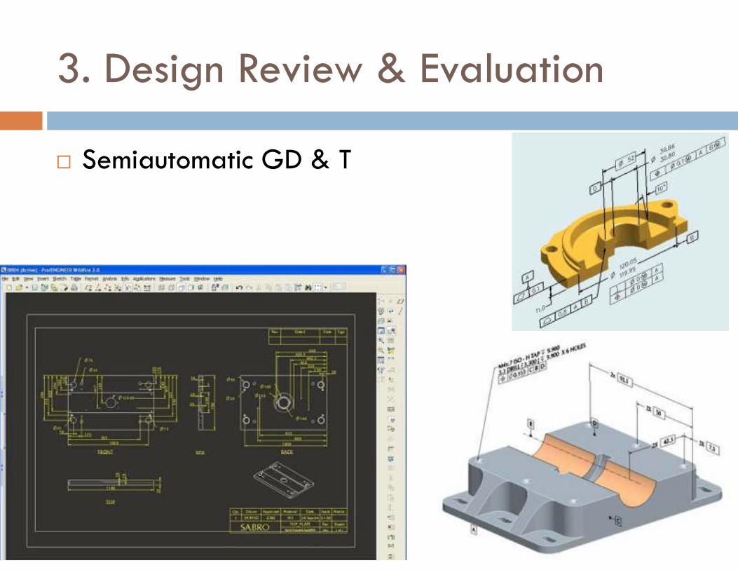
3. Design Review & Evaluation
� Semiautomatic GD & T
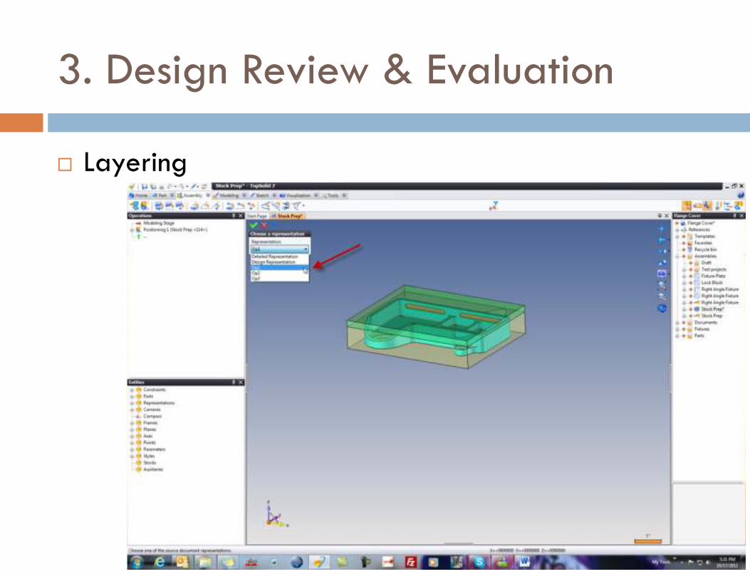
3. Design Review & Evaluation
� Layering
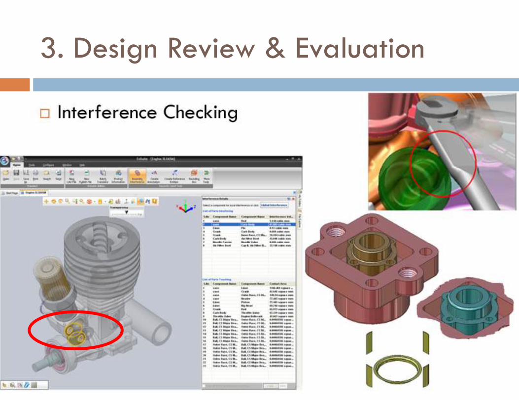
3. Design Review & Evaluation
� Interference Checking
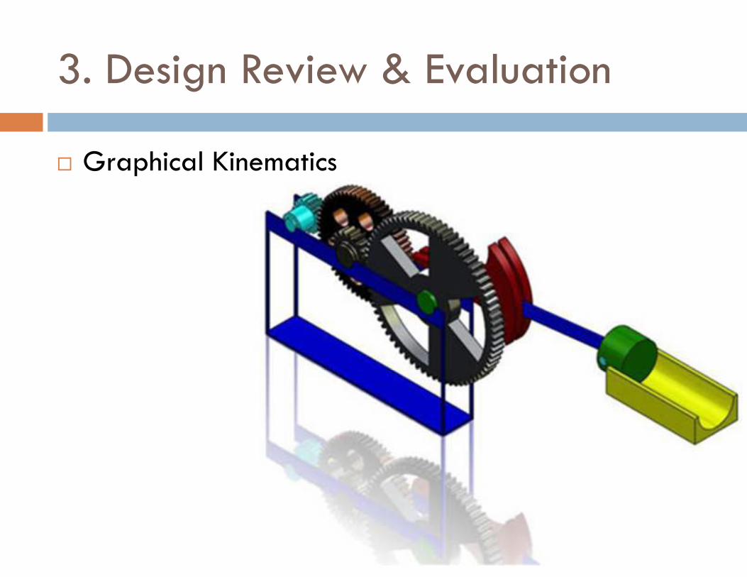
3. Design Review & Evaluation
� Graphical Kinematics
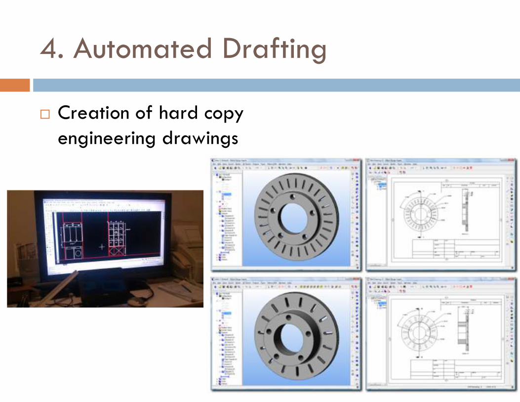
4. Automated Drafting
� Creation of hard copy engineering drawings
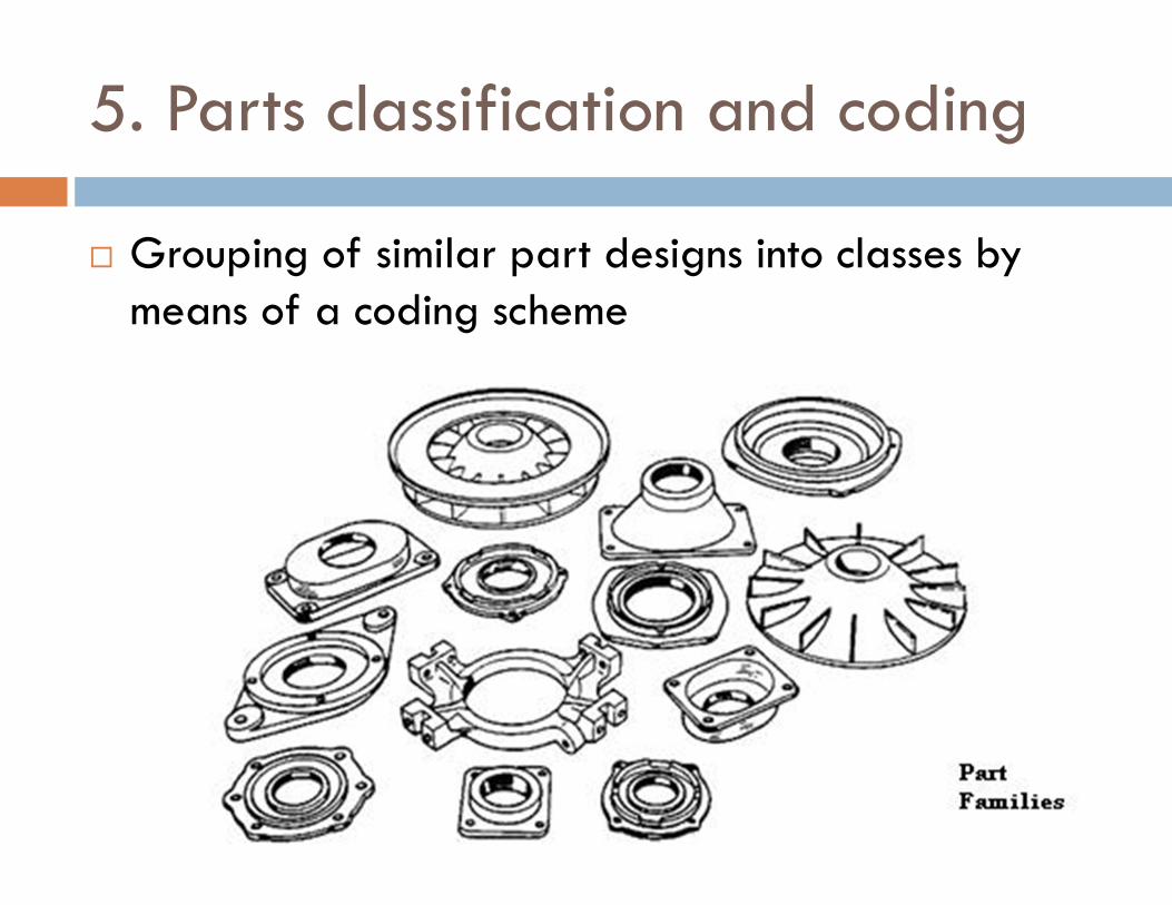
5. Parts classification and coding
� Grouping of similar part designs into classes by means of a coding scheme
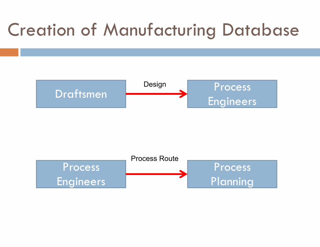
Creation of Manufacturing Database
Draftsmen Process
Engineers
Process Engineers
Process Planning
Design
Process Route
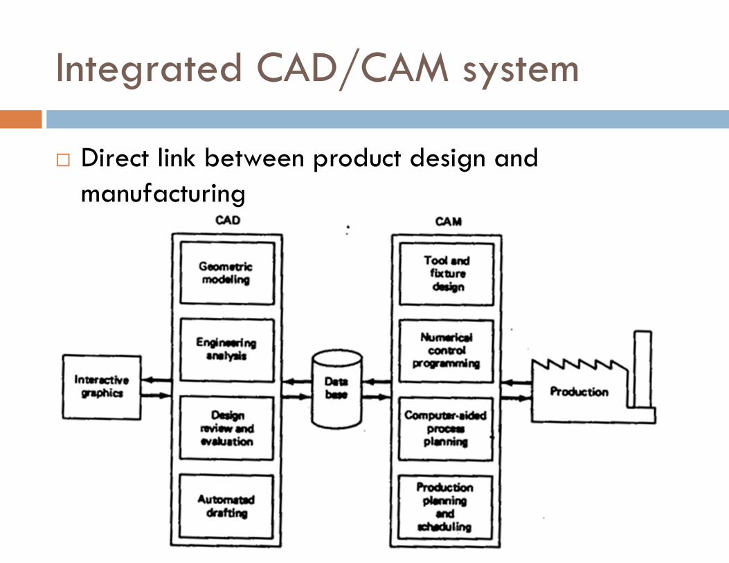
Integrated CAD/CAM system
� Direct link between product design and manufacturing
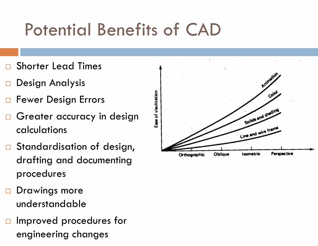
Potential Benefits of CAD
� Shorter Lead Times
� Design Analysis
� Fewer Design Errors
� Greater accuracy in design calculations
� Standardisation of design, drafting and documenting procedures
� Drawings more understandable
� Improved procedures for engineering changes
Potential Benefits of CAD
� Assignment to be submitted on Wed, 8th February
� 4 pages / 2 sheets
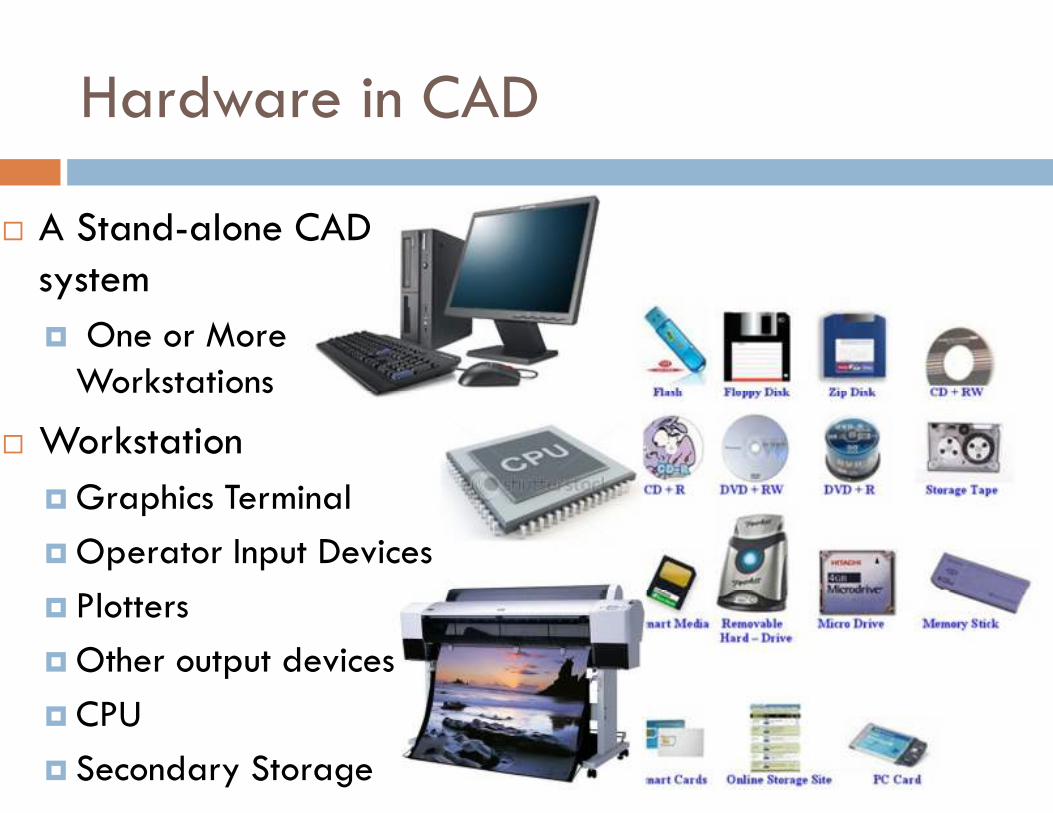
Hardware in CAD
� A Stand-alone CAD system
� One or More Workstations
� Workstation
� Graphics Terminal
� Operator Input Devices
� Plotters
� Other output devices
� CPU
� Secondary Storage
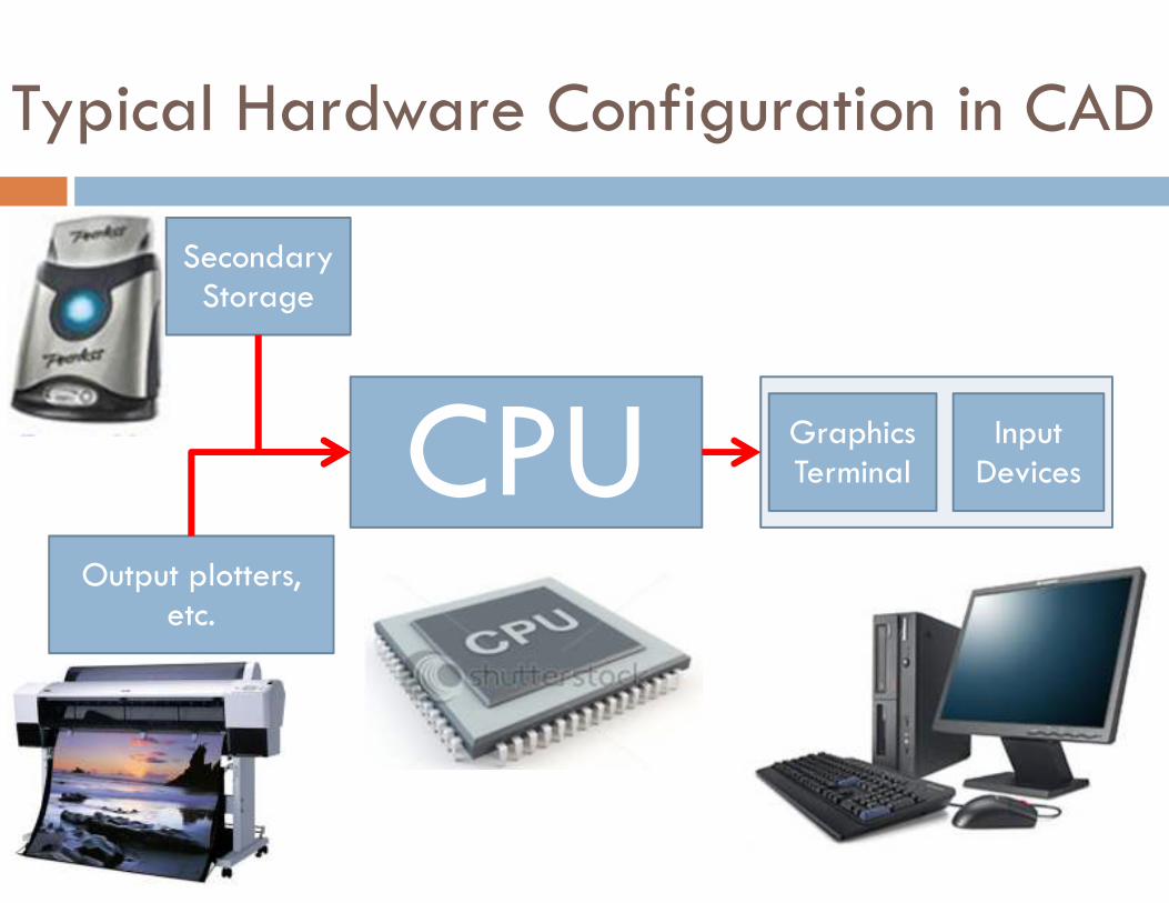
Typical Hardware Configuration in CAD
CPU Graphics Terminal
Input Devices
Secondary Storage
Output plotters, etc.
Design Workstation
� Five Functions
� Interface with CPU
� Generate Steady graphic image for the user
� Provide digital descriptions of the graphic image
� Translate computer commands to operating functions
� Facilitate communication between user and system
� All these five functions are achieved using
� ICG
� Interactive Computer Graphics
� ICG Workstation
� A graphics terminal
� Operator Input Device
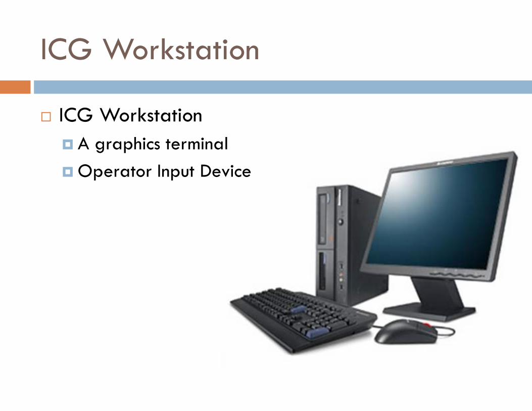
ICG Workstation
� ICG Workstation
� A graphics terminal
� Operator Input Device
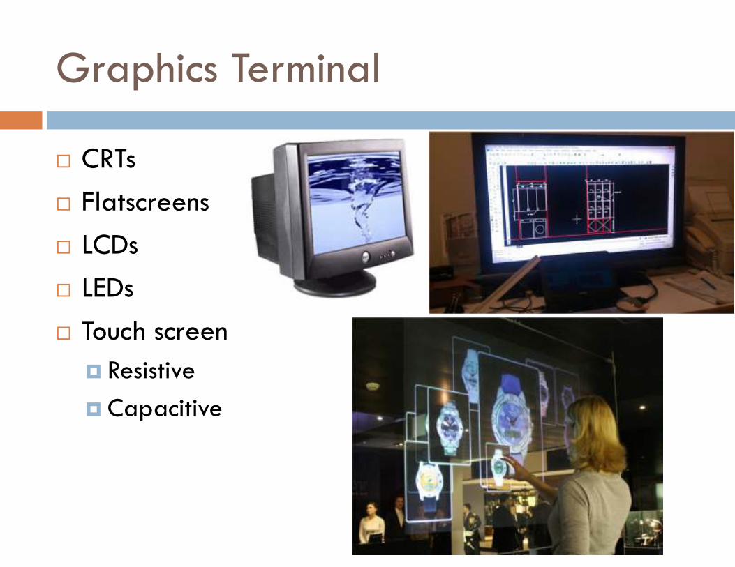
Graphics Terminal
� CRTs
� Flatscreens
� LCDs
� LEDs
� Touch screen
� Resistive
� Capacitive
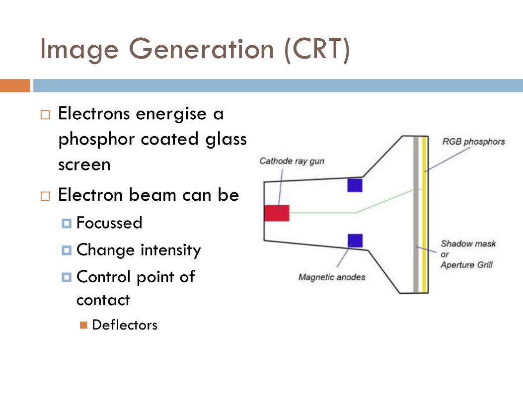
Image Generation (CRT)
� Electrons energise a phosphor coated glass screen
� Electron beam can be
� Focussed
� Change intensity
� Control point of contact
� Deflectors
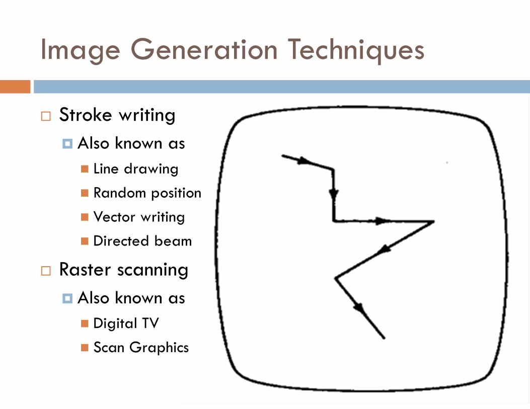
Image Generation Techniques
� Stroke writing
� Also known as
� Line drawing
� Random position
� Vector writing
� Directed beam
� Raster scanning
� Also known as
� Digital TV
� Scan Graphics
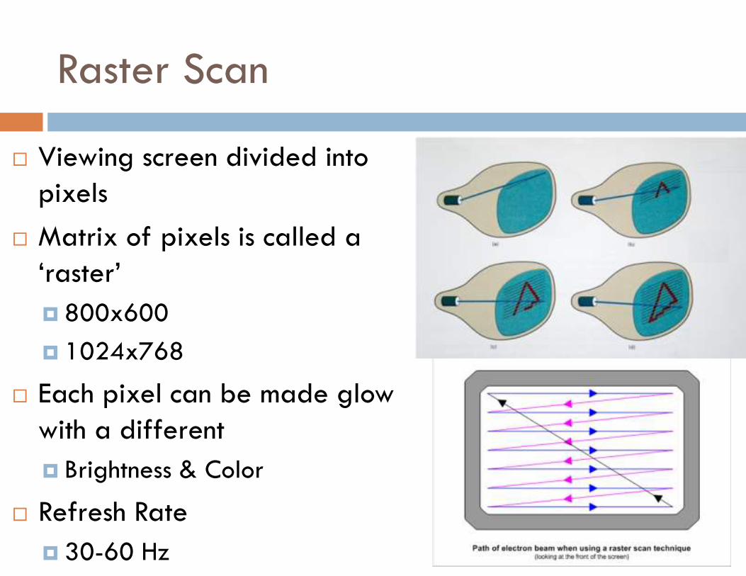
Raster Scan
� Viewing screen divided into pixels
� Matrix of pixels is called a ‘raster’
� 800x600
� 1024x768
� Each pixel can be made glow with a different
� Brightness & Color
� Refresh Rate
� 30-60 Hz
Graphics terminals for CAD
� Different types of screen based on
� Type of phophor coating
� Pixel Density
� B/W or Color
� Memory available for image generation
� Three types are
� Direct Beam Refresh
� Direct-View Storage Tube (DVST)
� Raster Scan (digital TV)
1. Direct Beam Refresh
� Uses Stroke-writing technique
� Phosphor screen can maintain brightness only for microseconds
� Screen must be refreshed many times per second
� Difficult to avoid flicker on dense screens
� Selective erasure and alteration of image readily accomplished
� Possible to provide animation using refresh tube
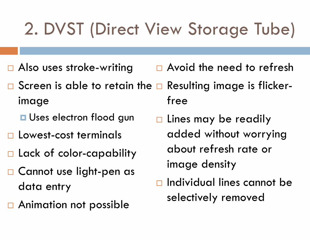
2. DVST (Direct View Storage Tube)
� Also uses stroke-writing
� Screen is able to retain the image
� Uses electron flood gun
� Lowest-cost terminals
� Lack of color-capability
� Cannot use light-pen as data entry
� Animation not possible
� Avoid the need to refresh
� Resulting image is flicker-free
� Lines may be readily added without worrying about refresh rate or image density
� Individual lines cannot be selectively removed
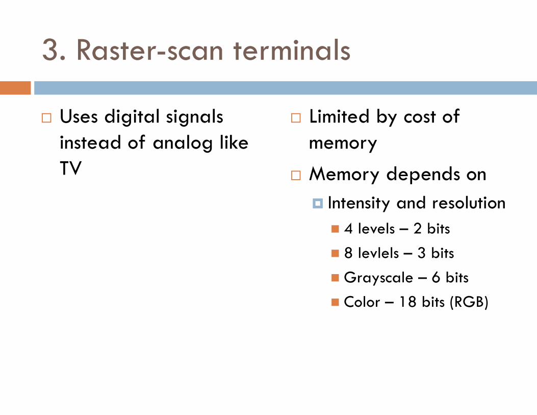
3. Raster-scan terminals
� Uses digital signals instead of analog like TV
� Limited by cost of memory
� Memory depends on
� Intensity and resolution
� 4 levels – 2 bits
� 8 levlels – 3 bits
� Grayscale – 6 bits
� Color – 18 bits (RGB)
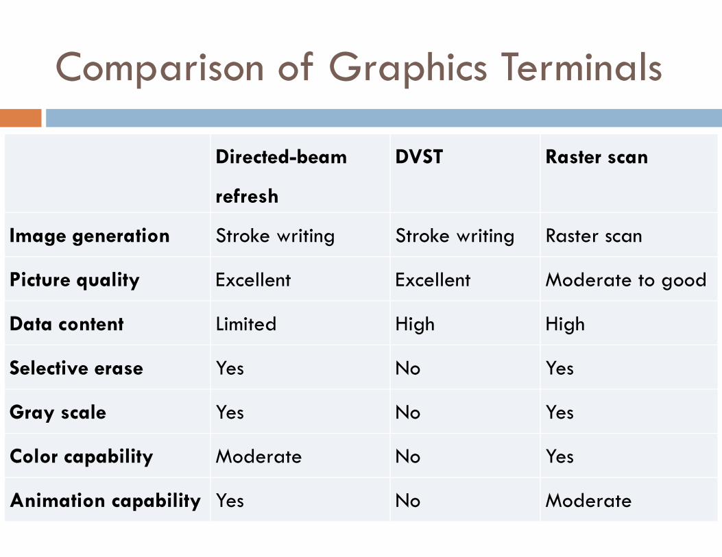
Comparison of Graphics Terminals
Directed-beam
refresh
DVST Raster scan
Image generation Stroke writing Stroke writing Raster scan
Picture quality Excellent Excellent Moderate to good
Data content Limited High High
Selective erase Yes No Yes
Gray scale Yes No Yes
Color capability Moderate No Yes
Animation capability Yes No Moderate
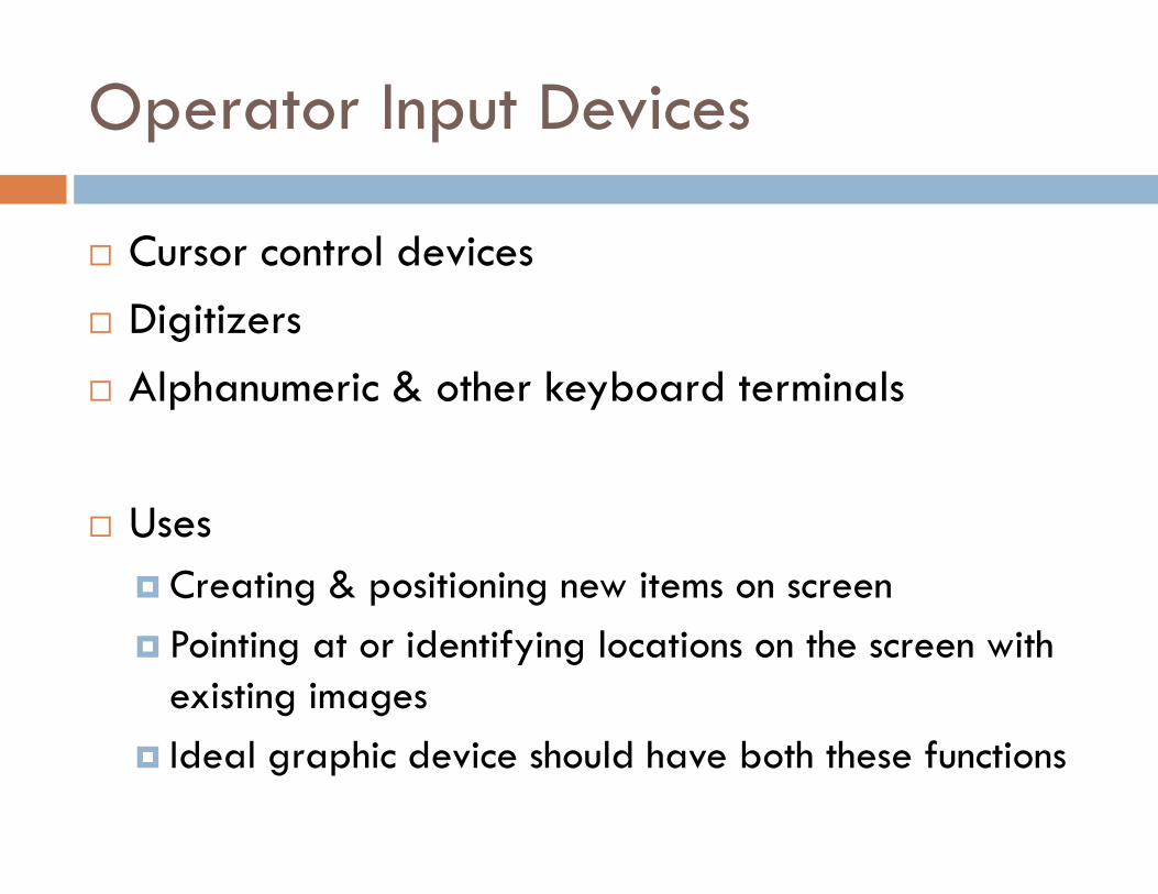
Operator Input Devices
� Cursor control devices
� Digitizers
� Alphanumeric & other keyboard terminals
� Uses
� Creating & positioning new items on screen
� Pointing at or identifying locations on the screen with existing images
� Ideal graphic device should have both these functions
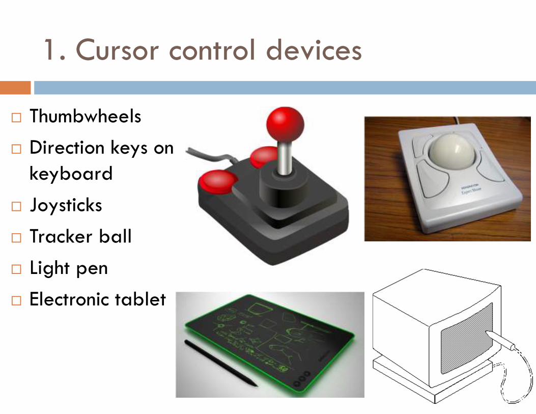
1. Cursor control devices
� Thumbwheels
� Direction keys on keyboard
� Joysticks
� Tracker ball
� Light pen
� Electronic tablet
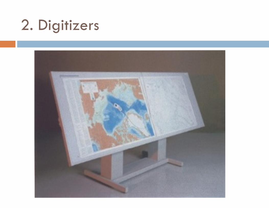
2. Digitizers
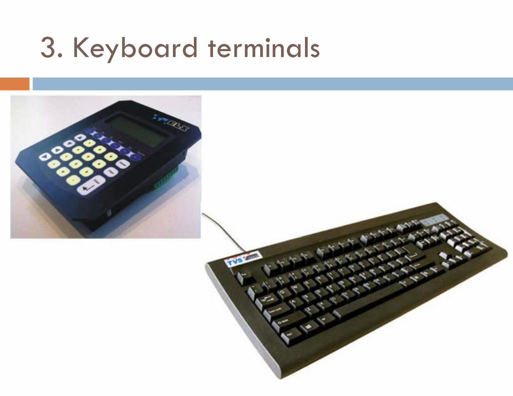
3. Keyboard terminals
Plotters & Output Devices
� Pen plotters
� Hard-copy units
� Electrostatic plotters
� Computer-output-microfilm (COM) units
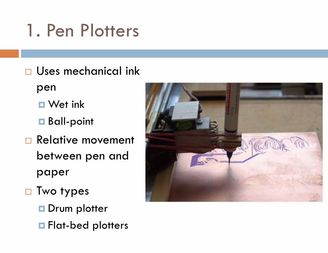
1. Pen Plotters
� Uses mechanical ink pen
� Wet ink
� Ball-point
� Relative movement between pen and paper
� Two types
� Drum plotter
� Flat-bed plotters
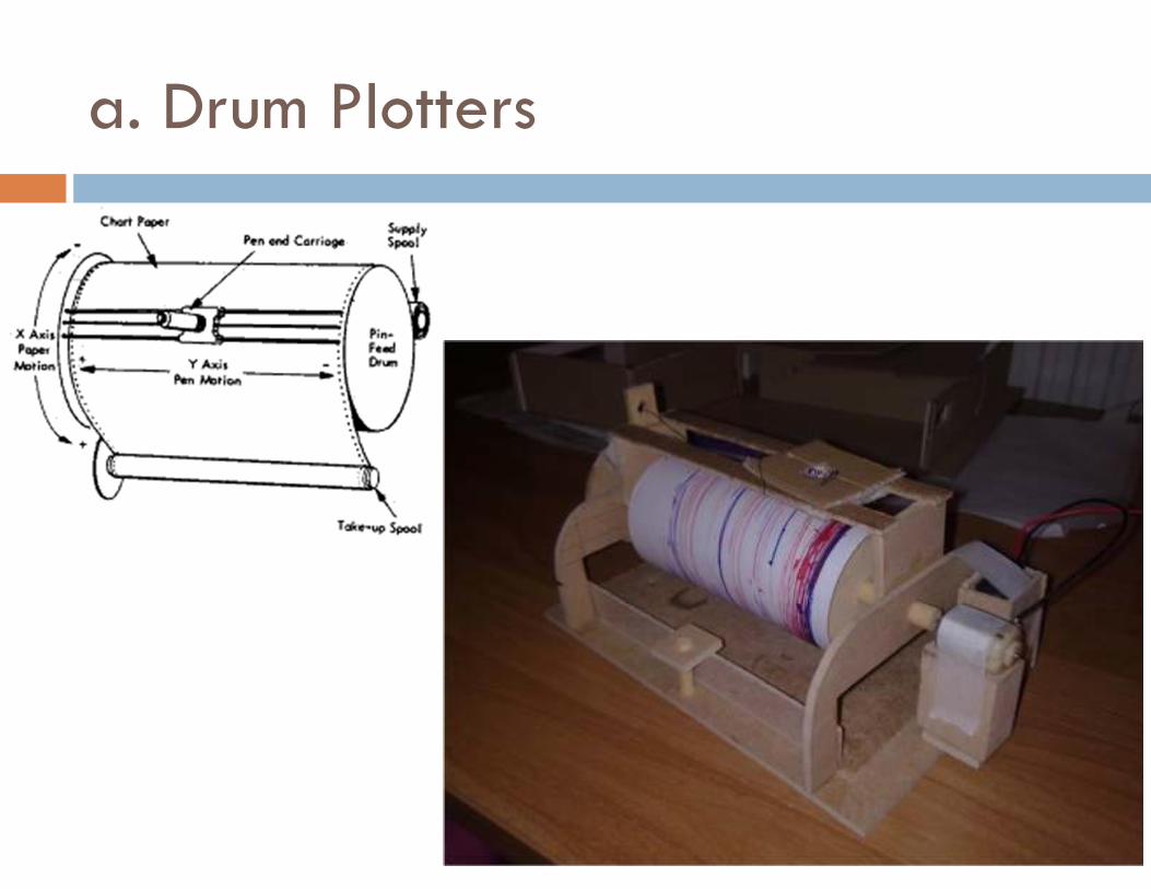
a. Drum Plotters
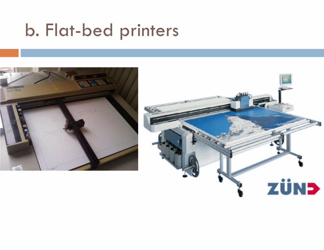
b. Flat-bed printers
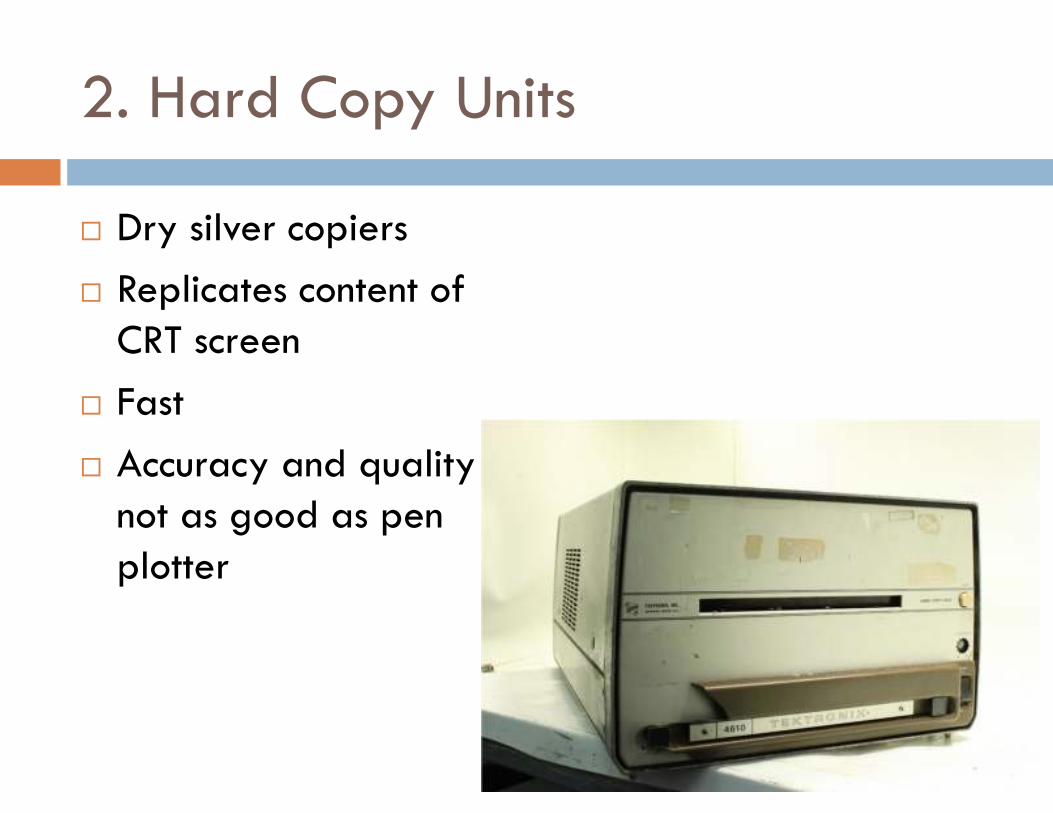
2. Hard Copy Units
� Dry silver copiers
� Replicates content of CRT screen
� Fast
� Accuracy and quality not as good as pen plotter
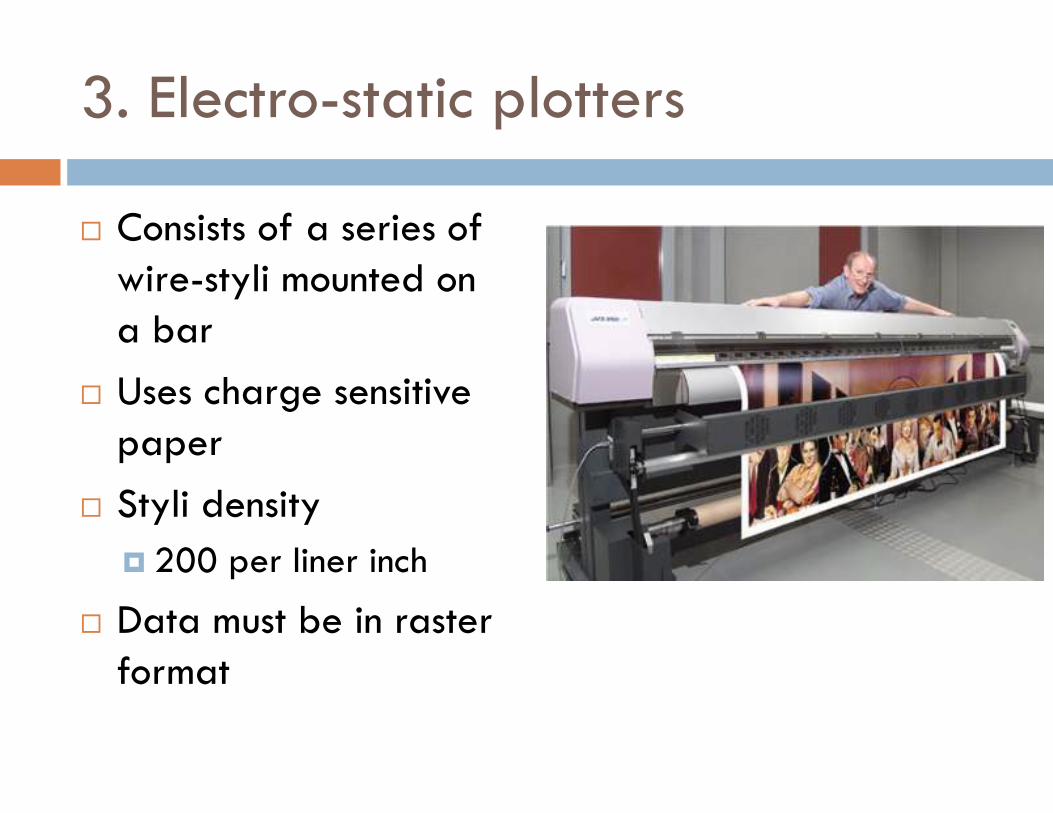
3. Electro-static plotters
� Consists of a series of wire-styli mounted on a bar
� Uses charge sensitive paper
� Styli density
� 200 per liner inch
� Data must be in raster format
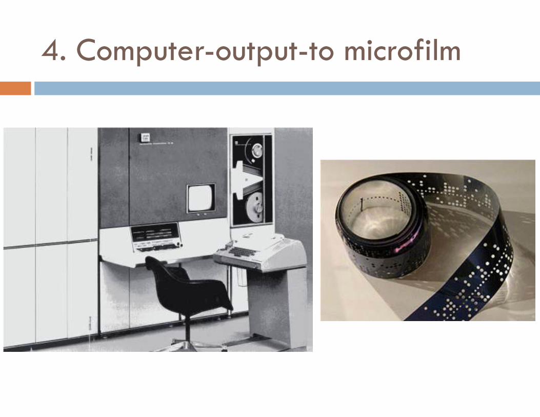
4. Computer-output-to microfilm
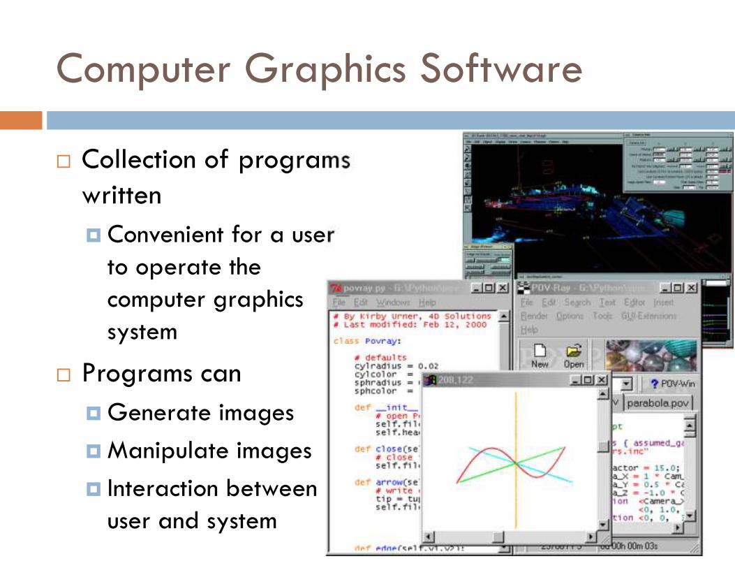
Computer Graphics Software
� Collection of programs written
� Convenient for a user to operate the computer graphics system
� Programs can
� Generate images
� Manipulate images
� Interaction between user and system
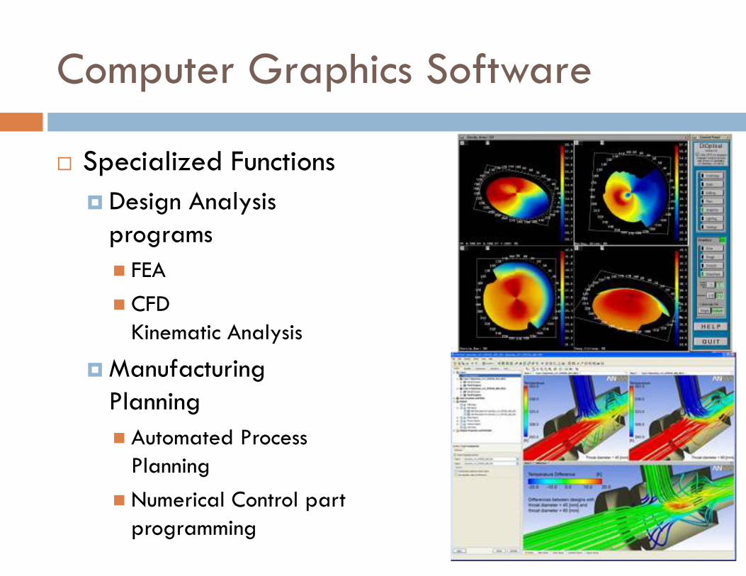
Computer Graphics Software
� Specialized Functions
� Design Analysis programs
� FEA
� CFD Kinematic Analysis
� Manufacturing Planning
� Automated Process Planning
� Numerical Control part programming
Ground rules for designing graphics software
� By Newman & Spoull
� Simplicity
� Easy to use
� Consistency
� Operate predictably to user
� Completeness
� No missing commands
� Robustness
� Tolerant to minor misuses by operator
� Performance
� Efficient. Within limits of hardware.
� Economy
Software configuration of a graphics system
� Activities
� Interact with graphics terminal
� Create / Alter images on screen
� Construct a model
� Using images on the screen
� Models are also called application models
� Save the model in memory
� Primary (RAM)
� Secondary (HDD / DVD / Flash Memory)
� User performs above actions
� In combination rather than sequentially
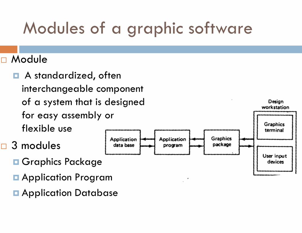
Modules of a graphic software
� Module
� A standardized, often interchangeable component of a system that is designed for easy assembly or flexible use
� 3 modules
� Graphics Package
� Application Program
� Application Database
Functions of a Graphics Package
� Generation of graphic elements
� Transformations
� Display control & Windowing functions
� Segmenting functions
� User input function
1. Generation of graphic elements
� Graphic element
� Dot
� Line
� Circle, etc….
� Also known as ‘primitives’
� Special hardware components for some basic elements
� Speeds up generation of these elements
� Primitive
� Sphere, Cube or Cylinder
� Used to generate more complex models
2. Transformations
� Applied to graphic elements to
� Modify image on screen
� Reposition item in database
� Transformations
� Scaling
� Reduction / Enlargement
� Translation
� Repositioning
� Rotation
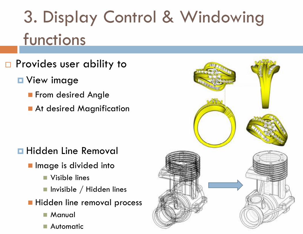
3. Display Control & Windowing functions
� Provides user ability to
� View image
� From desired Angle
� At desired Magnification
� Hidden Line Removal
� Image is divided into
� Visible lines
� Invisible / Hidden lines
� Hidden line removal process
� Manual
� Automatic
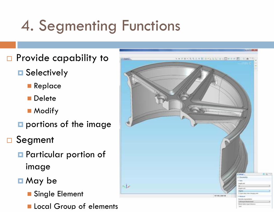
4. Segmenting Functions
� Provide capability to
� Selectively
� Replace
� Delete
� Modify
� portions of the image
� Segment
� Particular portion of image
� May be
� Single Element
� Local Group of elements
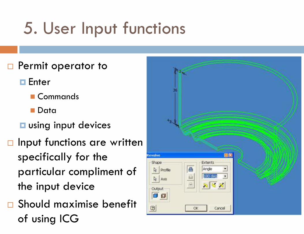
5. User Input functions
� Permit operator to
� Enter
� Commands
� Data
� using input devices
� Input functions are written specifically for the particular compliment of the input device
� Should maximise benefit of using ICG
Constructing the geometry
� Use of Graphic elements
� Defining graphic elements
� Editing the geometry
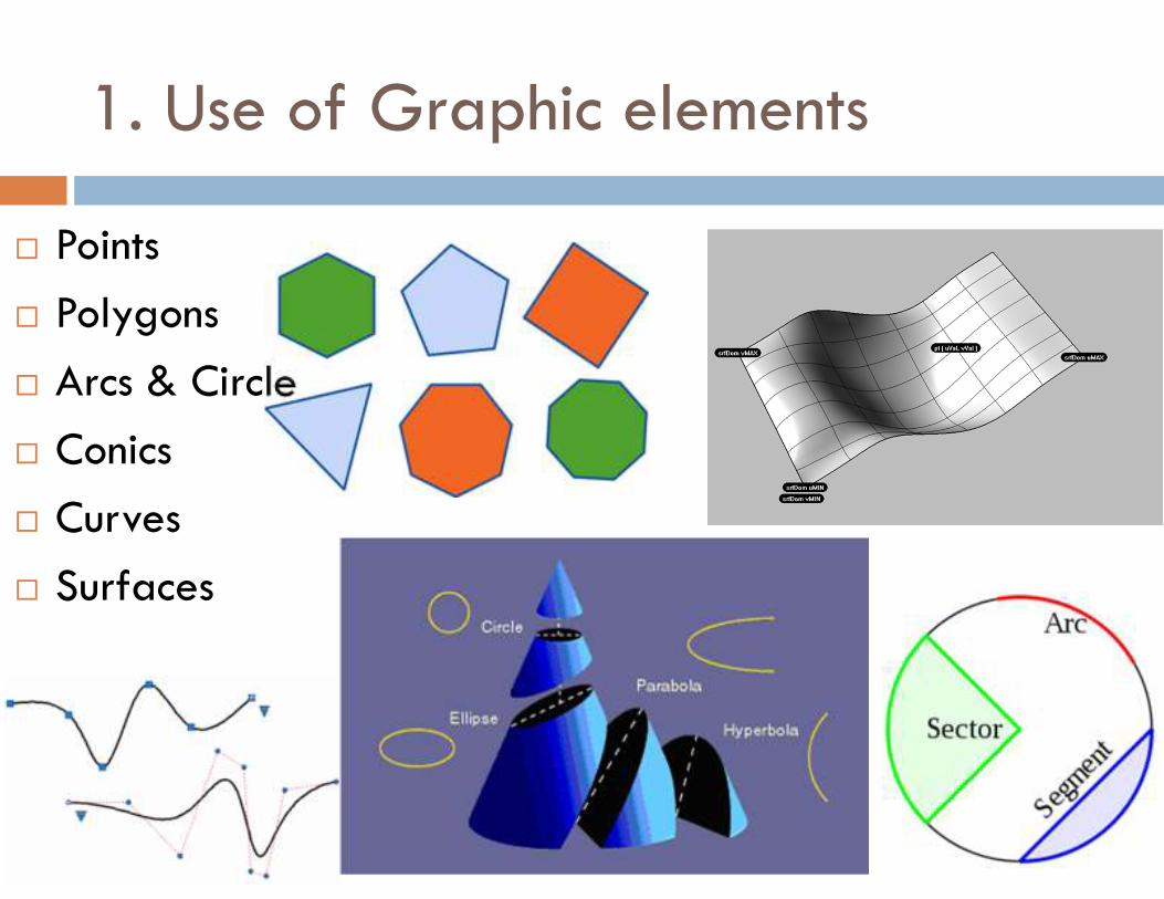
1. Use of Graphic elements
� Points
� Polygons
� Arcs & Circle
� Conics
� Curves
� Surfaces
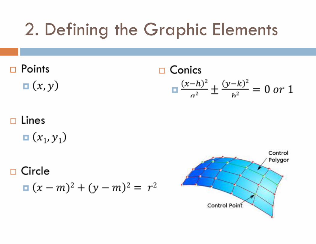
2. Defining the Graphic Elements
�
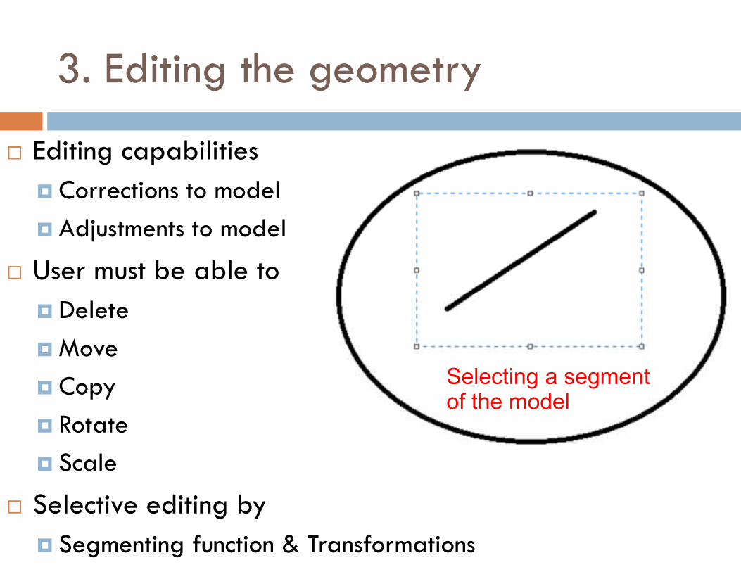
3. Editing the geometry
� Editing capabilities
� Corrections to model
� Adjustments to model
� User must be able to
� Delete
� Move
� Copy
� Rotate
� Scale
� Selective editing by
� Segmenting function & Transformations
Selecting a segment of the model
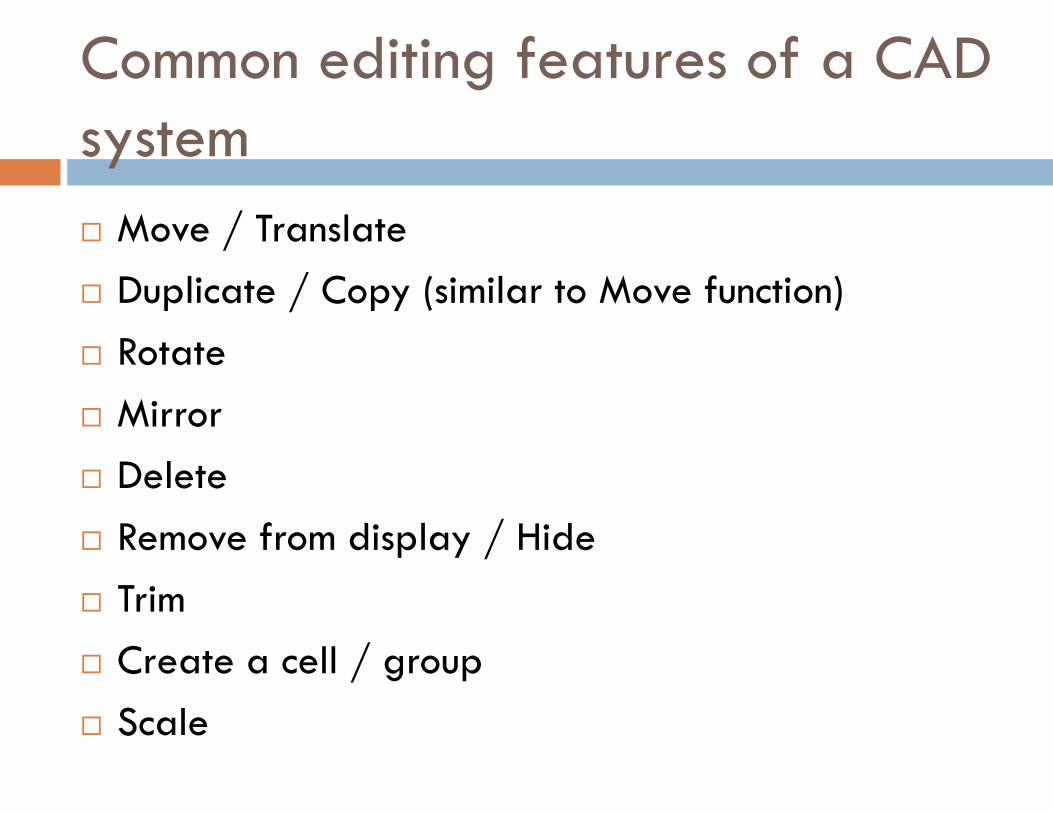
Common editing features of a CAD system
� Move / Translate
� Duplicate / Copy (similar to Move function)
� Rotate
� Mirror
� Delete
� Remove from display / Hide
� Trim
� Create a cell / group
� Scale
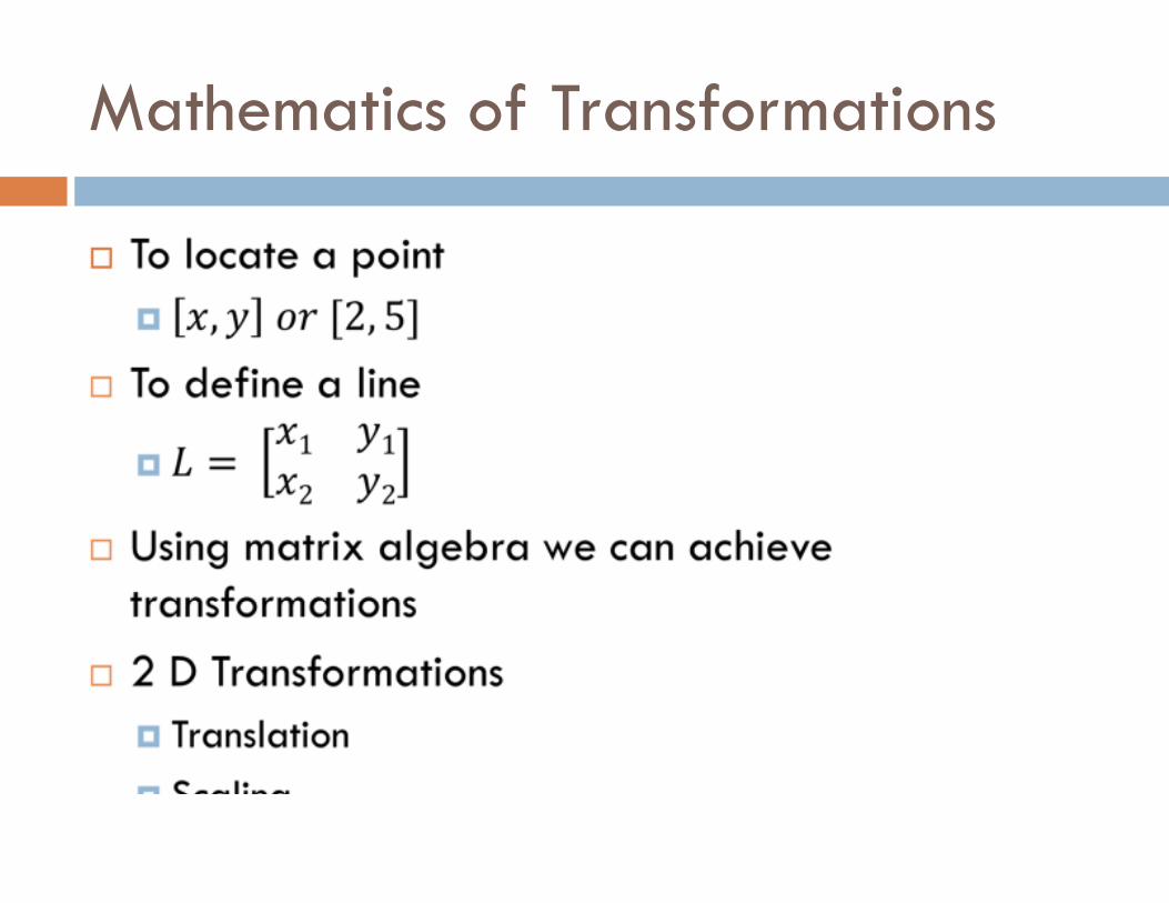
Mathematics of Transformations
�
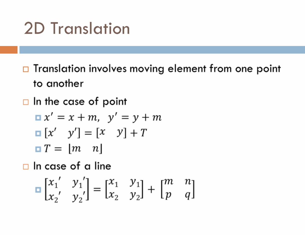
2D Translation
�
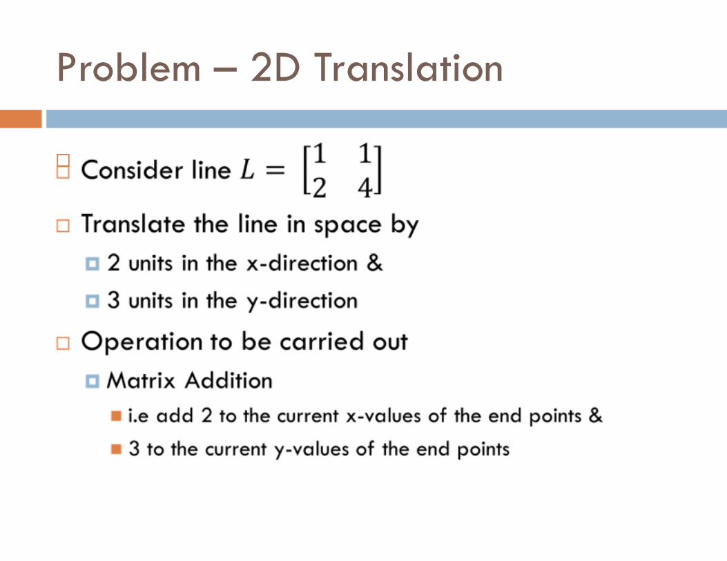
Problem – 2D Translation
�
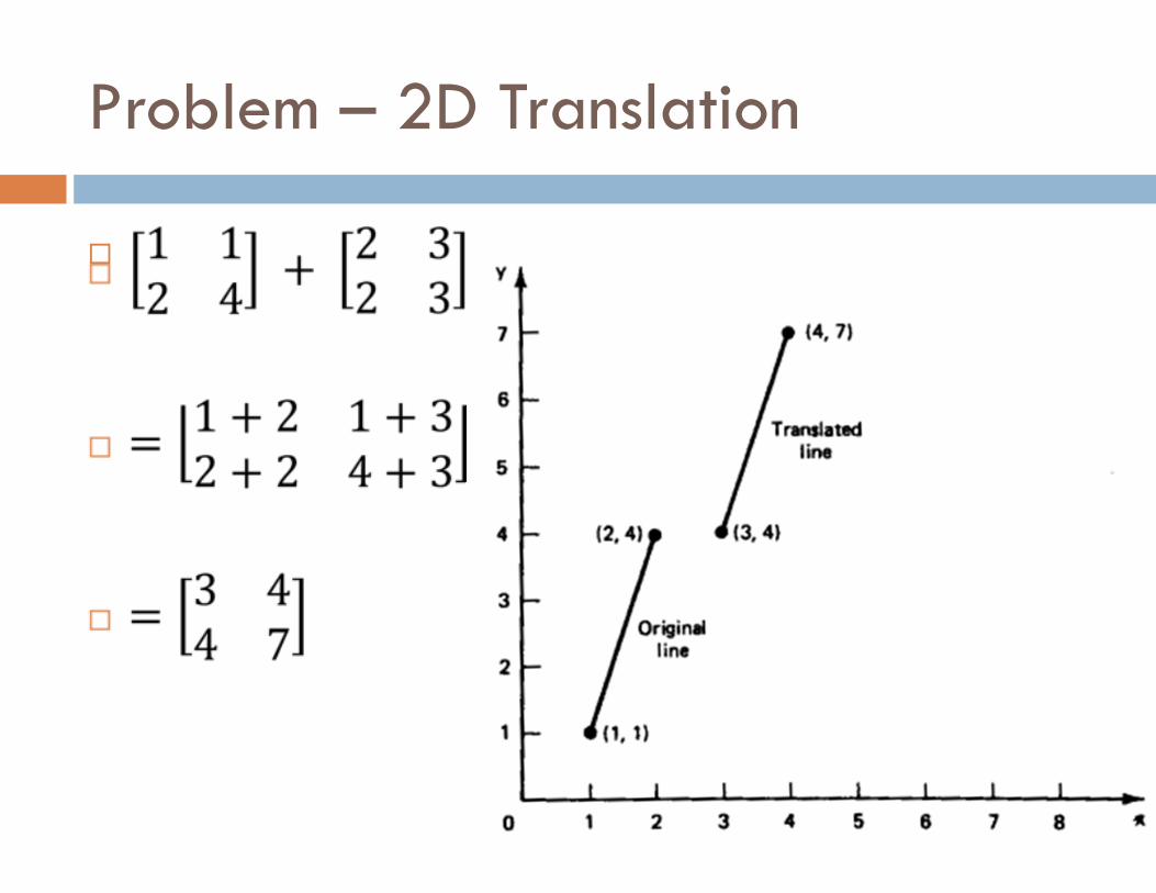
Problem – 2D Translation
�
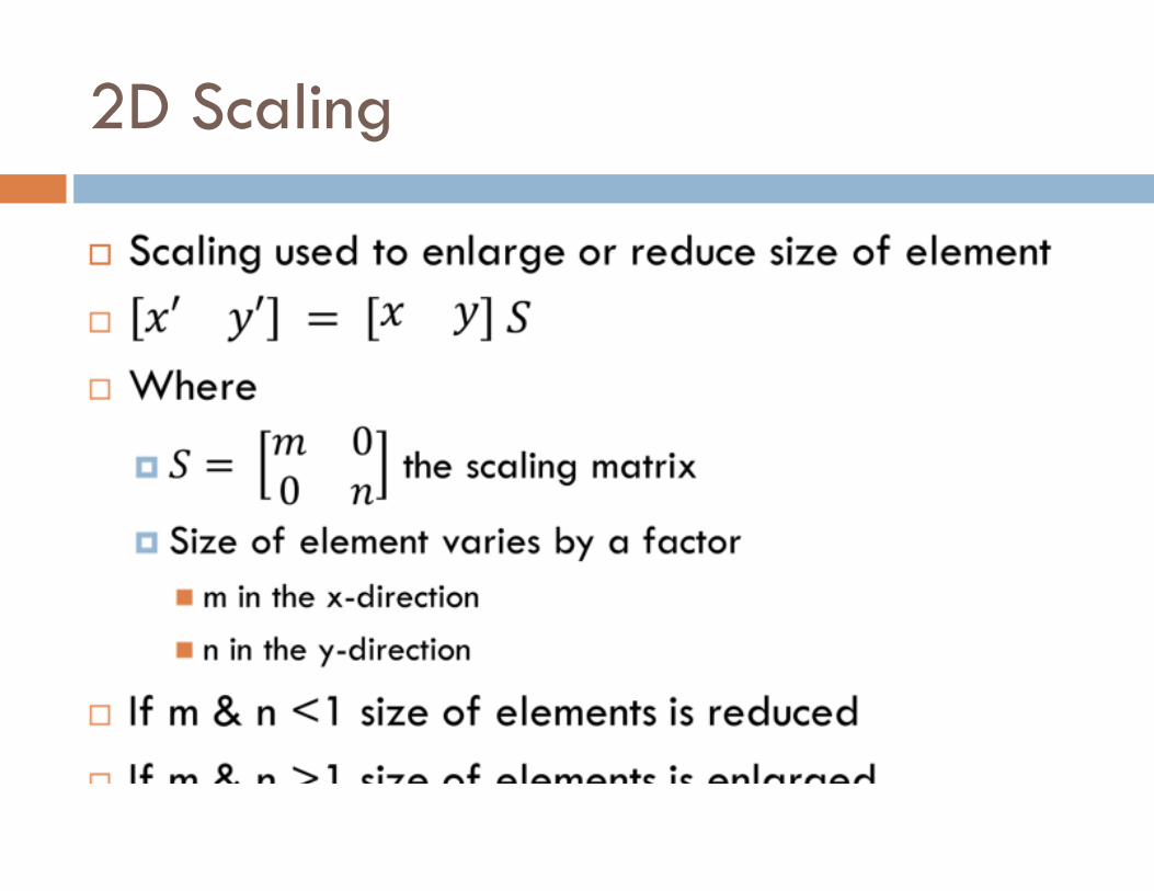
2D Scaling
�
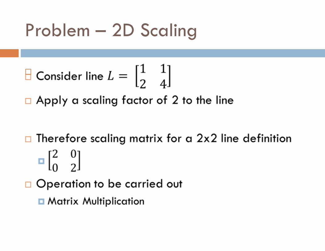
Problem – 2D Scaling
�
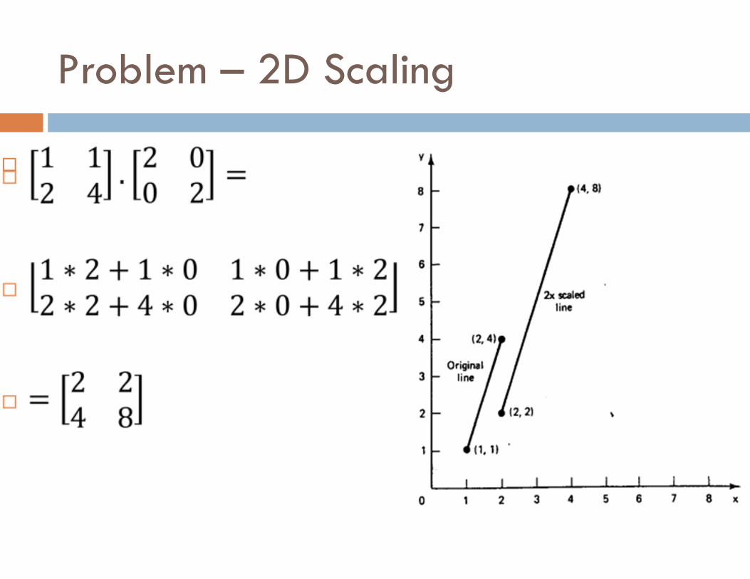
Problem – 2D Scaling
�
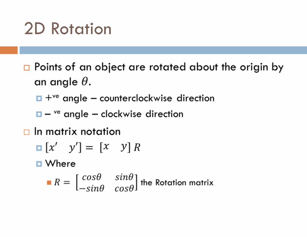
2D Rotation
�
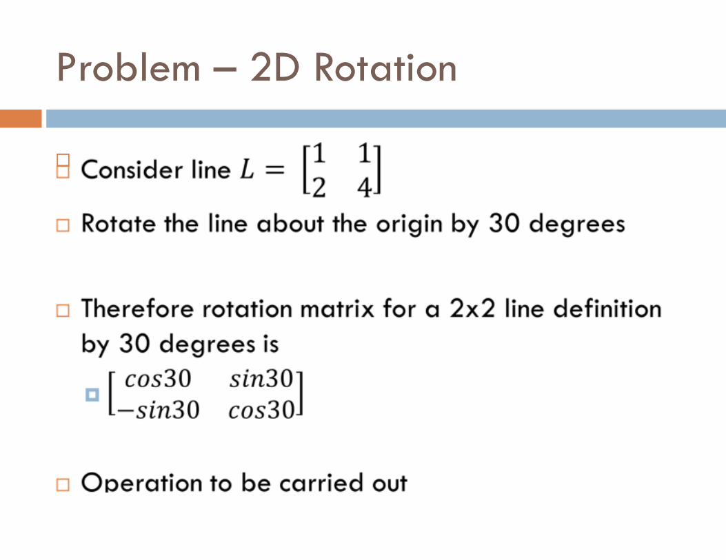
Problem – 2D Rotation
�
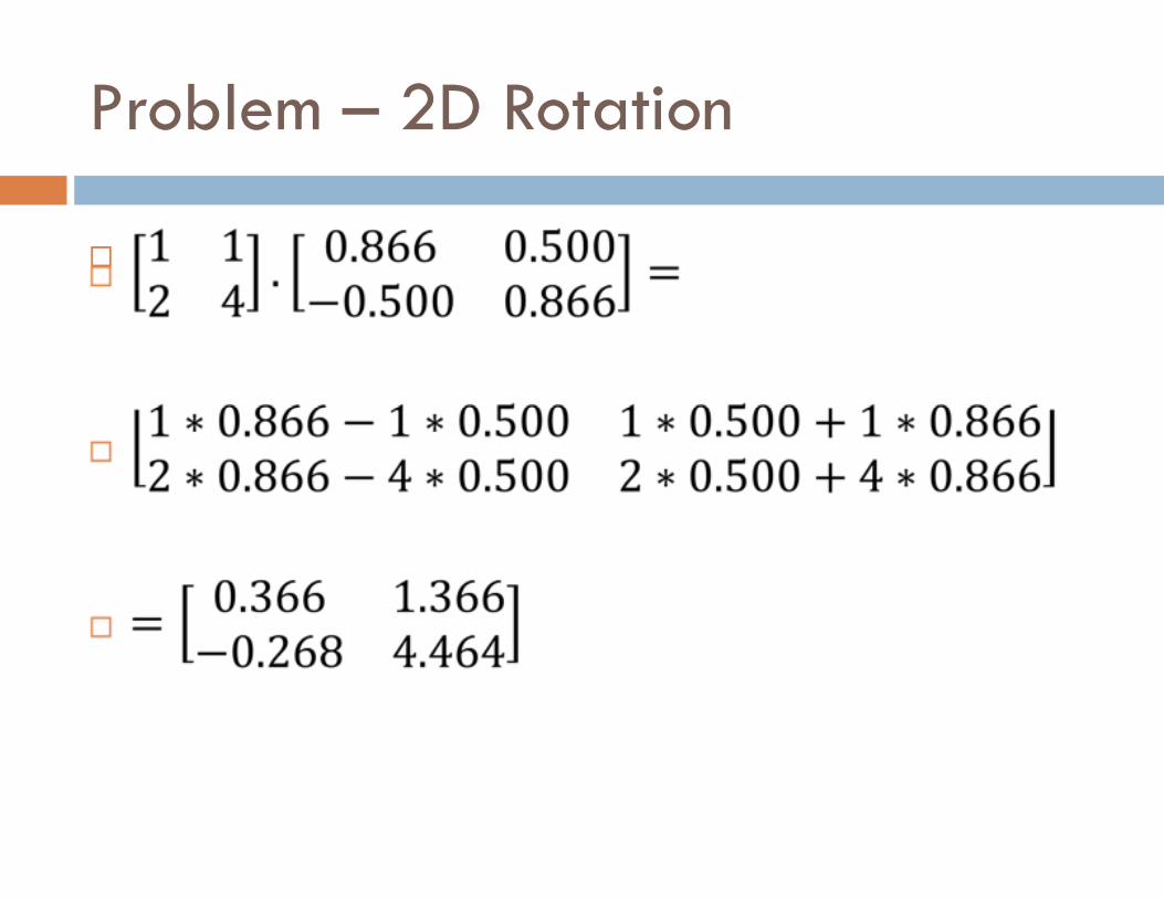
Problem – 2D Rotation
�
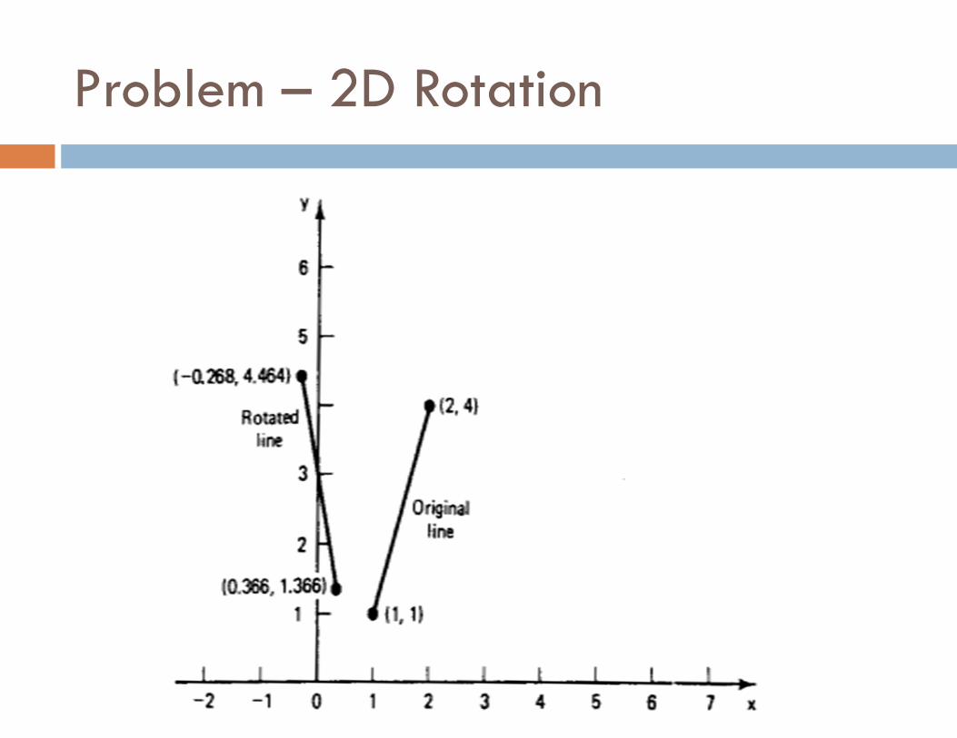
Problem – 2D Rotation
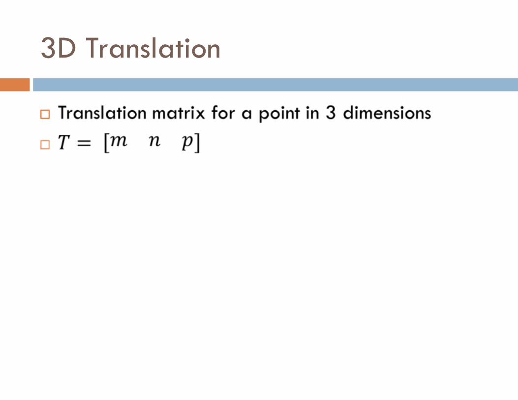
3D Translation
�
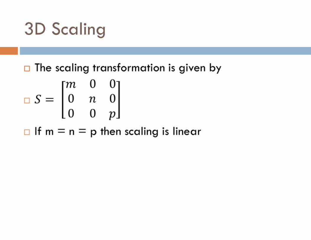
3D Scaling
�
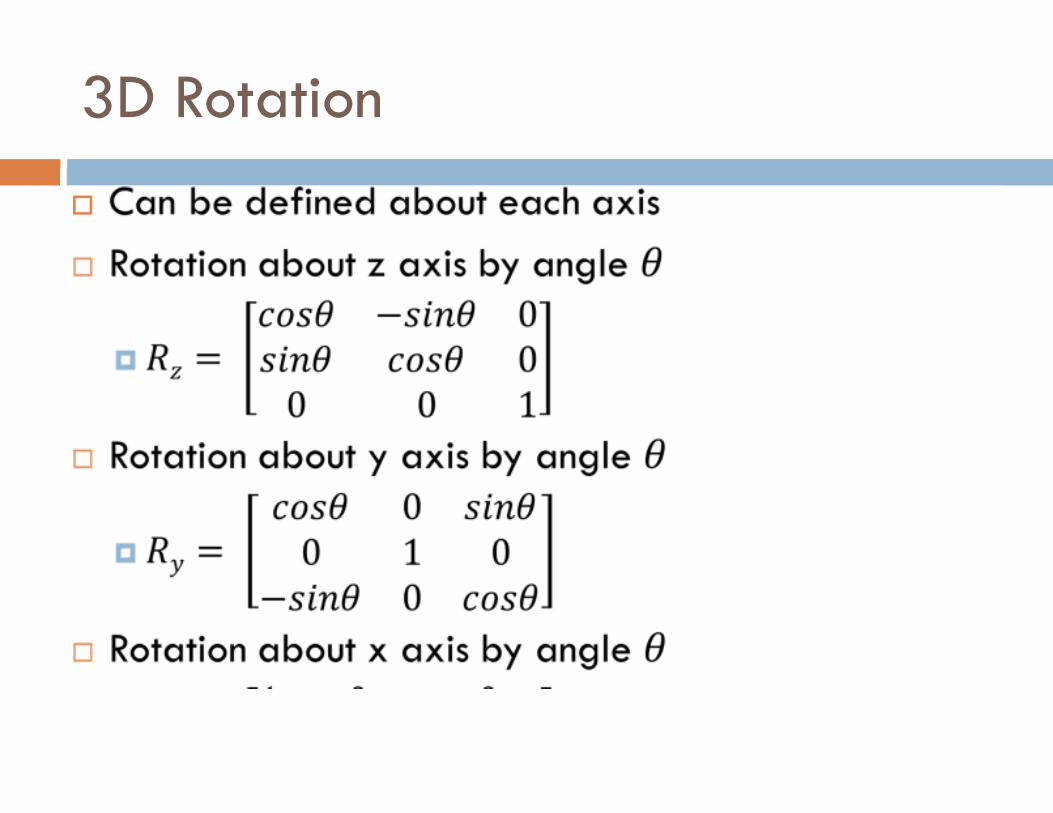
3D Rotation
�
Concatenation
� Multiple transformations can be combined as a sequence of transformations
� Known as concatenated transformations
� E.g.
� Rotation of element
� Magnifying the element
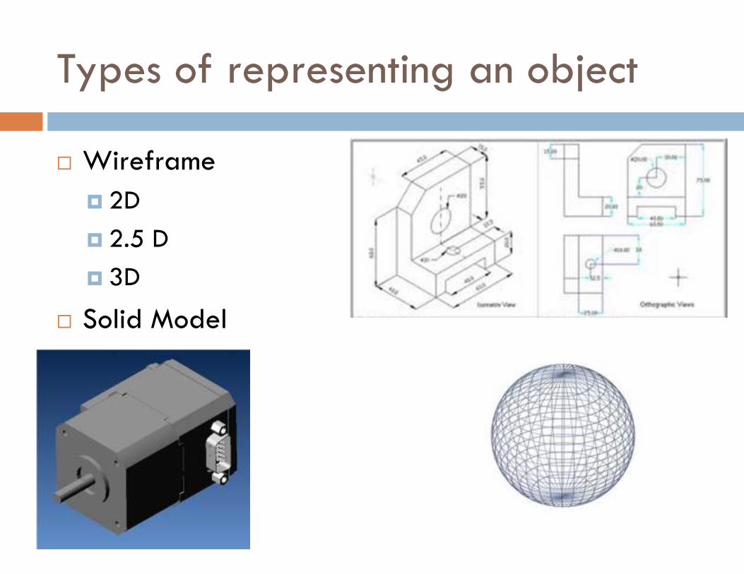
Types of representing an object
� Wireframe
� 2D
� 2.5 D
� 3D
� Solid Model
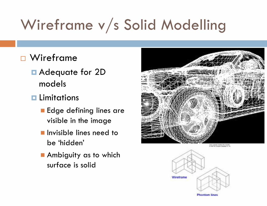
Wireframe v/s Solid Modelling
� Wireframe
� Adequate for 2D models
� Limitations
� Edge defining lines are visible in the image
� Invisible lines need to be ‘hidden’
� Ambiguity as to which surface is solid
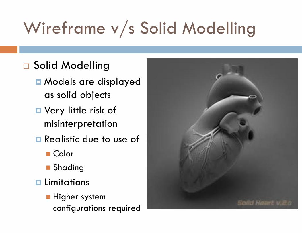
Wireframe v/s Solid Modelling
� Solid Modelling
� Models are displayed as solid objects
� Very little risk of misinterpretation
� Realistic due to use of
� Color
� Shading
� Limitations
� Higher system configurations required
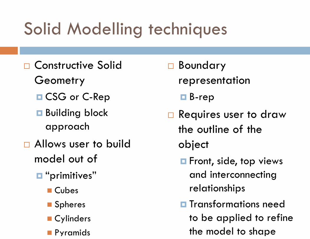
Solid Modelling techniques
� Constructive Solid Geometry
� CSG or C-Rep
� Building block approach
� Allows user to build model out of
� “primitives”
� Cubes
� Spheres
� Cylinders
� Pyramids
� Boundary representation
� B-rep
� Requires user to draw the outline of the object
� Front, side, top views and interconnecting relationships
� Transformations need to be applied to refine the model to shape
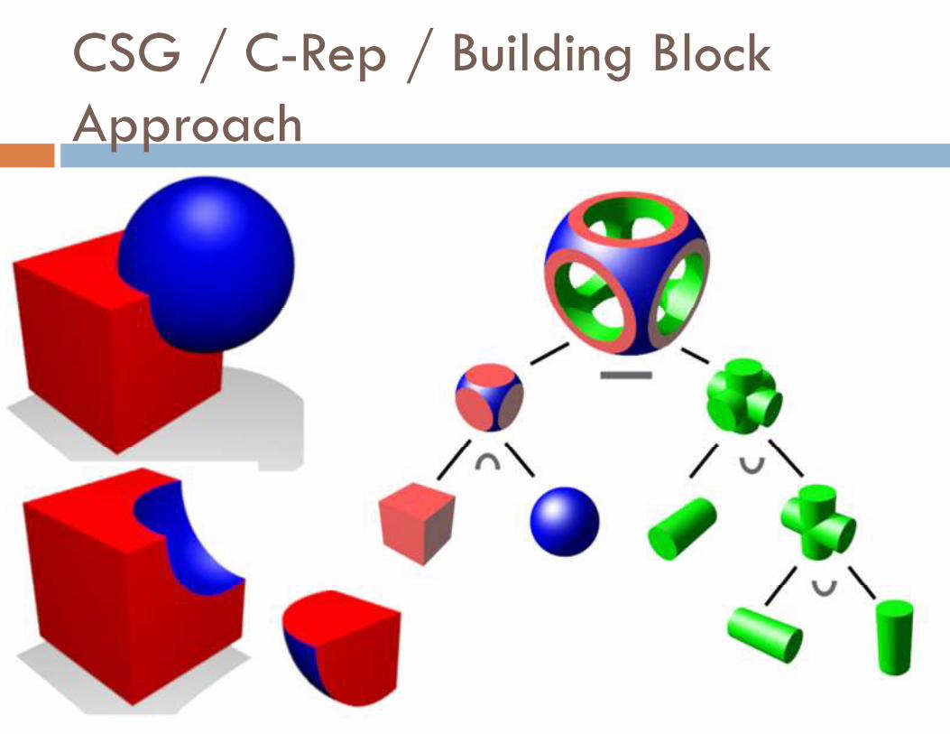
CSG / C-Rep / Building Block Approach
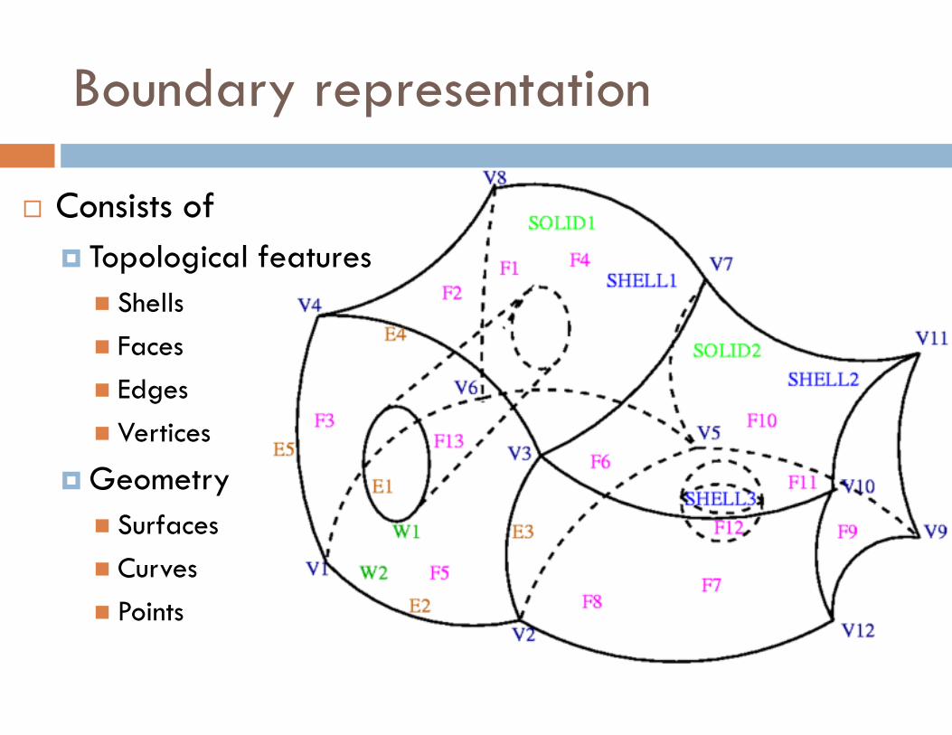
Boundary representation
� Consists of
� Topological features
� Shells
� Faces
� Edges
� Vertices
� Geometry
� Surfaces
� Curves
� Points
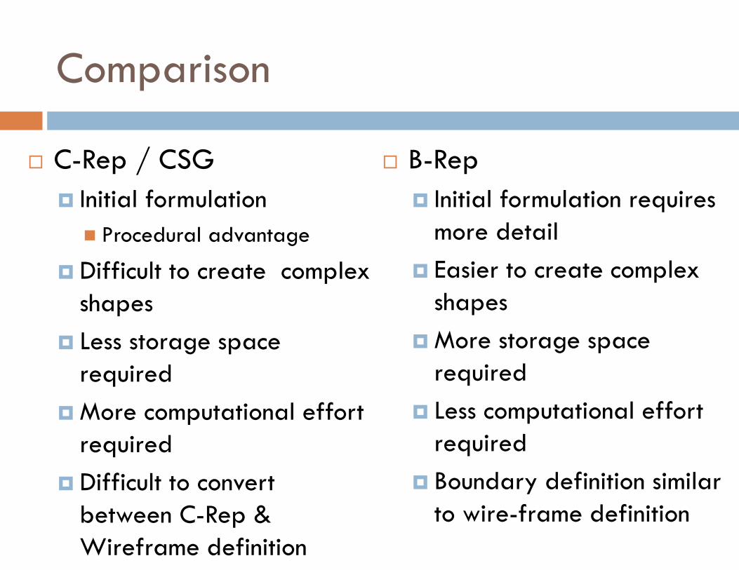
Comparison
� C-Rep / CSG
� Initial formulation
� Procedural advantage
� Difficult to create complex shapes
� Less storage space required
� More computational effort required
� Difficult to convert between C-Rep & Wireframe definition
� B-Rep
� Initial formulation requires more detail
� Easier to create complex shapes
� More storage space required
� Less computational effort required
� Boundary definition similar to wire-frame definition
Vector Generation
� Process of turning on pixels
� Two VG Algorithm
� DDA (Digital Differential Analysers) Algorithm
� Bresenham’s Algorithm
DDA Algorithm
� Based on dy, dx
� Floating point arithmetic
� Hence slower
� More accurate
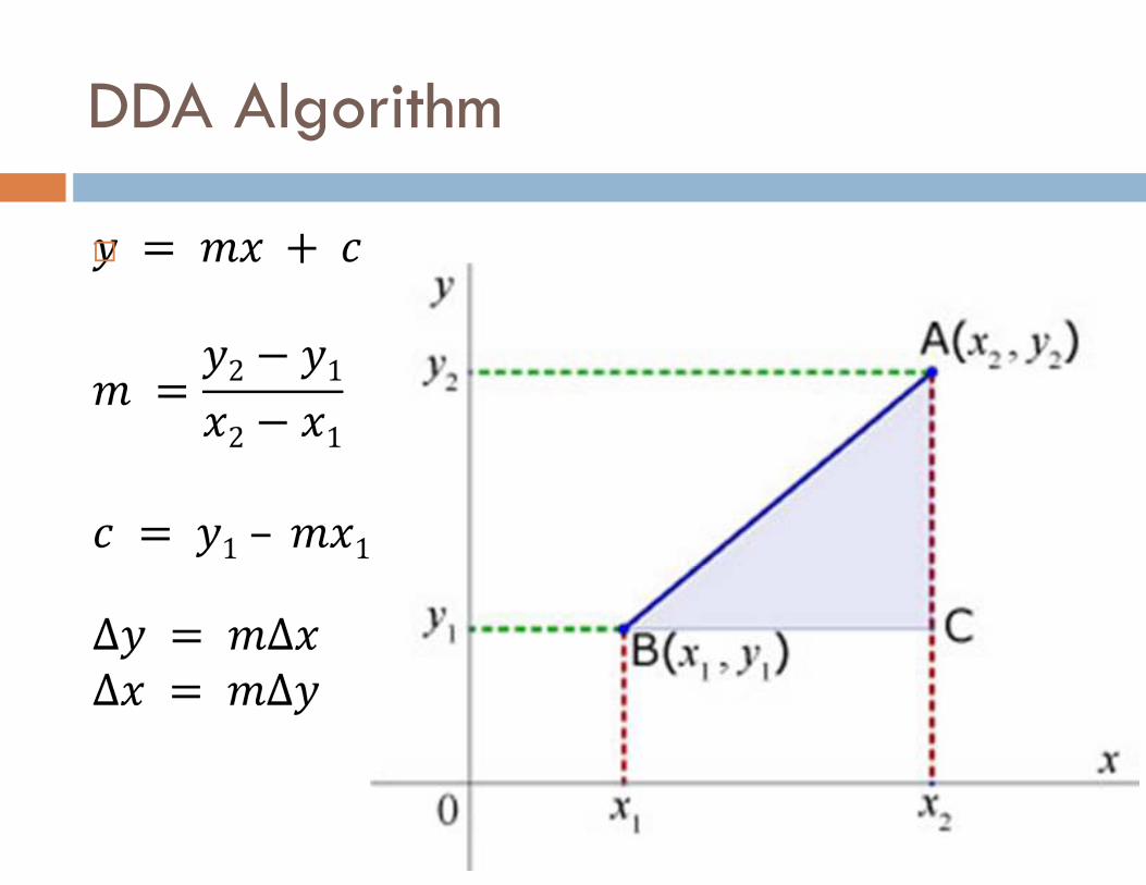
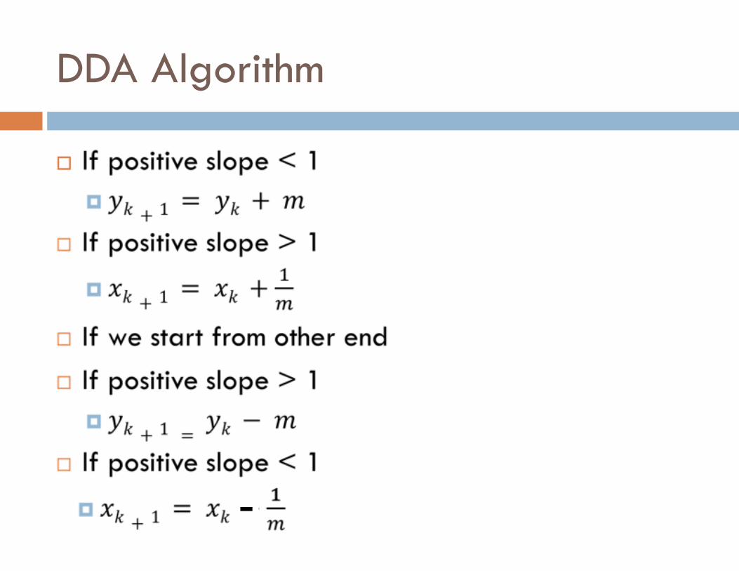
DDA Algorithm
�
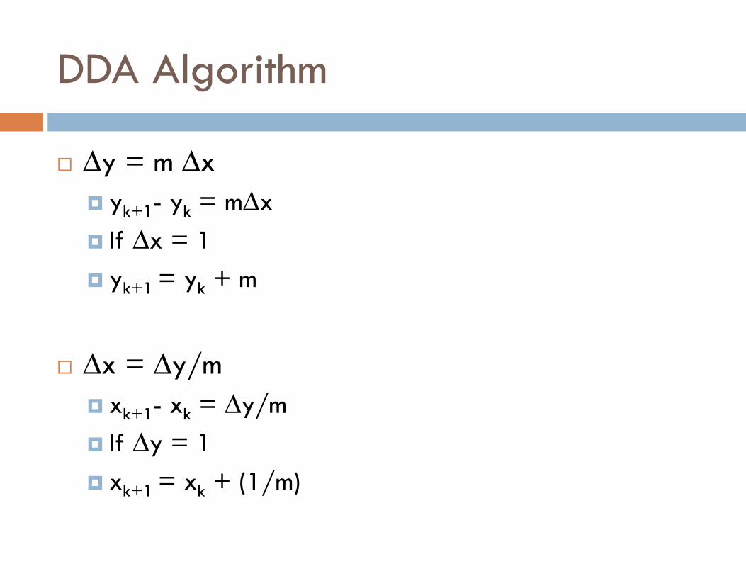
DDA Algorithm
� ∆y = m ∆x
� yk+1- yk = m∆x
� If ∆x = 1
� yk+1 = yk + m
� ∆x = ∆y/m
� xk+1- xk = ∆y/m
� If ∆y = 1
� xk+1 = xk + (1/m)
�
DDA Algorithm
-
Bresenham’s Line Drawing Algorithm
Bresenham’s Line Drawing Algorithm
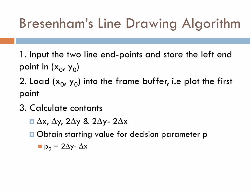
1. Input the two line end-points and store the left end point in (x0, y0)
2. Load (x0, y0) into the frame buffer, i.e plot the first point
3. Calculate contants
� ∆x, ∆y, 2∆y & 2∆y- 2∆x
� Obtain starting value for decision parameter p
� p0 = 2∆y- ∆x
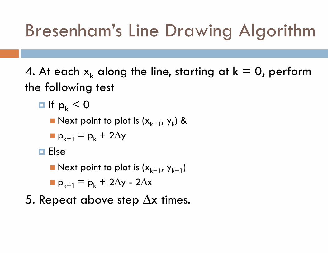
4. At each xk along the line, starting at k = 0, perform the following test
� If pk < 0
� Next point to plot is (xk+1, yk) &
� pk+1 = pk + 2∆y
� Else
� Next point to plot is (xk+1, yk+1)
� pk+1 = pk + 2∆y - 2∆x
5. Repeat above step ∆x times.
Bresenham’s Line Drawing Algorithm
Bresenham’s Line Drawing Algorithm
� Example
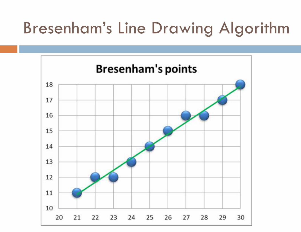
� Digitize the line with endpoints (20,10) & (30,18) with slope 0.8
Bresenham’s Line Drawing Algorithm
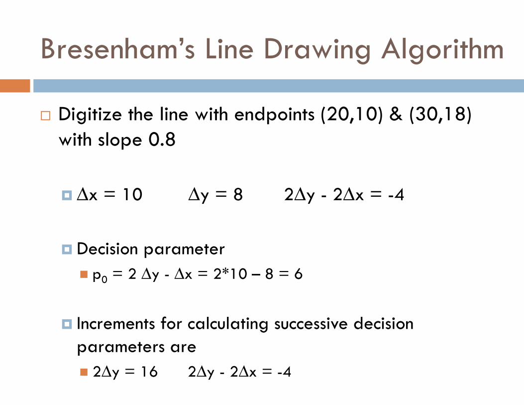
� Digitize the line with endpoints (20,10) & (30,18) with slope 0.8
� ∆x = 10 ∆y = 8 2∆y - 2∆x = -4
� Decision parameter
� p0 = 2 ∆y - ∆x = 2*10 – 8 = 6
� Increments for calculating successive decision parameters are
� 2∆y = 16 2∆y - 2∆x = -4
Bresenham’s Line Drawing Algorithm
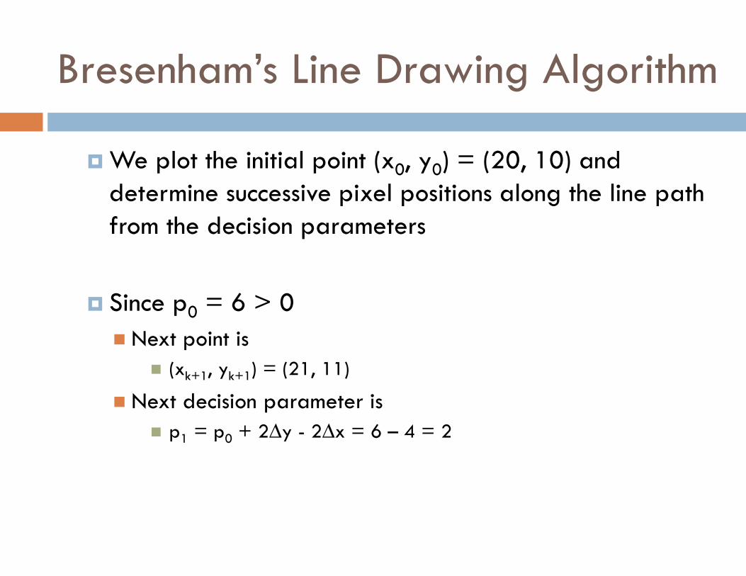
� We plot the initial point (x0, y0) = (20, 10) and determine successive pixel positions along the line path from the decision parameters
� Since p0 = 6 > 0
� Next point is
� (xk+1, yk+1) = (21, 11)
� Next decision parameter is
� p1 = p0 + 2∆y - 2∆x = 6 – 4 = 2
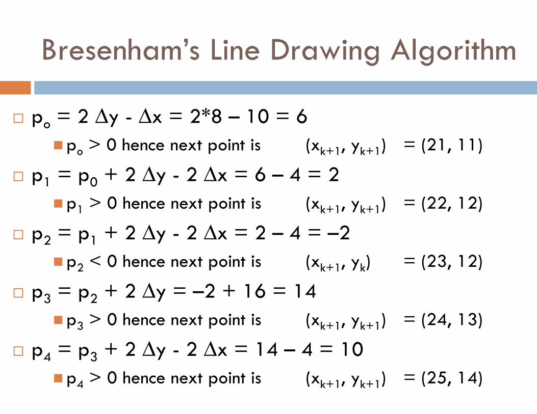
� po = 2 ∆y - ∆x = 2*8 – 10 = 6
�po > 0 hence next point is (xk+1, yk+1) = (21, 11)
� p1 = p0 + 2 ∆y - 2 ∆x = 6 – 4 = 2
�p1 > 0 hence next point is (xk+1, yk+1) = (22, 12)
� p2 = p1 + 2 ∆y - 2 ∆x = 2 – 4 = –2
�p2 < 0 hence next point is (xk+1, yk) = (23, 12)
� p3 = p2 + 2 ∆y = –2 + 16 = 14
�p3 > 0 hence next point is (xk+1, yk+1) = (24, 13)
� p4 = p3 + 2 ∆y - 2 ∆x = 14 – 4 = 10
�p4 > 0 hence next point is (xk+1, yk+1) = (25, 14)
Bresenham’s Line Drawing Algorithm
Bresenham’s Line Drawing Algorithm
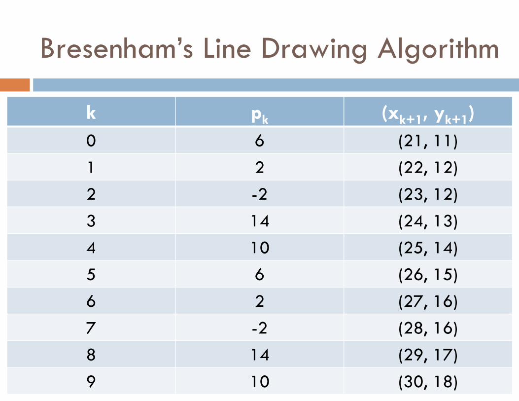
k pk (xk+1, yk+1)
0 6 (21, 11)
1 2 (22, 12)
2 -2 (23, 12)
3 14 (24, 13)
4 10 (25, 14)
5 6 (26, 15)
6 2 (27, 16)
7 -2 (28, 16)
8 14 (29, 17)
9 10 (30, 18)

Bresenham’s Line Drawing Algorithm
Bresenham’s Circle Drawing Algorithm
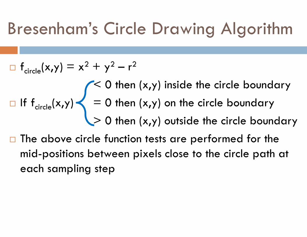
� fcircle(x,y) = x2 + y2 – r2
< 0 then (x,y) inside the circle boundary
� If fcircle(x,y) = 0 then (x,y) on the circle boundary
> 0 then (x,y) outside the circle boundary
� The above circle function tests are performed for the mid-positions between pixels close to the circle path at each sampling step
Bresenham’s Circle Drawing Algorithm
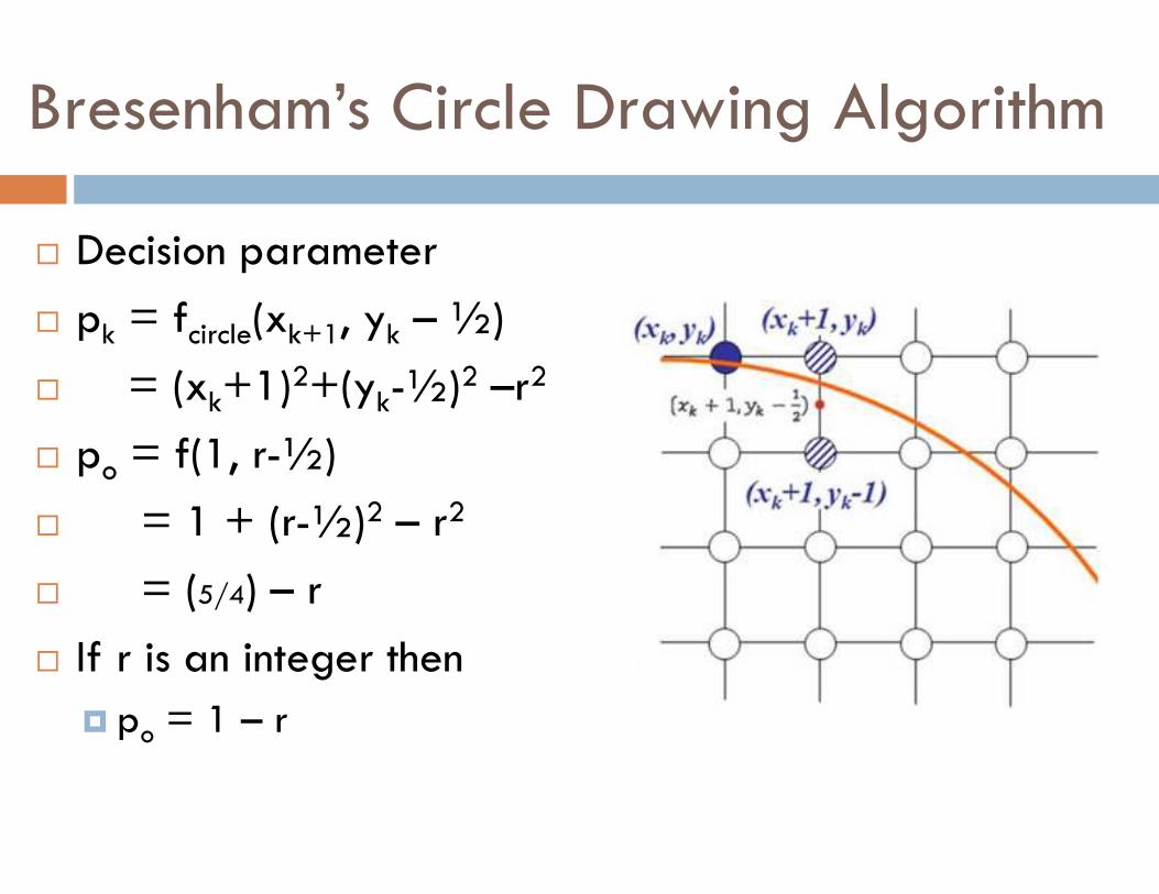
� Decision parameter
� pk = fcircle(xk+1, yk – ½)
� = (xk+1)2+(yk-½)2 –r2
� po = f(1, r-½)
� = 1 + (r-½)2 – r2
� = (5/4) – r
� If r is an integer then
� po = 1 – r
Bresenham’s Circle Drawing Algorithm
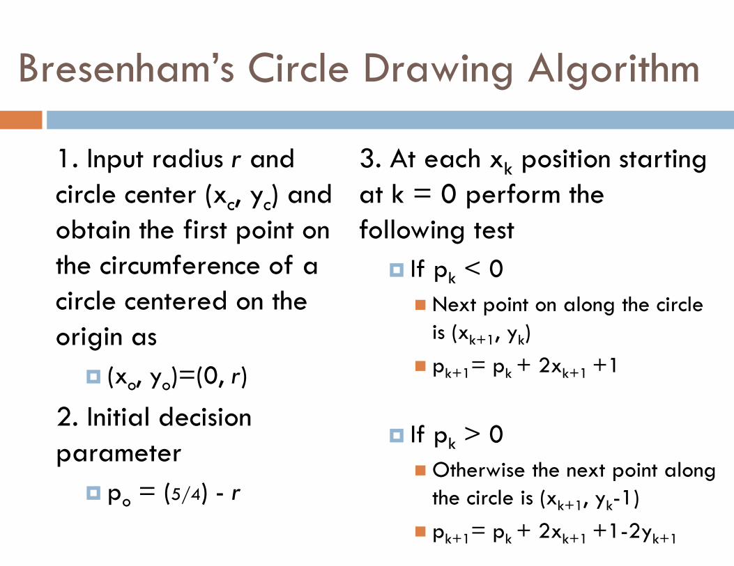
1. Input radius r and circle center (xc, yc) and obtain the first point on the circumference of a circle centered on the origin as
� (xo, yo)=(0, r)
2. Initial decision parameter
� po = (5/4) - r
3. At each xk position starting at k = 0 perform the following test
� If pk < 0
� Next point on along the circle is (xk+1, yk)
� pk+1= pk + 2xk+1 +1
� If pk > 0
� Otherwise the next point along the circle is (xk+1, yk-1)
� pk+1= pk + 2xk+1 +1-2yk+1
Bresenham’s Circle Drawing Algorithm
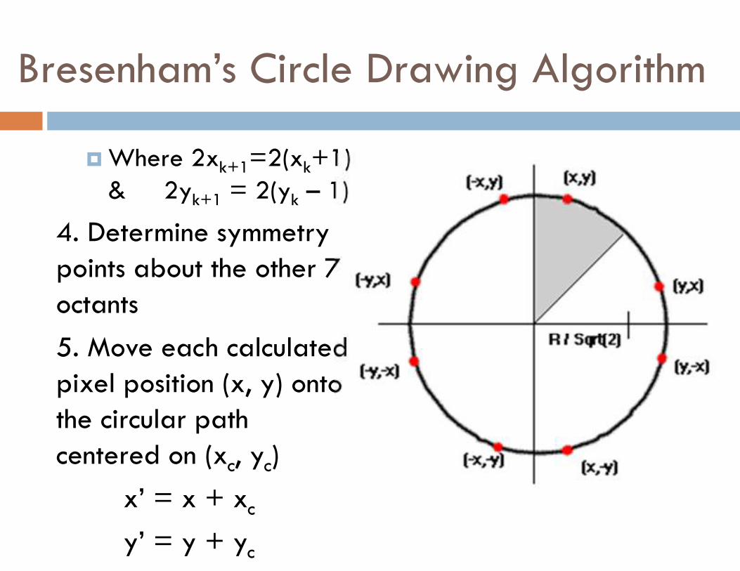
� Where 2xk+1=2(xk+1) & 2yk+1 = 2(yk – 1)
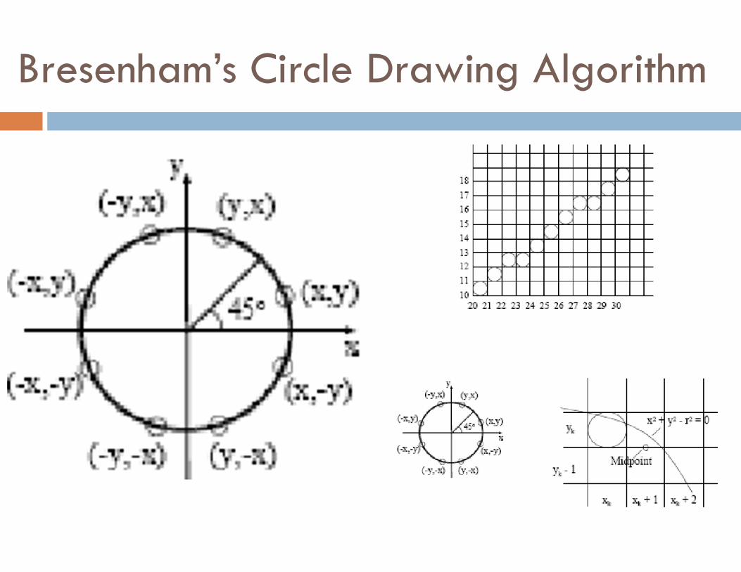
4. Determine symmetry points about the other 7 octants
5. Move each calculated pixel position (x, y) onto the circular path centered on (xc, yc)
x’ = x + xc
y’ = y + yc
Bresenham’s Circle Drawing Algorithm
Bresenham’s Circle Drawing Algorithm
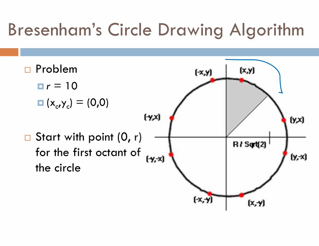
� Problem
� r = 10
� (xc,yc) = (0,0)
� Start with point (0, r) for the first octant of the circle
Bresenham’s Circle Drawing Algorithm
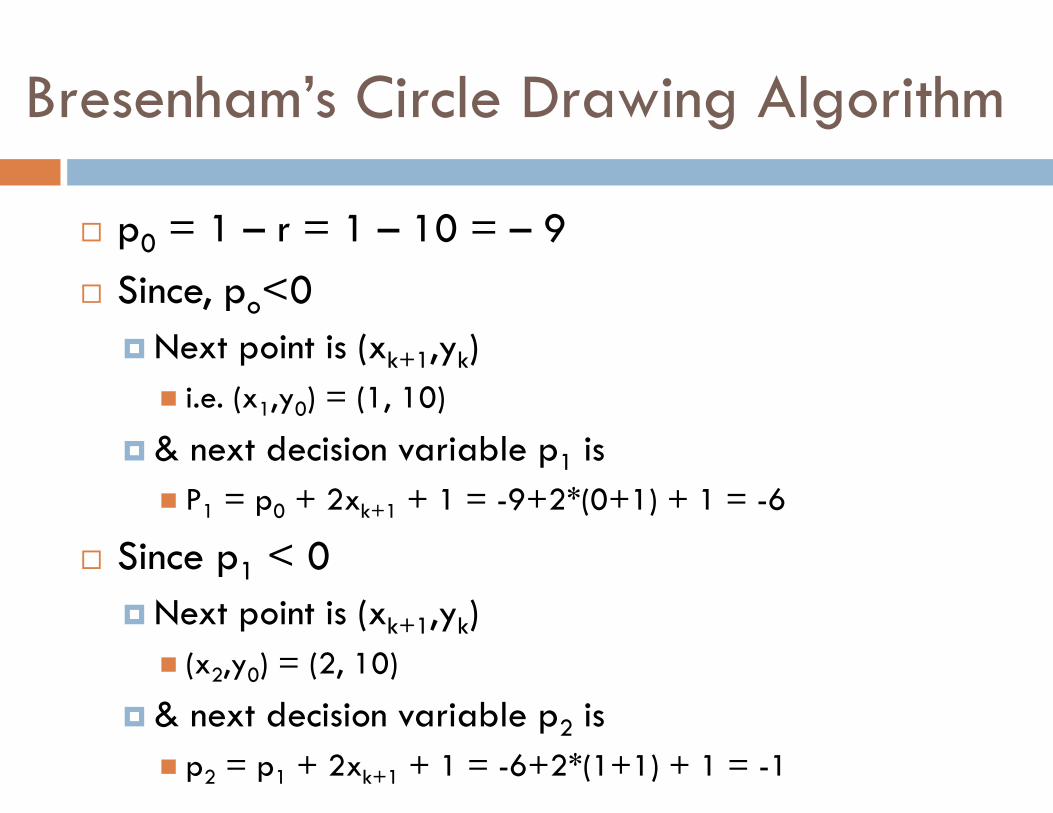
� p0 = 1 – r = 1 – 10 = – 9
� Since, po<0
� Next point is (xk+1,yk)
� i.e. (x1,y0) = (1, 10)
� & next decision variable p1 is
� P1 = p0 + 2xk+1 + 1 = -9+2*(0+1) + 1 = -6
� Since p1 < 0
� Next point is (xk+1,yk)
� (x2,y0) = (2, 10)
� & next decision variable p2 is
� p2 = p1 + 2xk+1 + 1 = -6+2*(1+1) + 1 = -1
Bresenham’s Circle Drawing Algorithm
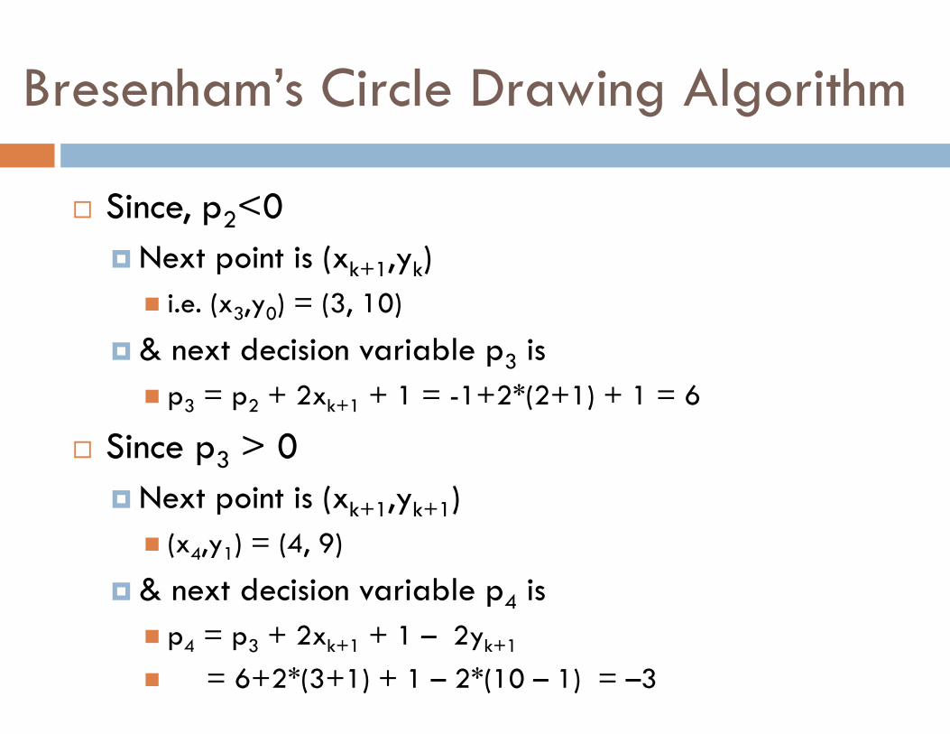
� Since, p2<0
� Next point is (xk+1,yk)
� i.e. (x3,y0) = (3, 10)
� & next decision variable p3 is
� p3 = p2 + 2xk+1 + 1 = -1+2*(2+1) + 1 = 6
� Since p3 > 0
� Next point is (xk+1,yk+1)
� (x4,y1) = (4, 9)
� & next decision variable p4 is
� p4 = p3 + 2xk+1 + 1 – 2yk+1
� = 6+2*(3+1) + 1 – 2*(10 – 1) = –3
Bresenham’s Circle Drawing Algorithm
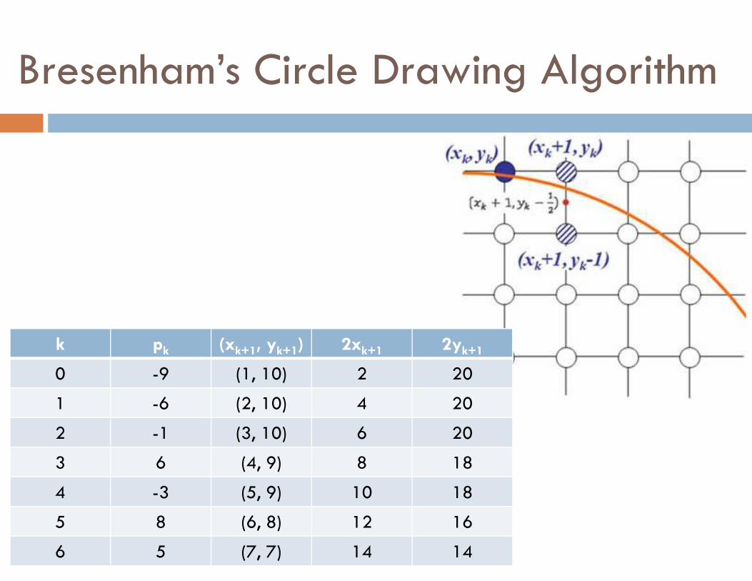
Bresenham’s Circle Drawing Algorithm
k pk (xk+1, yk+1) 2xk+1 2yk+1
0 -9 (1, 10) 2 20
1 -6 (2, 10) 4 20
2 -1 (3, 10) 6 20
3 6 (4, 9) 8 18
4 -3 (5, 9) 10 18
5 8 (6, 8) 12 16
6 5 (7, 7) 14 14
Bresenham’s Circle Drawing Algorithm
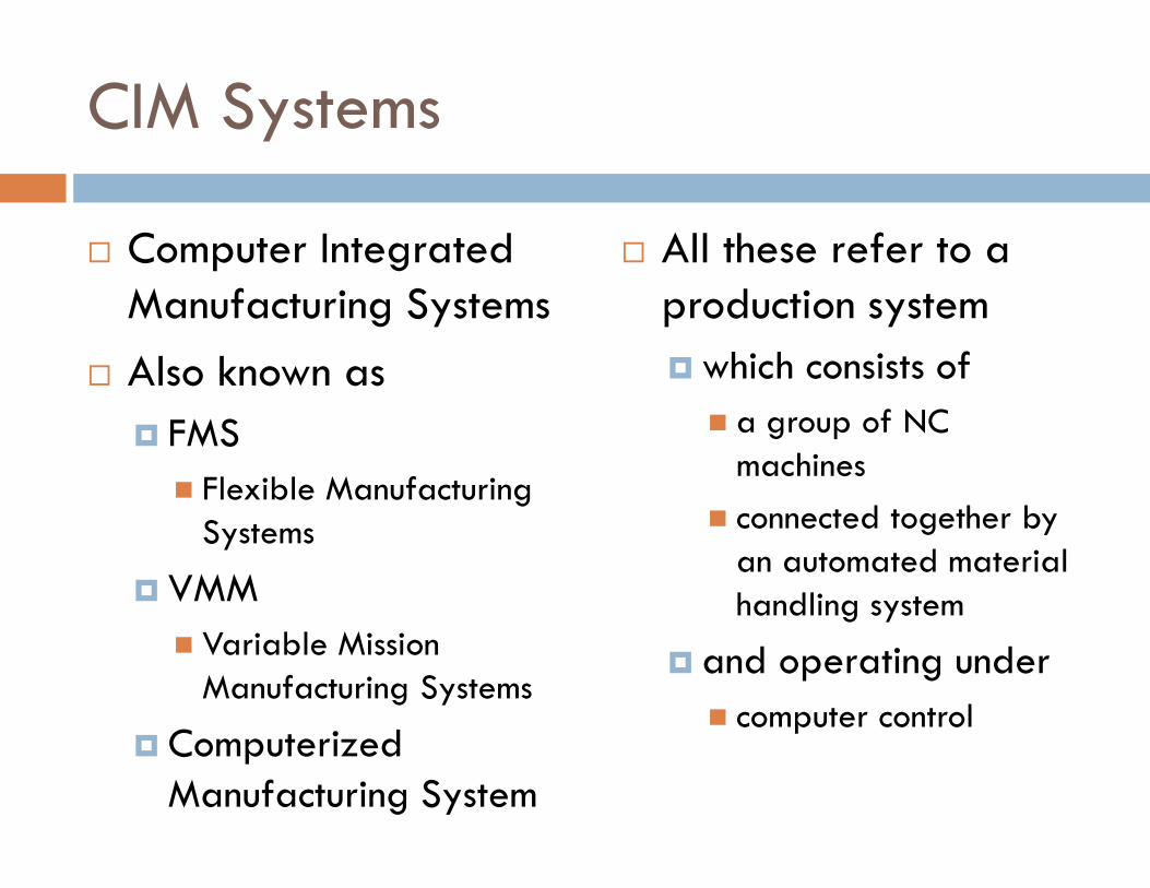
CIM Systems
� Computer Integrated Manufacturing Systems
� Also known as
� FMS
� Flexible Manufacturing Systems
� VMM
� Variable Mission Manufacturing Systems
� Computerized Manufacturing System
� All these refer to a production system
� which consists of
� a group of NC machines
� connected together by an automated material handling system
� and operating under
� computer control
CIMS
� Incorporates many individual CAD/CAM technologies & concepts
� CNC
� DNC
� Computer Process Control
� Computer Integrated Production Management
� Automated inspection methods
� Industrial Robotics
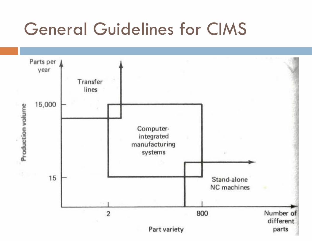
General Guidelines for CIMS
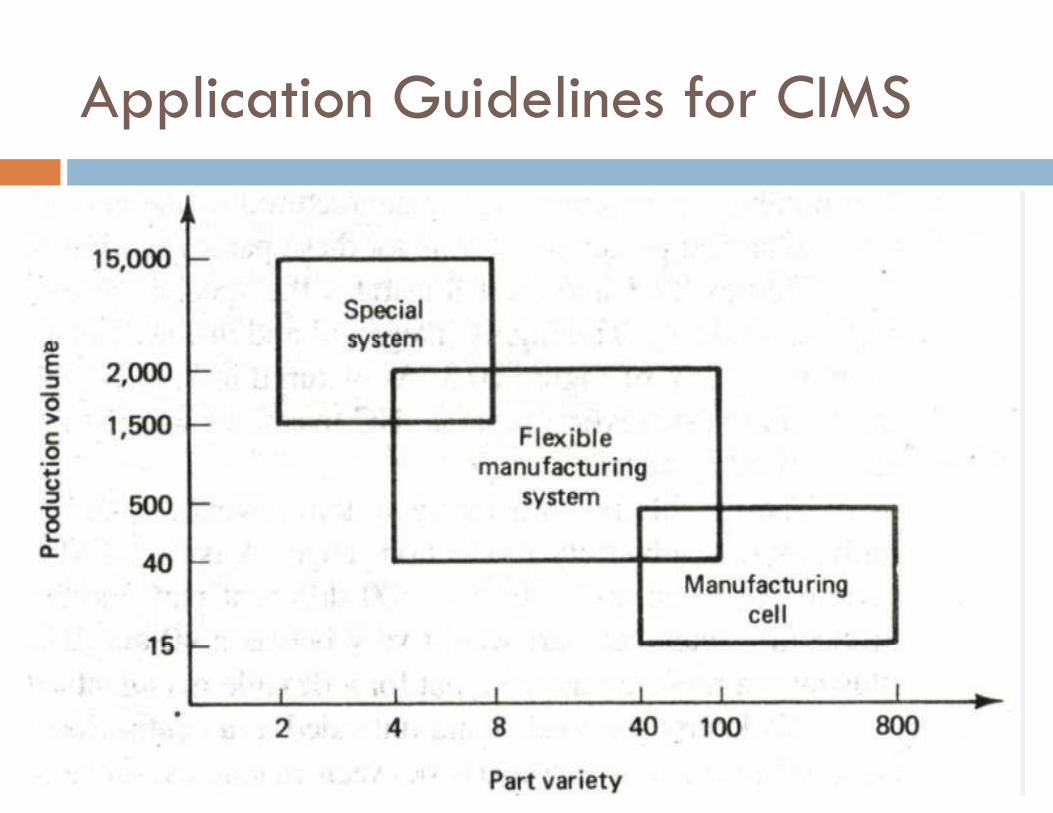
Application Guidelines for CIMS
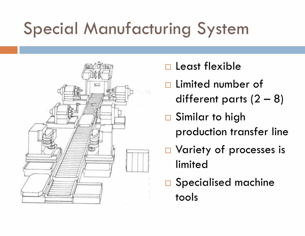
Special Manufacturing System
� Least flexible
� Limited number of different parts (2 – 8)
� Similar to high production transfer line
� Variety of processes is limited
� Specialised machine tools
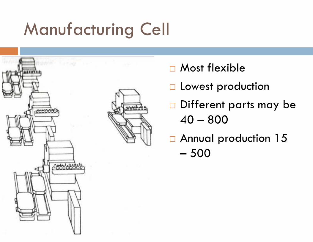
Manufacturing Cell
� Most flexible
� Lowest production
� Different parts may be 40 – 800
� Annual production 15 – 500
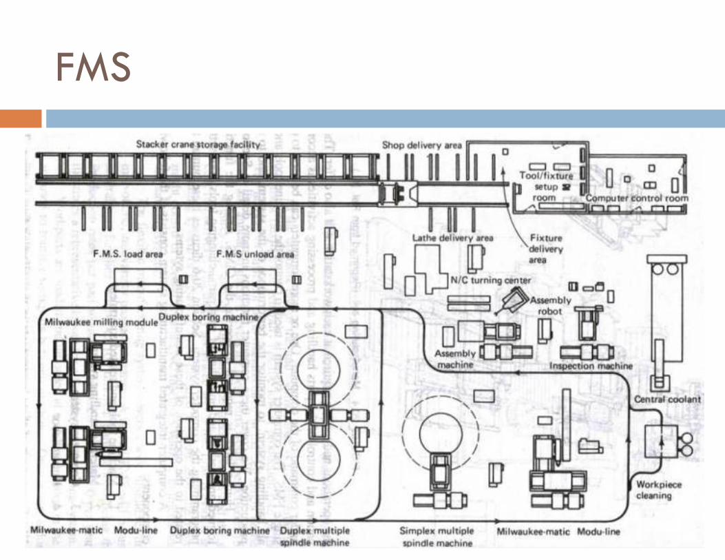
FMS
FMS
� 4 – 100 different parts
� 40 – 2000 parts per year
� Human labour required to operate

CIMS
� Machine tools & related equipment
� Materials handling systems
� Computer System
� Human Labor
1. Machine Tools & Related Equipment
� Standard CNC machine tools
� Special Purpose machine tools
� Tooling for these machines
� Inspection stations
� Inspection probes used with machine tools
Selection of machines for CIMS
� Part size
� Part shape
� Round - > Turning / Boring
� Cubical - > Milling / Drilling
� Flat - > Grinding
� Part Variety
� Product Life cycle
� Definition of future parts
� Operations other than machining
� Assembly
� Inspection
2. Material Handling System
� Functions
� Move workparts between machines
� Primary Work Handling systems
� Orient and locate workparts for processing at machines
� Secondary Work Handling systems
Primary Work Handling Systems
� Used to move parts between machine tools in CIMS
� Requirements
� Compatible with Computer Control
� Provide random, independent movement of palletized work parts
� Permit temporary storage or banking of workparts
� Allow access to machine tools for maintenance, tool changing, …..
� Interface with secondary work handling systems
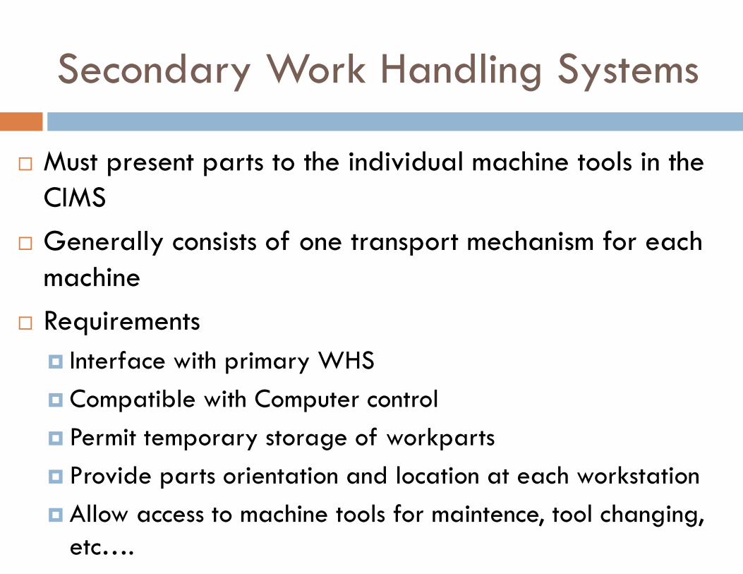
Secondary Work Handling Systems
� Must present parts to the individual machine tools in the CIMS
� Generally consists of one transport mechanism for each machine
� Requirements
� Interface with primary WHS
� Compatible with Computer control
� Permit temporary storage of workparts
� Provide parts orientation and location at each workstation
� Allow access to machine tools for maintence, tool changing, etc….
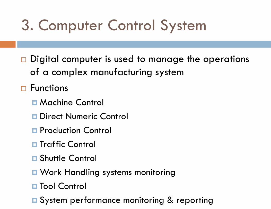
3. Computer Control System
� Digital computer is used to manage the operations of a complex manufacturing system
� Functions
� Machine Control
� Direct Numeric Control
� Production Control
� Traffic Control
� Shuttle Control
� Work Handling systems monitoring
� Tool Control
� System performance monitoring & reporting
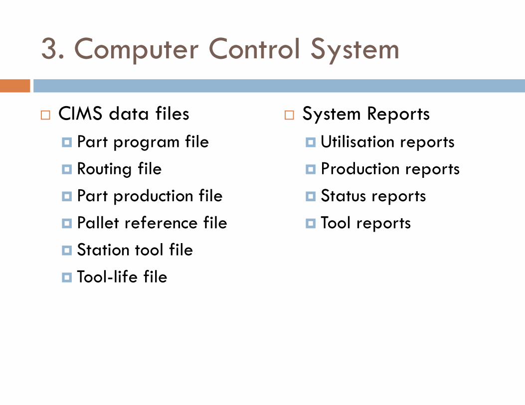
3. Computer Control System
� CIMS data files
� Part program file
� Routing file
� Part production file
� Pallet reference file
� Station tool file
� Tool-life file
� System Reports
� Utilisation reports
� Production reports
� Status reports
� Tool reports
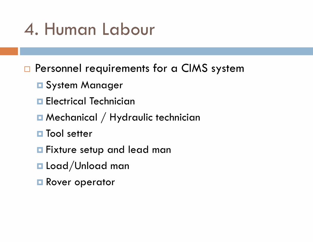
4. Human Labour
� Personnel requirements for a CIMS system
� System Manager
� Electrical Technician
� Mechanical / Hydraulic technician
� Tool setter
� Fixture setup and lead man
� Load/Unload man
� Rover operator
Benefits of CIM
� Increased machine utilisation
� Reduced direct and indirect labour
� Reduced manufacturing lead time
� Lower in-process inventory
� Scheduling flexibility