Slides for Chapter 3: Networking and Internetworking From Coulouris, Dollimore and Kindberg...
75
Slides for Chapter 3: Networking and Internetworking From Coulouris, Dollimore and Kindberg Distributed Systems: Concepts and Design Edition 4, © Pearson Education 2005
-
date post
20-Dec-2015 -
Category
Documents
-
view
230 -
download
6
Transcript of Slides for Chapter 3: Networking and Internetworking From Coulouris, Dollimore and Kindberg...

Slides for Chapter 3: Networking and Internetworking
From Coulouris, Dollimore and Kindberg
Distributed Systems: Concepts and Design
Edition 4, © Pearson Education 2005

Internet Architecture
The Design Philosophy of the DARPA Internet Protocols D. Clark, SIGCOMM
1998

Today’s Reading
Conceptual Lessons Design principles/priorities were designed for a
certain type of network. As the Internet evolves, we feel the sting of some of these choices.Examples: Commercialization
Engineering/Realization is key to testing an idea.
Technical Lessons Packet switching Fate Sharing/Soft state
Fundamental Goal
“technique for multiplexed utilization of existing interconnected networks”
Multiplexing (sharing) Shared use of a single communications channel
Existing networks (interconnection)

Fundamental Goal: Sharing
No connection setupForwarding based on destination address in packetEfficient sharing of resources
Tradeoff: Resource management potentially more difficult.
Packet Switching

Type of Packet Switching: Datagrams
Information for forwarding traffic is contained in destination address of packet
No state established ahead of time (helps fate sharing) Basic building block Minimal assumption about network service
AlternativesCircuit Switching: Signaling protocol sets up entire path out-of-band. (cf.
the phone network)Virtual Circuits: Hybrid approach. Packets carry “tags” to indicate path,
forwarding over IPSource routing: Complete route is contained in each data packet

An Age-Old Debate
Resource control, accounting, ability to “pin” paths, etc.
It is held that packet switching was one of the Internet’s greatest design choices.
Of course, there are constant attempts to shoehorn the best aspects of circuits into packet switching.
Examples: Capabilities, MPLS, ATM, IntServ QoS, etc.
Circuit Switching
Packet SwitchingSharing of resources, soft state (good resilience
properties), etc.

Stopping Unwanted Traffic is Hard
February 2000 March 2006
Research: Stopping Unwanted Traffic
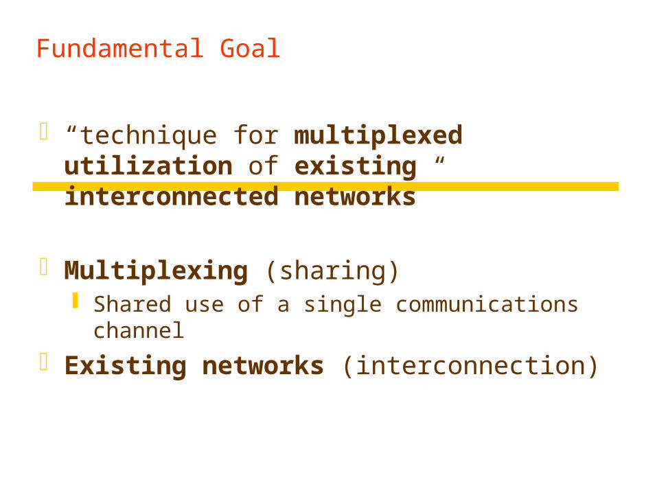
Datagram networks: easy for anyone to send traffic to anyone else…even if they don’t want it!
Possible DefensesMonitoring + Filtering: Detect DoS attack and install filters to drop
traffic.Capabilities: Only accept traffic that carries a “capability”
cnn.com

“This set of goals might seem to be nothing more than a checklist of all the desirable network features. It is important to understand that these goals are in order of importance, and an entirely different network architecture would result if the order were changed.”
The Design Goals of Internet, v1
Interconnection/Multiplexing (packet switching) Resilience/Survivability (fate sharing) Heterogeneity
Different types of services Different types of networks
Distributed management Cost effectiveness Ease of attachment Accountability
These goals were prioritized for a military network. Should priorities change as the network evolves?
DecreasingPriority

Fundamental Goal: Interconnection
Need to interconnect many existing networks Hide underlying technology from applications Decisions:
Network provides minimal functionality “Narrow waist”
Tradeoff: No assumptions, no guarantees.
Technology
Applications email WWW phone...
SMTP HTTP RTP...
TCP UDP…
IP
ethernet PPP…
CSMA async sonet...
copper fiber radio...

The “Curse of the Narrow Waist”
IP over anything, anything over IP Has allowed for much innovation both above and
below the IP layer of the stack An IP stack gets a device on the Internet
Drawback: very difficult to make changes to IP But…people are trying NSF GENI project: http://www.geni.net/
Interconnection: “Gateways”
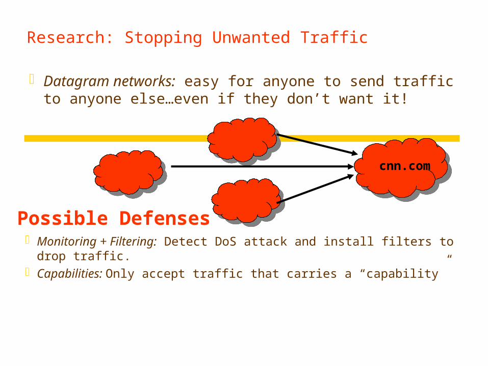
Interconnect heterogeneous networks No state about ongoing connections
Stateless packet switches
Generally, router == gateway But, we can think of your home router/NAT as also
performing the function of a gateway
Home Network Internet
192.168.1.51
192.168.1.52
68.211.6.120:50878
68.211.6.120:50879

Network Address Translation
For outbound traffic, the gateway: Creates a table entry for computer's local IP address
and port number Replaces the sending computer's non-routable IP
address with the gateway IP address. replaces the sending computer's source port
For inbound traffic, the gateway: checks the destination port on the packet rewrites the destination address and destination port
those in the table and forwards traffic to local machine

Goal #2: Survivability
Network should continue to work, even if some devices fail, are compromised, etc.
Failures on the Abilene (Internet 2) backbone network over the course of 6 months
How well does the current Internet support survivability?

Goal #2: Survivability
Replication Keep state at multiple places in the network, recover when nodes crash
Fate-sharing Acceptable to lose state information for some entity if the entity itself is lost
Two Options
Reasons for Fate Sharing Can support arbitrarily complex failure scenarios Engineering is easier
Some reversals of this trend: NAT, Routing Control Platform

Goal #3: Heterogeneous Services
TCP/IP designed as a monolithic transport TCP for flow control, reliable delivery IP for forwarding
Became clear that not every type of application would need reliable, in-order delivery Example: Voice and video over networks Example: DNS Why don’t these applications require reliable, in-order
delivery? Narrow waist: allowed proliferation of transport protocols

Goal #3b: Heterogeneous Networks
Build minimal functionality into the network No need to re-engineer for each type of network
“Best effort” service model. Lost packets Out-of-order packets No quality guarantees No information about failures, performance, etc.
Tradeoff: Network management more difficult

Goal #4: Distributed Management
Addressing (ARIN, RIPE, APNIC, etc.) Though this was recently threatened.
Naming (DNS)Routing (BGP)
Many examples:
No single entity in charge. Allows for organic growth, scalable management.
Tradeoff: No one party has visibility/control.

No Owner, No Responsible Party
Hard to figure out who/what’s causing a problemWorse yet, local actions have global effects…
“Some of the most significant problems with the Internet today relate to lack of sufficient tools for distributed
management, especially in the area of routing.”

Goal #5: Cost Effectiveness
Packet headers introduce high overheadEnd-to-end retransmission of lost packets
Potentially wasteful of bandwidth by placing burden on the edges of the network
Arguably a good tradeoff. Current trends are to exploit redundancy even more.

Goal #6: Ease of Attachment
IP is “plug and play” Anything with a working IP stack can connect to the Internet (hourglass model)
A huge success! Lesson: Lower the barrier to innovation/entry and people will
get creative (e.g., Cerf and Kahn probably did not think about IP stacks on phones, sensors, etc.)
But….
Tradeoff: Burden on end systems/programmers.

Goal #7: Accountability
Note: Accountability mentioned in early papers on TCP/IP, but not prioritized
Datagram networks make accounting tricky. The phone network has had an easier time figuring
out billing Payments/billing on the Internet is much less precise
Tradeoff: Broken payment models and incentives.

What’s Missing?
SecurityAvailabilityAccountability (the other kind)Support for disconnected/intermittent operationMobilityScaling…

Today’s Reading
Design Philosophy of the DARPA Internet Protocols. Dave Clark, 1988.
Conceptual Lessons Design principles/priorities were designed for a
certain type of network. As the Internet evolves, we feel the sting of some of these choices.Examples: Commercialization,
Engineering/Realization is key to testing an idea.Technical Lessons
Packet switching Fate Sharing/Soft state
Design Goal Shakeup
Cost of bandwidth is dropping. IP networks are becoming a commodity.
Management == Human intervention Costly!! Human error a leading cause of downtime
More bandwidth: are 40-byte headers still “big”?

Today’s Reading
Design Philosophy of the DARPA Internet Protocols. Dave Clark, 1988.
Conceptual Lessons Design principles/priorities were designed for a
certain type of network. As the Internet evolves, we feel the sting of some of these choices.Examples: Commercialization,
Engineering/Realization is key to testing an idea.Technical Lessons
Packet switching Fate Sharing/Soft state
Clark’s Paper and This Course
Flexible architectures (Good Thing) leave a lot of "wiggle room".
To determine whether something's going to work, it needs to be implemented/engineered.
Instructor’s Guide for Coulouris, Dollimore and Kindberg Distributed Systems: Concepts and Design Edn. 4 © Pearson Education 2005
Networking Issues (1)
Performance: Latency (time between send and start to receive) Data transfer rate (bits per second) Transmission time = latency + length / transfer rate System bandwidth, throughput: total volume of traffic
in a given amount of time Using different channels concurrently can make
bandwidth > data transfer rate traffic load can make bandwidth < data transfer rate network speed < memory speed (about 1000 times) network speed > disk speed (high-speed network file
servers can beat local disks)
Instructor’s Guide for Coulouris, Dollimore and Kindberg Distributed Systems: Concepts and Design Edn. 4 © Pearson Education 2005
Networking Issues (2)
scalability reliability
corruption is rare mechanisms in higher-layers to recover errors errors are usually timing failures, the receiver doesn't have
resources to handle the messages security
firewall on gateways (entry point to org's intranet) encryption is usually in higher-layers
mobility--communication is more challenging: locating, routing,...
quality of service--real-time services multicasting--one-to-many communication

Instructor’s Guide for Coulouris, Dollimore and Kindberg Distributed Systems: Concepts and Design Edn. 4 © Pearson Education 2005
Types of Networks (1)
Local Area Networks (LAN) floor/building-wide single communication medium no routing, broadcast segments connected by switches or hubs high bandwidth, low latency Ethernet - 10Mbps, 100Mbps, 1Gbps no latency guarantees (what could be the
consequences?) Personal area networks (PAN) [ad-hoc networks]:
blue tooth, infra-red for PDAs, cell phones, …
Instructor’s Guide for Coulouris, Dollimore and Kindberg Distributed Systems: Concepts and Design Edn. 4 © Pearson Education 2005
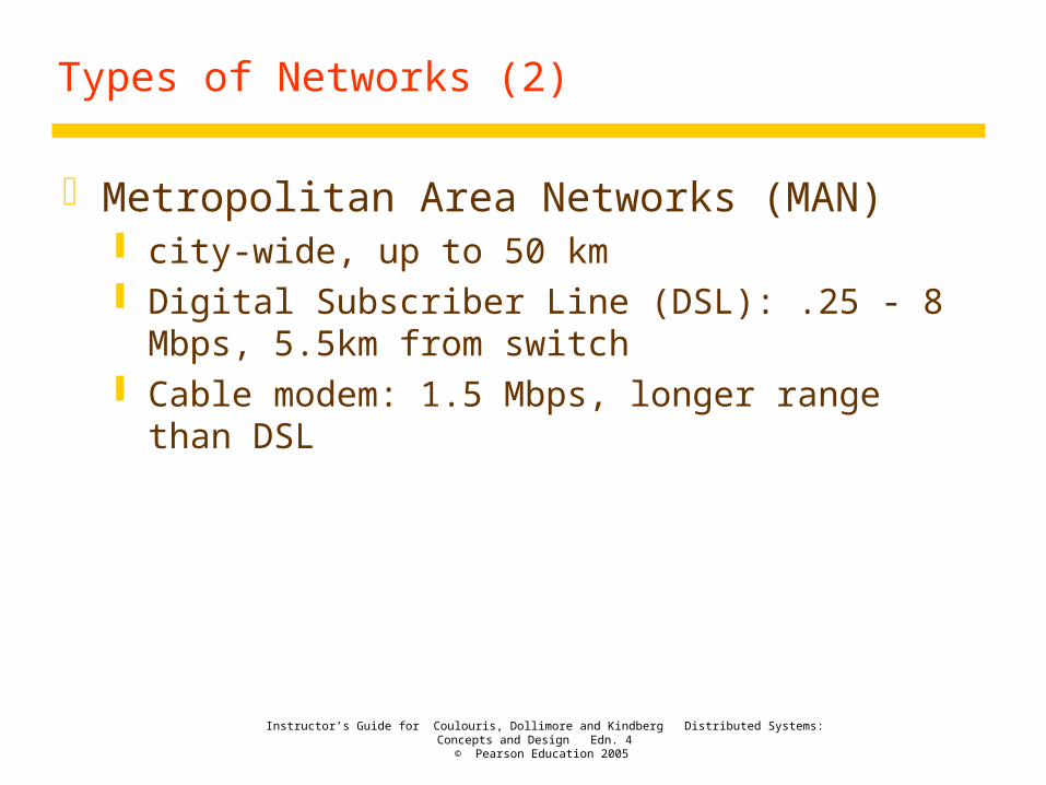
Types of Networks (2)
Metropolitan Area Networks (MAN) city-wide, up to 50 km Digital Subscriber Line (DSL): .25 - 8 Mbps, 5.5km
from switch Cable modem: 1.5 Mbps, longer range than DSL

Instructor’s Guide for Coulouris, Dollimore and Kindberg Distributed Systems: Concepts and Design Edn. 4 © Pearson Education 2005
Types of Networks (3)
Wide Area Networks (WAN) world-wide Different organizations Large distances routed, latency .1 - .5 seconds 1-10 Mbps (upto 600 Mbps)

Instructor’s Guide for Coulouris, Dollimore and Kindberg Distributed Systems: Concepts and Design Edn. 4 © Pearson Education 2005
Types of Networks (4)
Wireless local area networks (WLAN) IEEE 802.11 (WiFi) 10-100 Mbps, 1.5km
802.11 (1997): upto 2 Mbps, 2.4 GHz 802.11a (1999): upto 54 Mbps, 5 GHz, 60 feet 802.11b (1999): upto 11 Mbps, 2.4 GHz, 300 feet [most popular] 802.11g (2003): upto 54 Mbps, 2.4 GHz [backward compatible with
802.11b, becoming more popular]
Wireless metropolitan area networks (WMAN) IEEE 802.16 (WiMax) 1.5-20 Mbps, 5-50km
Instructor’s Guide for Coulouris, Dollimore and Kindberg Distributed Systems: Concepts and Design Edn. 4 © Pearson Education 2005
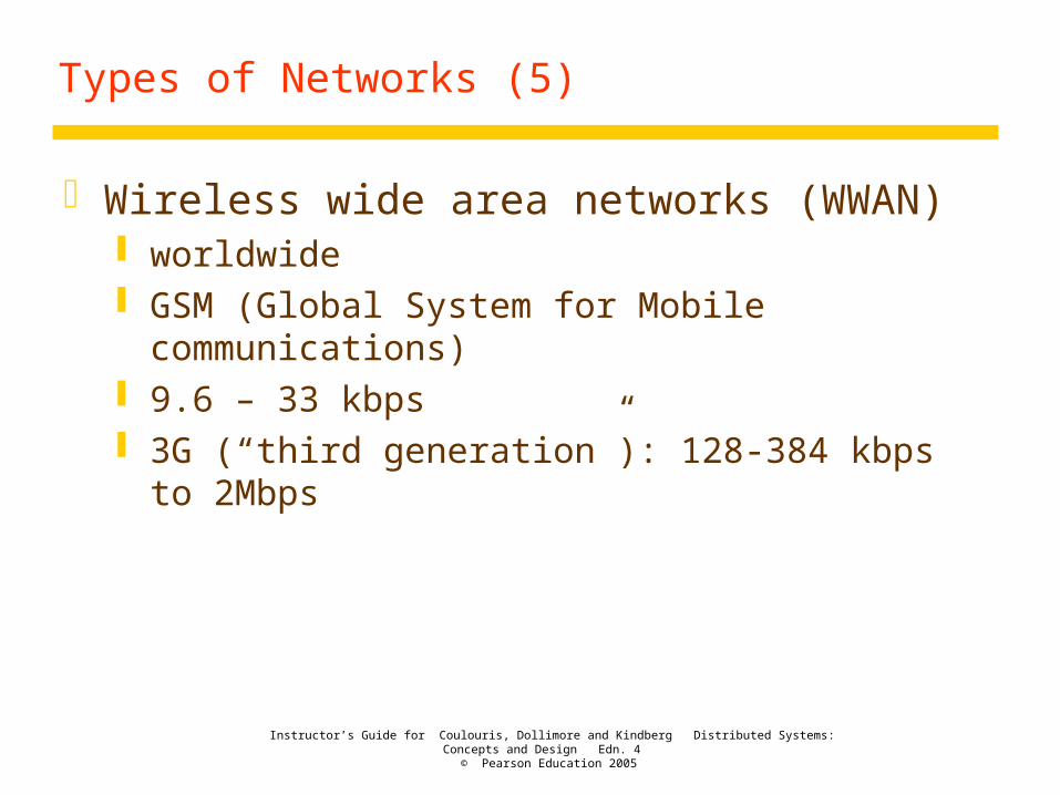
Types of Networks (5)
Wireless wide area networks (WWAN) worldwide GSM (Global System for Mobile communications) 9.6 – 33 kbps 3G (“third generation”): 128-384 kbps to 2Mbps

Instructor’s Guide for Coulouris, Dollimore and Kindberg Distributed Systems: Concepts and Design Edn. 4 © Pearson Education 2005
Types of Networks (6)
Internetworks connecting different kinds of networks routers, gateways

Instructor’s Guide for Coulouris, Dollimore and Kindberg Distributed Systems: Concepts and Design Edn. 4 © Pearson Education 2005
Network performance
Example Range Bandwidth(Mbps)
Latency(ms)
Wired:
LAN Ethernet 1-2 km 10-1000 1-10
MAN ATM 250 km 1-150 10
WAN IP routing worldwide .01-600 100-500
Internetwork Internet worldwide 0.5-600 100-500
Wireless:
WPAN Bluetooth (802.15.1) 10 - 30m 0.5-2 5-20
WLAN WiFi (IEEE 802.11) 0.15-1.5 km 2-54 5-20
WMAN WiMAX (802.16) 550 km 1.5-20 5-20
WWAN GSM, 3G phone nets worldwide 0.01-2 100-500

Instructor’s Guide for Coulouris, Dollimore and Kindberg Distributed Systems: Concepts and Design Edn. 4 © Pearson Education 2005
Network principles (1)
Packet transmission message: logical unit of informatio packet: transmission unit restricted length: sufficient buffer storage, reduce
hogging

Instructor’s Guide for Coulouris, Dollimore and Kindberg Distributed Systems: Concepts and Design Edn. 4 © Pearson Education 2005
Network principles (2)
Data Streaming audio/video Need 120 Mbps (1.5 Mbps compressed) play time: the time when a frame need to be
displayed for example, 24 frames per second, frame 48 must
be display after two seconds IP protocol provides no guaranteesIPv6 (new)
includes features for real-time streams, stream data are treated separately
Resource Reservation Protocol (RSVP), Real-time Transport Protocol (RTP)

Instructor’s Guide for Coulouris, Dollimore and Kindberg Distributed Systems: Concepts and Design Edn. 4 © Pearson Education 2005
Network principles (3)
Switching schemes (transmission between aribitrary nodes) Broadcast: ethernet, token ring, wireless Circuit switching: wires are connected Packet switching:
store-and-forward different routes “store-and-forward” needs to buffer the entire packet before
forwarding
Frame relay Small packets Looks only at the first few bits Don’t buffer/store the entire frame

Instructor’s Guide for Coulouris, Dollimore and Kindberg Distributed Systems: Concepts and Design Edn. 4 © Pearson Education 2005
Network principles (4)
Protocols Key components
Sequence of messages Format of messages
Instructor’s Guide for Coulouris, Dollimore and Kindberg Distributed Systems: Concepts and Design Edn. 4 © Pearson Education 2005
Network principles (5)
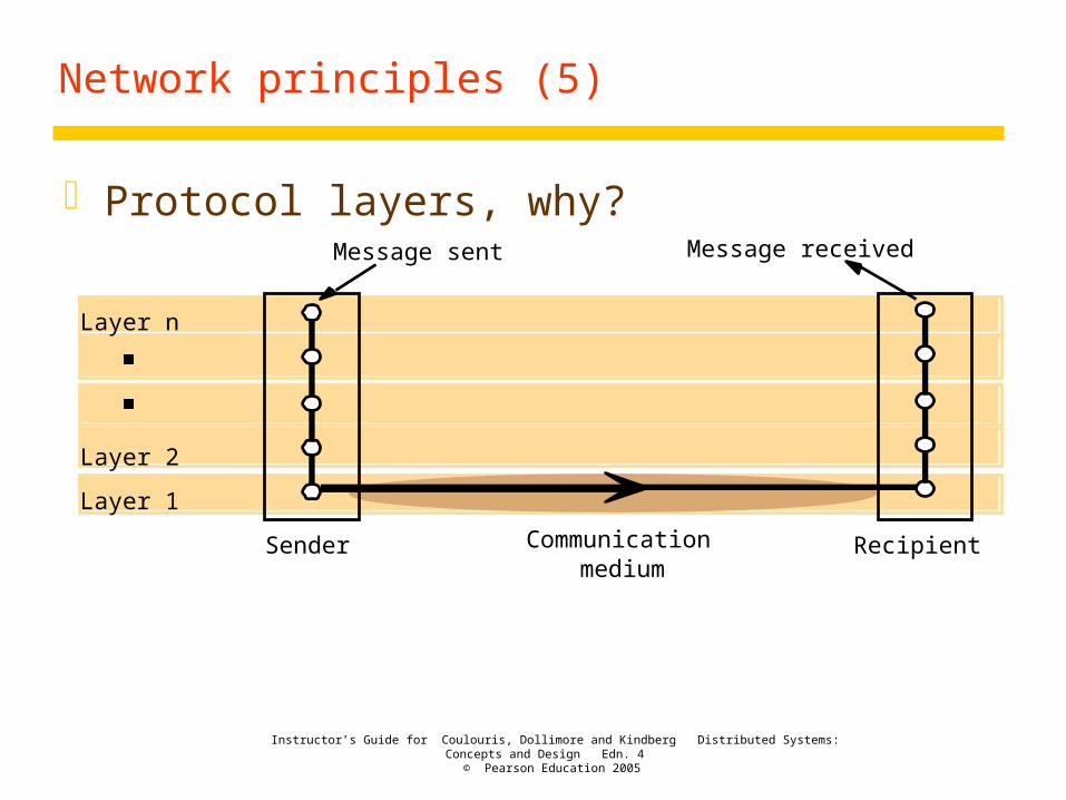
Protocol layers, why?
Layer n
Layer 2
Layer 1
Message sent Message received
Communicationmedium
Sender Recipient

Instructor’s Guide for Coulouris, Dollimore and Kindberg Distributed Systems: Concepts and Design Edn. 4 © Pearson Education 2005
Network principles (6)
Encapsulation in layered protocols
Presentation header
Application-layer message
Session header
Transport header
Network header

Instructor’s Guide for Coulouris, Dollimore and Kindberg Distributed Systems: Concepts and Design Edn. 4 © Pearson Education 2005
Network principles (7)
ISO Open Systems Interconnection (OSI) model
Application
Presentation
Session
Transport
Network
Data link
Physical
Message sent Message received
Sender Recipient
Layers
Communicationmedium
OSI Model
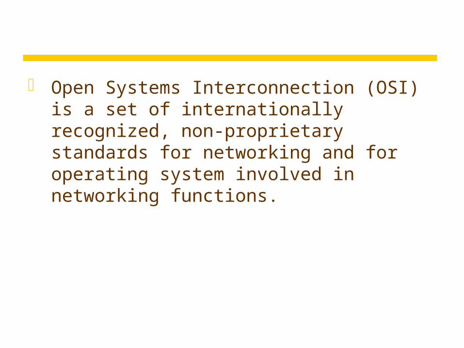
Open Systems Interconnection (OSI) is a set of internationally recognized, non-proprietary standards for networking and for operating system involved in networking functions.
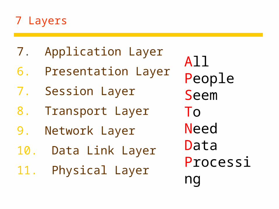
7 Layers
7. Application Layer
6. Presentation Layer
7. Session Layer
8. Transport Layer
9. Network Layer
10. Data Link Layer
11. Physical Layer
All People Seem To Need Data Processing

Tasks involved in sending letter

LAYER 7 – The APPLICATION Layer
The top layer of the OSI model
Provides a set of interfaces for sending and receiving applications to gain access to and use network services, such as: networked file transfer, message handling and database query processing

The application layer is responsible for providing services to the user.

LAYER 6 – The PRESENTATION Layer
Manages data-format information for networked communications (the network’s translator)
For outgoing messages, it converts data into a generic format for network transmission; for incoming messages, it converts data from the generic network format to a format that the receiving application can understand
This layer is also responsible for certain protocol conversions, data encryption/decryption, or data compression/decompression
A special software facility called a “redirector” operates at this layer to determine if a request is network related on not and forward network-related requests to an appropriate network resource

The presentation layer is responsible for translation, compression, and encryption.

LAYER 5 – The SESSION Layer
Enables two networked resources to hold ongoing communications (called a session) across a network
Applications on either end of the session are able to ex hange data for the duration of the session
This layer is:
Responsible for initiating, maintaining and terminating sessions
Responsible for security and access control to session information (via session participant identification)
Responsible for synchronization services, and for checkpoint services

The session layer is responsible for dialog control and synchronization.

LAYER 4 – The TRANSPORT Layer
Manages the transmission of data across a network
Manages the flow of data between parties by segmenting long data streams into smaller data chunks (based on allowed “packet” size for a given transmission medium)
Reassembles chunks into their original sequence at the receiving end
Provides acknowledgements of successful transmissions and requests resends for packets which arrive with errors

The transport layer is responsible for the delivery of a message from one process to another.

LAYER 3 – The NETWORK Layer
Handles addressing messages for delivery, as well as translating logical network addresses and names into their physical counterparts
Responsible for deciding how to route transmissions between computers
This layer also handles the decisions needed to get data from one point to the next point along a network path
This layer also handles packet switching and network congestion control

The network layer is responsible for the delivery of individual packets from
the source host to the destination host.

LAYER 2 – The DATA LINK Layer
Handles special data frames (packets) between the Network layer and the Physical layer
At the receiving end, this layer packages raw data from the physical layer into data frames for delivery to the Network layer
At the sending end this layer handles conversion of data into raw formats that can be handled by the Physical Layer

The data link layer is responsible for moving frames from one hop (node) to the next.

LAYER 1 – The PHYSICAL Layer
Converts bits into electronic signals for outgoing messages
Converts electronic signals into bits for incoming messages
This layer manages the interface between the the computer and the network medium (coax, twisted pair, etc.)
This layer tells the driver software for the MAU (media attachment unit, ex. network interface cards (NICs, modems, etc.)) what needs to be sent across the medium
The bottom layer of the OSI model

The physical layer is responsible for movements of individual bits from one hop (node) to the next.
Remember
A convenient aid for remembering the OSI layer names is to use the first letter of each word in the phrase:
All People Seem To Need Data Processing


Instructor’s Guide for Coulouris, Dollimore and Kindberg Distributed Systems: Concepts and Design Edn. 4 © Pearson Education 2005
Network principles (8)
Internet layers Application = application + presentation Transport = transport + session
Underlying network
Application
Network interface
Transport
Internetwork
Internetwork packets
Network-specific packets
MessageLayers
Internetworkprotocols
Underlyingnetworkprotocols

Instructor’s Guide for Coulouris, Dollimore and Kindberg Distributed Systems: Concepts and Design Edn. 4 © Pearson Education 2005
Network principles (9)
Packet assembly header and data maximum transfer unit (MTU): 1500 for Ethernet 64K for IP (8K is common because of node storage)
ports: destination abstraction (application/service protocol)
addressing: transport address = network address + port Well-known ports (below 1023) Registered ports (1024 - 49151) Private (up to 65535)

Instructor’s Guide for Coulouris, Dollimore and Kindberg Distributed Systems: Concepts and Design Edn. 4 © Pearson Education 2005
Network principles (10)
Packet delivery (at the network layer) Datagram packet
one-shot, no initial set up different routes, out of order Ethernet, IP
Virtual circuit packet initial set up for resources virtual circuit # for addressing ATM
Similar but different pairs of protocols at the transport layer (connection-oriented and connectionless)
Instructor’s Guide for Coulouris, Dollimore and Kindberg Distributed Systems: Concepts and Design Edn. 4 © Pearson Education 2005
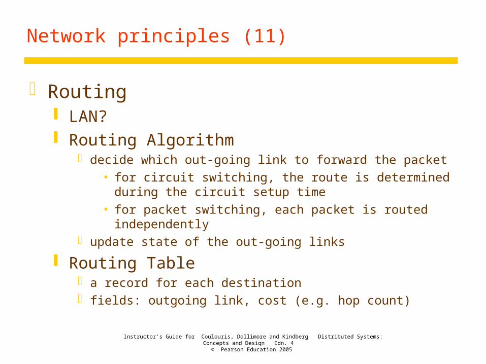
Network principles (11)
Routing LAN? Routing Algorithm
decide which out-going link to forward the packet
• for circuit switching, the route is determined during the circuit setup time
• for packet switching, each packet is routed independently update state of the out-going links
Routing Table a record for each destination fields: outgoing link, cost (e.g. hop count)

Instructor’s Guide for Coulouris, Dollimore and Kindberg Distributed Systems: Concepts and Design Edn. 4 © Pearson Education 2005
Network principles (12)
Router example
Hosts Linksor local networks
A
D E
B
C
12
5
43
6
Routers
Instructor’s Guide for Coulouris, Dollimore and Kindberg Distributed Systems: Concepts and Design Edn. 4 © Pearson Education 2005
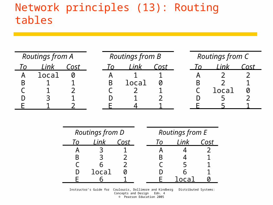
Network principles (13): Routing tables
Routings from D Routings from E
To Link Cost To Link CostABCDE
336
local6
12201
ABCDE
4456
local
21110
Routings from A Routings from B Routings from C
To Link Cost To Link Cost To Link CostABCDE
local1131
01212
ABCDE
1local
214
10121
ABCDE
22
local55
21021
Instructor’s Guide for Coulouris, Dollimore and Kindberg Distributed Systems: Concepts and Design Edn. 4 © Pearson Education 2005
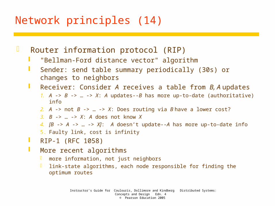
Network principles (14)
Router information protocol (RIP) "Bellman-Ford distance vector" algorithm Sender: send table summary periodically (30s) or changes to
neighbors Receiver: Consider A receives a table from B, A updates
1. A -> B -> … -> X: A updates--B has more up-to-date (authoritative) info
2. A -> not B -> … -> X: Does routing via B have a lower cost?
3. B -> … -> X: A does not know X
4. [B -> A -> … -> X]: A doesn’t update--A has more up-to-date info
5. Faulty link, cost is infinity
RIP-1 (RFC 1058) More recent algorithms
more information, not just neighbors link-state algorithms, each node responsible for finding the optimum routes

Instructor’s Guide for Coulouris, Dollimore and Kindberg Distributed Systems: Concepts and Design Edn. 4 © Pearson Education 2005
Network principles (15): Pseudocode for RIP routing algorithm
Tl is the table local table; Tr is the received remote table
Send: Each t seconds or when Tl changes, send Tl on each non-faulty outgoing link.Receive: Whenever a routing table Tr is received on link n:
for all rows Rr in Tr {if (Rr.link != n) { // destination not routed via the receiver
Rr.cost = Rr.cost + 1;Rr.link = n;if (Rr.destination is not in Tl) add Rr to Tl; // add new destination to Tlelse for all rows Rl in Tl {
if (Rr.destination = Rl.destination and (Rr.cost < Rl.cost or Rl.link = n)) Rl
= Rr;// Rr.cost < Rl.cost : remote node has better route// Rl.link = n : remote node is more authoritative
}}
}

Instructor’s Guide for Coulouris, Dollimore and Kindberg Distributed Systems: Concepts and Design Edn. 4 © Pearson Education 2005
Network principles (16)
Congestion control high traffic load, packets dropped due to limited
resources reducing transmission rate: "choke packets" from
sender to receiver
Instructor’s Guide for Coulouris, Dollimore and Kindberg Distributed Systems: Concepts and Design Edn. 4 © Pearson Education 2005
Networking principles (17)
Network connecting devices Hubs: extending a segment of LAN (broadcast) Switches: switching traffic at data-link level (different
segments of a LAN), making temporary hardware connections between two ports (or store and forward) [switches do not exchange info with each other]
Routers: routing traffic at IP level Bridges: linking networks of different types, could be
routers as well
Instructor’s Guide for Coulouris, Dollimore and Kindberg Distributed Systems: Concepts and Design Edn. 4 © Pearson Education 2005
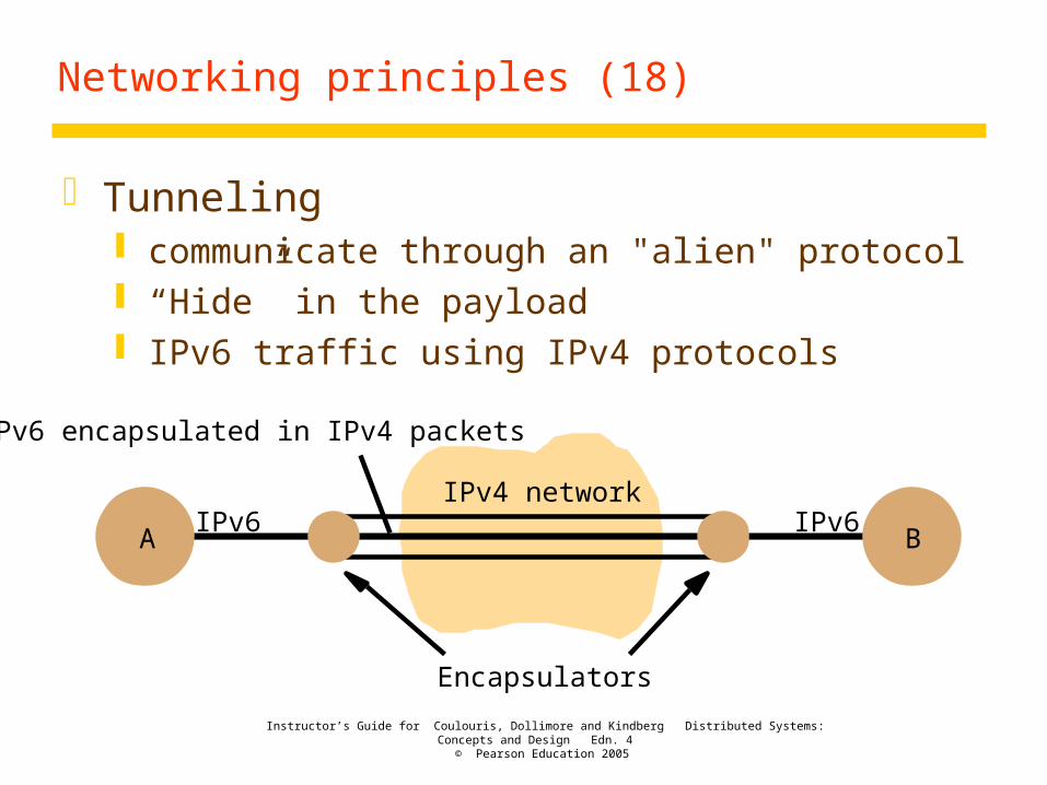
Networking principles (18)
Tunneling communicate through an "alien" protocol “Hide” in the payload IPv6 traffic using IPv4 protocols
A BIPv6 IPv6
IPv6 encapsulated in IPv4 packets
Encapsulators
IPv4 network