SLIDE WRITER ™ Film Recorder - MOPS Computer
49
AGFA MATRIX DIVISION SLIDEWRITER ™ Film Recorder
Transcript of SLIDE WRITER ™ Film Recorder - MOPS Computer

AGFA MATRIX DIVISION
SLIDE WRITER ™
Film Recorder

CHAPTER 1
CHAPTER 2
CHAPTER 3
CHAPTER 4
CHAPTER 5
TABLE OF CONTENTSSlideWriter OWNER'S GUIDE
UNPACKING AND PREPARATIONSlideWriter Accessory Kit ................................Power Requirements ....................................EMI/RFI ...............................................Space Requirements ...................................Environmental Requirements . . . . . . . . . . . . . . . . . . . . . . . . . . . . .Controls and Connectors ................................
Display Panel ..............................................Rear Panel .........................................
INSTALLATIONConnecting the Power Line ...... . . . . . . . . . . . . . . . . . . . . . . . .Connecting the SCSI Interface Cables .....................
Some Rules to Follow When You Connect the SlideWriter . .SlideWriter Installation Configurations . . . . . . . . . . . . . . . . . . .
OPERATOR INSTRUCTIONSPower-Up Sequence . . . . . . . . . . . . . . . . . . . . . . . . . . . . . . . . . . .Loading Film . . . . . . . . . . . . . . . . . . . . . . . . . . . . . . . . . . . . . . . . . .Taking an Exposure . . . . . . . . . . . . . . . . . . . . . . . . . . . . . . . . . . . .Unloading Film .. . . . . . . . . . . . . . . . . . . . . . . . . . . . . . . . . . . . . . . .
SlideWriter MAINTENANCEGeneral Maintenance ...................................SlideWriter Test Operations ..............................
Running a Test Pattern Without Film .. . . . . . . . . . . . . . . . . . .Running a Test Pattern With Film ... . . . . . . . . . . . . . . . . . . . .
REFERENCESystem Description . . . . . . . . . . . . . . . . . . . . . . . . . . . . . . . . . . . . .
Components of SlideWriter . . . . . . . . . . . . . . . . . . . . . . . . . . . .SlideWriter System Overview . . . . . . . . . . . . . . . . . . . . . . . . . .
Power-Up and System Reset . . . . . . . . . . . . . . . . . . . . . . . . . . . .Function Numbers . . . . . . . . . . . . . . . . . . . . . . . . . . . . . . . . . . . . . .The SlideWriter Beeper . . . . . . . . . . . . . . . . . . . . . . . . . . . . . . . . .Programming SCSI Device Address . . . . . . . . . . . . . . . . . . . . . .SlideWriter Error Codes . . . . . . . . . . . . . . . . . . . . . . . . . . . . . . . . .Setting SlideWriter as an Unterminated SCSI Device . . . . . . . . .
Side Cover Removal . . . . . . . . . . . . . . . . . . . . . . . . . . . . . . . . .Low Voltage Power Supply Removal . . . . . . . . . . . . . . . . . . . .
Glossary of Terms .....................................Index ......................................................
12222446
781011
13151819
20202122
23232425273132343940414245
LIST OF ILLUSTRATIONS
Figure 1-1.Figure 1-2.Figure 1-3.Figure 1-4.
Figure 2-1.Figure 2-2.Figure 2-3.Figure 2-4.Figure 2-5.
Figure 2-6.
Figure 3-1.Figure 3-2.Figure 3-3.Figure 3-4.
Figure 5-1.Figure 5-2.Figure 5-3.Figure 5-4.Figure 5-5.
Table 5-1.Table 5-2.Table 5-3.
SlideWriter Accessory Kit ...........................................SlideWriter Dimensions and External Features ........................Switch and Light Identification .....................................Switch and Connector Identification ................................
Power Switch and Connector Location ..............................SCSI Connectors and Cables .....................................Single Device-Setup, Both Host and SlideWriter Terminated Internally ....Single Device Setup, Macintosh Pius with Cable Extender ..............Recommended Multiple Device Setup,
Both Host and SlideWriter Terminated Internally ...................Alternate Multiple Setup with SlideWriter Unterminated
and in the Middle of the Device Chain ..........................
Power Switch Location ...........................................Major Components of the Pentax A3000 35mm Camera . . . . . . . . . . . . . . .Loading the Pentax A3000 35mm Camera . . . . . . . . . . . . . . . . . . . . . . . . . . .Unloading the Pentax A3000 35mm Camera . . . . . . . . . . . . . . . . . . . . . . . . .
SlideWriter Major Components . . . . . . . . . . . . . . . . . . . . . . . . . . . . . . . . . . . .SlideWriter Imaging Process .......................................Location of the SCSI DIP Switch ...................................Side Cover Removal .............................................Low Voltage Power Supply Removal ................................
Numbered SlideWriter Functions ...................................Device Address Settings . . . . . . . . . . . . . . . . . . . . . . . . . . . . . . . . . . . . . . . . .Primary Error and Fault Code Interpretations . . . . . . . . . . . . . . . . . . . . . . . .
1346
781111
12
12
13151719
2324323940
283334
//

PREFACE
About This Manual This manual provides the steps needed to install, operate, andmaintain optimum performance of the SlideWriter. The first fourchapters provide the information needed to produce slides. The fifthchapter will provide the basics of how the SlideWriter works. Thefollowing is an overview of each chapter in this manual:
Chapter 1: Unpacking and Preparation - introduces themachine, its controls, and connectors. This chapteralso contains information on choosing a place to putyour SlideWriter.
Chapter 2: Installation - Connecting your SlideWriter to aMacintoshTM computer.
Chapter 3: Operator Instructions - includes procedures onloading and unloading film and taking an exposure onthe SlideWriter.
Chapter 4: SlideWriter Maintenance - Contains informationon keeping your film recorder in proper working orderand procedures for testing SlideWriter.
Chapter 5: Reference - Contains a system overview, aglossary, and a description of function numbers anderror codes.
Additional information regarding the software is contained in a separatebooklet, SlideWriter Utility Software User's Guide.
As with any standard office equipment, a service contract is recommendedfor the Matrix SlideWriter. Contact your authorized Matrix representative fordetails.
KODAK and Ektachrome are trademarks of Eastman KODAK Company.MacintoshTM is a trademark of Apple Computer.Pentax is a registered trademark of Pentax Corporation.Polacolor Is a trademark of Polaroid Corporation.SlideWriter is a trademark of Matrix Instruments, Inc.

Introduction
The Matrix SlideWriter produces full color 35mm slides of outstandingquality with both 2048 x 1366 (2k) and 4096 x 2732 (4k) resolutions(software selectable).
The SlideWriter is designed to be used with any computer that uses aSCSI (Small Computer System Interface) interface. The SlideWriter'sfunctions may be controlled from the host computer.
IV


PowerRequirements
EMI/RFI
SpaceRequirements
CAUTION
EnvironmentalRequirements
Film Types
The SlideWriter requires either 110 VAC, 60 Hz or 220 VAC, 50 Hzdepending on individual power specifications. The SlideWriter'spower requirements are on the serial number identification labellocated on the rear of the unit.
The SlideWriter draws approximately 1.5 Amps. Before installing it,ensure that adequate power is available. Because the SlideWriter isa precision electro-optical device, it is important that the voltagespecifications and power requirements are specifically adhered to.
If the power system has other large electrical machinery connectedto it, or it is subject to variations such as transients, voltage sagsand surges, or brownouts, use a use a power line conditioner suchas the Elgar Power Line Conditioner (PLC) Model PLC 250.
This equipment has been tested and complies with the limits for acomputing device in accordance with the specifications in Subpart J,Part 15, Class A, of FCC rules.
The SlideWriter film recorder measures 17.7 (length) x 11.5 (width)x 35.8 (height with wheels) inches (450 x 292 x 910 mm). It weighs42 Ibs. (19 kg). Because the SlideWriter stands vertically, 17.7 x11.5 inches constitutes the required floor space. Keep the spaceabove the unit clear to facilitate film loading.
The internal CRT uses magnetic coils to position an electronicimaging beam. Although the SlideWriter contains shields from externalmagnetic fields, it should be located as far as possible fromcomputer tape drives, disk drives, fans, or any other device withmagnetic switching. This will minimize interference from these devicesduring imaging.
Storage Temperature: 32° to 158° F (0° to 70° C)Operating Temperature: 59° to 86° F (15° to 30° C)Relative Humidity: 35% to 65% non-condensing
The SlideWriter supports Kodak Ektachrome ASA 100 35mm film andPolacolor HC 35mm instant slide film.
2

Figure 1-2. SlideWriter Dimensions and External Features
3

Controls and Connectors
Display Panel
The following describes the functions of the SlideWriter's controls,display and connectors.
1. RESET SWITCH2. FUNCTION SWITCH3. SELECT SWITCH4. READY LIGHT5. REMOTE LIGHT
6. FAULT & ERROR LIGHTS7. RECORD LIGHT8. RED, GREEN, BLUE LIGHTS9. CURRENT EXPOSURE
DISPLAY
1. Reset
2. Function
Figure 1-3. Switch and Light Identification
This switch initiates a system reset and moves the filter wheel (threecolored glass lenses) to the neutral position.
This allows selection of an internal function when the SlideWriterready light (4) is on. Pressing this switch displays the number of thefunction on the Current Exposure Display. Press it repeatedly or holdit down to increase the displayed number to the function numberdesired. If the desired number is passed, the SlideWriter will repeatthe numbers 1 to 11. A complete description of these functions canbe found in section 5.
4

3. Select
4. Ready
5. Remote
6. Fault and Error
7. Record
8. Red, Green, and Blue
9. Current ExposureDisplay
NOTE
Press this switch to initiate the function displayed on the CurrentExposure Display.
This signal light announces that the SlideWriter is ready to acceptcommands.
This signal light indicates that the SlideWriter is processing acommand from the host computer.
These lights indicate either a fault or an error condition. TheSlideWriter will issue a two-second-long warning alarm every fifteensecond until a system reset occurs. When either light is on, theCurrent Exposure Display exhibits a primary hexadecimal error code.(See page 34 for an explanation of each error code.)
This signal light indicates that the SlideWriter is recording an image.
These lights indicate which color is being recorded when the Recordlight is on. When all three are off, the wheel is in the neutralposition. When all three are on, the wheel is changing from onecolor to another.
When the three signal lights flicker randomly, the SlideWriter isperforming an automatic intensity calibration.
This operates under three conditions:
• During normal operation, the displayed digits indicate the filmframe the SlideWriter is currently exposing. A double dash ( - - )means that the film has run out, that no film is present, or that the"film load" function has not been set.
• A numerical display concurrent with an illuminated Fault or Errorlight indicates the error code. (See page 34 for a detailedexplanation of error codes.)
• If the Function switch is pressed, the Current Exposure Displayshows the function number currently selected.
The display will flash continuously while in the function mode. This ispart of normal operation.
5

Rear Panel
1. SCSI CONNECTORS2. FUSE
3. SOCKET4. POWER SWITCH
1. SCSI Connectors
2. Fuse
3. Socket
4. Power Switch
Figure 1-4. Switch and Connector Identification
Connectors which accept the SCSI interface cable allowing thetransmission of data and commands to the SlideWriter. Twoconnectors are provided to permit looping through from theSlideWriter to another device on the SCSI bus. The SCSI interfacecable can be connected to either connector on the SlideWriter'sRear Panel.
Protects the electrical system of the unit. It breaks the circuit whenthe current exceeds the rated value. The fuse value is stamped inthe serial number tag.
Input connector for line power.
Pressing this switch to the right turns on the SlideWriter.
6

INSTALLATION
Connecting the Power Line
WARNING
NOTE
Figure 2-1. POWER Switch and Connector Location
Read all the installation instructions carefully before you plug in yourSlideWriter. Follow all the instructions and warnings dealing with yoursystem. Keep this manual handy for reference by you and others.
To connect the SlideWriter's power line:
• Ensure that the SlideWriter's POWER Switch is in the OFFposition.
• Connect the female end of the AC power cord supplied with theSlideWriter to the three-pronged socket on the rear panel.
» Ensure that the AC current provided matches the specificationgiven on the SlideWriter's serial number tag. Plug the three-prongedmale end into a standard AC power socket.
The SlideWriter is intended to be electrically grounded. TheSlideWriter's AC connector will fit only a grounding-type AC outlet.This is a safety feature.
If you are unable to insert the plug into the outlet, contact a licensedelectrician to replace the outlet with a properly grounded outlet.
Do not defeat the purpose of the grounding plug!
You should use a power line conditioner if your AC is subject tovariants such as voltage drops, surges or brownouts.
7

Connecting the SCSI Interface Cable
Figure 2-2. SCSI Interface Connectors and Cables
This section provides you with instructions for connecting theSlideWriter onto the SCSI computer bus. Two cables and an in-linecable terminator are included in the SlideWriter accessory kit.
8

SCSI System Cable
Cable Extender
Cable Terminator
The SCSI system cable (part number 01-06-054) is included forApple Macintosh users. This short cable connects between the SCSIport on the Macintosh and the first device in the chain.
The cable extender (part number 01-06-053) has a 50 pin plugconnector at on end and a 50 pin socket connector at the otherend. This cable will receive a cable terminator or peripheralinterface cable, and plug into the next device in the chain.
The cable terminator (part number 01-06-052) connects to the50 pin end of the SCSI system cable when you are using aMacintosh Plus. The external terminator is required for SlideWriterswhich do not have internal termination for the SCSI bus. Theterminator is not a SCSI device. Its purpose is simply to minimizesignal reflections and noise in the interconnecting cables.
9

Some Rules to FollowWhen You. Connectthe SlideWriter • Be certain the host computer and SlideWriter's AC power is off
before connecting or disconnecting the SCSI cables.
• Do not exceed a total of 6 meters (19.7 feet) in combined cablelength among all devices on the SCSI bus.
• A number of suggested device layouts are provided on thefollowing page. Ensure that you terminate both ends of the SCSI busfor whichever arrangement you decide upon.
• Check to see if the host computer has internal SCSI bustermination. Some systems such as the Macintosh Plus do not, andrequire an external terminator plug as described above. Neverdouble terminate either end of the SCSI bus.
• The SlideWriter has internal SCSI bus termination. If you decideto install the SlideWriter in the middle of the device chain, as inFigure 2-6, then its terminators must be removed. Refer to page 39of this manual for complete instructions.
» In order to guarantee secure cable connections between devicesyou should fasten the interlocking wire clips or screws on theconnector ends, and ensure that adequate strain relief is providedwherever cables connect into the devices.
10

SlideWriterInstallation Configurations
• Connect the SlideWriter on the SCSI Bus using one of theconfigurations shown in the following illustrations.
SingleDeviceSetups
Figure 2-4. Single Device Setup, Both Host and SlideWriter Terminated Internally
Figure 2-3. Single Device Setup, Unterminated Macintosh Plus with Cable Extender
11

MultipleDeviceSetups
Figure 2-5. Recommended Multiple Device Setup, Both Host andSlideWriter Terminated Internally
Figure 2-6. Alternate Multiple Device Setup with SlideWriter Unterminatedand in the Middle of the Device Chain
72
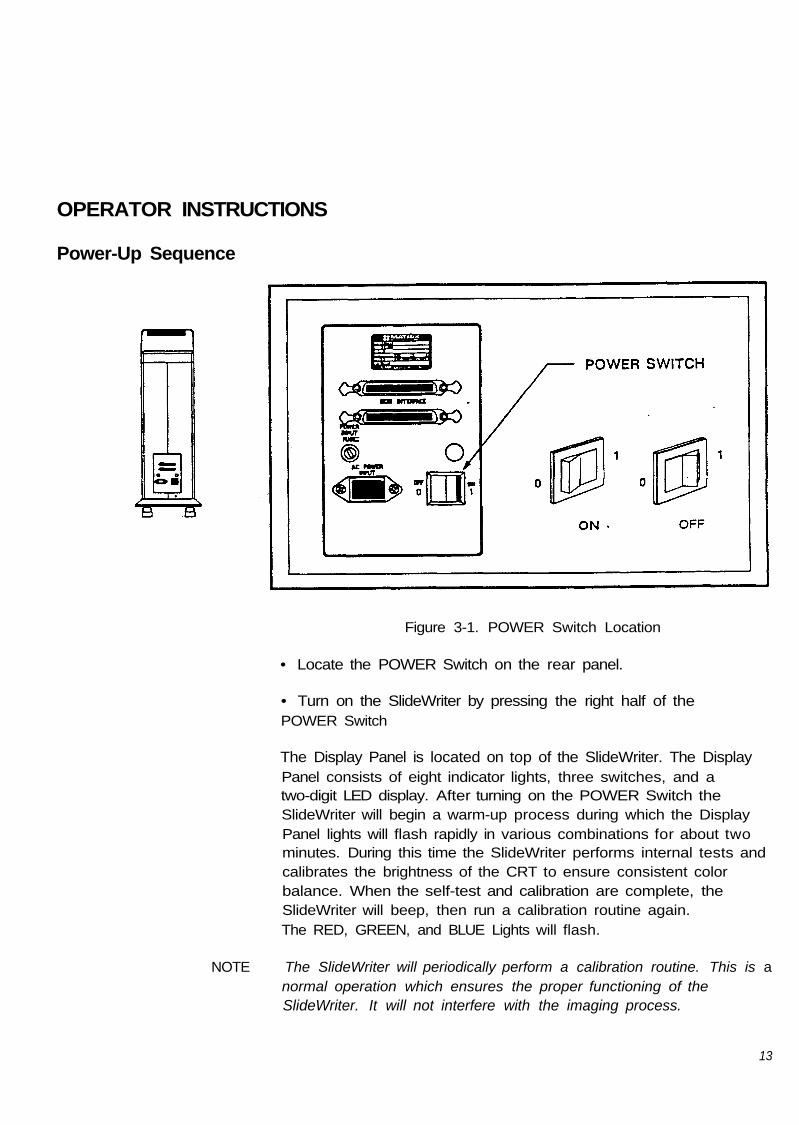
OPERATOR INSTRUCTIONS
Power-Up Sequence
Figure 3-1. POWER Switch Location
• Locate the POWER Switch on the rear panel.
• Turn on the SlideWriter by pressing the right half of thePOWER Switch
The Display Panel is located on top of the SlideWriter. The DisplayPanel consists of eight indicator lights, three switches, and atwo-digit LED display. After turning on the POWER Switch theSlideWriter will begin a warm-up process during which the DisplayPanel lights will flash rapidly in various combinations for about twominutes. During this time the SlideWriter performs internal tests andcalibrates the brightness of the CRT to ensure consistent colorbalance. When the self-test and calibration are complete, theSlideWriter will beep, then run a calibration routine again.The RED, GREEN, and BLUE Lights will flash.
NOTE The SlideWriter will periodically perform a calibration routine. This is anormal operation which ensures the proper functioning of theSlideWriter. It will not interfere with the imaging process.
13

When only the READY light is on, the self-test and calibrationroutine is complete. Two dashes will appear in the CURRENTEXPOSURE Display provided that no film was loaded or advancedsince power-up.
I f the ERROR or FAULT lights flash and the SlideWriter beeps,locate the error code displayed in the CURRENT EXPOSURE Displayand refer to page 30 for an error explanation. Although theSlideWriter is ready for use upon warm-up completion(approximately two to four minutes), an hour wait is recommendedbefore imaging in order to assure the most consistent colors.
NOTE: It is not necessary nor recommended that the SlideWriter be turnedoff overnight. However, it should be turned off if it is not used formore extended periods of time.
14

Loading Film The Pentax Camera is the film receptacle for the SlideWriter. Itallows you to take up to 36 high resolution images per roll.
The SlideWriter is optimized for Kodak Ektachrome ASA 100 35mmfilm. However, other types with similar ASA settings may provideacceptable results.
Figure 3-2. Major Components of the Pentax A3000 35mm Camera Back
The SlideWriter supports Polacolor HC 35mm instant slide film. Referto the SlideWriter Utility Software User's Guide for instructions onloading the LUT and brightness tables for this film type.
75
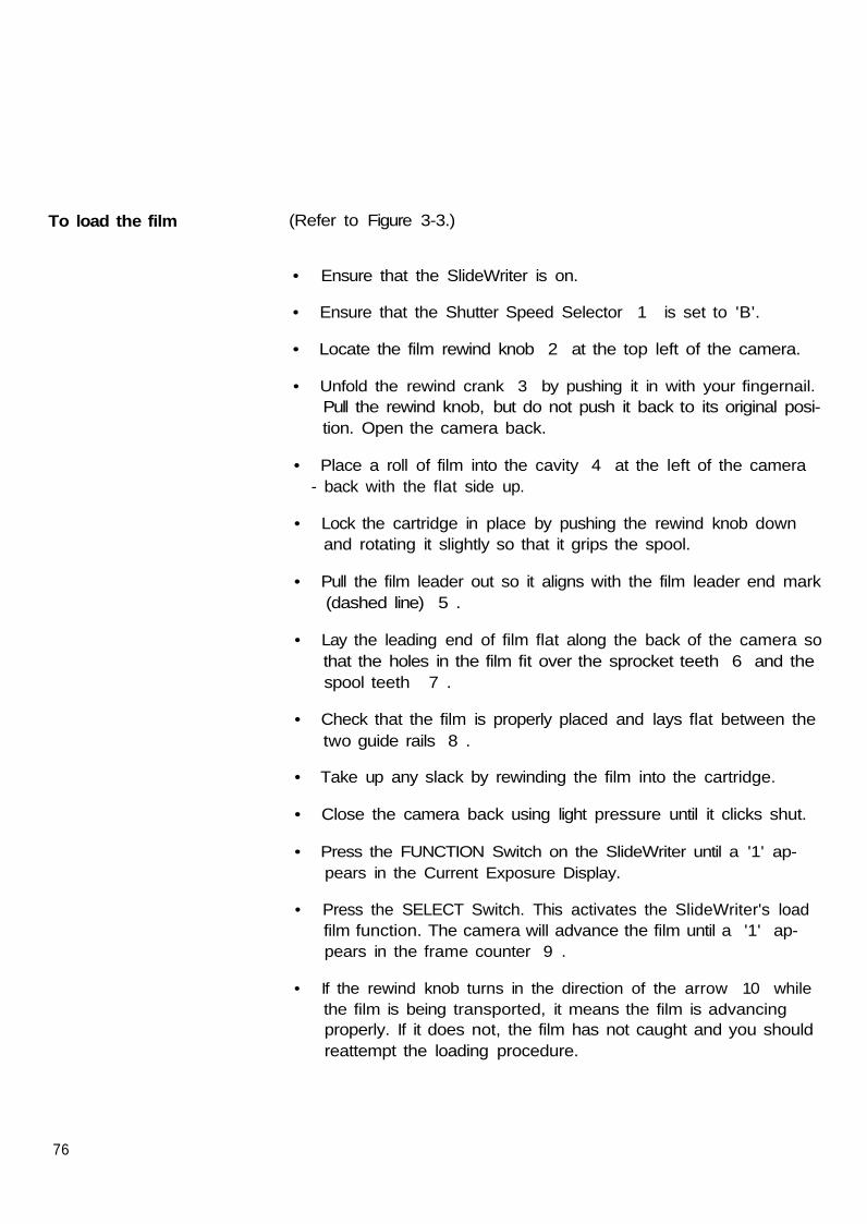
To load the film (Refer to Figure 3-3.)
• Ensure that the SlideWriter is on.
• Ensure that the Shutter Speed Selector 1 is set to 'B'.
• Locate the film rewind knob 2 at the top left of the camera.
• Unfold the rewind crank 3 by pushing it in with your fingernail.Pull the rewind knob, but do not push it back to its original posi-tion. Open the camera back.
• Place a roll of film into the cavity 4 at the left of the camera- back with the flat side up.
• Lock the cartridge in place by pushing the rewind knob downand rotating it slightly so that it grips the spool.
• Pull the film leader out so it aligns with the film leader end mark(dashed line) 5 .
• Lay the leading end of film flat along the back of the camera sothat the holes in the film fit over the sprocket teeth 6 and thespool teeth 7 .
• Check that the film is properly placed and lays flat between thetwo guide rails 8 .
• Take up any slack by rewinding the film into the cartridge.
• Close the camera back using light pressure until it clicks shut.
• Press the FUNCTION Switch on the SlideWriter until a '1' ap-pears in the Current Exposure Display.
• Press the SELECT Switch. This activates the SlideWriter's loadfilm function. The camera will advance the film until a '1' ap-pears in the frame counter 9 .
• If the rewind knob turns in the direction of the arrow 10 whilethe film is being transported, it means the film is advancingproperly. If it does not, the film has not caught and you shouldreattempt the loading procedure.
76

Unloading Film
Figure 3-4. Unloading Film from the Pentax A3000 Camera
When the film advances past the last frame, two dashes ( - - )appear in the Current Exposure Display and the beeper sounds.You should now unload the film in the following way:
• Depress the film rewind button located on the underside of thePentax Camera. If the button does not stay depressed, keep itdepressed until the next step is complete.
• Unfold the rewind crank and turn it in the direction of the arrowindicated in Figure 3-4 until the exposure counter returns to 'S'.
• Open the camera back by pulling up on the rewind knob;
• Remove the film;
• Press the FUNCTION Switch on the SlideWriter until a '2'appears;
• Press the SELECT Switch to execute the unload film sequence.
79

SLIDEWRITER MAINTENANCE
GeneralMaintenance
The SlideWriter is a relatively maintenance-free device. It should bekept as clean, dry, and free from dust as possible.
A non-abrasive household cleaner may be used to remove dust andscuff marks from the outside panels. Avoid getting any foreignsubstances near the Pentax Camera.
Test Operations The SlideWriter operation can be tested at any time by running atest pattern without film (Functions 6 and 7) or with film (Functions 8and 9) to test the unit's brightness calibration, focus, and otherimaging characteristics. The following text provides directions forrunning these tests.
NOTE: Do not attempt to run test patterns while the SlideWriter is activelycontrolled by the host computer. Local test patterns will interfere withthe SlideWriter remote activities. Neither the FAULT light nor theERROR light should be on.
20
Running a Test Pattern A test pattern can be run without exposing an image on film. OpenWithout Film the back of the Pentax Camera and observe the filter wheel. It(No Exposure) should rotate to position each colored filter in front of the Pentax
Camera for exposure. (Refer to Figure 5-1.)
• Press the FUNCTION Switch on the Display Panel, holding it downuntil the function number desired, either 6 or 7, appears in theCurrent Exposure Display. (The CRT will display test pattern A whenFunction 6 is selected, test pattern B when Function 7 is selected.)
• Press the SELECT Switch. This executes the chosen function. Theprocess takes approximately 3 to 4 minutes for 2k patterns, and upto 15 minutes for 4k patterns depending on the SlideWriter setting(2k is the default test pattern mode unless the host sends a priorresolution setting command).
If the pattern finishes without the ERROR or FAULT lights turning on,the SlideWriter is working properly.
WARNING Do not press the FUNCTION and SELECT Switches simultaneously.This causes the SlideWriter to activate a diagnostics routine At thistime "dr" will appear in the Current Exposure Display. Press theRESET Switch to return the SlideWriter to normal operation.
Diagnostic routines are to be performed only by trained, qualifiedservice personnel. Initiating a diagnostics routine risks potentialdamage to the SlideWriter and voids warranties made by Matrix.
*
NOTE: If an ERROR or FAULT light remains on, check the error code in theCurrent Exposure Display and refer to page 34 to identify theproblem. Then reset the SlideWriter and try the test image again. Ifthis problem persists, contact your authorized Matrix servicerepresentative.
21

Running a Test PatternWith Film(With Exposure)
Test Pattern 0 (Function 8)
Test Pattern 1 (Function 9)
Load film according to the instructions in Chapter 3.
Press the FUNCTION Switch on the Display Panel, holding itdown until the desired function, either 8 or 9, appears in theCurrent Exposure Display.
Press the SELECT Switch to execute the function chosen. Theprocess takes approximately 3 to 4 minutes for 2k patterns, and|up to 15 minutes for 4k patterns depending on the SlideWritersetting (2k default or software specified).
• Compare the test pattern with the equivalent factory test patternreceived with the SlideWriter.
Verifies focus, proper geometric and radiometric registration, colorregistration, and color balance. In each colored or neutral section,three subsections contain patterns of exposed and unexposed pixels(pixel-on/pixel/off patterns).
Verifies linearity, focus, and color registration. It appears as auniform field of neutral 16-pixel squares on a dark background. Theneutral squares in this image are produced from three passes, thatis, from light passed through all three color filters.
Upon pattern completion, the READY light will come on and abeeping tone will sound.

REFERENCE
System Description
Components of SlideWriter The SlideWriter receives files of rasterized image data from the hostcomputer. The SlideWriter uses this data to produce high resolution
35mm slides.
Figure 5-1. SlideWriter Major Components
The SlideWriter film recorder consists of the following components:
A Display Panel with Input Switches;
A monochrome Cathode Ray Tube (CRT) which acts as the lightsource for film exposure;
A color filter wheel which positions one of four filters (red,green, blue, or neutral) across the optical path;
A 35mm camera which exposes the film to the CRT image andautomatically advances the film;
A power supply; and
A microprocessor, memory, and associated circuitry.
23

Figure 5-2. SlideWriter Imaging Process
The SlideWriter's microprocessor decodes input data received fromthe host through an SCSI interface cable and controls the CRT beampath and intensity. The CRT produces up to 256 different shades ofgray which, when combined after the three color passes, canproduce a maximum of 16.7 million colors.
The microprocessor rotates the filter wheel, controls the camerashutter, and advances the film. The display control indicatesinformation on the Display Panel and accepts operator input via itspanel switches.
The CRT images the computer-generated data in the form of atraveling spot of light. The filter wheel electronically selects the colorfilter that the light will pass through and a lens focuses the light onthe film. The shutter in the film back opens to allow film exposure.
Images are created by exposing the film to each resolvable locationalong the scan line for the amount of time per color as specified bythe incoming data.
After completing a color pass, the filter wheel rotates and theprocess repeats until each of the three primary colors (red, green,and blue) has been recorded.
The SlideWriter digital film recorder utilizes a time-modulated filmrecording process. This means that the light intensity of the CRT'selectron beam remains constant for each pixel exposure while theamount of time spent on recording each pixel varies. The result isvery consistent spot size and color balance.
24

Power-up andSystem Reset
Power Up
System Reset
Upon power-up, the SlideWriter:
• Executes a warm-up;• Diagnosis the system memory;• Executes a system reset;• Performs a calibration of assigned brightness levels; and• Programs the two consecutive addresses specified by the
display board DIP Switch, into the SCSI controller.
As well as during power-up, a system reset occurs in the followingcircumstances:
• Pressing the SlideWriter RESET Switch;
• The SlideWriter receives a BUS RESET signal from the hostcomputer via the SCSI interface;
• After the SlideWriter receives a REQUEST SENSE command toclear a fault or an error condition;
• After the SlideWriter receives a Select Resolution with Resetcommand.
Upon a system reset the SlideWriter will perform the following:
• Turns off all display lights;
• Loads the delay time constant with zero;
» Turns off and centers the CRT beam;
• Rotates the filter wheel to the neutral filter position;
• Sounds the alarm beeps for 1/2 second;
• Turns the READY light on to indicate that the SlideWriter isoperational;
• Loads default image dimensions (2048 pixels/line x 1366 scanlines for 2k, 4096 pixels/ line x 2732 scan lines for 4k);
(continued)
25

• Enables automatic calibration (if disabled);
• Enables automatic camera control (if disabled);
• Enables automatic filter wheel control (if disabled);
• Enables end of image warble signal (if disabled);
• Enables black jumping (if disabled);
• Disables 90 degree rotation (if enabled);
• Disables exchange of coordinates (if enabled);
• Disables mirror imaging (if enabled);
• Disables 180 degree rotation (if enabled);
• Interrupts current command in progress;
The SlideWriter requires several seconds to complete a systemreset, due to the time it takes to rotate the filter wheel. Do notissue any commands until a reset has had time to complete. TheREADY light will go on after a reset is complete.
26
Function Numbers
To choose a function
Pressing the FUNCTION Switch accesses a number of functionswhich the SlideWriter performs in order to execute pre-setinstructions.
• Press the FUNCTION Switch while in the ready state.
• Hold the FUNCTION Switch. Notice that the two-digit reading inthe Current Exposure Display will increase.
• When the function number desired appears, release theFUNCTION Switch and press the SELECT Switch to indicate thechoice. The SlideWriter will then execute the function.
WARNING Do not press the FUNCTION and SELECT Switches simultane-ously. This causes the SlideWriter to activate a diagnostics rou-tine. At this time "dr" will appear in the Current Exposure Dis-play. Press the RESET Switch to return the SlideWriter to normaloperation.
D i a g n o s t i c routines are to be performed only by trained, qualifiedservice personnel. Initiating a diagnostics routine risks potentialdamage to the SlideWriter and voids warranties made by Matrix.
For most functions, the SlideWriter will execute the desired functionsequence then return to normal operation. However, somefunctions, such as 5 and 10, require that another choice (an SCSIaddress or a frame count) to be made. In these cases, perform theabove steps again. Remember that the task is not completed untilthe READY light comes back on.
27

FunctionNumbers
1234567891011
Function Description
Load filmUnload filmDisable automatic calibrationCalibrate to assigned intensitiesSet SCSI addressesTest pattern 0, no exposureTest pattern 1 , no exposureTest pattern 0 with exposureTest pattern 1 with exposureSet frame counterEnable automatic calibration
Table 5-1. Numbered SlideWriter functions
Choose the function number that corresponds to the functiondesired.
The SlideWriter can perform the following functions:
1 - Load Film Select this function after loading film into the camera. It causes theSlideWriter to;
• Clear the "end-of-film" and "no film" flags;• Set the "film present" flag; |• Move the film ahead to the first frame, and• Set the frame counter to one.
2 - Unload Film This function causes the SlideWriter to ;
• Reset the end-of-film condition;• Reset the "film present" flag;• Set the frame counter to zero. (The Display Window
will show two dashes.)
28

3 - Disable AutomaticCalibration
4 - Calibrate to AssignedIntensities
5 - Set the SCSI DeviceAddresses:
CAUTION
This function causes the SlideWriter to turn off automaticcalibration between exposures.
Automatic calibration mode causes the SlideWriter to re-calibratethe CRT's brightness levels automatically between images. Thisensures a high standard of accuracy in image brightness, but takestime that this function can save.
This function causes the RED, GREEN, and BLUE lights to flash for afew seconds while the SlideWriter calibrates. The SlideWriter willcalibrate only certain assigned levels in order to reduce the amountof time consumed by the process.
The function lets the operator set up the SlideWriter device addresson the SCSI interface to the host computer. On power up, theSlideWriter reads a default address from the DIP Switches inside theDisplay Panel. Upon selecting this function, the current deviceaddress will appear in the Current Exposure Display. To leave this asthe active address, press the SELECT Switch. Press the FUNCTIONSwitch to increase the current address in steps of one up to "6"(after "6" the display goes to zero and repeats the process). PressSELECT to indicate the address desired.
The SlideWriter will not operate remotely from the host computerunless it's SCSI address corresponds to the address programmed bythe host (refer to page 32 for additional information.)
29

6, 7, 8, 9 - Test Patterns: The SlideWriter comes with copies of two test patterns which itstores internally and can output on request. (There is moreinformation on test patterns in Chapter 4.) Either pattern will takeapproximately three minutes to image in 2k mode, longer in 4kmode., The SlideWriter will beep four times when it is finished. Thefunctions are as follows;
6 The CRT will display test pattern 0 but the shutter will remain closedduring imaging.
7 The CRT will display test pattern 1 but the shutter will remain closedduring imaging.
8 The SlideWriter will expose test pattern 0 on film.
9 The SlideWriter will expose test pattern 1 on film.
10 - Set Frame Counter: After selecting function 10, press FUNCTION again to increase theframe count in steps of one. Press SELECT to:
• Set the frame count to the displayed value, andReset the end-of-film condition.
11 - Enable AutomaticCalibration
This function activates automatic calibration.
30

The SlideWriterBeeper The SlideWriter contains a beeper that alerts the operator to various
conditions with different kinds of beeps. The following is a list of thetype (solid or warbled) and length of beeps, and why they occur:
• A solid one-half second beep indicates the completion of ahardware reset and power-up ready.
• A solid one-half second beep indicates an increase in functionselection.
• Four short beeps indicate that the SlideWriter has successfullyI " recorded an image.
• A continuous repeating beep approximately once per second, theCurrent Exposure display flashing once per second, and a rod LEDon the camera indicate that the SlideWriter is out of film. Refer topage 19 of this manual to unload the film.
» A warbled beep for two seconds indicates an error. The beeperwill emit a warbled sound approximately every fifteen seconds. Thealarm will stop when the RESET Switch is pressed or send aREQUEST SENSE command from the initiator or host.
31

Programming the SCSI Device Address
The Small ComputerSystems Interface(SCSI)
The Small Computer Systems Interface (SCSI) Device Addressdesignates a specific location or destination of information. Duringmanufacturing, the SlideWriter's Device Address is preset (defaultsettings) using DIP switches as part of the SlideWriter'scommunication protocol with the host processor.
The SCSI default address is set to 2 (See Table 5-2.)
Verify the SCSI address setting by selecting Function 5 (describedon the following page). The current address will appear in theCurrent Exposure Display.
The default settings may be altered in the following way:
• Turn off the SlideWriter. Re-setting the DIP switches does notaffect the SlideWriter until the next power-up, so the unit should beoff when the settings are changed.
• Lift up the left edge of the black plastic strip just beneath theDisplay Panel by carefully using a small screwdriver. This strip is thesame width as the Display Panel by about one inch high andadheres with velcro.
• Pull the left edge of the strip outward far enough to locate theDIP Switch underneath. When received, it is set to "00010". ("0" isoff, or down, and "1" is on, or up.) Switches 1, 2, and 3 are usedto set the Device Address.
Figure 5-3. Location of the SCSI DIP Switch
32

• Set the switches to represent the desired address in binary bypressing the appropriate bit until it clicks. Use the tip of a pen or asmall flat tip screwdriver. The switch is off (0, zero) when the top ofthe switch is pushed in. The switch is on (1, one) when the bottomof the switch is pushed in.
NOTE: SCSI address 7 is reserved for the host. Do not set the SCSI DIPSwitch to 00111 (7). This will cause Error Code "86" to appear.Refer to page 34 for Error Code explanations.
• Replace the plastic strip and turn on the SlideWriter. Themicroprocessor will read the DIP Switch and program the .SlideWriteraddresses.
To select addresses other than the DIP-determined defaults, selectfunction number 5 while the SlideWriter is running.
To do this:
• Press the FUNCTION Switch on the Display Panel, holding it downuntil the number "5" appears in the Current Exposure Display.
• Press the SELECT Switch. An even number between 0 and 6 willappear, representing the current SCSI address. After "6" the displaygoes to zero and repeats the process.
• Press the FUNCTION Switch again. The number displayed willincrease by one. Press the FUNCTION Switch as many times asnecessary to reach the desired value.
• Press the SELECT Switch to set this value.
5,4
00000000
SCSI DIP Switch
3
00001111
2
00110011
1
01010101
SCSI ID
0123456*
SCSI Address 7 Is reserved for the host, and may not be used by the SlideWriterOn the Device Address DIP Switch, 0 is the OFF position and 1 Is the ON position
Table 5-2. Device Address Settings
33

SlideWriter Error CodesError codes are intended as a guide to the operator or programmer.Even though the SlideWriter has an extensive set of error codes, donot attempt a form of automatic error recovery. In most instances,and error code means that the SlideWriter has exposed incorrectinformation on film.
When the SlideWriter detects an error, it reports the error byilluminating the ERROR or FAULT lights and displays an error codein hexadecimal on the current Exposure Display referred to as a"primary error code". The following table explains the primary errorcodes:
Primary Code
838486919293A2
Problem
Illegal CommandIllegal Data ByteIllegal SCSI AddressMemory FaultSCSI Interface FaultCRT Beam Calibration FaultFilter Wheel Fault
Table 5-3. Primary Error and Fault Code Interpretations
When an error or fault occurs, the SlideWriter emits a warbled beepevery 15 seconds. During the 15 second interval between warbledbeeps, and before the host processor sends a REQUEST SENSEcommand, press the FUNCTION Switch to display a secondary errorcode on the Current Exposure Display.
After having displayed the secondary error code, display thecontents of the SlideWriter's internal registers to obtain even moreinformation This is accomplished by pressing the SELECT Switch.The SlideWriter displays the registers in the following order: H, L, D,E, B, C. After the SlideWriter displays register C, press theFUNCTION Switch to return the SlideWriter to the primary errordisplay.
34

Explanation ofError Codes
Primary Code: 83
Primary Code: 84
Incorrect camera operation, incorrect data from the computer, ormalfunctions of the SlideWriter can result in errors and faults. Ifthere is an error or fault due to SlideWriter malfunctioning, note theprimary and secondary error codes and the values of all registers.Then call your Matrix service representative.
The following explanation describes the problems which cause anerror message and the primary and secondary codes.
Problem: Illegal CommandSecondary Code: 00, 01Reason for Error: While the SlideWriter was in the idle state, itreceived an unrecognized command. The illegal command byte iscontained in register "H".Secondary Code: 02Reason for Error: The SlideWriter received a command with an illegalparameter. The command byte is contained in register "H", and theillegal parameter is contained in register "L".
Problem: Illegal Data Byte
Secondary Code: 01Reason for Error: The SlideWriter received and illegal run-lengthcode (a length of zero). This code is contained in register "E", andindicates a special function. The function code (INTENSITY) does notcorrespond to any of the allowed codes. Function codes arecontained in register "C".Secondary Codes: 02, 03, 04• 02 indicates that the initial horizontal address was greater thanthe allowed minimum.
• 03 indicates that the calculated end address was greater thanthe allowed maximum.
• 04 indicates that the calculated end address was less than thestart address.For all three errors
• H and L contain the horizontal start address,• D and E contain the end address, and• B and C contain the pixel count.
35
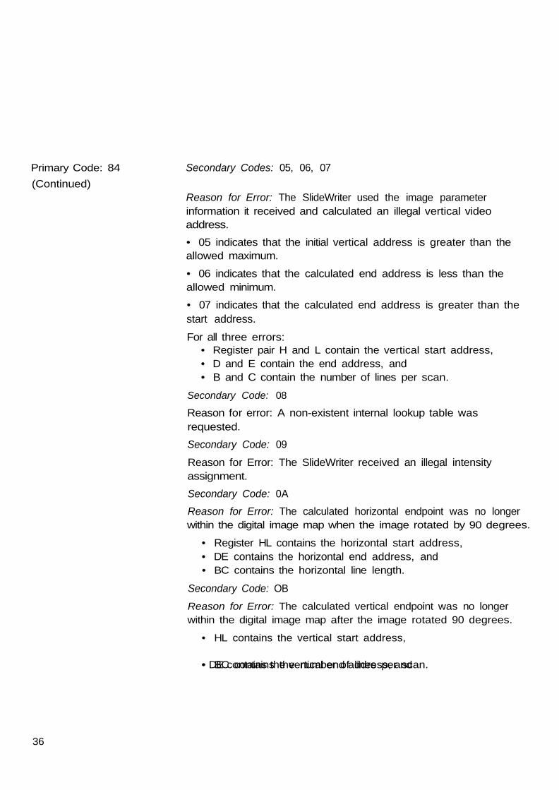
Primary Code: 84(Continued)
Secondary Codes: 05, 06, 07
Reason for Error: The SlideWriter used the image parameterinformation it received and calculated an illegal vertical videoaddress.• 05 indicates that the initial vertical address is greater than theallowed maximum.• 06 indicates that the calculated end address is less than theallowed minimum.
• 07 indicates that the calculated end address is greater than thestart address.For all three errors:
• Register pair H and L contain the vertical start address,• D and E contain the end address, and• B and C contain the number of lines per scan.
Secondary Code: 08
Reason for error: A non-existent internal lookup table wasrequested.Secondary Code: 09Reason for Error: The SlideWriter received an illegal intensityassignment.Secondary Code: 0AReason for Error: The calculated horizontal endpoint was no longerwithin the digital image map when the image rotated by 90 degrees.
• Register HL contains the horizontal start address,• DE contains the horizontal end address, and• BC contains the horizontal line length.
Secondary Code: OBReason for Error: The calculated vertical endpoint was no longerwithin the digital image map after the image rotated 90 degrees.
• HL contains the vertical start address,
• DE contains the vertical end address, and• BC contains the number of lines per scan.
36
Primary Code: 86
Primary Code: 91
Primary Code: 92
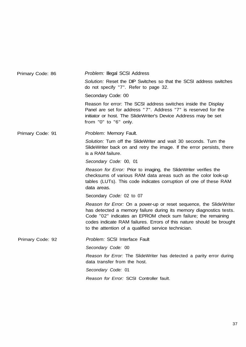
Problem: Illegal SCSI AddressSolution: Reset the DIP Switches so that the SCSI address switchesdo not specify "7". Refer to page 32.
Secondary Code: 00
Reason for error: The SCSI address switches inside the DisplayPanel are set for address " 7". Address "7" is reserved for theinitiator or host. The SlideWriter's Device Address may be setfrom "0" to "6" only.
Problem: Memory Fault.
Solution: Turn off the SlideWriter and wait 30 seconds. Turn theSlideWriter back on and retry the image. If the error persists, thereis a RAM failure.
Secondary Code: 00, 01
Reason for Error: Prior to imaging, the SlideWriter verifies thechecksums of various RAM data areas such as the color look-uptables (LUTs). This code indicates corruption of one of these RAMdata areas.
Secondary Code: 02 to 07
Reason for Error: On a power-up or reset sequence, the SlideWriterhas detected a memory failure during its memory diagnostics tests.Code "02" indicates an EPROM check sum failure; the remainingcodes indicate RAM failures. Errors of this nature should be broughtto the attention of a qualified service technician.
Problem: SCSI Interface Fault
Secondary Code: 00
Reason for Error: The SlideWriter has detected a parity error duringdata transfer from the host.
Secondary Code: 01
Reason for Error: SCSI Controller fault.
37

Primary Code: 93
Primary Code: A2
Problem: CRT Beam Calibration Fault
Secondary Code: 00, 01
Reason for Error: Code "00" the CRT beam is too bright. Code "01"the CRT beam is too dim. If the SlideWriter is unable to maintainproper CRT intensity, contact your Matrix service representative.
Problem: Filter Wheel Fault
Secondary Code: 00 to 05
Reason for Error: The SlideWriter is experiencing problems in reliablymoving the filter wheel.
38

Setting the SlideWriter asan Unterminated SCSI Device.
CAUTION This procedure is intended for qualified service personnel only. Thereare no user servicable parts or adjustments in the SlideWriter.
If you intend to locate the SlideWriter in the middle of the SCSI busas indicated in Chapter 2, Figure 2-6, then you must remove theSlideWriter's internal SCSI terminators. The terminators are resistorpacks U1 and U2 on the SlideWriter's Processor Board. Theobjective of the following procedure is to carefully remove U1 andU2 from their respective DIP sockets on the Processor Board.
Figure 5-4. Side Cover Removal
Side Cover Removal Remove the side cover by performing the following procedure.
• Turn the SlideWriter off and disconnect the line cord and SCSIcable (s). Lay the unit on its side so that the camera back is on theleft side and faces away form you. Ensure that you lay the unit on aflat, level surface. See the above illustration for correct positioning.
• Remove the slotted screw near the Power and Signal Input Panel.
• Carefully pull the side cover off and store it in a safe place. Thisgives you general access to all interior PC boards, power suppliesand the CRT assembly.
39

Terminator ChipRemoval Procedure In order to gain access to the Processor Board you must remove
the Low Voltage Power Supply. You do not need to disconnect theAC or DC power connectors because you will only move the PowerSupply module to another spot. You will not remove it entirely fromthe unit.
Figure 5-5. Low Voltage Power Supply Removal
Remove the Low Voltage Power Supply by performing the followingprocedure.
• Remove the four flat-head screws and flat washers that securethe Low Voltage Power Supply to the unit. Save all hardware.
• Remove the P8 Connector from the Processor Board.
» Slide the low voltage power supply partially out of the unit andrest it on the CRT plate. You now have service access to theProcessor Board.
• Terminator Chips U1 and U2 are located next to the 50 pin SCSIribbon cable J1 on the Processor Board. Carefully remove both U1and U2 using an IC extractor or a small flat tip screwdriver.
• Save both terminator chips in case you decide to place theSlideWriter at the end of the device chain at some later date.
40

Replace the low voltage power supply by performing the followingprocedure.
• Position the Power Supply module in the unit and connect ribboncable P8 on the Processor Board.
• Secure the Power Supply module by replacing the four flat-headscrews and flat washers that you removed previously.
Replace the Side Cover as follows:
• Position the cover, matching the velcro-like fasteners, andreplace the slotted screw.
• Turn the SlideWriter upright and connect the line cord and SCSIcables. Refer to page 12 for instructions on connecting theSlideWriter to the SCSI bus.
41

GLOSSARY OF TERMS
This glossary provides the meanings of terms for the purposes of using and programming theSlideWriter. These meanings may not coincide with other uses or with formal definitions.
Black-jumping -
Brightness Level -
Bus -
Cathode Ray Tube (CRT) -
Checksum -
DIP Switch -
DRAM -(Dynamic Random AccessMemory)
Error -
Fault -
Filter Wheel -
An imaging mode in which the CRT Beam skips over black pixels.
One of nine CRT intensities (0 through 8). The user or the internalsystem assigns a subset of intensities to red, green, and blue colorsin a given mode.
A circuit over which information passes.
A vacuum tube in which an electron beam, directed at aphosphor-coated glass screen, causes a point on the screen toglow. As magnetic coils deflect the beam, the point of light movesacross the screen. Variations in the intensity of the beam create avisible display on the screen.
During a check, a sum of bits or bytes in a quantity of data ensuringthat the data is accurate.
A set of 5 switches in a plastic box (a "Dual In-line Package" orDIP) which can be set by hand.
A form of memory, continually refreshed, possessing both read andwrite capability. Memory contents are lost when the power is t u rnedoff.
An operator-induced fault, a programming fault, or a datadiscrepancy.
A hardware-induced failure.
A movable wheel containing three color filters and one neutral filterwhich reside in the optical path and which color the imaging beam.
42

Hexadecimal -
Host Computer -
Initiator -
Intensity Calibration -
Least Significant Bit -
Look-up Table (LUT) -
Microprocessor -
Optical Path -
Peripheral Device -
Pixel -
The representation of numbers in the base-16 number system,using the ten digits 0 - 9 and the six letters A through F.
A computer from which the SlideWriter receives image data andcommands via the SCSI Bus.
An SCSI device (usually a host System) that requests an operationto be performed by another SCSI device.
Checking the CRT hardware to ensure it matches the intensity valuefor each of the levels in the brightness table. The SlideWriterautomatically adjusts this intensity value. Calibration may beperformed either automatically or manually. Refer to page 29.
In a binary number, the bit representing the lowest exponent of 2.
A table translating one set of values into another based on a knownrelationship. SlideWriter LUT's compensate for non-linear filmsensitivity. Different LUTs are required to produce similar results ondifferent film types.
The component of the SlideWriter (and of microcomputers) whichperforms logic, computational and control functions.
The path that the light emitted by the CRT follows through the filterwheel and lens to the film.
A peripheral that can be attached to an SCSI device (e.g., Magneticdisk, printer, optical-disk, or magnetic-tape).
Abbreviation for Picture Element. The smallest position into which animage resolves. The term refers to both the smallest definedsegment of a scan line (a unit of width) and to a two-dimensionalscreen area one pixel wide and one line high.
43

Power-up Sequence -
Reset Sequence -
SCSI -
SCSI Device -
Target -
•
A sequence of operations the SlideWriter goes through when theuser turns the power on. The SlideWriter:• Jests its internal Systems;
• Sets all SCSI functions to the idle state;• Performs memory diagnostics, causing a random flashing of the
display lights;• Loads default LUT values, brightness tables, brightness levels; and• Resets the system.
A sequence of operations the SlideWriter goes through when theuser presses the RESET Switch (Refer to page 25 for details).
(Small Computer System Interface) A standard data communicationinterface which allows high speed transmission of data from onedevice to another.
A host computer adapter or a peripheral controller or an intelligentperipheral that can be attached to the SCSI bus.
An SCSI device that performs an operation requested by a host orinitiator.
44
INDEXAccessories ...............................
AC Power Connection ......................
Beeper Description .... . . . . . . . . . . . . . . . . . . . . .
Controls and Connector descriptionsdisplay panel . . . . . . . . . . . . . . . . . . . . . . . . . . . .rear panel . . . . . . . . . . . . . . . . . . . . . . . . . . . . . .
Device Address, setting the .................
Dimensions . . . . . . . . . . . . . . . . . . . . . . . . . . . . . . .
Error Codes , listed . . . . . . . . . . . . . . . . . . . . . . . . .error codes, explained . . . . . . . . . . . . . . . . . . . .
Film Loading35mm Camera Description . . . . . . . . . . . . . . . .film specification . . . . . . . . . . . . . . . . . . . . . . . . .Function number description ... . . . . . . . . . . . .loading procedure . . . . . . . . . . . . . . . . . . . . . . . .unloading procedure .... . . . . . . . . . . . . . . . . . .
Front Panel Light, description . . . . . . . . . . . . . . . .
Functions (Function Numbers)calibrate to assigned intensities (function 4) .disable automatic calibration (function 3) ....enable automatic calibration function .......load film (function 1 ) . . . . . . . . . . . . . . . . . . . . .set frame counter (function 0) . . . . . . . . . . . . .set the SCSI device address ...............test patterns (functions 6, 7, 8, 9) . . . . . . . . .unload film . . . . . . . . . . . . . . . . . . . . . . . . . . . . . .
Functions, selecting . . . . . . . . . . . . . . . . . . . . . . . .
Function Switch . . . . . . . . . . . . . . . . . . . . . . . . . . . .
Glossary . . . . . . . . . . . . . . . . . . . . . . . . . . . . . . . . . .
Illegal Command . . . . . . . . . . . . . . . . . . . . . . . . . . .
Illegal Data Byte . . . . . . . . . . . . . . . . . . . . . . . . . . .
Memory Fault . . . . . . . . . . . . . . . . . . . . . . . . . . . . .
Power Line Connection . . . . . . . . . . . . . . . . . . . . .
Power Up Instructions ......................
1
7
31
46
32
3
3435
1515281619
5
2929302830293028
27
4
42
35
35
37
7
13
*
Power Up Sequence, Internal description ......
Recording Images .........................
Reset Switch ..............................
SCSI Interfacecable part numbers ......................connections to, ..........................setting device address ....................illegal SCSI address . . . . . . . . . . . . . . . . . . . . . .SCSI Interface . . . . . . . . . . . . . . : . . . . . . . . . . . .
Select Switch .............................
Specificationsenvironmental . . . . . . . . . . . . . . . . . . . . . . . . . . .power ..................................space ..................................
System Descriptioncomponent description ...................system overview .........................
System Reset .............................
Terminationstandard termination for installation .......removing SlideWriter's internal termination .
Test Operationstest pattern (no film) ....................test pattern (with film) . . . . . . . . . . . . . . . . . .test pattern 0 . . . . . . . . . . . . . . . . . . . . . . . . . . .test pattern 1 . . . . . . . . . . . . . . . . . . . . . . . . . .
25
18
4
2
323737
5
222
2324
25
1039
21222222
45

This page intentionally left blank
Manual Number 29-53-2001 Version 246