1.1 Anamnesis, Physic Diagnostic - Dr. Donny H. SpJP (Slide)(1)
© 2005 Pearson Prentice Hall
This work is protected by United States copyright laws and is provided solely for the use of instructors in teaching their courses and assessing student learning. Dissemination or sale of any part of this work (including on the World Wide Web) will destroy the integrity of the work and is not permitted. The work and materials from it should never be made available to students except by instructors using the accompanying text in their classes. All recipients of this work are expected to abide by these restrictions and to honor the intended pedagogical purposes and the needs of other instructors who rely on these materials.
Lecture PowerPoint
Chapter 23
Physics: Principles with Applications, 6th edition
Giancoli
Light: Geometric Optics
Units of Chapter 23
• The Ray Model of Light
• Reflection; Image Formed by a Plane Mirror
• Formation of Images by Spherical Mirrors
• Index of Refraction
• Refraction: Snell’s Law
• Total Internal Reflection; Fiber Optics
• Thin Lenses; Ray Tracing
• The Thin Lens Equation; Magnification
• Combinations of Lenses
• Lensmaker’s Equation
Units of Chapter 23
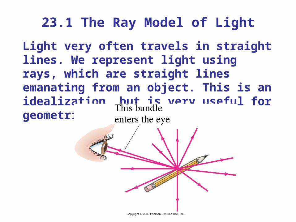
23.1 The Ray Model of LightLight very often travels in straight lines. We represent light using rays, which are straight lines emanating from an object. This is an idealization, but is very useful for geometric optics.
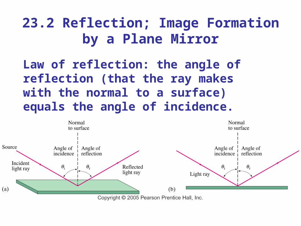
23.2 Reflection; Image Formation by a Plane Mirror
Law of reflection: the angle of reflection (that the ray makes with the normal to a surface) equals the angle of incidence.
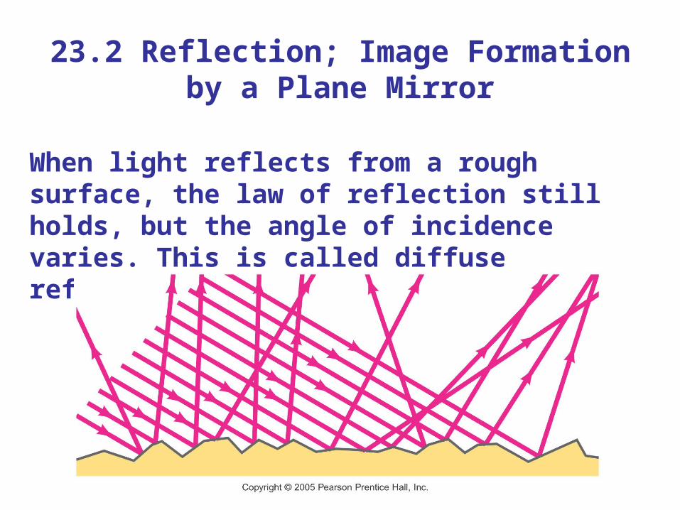
23.2 Reflection; Image Formation by a Plane Mirror
When light reflects from a rough surface, the law of reflection still holds, but the angle of incidence varies. This is called diffuse reflection.
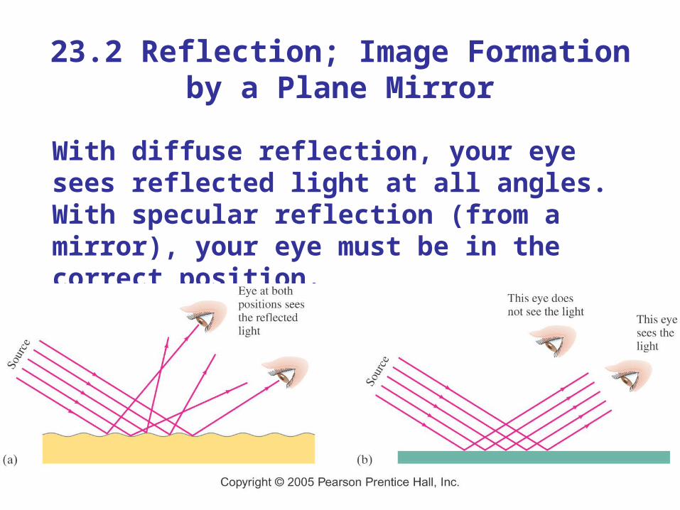
23.2 Reflection; Image Formation by a Plane Mirror
With diffuse reflection, your eye sees reflected light at all angles. With specular reflection (from a mirror), your eye must be in the correct position.
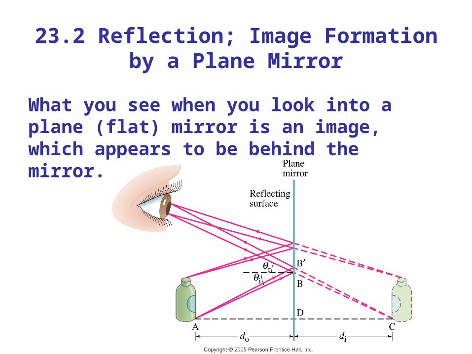
23.2 Reflection; Image Formation by a Plane Mirror
What you see when you look into a plane (flat) mirror is an image, which appears to be behind the mirror.
23.2 Reflection; Image Formation by a Plane Mirror
This is called a virtual image, as the light does not go through it. The distance of the image from the mirror is equal to the distance of the object from the mirror.
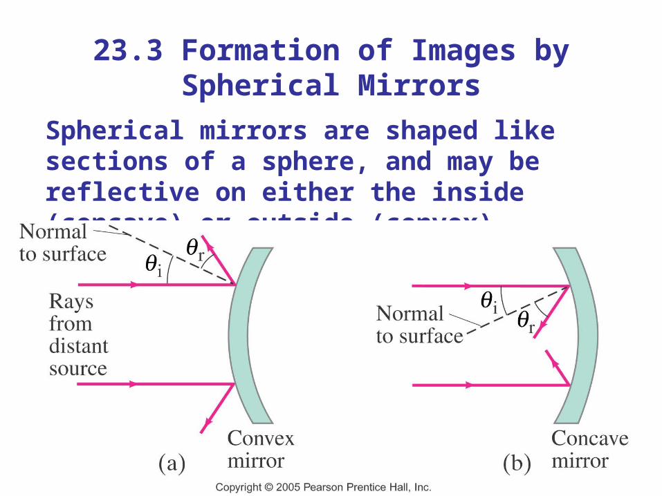
23.3 Formation of Images by Spherical Mirrors
Spherical mirrors are shaped like sections of a sphere, and may be reflective on either the inside (concave) or outside (convex).
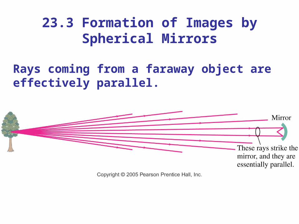
23.3 Formation of Images by Spherical Mirrors
Rays coming from a faraway object are effectively parallel.
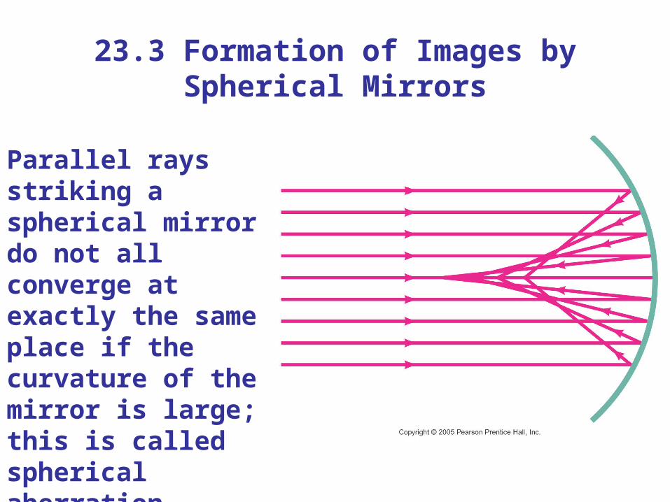
23.3 Formation of Images by Spherical Mirrors
Parallel rays striking a spherical mirror do not all converge at exactly the same place if the curvature of the mirror is large; this is called spherical aberration.
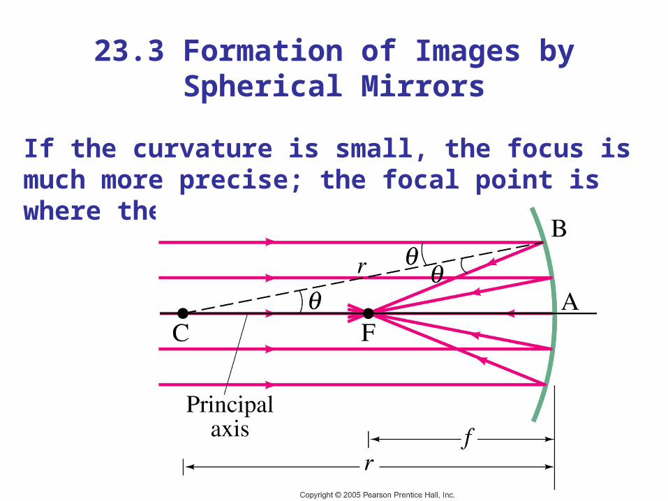
23.3 Formation of Images by Spherical Mirrors
If the curvature is small, the focus is much more precise; the focal point is where the rays converge.
23.3 Formation of Images by Spherical Mirrors
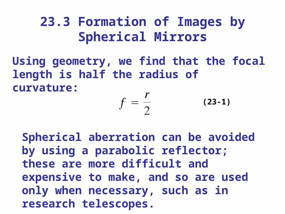
Using geometry, we find that the focal length is half the radius of curvature:
(23-1)
Spherical aberration can be avoided by using a parabolic reflector; these are more difficult and expensive to make, and so are used only when necessary, such as in research telescopes.
23.3 Formation of Images by Spherical Mirrors
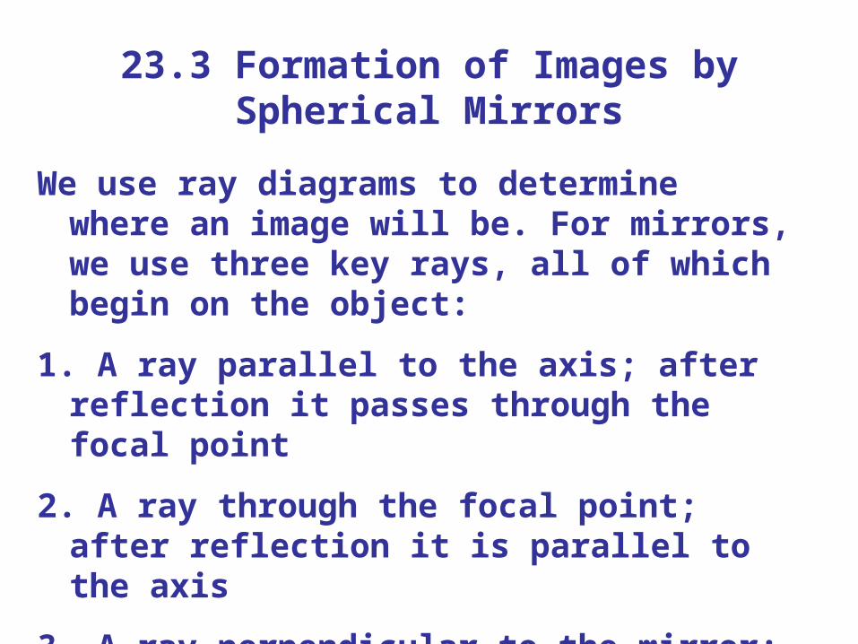
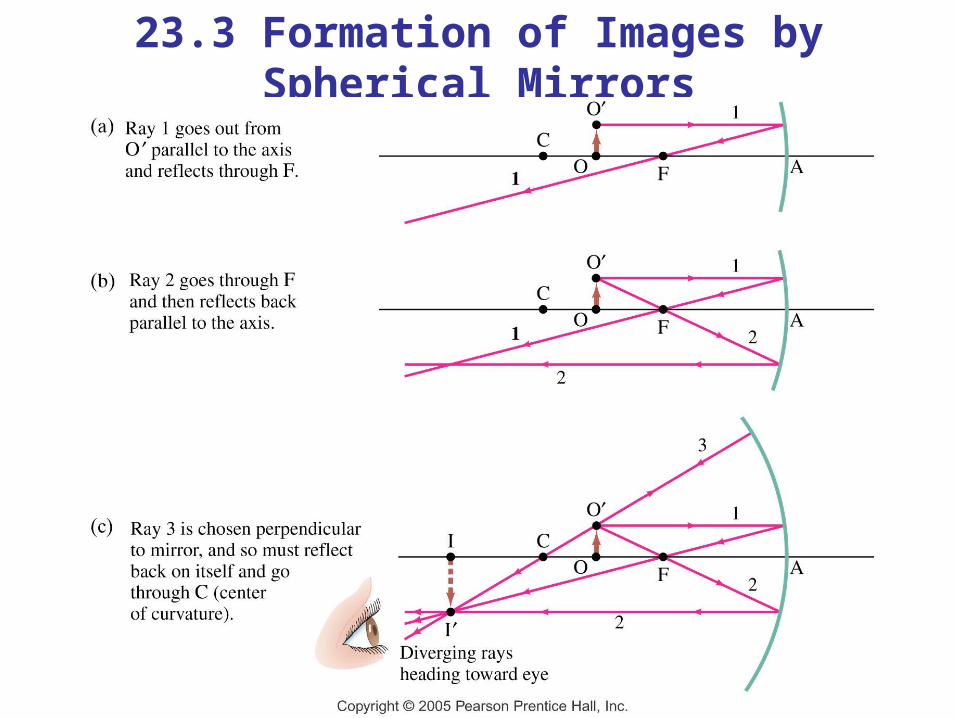
We use ray diagrams to determine where an image will be. For mirrors, we use three key rays, all of which begin on the object:
1. A ray parallel to the axis; after reflection it passes through the focal point
2. A ray through the focal point; after reflection it is parallel to the axis
3. A ray perpendicular to the mirror; it reflects back on itself
23.3 Formation of Images by Spherical Mirrors
23.3 Formation of Images by Spherical Mirrors
The intersection of these three rays gives the position of the image of that point on the object. To get a full image, we can do the same with other points (two points suffice for many purposes).
23.3 Formation of Images by Spherical Mirrors
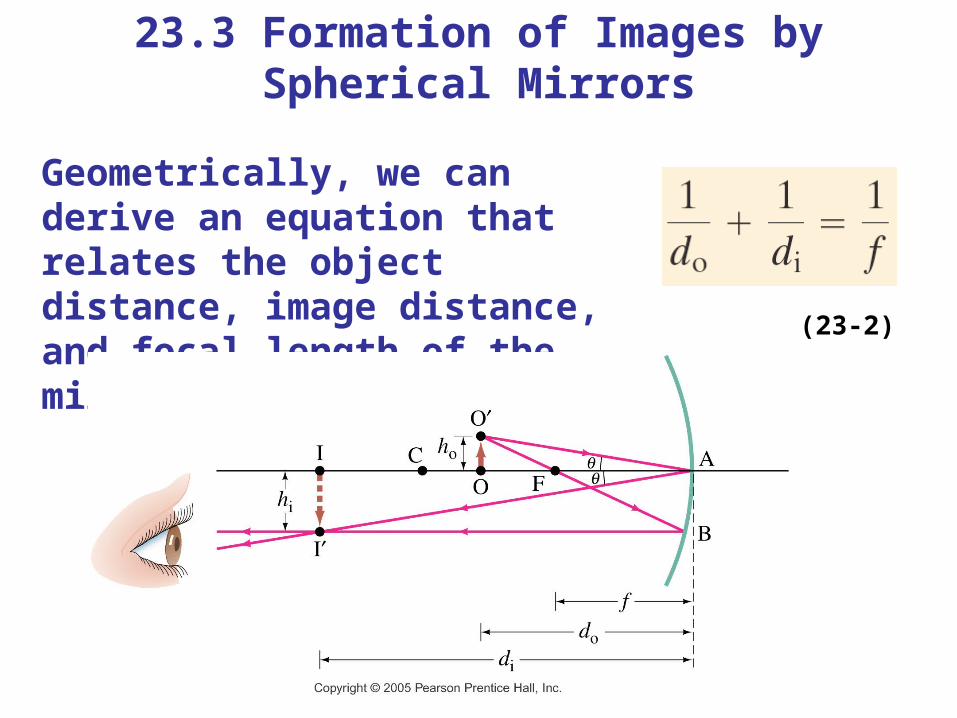
Geometrically, we can derive an equation that relates the object distance, image distance, and focal length of the mirror: (23-2)
23.3 Formation of Images by Spherical Mirrors
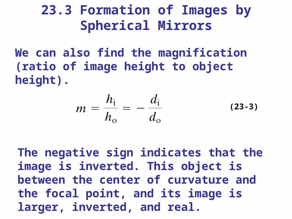
We can also find the magnification (ratio of image height to object height).
(23-3)
The negative sign indicates that the image is inverted. This object is between the center of curvature and the focal point, and its image is larger, inverted, and real.
23.3 Formation of Images by Spherical Mirrors
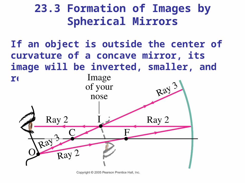
If an object is outside the center of curvature of a concave mirror, its image will be inverted, smaller, and real.
23.3 Formation of Images by Spherical Mirrors
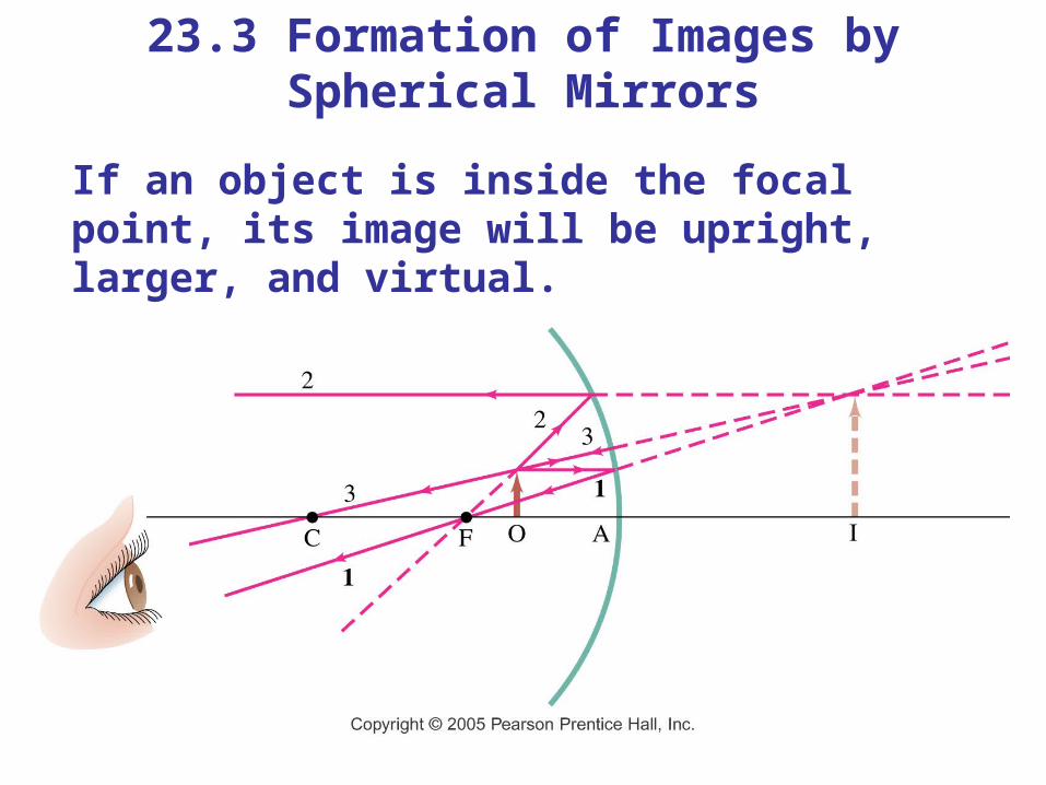
If an object is inside the focal point, its image will be upright, larger, and virtual.
23.3 Formation of Images by Spherical Mirrors
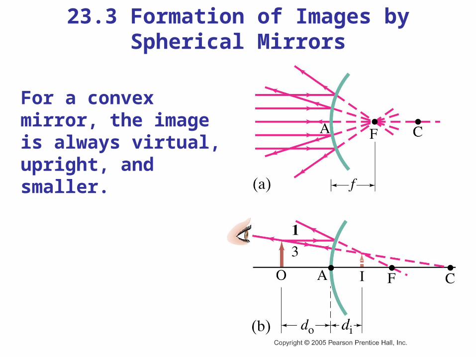
For a convex mirror, the image is always virtual, upright, and smaller.
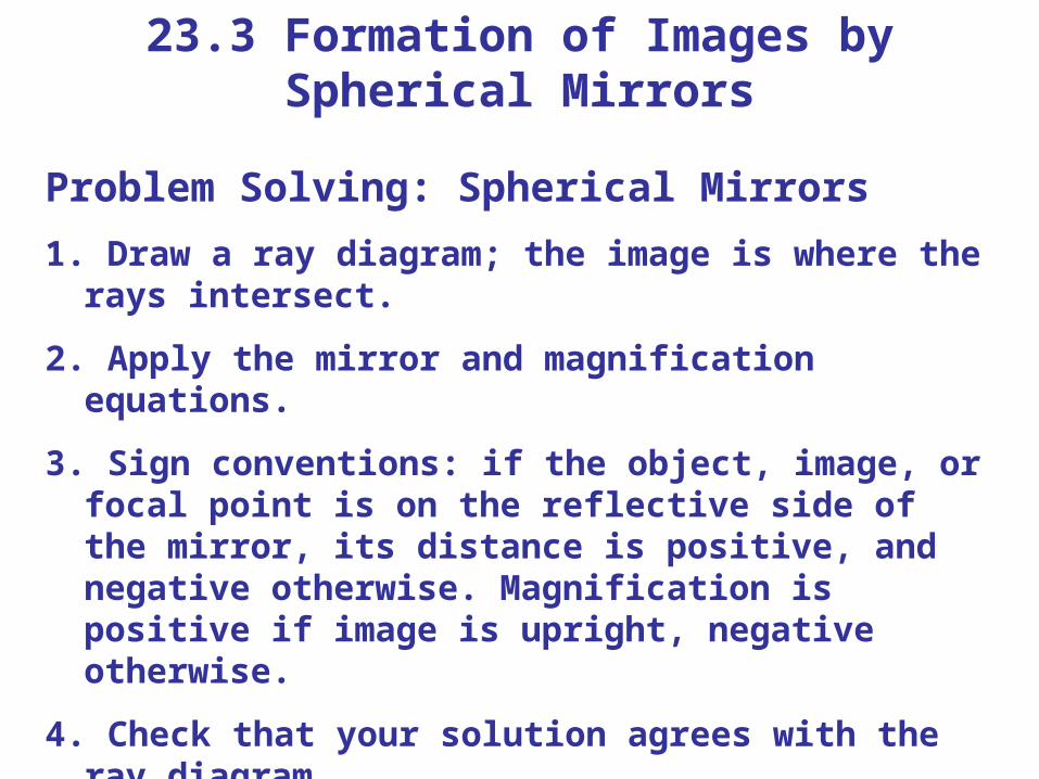
23.3 Formation of Images by Spherical Mirrors
Problem Solving: Spherical Mirrors1. Draw a ray diagram; the image is where the rays
intersect.
2. Apply the mirror and magnification equations.
3. Sign conventions: if the object, image, or focal point is on the reflective side of the mirror, its distance is positive, and negative otherwise. Magnification is positive if image is upright, negative otherwise.
4. Check that your solution agrees with the ray diagram.
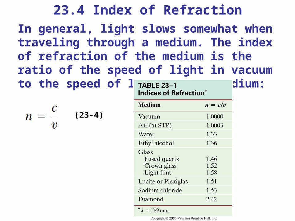
23.4 Index of RefractionIn general, light slows somewhat when traveling through a medium. The index of refraction of the medium is the ratio of the speed of light in vacuum to the speed of light in the medium:
(23-4)
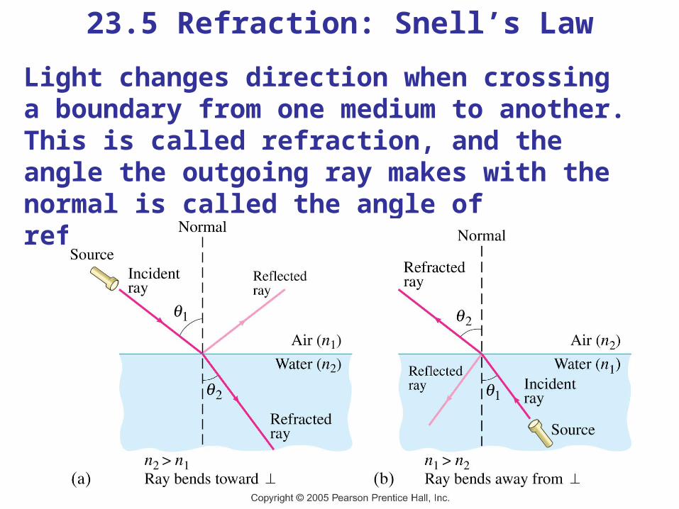
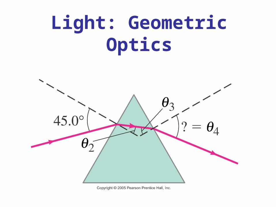
23.5 Refraction: Snell’s LawLight changes direction when crossing a boundary from one medium to another. This is called refraction, and the angle the outgoing ray makes with the normal is called the angle of refraction.
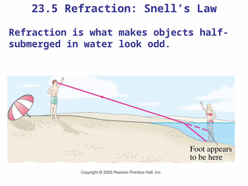
23.5 Refraction: Snell’s Law
Refraction is what makes objects half-submerged in water look odd.
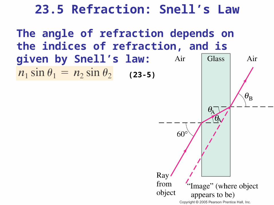
23.5 Refraction: Snell’s Law
The angle of refraction depends on the indices of refraction, and is given by Snell’s law:
(23-5)
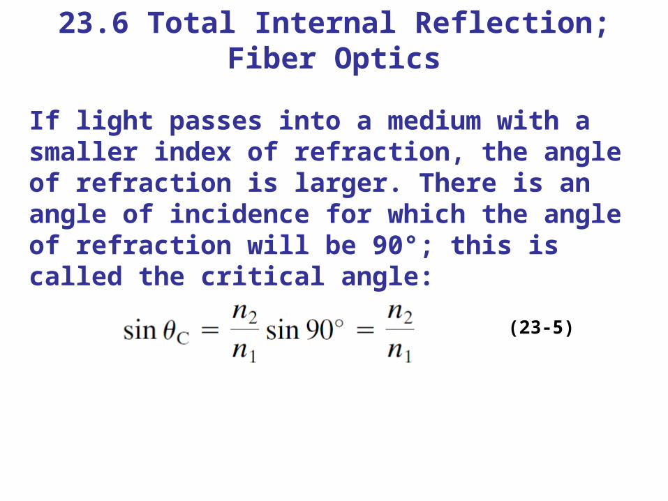
23.6 Total Internal Reflection; Fiber Optics
If light passes into a medium with a smaller index of refraction, the angle of refraction is larger. There is an angle of incidence for which the angle of refraction will be 90°; this is called the critical angle:
(23-5)
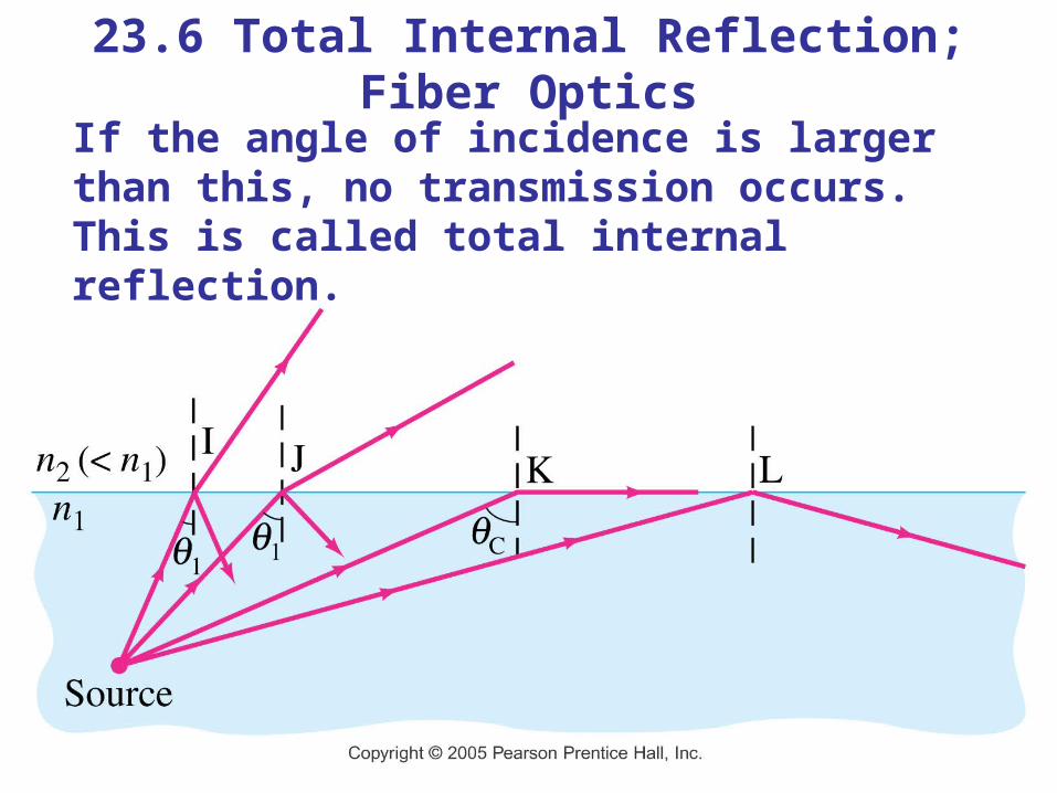
23.6 Total Internal Reflection; Fiber Optics
If the angle of incidence is larger than this, no transmission occurs. This is called total internal reflection.
23.6 Total Internal Reflection; Fiber Optics
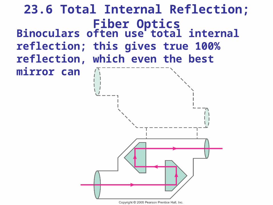
Binoculars often use total internal reflection; this gives true 100% reflection, which even the best mirror cannot do.
23.6 Total Internal Reflection; Fiber Optics
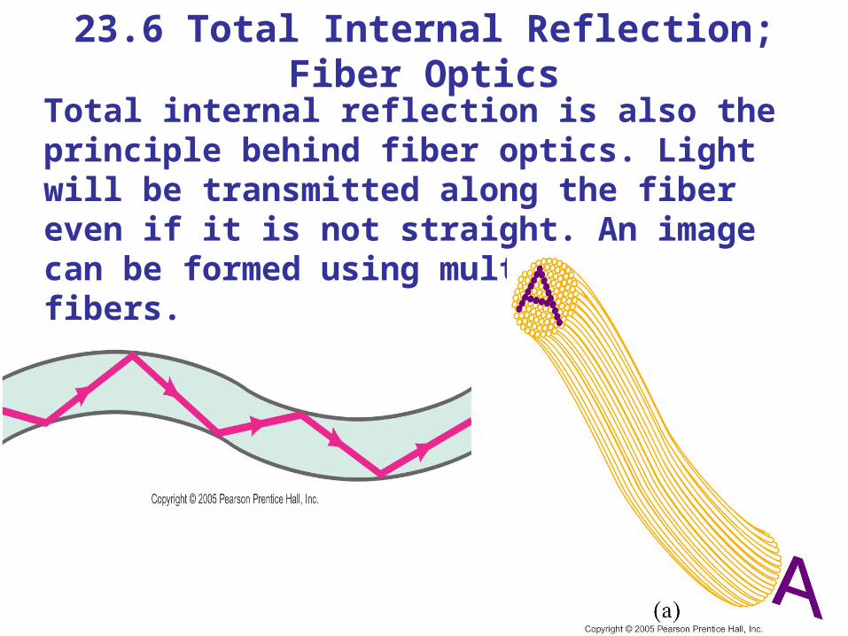
Total internal reflection is also the principle behind fiber optics. Light will be transmitted along the fiber even if it is not straight. An image can be formed using multiple small fibers.
23.7 Thin Lenses; Ray Tracing
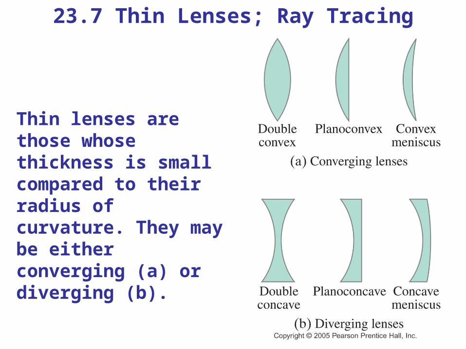
Thin lenses are those whose thickness is small compared to their radius of curvature. They may be either converging (a) or diverging (b).
23.7 Thin Lenses; Ray Tracing
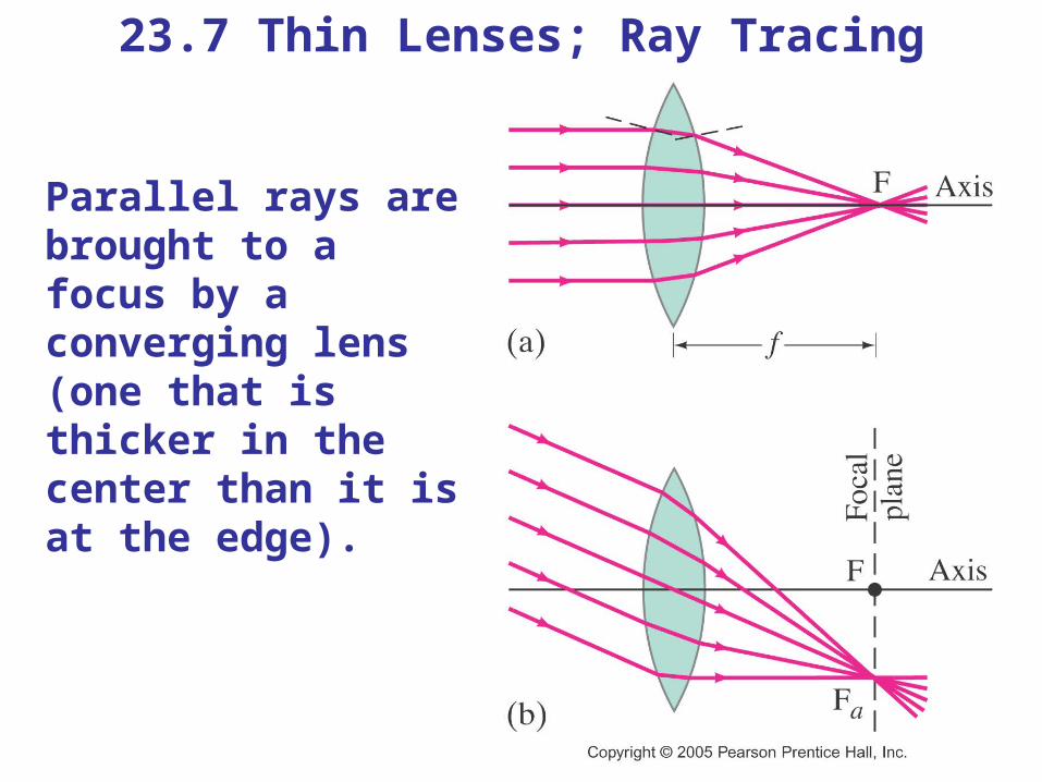
Parallel rays are brought to a focus by a converging lens (one that is thicker in the center than it is at the edge).
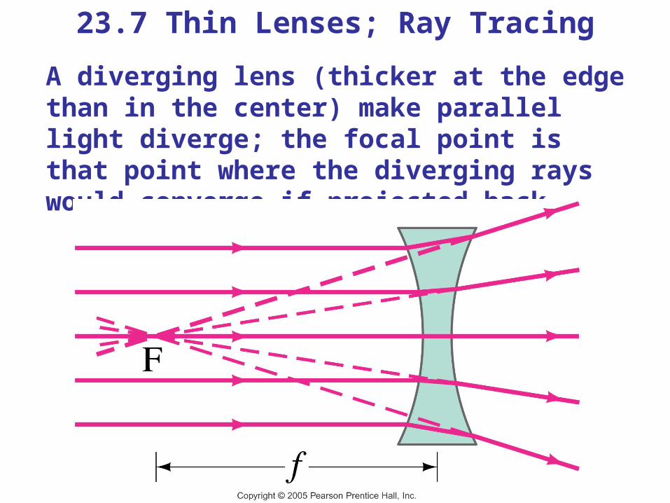
23.7 Thin Lenses; Ray TracingA diverging lens (thicker at the edge than in the center) make parallel light diverge; the focal point is that point where the diverging rays would converge if projected back.
23.7 Thin Lenses; Ray Tracing
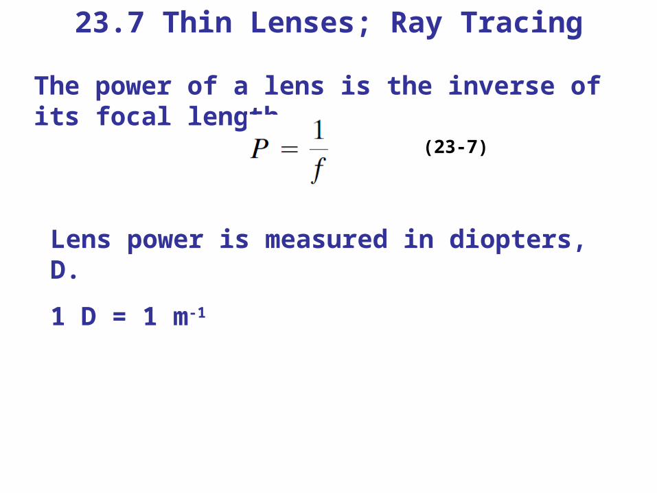
The power of a lens is the inverse of its focal length.
(23-7)
Lens power is measured in diopters, D.
1 D = 1 m-1
23.7 Thin Lenses; Ray Tracing
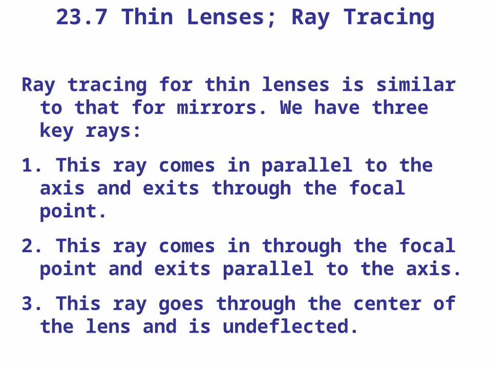
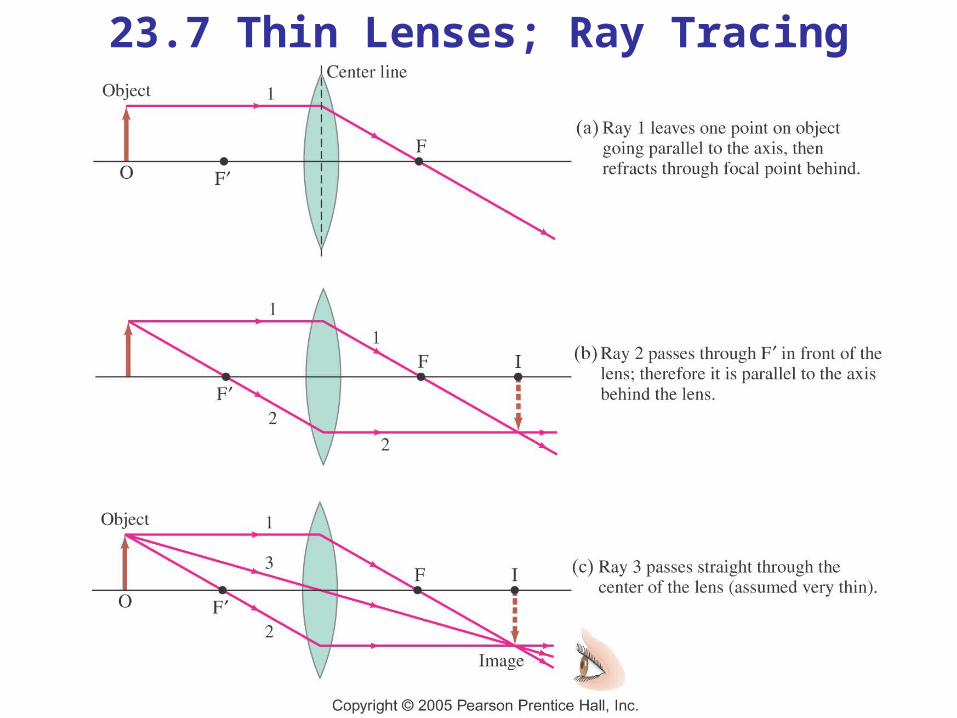
Ray tracing for thin lenses is similar to that for mirrors. We have three key rays:
1. This ray comes in parallel to the axis and exits through the focal point.
2. This ray comes in through the focal point and exits parallel to the axis.
3. This ray goes through the center of the lens and is undeflected.
23.7 Thin Lenses; Ray Tracing
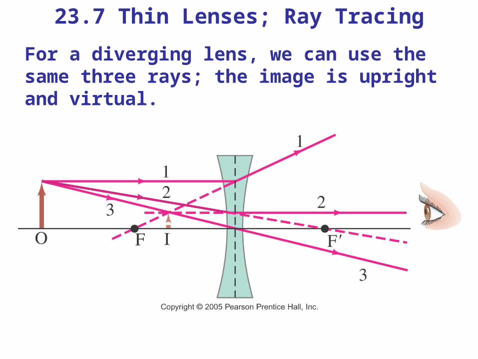
23.7 Thin Lenses; Ray TracingFor a diverging lens, we can use the same three rays; the image is upright and virtual.
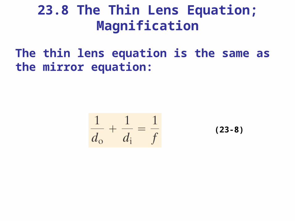
23.8 The Thin Lens Equation; Magnification
The thin lens equation is the same as the mirror equation:
(23-8)
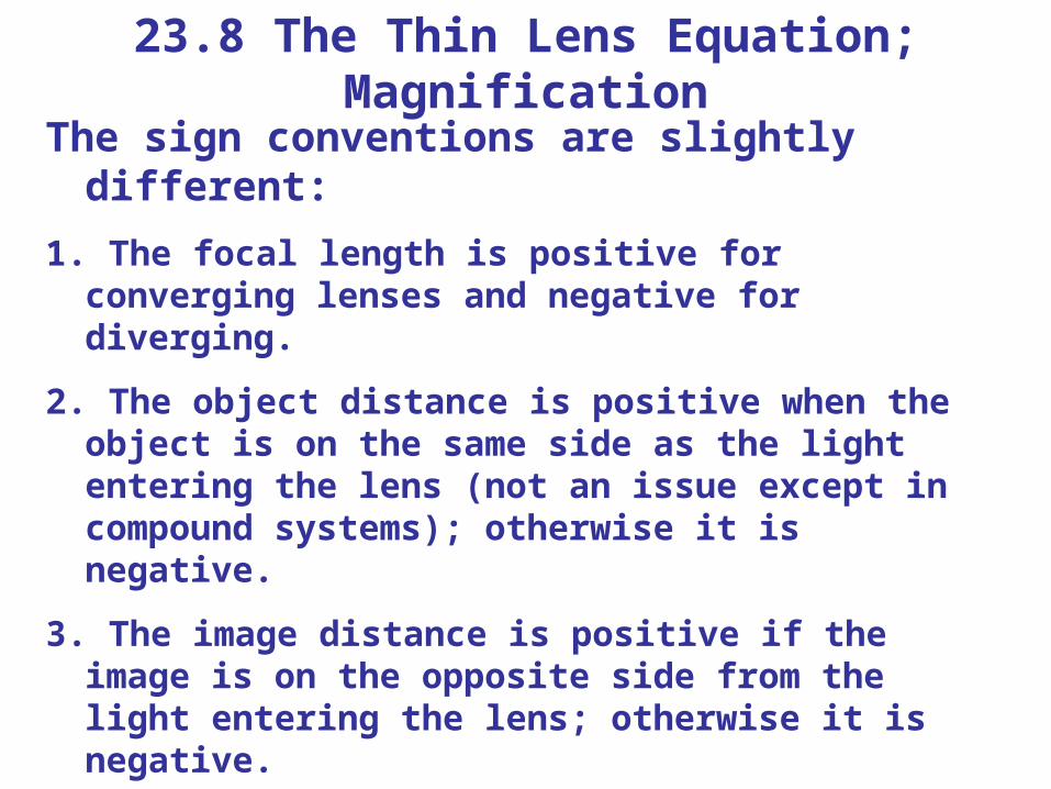
23.8 The Thin Lens Equation; Magnification
The sign conventions are slightly different:1. The focal length is positive for converging lenses
and negative for diverging.
2. The object distance is positive when the object is on the same side as the light entering the lens (not an issue except in compound systems); otherwise it is negative.
3. The image distance is positive if the image is on the opposite side from the light entering the lens; otherwise it is negative.
4. The height of the image is positive if the image is upright and negative otherwise.
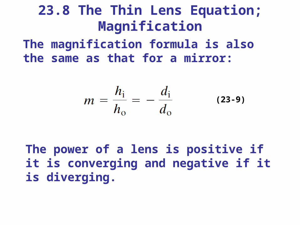
23.8 The Thin Lens Equation; Magnification
The magnification formula is also the same as that for a mirror:
(23-9)
The power of a lens is positive if it is converging and negative if it is diverging.
23.8 The Thin Lens Equation; Magnification
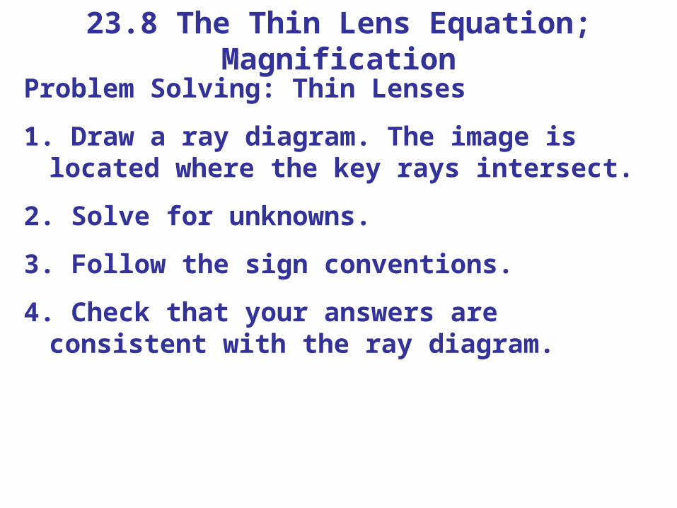
Problem Solving: Thin Lenses
1. Draw a ray diagram. The image is located where the key rays intersect.
2. Solve for unknowns.
3. Follow the sign conventions.
4. Check that your answers are consistent with the ray diagram.
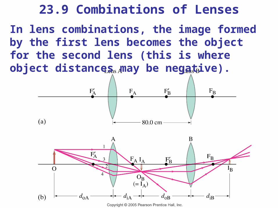
23.9 Combinations of LensesIn lens combinations, the image formed by the first lens becomes the object for the second lens (this is where object distances may be negative).
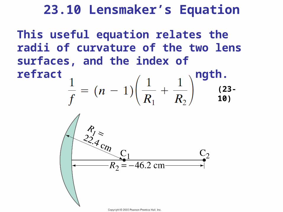
23.10 Lensmaker’s Equation
This useful equation relates the radii of curvature of the two lens surfaces, and the index of refraction, to the focal length.
(23-10)
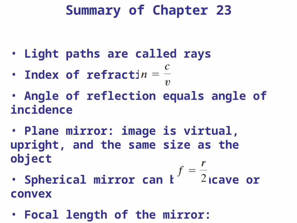
Summary of Chapter 23
• Light paths are called rays
• Index of refraction:
• Angle of reflection equals angle of incidence
• Plane mirror: image is virtual, upright, and the same size as the object
• Spherical mirror can be concave or convex
• Focal length of the mirror:
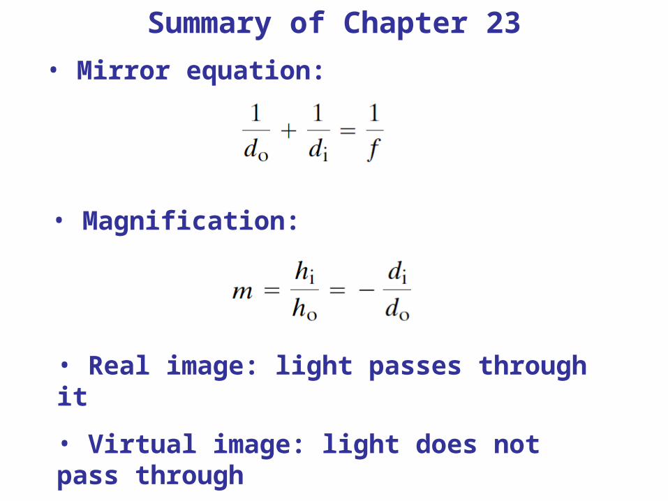
Summary of Chapter 23• Mirror equation:
• Magnification:
• Real image: light passes through it
• Virtual image: light does not pass through
Summary of Chapter 23
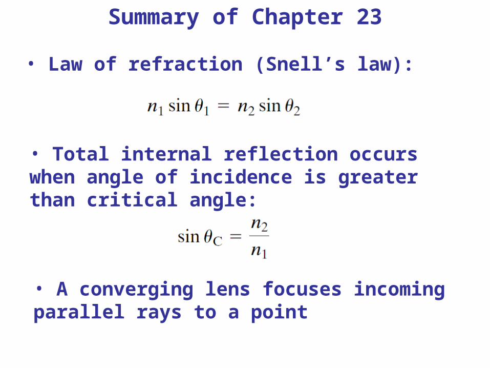
• Law of refraction (Snell’s law):
• Total internal reflection occurs when angle of incidence is greater than critical angle:
• A converging lens focuses incoming parallel rays to a point
Summary of Chapter 23
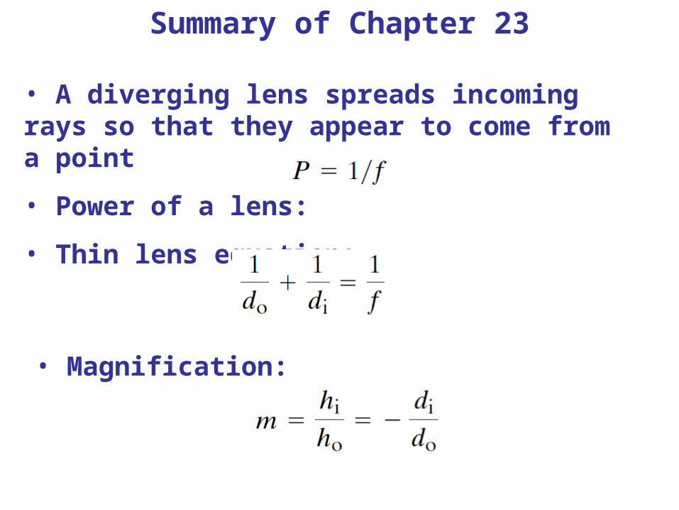
• A diverging lens spreads incoming rays so that they appear to come from a point
• Power of a lens:
• Thin lens equation:
• Magnification: