Slide 1 Towards Hard Real-time Performance in a Highly Asynchronous Multitasking MSP430 Application...
24
Slide www.pumpkininc.com Towards Hard Real-time Performance in a Highly Asynchronous Multitasking MSP430 Application Andrew E. Kalman, Ph.D.
Transcript of Slide 1 Towards Hard Real-time Performance in a Highly Asynchronous Multitasking MSP430 Application...
Slide 1
www.pumpkininc.com
Towards Hard Real-time Performance in a Highly Asynchronous Multitasking
MSP430 ApplicationAndrew E. Kalman, Ph.D.
Slide 2
www.pumpkininc.comOutline• Overview
• Part I: TimerA does PWM
• Part II: TimerB drives a Stepper
• Part III: Adding another Interrupt
• Part IV: Strategies
• Part V: Application Details
• Part VI: Summary

Slide 3
www.pumpkininc.comOverview• Wish to create an MSP430F149 (2 timers, 2 USARTs, no
DMA, etc.) application with the following characteristics: Simple 24kHz 10-100% PWM output with zero jitter. Complex programmable 10kHz stepper motor control waveform
with zero jitter. Serial port for command & status. Variety of additional functionality (debug, test, user-friendly status,
etc.)

Slide 4
www.pumpkininc.comTimerA does PWM• TimerA in compare mode:
Init: TACTL = TASSEL1+TACLR; // SMCLK, /8, Clear TAR TACCTL0 = 0; TACCTL1 = OUTMOD_2; // CCR1 reset/set P1OUT &= ~(BIT2); // Output is initially LOW P1DIR |= BIT2; // TA1 is output, tied P1SEL |= BIT2; // to CCR1 TACCR0 = PWM_STEPS; // PWM steps / resolution TACCR1 = 0; // Initially @ 0%. TACTL |= MC1 + MC0; // Enable counter in up/down mode.
Enable: TACCR1 = TACCR0; // Output is HIGH (dc)
OR TACCR1 = 0; // Output is LOW (dc)
OR TACCR1 = power; // Output is PWM
• TA1 (P1.2) is a simple, zero-jitter, hardware-only PWM.
Slide 5
www.pumpkininc.com
• 24kHz PWM via TA1 has no jitter, because: Output transitions occur automatically with proper peripheral
setup. No interrupt dependence – neither uses nor is affected by
interrupts.
• No steady-state dependency on runtime code means: Software does not affect TA1 operation. TA1 operation does not affect software.
• Used like this, TA1 is a “set and forget” peripheral.
• Only hardware is required to keep TA1 jitter-free. No software involved, no load on CPU. Completely synchronous.
• Guaranteed hard real-time.
Part I Review

Slide 6
www.pumpkininc.comTimerB drives a Stepper• Over time, stepper motor drive waveform consists of an
acceleration ramp, a constant-velocity section, and a deceleration ramp.
• Distance to move, accel / decel phase, and speed (i.e., frequency) all user-specifiable via command interface.
Slide 7
www.pumpkininc.comPart II (cont’d)• Waveform jitter will cause stepper motor to stall – bad!
• Maximum frequency of 10kHz via TimerB clock of 640kHz.
• Varying output frequencies and large number (>500k) of waveform points requires an algorithmic approach on the MSP430. Peripheral hardware is not enough … must also reconfigure TimerB0 on-the-fly at each output transition. Software must be part of the equation!
• Lack of DMA requires a fully-algorithmic approach. For MSP430s with DMA, certain optimizations are possible ...
• Use TimerB0 (P4.1) in compare mode.
• Output toggles based on TBR = TBCCR0 match.
Slide 8
www.pumpkininc.comPart II (cont’d)• TimerB is operated in continuous mode, so
TBCCR0 must be updated after every compare match. This is done via the TimerB0 interrupt.
• A TimerB0 interrupt means the output compare event has already occurred! Use each interrupt to configure TB0 for the next output compare. Init:
TBCCR0_reload = (TB_CLK/(TB_DIV*2)) / MOVE_START_FREQ; TBCCR0 += 100; TBCCTL0 = OUTMOD_4+CCIE; // !!
ISR: Reloads TBCCR0 based on when next output compare must occur. Reloads TBCCTL0 based on what output mode we need. Manages status variables (e.g. total count). Disables TimerB0 interrupts when done. State machine minimizes worst-case path in ISR to just a few lines of C.
Slide 9
www.pumpkininc.comPart II Review• TimerB0 ISR runs merrily along, because:
TimerB0 is the application’s highest active interrupt source. TimerB0 is never preempted.
TimerB0 interrupt is always enabled (while stepper is moving).
• 10kHz stepper motor control via TB0 has no jitter, because: Output compares are setup via software in TimerB0 ISR, but
occur based on TimerB match. TimerB0 ISR is fast enough to guarantee no missed output
compare events. E.g., if output compare just happened (i.e., TimerB0’s CCIFG was just set) and next output compare event is 5,000 cycles from now, TBCCR0 only needs to be updated (via the ISR) sometime within the next 5,000 cycles.
Slide 10
www.pumpkininc.comPart II Review (cont’d)• Hardware and software are required to keep stepper
operating and jitter-free.
• Hardware’s performance based on peripheral clocks (e.g., SMCLK).
• Software’s performance based on MCLK (CPU clock).
• TimerB0 has placed a load on the CPU, albeit a small one.
• TimerB0 interrupts occur completely asynchronously.
• Guaranteed hard real-time as long as CPU can keep up (easy so far).
• 10kHz stepper means TimerB0 interrupt must be serviced within 100us!
Slide 11
www.pumpkininc.com
• Application now has: TimerA1, no interrupts, simple reset/set compare mode, constant
CCR, therefore simply periodic, no CPU load, no jitter. TimerB0, interrupts active when stepper waveform being
generated, output mode and CCR changes unpredictable, jitter avoided due to highest priority, fast ISR and output compare hardware, small CPU load.
• Adding these to the application have no effect on TA1 or TB0’s jitter-free performance: More mainline / background / task code. More “set and forget” peripherals (i.e., no interrupts used).
• Interrupts are inherently asynchronous.
• What happens when we add another interrupt, with the software to support it?
Adding another Interrupt

Slide 12
www.pumpkininc.comPart III (cont’d)• Other interrupts have lower priority than TimerB0. Should
we be worried? Yes, because: If another interrupt is being serviced when a TimerB0 interrupt
occurs, it holds off the TimerB0 ISR: ISR jitter. Now another foreground process (another ISR handler) is
competing for CPU cycles, potentially at the worst possible time.
• Interrupt responsiveness can be non-critical (e.g., Tx ISR, char is late) or critical (e.g., Rx ISR, char is lost).
• Once another interrupt source is added to the mix, we are now concerned with the responsiveness of our (critical) ISR(s).
• Degraded interrupt response times ultimately lead to hard real-time failures. Due to hardware (interrupt handling) and software (feeding the peripheral via its ISR).

Slide 13
www.pumpkininc.comPart III (cont’d)• Properties of MSP430 interrupt handling:
Native interrupt latency of 6 cycles for every interrupt source. No interrupt will be serviced until all of the pending higher-priority
interrupts have been serviced. For nested interrupts (uncommon, but possible in the MSP430 via
explicit GIE control within an ISR): The highest-priority interrupt can be held off for an additional 6 cycles
+ 1 instruction to set GIE. Every interrupt can be held off for the sum of the lengths of all of the
higher-priority ISRs. For non-nested interrupts (typical for MSP430 applications):
The highest-priority interrupt can be held off for the length of the longest ISR, regardless of that interrupt’s priority.
Every interrupt can be held off for the sum of the lengths of all of the higher-priority ISRs.
Slide 14
www.pumpkininc.comPart III (cont’d)• Manipulating an interrupt’s enable bit compromises its
response time.
• Interrupts are temporarily suppressed: To protect shared global variables against corruption. To protect against unwanted reentrancy.
• Software to temporarily suppress interrupts comes from: Mainline / background / task code – monitor functions. RTOS critical sections.
• Solution: move any ISR processing that can be “moved upstairs” out of the ISR and into mainline / background / task code. While less efficient from a CPU utilization standpoint, this improves interrupt responsiveness. Utilize atomic operations (e.g., BIS.W, BIT.W, BIC.W instructions) for ISR-to-mainline / background / task communications.
Slide 15
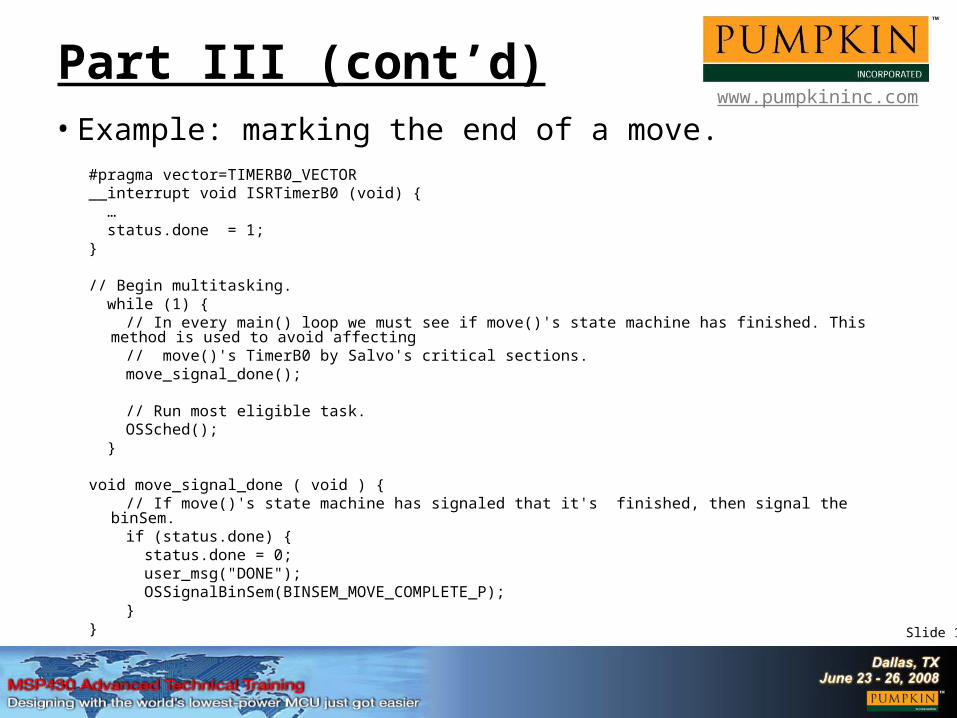
www.pumpkininc.comPart III (cont’d)• Example: marking the end of a move.
#pragma vector=TIMERB0_VECTOR__interrupt void ISRTimerB0 (void) { … status.done = 1;}
// Begin multitasking. while (1) { // In every main() loop we must see if move()'s state machine has finished. This method is used to avoid affecting // move()'s TimerB0 by Salvo's critical sections. move_signal_done();
// Run most eligible task. OSSched(); }
void move_signal_done ( void ) { // If move()'s state machine has signaled that it's finished, then signal the binSem. if (status.done) { status.done = 0; user_msg("DONE"); OSSignalBinSem(BINSEM_MOVE_COMPLETE_P); }}

Slide 16
www.pumpkininc.comPart III Review• Priorities dictate the hard real-time capabilities of your
application: Hardware (i.e., interrupt) priorities limit the performance of
peripherals. Software (e.g., RTOS) priorities limit the performance of the
supporting software.
• Time spent in ISRs critically impacts the system’s responsiveness to interrupts.
• By characterizing the time your application spends in ISRs, you can find the system’s worst possible interrupt response time. This in turn places a limit on how fast the hard real-time aspects of your application can be.
• Limiting factor is instruction clock speed (MCLK).

Slide 17
www.pumpkininc.comStrategies• The fundamental issue is to create software that is
“primed” to respond as quickly as possible to asynchronous events. Whenever possible, avoid polling.
• Select interrupts based on their priorities.
• Write fast ISRs.
• Keep critical interrupts enabled when active.
• Offload non-time-critical processing to mainline / background / task code.
• Prioritize mainline / background / task code. An event-driven, priority-based RTOS provides the framework for this.
• For asynchronous processes, it’s all about priorities!

Slide 18
www.pumpkininc.comApplication Details
• MCLK @ 5.12MHz
• Peripherals in use: TimerB0: stepper, interrupts enabled while stepping. TimerB1: 100Hz periodic interrupt, calls RTOS system tick service. TimerB3: s/w Tx UART @ 9600,N,8,1, interrupt-driven, calls state
machine to bit-bang next bit. TimerA1: PWM, no interrupts. USART1: Tx @ 9600,N,8,1, interrupt-driven, library call moves next
outgoing char from buffer into TXBUF. USART1: Rx @ 9600,N,8,1, interrupt-driven, library call moves
newest incoming char from RXBUF into buffer, signals waiting command processor task via RTOS semaphore.
• No interrupt nesting.
• Salvo RTOS: 11 tasks, 6 events.

Slide 19
www.pumpkininc.comPart V (cont’d)
• Idling hook invokes LPM0. I/O bit high when not in LPM0 gives quick indication of CPU load.
• Salvo critical sections suppress only TimerB1 and Rx1 interrupts – no global interrupt suppression via GIE. Multitasking therefore has no impact on stepper, PWM or Tx1 interrupts.
• Since all mainline / background / task code has lesser priority than the interrupt-based processes (e.g. stepper), its performance degrades gracefully under heavy CPU load.
• Asynchronous processes at the mainline / background / task level can be added ad infinitum, but without hardware / interrupt support, they cannot be guaranteed to be hard real-time.

Slide 20
www.pumpkininc.comSummary
• ISR-independent peripheral operation has deterministic timing, regardless of the state of the rest of the system.
• Interrupt processing is inherently asynchronous.
• The performance of an asynchronous system is measured by its responsiveness to events.
• Getting the desired functionality out of a particular peripheral often requires using the peripheral’s interrupt(s), and hence, writing runtime software for it. Effect on timing due to software is not easily quantifiable in an asynchronous system.

Slide 21
www.pumpkininc.comPart VI (cont’d)
• ISRs are the highest-priority on-chip processes, and preempt mainline / background / task code.
• All ISRs benefit from all ISRs being fast.
• For maximum ISR performance, a given interrupt must always be enabled.
• The presence of lower-priority interrupts compromises the responsiveness of higher-priority interrupts. Dependent on number and speed of ISRs, not just priorities.
• By decoupling interrupt responsiveness from associated peripheral’s operation, peripheral jitter can be eliminated.
• Hard real-time operation requires a guaranteed maximum interrupt response time, application-wide.

Slide 22
www.pumpkininc.com
Live Demo
Q&A Session
Thank you for attending this
Pumpkin seminar at the ATC 2008!

Slide 23
www.pumpkininc.comNotice
This presentation is available online in Microsoft® PowerPoint® and Adobe® Acrobat® formats at:
www.pumpkininc.com/content/doc/press/Pumpkin_MSP430ATC2008.ppt
and:
www.pumpkininc.com/content/doc/press/Pumpkin_MSP430ATC208.pdf

Slide 24
www.pumpkininc.comAppendix• Speaker information
Dr. Kalman is Pumpkin's president and chief technology architect. He entered the embedded programming world in the mid-1980's. After co-founding Euphonix, Inc – the pioneering Silicon Valley high-tech pro-audio company – he founded Pumpkin, Inc. to explore the feasibility of applying high-level programming paradigms to severely memory-constrained embedded architectures. He is the creator of the Salvo RTOS and the CubeSat Kit. He holds two United States patents and is a consulting professor in the Department of Aeronautics & Astronautics at Stanford University. Contact Dr. Kalman at [email protected].
• Acknowledgements Pumpkin’s Salvo and CubeSat Kit customers, whose real-world experience with our products helps us improve
and innovate.
• Salvo information More information on Pumpkin’s Salvo RTOS can be found at http://www.pumpkininc.com/. The Pumpkin libraries used to drive the MSP430’s UART in this example are available at
http://www.pumpkininc.com/library/msp430/.
• Copyright notice© 2000-2008 Pumpkin, Inc. All rights reserved. Pumpkin and the Pumpkin logo, Salvo and the Salvo logo, The RTOS that runs in tiny places, CubeSat Kit, CubeSat Kit Bus and the CubeSat Kit logo are all trademarks of Pumpkin, Inc. Don’t leave Earth without it is a service mark of Pumpkin, Inc. All other trademarks and logos are the property of their respective owners. No endorsements of or by third parties listed are implied. All specifications subject to change without notice.
First presented as the final Designing with MSP430 session of the TI MSP430 Advanced Technical Conference in Dallas, Texas at 1pm on Thursday, June 26, 2008.