Slide 1 Unified Process Introduction and History.
99
Slide 1 Unified Process Introduction and History
-
Upload
poppy-morgan -
Category
Documents
-
view
219 -
download
0
Transcript of Slide 1 Unified Process Introduction and History.

Slide 1
Unified Process Introduction and History

Slide 2
Topics
Unified Process Unified Process Workflows UML (in general) Use Cases

Slide 3
New or changed
requirements
New or changed
system
Software EngineeringProcess
What Is a Process?
Defines Who is doing What, When to do it, and How to reach a certain goal.

Slide 4
What is the Unified Process
A popular iterative modern process model (framework) derived from the work on the UML and associated process.
The leading object-oriented methodology for the development of large-scale software
Maps out when and how to use the various UML techniques

Slide 5
What is the Unified Process
Develop high-risk elements in early iterations
Deliver value to customerAccommodate change early on in projectWork as one teamAdaptable methodology - can be modified for the
specific software product to be developed
2-dimensional systems development process described by a set of phases and workflows
Utilizes Millers Law

Slide 6
Miller’s Law
At any one time, we can concentrate on only approximately seven chunks (units of information)
To handle larger amounts of information, use stepwise refinement• Concentrate on the aspects that are currently
the most important• Postpone aspects that are currently less critical

Slide 7
History of UP
Some roots in the “Spiral Model ” of Barry Boehm
Core initial development around 1995-1998 Large Canadian Air Traffic Control project as
test bed Philippe Kruchten chief architect of UP/RUP Rational Corporation had commercial
product in mind (RUP, now owned by IBM) but also reached out to public domain (UP)

Slide 8
Creating the Unified Process
Rational Unified Process 5.01998
Rational Objectory Process 4.11996-1997
Objectory Process 1.0-3.81987-1995
Ericsson Approach
Rational Approach
IBM Approach
Unified Process 1998
OO Approach

Slide 9
Rational Unified Process (RUP)
Commercial version of Unified Process from IBM• A specific commercial subclass that both
extends and overrides the features of the Unified Process
Supplies all of the standards, tools, and other necessities that are not included in the Unified Process

Slide 10
The Rational Unified Process
RUP is a method of managing OO Software Development It can be viewed as a Software Development Framework
which is extensible and features:
• Iterative Development• Requirements Management• Component-Based Architectural Vision• Visual Modeling of Systems• Quality Management• Change Control Management

Slide 11
RUP Features
Online Repository of Process Information and Description in HTML format
Templates for all major artifacts, including:• RequisitePro templates (requirements tracking)
• Word Templates for Use Cases
• Project Templates for Project Management Process Manuals describing key processes

Slide 12
The Unified Process
In Perspective:• Most of the world is NOT object oriented and doesn’t use
the process we’re presenting here.
• However, in practice, they do something very similar that works for them.
In 1999, Booch, Jacobson, and Rumbaugh published a complete object-oriented analysis and design methodology that unified their three separate methodologies. Called the Unified Process.
The Unified Process is an adaptable methodology
• It has to be modified for the specific software product to be developed
Slide 13
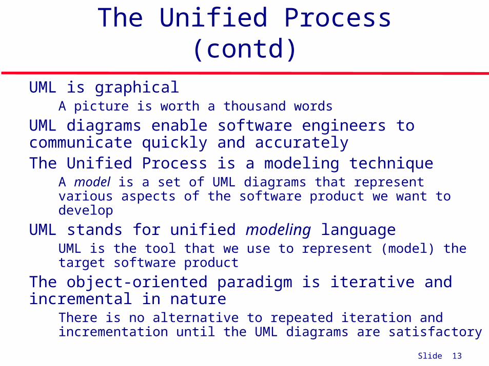
The Unified Process (contd) UML is graphical
• A picture is worth a thousand words UML diagrams enable software engineers to communicate
quickly and accurately The Unified Process is a modeling technique
• A model is a set of UML diagrams that represent various aspects of the software product we want to develop
UML stands for unified modeling language• UML is the tool that we use to represent (model) the target software
product The object-oriented paradigm is iterative and incremental in
nature• There is no alternative to repeated iteration and incrementation until
the UML diagrams are satisfactory

Slide 14
Iteration and Incrementation
We cannot learn the complete Unified Process in one semester or quarter • Extensive study and unending practice are needed• The Unified Process has too many features• A case study of a large-scale software product is huge
In this book, we therefore cover much, but not all, of the Unified Process• The topics covered are adequate for smaller products
To work on larger software products, experience is needed • This must be followed by training in the more complex aspects of
the Unified Process

Slide 15
Unified Process Phases

Slide 16
Basic Characteristics of the Unified Process
• Object-oriented• Use-case driven• Architecture centric• Iteration and incrementation

Slide 17
Basic Characteristics of the Unified Process
• Object-oriented• Utilizes object oriented technologies.
Classes are extracted during object-oriented analysis and designed during object-oriented design.

Slide 18
Basic Characteristics of the Unified Process
Use-case driven• Utilizes use case model to describe
complete functionality of the system
Req.ts Impl. Test
Use Cases bind these workflows together
Analysis Design

Slide 19
Basic Characteristics of the Unified Process
• Architecture centric• Embodies the most significant aspects of
the system• View of the whole design with the
important characteristics made more visible
• Expressed with class diagram
Slide 20
Basic Characteristics of the Unified Process
Iteration and incrementation• Way to divide the work• Iterations are steps in the process, and
increments are growth of the product• The basic software development process
is iterative • Each successive version is intended to be closer to
its target than its predecessor

Slide 21
The Rational Unified Process
RUP is a method of managing OO Software Development It can be viewed as a Software Development Framework
which is extensible and features:
• Iterative Development
• Requirements Management
• Component-Based Architectural Vision
• Visual Modeling of Systems
• Quality Management
• Change Control Management
Slide 22
An Iterative Development Process...
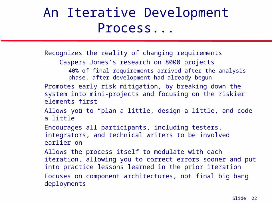
Recognizes the reality of changing requirements• Caspers Jones’s research on 8000 projects
• 40% of final requirements arrived after the analysis phase, after development had already begun
Promotes early risk mitigation, by breaking down the system into mini-projects and focusing on the riskier elements first
Allows you to “plan a little, design a little, and code a little” Encourages all participants, including testers, integrators, and
technical writers to be involved earlier on Allows the process itself to modulate with each iteration, allowing
you to correct errors sooner and put into practice lessons learned in the prior iteration
Focuses on component architectures, not final big bang deployments

Slide 23
The Unified Process is Engineered
Describe a Use Case
Use case package
Use case
responsible for
Analyst
Artifact
A piece of information that is produced, modified, or used by a process
Worker
A role played by an individual or a team
Activity
A unit of work

Slide 24
The Unified Process is a Process Framework
There is NO Universal Process!
• The Unified Process is designed for flexibility and extensibility
» allows a variety of lifecycle strategies
» selects what artifacts to produce
» defines activities and workers
» models concepts

Slide 25
Unified Process Model
Phase iteration
Inception Elaboration Construction Transition

Slide 26
Goals and Features of Each Iteration
The primary goal of each iteration is to slowly chip away at the risk facing the project, namely:
• performance risks
• integration risks (different vendors, tools, etc.)
• conceptual risks (ferret out analysis and design flaws)
Perform a “miniwaterfall” project that ends with a delivery of something tangible in code, available for scrutiny by the interested parties, which produces validation or correctives
Each iteration is risk-driven The result of a single iteration is an increment--an
incremental improvement of the system, yielding an evolutionary approach
Slide 27
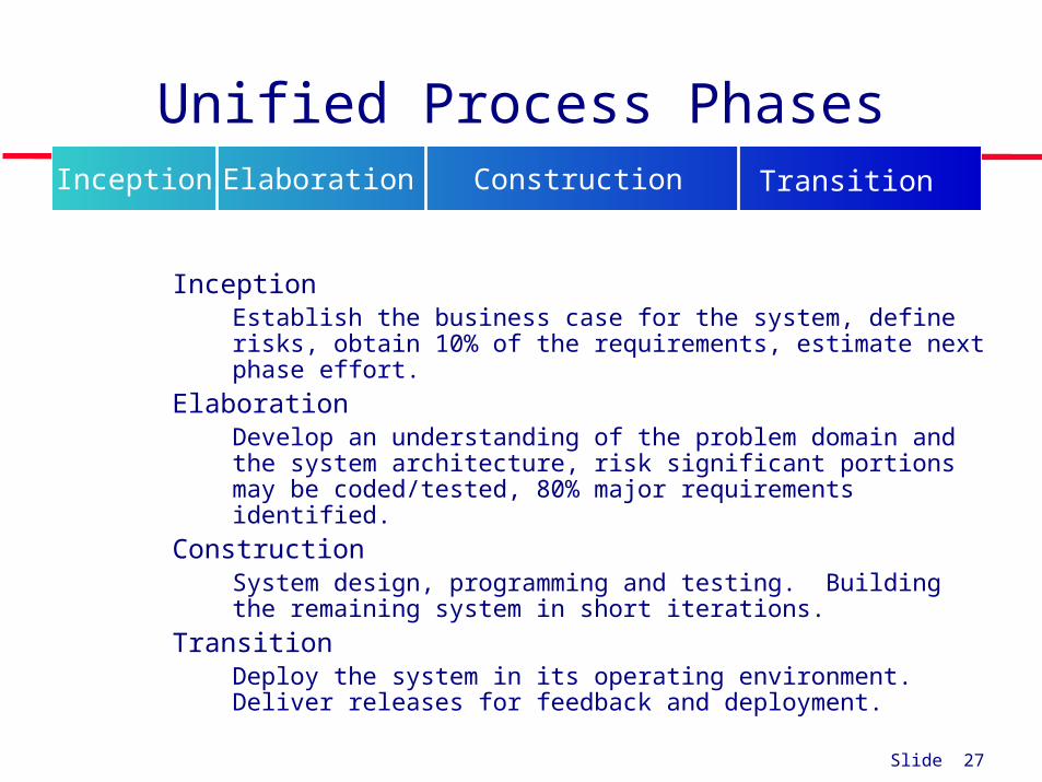
Unified Process Phases
Inception• Establish the business case for the system, define risks, obtain
10% of the requirements, estimate next phase effort. Elaboration
• Develop an understanding of the problem domain and the system architecture, risk significant portions may be coded/tested, 80% major requirements identified.
Construction• System design, programming and testing. Building the
remaining system in short iterations. Transition
• Deploy the system in its operating environment. Deliver releases for feedback and deployment.
Inception Elaboration Construction Transition

Slide 28
The Phases/Workflows of the Unified Process
Figure 3.1
Phase is Business context of a step
Workflow is Technical context
of a step

Slide 29
The Phases/Workflows of the Unified Process
Figure 3.1
NOTE: Most of the requirements work or workflow is done in the inception phase.
However some is done later.
Slide 30
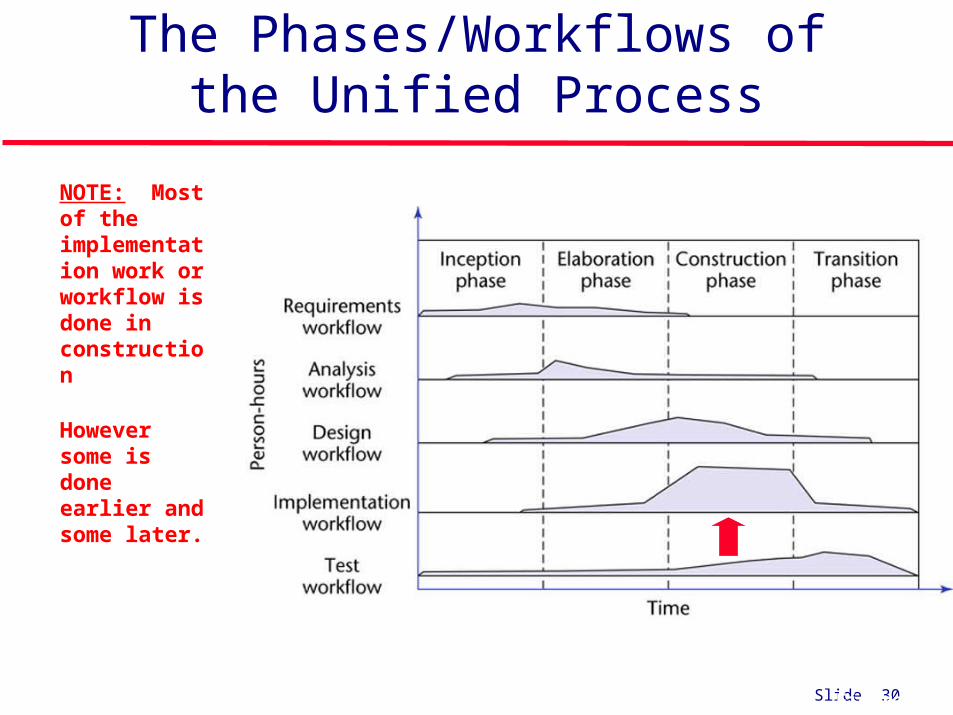
The Phases/Workflows of the Unified Process
Figure 3.1
NOTE: Most of the implementation work or workflow is done in construction
However some is done earlier and some later.
Slide 31
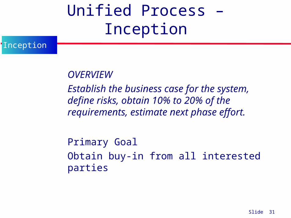
Unified Process – Inception
• OVERVIEW• Establish the business case for the system,
define risks, obtain 10% to 20% of the requirements, estimate next phase effort.
• Primary Goal• Obtain buy-in from all interested parties
Inception

Slide 32
Unified Process – Inception Objectives
Gain an understanding of the domain. Delimit the scope of the proposed project with a
focus on the subset of the business model that is covered by the proposed software product
Define an initial business case for the proposed system including costs, schedules, risks, priorities, and the development plan.
Define an any needed prototypes to mitigate risks. Obtain stakeholder concurrence on scope
definition, expenditures, cost/schedule estimates, risks, development plan and priorities.
Inception

Slide 33
Unified Process – Inception Activities
Project Initiation activities that allow new ideas to be evaluated for potential software development
Project Planning work activities to build the team and perform the initial project planning activities
Requirements work activities to define the business case for this potential software.
Analysis and maybe Design work activities to define and refine costs, risks, scope, candidate architecture.
Testing activities to define evaluation criteria for end-product vision
Inception

Slide 34
Unified Process – Inception Activities
Project Initiation Start with an idea Specify the end-product vision Analyze the project to assess scope Work the business case for the
project including overall costs and schedule, and known risks
Identify Stakeholders Obtain funding
Inception

Slide 35
Unified Process – Inception Activities
• Project Planning• Build Team• Define initial iteration• Assess project risks and risk mitigation plan
Inception
There is insufficient information at the beginning of the inception phase to plan the entire development
The only planning that is done at the start of the project is the planning for the inception phase itself
For the same reason, the only planning that can be done at the end of the inception phase is the plan for just the next phase, the elaboration phase
Slide 36
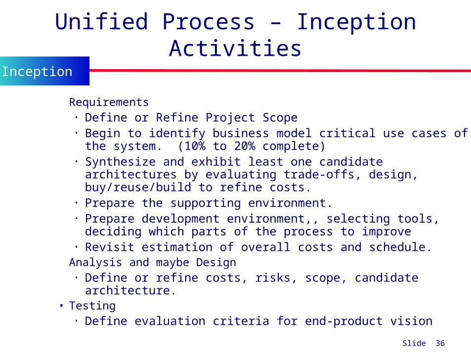
Unified Process – Inception Activities
• Requirements • Define or Refine Project Scope• Begin to identify business model critical use cases of the system.
(10% to 20% complete)• Synthesize and exhibit least one candidate architectures by
evaluating trade-offs, design, buy/reuse/build to refine costs. • Prepare the supporting environment. • Prepare development environment,, selecting tools, deciding
which parts of the process to improve• Revisit estimation of overall costs and schedule.
• Analysis and maybe Design • Define or refine costs, risks, scope, candidate architecture.
• Testing• Define evaluation criteria for end-product vision
Inception

Slide 37
Unified Process – Inception Activities
Risk Assessment Activities What are the risks involved in developing the software
product, and How can these risks be mitigated?
• Does the team who will develop the proposed software product have the necessary experience?
• Is new hardware needed for this software product?• If so, is there a risk that it will not be delivered in time?
• If so, is there a way to mitigate that risk, perhaps by ordering back-up hardware from another supplier?
• Are software tools needed? • Are they currently available?
• Do they have all the necessary functionality?
Inception

Slide 38
Unified Process – Inception Activities
Risk Assessment Activities There are three major risk categories:
• Technical risks • See earlier slide
• The risk of not getting the requirements right• Mitigated by performing the requirements workflow
correctly
• The risk of not getting the architecture right• The architecture may not be sufficiently robust
To mitigate all three classes of risks• The risks need to be ranked so that the critical
risks are mitigated first
Inception
Slide 39
Unified Process – Inception Deliverables
Primary deliverables: A vision document Initial version of the environment adoption
(candidate) Any needed models or artifacts such as a domain
model, business model, or requirements and analysis artifacts.
Project plan, with phases and iterations with a more detailed plan for the elaboration phase.
A project glossary One or several prototypes.
Inception

Slide 40
Unified Process – Inception Deliverables
Primary deliverables:• A vision document NOTE: we use IEEE SRS Sec I,II
• A general vision of the project’s core requirements, key features and main constraints. Sets the scope of the project, identifies the primary requirements and constraints, sets up an initial project plan, and describes the feasibility of and risks associated with the project
• Any needed models or artifacts such as a domain model, business model, or requirements and analysis artifacts.• An use-case model (10%-20% complete) – all Use Cases and Actors
that can be identified so far with initial ordering.• An initial business case, which includes business context, success
criteria (revenue projection, market recognition, and so on), and financial forecast;
• A risk assessment analysis;
Inception
Slide 41
Unified Process – Inception Questions
Is the proposed software product cost effective? How long will it take to obtain a return on investment? Alternatively, what will be the cost if the company decides
not to develop the proposed software product? If the software product is to be sold in the marketplace,
have the necessary marketing studies been performed? Can the proposed software product be delivered in time? If the software product is to be developed to support the
client organization’s own activities, what will be the impact if the proposed software product is delivered late?
Inception

Slide 42
Unified Process – Elaboration Phase
Elaboration• Develop an understanding of the problem domain
and the system architecture, risk significant portions may be coded/tested, 80% major requirements identified.
• The goal of the elaboration phase is to baseline the most significant requirements.
Elaboration
Slide 43
Unified Process – Elaboration Objectives
Elaboration Objectives To refine the initial requirements and business case To ensure architecture, requirements, and plans are
stable To monitor and address all architecturally significant
risks of the project To refine or establish a baselined architecture To produce an evolutionary, throwaway, or
exploratory prototypes To demonstrate that the baselined architecture will
support the requirements of the system at a reasonable cost and in a reasonable time.
To establish a supporting environment. To produce the project management plan
Elaboration

Slide 44
Unified Process – Elaboration Activities
Elaboration Essential Workflow Progress
All but completing the requirements workflow
Performing virtually the entire analysis workflow
Starting the design workflow by performing the architecture design
Performing any construction workflows needed for prototypes to eliminate risks
Elaboration

Slide 45
Unified Process – Elaboration Activities
Elaboration Essential Activities
Analyze the problem domain. Define, validate and baseline the architecture Refine the Vision to understand the most critical Use Cases Create and baseline iteration plans for construction phase. Refine the development business case Put in place the development environment, Refine component architecture and decide build/buy/reuse Develop a project plan and schedule. Mitigate high-risk elements identified in the previous phase.
Elaboration

Slide 46
Unified Process – Elaboration Deliverables
Primary deliverables: Requirements model for the system The completed domain model (use cases, classes)
The completed business model (costs, benefits,risks)
The completed requirements artifacts The completed analysis artifacts Updated Architectural model Software project management plan
Elaboration

Slide 47
Unified Process – Elaboration Outcomes
Use Case model (at least 80% complete).• All Use Cases identified.• All Actors identified.• Most Use-Case descriptions developed.
Supplementary requirements.• (non-functional or not associated with a Use Case)
Software architecture description. Executable architectural prototype. Revised risk list and revised business case. Development plan for overall project.
• coarse grained project plan, with iterations and evaluation criteria for each iteration.
Updated development case that specifies process to be used. Preliminary user manual (optional).
Elaboration
Slide 48
Unified Process – Elaboration Questions
Is the vision of the product stable? Is the architecture stable? Does the executable demonstration show that the major risk
elements have been addressed and credibly resolved? Is the plan for the construction phase sufficiently detailed and
accurate? Do all stakeholders agree that the current vision can be
achieved if the current plan is executed to develop the complete system, in the context of the current architecture?
Is the actual resource expenditure versus planned expenditure acceptable?
Elaboration

Slide 49
Unified Process – Construction Phase
Construction• System design, programming and
testing. Building the remaining system in short iterations.
• The goal of the construction phase is to clarify the remaining requirements and complete the development of the first operational quality version of the software product.
Construction

Slide 50
Unified Process – Construction Objectives
Construction Objectives Minimizing development costs. Achieving adequate quality as rapidly as
practical Achieving useful versions as rapidly as practical Complete analysis, design, development and
testing of functionality. To iteratively and incrementally develop a
complete product To decide if the software, sites, and users are
deployment ready. To achieve parallelism in the work of
development teams.
Construction

Slide 51
Unified Process – Construction Activities
Construction Essential Activities
Complete component development and testing (beta release)
Assess product releases against acceptance criteria for the vision. (Unit, Integration, Functional and System testing)
Integrate all remaining components and features into the product
Assure resource management control and process optimization
Construction

Slide 52
Unified Process – Construction Deliverables
Primary deliverables• Working software system (beta release
version) • Associated documentation• Acceptance testing documentation• Updated project management
deliverables (plan, risks, business case)• User Manuals
Construction

Slide 53
Unified Process – Construction Outcomes
A product ready to put into the hands of end users.
The software product integrated on the adequate platforms.
The user manuals. A description of the current release.
Construction

Slide 54
Unified Process – Construction Questions
Is this product (beta test version) release stable and mature enough to be deployed in the user community?
Are all stakeholders ready for the transition into the user community?
Are the actual resource expenditures versus planned expenditures still acceptable?
Transition may have to be postponed by one release if the project fails to reach this milestone.
Construction

Slide 55
Unified Process – Transition Phase
Transition• Deploy the system in its operating environment.
Deliver releases for feedback and deployment.
• The focus of the Transition Phase is to ensure that software is available for its end users and meets their needs. The Transition Phase can span several iterations, and includes testing the product in preparation for release, and making minor adjustments based on user feedback.
Transition

Slide 56
Unified Process – Transition Objectives
Transition Objectives
• Assess deployment baselines against acceptance criteria
• Achieve user self-supportability
• Achieving stakeholder concurrence of acceptance
Transition

Slide 57
Unified Process – Transition Activities
Transition Essential Activities Finalize end-user support material Test the deliverable product at the development site Validate beta test to assure user expectations met Fine-tune the product based on feedback Perform parallel operation of replaced legacy system Convert operational databases Train of users and maintainers Roll-out to the marketing, distribution and sales forces
Perform deployment engineering (cutover, roll-out performance tuning)
Transition
Slide 58
Unified Process – Transition Deliverables
Primary deliverable• Final product onto a production platform
Other deliverables• All the artifacts (final versions)• Completed manual
Transition

Slide 59
Phase Deliverables
Inception Phase Elaboration Phase
Construction Phase
Transition Phase
• The initial version of the domain model
• The initial version of the business model
• The initial version of the requirements artifacts
• A preliminary version of the analysis artifacts
• A preliminary version of the architecture
• The initial list of risks
• The initial ordering of the use cases
• The plan for the elaboration phase
• The initial version of the business case
• The completed domain model
• The completed business model
• The completed requirements artifacts
• The completed analysis artifacts
• An updated version of the architecture
• An updated list of risks
• The project management plan (for the rest of the project)
• The completed business case
• The initial user manual and other manuals, as appropriate
• All the artifacts (beta release versions)
• The completed architecture
• The updated risk list
• The project management plan (for the remainder of the project)
• If necessary, the updated business case
• All the artifacts (final versions)
• The completed manuals

Slide 60
UP Life cycle in four phases
Inception Elaboration Construction Transition
The Enterprise Unified Process (EUP) adds two more phases to this:
• Production: keep system useful/productive after deployment to customer
• Retirement: archive, remove, or reuse etc.

Slide 61
Example roles in UP
Stake Holder: customer, product manager, etc. Software Architect: established and maintains
architectural vision Process Engineer: leads definition and
refinement of Development Case Graphic Artist: assists in user interface design,
etc.

Slide 62
Some UP guidelines
Attack risks early on and continuously so, before they will attack you
Stay focused on developing executable software in early iterations
Prefer component-oriented architectures and reuse existing components
Quality is a way of life, not an afterthought

Slide 63
Six best “must” UP practices
1. Time-boxed iterations: avoid speculative powerpoint architectures”
2. Strive for cohesive architecture and reuse existing components:
- e.g. core architecture developed by small, co-located team
- then early team members divide into sub-project leaders

Slide 64
Six best “must” UP practices
3. Continuously verify quality: test early & often, and realistically by integrating all software at each iteration
4. Visual modeling: prior to programming, do at least some visual modeling to explore creative design ideas

Slide 65
Six best “must” UP practices
5. Manage requirements: find, organize, and track requirements through skillful means
6. Manage change: - disciplined configuration management
protocol, version control, - change request protocol- baselined releases at iteration ends

Slide 66
Unified Process Workflows

Slide 67
The Unified Process is a Process Framework
While the Unified Process is widely used, there is NO Universal Process!
• The Unified Process is designed for flexibility and extensibility
» allows a variety of lifecycle strategies
» selects what artifacts to produce
» defines activities and workers
» models concepts
» IT IS A PROCESS FRAMEWORK for development

Slide 68
The Unified Process
The Unified Process IS A 2-dimensional systems development
process described by a • set of phases and (dimension one)
• Workflows (dimension two)

Slide 69
The Unified Process
Phases• Describe the business steps needed to
develop, buy, and pay for software development.
• The business increments are identified as phases
Workflows• Describe the tasks or activities that a
developer performs to evolve an information system over time

Slide 70
Why a Two-Dimensional Model?
In an ideal world, each workflow would be completed before the next workflow is started
In reality, the development task is too big for this
As a consequence of Miller’s Law• The development task has to be divided into increments (phases)
Within each increment, iteration is performed until the task is complete
At the beginning of the process, there is not enough information about the software product to carry out the requirements workflow • Similarly for the other core workflows

Slide 71
Why a Two-Dimensional Model?
A software product has to be broken into subsystems. Even subsystems can be too large at times. Modules may be all that can be handled until a fuller understanding of all the parts of the product as a whole has been obtained
The Unified Process handles the inevitable changes well• The moving target problem• The inevitable mistakes
The Unified Process works for treating a large problem as a set of smaller, largely independent sub problems• It provides a framework for incrementation and iteration• In the future, it will inevitably be superseded by some better
methodology

Slide 72
Process Overview
Phases (time)
Workflow (tasks)
Inception Elaboration Construction Transition
Requirements
Analysis
Design
Implementation
Test

Slide 73
Static workflows
Workflow Description
Business modelling The business processes are modelled using business use cases.
Requirements Actors who interact with the system are identified and use cases aredeveloped to model the system requirements.
Analysis and design A design model is created and documented using architecturalmodels, component models, object models and sequence models.
Implementation The components in the system are implemented and structured intoimplementation sub-systems. Automatic code generation from designmodels helps accelerate this process.
Test Testing is an iterative process that is carried out in conjunction withimplementation. System testing follows the completion of theimplementation.
Deployment A product release is created, distributed to users and installed in theirworkplace.
Configuration andchange management
This supporting workflow managed changes to the system (seeChapter 29).
Project management This supporting workflow manages the system development (seeChapter 5).
Environment This workflow is concerned with making appropriate software toolsavailable to the software development team.

Slide 74
Primary Workflows
The Unified Process
PRIMARY WORKFLOWS• Requirements workflow• Analysis workflow• Design workflow• Implementation workflow• Test workflow• Post delivery maintenance workflow
Supplemental Workflows• Planning Workflow

Slide 75
Planning Workflow
Define scope of Project Define scope of next iteration Identify Stakeholders Capture Stakeholders expectation Build team Assess Risks Plan work for the iteration Plan work for Project Develop Criteria for iteration/project closure/success UML concepts used: initial Business Model, using class
diagram

Slide 76
Requirements Workflow
Primary focus• To determine the client’s needs by
eliciting both functional and nonfunctional requirements
Gain an understanding of the application domain
Described in the language of the customer
Workflow (tasks)
Requirements
Analysis
Design
Implementation
Testing

Slide 77
Requirements Workflow
The aim is to determine the client’s needs First, gain an understanding of the domain
• How does the specific business environment work Second, build a business model
• Use UML to describe the client’s business processes• If at any time the client does not feel that the cost is justified,
development terminates immediately It is vital to determine the client’s constraints
• Deadline -- Nowadays software products are often mission critical• Parallel running • Portability• Reliability• Rapid response time• Cost
The aim of this concept exploration is to determine• What the client needs, and• Not what the client wants
Workflow (tasks)
Requirements
Analysis
Design
Implementation
Testing
Slide 78
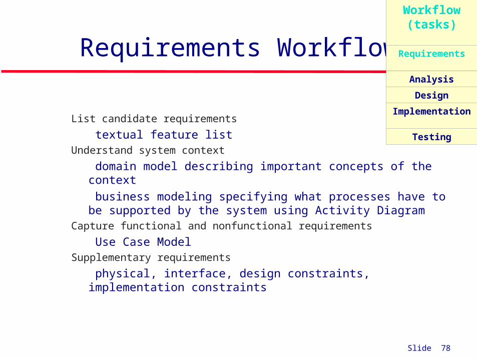
Requirements Workflow
List candidate requirements
• textual feature list Understand system context
• domain model describing important concepts of the context
• business modeling specifying what processes have to be supported by the system using Activity Diagram
Capture functional and nonfunctional requirements
• Use Case Model Supplementary requirements
• physical, interface, design constraints, implementation constraints
Workflow (tasks)
Requirements
Analysis
Design
Implementation
Testing

Slide 79
Analysis Workflow
Primary focus• Analyzing and refining the requirements to
achieve a detailed understanding of the requirements essential for developing a software product correctly
To ensure that both the developer and user organizations understand the underlying problem and its domain
Written in a more precise language
Workflow (tasks)
Requirements
Analysis
Design
Implementation
Testing

Slide 80
Analysis Workflow
The aim of the analysis workflow• To analyze and refine the requirements
Two separate workflows are needed• The requirements artifacts must be expressed in the language of the client• The analysis artifacts must be precise, and complete enough for the
designers Specification document (“specifications”)
• Constitutes a contract• It must not have imprecise phrases like “optimal,” or “98 percent
complete” Having complete and correct specifications is essential for
• Testing, and• Maintenance
The specification document must not have• Contradictions• Omissions• Incompleteness
Workflow (tasks)
Requirements
Analysis
Design
Implementation
Testing

Slide 81
Analysis Workflow
Structure the Use Cases Start reasoning about the internal of the system Develop Analysis Model: Class Diagram and State Diagram Focus on what is the problem not how to solve it Understand the main concepts of the problem Three main types of classes stereotypes may be used:
• Boundary Classes: used to model interaction between system and actors
• Entity Classes: used to model information and associated behavior deirectly derived from real-world concept
• Control Class: used to model business logic, computations transactions or coordination.
The specification document must not have• Contradictions• Omissions• Incompleteness
Workflow (tasks)
Requirements
Analysis
Design
Implementation
Testing

Slide 82
Design Workflow
The aim of the design workflow is to refine the analysis workflow until the material is in a form that can be implemented by the programmers• Determines the internal structure of the
software product
Workflow (tasks)
Requirements
Analysis
Design
Implementation
Testing

Slide 83
Design Workflow
The goal is to refine the analysis workflow until the material is in a form that can be implemented by the programmers
• Many nonfunctional requirements need to be finalized at this time, including: Choice of programming language, Reuse issues, Portability issues.
Classical Design Architectural design
• Decompose the product into modules Detailed design
• Design each module using data structures and algorithms
Object Oriented Design Classes are extracted during the object-oriented
analysis workflow, and• Designed during the design workflow
Workflow (tasks)
Requirements
Analysis
Design
Implementation
Testing

Slide 84
Design WorkflowGeneral Design
Refine the Class Diagram Structure system with Subsystems, Interfaces,
Classes Define subsystems dependencies Capture major interfaces between subsystems Assign responsibilities to new design classes Describe realization of Use Cases Assign visibility to class attributes Design Databases and needed Data Structures Define Methods signature Develop state diagram for relevant design classes Use Interaction Diagram to distribute behavior
among classes Use Design Patterns for parts of the system
Workflow (tasks)
Requirements
Analysis
Design
Implementation
Testing

Slide 85
Design Workflow
Architectureal Design Identify Design Mechanisms
• Refine Analysis based on implementation environment• Characterize needs for specific mechanisms (inter-process
communication, real-time computation, access to legacy system, persistence, …)
• Assess existing implementation mechanisms Identify Design Classes and Subsystems
• A Subsystem is a special kind of Package which has behavioral semantics (realizes one or more interfaces)
• Refine analysis classes• Group classes into Packages• Identify Subsystems when analysis classes are complex
Look for strong interactions between classes Try to organize the UI classes into a subsystem Separate functionality used by different actors in different subsystems Separate subsystems based on the distribution needs
• Identify Interfaces of the subsystems
Workflow (tasks)
Requirements
Analysis
Design
Implementation
Testing

Slide 86
Implementation Workflow
The aim of the implementation workflow is to implement the target software product in the selected implementation language
Workflow (tasks)
Requirements
Analysis
Design
Implementation
Testing
Slide 87
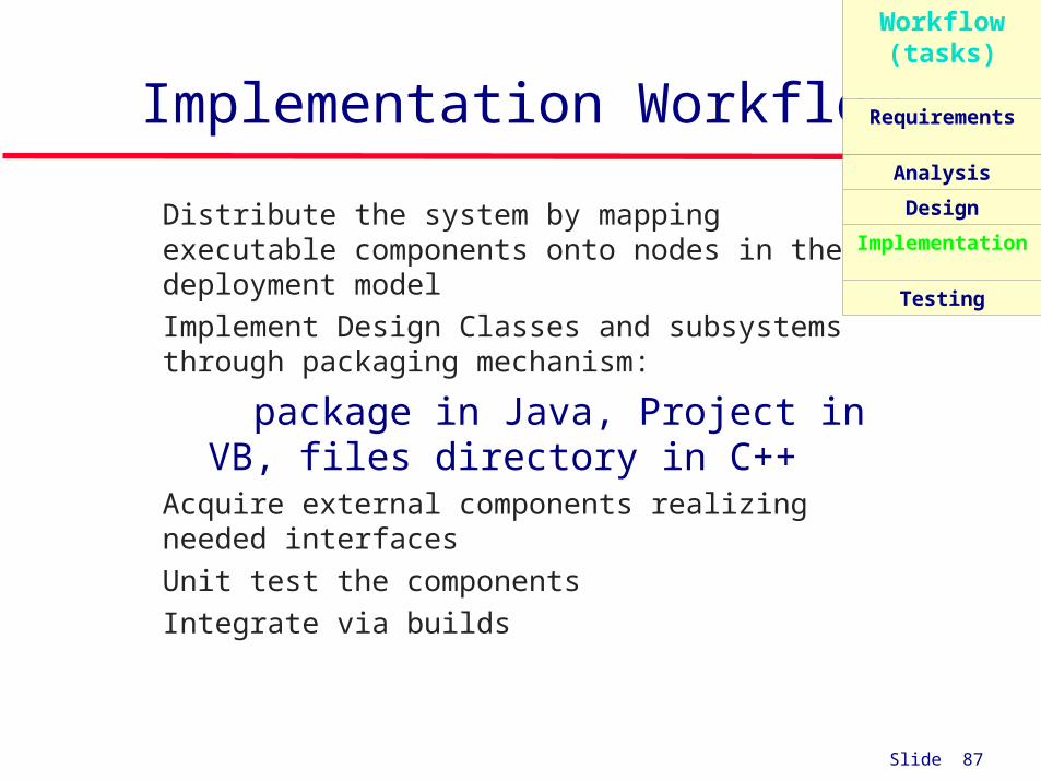
Implementation Workflow
Distribute the system by mapping executable components onto nodes in the deployment model
Implement Design Classes and subsystems through packaging mechanism:
• package in Java, Project in VB, files directory in C++
Acquire external components realizing needed interfaces
Unit test the components Integrate via builds
Workflow (tasks)
Requirements
Analysis
Design
Implementation
Testing

Slide 88
Test Workflow
Carried out in parallel with other workflows
Primary purpose• To increase the quality of the evolving
system
The test workflow is the responsibility of • Every developer and maintainer
• Quality assurance group
Workflow (tasks)
Requirements
Analysis
Design
Implementation
Testing

Slide 89
Test Workflow
Develop set of test cases that specify what to test in the system
• many for each Use Case• each test case will verify one scenario
of the use case• based on Sequence Diagram
Develop test procedures specifying how to perform test cases
Develop test component that automates test procedures
Workflow (tasks)
Requirements
Analysis
Design
Implementation
Testing

Slide 90
Deployment Workflow
Activities include• Software packaging• Distribution• Installation• Beta testing

Slide 91
Deployment Workflow
Producing the Software Output of implementation is tested executables. Must be associated with other artifacts to constitute a
complete product: Installation scripts User documentation Configuration data Additional programs for migration: data conversion.
In some cases:different executables needed for different user configurationsdifferent sets of artifacts needed for different classes of users:
new users versus existing users, variants by country or language

Slide 92
Deployment Workflow
Producing the Software (continued)
• For distributed software, different sets may have to be produced for different computing nodes in the network Packaging the Software
• Distributing the Software• Installing the Software• Migration• Providing Help and Assistance to Users• Acceptance

Slide 93
Iterations and Workflow
P re lim in a ry
Ite ra tio n (s)ite r.
# 1
ite r.
# 2
ite r.
# n
ite r.
#n + 1
ite r.
# n +2
ite r.
# m
ite r.
#m +1
Inception Elaboration Construction Transition
I te ra t io n s
Phases
Core Workflows
An iteration in theelaboration phase
Requirements
Design
Implementation
Test
Analysis

Slide 94
Supporting Workflows of The Unified Process

Slide 95
Software Project Management Plan
Once the client has signed off the specifications, detailed planning and estimating begins
We draw up the software project management plan, including• Cost estimate
• Duration estimate
• Deliverables
• Milestones
• Budget
This is the earliest possible time for the SPMP

Slide 96
Post delivery Maintenance
Post delivery maintenance is an essential component of software development• More money is spent on post delivery maintenance than on all other
activities combined
Problems can be caused by• Lack of documentation of all kinds
Two types of testing are needed• Testing the changes made during post delivery maintenance• Regression testing
All previous test cases (and their expected outcomes) need to be retained

Slide 97
Retirement
Software is can be made unmaintainable because• A drastic change in design has occurred• The product must be implemented on a totally new hardware/operating
system• Documentation is missing or inaccurate• Hardware is to be changed—it may be cheaper to rewrite the software
from scratch than to modify it
These are instances of maintenance (rewriting of existing software) True retirement is a rare event
It occurs when the client organization no longer needs the functionality provided by the product

Slide 98
What to Read…
• Dean Leffingwell, Don Widrig, Managing Software Requirements, Addison-Wesley, 2000, 491p.
• Alistair Cockburn, Writing Effective Use Cases, Addison-Wesley, 2001, 270p.
• Alan W. Brown (ed.), Component-Based Software Engineering, IEEE Computer Society, Los Alamitos, CA, 1996, pp.140.
• Ivar Jacobson, Magnus Christerson, Patrik Jonsson, and Gunnar Övergaard, Object-Oriented Software Engineering-A Use Case Driven Approach, Wokingham, England, Addison-Wesley, 1992, 582p.

Slide 99
Recommended Reading
Applying UML and Patterns: An Introduction to OOA/D and the Unified Process, Prentice Hall, 2002, by G. Larman
The Rational Unified Process - An Introduction, Addison-Wesley Professional, 2002, by its lead architect Ph. Kruchten