Slewing drive gear reducers
20
Industries Media No. 4083 EPS Slewing Drives Edition December 2011
description
Gear units for material handling application in any type of engineering
Transcript of Slewing drive gear reducers

IndustriesMedia No. 4083
EPSSlewing Drives
Edition December 2011

2 EPS - Slewing Drives - December 2011
Applications 3
Features and benefits 4
Quick selection (L2 T5), n2 = 15 min-1 6
Selection table 7
Selection, verifications and designation 8
Application factor KA and classification guidance 9
Dimensions 10
Installation and lubrication 11
Electric motor 12
Application data 14
Solutions in motion... 15
Contents

3EPS - Slewing Drives - December 2011
Applications
Civil Engineering Material and working elevators
Shipboard and deck cranes Tower cranes
Grab cranes
Stacker and reclaimerYaw and pitch drives for wind turbines
Container gantries

4 EPS - Slewing Drives - December 2011
Features and Benefits
• Wide range of planetary gear reducers, from 1 300 to 145 000 N m torque
• Modular design concept
➔ Right choice of the drive and cost effective solution for final customer tailored solutions
➔ Delivery flexibility and reliability
• Nodular cast iron housing and planet car-rier, full complement needle roller bearings
• ISO 12944 class paint on request• Grease and oil lubricant feasibility• Double seal and labyrinth options
➔ Highest standards in construction materials, maximum load strength
➔ Assuring the best coating for your drives
➔ Suitability for application demand
➔ Suitability for the most severe working conditions
➔ Easy installation and maintenance
• Case hardened ground gears designed and rated according to DIN 3990
• Gears with ground finish• Efficient, precise and upgraded machine
tools• Cutting edge industrial technology
➔ Clear and reliable performances ratings
➔ Performance, reliability, durability, long maintenance intervals
➔ Cost effectiveness, precision, low backlash, safety, environment-friendly machining
➔ High-quality standards, production flexibility
• Pinion teeth with full helix modification• Involute profile and helix modification cal-
culated and produced according to the op-erating load conditions
• High quality output pinion gear designed to specifications
➔ Improvement in contact patterns and nominal rating, achieving an optimal ring gear-pinion engagement
➔ Best fit following the major ring gear manufacturers recommendation
• High tech controlling instruments ➔ High quality and reliability standards
• Low Temperature Environment features• UL compliance certificate
➔ Conformity to most severe demands
➔ Conformity to U.S.A. specifications

5EPS - Slewing Drives - December 2011
• Main certifications available, as:
- ISO 9001 and 14000;- ATEX;- UL CSA;- Germanischer LIoyds.
➔ Flexibility and adaptability to specific project needs
• Competent assistance and technical sup-port during design/seletion activities
➔ Professional pre-sale service
➔ Calculation and selection tools
➔ Selection optimization: performance, reliability, cost-efficiency
Features and Benefits
• F.E.M. 1.001 ratings ➔ Easy selection in according to class of mechanism
• IEC electrical yaw brake motor wound and set for the specific application
• Anti-sticking design of the parking brake motor
• Braking torque adjustment• Customized power supply
➔ Complete one-supplier gearmotor package
➔ Constant braking performance
➔ Protection of the drive from external overloads, where as the customized winding protects the drive from motor overloads
➔ Simple machine design and achievement of more flexibility
• Global service ➔ Direct worldwide sales and service network
• 3 year warranty ➔ The reliability of a quality product made to last
➔ 3 year warranty since 1997

6 EPS - Slewing Drives - December 2011
Quick selection (L2 T5), n2 = 15 min-1
Actual transmission ratios i
Train ofgear
Nominal trans-mission ratio
Actual transmission ratio iGear reducer size
iN 100 200 300 500 800 1000 1300 2000 3000 4000 6000 8000 10000
3stages
50 50,5 50,5 50,5 50,5 53,1 53,1 50,1 50,1 55,2 49,1 55,2 54,1 48,160 59,6 59,6 59,6 59,6 62,6 62,6 59,1 59,1 62,0 58,6 65,9 64,6 57,4
71 70,2 70,2 70,2 70,2 73,7 73,7 69,6 69,6 73,1 69,0 74,0 72,5 68,585 86,6 86,6 86,6 86,6 92,4 92,4 87,2 – 91,6 86,5 85,4 83,7 87,9
100 102 102 102 102 107 107 101 – 106 100 103 107 113
125 128 128 128 128 134 134 127 – 123 129 132 129 134150 149 149 149 149 156 156 147 – – – 156 153 159180 179 179 179 179 189 189 178 – – – 192 – –
212 217 217 211 211 222 222 – – – – – – –250 255 255 – – – – – – – – – – –300 301 301 – – – – – – – – – – –
4stages
212 – – – – – – – – – 205 231 226 201250 – – – – 258 258 259 – 256 242 259 254 240300 – – 290 290 304 304 301 – 302 285 305 299 282
355 – – 357 357 375 375 354 – 378 357 382 375 354425 – – 421 421 442 442 418 418 439 414 444 435 411500 – – 528 528 535 535 523 523 550 519 512 502 527
600 – – 613 613 670 670 608 608 638 603 615 644 677710 – – 740 740 778 778 734 734 771 728 743 779 818850 – – 894 894 974 974 887 919 890 934 953 934 970
1 000 – – 1 120 1 120 1 177 1 177 1 111 – 1 075 1 129 1 131 1 109 1 151
Gear reducersize
Torques [N m]1) Radial Loads [N]1) 2)
MN2
Dynamic torqueM2stat
Static torqueFr2
Dynamic radial loadFr2 stat
Static radial load
(FEM L2 T5) (FEM L2 T5)
GR H GR HType Type Type Type
100 1 500 2 200 62 000 25 800 100 000 46 500200 2 700 4 000 62 000 – 100 000 –300 4 000 5 000 56 400 56 400 117 500 117 500
500 6 500 10 000 56 400 56 400 117 500 117 500800 10 000 15 000 73 000 77 400 140 000 148 000
1000 12 000 20 000 153 000 – 275 000 –
1300 15 000 30 000 180 000 180 000 312 500 312 5002000 25 000 40 000 180 000 180 000 312 500 312 5003000 30 000 72 000 298 000 – 700 000 –
4000 44 000 83 000 298 000 – 700 000 –6000 72 000 120 000 415 0003) – 910 0003) –8000 100 000 200 000 575 6003) – 1 400 0003) –
10000 125 000 250 000 666 2003) – 1 700 0003) –
Quick selectionTable 1
Table 2
1) For higher values, contact us.2) Values according to ISO 281, valid for overhung loads acting in the middle of the pinion facewidth «b» (table 6).3) See minimum value of dimension «G1»(table 6).
7EPS - Slewing Drives - December 2011
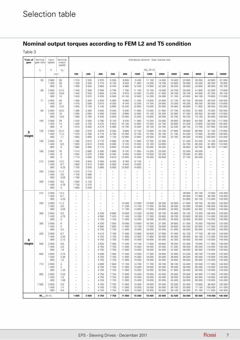
Nominal output torques according to FEM L2 and T5 condition
Selection table
Table 3
Train of gear
Nominal gear ratio
Input speed
Nominal output speed
Grandezza riduttore - Gear reducer size
iN n1 nN2 MN2 [N m]
min-1 100 200 300 500 800 1000 1300 2000 3000 4000 6000 8000 10000
3stages
50 2 800 56 1 310 2 320 2 970 5 300 6 600 9 430 11 100 14 500 18 400 23 800 35 000 43 600 61 000 50 1 400 28 1 420 2 500 3 770 6 130 8 530 11 800 14 200 18 700 23 800 30 800 45 300 56 300 78 900 50 900 18 1 490 2 620 3 960 6 440 9 880 12 400 14 900 22 200 28 200 36 600 53 800 66 900 93 700
60 2 800 47,5 1 340 2 360 3 560 5 790 7 780 11 100 13 100 16 300 20 700 28 400 41 800 52 000 72 800 60 1 400 23,6 1 440 2 540 3 840 6 240 9 570 12 000 14 400 21 000 26 700 36 700 54 000 67 200 94 100 60 900 15 1 520 2 670 4 030 6 560 10 100 12 600 15 200 24 900 31 700 43 600 64 100 79 800 112 000
71 2 800 40 1 360 2 400 3 630 5 900 9 060 11 400 13 600 22 800 27 100 40 700 56 500 69 200 104 000 71 1 400 20 1 470 2 590 3 910 6 350 9 740 12 200 14 700 24 600 33 200 46 200 68 200 85 500 119 000 71 900 12,5 1 550 2 720 4 100 6 680 10 200 12 900 15 500 25 900 34 900 48 600 71 900 98 500 125 000
85 2 800 33,5 1 390 2 460 3 640 6 040 9 280 11 600 14 000 21 900 27 700 42 600 61 800 70 300 100 000 85 1 400 16 1 500 2 650 4 000 6 500 9 980 12 600 15 100 25 200 32 900 47 400 69 300 83 400 119 000 85 900 10,6 1 580 2 780 4 200 6 840 10 500 13 200 15 800 26 500 35 700 49 700 73 100 93 600 128 000
100 2 800 28 1 420 2 500 3 780 6 140 9 430 11 800 14 200 20 000 26 800 38 900 64 500 88 700 117 000 100 1 400 14 1 530 2 700 4 070 6 620 10 100 12 800 15 300 22 700 30 600 44 200 70 800 102 000 125 000 100 900 9 1 610 2 830 4 270 6 960 10 700 13 400 16 100 24 700 32 200 48 100 74 700 107 000 132 000
125 2 800 22,4 1 460 2 570 3 870 6 300 9 660 12 100 14 600 23 100 27 800 39 600 66 900 81 100 115 000 125 1 400 11,2 1 570 2 760 4 170 6 790 10 400 13 100 15 700 26 100 31 100 44 200 72 900 92 000 128 000 125 900 7,1 1 650 2 900 4 380 7 130 10 900 13 800 16 500 27 400 32 700 46 500 76 900 100 000 134 000
150 2 800 19 1 480 2 610 3 170 5 680 8 790 11 600 13 700 22 200 – 31 400 54 400 74 100 100 000 150 1 400 9,5 1 600 2 810 3 500 6 280 9 720 13 300 15 100 24 600 – 34 700 60 200 81 900 110 000 150 900 6 1 680 2 950 3 710 6 650 10 300 14 000 16 000 26 000 – 36 800 63 700 86 700 117 000
180 2 800 16 1 510 2 660 3 280 5 880 9 100 11 900 14 200 23 000 – 32 500 56 500 – –180 1 400 8 1 630 2 870 3 590 6 430 9 950 13 600 15 500 25 200 – 35 600 61 800 – –180 900 5 1 710 3 000 3 800 6 810 10 500 14 300 16 400 26 600 – 37 700 65 400 – –
212 2 800 13,2 1 540 2 640 3 360 6 030 8 760 12 100 – – – – – – –212 1 400 6,7 1 660 2 910 3 660 6 560 9 940 13 800 – – – – – – –212 900 4,25 1 750 3 000 3 880 6 950 10 800 14 600 – – – – – – –
250 2 800 11,2 1 570 2 710 – – – – – – – – – – –250 1 400 5,6 1 700 2 980 – – – – – – – – – – –250 900 3,55 1 780 3 000 – – – – – – – – – – –
300 2 800 9,5 1 600 2 130 – – – – – – – – – – –300 1 400 4,75 1 730 2 370 – – – – – – – – – – –300 900 3 1 800 2 550 – – – – – – – – – – –
4stages
212 2 800 13,2 – – – – – – – – – 38 600 62 100 73 000 105 000 212 1 400 6,7 – – – – – – – – – 49 900 77 900 94 300 134 000 212 900 4,25 – – – – – – – – – 54 600 82 100 112 000 140 000
250 2 800 11,2 – – – – 10 400 13 000 15 800 26 200 30 900 41 600 69 700 82 000 126 000 250 1 400 5,6 – – – – 11 200 14 100 17 000 28 300 38 000 52 900 78 900 106 000 136 000 250 900 3,55 – – – – 11 700 14 800 17 900 29 800 39 900 55 600 83 300 118 000 143 000
300 2 800 9,5 – – 4 230 6 890 10 600 13 300 16 000 26 700 35 900 50 100 74 300 106 000 129 000 300 1 400 4,75 – – 4 560 7 420 11 400 14 300 17 300 28 800 38 700 53 800 80 500 114 000 139 000 300 900 3 – – 4 750 7 750 11 800 15 000 18 000 30 000 40 600 56 000 84 900 118 000 145 000
355 2 800 8 – – 4 330 7 050 10 800 13 600 16 300 27 300 36 800 51 300 76 300 109 000 132 000 355 1 400 4 – – 4 660 7 600 11 600 14 700 17 600 29 500 39 600 55 200 82 600 117 000 142 000 355 900 2,5 – – 4 750 7 750 11 800 15 000 18 000 30 000 41 600 56 000 85 000 118 000 145 000
425 2 800 6,7 – – 4 410 7 180 11 000 13 900 16 600 27 900 37 400 52 100 77 700 99 100 134 000 425 1 400 3,35 – – 4 750 7 730 11 800 14 900 17 900 30 000 40 300 56 000 84 100 112 000 145 000 425 900 2,12 – – 4 750 7 750 11 800 15 000 18 000 30 000 42 300 56 000 85 000 118 000 145 000
500 2 800 5,6 – – 4 520 7 360 11 200 14 100 17 000 28 600 38 300 53 400 79 000 111 000 138 000 500 1 400 2,8 – – 4 750 7 750 11 800 15 000 18 000 30 000 41 200 56 000 85 000 118 000 145 000 500 900 1,8 – – 4 750 7 750 11 800 15 000 18 000 30 000 42 500 56 000 85 000 118 000 145 000
600 2 800 4,75 – – 4 590 7 480 11 500 14 500 17 300 29 000 34 900 54 200 80 700 115 000 142 000 600 1 400 2,36 – – 4 750 7 750 11 800 15 000 18 000 30 000 38 600 56 000 85 000 118 000 145 000 600 900 1,5 – – 4 750 7 750 11 800 15 000 18 000 30 000 40 800 56 000 85 000 118 000 145 000
710 2 800 4 – – 4 690 7 640 11 700 14 700 17 700 29 700 36 100 55 400 82 500 117 000 145 000 710 1 400 2 – – 4 750 7 750 11 800 15 000 18 000 30 000 39 500 56 000 85 000 118 000 145 000 710 900 1,25 – – 4 750 7 750 11 800 15 000 18 000 30 000 41 800 56 000 85 000 118 000 145 000
850 2 800 3,35 – – 4 750 7 750 11 800 15 000 18 000 30 000 35 800 50 900 84 900 117 000 145 000 850 1 400 1,6 – – 4 750 7 750 11 800 15 000 18 000 30 000 38 500 54 800 85 000 118 000 145 000 850 900 1,06 – – 4 750 7 750 11 800 15 000 18 000 30 000 40 400 56 000 85 000 118 000 145 000
1 000 2 800 2,8 – – 4 750 7 750 11 800 15 000 18 000 30 000 33 200 52 000 70 800 96 400 130 000 1000 1 400 1,4 – – 4 750 7 750 11 800 15 000 18 000 30 000 36 700 55 900 77 100 105 000 141 000 1000 900 0,9 – – 4 750 7 750 11 800 15 000 18 000 30 000 39 100 56 000 81 700 111 000 145 000
M2max [N m] 1 800 3 000 4 750 7 750 11 800 15 000 18 000 30 000 42 500 56 000 85 000 118 000 145 000

8 EPS - Slewing Drives - December 2011
Selection, verifications and designation
Selection according to FEM 1.0011)
Required application data– Group and class of utilization (see tab. 5 as a guidance) for the mech-
anism involved.– Load spectrum of the required torque and speed.– Running conditions (accelerations-decelerations, frictional forces,
wind effect).– External drive data (pinion and ring-gear number of teeth and mod-
ule).– Gear reducer input speed (depending on motor type).
Required torqueStarting from running conditions (accelerations-decelerations, friction-al forces, wind effect) and load spectrum determine the maximum load:
SM = max (SM max I; SM max II)
where:SM max I = (SMF + SMA) · �m
is the maximum torque (combination of the most unfavourable actual values) during normal service without wind
SM max II = (SMF + SMA + SMW8) · �m
SM max II = (SMF + SMW25) · �m
is the maximum of the two torque values (each one as a combination of the most unfavourable actual values) during normal service with wind
SMF is mean torque generated by friction;SMA is mean torque generated by acceleration or deceleration;SMW8 is mean torque corresponding to a 80 N/m2 wind;SMW25 is mean torque corresponding to a 250 N/m2 wind;�m load amplification factor depending to mechanism group according to the fol-
lowing table:
Loadamplification
factor
Mechanism groupM1 M2 M3 M4 M5 M6 M7 M8
�m 1 1,04 1,08 1,12 1,16 1,2 1,25 1,3
Determine the gear reducer required output torque, as follows:
M2 required = SM / (ie · ηe)
where:
ie is the external drive gear ratio (given by z2 / z1, being z1 and and z2 the number of teeth of the pinion and of the ring gear respectively)
ηe is the the external drive efficiency (approx. 0,85)
Gear reducer size and transmission ratio selectionSelect in the selection table (see tab. 6) a gear reducer size (also, the train of gears and the nominal transmission ratio iN at the same time) on the basis of n2 max, n1 max ,such as:
MN2 � M2 required · KA
i � irequired
where:MN2 [N m] is the gear reducer nominal torque referred to FEM load spectrum class L2 and
utilization class T5 (see tab. 3);KA is the application factor (see tab. 4) which converts the gear reducer required
torque according to the actual class of utilization and load spectrum;n2 max [min-1] is the maximum speed required at the gear reducer low speed shaft (n2 application
max . ie);
n1 max [min-1] is the maximum gear reducer input speed (depending on motor type; eg.: for a IEC 4 poles motor, n1 = 1 400 min-1);
irequired gear reducer required transmission ratio (n1 max / n2 max).
VerificationsRadial loadVerify that the radial load on the gear reducer output pinion shaft when adjusted to spectrum class L2 and utilization class T5, is less than the reference value Fr2 given in tab. 1;
Dp . cosα � Fr2
M2 required . KA
. 2000
where:
Dp [mm] is the permissible pinion pitch diameter;
α [rad] pinion tooth pressure angle;
Fr2 [N] is the permissible radial load (L2 T5, n2 = 15 min-1) acting in the middle of the pinion facewidth and without axial load.
Dynamic overloadsStarts on full load (especially for high inertiae and low transmission ratios), brakings, shocks, cases of gear reducers where the low speed shaft becomes motor due to the inertiae of driven machine, usually generate overloads. In these cases it is necessary to verify that the maximum peak torque is always lower than M2max (see tab. 3).
+ M2 required � M2maxMN J + J0( )M2 start = . M2 available - M2 required
Mstart . J
- M2 required � M2maxη J + J0( )M2 brake = . i + M2 required
Mf . J
where:M2 max [N m] is maximum dynamic torque;M2 available [N m] is output torque due to the motor’s nominal power;Mf [N m] is the braking torque at the gear reducer input shaftMstart / MN is the ratio of motor peak.J0 [kg m2] is the moment of inertia (of mass) of the motor;
J [kg m2] is the external moment of inertia (of mass: coupling, driven machine, ect) referred to the motor shaft,
η is the gear reducer effi ciency:≈ 0,91 (3 stages) or ≈ 0,88 (4 stages).
NOTE: when seeking to verify that starting torque is suffi ciently high for starting, take into account starting friction, if any, in evaluating M2 required.
Static loadVerify that the gear reducer static torque and static radial load (see tab.1) are higher than static braking torque, and static overhung load (referred to the gear reducer low speed shaft):
M2 stat � Mf · i / η
η . Dp. cosα Fr2 stat �
Mf . i . 2000
Designation example:EPS 1300 H3 - 850 - R xx - 19-200
IEC motor coupling dimensions (∅d-∅P), see pag. 13Pinion code (rel. to module, teeth nr.), see pag. 11
Output shaft design (pinion)
Transmission ratio
Output flange, nr. of stages
Size
Planetary gearmotors for slewing drives
1) For complete selection please refer to FEM section I 3rd edition.
Also available, on request:- right angle shaft gear reducer;- 5 stages gear reducer.

9EPS - Slewing Drives - December 2011
Class of utilization
Class of load spectrum
T2 T3 T4 T5 T6 T7 T8
400h < T2 � 800h 800h < T3 � 1 600h 1 600h < T4 � 3 200h 3 200h < T5 � 6300h 6300h < T6 � 12500h 12500h < T7 � 25000h 25000h < T8 � 50000h
L10 < km � 0,125
M1 M2 M3 M4 M5 M6 M70,75 0,80 0,86 0,93 1,00 1,08 1,16
L20,125 < km � 0,25
M2 M3 M4 M5 M6 M7 M80,81 0,87 0,93 1,00 1,08 1,16 126
L30,25 < km � 0,5
M3 M4 M5 M6 M7 M8 M80,89 0,96 1,03 1,11 1,19 1,29 1,38
L40,5 < km � 1
M4 M5 M6 M7 M8 M8 M80,97 1,04 1,12 1,21 1,30 1,40 1,51
Load spectra (examples)
Application factors KA and mechanism groups
Application factor KA and classification guidance
Type of applianceDesignation
Particulars conceringnature of use
Type of mechanism
Slewing Hoisting Luffing Traverse Travel
Erection cranes – M2 – M3 M2 – M3 M1 – M2 M1 – M2 M2 – M3
Stocking and reclaiming transporter Hook duty M4 M5 – M6 – M4 – M5 M5 – M6
Stocking and reclaiming transporter Grab or magnet M6 M7 – M8 – M6 – M7 M7 – M8
Workshop cranes M4 M6 – M4 M5
Overhead travelling cranes, pigbreaking cranes, scrapyard cranes Grab or magnet M6 M8 – M6 – M7 M7 – M8
Bridge cranes for unloading, bridge cranes for containersOther bridge cranes (with crab and/or slewing jib crane)
a) Hook or spreaded dutyd) Hook duty
M5 – M6M4 – M5
M6 – M7M4 – M5
M3 – M4–
M6 – M7M4 – M5
M4 – M5M4 – M5
Bridge cranes for unloading, bridge cranes (with crab and/or slewing jib crane) Grab or magnet M5 – M6 M8 M3 – M4 M7 – M8 M4 – M5
Drydock cranes, shipyard jib cranes, jib cranes for dismantling Hook duty M4 – M5 M5 – M6 M4 – M5 M4 – M5 M5 – M6
Dockside cranes (slewing, on gantry, etc.), floating cranes and pontoon derricks Hook duty M5 – M6 M6 – M7 M5 – M6 – M3 – M4
Dockside cranes (slewing, on gantry, etc.), floating cranes and pontoon derricks – M6 – M7 M7 – M8 M6 – M7 – M4 – M5
Floating cranes and pontoon derricks for very heavy loads (usually greater than 100t) – M3 – M4 M3 – M4 M3 – M4 –
Deck cranes Hook duty M3 – M4 M4 M3 – M4 M2 M3
Deck cranes Grab or magnet M3 – M4 M5 – M6 M3 – M4 M4 – M5 M3 – M4
Tower cranes for building – M5 M4 M4 M3 M3
Derricks – M1 – M2 M2 – M3 M1 – M2 – –
Railway cranes allowed to run in train – M2 – M3 M3 – M4 M2 – M3 – –
Mobil cranes Hook M2 – M3 M3 – M4 M2 – M3 – –
Group classification guidance
Table 4
Table 5

10 EPS - Slewing Drives - December 2011
Dimensions
EPS Gear reducers
Dimensions Output pinion shaft
DS F G1 M N N0 P S X1 L b Dpmin EXZ
∅×nr. ∅ ∅ ∅ ∅ ∅ 3 stages 4 stages module facewidth ∅
size type mm mm mm mm mm mm mm mm mm mm mm mm mm
DIN 5482 E9
100 H 50×45 10,5×8 6 165 – 110 f7 185 12 200 232 282 5 – 6 56 80 –100 GR 58×53 10,5×4 162 240 160 h6 150 h6 275 32 200 176,5 226,5 5 – 6 68 98 0,5200 GR 58×53 17,5×4 162 240 160 h6 150 h6 275 32 200 188,5 238,5 6 – 8 68 98 0,5300 H 70×64 12,5×10 39 245 – 175 f7 272 20 240 279 329 6 – 8 90 110 –300 GR 70×64 10,5×8 142 224 200 g7 195 g7 244 63 240 176 226 8 90 110 –500 H 70×64 12,5×10 40 245 – 175 f7 272 20 240 306 356 8 – 10 90 120 –500 GR 70×64 10,5×8 142 224 200 g7 195 g7 244 78 240 203 253 8 – 10 90 120 –800 H 80×74 17×12 40 250 – 200 f7 280 22 280 349 399 10 – 12 90 120 –800 GR 80×74 12,5×10 184 260 240 g7 200 g7 280 80 280 205 255 10 – 12 90 120 –
1000 GR 100×94 17×16 303 350 278 g7 228 g7 380 30 315 205,5 255,5 12 110 160 0,751300 H 100×94 16,5×20 57 295 – 250 f7 325 30 353 416,5 466,5 12 – 14 110 160 –1300 GR 100×94 17×18 233 325 290 g7 250 g7 363 96 363 240,5 290,5 12 – 14 110 160 1,52000 H 100×94 17×18 57 295 – 250 f7 325 30 353 438,5 488,5 12 – 14 – 16 110 160 -–2000 GR 100×94 17×18 233 325 290 g7 250 g7 363 118 363 262,5 312,5 12 – 14 – 16 110 160 0,5
DIN 5480 9H
3000 GR 140×5 22×24355 min 475 430 h7 340 h7 515 40 428 341 383,5 16 – 18 – 20 150 224 2,5 – 51 855 max
4000 GR 140×5 22×24355 min 475 430 h7 340 h7 515 40 428 362 416,5 16 – 18 – 20 150 224 2,5 – 51 855 max
6000 GR 160×5 26×24355 min 525 465 h7 340 h7 575 45 445 406 460,5 16 – 18 – 20 150 300 2,5 – 51 855 max
8000 GR 200×5 26×24710 min 630 580 h7 510 h7 690 50 542 335,5 403,5 20 – 22 170 300 51 810 max
10000 GR 200×5 33×24730 min 680 630 h7 510 h7 740 50 542 335,5 403,5 20 – 22 – 24 170 300 51 830 max
Double pilot extended output supportFront fixing flange output support
Table 6
(page 13)(page 13)

11EPS - Slewing Drives - December 2011
Manufacturer PAO synthetic oilISO VG 150 ... 460
mineral oilISO VG 150 ... 460
AGIP Blasia SX 220 ... 460 BlasiaARAL Degol PAS Degol BG
BP Enersyn EPX Energol GR XPKLÜBER Klübersynth GEM4 Klüberoil GEM1
MOBIL Mobilgear SHC XMPMobilgear 600 XPMobilgear XMP
SHELL Omala HD OmalaTOTAL Carter EP SH Carter EP
Speed n2min-1
Ambient temperature1) [°C]mineral oil
0 ÷ 20 10 ÷ 40
� 140 150 220140 ÷ 2,0 220 320
� 2,0 320 460
ISO viscosity gradeMean kinematic viscosity [cSt] at 40 °C.
1) Peaks ± 10°C are acceptable.
Oiltemperature [°C]
Oil-charge interval [h]synthetic oil mineral oil
� 65 12 500 5 60065 ÷ 80 9 000 2 80080 ÷ 95 6 300 1 400
The main lubricant manufacturers as well as the ISO viscosity grade to be used are stated in the following tables. Use only lubricants with EP (extreme pressure) additives.Polyglycol basis synthetic lubricants may not mixed with other type's lubricants (mineral and PAO lubricants). Before any lubricant type change, carefully clean the gear reducer.Never mix different makes of synthetic oil; if oil-change involves switching to a type different from that used hitherto, then give the gear reducer a through clean-out.
Oil-change intervals assume pollution-free surroundings. When heavy overloads are present, halve the values.Independently from running times, change the oil as follows:– every 1 ÷ 2 years, for mineral oil;– every 2 ÷ 4 years, for synthetic oil.
LubricationInstallationTo ensure proper functioning and optimum transfer of power between the gear reducers and the driven gear, the gear reducers requires a rigid connection construction that is resistant to torsion. The form and position tolerances listed below must be met.
Dimension tolerances of the assembly construction for slewing gear reducers
Dimension tolerances of the assembly construction for slewing gear reducers
Installation and lubrication
Output pinionDesign features:– full helix modification– ground finish– tip relief– gear accuracy grade DIN 8– addendum modification coefficient x = 0,5
Pinion designation example: R PC (pinion with m = 8, z = 12), see also page 8.
Module5 6 7 8 9 10 11 12 14 16 18 20 22 24
Code for designation M N O P Q R S T U V W X Y Z
Nr. of teeth10 11 12 13 14 15 16 17 18 19 20 21 22 23 24 25 26 27 28 29 30 31 32
Code for designation A B C D E F G H I K L M N O P Q R S T U V W X

12 EPS - Slewing Drives - December 2011
Electric motor
Thanks to its high quietness, progressivity and dy-namic characteristics, it is specifically suitable for coupling with gearmotor minimizing the dynamic overloads deriving from starting and braking phases (especially in case of motion reversals) and maintaining a very good braking torque value.The excellent operation progressivity - when starting and braking - is assured by the brake anchor which is less quick in the impact (compared to a.c. HBF types) and by the slight quickness of d.c. brakes.Offering a comprehensive range of accessories and non-standard designs in order to satisfy all possible gearmotor application fields (e.g. IP 56, IP 65, flywheel, encoder, independent cooling fan, independent cool-ing fan and encoder, double extension shaft, integrated motor-inverter, etc.).
* on request.
HBZAsynchronous three-phase brake motor with d.c. brake
HBFAsynchronous three-phase brake motor with a.c. brake
The high reactivity typical of a.c. brake and the high braking capacity make this brake motor particularly suitable for heavy duties requiring quick brakings and a high number of operations (e.g.: lifts with high fre-quency of starting, usually for size � 132, and/or for jog operations).Vice versa, its very high dynamic characteristics (ra-pidity and frequency of starting) are not advisable for the use in gearmotor coupling, especially when these features are not strictly necessary for the application (avoiding useless overloads on the whole transmission).Comprehensive range of accessories and non-stand-ard designs in order to satisfy all application needs of gearmotors (in particular for HBF: IP 56, IP 65, encoder, independent cooling fan, independent cooling fan and encoder, double extension shaft, integrated motor-in-verter, etc.).
* on request.HBVAsynchronous three-phase brake motor with d.c. safety brake
Featuring maximum economy, very reduced overall dimensions and moderate braking torque, it is suit-able for the coupling with gearmotor and can be ap-plied as brake for safety or parking stops (e.g. cutting machines) and for operations at deceleration ramp end during the running with inverter.The standard cast iron fan supplies a flywheel effect in-creasing the very good progressivity of starting and brak-ing (typical of d.c. brake) being particularly suitable for «light» traverse movements.
Multi-voltage brake rectifi er (patent pending) which gen-erates a preset constant output voltage independent from input supply (and from its fl uctuations) and, com-pared to a usual rectifi er, reduces the voltage to keep the brake released.- Possibility to supply the brake at 230, 400 or 460 V a.c. indifferently;
- Higher steadiness of brake characteristics, lower en-ergy consume, lower coil heating and lower braking delay;
- No special brake coil;- Ready to use in NEMA environment;- Max availability and stock fl exibility.
Multi-voltage brake rectifi er

13EPS - Slewing Drives - December 2011
Motor size Main coupling dimensions
UNEL 13117-71(DIN 42677 BI 1.A-65, IEC 72.1)
Shaft endØ d × E
Flange Ø PB5
63 11 × 23 14071 14 × 30 16080,90 B5R 19 × 40 20090, 100 B5R, 112 B5R 24 × 50 200
100, 112, 132 B5R 28 × 60 250132, 160 B5R 38 × 80 300160 42 × 110 350180, 200 B5R 48 × 110 350200 55 × 110 400225, 250 B5R 60 × 140 450250 65 × 140 550280, 315S B5R 75 × 140 550315 80 × 170 660
Electric motor
Train ofgear
IECframe size
Gear reducer sizelength variation ∆L
P d 100 200 300 500 800 1000 1300 2000 3000 4000 6000 8000 10000Ø Ø
3stages
56 120 9 20 – – – – – – – – – – – –63 140 11 20 20 – – – – – – – – – – –71 160 14 20 20 20 – – – – – – – – – –80 200 19 30 30 30 – – – – – – – – – –90 200 24 30 30 30 30 30 30 30 48 – – – – –
100, 112 250 28 48 48 48 30 48 48 48 61 61 61 – – –132 300 38 – – – 48 61 61 61 127 127 127 – – –160 350 42 – – – 61 127 127 127 127 127 127 – – –180 350 48 – – – 127 – 127 127 – – –200 400 55 – – – – – – – – 145 145 198 – –225 450 60 – – – – – – – – – 145 198 – –250 550 65 – – – – – – – – – – 198 198 198
4stages
56 120 9 20 20 20 20 – – – – – – – – –63 140 11 20 20 20 20 20 – – 20 – – – – –71 160 14 20 20 20 20 20 20 20 30 – – – – –80 200 19 – 30 30 30 30 30 30 30 30 30 – – –90 200 24 – – – 30 30 30 30 48 48 48 48 48 –
100, 112 250 28 – – – 48 48 48 – 61 61 61 61 61132 300 38 – – – – – – – – 127 127 127 127 127160 350 42 – – – – – – – – – 127 127 127 127180 350 48 – – – – – – – – 127 127200 400 55 – – – – – – – – – – – 145 145225 450 60 – – – – – – – – – – – – 145250 550 65 – – – – – – – – – – – –
(page 10)

14 EPS - Slewing Drives - December 2011
Application data template
Application data
Customer :
Application description:
Mechanism (FEM 1.001 1998.10.01):
FEM Class: M
Load Spectrum Class: L
Running time Class: T
Torques at pinion:
Output torque at pinion MN2required [N m]
Has �m factor been included in MN2required yes no
Peak / Static torque at pinion M2stat [N m]
Pinion speed n2 [min-1]
Maximum working angle (referrd to gearbox workimg position) [°]
Relevant Geometry (please fill-out relevant dotted lines):
Type H Type GR
Mounting positions
B5 V1 V3
UT.C 1474

15EPS - Slewing Drives - December 2011
Application data template
Pinion One piece solid Fitted on splined shaft
m modulus [mm]
Z1 N°. of teeth [-]
x.m profile correction [mm]
b1 facewidth [mm]
Material
Heat treatment
Hardness
Slew gears data:
Centre distance (Pinion - Slew Ring) a: [mm]
Slew Ring (Ring Bearing) Internal toohing
External toothing
m modulus [mm]
Z2 N°. of teeth [-]
x.m profile correction [mm]
b2 facewidth [mm]
Material
Heat treatment
Hardness
Electric Motor:
Power: [kW]; Voltage: [V]; Frequency: [Hz]; N° poles: [-];
Frequency Control device: yes no
Motor brake: yes no
Dynamic braking torque: [N m] Static braking torque: [N m]
Hydraulic Brake: yes no
Dynamic braking torque: [N m] Static braking torque: [N m]
Hydraulic Brake:
Brand and type: Shaft type:
Displacement: [cc]; Max pressure: [MPa]; Working pressure: [MPa];
Notes and Remarks:

16 EPS - Slewing Drives - December 2011
Notes

17EPS - Slewing Drives - December 2011
Pagina lasciata intenzionalmente biancapage intentionally left blank

18 EPS - Slewing Drives - December 2011
List of updates (Cat. EPS - Edition April 2011 available onwww.rossi-group.com)
Page 6: Updates quick selection table.Page 14 Updated slewing drive datasheet.
List of updates (Cat. EPS - Edition December 2011 available onwww.rossi-group.com)
Pag. 14, 15: Updates application data template.
Index of revisions

19EPS - Slewing Drives - December 2011
Solutions in motion...
History and know-howFor more than 50 years, Rossi has been developing its busi-ness in the most demanding applications to become one of the world’s leading gearmo-tor manufacturers suitable for critical machines. Even in the toughest environment, Rossi is recognized for providing state of the art technology, solid value, and commitment to its custom-ers.Whatever gear reducer or gear motor your technology may need, Rossi's qualifi ed staff is at your disposal to provide as-sistance, support, and innova-tive solutions during the design phase.Customer tailored solutions may
be found to maximize performance, while, at the same time, minimizing the overall machine cost.
More than: • 50 years of experience
and success in the power transmission field
• 20 years in windindustry
• 100 000 wind drives installed
enables Rossi to offer Customers a comprehen-sive product range includ-ing helical, bevel, worm, planetary gear reducers and gearmotors; gear reducer for heavy appli-cations, electric motors,
servomotors, inverters, servoinverters, and on board inverter drives.
History and know-howFor more than 50 years, Rossi
ness in the most demanding applications to become one of
tor manufacturers suitable for critical machines. Even in the
environment, Rossi is recognized for providing state of the art technology, solid value,
Whatever gear reducer or gear motor your technology may need, Rossi's qualifi ed staff is
tive solutions during the design
Customer tailored solutions may be found to maximize performance, while, at the same time, minimizing
•
•
•
enables Rossi to offer Customers a comprehen-sive product range includ-ing helical, bevel, worm, planetary gear reducers and gearmotors; gear reducer for heavy appli-cations, electric motors,
Product liability, application considerationsThe Customer is responsible for the correct selection and application of product in view of its industrial and/or commercial needs, unless the use has been recommended by technical qualified personnel of Rossi, who were duly informed about customer’s application purposes. In this case all the necessary data required for the selection shall be communicated exactly and in writing by the Customer, stated in the order and confirmed by Rossi. The Customer is always responsible for the safety of product applications. Every care has been taken in the drawing up of the catalog to ensure the accuracy of the information contained in this publication, however Rossi can accept no responsibility for any errors, omissions or outdated data. Due to the constant evolution of the state of the art, Rossi reserves the right to make any modification whenever to this publication contents. The responsibility for the product selection is of the customer, excluding different agreements duly legalized in writing and undersigned by the Parties.
Registered trademarksCopyright Rossi S.p.A.Subject to alterationsPrinted in ItalyPublication data4083FLY.EPL-en1211HQM
Rossi S.p.A.
Via Emilia Ovest 915/A41123 Modena - ItalyPhone +39 059 33 02 88fax +39 059 82 77 74e-mail: [email protected]
AustraliaRossi Gearmotors Australia Pty. Ltd.AU - Perth WAPhone +61 8 94557399fax +61 8 94557299e-mail: [email protected] BeneluxHabasit Netherlands B.V.NL - NijkerkPhone +31 33 247 20 30Fax: +31 33 246 15 99e-mail: [email protected]
CanadaRossi GearmotorsDivision of Habasit Canada LimitedCA - Oakville, OntarioPhone +1 905 8274 131fax +1 905 8252 612e-mail: [email protected]
ChinaRossi Gearmotors China P.T.I.CN - ShanghaiPhone +86 21 3350 5345fax +86 21 3350 6177e-mail: [email protected]
DenmarkHabasit ABDK - 3400 HillerødPhone +45 48 28 80 87fax +45 48 28 80 89e-mail: [email protected]
France Rossi Motoréducteurs SARLF - Saint PriestPhone +33 472 47 79 30fax +33 472 47 79 49e-mail: [email protected]
GermanyRossi GmbHD - DreieichPhone +49 0 172 6570440 e-mail: [email protected]
India Rossi Gearmotors Pvt. Ltd.IN - CoimbatorePhone +91 422 262 7879fax +91 422 262 7214e-mail: [email protected]
New Zealand Rossi Gearmotors New Zealand Ltd.NZ - AucklandPhone +61 9 263 4551fax +61 9 263 4557e-mail: [email protected]
PolandRossi Polska Sp.z o.o.PL-WrocławPhone: +48 500 418 505e-mail: [email protected]
Portugal Rossi Motorreductores S.L.E - Viladecans (Barcelona)Phone +34 93 6377248fax +34 93 6377404e-mail: [email protected]
Spain Rossi Motorreductores S.L.E - Viladecans (Barcelona)Phone +34 93 6377248fax +34 93 6377404e-mail: [email protected] www.rossimotorreductores.es
Sweden Habasit ABS - 430 63 HindåsPhone +46 301 226 00fax +46 301 226 01e-mail: [email protected]
TaiwanHabasit Rossi (Taiwan) LTD.TW - Taipei HsienPhone +886 2 22670538fax +886 2 22670578e-mail: [email protected]
Rossi Turkey & Middle EastTR - Çiğli - IzmirPhone +90 5303007772e-mail: [email protected]
United Kingdom Habasit Rossi LimitedUK - CoventryPhone +44 2476 644646fax +44 2476 644535 e-mail: [email protected] www.habasitrossi.co.uk
United StatesRossi GearmotorsA Division of Habasit AmericaUS - SuwaneePhone +1 800 931 2044fax +1 678 288 3658e-mail: [email protected]