SLEWING BEARNG
31
ISO9001 & ISO14001 & OHSAS18000 Certified PRODUCT CATALOGUE TENSUN MACHINERY CO., LTD SLEWING BEARNG Rotational Solutions
Transcript of SLEWING BEARNG

ISO9001 & ISO14001 & OHSAS18000 Certified
PRODUCT CATALOGUE
TENSUN MACHINERY CO., LTD
SLEWING BEARNG
Rotational Solutions
2
Global Competitive Cost
& World Class Quality
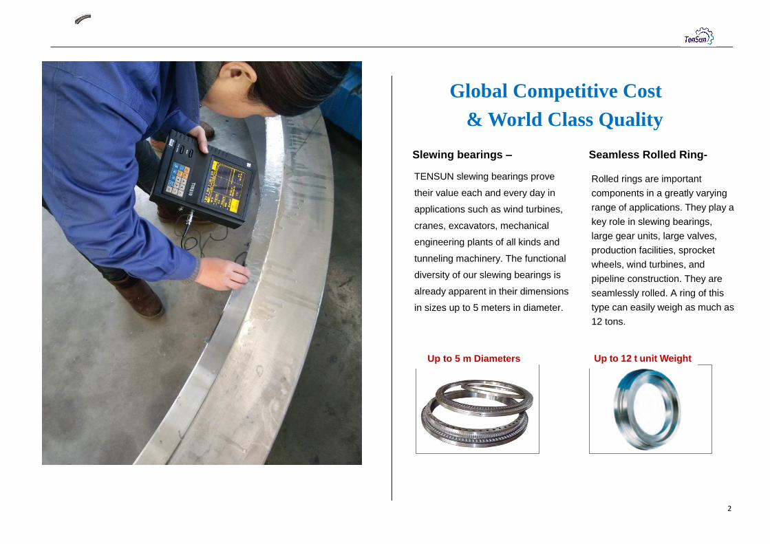
Slewing bearings – Seamless Rolled Ring-
TENSUN slewing bearings prove
their value each and every day in
applications such as wind turbines,
cranes, excavators, mechanical
engineering plants of all kinds and
tunneling machinery. The functional
diversity of our slewing bearings is
already apparent in their dimensions
in sizes up to 5 meters in diameter.
Rolled rings are important
components in a greatly varying
range of applications. They play a
key role in slewing bearings,
large gear units, large valves,
production facilities, sprocket
wheels, wind turbines, and
pipeline construction. They are
seamlessly rolled. A ring of this
type can easily weigh as much as
12 tons.
Up to 12 t unit Weight Up to 5 m Diameters

3
Construction machinery
Tensun slewing bearings are used in construction machinery of
all types the world over. The construction engineering, road
construction and maintenance, flow type lifting handling operation
and various construction projects need necessary for
comprehensive mechanized construction engineering machinery
and equipment. The slewing bearing is the key in this application.
Cranes
Whether port, off shore or construction cranes – Tensun supplies
right slewing bearing for every application.
These bearings are customer designed and built in close
cooperation with each customer.
Our target is build long term relationship with Customers
Energy
Our commitment in the field of energy technology has made us a
reliable partner for the wind, solar, and hydropower industries
since their beginnings.
Designed for utmost reliability and long-lasting quality,
The slewing bearings and rings from Tensun are core parts.
Transport and materials handling technology
Tensun provides solutions for each special, individual need in the
field of transport and materials handling technology.
When it comes to tunnel engineering, we deliver the ideal
cutting-head bearing for every type rock.
Mechanical engineering
Tensun slewing bearing is widely used in Mechanical engineering
field. Optimal design, excellent weight-to-power ratio,
open centers, and integrated gearing make slewing bearings the
ideal structural components and be reliable partner.

4
CONTENT
1. Coding System------------------------------------------------------------5
2. Basic Knowledge---------------------------------------------------------6
2.1 Structure-----------------------------------------------------------------6
2.2 Raceway & Gear Hardening--------------------------------------7
2.3 Material-----------------------------------------------------------------8
2.4 Slewing Bearing Selection-----------------------------------------9
2.5 Tolerance--------------------------------------------------------------11
3. Single-row four-point contact ball slewing bearing-----------12
4. Double-row ball slewing bearing------------------------------------18
5. Crossed roller slewing bearing---------------------------------------21
6. Three-row roller slewing bearing-------------------------------------24
7. Light type slewing bearing----------------------------------------------27
8. Load curve for slewing bearings--------------------------------------31

5
1. Coding System
0 1 4 0 1 2 5 0 0 0 X X X X
2- Involute column outer teeth & bigger module
3- Involute column inner teeth & smaller module
4- Involute column inner teeth & bigger module
02-Double-row ball type
11-Singel-row cross roller slewing bearing
13-Three-row roller slewing bearing
L1-Light profile ball contact slewing bearing
Structure type
0- No teeth
1- Involute column outer teeth & small module
01-Single-row four point ball contact type
01- inner & outer ring are screwed hole
2-Speical type
Transmission type
02- Outer ring are screwd hole, innerring through hole
03- Outer ring are screwed hole, inner ring are through hole
Mounting type 0-Standard port
1-Standard type with a stop opening
Raceway center dim (mm)
Roller dim(mm)
Product Coding System JB/T2300-1999
1 0
Mounting hole type 00- Inner & outer ring are through the hole
Internal counting
6
2. Basic Knowledge
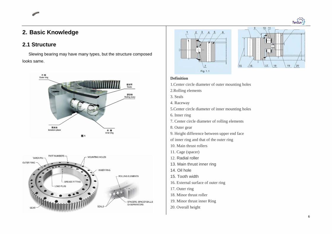
2.1 Structure
Slewing bearing may have many types, but the structure composed
looks same.
Definition
1.Center circle diameter of outer mounting holes
2.Rolling elements
3. Seals
4. Raceway
5.Center circle diameter of inner mounting holes
6. Inner ring
7. Center circle diameter of rolling elements
8. Outer gear
9. Height difference between upper end face
of inner ring and that of the outer ring
10. Main thrust rollers
11. Cage (spacer)
12. Radial roller
13. Main thrust inner ring
14. Oil hole
15. Tooth width
16. External surface of outer ring
17. Outer ring
18. Minor thrust roller
19. Minor thrust inner Ring
20. Overall height

7
2.2. Raceway & Gear Hardening
Raceway Hardening
The bearing types described here are provided with induction-hardened
raceways. This ensures good reproducibility of hardening specifications
and, therefore, consistent quality. The hardening coils used have been
adapted to the various raceway designs. They are configured so as to
guarantee the load capacities specified for the respective rolling element
sizes.
Our patented coil shape ensures a good hardness pattern in the raceways
and in the transition radii in three-row roller bearings.
Hardness of Raceway of ring after hardened is 55HRC~62HRC,
Quenching layer ≥3 mm.
Gear Hardening
The heat treatment of the gear is in generally normalizing or hardening and
tempering state. According to application, the gear can be treated full teeth
quench or tooth surface quench only and tooth surface and tooth root
quench.
Raceways in a single-row
ball
Raceways in a single-row
roller Raceways of a nose ring in a
double-row ball bearing
Raceway of a supporting ring in a
double-row ball bearing slewing ring
Raceways of a nose ring in a
three-row roller bearing slewing

8
2.3 Material
The basis of bearing quality is material, which, has great influence on
bearing performance, life and reliability. The rolling surface of components
carries periodical alternating loads during operation, extremely high
contact stress is generated on the contact position due to the small contact
area between components will fatigue under the repeated actions of the
stress, which results on the fatigue flake. Meanwhile, both rolling friction
and sliding friction exist at the component contact position. Therefore, the
bearing material should have the following performances:
High contact fatigue intensity.
High flexibility limit.
High hardness obtained.
Good abrasion resistance and anticorrosion.
Good structure stability.
Good machining property.
Good impact resistance.
Inner ring and outer ring
Tensun use 50Mn or 42CrMo for slewing bearing rings.
The hardness of the working surfaces such as the raceway surface may
have a surface hardness up to 55-60 HRC after hardening.
Ball & Roller
Materials for rolling elements are selected according China standard ball
GB/T 308 and roller GB/T 4662 which are produced from GCr1 OR
GCr15SiMn.The heat treatment specification is accordance with
GB/T1255.
DW/mm Grade of Ball
≤30 G40
>30~50 G60
>50 G100
Seal
The sealing material used in TENSUN slewing bearing is grease/oil
resistant and manufactured from nitrile rubber, and fluorine rubber etc. The
seals are produced in accordance with HG/T 2811 (Material for Lip Type
Seal Ring of Slewing Shaft). Other material also can be used according
customer requirements. Please contact TENSUN as needed.
OPERATING CONDITIONS RANGES
"Normal" - 25° C + 70°C NITRILE-BASED elastomer
"Extreme" 0< - 30° C; + 70°C<0<
200°C FLUORE-based ELASTOMER
"Special" Various physical or
chemical aggressive agents
NITRILE-BASED
modified or others
Spacer Block
TENSUN standard product use the spacer block produced by Polyamide
1010, which is made comply with HG/T 2349.
C Si Mn Mo Cr Ni S P Cu
50 Mn 0.48~0.56 0.17~0.37 0.70~1.00 --------- ≤0.25 ≤0.25 ≤0.035 ≤0.035 ≤0.25
materialchemical composition %
C Si Mn Mo Cr Ni S P Cu
42CrMo 0.38~0.45 0.17~0.37 0.50~0.80 0.15~0.25 0.90~1.2 ≤0.30 ≤0.035 ≤0.035 ≤0.30
chemical composition %material
9
2.4 Bearing Selection
General:
The final and binding selection of a large-diameter slewing bearing is
principally made by us.
Selection determines the correct dimensioning of bearing races, gearing
and bolt connections.
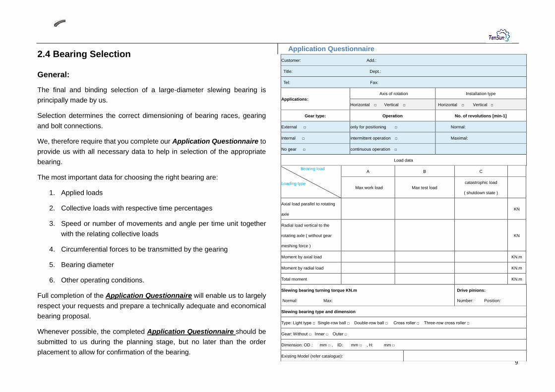
We, therefore require that you complete our Application Questionnaire to
provide us with all necessary data to help in selection of the appropriate
bearing.
The most important data for choosing the right bearing are:
1. Applied loads
2. Collective loads with respective time percentages
3. Speed or number of movements and angle per time unit together
with the relating collective loads
4. Circumferential forces to be transmitted by the gearing
5. Bearing diameter
6. Other operating conditions.
Full completion of the Application Questionnaire will enable us to largely
respect your requests and prepare a technically adequate and economical
bearing proposal.
Whenever possible, the completed Application Questionnaire should be
submitted to us during the planning stage, but no later than the order
placement to allow for confirmation of the bearing.
Application Questionnaire
Customer: Add.:
Title: Dept.:
Tel: Fax:
Applications:
Axis of rotation Installation type
Horizontal □ Vertical □ Horizontal □ Vertical □
Gear type: Operation No. of revolutions [min-1]
External □ only for positioning □ Normal:
Internal □ intermittent operation □ Maximal:
No gear □ continuous operation □
Load data
Bearing load Loading type
A B C
Max work load Max test load
catastrophic load
( shutdown state )
Axial load parallel to rotating
axle
KN
Radial load vertical to the
rotating axle ( without gear
meshing force )
KN
Moment by axial load KN.m
Moment by radial load KN.m
Total moment KN.m
Slewing bearing turning torque KN.m
Normal: Max:
Drive pinions:
Number: Position:
Slewing bearing type and dimension
Type: Light type □ Single-row ball □ Double-row ball □ Cross roller □ Three-row cross roller □
Gear: Without □ Inner □ Outer □
Dimension: OD : mm □ , ID: mm □ , H: mm □
Existing Model (refer catalogue):
10
Load capacity:
Generally, when the rotational diameter and section dimension are same
then the static load capacity from high to low is:
Three-row roller bearing;
Four-point contact ball bearing;
Cross roller bearing.
Double-row ball bearing.
When the dynamic loading capacities are taken into account the rankings
are as follows:
Three-row roller bearing;
Cross roller bearing;
Four-point contact ball bearing;
Double-row ball bearing.
Service life
In slewing bearing technology, theoretical life is a well-known term. Due to
a multitude of influential factors, nominal life acc. to DIN/ISO 281 cannot in
practice be taken as an absolute value but as a reference value and design
guide. Not all bearings will reach their theoretical life, although most will
generally exceed it, often by several times.
Theoretical life criteria cannot be applied directly to large-diameter
bearings, particularly with bearings performing intermittent slewing motions
or slow rotations.
In most applications the speed of rotation in the race will be relatively low.
Therefore, the smooth operation and precise running of the bearing are not
adversely influenced by wear or by the sporadic occurrence of pittings. It is,
therefore, not customary to design large-diameter bearings destined for
slewing or slow rotating motion on the basis of their theoretical life. For
better definition, the term "service life" was introduced.
A bearing has reached its service life when torque resistance progressively
increases, or when wear phenomena have progressed so far that the
function of the bearing is jeopardized.
The service life determined with the aid of the curves shown is only
valid for bearings carrying out oscillating motions or slow rotations. This
method is not applicable to:
bearings for high radial forces,
bearings rotating at high speed,
bearings having to meet stringent precision requirements.
In such cases TENSUN will carry out the calculations based on the load
spectra including the speed of rotation and percentage of operating time.
We must clearly distinguish between the operating hours of the equipment
and the actual rotating or slewing time. The various loads must be taken
into account in the form of load spectra and percentages of time. For
service life considerations another influential factor not to be neglected is
the slewing angle under load and without load.
For an approximate determination of the service life of a bearing, service
life curves are shown next to the static limiting load diagrams. This does
not apply to Single row ball bearing and light profile bearing.
These service life curves are based on 30,000 revolutions under full load.
They can also be employed to determine the service life with different load
spectra or to select a bearing with a specified service life.
Speed Limit
The Ultimate speed of various slewing bearing in normal case as below:
Cross roller: 24000~35000 n. Dm
Rolling-ball type:40000~65000 n.Dm
Rolling ball with holding shelf:70000~130000 n. Dm

11
2.5 Tolerance
Dimensional Tolerance
Dimensional Tolerance of TENSUN slewing bearing conforms to the
standard JB/T 10471<Rolling Bearing Slewing Bearing) as below table.
Surface Roughness
The surface Roughness of TENSUN slewing bearing conforms to the
standard JB/T 1047 <Rolling Bearing Slewing Bearing) as below table
Running Accuracy
The running accuracy of TENSUN slewing bearing s in accordance with
the standard JB/T 1047 <Rolling Bearing Slewing Bearing) as below table

12
3. Single-Row Four-Point Contact Ball
Slewing Bearing
The single row four-point contact ball slewing rings is composed of two
seat rings, which design in compact structure and light weight, steel ball
contact with the circular raceway at four points and it can bear the axial
force, radial force and the tilting moment at the same time.
The full ball type has a larger load carrying capacity. In some situations,
this type would be selected for heavy loading applications. However, this
design has a high frictional resistance, this could cause nicks on ball
surface. This contact ball design slewing bearing is suitable for tilting
moment and small frictional resistance applications. The contact mounting
surface must have adequate radial rigidity. The mounting needs will suit
mounting holes that are designed as straight hole, counter hole, thread
blind hole, or thread through hole and etc.
This type is widely used for slewing conveyer, welding manipulator,
light & medium duty crane, excavator, and other construction machinery.
Without Gear
Internal Gear
External Gear

13
No.
Model Dimension Mounting dimension Structural dimension Gear Ext Gear Int Gear
Without
Gear Ext Gear Int Gear
D d H D1 D2 dn1
dn2
dm1
dm2 L
n n1 D3 d1 H1 h b m da
z da z
mm mm mm
1 010.20.200 011.20.200 — 280 120
60
248 152
16 M14 28
12
2
201 199
50
10
40
3 300 98 — —
2 010.20.224 011.20.224 — 304 144 272 176 225 223 321 105 — —
3 010.20.250 011.20.280 — 330 170 298 202 18
251 249 4
352 86 — —
4 010.20.280 011.20.280 — 360 200 328 232 281 279 348 94 — —
5 010.25.315 011.25.315 013.25.315 408 222
70
372 258
18 M16 32
20 316 314
60 50
5 435 85 190 40
6 010.25.355 011.25.355 013.25.355 448 262 412 298 356 354 475 93 235 49
7 010.25.400 011.25.400 013.25.400 493 307 457 343 24
401 399 6
528 86 276 48
8 010.25.450 011.25.450 013.25.450 543 357 507 393 451 449 576 94 324 56
9 010.30.500 011.30.500 013.30.500
602 398
80
566 434
20
4
501
498
70 60
5 629 123 367 74
012.30.500 014.30.500 6 628.8 102 368.4 62
10 010.25.500 011.25.500 013.25.500
499 5 629 123 367 74
012.25.500 014.25.500 6 628.8 102 368.4 62
11 010.30.560 011.30.560 013.30.560
662 458 626 494 561
558 5 689 135 427 86
012.30.560 014.30.560 6 688.8 112 428.4 72
12 010.25.560 011.25.560 013.25.560
559 5 689 135 427 86
012.25.560 014.25.560 6
688.8 112 428.4 72
13 010.30.630 011.30.630 013.30.630
732 528 696 564 24 631
628 772.8 126 494.4 83
012.30.630 014.30.630 8 774.4 94 491.2 62
14 010.25.630 011.25.630 013.25.630
629 6 772.8 126 494.4 83
012.25.630 014.25.630 8 774.4 94 491.2 62

14
No.
Model Dimension Mounting dimension Structural dimension Gear Ext Gear Int Gear
Without
Gear Ext Gear Int Gear
D d H D1 D2 dn1
dn2
dm1
dm2 L
n n1 D3 d1 H1 h b m da
z da z
mm mm mm
15 010.30.710 011.30.710 013.30.710
812 608 80 776 644 18 M16 32 24 4 711
708
70
10
60
6 850.8 139 572.4 96
012.30.710 014.30.710 8 854.4 104 571.2 72
16 010.25.710 011.25.710 013.25.710
709 6 850.8 139 572.4 96
012.25.710 014.25.710 8
854.4 104 571.2 72
17 010.40.800 011.40.800 013.40.800
922 678
100
878 722
22 M20 40
30
6
801 798
90 80
966.4 118 635.2 80
012.40.800 014.40.800 10 968 94 634 64
18 010.30.800 0.11.30.800 0.13.30.800 8 966.4 118 635.2 80
012.30.800 014.30.800 10 968 94 634 64
19 010.40.900 011.40.900 013.40.900
1 022 778 978 822 901 898
8 1 062.4 130 739.2 93
012.40.900 014.40.900 10 1 068 104 734 74
20 010.30.900 011.30.900 013.30.900 8 1 062.4 130 739.2 93
012.30.900 014.30.900 10
1 068 104 734 74
21 010.40.1000 011.40.1000 013.40.1000
1 122 878 1 078 922
36
1 001 998
1 188 116 824 83
012.40.1000 014.40.1000 12 1 185.6 96 820.8 69
22 010.30.1000 011.30.1000 013.30.1000 10 1 188 116 824 83
012.30.1000 014.30.1000 12 1 185.6 96 820.8 69
23 010.40.1120 011.40.1120 013.40.1120
1 242 998 1 198 1042 1 121 1 118
10 1 298 127 944 95
012.40.1120 014.40.1120 12 1 305.6 106 940.8 79
24 010.30.1120 011.30.1120 013.30.1120 10 1 298 127 944 95
012.30.1120 014.30.1120 12 1 305.6 106 940.8 79
15
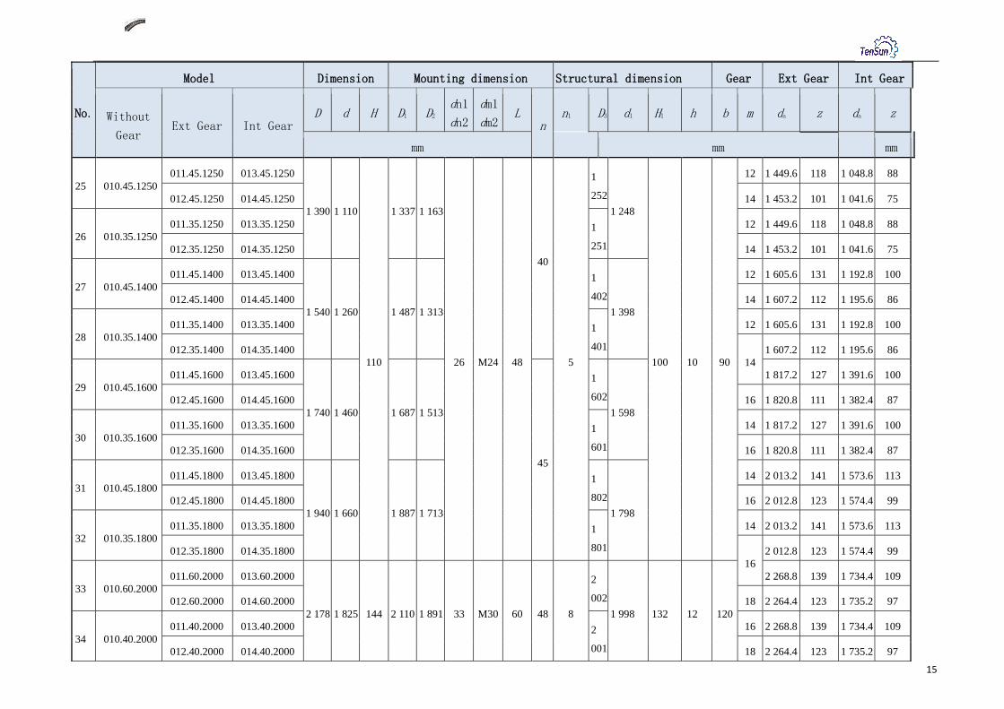
No.
Model Dimension Mounting dimension Structural dimension Gear Ext Gear Int Gear
Without
Gear Ext Gear Int Gear
D d H D1 D2 dn1
dn2
dm1
dm2 L
n n1 D3 d1 H1 h b m da z da z
mm mm mm
25 010.45.1250 011.45.1250 013.45.1250
1 390 1 110
110
1 337 1 163
26 M24 48
40
5
1
252
1 248
100 10 90
12 1 449.6 118 1 048.8 88
012.45.1250 014.45.1250 14 1 453.2 101 1 041.6 75
26 010.35.1250 011.35.1250 013.35.1250 1
251
12 1 449.6 118 1 048.8 88
012.35.1250 014.35.1250 14 1 453.2 101 1 041.6 75
27 010.45.1400 011.45.1400 013.45.1400
1 540 1 260 1 487 1 313
1
402 1 398
12 1 605.6 131 1 192.8 100
012.45.1400 014.45.1400 14 1 607.2 112 1 195.6 86
28 010.35.1400 011.35.1400 013.35.1400 1
401
12 1 605.6 131 1 192.8 100
012.35.1400 014.35.1400 14
1 607.2 112 1 195.6 86
29 010.45.1600 011.45.1600 013.45.1600
1 740 1 460 1 687 1 513
45
1
602
1 598
1 817.2 127 1 391.6 100
012.45.1600 014.45.1600 16 1 820.8 111 1 382.4 87
30 010.35.1600 011.35.1600 013.35.1600 1
601
14 1 817.2 127 1 391.6 100
012.35.1600 014.35.1600 16 1 820.8 111 1 382.4 87
31 010.45.1800 011.45.1800 013.45.1800
1 940 1 660 1 887 1 713
1
802 1 798
14 2 013.2 141 1 573.6 113
012.45.1800 014.45.1800 16 2 012.8 123 1 574.4 99
32 010.35.1800 011.35.1800 013.35.1800 1
801
14 2 013.2 141 1 573.6 113
012.35.1800 014.35.1800 16
2 012.8 123 1 574.4 99
33 010.60.2000 011.60.2000 013.60.2000
2 178 1 825 144 2 110 1 891 33 M30 60 48 8
2
002
1 998 132 12 120
2 268.8 139 1 734.4 109
012.60.2000 014.60.2000 18 2 264.4 123 1 735.2 97
34 010.40.2000 011.40.2000 013.40.2000 2
001
16 2 268.8 139 1 734.4 109
012.40.2000 014.40.2000 18 2 264.4 123 1 735.2 97

16
No.
Model Dimension Mounting dimension Structural dimension Gear Ext Gear Int Gear
Without
Gear Ext Gear Int Gear
D d H D1 D2 dn1
dn2
dm1
dm2 L
n n1 D3 d1 H1 h b m da
z da z
mm mm mm
35 010.60.2240 011.60.2240 013.60.2240
2 418 2 065
144
2 350 2 131
33 M30 60
4
8
8
2 242
2 238
132
12
120
16 2 492.8 153 1 990.4 125
012.60.2240 014.60.2240 18 2 498.4 136 1 987.2 111
36 010.40.2240 011.40.2240 013.40.2240
2 241 16 2 492.8 153 1 990.4 125
012.40.2240 014.40.2240 18
2 498.4 136 1 987.2 111
37 010.60.2500 011.60.2500 013.60.2500
2 678 2 325 2 610 2 391
5
6
2 502
2 498
2 768.4 151 2 239.2 125
012.60.2500 014.60.2500 20 2 776 136 2 228 112
38 010.40.2500 011.40.2500 013.40.2500
2 501 18 2 768.4 151 2 239.2 125
012.40.2500 014.40.2500 20 2 776 136 2 228 112
39 010.60.2800 011.60.2800 013.60.2800
2 978 2 625 2 910 2 691
2 802
2 798
18 3 074.4 168 2 527.2 141
012.60.2800 014.60.2800 20 3 076 151 2 528 127
40 010.40.2800 011.40.2800 013.40.2800
2 801 18 3 074.4 168 2 527.2 141
012.40.2800 014.40.2800 20
3 076 151 2 528 127
41 010.75.3150 011.75.3150 013.75.3150
3 376 2 922
174
3 286 3 014
45 M42 84
3 152
3 147
162 150
3 476 171 2 828 142
012.75.3150 014.75.3150 22 3 471.6 155 2 824.8 129
42 010.50.3150 011.50.3150 013.50.3150
3 148 20 3 476 171 2 828 142
012.50.3150 014.50.3150 22 3 471.6 155 2 824.8 129
43 010.75.3550 011.75.3550 013.75.3550
3 776 3 322 3 686 3 414 3 552
3 547 20 3 876 191 3 228 162
012.75.3550 014.75.3550 22 3 889.6 174 3 220.8 147
44 010.50.3550 011.50.3550 013.50.3550
3 548 20 3 876 191 3 228 162
012.50.3550 014.50.3550 22 3 889.6 174 3 220.8 147

17
No.
Model Dimension Mounting Dimension Structural dimension Gear Ext Gear Int Gear
Without
Gear Ext Gear Int Gear
D d H D1 D2 dn1 dn2
dm1 dm2 L
n n1 D3 d1 H1 h b m da
z da
z
mm mm mm
45 010.75.4000
011.75.4000 013.75.4000
4 226 3 772
174
4 136 3 864
45 M42 84 60 10
4 002
3 997
162 12 150
22 4 329.6 194 3 660.8 167
012.75.4000 014.75.4000 25 4 345 171 3 660 147
46 010.50.4000
011.50.4000 013.50.4000
3 998
22 4 329.6 194 3 660.8 167
012.50.4000 014.50.4000 25 4 345 171 3 660 147
47 010.75.4500
011.75.4500 013.75.4500
4 726 4 272 4 636 4 364 4 502
4 497
22 4 835.6 217 4 166.8 190
012.75.4500 014.75.4500 25 4 845 191 4 160 167
48 010.50.4500
011.50.4500 013.50.4500
4 498
22 4 835.6 217 4 166.8 190
012.50.4500 014.50.4500 25 4 845 191 4 160 167
18
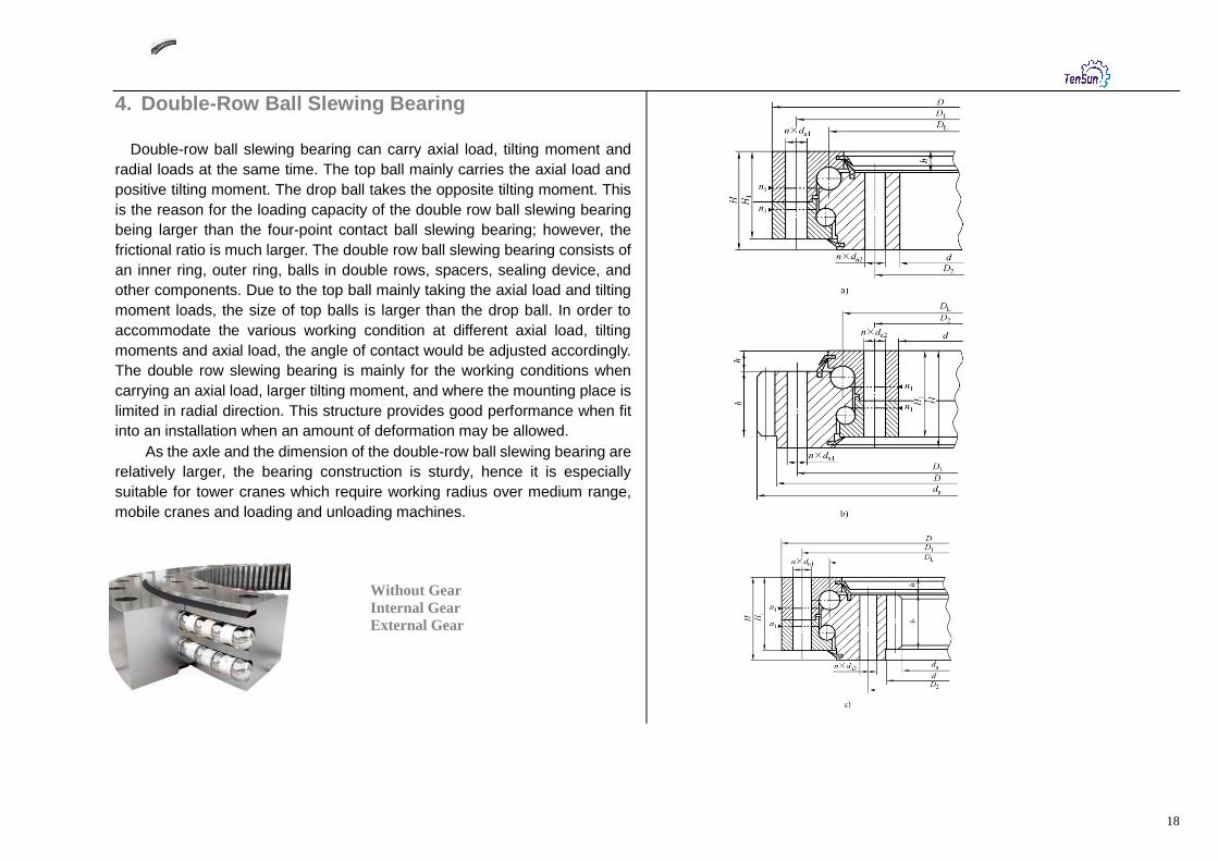
4. Double-Row Ball Slewing Bearing
Double-row ball slewing bearing can carry axial load, tilting moment and
radial loads at the same time. The top ball mainly carries the axial load and
positive tilting moment. The drop ball takes the opposite tilting moment. This
is the reason for the loading capacity of the double row ball slewing bearing
being larger than the four-point contact ball slewing bearing; however, the
frictional ratio is much larger. The double row ball slewing bearing consists of
an inner ring, outer ring, balls in double rows, spacers, sealing device, and
other components. Due to the top ball mainly taking the axial load and tilting
moment loads, the size of top balls is larger than the drop ball. In order to
accommodate the various working condition at different axial load, tilting
moments and axial load, the angle of contact would be adjusted accordingly.
The double row slewing bearing is mainly for the working conditions when
carrying an axial load, larger tilting moment, and where the mounting place is
limited in radial direction. This structure provides good performance when fit
into an installation when an amount of deformation may be allowed.
As the axle and the dimension of the double-row ball slewing bearing are
relatively larger, the bearing construction is sturdy, hence it is especially
suitable for tower cranes which require working radius over medium range,
mobile cranes and loading and unloading machines.
Without Gear
Internal Gear
External Gear

19
No.
Model Dimension Mounting Dimension Structural dimension Gear Ext Gear Int Gear
Without
Gear Ext Gear Int GEAR
D d H D1 D2 dn1 dn2
dm1 dm2
L n n1
H1 h b m da z
da z
mm mm mm
1 020.25.500
021.25.500 023.25.500
616 384
106
580 420
18 M16 32
20
4 96 26 60
5 644 126 357 72
022.25.500 024.25.500 6 646.8 105 350.4 59
2 020.25.560
021.25.560 023.25.560
676 444 640 480
5 704 138 417 84
022.25.560 024.25.560
6
706.8 115 410.4 69
3 020.25.630 021.25.630 023.25.630
746 514 710 550
24
790.8 129 482.4 81
022.25.630 024.25.630 8 790.4 96 475.2 60
4 020.25.710
021.25.710 023.25.710
826 594 790 630
6 862.8 141 560.4 94
022.25.710 024.25.710 8
862.4 105 555.2 70
5 020.30.800 021.30.800 023.30.800
942 658
124
898 702
22 M20 40
30
6 114 29 80
982.4 120 619.2 78
022.30.800 024.30.800 10 988 96 614 62
6 020.30.900
021.30.900 023.30.900
1 042 758 998 802
8 1 086.4 133 715.2 90
022.30.900 024.30.900
10
1 088 106 714 72
7 020.30.1000
021.30.1000 023.30.1000
1 142 858 1 098 902
36
1 198 117 814 82
022.30.1000 024.30.1000 12 1 197.6 97 796.8 67
8 020.30.1120
021.30.1120 023.30.1120
1 262 978 1 218 1 022
10 1 318 129 924 93
022.30.1120 024.30.1120
12
1 317.6 107 916.8 77
9 020.40.1250
021.40.1250 023.40.1250
1 426 1 074
160
1 374 1 126
26 M24 48 40 5 150 39 90
1 497.6 122 1 012.8 85
022.40.1250 024.40.1250 14 1 495.2 104 1 013.6 73
10 020.40.1400
021.40.1400 023.40.1400
1 576 1 224 1 524 1 272
12 1 641.6 134 1 156.8 97
022.40.1400 024.40.1400 14 1 649.2 115 1 153.6 83

20
No.
Model Dimension Mounting Dimension Structural Dimension Gear Ext Gear Int Gear
Without
Gear Ext Gear Int Gear
D d H D1 D2 dn1 dn2
dm1 dm2
L n n1
H1 h b m da z
da z
mm mm mm
11 020.40.1600 021.40.1600 023.40.1600
1 776 1 424
160
1 724 1 476
26 M24 48 45 5 150 39 90
14 1 845.2 129 1 349.6 97
022.40.1600 024.40.1600 16 1 852.8 113 1 350.4 85
12 020.40.1800 021.40.1800 023.40.1800
1 976 1 624 1 924 1 676 14 2 055.2 144 1 545.6 111
022.40.1800 024.40.1800 16
2 060.8 126 1 542.4 97
13 020.50.2000 021.50.2000 023.50.2000
2 215 1 785
190
2 149 1 851
33 M30 60
48
8
178 47 120
2 300.8 141 1 702.4 107
022.50.2000 024.50.2000 18 2 300.4 125 1 699.2 95
14 020.50.2240 021.50.2240 023.50.2240
2 455 2 025 2 389 2 091 16 2 540.8 156 1 942.4 122
022.50.2240 024.50.2240 18
2 552.4 139 1 933.2 108
15 020.50.2500 021.50.2500 023.50.2500
2 715 2 285 2 649 2 351
56
2 804.4 153 2 203.2 123
022.50.2500 024.50.2500 20 2 816 138 2 188 110
16 020.50.2800 021.50.2800 023.50.2800
3 015 2 585 2 949 2 651 18 3 110.4 170 2 491.2 139
022.50.2800 024.50.2800 20
3 116 153 2 488 125
17 020.60.3150 021.60.3150 023.60.3150
3 428 2 872
226
3 338 2 962
45 M42 84 214 56 150
3 536 174 2 768 139
022.60.3150 024.60.3150 22 3 537.6 158 2 758.8 126
18 020.060.3550 021.60.3550 023.60.3550
3 828 3 272 3 738 3 362 20 3 936 194 3 168 159
022.60.3550 024.60.3550 22
3 933.6 176 3 176.8 145
19 020.60.4000 021.60.4000 023.60.4000
4 278 3 722 4 188 3 812
60 10
4 395.6 197 3 618.8 165
022.60.4000 024.60.4000 25 4 395 173 3 610 145
20 020.60.4500 021.60.4500 023.60.4500
4 778 4 222 4 688 4 312 22 4 879.6 219 4 122.8 188
022.60.4500 024.60.4500 25 4 895 193 4 110 165

21
5. Cross Roller Slewing Bearing
The cross roller slewing bearing can carry axial load, tilting moment and
radial load all at the same time. The design and application of the cross
cylindrical roller slewing bearings are basically the same as those of the
four-point contact ball slewing bearing, except that the rolling elements are
substituted from balls into rollers and the contact way between the rolling
elements and rings is changed from point contact into line contact. Those
changes allow for the carrying capacity to be increased, but the wear and the
friction moment load are also increased. As the rollers are 1:1cross arranged,
it is suitable for high precision mounting and capable to bear axial force. The
complement of a full set of rollers is usually taken when the load is heavier.
However, the greater frictional resistance could cause groove marks around
the circle where rollers and raceway contact. This slewing bearing with a
design of a full complement of rollers is mainly applied in the condition where
a heavier axial load is the primary load, and the requirement for tilting
moment and friction moment is not so high.
The single-row crossed roller Slewing Bearings are widely used for
hoisting, transporting, engineering machines as well as for military products.
Without Gear
Internal Gear
External Gear

22
No.
Model Dimension Mounting Dimension Structural Dimension Gear Ext Gear Inn Gear
Without
Gear Ext Gear Int Gear
D d H D1 D2 dn1 dn2
dm1 dm2
L n n1
D3 d1 H1 h b m da z
da z
mm mm mm
1 110.25.500 111.25.500 113.25.500
602 398
75
566 434
18 M16 32
20
4
498 502
65
10
60
5 629 123 367 74
112.25.500 114.25.500 6 628.8 102 368.4 62
2 110.25.560 111.25.560 113.25.560
662 458 626 494 558 562 5 689 135 427 86
112.25.560 114.25.560 6
688.8 112 428.4 72
3 110.25.630 111.25.630 113.25.630
732 528 696 564
24
628 632 772.8 126 494.4 83
112.25.630 114.25.630 8 774.4 94 491.2 62
4 110.25.710 111.25.710 113.25.710
812 608 776 644 708 712 6 850.8 139 572.4 96
112.25.710 114.25.710 8
854.4 104 571.2 72
5 110.28.800 111.28.800 113.28.800
922 678
82
878 722
22 M20 40
30
6
798 802
72 65
966.4 118 635.2 80
112.28.800 114.28.800 10 968 94 634 64
6 110.28.900 111.28.900 113.28.900
1 022 778 978 822 898 902 8 1 062.4 130 739.2 93
112.28.900 114.28.900 10
1 068 104 734 74
7 110.28.1000 111.28.1000 113.28.1000
1 122 878 1 078 922
36
998 1 002 1 188 116 824 83
112.28.1000 114.28.1000 12 1 185.6 96 820.8 69
8 110.25.1120 111.25.1120 113.25.1120
1 242 998 1 198 1 042 1 118 1 122 10 1 298 127 944 95
112.25.1120 114.25.1120 12
1 305.6 106 940.8 79
9 110.32.1250 111.32.1250 113.32.1250
1 390 1 110
91
1 337 1 163
26 M24 48 40 5
1 248 1 252
81 75
1 449.6 118 1 048.8 88
112.32.1250 114.32.1250 14 1 453.2 101 1 041.6 75
10 110.32.1400 111.32.1400 113.32.1400
1 540 1 260 1 487 1 313 1 398 1 402 12 1 605.6 131 1 192.8 100
112.32.1400 114.32.1400 14 1 607.2 112 1 195.6 86

23
No
.
Model Dimension Mounting Gear Structural Dimension Gear Ext Gear Int Gear
Without
Gear Ext Gear Int Gear
D d H D1 D2 dn1 dn2
dm1 dm2
L n n1
D3 d1 H1 h b m da z
da z
mm mm mm
11 110.32.1600 111.32.1600 113.32.1600
1 740 1 460
91
1 687 1 513 26
M24 48 45 5
1 598 1 602
81 10 75
14 1 817.2 127 1 391.6 100
112.32.1600 114.32.1600 16 1 820.8 111 1 382.4 87
12 110.32.1800 111.32.1800 113.32.1800
1 940 1 660 1 887 1 713
33
1 798 1 802 14 2 013.2 141 1 573.6 113
112.32.1800 114.32.1800 16
2 012.8 123 1 574.4 99
13 110.40.2000 111.40.2000 113.40.2000
2 178 1 825
112
2 110 1 891
M30 60
48
8
1 997 2 003
100
12
90
2 268.8 139 1 734.4 109
112.40.2000 114.40.2000 18 2 264.4 123 1 735.2 97
14 110.40.2240 111.40.2240 113.40.2240
2 418 2 065 2 350 2 131 2 237 2 243 16 2 492.8 153 1 990.4 125
112.40.2240 114.40.2240 18
2 498.4 136 1 987.2 111
15 110.40.2500 111.40.2500 113.40.2500
2 678 2 325 2 610 2 391
56
2 497 2 503 2 768.4 151 2 239.2 125
112.40.2500 114.40.2500 20 2 776 136 2 228 112
16 110.40.2800 111.40.2800 113.40.2800
2 978 2 625 2 910 2 691 2 797 2 803 18 3 074.4 168 2 527.2 141
112.40.2800 114.40.2800 20
3 076 151 2 528 127
17 110.50.3150 111.50.3150 113.50.3150
3 376 2 922
134
3 286 3 014
45 M42 84
3 147 3 153
122 110
3 476 171 2 828 142
112.50.3150 114.50.3150 22 3 471.6 155 2 824.8 129
18 110.50.3550 111.50.3550 113.50.3550
3 776 3 322 3 686 3 414 3 547 3 553 20 3 876 191 3 228 162
112.50.3550 114.50.3550 22
3 889.6 174 3 220.8 147
19 110.50.4000 111.50.4000 113.50.4000
4 226 3 772 4 136 3 864
60 10
3 997 4 003 4 329.6 194 3 660.8 167
112.50.4000 114.50.4000 25 4 345 171 3 660 147
20 110.50.4500 111.50.4500 113.50.4500
4 726 4 272 4 636 4 364 4 497 4 503 22 4 835.6 217 4 166.8 190
112.50.4500 114.50.4500 25 4 845 191 4 160 167

24
6. Three-Row Roller Slewing Bearing The three row cylindrical roller combined slewing bearing can carry axial
load, tilting moment, and radial load all at the same time. Compared to
cross-cylindrical roller slewing bearing the load of each roller is reduced.
Point contact is changed into line contact compared with that of a double row
ball slewing bearing, so the contact stresses are also decreased. Therefore,
the load capacity of this design of slewing bearing is the highest under the
conditions of a bearing with the same boundary dimensions.
The three row cylindrical roller combined slewing bearing mainly consists of
the components such as inner ring, outer ring, three rows of rollers, cage
(spacing blocks), a seal device etc. This slewing bearing design is suitable
for most applications where a large axial load and tilting moment, or with a
larger radial load, or with a low requirement for friction moment.
Three row rollers slewing bearing, which is matching with port crane. Due to
has high carrying capacity. It is also widely used in the bucket, overweight
transportation machinery, port machinery, mining machinery, and
construction machinery, park recreation machine, filling machine, missile
launchers and other large rotary device.
Without Gear
Internal Gear
External Gear

25
No.
Model Dimension Mounting Dimension Structural
Dimension Gear Ext Gear Int Gear
Without
Gear Ext Gear Int Gear
D d H D1 D2 dn1 dn2
dm1 dm2
L n n1
H1 h
b m da z da z
mm mm mm
1 130.25.500 131.25.500 133.25.500
634 366
148
598 402
18 M16 32
24
4
138 32
80
5 664 130 337 68
132.25.500 134.25.500 6 664.8 108 338.4 57
2 130.25.560 131.25.560 133.25.560
694 426 658 462 5 724 142 397 80
132.25.560 134.25.560 6
724.8 118 398.4 67
3 130.25.630 131.25.630 133.25.630
764 496 728 532
28
808.8 132 458.4 77
132.25.630 134.25.630 8 806.4 98 459.2 58
4 130.25.710 131.25.710 133.25.710
844 576 808 612 6 886.8 145 536.4 90
132.25.710 134.25.710 8
886.4 108 539.2 68
5 130.32.800 131.32.800 133.32.800
964 636
182
920 680
22 M20 40
36
172 40
120
1 006.4 123 595.2 75
132.32.800 134.32.800 10 1 008 98 594 60
6 130.32.900 131.32.900 133.32.900
1 064 736 1 020 780 8 1 102.4 135 691.2 87
132.32.900 134.32.900 10
1 108 108 694 70
7 130.32.1000 131.32.1000 133.32.1000
1 164 836 1 120 880
40
5
1 218 119 784 79
132.32.1000 134.32.1000 12 1 221.6 99 784.8 66
8 130.32.1120 131.32.1120 133.32.1120
1 284 956 1 240 1 000 10 1 338 131 904 91
132.32.1120 134.32.1120 12
1 341.6 109 904.8 76
9 130.40.1250 131.40.1250 133.40.1250
1 445 1 055
220
1 393 1 107
26 M24 48 45 210 50
150
1 509.6 123 988.8 83
132.40.1250 134.40.1250 14 1 509.2 105 985.6 71
10 130.40.1400 131.40.1400 133.40.1400
1 595 1 205 1 543 1 257 12 1 665.6 136 1 144.8 96
132.40.1400 134.40.1400 14 1 663.2 116 1 139.6 82

26
No.
Model Dimension Mounting Dimension Structural dimension Gear Ext Gear Int Gear
Without
Gear Ext Gear Int Gear
D d H D1 D2 dn1 dn2
dm1 dm2
L n n1
H1 h b m da z
da z
mm mm mm
11 130.40.1600 131.40.1600 133.40.1600
1 795 1 405
220
1 743 1 457
26 M24 48 48
6
210 50 150
14 1 873.2 131 1 335.6 96
132.40.1600 134.40.1600 16 1 868.8 114 1 334.4 84
12 130.40.1800 131.40.1800 133.40.1800
1 995 1 605 1 943 1 657 14 2 069.2 145 1 531.6 110
132.40.1800 134.40.1800 16
2 076.8 127 1 526.4 96
13 130.45.2000 131.45.2000 133.45.2000
2 221 1 779
231
2 155 1 845
33 M30 60
60
219 54 160
2 300.8 141 1 702.4 107
132.45.2000 134.45.2000 18 2 300.4 125 1 699.2 95
14 130.45.2240 131.45.2240 133.45.2240
2 461 2 019 2 395 2 085 16 2 556.8 157 1 926.4 121
132.45.2240 134.45.2240 18
2 552.4 139 1 933.2 108
15 130.45.2500 131.45.2500 133.45.2500
2 721 2 279 2 655 2 345
72
8
2 822.4 154 2 185.2 122
132.45.2500 134.45.2500 20 2 816 138 2 188 110
16 130.45.2800 131.45.2800 133.45.2800
3 021 2 579 2 955 2 645 18 3 110.4 170 2 491.2 139
132.45.2800 134.45.2800 20
3 116 153 2 488 125
17 130.50.3150 131.50.3150 133.50.3150
3 432 2 868
270
3 342 2 958
45 M42 84 258 65 180
3 536 174 2 768 139
132.50.3150 134.50.3150 22 3 537.6 158 2 758.8 126
18 130.50.3550 131.50.3550 133.50.3550
3 832 3 268 3 742 3 358 20 3 936 194 3 168 159
132.50.3550 134.50.3550 22
3 933.6 176 3 154.8 144
19 130.50.4000 131.50.4000 133.50.4000
4 282 3 718 4 192 3 808
80
4 395.6 197 3 616.8 165
132.50.4000 134.50.4000 25 4 395 173 3 610 145
20 130.50.4500 131.50.4500 133.50.4500
4 782 4 218 4 692 4 308 22 4 901.6 220 4 122.8 188
132.50.4500 134.50.4500 25 4 895 193 4 110 165
27
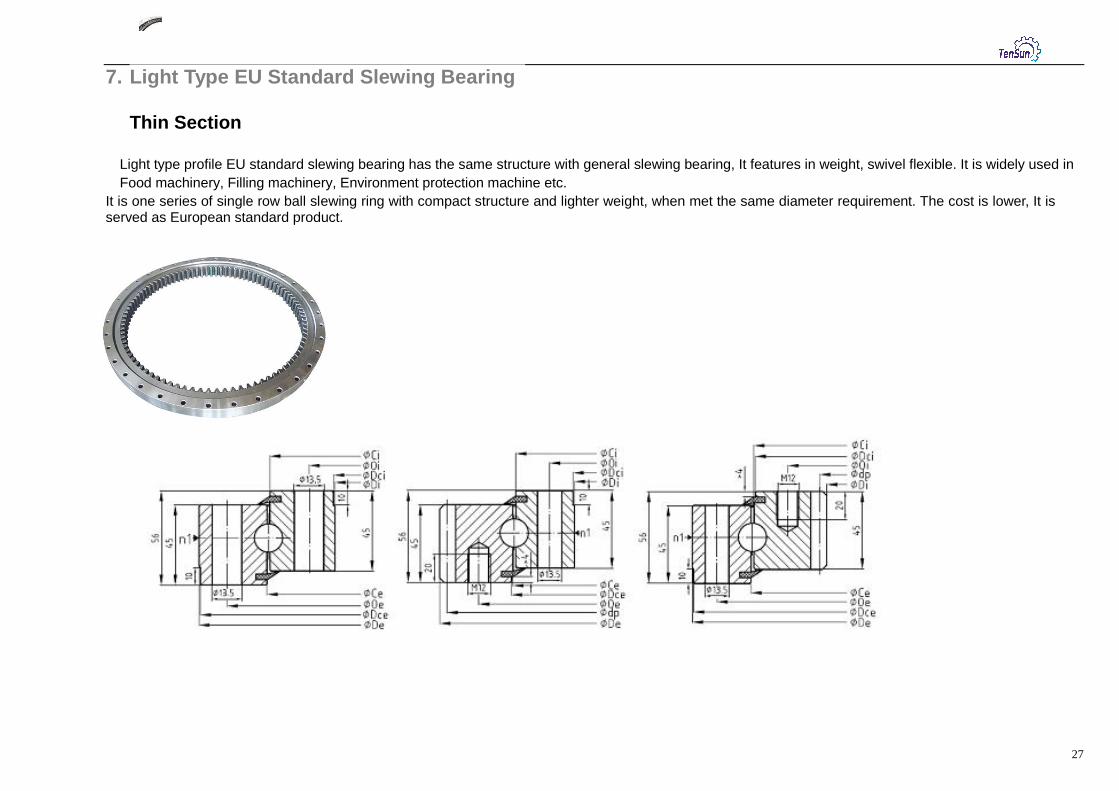
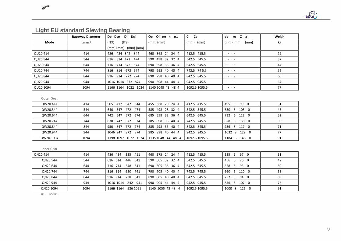
7. Light Type EU Standard Slewing Bearing Thin Section
Light type profile EU standard slewing bearing has the same structure with general slewing bearing, It features in weight, swivel flexible. It is widely used in
Food machinery, Filling machinery, Environment protection machine etc.
It is one series of single row ball slewing ring with compact structure and lighter weight, when met the same diameter requirement. The cost is lower, It is served as European standard product.
28
Light EU standard Slewing Bearing
Mode
Raceway Diameter De Dce Di Dci Oe Oi ne ni n1 Ci Ce dp m Z x Weigh
(mm) (IT9) (IT9) (mm) (mm) (mm) (mm) (mm) (mm) (mm) kg
(mm) (mm) (mm) (mm)
QU20.414 414 486 484 342 344 460 368 24 24 4 412.5 415.5 · · · · 29
QU20.544 544 616 614 472 474 590 498 32 32 4 542.5 545.5 · · · · 37
QU20.644 644 716 714 572 574 690 598 36 36 4 642.5 645.5 · · · · 44
QU20.744 744 816 814 672 674 790 698 40 40 4 742.5 74 5.5 · · · · 52
QU20.844 844 916 914 772 774 890 798 40 40 4 842.5 845.5 · · · · 60
QU20.944 944 1016 1014 872 874 990 898 44 44 4 942.5 945.5 · · · · 67
QU20.1094 1094 1166 1164 1022 1024 1140 1048 48 48 4 1092.5 1095.5 · · · · 77
Outer Gear
QW20.414 414 505 417 342 344 455 368 20 24 4 412.5 415.5 495 5 99 0 31
QW20.544 544 640 547 472 474 585 498 28 32 4 542.5 545.5 630 6 105 0 43
QW20.644 644 742 647 572 574 685 598 32 36 4 642.5 645.5 732 6 122 0 52
QW20.744 744 838 747 672 674 785 698 36 40 4 742.5 745.5 828 6 138 0 59
QW20.844 844 950 847 772 774 885 798 36 40 4 842.5 845.5 936 8 117 0 71
QW20.944 944 1046 947 872 874 985 898 40 44 4 942.5 945.5 1032 8 129 0 77
QW20.1094 1094 1198 1097 1022 1024 1135 1048 44 48 4 1092.5 1095.5 1184 8 148 0 91
Inner Gear
QN20.414 414 486 484 325 411 460 375 24 24 4 412.5 415.5 335 5 67 0 31
QN20.544 544 616 614 446 541 590 505 32 32 4 542.5 545.5 456 6 76 0 42
QN20.644 644 716 714 548 641 690 605 36 36 4 642.5 645.5 558 6 93 0 50
QN20.744 744 816 814 650 741 790 705 40 40 4 742.5 745.5 660 6 110 0 58
QN20.844 844 916 914 738 841 890 805 40 40 4 842.5 845.5 752 8 94 0 69
QN20.944 944 1016 1014 842 941 990 905 44 44 4 942.5 945.5 856 8 107 0 76
QN20.1094 1094 1166 1164 986 1091 1140 1055 48 48 4 1092.5 1095.5 1000 8 125 0 91
n1: M8×1

29
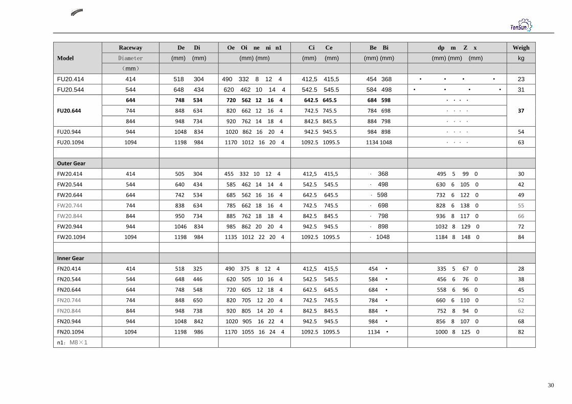
Light Slewing Bearing With Flange
Light type profile slewing bearing has the same structure with general slewing bearing, it features in weight, swivel flexible . It is widely used in food machinery , filling machinery , environment protection machine and so on .
Widely applied on larger diameter and limited heavy machinery, light bearing capacity, More for light machinery like small crane, Manual lift, Turntable ladder and so on.
30
Model
Raceway De Di Oe Oi ne ni n1 Ci Ce Be Bi dp m Z x Weigh
Diameter (mm) (mm) (mm) (mm) (mm) (mm) (mm) (mm) (mm) (mm) (mm) kg
(mm)
FU20.414 414 518 304 490 332 8 12 4 412,5 415,5 454 368 · · · · 23
FU20.544 544 648 434 620 462 10 14 4 542.5 545.5 584 498 · · · · 31
FU20.644
644 748 534 720 562 12 16 4 642.5 645.5 684 598 · · · ·
37 744 848 634 820 662 12 16 4 742.5 745.5 784 698 · · · ·
844 948 734 920 762 14 18 4 842.5 845.5 884 798 · · · ·
FU20.944 944 1048 834 1020 862 16 20 4 942.5 945.5 984 898 · · · · 54
FU20.1094 1094 1198 984 1170 1012 16 20 4 1092.5 1095.5 1134 1048 · · · · 63
Outer Gear
FW20.414 414 505 304 455 332 10 12 4 412,5 415,5 · 368 495 5 99 0 30
FW20.544 544 640 434 585 462 14 14 4 542.5 545.5 · 498 630 6 105 0 42
FW20.644 644 742 534 685 562 16 16 4 642.5 645.5 · 598 732 6 122 0 49
FW20.744 744 838 634 785 662 18 16 4 742.5 745.5 · 698 828 6 138 0 55
FW20.844 844 950 734 885 762 18 18 4 842.5 845.5 · 798 936 8 117 0 66
FW20.944 944 1046 834 985 862 20 20 4 942.5 945.5 · 898 1032 8 129 0 72
FW20.1094 1094 1198 984 1135 1012 22 20 4 1092.5 1095.5 · 1048 1184 8 148 0 84
Inner Gear
FN20.414 414 518 325 490 375 8 12 4 412,5 415,5 454 · 335 5 67 0 28
FN20.544 544 648 446 620 505 10 16 4 542.5 545.5 584 · 456 6 76 0 38
FN20.644 644 748 548 720 605 12 18 4 642.5 645.5 684 · 558 6 96 0 45
FN20.744 744 848 650 820 705 12 20 4 742.5 745.5 784 · 660 6 110 0 52
FN20.844 844 948 738 920 805 14 20 4 842.5 845.5 884 · 752 8 94 0 62
FN20.944 944 1048 842 1020 905 16 22 4 942.5 945.5 984 · 856 8 107 0 68
FN20.1094 1094 1198 986 1170 1055 16 24 4 1092.5 1095.5 1134 · 1000 8 125 0 82
n1:M8×1

31