
SLB Administration Guide - Oracle · SLB technology enables a switch to distribute input traffic to...
72
Sun Ethernet Fabric Operating System SLB Administration Guide Part No.: E26351-03 July 2013
Transcript of SLB Administration Guide - Oracle · SLB technology enables a switch to distribute input traffic to...
Sun Ethernet Fabric Operating System
SLB Administration Guide
Part No.: E26351-03July 2013

Copyright © 2010, 2013, Oracle and/or its affiliates. All rights reserved.This software and related documentation are provided under a license agreement containing restrictions on use and disclosure and are protected byintellectual property laws. Except as expressly permitted in your license agreement or allowed by law, you may not use, copy, reproduce, translate,broadcast, modify, license, transmit, distribute, exhibit, perform, publish, or display any part, in any form, or by any means. Reverse engineering,disassembly, or decompilation of this software, unless required by law for interoperability, is prohibited.The information contained herein is subject to change without notice and is not warranted to be error-free. If you find any errors, please report them to usin writing.If this is software or related software documentation that is delivered to the U.S. Government or anyone licensing it on behalf of the U.S. Government, thefollowing notice is applicable:U.S. GOVERNMENT END USERS. Oracle programs, including any operating system, integrated software, any programs installed on the hardware,and/or documentation, delivered to U.S. Government end users are "commercial computer software" pursuant to the applicable Federal AcquisitionRegulation and agency-specific supplemental regulations. As such, use, duplication, disclosure, modification, and adaptation of the programs, includingany operating system, integrated software, any programs installed on the hardware, and/or documentation, shall be subject to license terms and licenserestrictions applicable to the programs. No other rights are granted to the U.S. Government.This software or hardware is developed for general use in a variety of information management applications. It is not developed or intended for use in anyinherently dangerous applications, including applications that may create a risk of personal injury. If you use this software or hardware in dangerousapplications, then you shall be responsible to take all appropriate fail-safe, backup, redundancy, and other measures to ensure its safe use. OracleCorporation and its affiliates disclaim any liability for any damages caused by use of this software or hardware in dangerous applications.Oracle and Java are registered trademarks of Oracle and/or its affiliates. Other names may be trademarks of their respective owners.Intel and Intel Xeon are trademarks or registered trademarks of Intel Corporation. All SPARC trademarks are used under license and are trademarks orregistered trademarks of SPARC International, Inc. AMD, Opteron, the AMD logo, and the AMD Opteron logo are trademarks or registered trademarks ofAdvanced Micro Devices. UNIX is a registered trademark of The Open Group.This software or hardware and documentation may provide access to or information on content, products, and services from third parties. OracleCorporation and its affiliates are not responsible for and expressly disclaim all warranties of any kind with respect to third-party content, products, andservices. Oracle Corporation and its affiliates will not be responsible for any loss, costs, or damages incurred due to your access to or use of third-partycontent, products, or services.
Copyright © 2010, 2013, Oracle et/ou ses affiliés. Tous droits réservés.Ce logiciel et la documentation qui l’accompagne sont protégés par les lois sur la propriété intellectuelle. Ils sont concédés sous licence et soumis à desrestrictions d’utilisation et de divulgation. Sauf disposition de votre contrat de licence ou de la loi, vous ne pouvez pas copier, reproduire, traduire,diffuser, modifier, breveter, transmettre, distribuer, exposer, exécuter, publier ou afficher le logiciel, même partiellement, sous quelque forme et parquelque procédé que ce soit. Par ailleurs, il est interdit de procéder à toute ingénierie inverse du logiciel, de le désassembler ou de le décompiler, excepté àdes fins d’interopérabilité avec des logiciels tiers ou tel que prescrit par la loi.Les informations fournies dans ce document sont susceptibles de modification sans préavis. Par ailleurs, Oracle Corporation ne garantit pas qu’ellessoient exemptes d’erreurs et vous invite, le cas échéant, à lui en faire part par écrit.Si ce logiciel, ou la documentation qui l’accompagne, est concédé sous licence au Gouvernement des Etats-Unis, ou à toute entité qui délivre la licence dece logiciel ou l’utilise pour le compte du Gouvernement des Etats-Unis, la notice suivante s’applique :U.S. GOVERNMENT END USERS. Oracle programs, including any operating system, integrated software, any programs installed on the hardware,and/or documentation, delivered to U.S. Government end users are "commercial computer software" pursuant to the applicable Federal AcquisitionRegulation and agency-specific supplemental regulations. As such, use, duplication, disclosure, modification, and adaptation of the programs, includingany operating system, integrated software, any programs installed on the hardware, and/or documentation, shall be subject to license terms and licenserestrictions applicable to the programs. No other rights are granted to the U.S. Government.Ce logiciel ou matériel a été développé pour un usage général dans le cadre d’applications de gestion des informations. Ce logiciel ou matériel n’est pasconçu ni n’est destiné à être utilisé dans des applications à risque, notamment dans des applications pouvant causer des dommages corporels. Si vousutilisez ce logiciel ou matériel dans le cadre d’applications dangereuses, il est de votre responsabilité de prendre toutes les mesures de secours, desauvegarde, de redondance et autres mesures nécessaires à son utilisation dans des conditions optimales de sécurité. Oracle Corporation et ses affiliésdéclinent toute responsabilité quant aux dommages causés par l’utilisation de ce logiciel ou matériel pour ce type d’applications.Oracle et Java sont des marques déposées d’Oracle Corporation et/ou de ses affiliés.Tout autre nom mentionné peut correspondre à des marquesappartenant à d’autres propriétaires qu’Oracle.Intel et Intel Xeon sont des marques ou des marques déposées d’Intel Corporation. Toutes les marques SPARC sont utilisées sous licence et sont desmarques ou des marques déposées de SPARC International, Inc. AMD, Opteron, le logo AMD et le logo AMD Opteron sont des marques ou des marquesdéposées d’Advanced Micro Devices. UNIX est une marque déposée d’The Open Group.Ce logiciel ou matériel et la documentation qui l’accompagne peuvent fournir des informations ou des liens donnant accès à des contenus, des produits etdes services émanant de tiers. Oracle Corporation et ses affiliés déclinent toute responsabilité ou garantie expresse quant aux contenus, produits ouservices émanant de tiers. En aucun cas, Oracle Corporation et ses affiliés ne sauraient être tenus pour responsables des pertes subies, des coûtsoccasionnés ou des dommages causés par l’accès à des contenus, produits ou services tiers, ou à leur utilisation.
PleaseRecycle
Contents
Using This Documentation 1
Product Notes 1
Related Documentation 2
Acronyms and Abbreviations 2
CLI Command Modes 3
Feedback 4
Support and Accessibility 4
SLB Overview 5
Configuring the SLB Topology Example 5
SLB Description 5
SLB Topology Example 6
SLB Configuration Guidelines and Prerequisites 6
Valid Configuration Example 7
Invalid Configuration Examples 7
Default Settings 7
Configuring the SLB-L2 Topology Example 7
SLB-L2 Description 8
SLB-L2 Topology Example 8
SLB-L2 Configuration Guidelines and Prerequisites 9
Default Settings 9
Conditions for a Member Participating in Load Distribution 9
iii

Configuring SLB Entries 11
▼ Create SLB Server Members 11
▼ Remove SLB Server Members 12
▼ Set the Traffic Distribution Policy 13
▼ Restore the Default Traffic Distribution Policy 13
▼ Create Multiple LBGs 14
▼ Set the ICMP Parameters 14
▼ Set the Health-Monitor Parameters 14
Server Health-Check Function 14
Configuring SLB-L2 Entries 17
▼ Create SLB-L2 Server Members 17
▼ Remove SLB-L2 Port Members 18
▼ View the Traffic Distribution Policy 19
▼ Restore the Default Traffic Distribution Policy 19
▼ Set the Failover Method 19
▼ Restore the Default Failover Method 20
▼ Create Multiple SLB-L2 Groups 20
Creating Example SLB Configurations 21
Creating a Basic SLB Configuration 21
Basic SLB Configuration 22
Basic SLB Configuration Steps 22
▼ Set Up the Switch (Basic SLB) 23
▼ Set Up the Client (Basic SLB) 24
▼ Set Up the Server (Basic SLB) 25
▼ Enable the Switch Ports (Basic SLB) 25
▼ Save the Current Configuration (Basic SLB) 26
Creating a Separate VLAN SLB Configuration 26
iv Sun Ethernet Fabric Operating System SLB Administration Guide • July 2013

Separate VLAN SLB Configuration 27
Configuration With Separate VLANs Steps 28
▼ Set Up the Switch (Separate VLAN SLB) 28
▼ Set Up the Client (Separate VLAN SLB) 30
▼ Set Up the Server (Separate VLAN SLB) 31
▼ Enable the Switch Ports (Separate VLAN SLB) 31
▼ Save the Current Configuration (Separate VLAN SLB) 33
Creating a Multiple SLB Group Configuration 33
Multiple-SLB-Group Configuration 33
Configuration With Multiple SLB Groups Steps 35
▼ Set Up Switch A 36
▼ Set Up Switch B 39
▼ Set Up the Client (Multiple SLB Group) 40
▼ Set Up the Servers in SLB Group 1 41
▼ Set Up the Servers in SLB Group 2 41
▼ Enable the Switch Ports (Multiple SLB Group) 42
▼ Save the Current Configuration (Multiple SLB Group) 45
Creating a Failover Example 45
Failover Example 45
▼ Trigger a Failover 46
▼ Restart the Server Following Failure 46
Creating SLB-L2 Configuration Examples 49
Bump-In-The-Wire Configuration 49
Creating a Single-Switch Configuration 49
Basic Single-Switch Configuration 50
▼ Create a Single-Switch Configuration 50
Creating a Dual-Switch Configuration 56
Dual-Switch Configuration 56
Contents v
▼ Create a Dual-Switch Configuration 57
Creating an SLB-L2 Failover Example 63
SLB-L2 Failover Example 63
▼ Trigger a Failover 63
▼ Restart the Interface Following Failure 64
vi Sun Ethernet Fabric Operating System SLB Administration Guide • July 2013
Using This Documentation
Oracle’s SEFOS SLB provides traffic load distribution functions on the switch. Withthis feature, traffic entering the switch can be distributed to switch-connected serversas determined by a specific hash traffic distribution policy.
■ “Product Notes” on page 1
■ “Related Documentation” on page 2
■ “Acronyms and Abbreviations” on page 2
■ “CLI Command Modes” on page 3
■ “Feedback” on page 4
■ “Support and Accessibility” on page 4
Product NotesFor late-breaking information and known issues about the following products, referto the product notes at:
Oracle Switch ES1-24:
http://www.oracle.com/goto/ES1-24/docs
Sun Network 10GbE Switch 72p:
http://www.oracle.com/goto/SN-10GbE-72p/docs
Sun Blade 6000 Ethernet Switched NEM 24p 10GbE:
http://www.oracle.com/goto/SB6K-24p-10GbE/docs
1
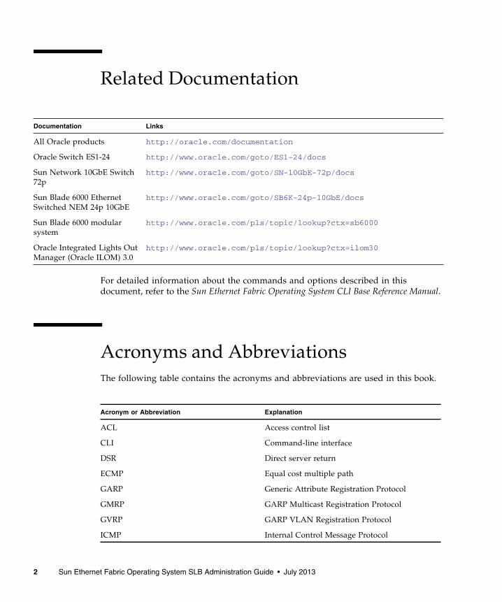
Related Documentation
For detailed information about the commands and options described in thisdocument, refer to the Sun Ethernet Fabric Operating System CLI Base Reference Manual.
Acronyms and AbbreviationsThe following table contains the acronyms and abbreviations are used in this book.
Documentation Links
All Oracle products http://oracle.com/documentation
Oracle Switch ES1-24 http://www.oracle.com/goto/ES1-24/docs
Sun Network 10GbE Switch72p
http://www.oracle.com/goto/SN-10GbE-72p/docs
Sun Blade 6000 EthernetSwitched NEM 24p 10GbE
http://www.oracle.com/goto/SB6K-24p-10GbE/docs
Sun Blade 6000 modularsystem
http://www.oracle.com/pls/topic/lookup?ctx=sb6000
Oracle Integrated Lights OutManager (Oracle ILOM) 3.0
http://www.oracle.com/pls/topic/lookup?ctx=ilom30
Acronym or Abbreviation Explanation
ACL Access control list
CLI Command-line interface
DSR Direct server return
ECMP Equal cost multiple path
GARP Generic Attribute Registration Protocol
GMRP GARP Multicast Registration Protocol
GVRP GARP VLAN Registration Protocol
ICMP Internal Control Message Protocol
2 Sun Ethernet Fabric Operating System SLB Administration Guide • July 2013
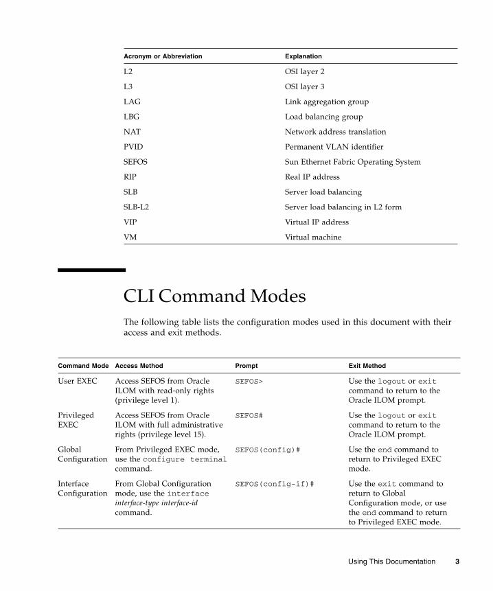
CLI Command ModesThe following table lists the configuration modes used in this document with theiraccess and exit methods.
L2 OSI layer 2
L3 OSI layer 3
LAG Link aggregation group
LBG Load balancing group
NAT Network address translation
PVID Permanent VLAN identifier
SEFOS Sun Ethernet Fabric Operating System
RIP Real IP address
SLB Server load balancing
SLB-L2 Server load balancing in L2 form
VIP Virtual IP address
VM Virtual machine
Command Mode Access Method Prompt Exit Method
User EXEC Access SEFOS from OracleILOM with read-only rights(privilege level 1).
SEFOS> Use the logout or exitcommand to return to theOracle ILOM prompt.
PrivilegedEXEC
Access SEFOS from OracleILOM with full administrativerights (privilege level 15).
SEFOS# Use the logout or exitcommand to return to theOracle ILOM prompt.
GlobalConfiguration
From Privileged EXEC mode,use the configure terminalcommand.
SEFOS(config)# Use the end command toreturn to Privileged EXECmode.
InterfaceConfiguration
From Global Configurationmode, use the interfaceinterface-type interface-idcommand.
SEFOS(config-if)# Use the exit command toreturn to GlobalConfiguration mode, or usethe end command to returnto Privileged EXEC mode.
Acronym or Abbreviation Explanation
Using This Documentation 3

FeedbackProvide feedback on this documentation at:
http://www.oracle.com/goto/docfeedback
Support and AccessibilityOracle customers have access to electronic support through My Oracle Support. Forinformation visit http://www.oracle.com/pls/topic/lookup?ctx=acc&id=info or visit http://www.oracle.com/pls/topic/lookup?ctx=acc&id=trsif you are hearing impaired.
4 Sun Ethernet Fabric Operating System SLB Administration Guide • July 2013
SLB Overview
SLB technology enables a switch to distribute input traffic to switch connectedservers. SLB operates in two different forms, SLB (traffic distribution to target serversthrough L3 routing) and SLB-L2 (traffic distribution to switch port-connected serversthrough L2 switching).
These sections describe these two forms of SLB and show examples of some commonconfigurations.
■ “Configuring the SLB Topology Example” on page 5
■ “Configuring the SLB-L2 Topology Example” on page 7
■ “Conditions for a Member Participating in Load Distribution” on page 9
Configuring the SLB Topology ExampleThese sections describes how to configure the example.
■ “SLB Description” on page 5
■ “SLB Topology Example” on page 6
■ “SLB Configuration Guidelines and Prerequisites” on page 6
■ “Default Settings” on page 7
SLB DescriptionIn SLB, LBGs include server members identified by level-3 protocol (IP) addresses.Server members can be physical servers (server blades or rackmounted servers) orVMs with IP addresses assigned. Technically, server members in an LBG are multiplenext hops of an ECMP route. Each LBG is identified by a VIP address that is used torepresent the IP address of the virtual server. From the client network, the virtualserver is highly available with dynamically reconfigurable resources. Loaddistribution is performed using the routing hash function of the switch. Loaddistribution policies are based on the contents of the L3/4 packet header. Failover is
5

supported at the server member’s level. A failed member within an LBG is replacedby another server member residing within the same LBG. A health check isperformed by the switch using an ICMP ping.
SLB Topology Example
When traffic that arrives from the client to the server needs to be distributed to thevirtual server (traffic with destination IP address as VIP), ECMP routing occurs. Thedestination MAC address of each packet is changed to the MAC address of the realserver by the switch hardware in wire speed. In return traffic (from the server to theclient), DSR is used to directly forward to the client all traffic returning to the clients.No ECMP routing occurs in backward traffic. The real server returns the packet withthe source IP address set to the VIP instead of its own IP address, which is madepossible by setting the loopback interface (for example, lo0) in each serverparticipating in the LBG. The loopback interface provides address aliasing for theVIP, but will not respond to ARP requests of the VIP. No NAT is involved in eitherthe forward and reverse direction.
SLB Configuration Guidelines and PrerequisitesThese guidelines and prerequisites apply to SLB configurations:
■ Set up as many as 16 servers per SLB group.
■ Establish up to 16 SLB groups.
■ Set up as many as 32 servers on the switch for load balancing.
■ Ensure that server members within an SLB group do not span multiple VLANs.
■ Choose any IP address for a VIP, ensuring that the IP address is not in the samesubnet as the physical server’s subnet.
6 Sun Ethernet Fabric Operating System SLB Administration Guide • July 2013
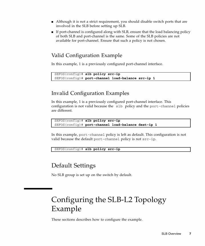
■ Although it is not a strict requirement, you should disable switch ports that areinvolved in the SLB before setting up SLB.
■ If port-channel is configured along with SLB, ensure that the load balancing policyof both SLB and port-channel is the same. Some of the SLB policies are notavailable for port-channel. Ensure that such a policy is not chosen.
Valid Configuration ExampleIn this example, 1 is a previously configured port-channel interface.
Invalid Configuration ExamplesIn this example, 1 is a previously configured port-channel interface. Thisconfiguration is not valid because the slb policy and the port-channel policiesare different.
In this example, port-channel policy is left as default. This configuration is notvalid because the default port-channel policy is not src-ip.
Default SettingsNo SLB group is set up on the switch by default.
Configuring the SLB-L2 TopologyExampleThese sections describes how to configure the example.
SEFOS(config)# slb policy src-ipSEFOS(config)# port-channel load-balance src-ip 1
SEFOS(config)# slb policy src-ipSEFOS(config)# port-channel load-balance dest-ip 1
SEFOS(config)# slb policy src-ip
SLB Overview 7
■ “SLB-L2 Description” on page 8
■ “SLB-L2 Topology Example” on page 8
■ “SLB-L2 Configuration Guidelines and Prerequisites” on page 9
■ “Default Settings” on page 9
SLB-L2 DescriptionIn SLB-L2, an LBG consists of switch port members. Load distribution is performedthrough the LAG hash function of the switch. Load distribution policies are based onthe contents of the L2/3/4 packet header. Failover is supported at the level of theswitch port members. Depending on the fail-over method chosen, a failed memberwithin an LBG is replaced by another switch port or by a group of switch portswithin the LBG. Link-level connectivity between the switch port and the server ismonitored by a health check mechanism.
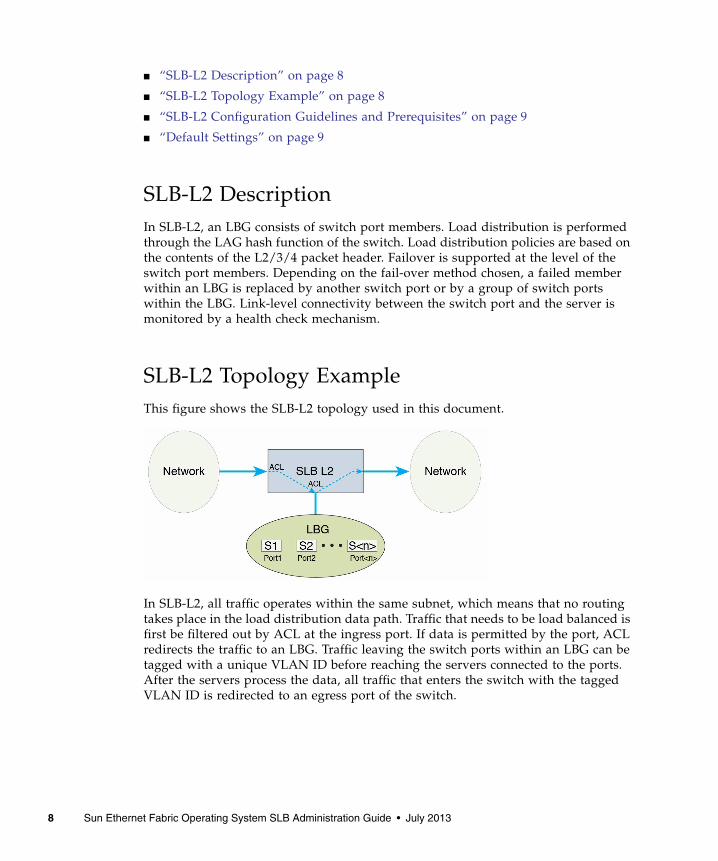
SLB-L2 Topology ExampleThis figure shows the SLB-L2 topology used in this document.
In SLB-L2, all traffic operates within the same subnet, which means that no routingtakes place in the load distribution data path. Traffic that needs to be load balanced isfirst be filtered out by ACL at the ingress port. If data is permitted by the port, ACLredirects the traffic to an LBG. Traffic leaving the switch ports within an LBG can betagged with a unique VLAN ID before reaching the servers connected to the ports.After the servers process the data, all traffic that enters the switch with the taggedVLAN ID is redirected to an egress port of the switch.
8 Sun Ethernet Fabric Operating System SLB Administration Guide • July 2013

You can configure ingress and egress ports as the same or as different ports, referredto as a bump-in-the-wire configuration, where the servers are the "bumps" in the wirefor packet processing. SLB-L2 divides ingress traffic into multiple flows and hashesthem into multiple server members. This mechanism enables simultaneousprocessing of multiple data flows, increasing the overall throughput of the wire.
SLB-L2 Configuration Guidelines andPrerequisitesThese guidelines and prerequisites apply to SLB-L2 configurations:
■ Set up as many as 16 servers per SLB group.
■ Establish up to two SLB groups.
■ For bump-in-the-wire configurations, you must directly connect servers to switchports within an SLB-L2 group.
■ Ensure that SLB and SLB-L2 switch ports do not overlap.
■ Set up only one traffic distribution hash policy on a switch. If the applicationrequires running SLB and SLB-L2 at the same time, the policy must be chosencarefully to work with both SLB and SLB-L2. In such configurations, you must usethe slb l2 policy command to set up a policy that works with both SLB andSLB-L2. When L2 fields are in the hash policy (for example, src-mac, dest-mac,type, vlan-id, vlan-pri, or l2-sym), they will only be recognized by SLB-L2.SLB ignores these L2 fields settings.
Default SettingsNo SLB-L2 group is set up on the switch by default.
Conditions for a Member Participating inLoad DistributionWhen a server member is in an active state, the switch can access the server. Anactive status does not necessarily mean that the server member participates as atarget in the load distribution. Whether the server member actually participates inthe load distribution depends on various factors, including whether the followingconditions are met:
SLB Overview 9

■ The client network to the switch is set up properly.
■ The network interfaces in the clients are up.
■ Each client has a proper route entry for the VIP.
■ Each server has a proper loopback interface (for example, lo0:1) entry for theVIP.
If all of these conditions are satisfied, client traffic will be distributed to the activeservers. Which active servers receive the traffic depends on the traffic distributionhash policy used.
If a server member is shown to be inan idle state, the server member is not reachablefrom the switch. In this case, ensure that the server network to the switch is properlyset up and that the network interface in the server is up.
10 Sun Ethernet Fabric Operating System SLB Administration Guide • July 2013

Configuring SLB Entries
These sections describe how to configure SLB entries using the configurationspresented in “SLB Topology Example” on page 6. These examples were produced ona system running the Oracle Solaris OS.
Before configuring SLB, ensure that the “SLB Configuration Guidelines andPrerequisites” on page 6 are satisfied.
■ “Create SLB Server Members” on page 11
■ “Remove SLB Server Members” on page 12
■ “Set the Traffic Distribution Policy” on page 13
■ “Restore the Default Traffic Distribution Policy” on page 13
■ “Create Multiple LBGs” on page 14
■ “Set the ICMP Parameters” on page 14
■ “Set the Health-Monitor Parameters” on page 14
■ “Server Health-Check Function” on page 14
▼ Create SLB Server MembersWhen you add a server member as the first member of the group, an LBG is created.This example shows adding two server entries, as well as a single standby server, toan LBG.
1. Add the first and second server members.
SEFOS# configure terminalSEFOS(config)# slb 10.10.10.0 255.255.255.0 192.0.0.1,192.0.0.2
11

2. Create a standby SLB server member.
3. Show current LBGs and members.
The following example shows LBG with one active SLB server member and onestandby SLB server member. For information about the status of a server member,see “Conditions for a Member Participating in Load Distribution” on page 9.
▼ Remove SLB Server MembersThis example shows removing one server member from an LBG. You use the sameprocess to remove an active or standby server member.
1. Remove the server entry.
2. Show current LBGs and members.
The following example shows the removal of one of the active SLB servermembers.
SEFOS# configure terminalSEFOS(config)# slb standby 10.10.10.0 255.255.255.0 192.0.0.3SEFOS(config)# end
SEFOS# show slb
SLB Group ID: 1 Virtual IP: 10.10.10.0/24Server Members:IP Address Vlan MacAddress Port State Comments================ ==== ================= ==== ========= ==================192.0.0.1 1 00:14:4f:3e:e0:10 3 ACTIVE192.0.0.2 1 00:14:4f:3e:e0:15 8 IDLE192.0.0.3 1 00:14:4f:3e:e0:19 12 STANDBY (up)
SEFOS# configure terminalSEFOS(config)# no slb standby 10.10.10.0 255.255.255.0 192.0.0.2SEFOS(config)# end
SEFOS# show slb
SLB Group ID: 1 Virtual IP: 10.10.10.0/24Server Members:
12 Sun Ethernet Fabric Operating System SLB Administration Guide • July 2013

▼ Set the Traffic Distribution PolicyThis example shows setting the hash traffic distribution policy to use the source IPaddress for hashing.
1. Set the distribution policy.
2. Show the current traffic distribution policy.
▼ Restore the Default Traffic DistributionPolicy● Type.
IP Address Vlan MacAddress Port State Comments================ ==== ================= ==== ========= ==================192.0.0.1 1 00:14:4f:3e:e0:10 3 ACTIVE192.0.0.3 1 00:14:4f:3e:e0:19 12 STANDBY (up)
SEFOS# configure terminalSEFOS(config)# slb policy src-ipSEFOS(config)# end
SEFOS# show slb policy
L3/4 Hash Fields: src-ipRotation: 0DiffservMask: 0x0UserMask: 0x0FlowLabelMask: 0x0
SEFOS# configure terminalSEFOS(config)# slb policy defaultSEFOS(config)# end
Configuring SLB Entries 13

▼ Create Multiple LBGsTo create more than one LBG, you can execute the slb command as shown inprevious sections, with a different VIP or VIP address mask. This example forms twoLBGs, each with two server members.
● Type.
▼ Set the ICMP Parameters● Type.
▼ Set the Health-Monitor Parameters● Type.
Server Health-Check FunctionThe health-check function is disabled on the switch by default. The function isautomatically enabled when the first server member is added to the first SLB groupon the switch, and it is disabled automatically when the last member is removedfrom the last SLB group on the switch.
SEFOS# configure terminalSEFOS(config)# slb 10.10.10.0 255.255.255.0 192.0.0.1,192.0.0.2SEFOS(config)# slb 10.10.11.0 255.255.255.0 192.0.0.3,192.0.0.4SEFOS(config)# end
SEFOS(config)# slb ping-config default
SEFOS(config)# slb monitor-config default
14 Sun Ethernet Fabric Operating System SLB Administration Guide • July 2013
Each SLB server member in an LBG is monitored by an ICMP ping originated fromthe switch. When ping fails, a failover event takes place. SLB supports anactive-standby configuration. A standby server must be created in order for failoverto take place. When a failure occurs in any of the active servers in the LBG, SLB looksfor the first available standby server within the same SLB group to replace it. When areplacement server is found, all traffic hashed to the failed server will be redirectedto the standby server. Traffic hashed to all other servers is not affected.
Configuring SLB Entries 15

16 Sun Ethernet Fabric Operating System SLB Administration Guide • July 2013

Configuring SLB-L2 Entries
These sections describe how to configure SLB-L2 entries using the sampleconfigurations presented in “SLB Overview” on page 5. Before configuring SLB-L2entries, ensure that you have satisfied the “SLB-L2 Configuration Guidelines andPrerequisites” on page 9.
The server and client setup examples are produced on a system running the OracleSolaris OS.
■ “Create SLB-L2 Server Members” on page 17
■ “Remove SLB-L2 Port Members” on page 18
■ “View the Traffic Distribution Policy” on page 19
■ “Restore the Default Traffic Distribution Policy” on page 19
■ “Set the Failover Method” on page 19
■ “Restore the Default Failover Method” on page 20
■ “Create Multiple SLB-L2 Groups” on page 20
▼ Create SLB-L2 Server MembersWhen you add a member as the first member of a group, an SLB-L2 group is created.The following example shows adding active port members to an SLB-L2 group.
1. Add the first active port member to the group.
SEFOS# configure terminalSEFOS(config)# slb l2 1 extreme-ethernet 0/3-5SEFOS(config)# end
17
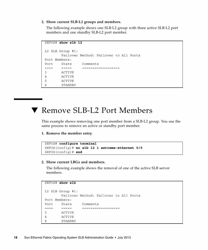
2. Show current SLB-L2 groups and members.
The following example shows one SLB-L2 group with three active SLB-L2 portmembers and one standby SLB-L2 port member.
▼ Remove SLB-L2 Port MembersThis example shows removing one port member from a SLB-L2 group. You use thesame process to remove an active or standby port member.
1. Remove the member entry.
2. Show current LBGs and members.
The following example shows the removal of one of the active SLB servermembers.
SEFOS# show slb l2
L2 SLB Group #1: Failover Method: Failover to All PortsPort Members:Port State Comments==== ===== ==================3 ACTIVE4 ACTIVE5 ACTIVE6 STANDBY
SEFOS# configure terminalSEFOS(config)# no slb l2 1 extreme-ethernet 0/5SEFOS(config)# end
SEFOS# show slb
L2 SLB Group #1: Failover Method: Failover to All PortsPort Members:Port State Comments==== ===== ==================3 ACTIVE4 ACTIVE6 STANDBY
18 Sun Ethernet Fabric Operating System SLB Administration Guide • July 2013

▼ View the Traffic Distribution Policy● Type.
▼ Restore the Default Traffic DistributionPolicy● Type.
▼ Set the Failover Method● Type.
SEFOS# show slb l2 policy
L2 Hash Fields:L3/4 Hash Fields: src-ipRotation: 0DiffservMask: 0x0UserMask: 0x0FlowLabelMask: 0x0
SEFOS# configure terminalSEFOS(config)# slb l2 policy defaultSEFOS(config)# end
SEFOS# configure terminalSEFOS(config)# slb l2 failover-method 1 standbySEFOS(config)# end
Configuring SLB-L2 Entries 19
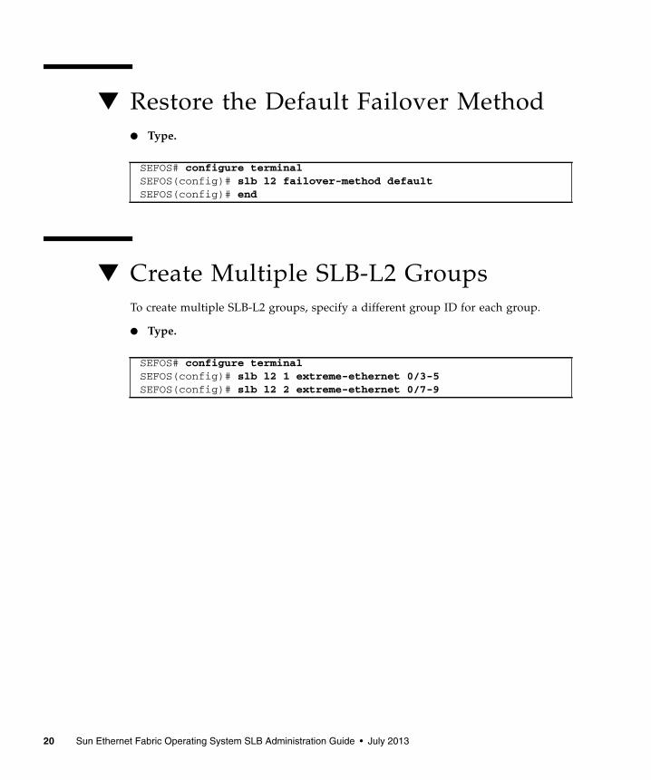
▼ Restore the Default Failover Method● Type.
▼ Create Multiple SLB-L2 GroupsTo create multiple SLB-L2 groups, specify a different group ID for each group.
● Type.
SEFOS# configure terminalSEFOS(config)# slb l2 failover-method defaultSEFOS(config)# end
SEFOS# configure terminalSEFOS(config)# slb l2 1 extreme-ethernet 0/3-5SEFOS(config)# slb l2 2 extreme-ethernet 0/7-9
20 Sun Ethernet Fabric Operating System SLB Administration Guide • July 2013

Creating Example SLBConfigurations
There are many ways you can configure SLB. The following examples show somecommon usage cases. All host command lines are shown in the Oracle Solaris OS.
The following sections provide examples for a basic SLB configuration, aconfiguration with separate VLANs, and a configuration with multiple SLB groups.
■ “Creating a Basic SLB Configuration” on page 21
■ “Creating a Separate VLAN SLB Configuration” on page 26
■ “Creating a Multiple SLB Group Configuration” on page 33
■ “Creating a Failover Example” on page 45
Creating a Basic SLB ConfigurationThese sections describe how to create a basic SLB configuration.
■ “Basic SLB Configuration” on page 22
■ “Basic SLB Configuration Steps” on page 22
■ “Set Up the Switch (Basic SLB)” on page 23
■ “Set Up the Client (Basic SLB)” on page 24
■ “Set Up the Server (Basic SLB)” on page 25
■ “Enable the Switch Ports (Basic SLB)” on page 25
■ “Save the Current Configuration (Basic SLB)” on page 26
21

Basic SLB ConfigurationThis figure illustrates the basic SLB configuration. This configuration consists of aswitch connected to a client network and multiple servers. Clients and servers arewithin one single subnet (assume that the configuration uses the switch’s defaultVLAN, VLAN 1). Servers are directly connected to the switch.
Basic SLB Configuration StepsUse these steps to create a basic SLB configuration:
Feature Default Settings
VIP 10.10.10.1
Active servers’ RIP 192.0.0.1, 192.0.0.2, 192.0.0.3
Standby server’s RIP 192.0.0.4
Client and server subnets, VLAN 1 192.0.0.0/24
Subnet interface address 192.0.0.100
Switch ports used by servers Extreme-ethernet 0/15-18
Switch ports used by client network Extreme-ethernet 0/3-6
Network interface for both servers ixgbe0
Step Description Links
1. Set up the switch. “Set Up the Switch (Basic SLB)” on page 23
22 Sun Ethernet Fabric Operating System SLB Administration Guide • July 2013

▼ Set Up the Switch (Basic SLB)Shut down SLB-related switch ports on the switch.
1. Enter Global Configuration mode so you can shut down SLB-related switchports on the switch.
2. Shut down switch ports connected to the client network.
3. Shut down switch ports connected to the servers.
4. Set up the interface address of the switch.
2. Set up the client. (Repeat this stepfor each client in the clientnetwork.)
“Set Up the Client (Basic SLB)” on page 24
3. Set up the server. (Repeat this stepfor each server in the SLB group.)
“Set Up the Server (Basic SLB)” on page 25
4. Enable the switch ports. “Enable the Switch Ports (Basic SLB)” onpage 25
5. Save the current configuration ifnecessary.
SEFOS# configure terminal
SEFOS(config)# interface range extreme-ethernet 0/3-6SEFOS(config-if-range)# shutdownSEFOS(config-if-range)# exit
SEFOS(config)# interface range extreme-ethernet 0/15-18SEFOS(config-if-range)# shutdownSEFOS(config-if-range)# exit
SEFOS(config)# interface vlan 1SEFOS(config-if)# shutdownSEFOS(config-if)# ip address 192.0.0.100 255.255.255.0SEFOS(config-if)# no shutdownSEFOS(config-if)# exit
Step Description Links
Creating Example SLB Configurations 23
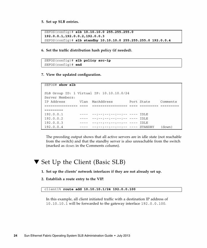
5. Set up SLB entries.
6. Set the traffic distribution hash policy (if needed).
7. View the updated configuration.
The preceding output shows that all active servers are in idle state (not reachablefrom the switch) and that the standby server is also unreachable from the switch(marked as down in the Comments column).
▼ Set Up the Client (Basic SLB)1. Set up the clients’ network interfaces if they are not already set up.
2. Establish a route entry to the VIP.
In this example, all client initiated traffic with a destination IP address of10.10.10.1 will be forwarded to the gateway interface 192.0.0.100.
SEFOS(config)# slb 10.10.10.0 255.255.255.0192.0.0.1,192.0.0.2,192.0.0.3SEFOS(config)# slb standby 10.10.10.0 255.255.255.0 192.0.0.4
SEFOS(config)# slb policy src-ipSEFOS(config)# end
SEFOS# show slb
SLB Group ID: 1 Virtual IP: 10.10.10.0/24Server Members:IP Address Vlan MacAddress Port State Comments================ ==== ================= ==== ========= ==================192.0.0.1 ---- --:--:--:--:--:-- ---- IDLE192.0.0.2 ---- --:--:--:--:--:-- ---- IDLE192.0.0.3 ---- --:--:--:--:--:-- ---- IDLE192.0.0.4 ---- --:--:--:--:--:-- ---- STANDBY (down)
client1% route add 10.10.10.1/24 192.0.0.100
24 Sun Ethernet Fabric Operating System SLB Administration Guide • July 2013

▼ Set Up the Server (Basic SLB)Each server must have a minimum of two interfaces set up, one interface for theactual device and another interface for a loopback used as an IP address alias.
1. Set up the physical interface.
2. Set up the loopback interface.
▼ Enable the Switch Ports (Basic SLB)Before you enable the switch ports on the network, ensure that you have set up theswitch, the server, and the client for each server in the SLB group, as described in theprevious sections.
1. Enable the switch ports on the server network.
2. Enable the switch ports on the client network.
server1% ifconfig ixgbe0 plumbserver1% ifconfig ixgbe0 192.0.0.1 netmask 255.255.255.0 up
server1% ifconfig lo0:1 plumbserver1% ifconfig lo0:1 10.10.10.1 netmask 255.255.255.0 up
server1% ifconfig -a
lo0:1:flags=2001000849<UP,LOOPBACK,RUNNING,MULTICAST,IPv4,VIRTUAL> mtu 8232index 1 inet 10.10.10.1 netmask ffffff00ixgbe0: flags=1000843<UP,BROADCAST,RUNNING,MULTICAST,IPv4> mtu1500 index 3 inet 192.0.0.1 netmask ffffff00 broadcast 192.0.0.255 ether 0:1b:21:53:6e:e0
SEFOS# configure terminalSEFOS(config)# interface range extreme-ethernet 0/15-18SEFOS(config-if-range)# no shutdownSEFOS(config-if-range)# exit
SEFOS(config)# interface range extreme-ethernet 0/3-6SEFOS(config-if-range)# no shutdownSEFOS(config-if-range)# end
Creating Example SLB Configurations 25
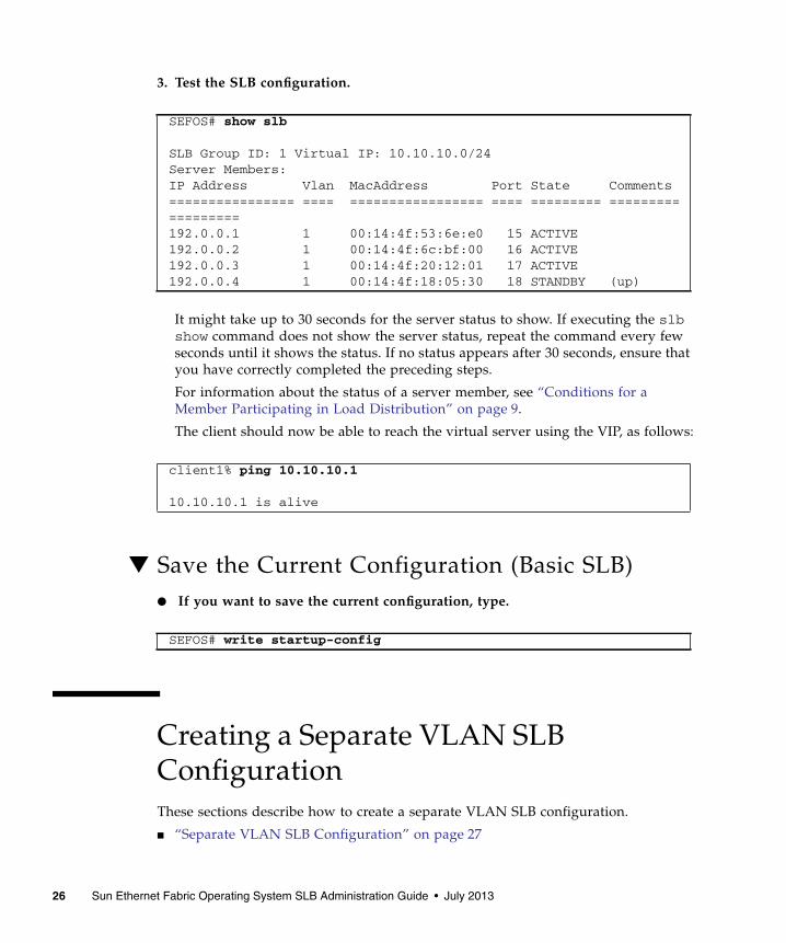
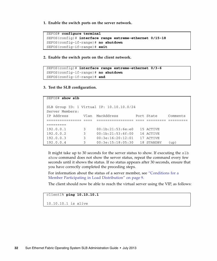
3. Test the SLB configuration.
It might take up to 30 seconds for the server status to show. If executing the slbshow command does not show the server status, repeat the command every fewseconds until it shows the status. If no status appears after 30 seconds, ensure thatyou have correctly completed the preceding steps.
For information about the status of a server member, see “Conditions for aMember Participating in Load Distribution” on page 9.
The client should now be able to reach the virtual server using the VIP, as follows:
▼ Save the Current Configuration (Basic SLB)● If you want to save the current configuration, type.
Creating a Separate VLAN SLBConfigurationThese sections describe how to create a separate VLAN SLB configuration.
■ “Separate VLAN SLB Configuration” on page 27
SEFOS# show slb
SLB Group ID: 1 Virtual IP: 10.10.10.0/24Server Members:IP Address Vlan MacAddress Port State Comments================ ==== ================= ==== ========= ==================192.0.0.1 1 00:14:4f:53:6e:e0 15 ACTIVE192.0.0.2 1 00:14:4f:6c:bf:00 16 ACTIVE192.0.0.3 1 00:14:4f:20:12:01 17 ACTIVE192.0.0.4 1 00:14:4f:18:05:30 18 STANDBY (up)
client1% ping 10.10.10.1
10.10.10.1 is alive
SEFOS# write startup-config
26 Sun Ethernet Fabric Operating System SLB Administration Guide • July 2013
■ “Configuration With Separate VLANs Steps” on page 28
■ “Set Up the Switch (Separate VLAN SLB)” on page 28
■ “Set Up the Client (Separate VLAN SLB)” on page 30
■ “Set Up the Server (Separate VLAN SLB)” on page 31
■ “Enable the Switch Ports (Separate VLAN SLB)” on page 31
■ “Save the Current Configuration (Separate VLAN SLB)” on page 33
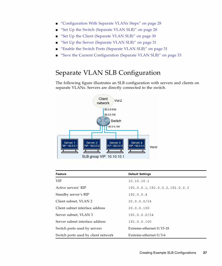
Separate VLAN SLB ConfigurationThe following figure illustrates an SLB configuration with servers and clients onseparate VLANs. Servers are directly connected to the switch.
Feature Default Settings
VIP 10.10.10.1
Active servers’ RIP 192.0.0.1, 192.0.0.2, 192.0.0.3
Standby server’s RIP 192.0.0.4
Client subnet, VLAN 2 20.0.0.0/24
Client subnet interface address 20.0.0.100
Server subnet, VLAN 3 192.0.0.0/24
Server subnet interface address 192.0.0.100
Switch ports used by servers Extreme-ethernet 0/15-18
Switch ports used by client network Extreme-ethernet 0/3-6
Creating Example SLB Configurations 27

Configuration With Separate VLANs StepsThis example shows the SLB configuration with servers and clients on separateVLANs. Servers are directly connected to the switch.
Use these steps to create this type of SLB configuration:
▼ Set Up the Switch (Separate VLAN SLB)Shut down SLB-related switch ports on the switch.
1. Disable GVRP and GMRP.
2. Enter Global Configuration mode so you can shut down SLB-related switchports on the switch.
Network interface for both servers ixgbe0
Step Description Links
1. Set up the switch. “Set Up the Switch (Separate VLAN SLB)” onpage 28
2. Set up the client. (Repeat this stepfor each client in the clientnetwork.)
“Set Up the Client (Separate VLAN SLB)” onpage 30
3. Set up the server. (Repeat this stepfor each server in the SLB group.)
“Set Up the Server (Separate VLAN SLB)” onpage 31
4. Enable the switch ports. “Enable the Switch Ports (Separate VLANSLB)” on page 31
5. Save the current configuration ifnecessary.
SEFOS(config)# set gvrp disableSEFOS(config)# set gmrp disable
SEFOS# configure terminal
Feature Default Settings
28 Sun Ethernet Fabric Operating System SLB Administration Guide • July 2013

3. Shut down switch ports connected to the client network.
4. Shut down switch ports connected to servers.
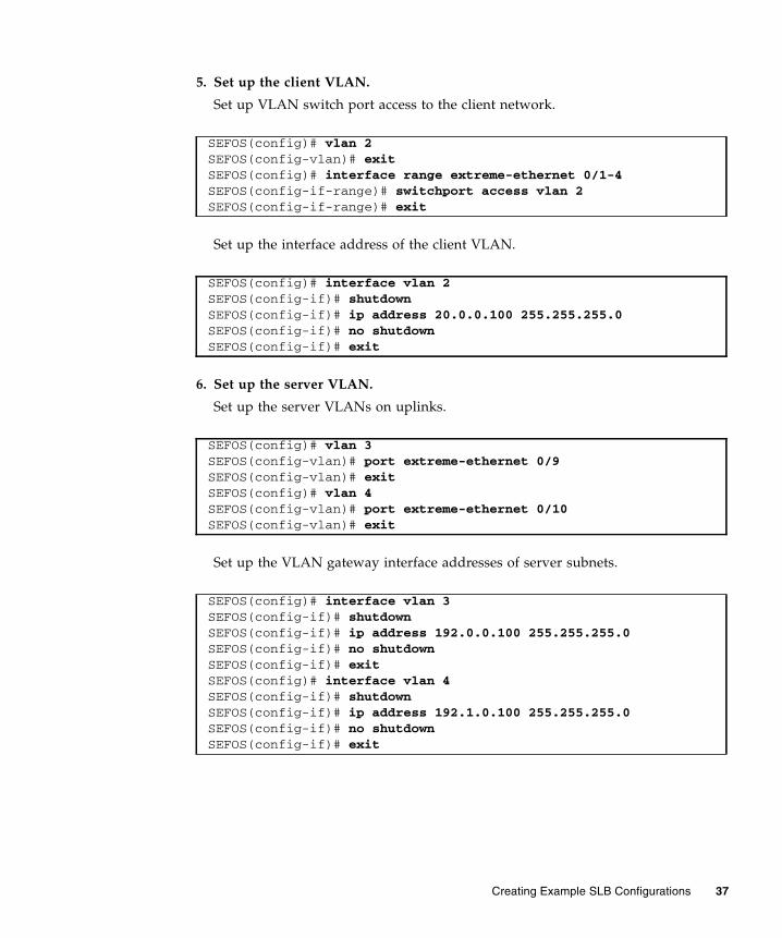
5. Set up the client VLAN.
Set up switch port access of the client network.
Set up interface address of the client VLAN.
6. Set up the server VLAN.
Set up VLAN switch port access for the server network.
Set up interface address of the server VLAN.
SEFOS(config)# interface range extreme-ethernet 0/3-6SEFOS(config-if-range)# shutdownSEFOS(config-if-range)# exit
SEFOS(config)# interface range extreme-ethernet 0/15-18SEFOS(config-if-range)# shutdownSEFOS(config-if-range)# exit
SEFOS(config)# vlan 2SEFOS(config-vlan)# exitSEFOS(config)# interface range extreme-ethernet 0/3-6SEFOS(config-if-range)# switchport access vlan 2SEFOS(config-if-range)# exit
SEFOS(config)# interface vlan 2SEFOS(config-if)# shutdownSEFOS(config-if)# ip address 20.0.0.100 255.255.255.0SEFOS(config-if)# no shutdownSEFOS(config-if)# exit
SEFOS(config)# vlan 3SEFOS(config-vlan)# exitSEFOS(config)# interface range extreme-ethernet 0/15-18SEFOS(config-if-range)# switchport access vlan 3SEFOS(config-if-range)# exit
SEFOS(config)# interface vlan 3SEFOS(config-if)# shutdown
Creating Example SLB Configurations 29
7. Set up SLB entries.
8. Set the traffic distribution hash policy (if needed).
9. View the updated configuration.
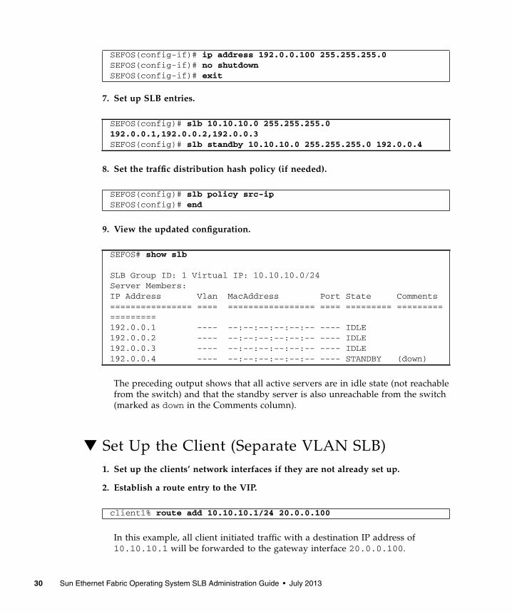
The preceding output shows that all active servers are in idle state (not reachablefrom the switch) and that the standby server is also unreachable from the switch(marked as down in the Comments column).
▼ Set Up the Client (Separate VLAN SLB)1. Set up the clients’ network interfaces if they are not already set up.
2. Establish a route entry to the VIP.
In this example, all client initiated traffic with a destination IP address of10.10.10.1 will be forwarded to the gateway interface 20.0.0.100.
SEFOS(config-if)# ip address 192.0.0.100 255.255.255.0SEFOS(config-if)# no shutdownSEFOS(config-if)# exit
SEFOS(config)# slb 10.10.10.0 255.255.255.0192.0.0.1,192.0.0.2,192.0.0.3SEFOS(config)# slb standby 10.10.10.0 255.255.255.0 192.0.0.4
SEFOS(config)# slb policy src-ipSEFOS(config)# end
SEFOS# show slb
SLB Group ID: 1 Virtual IP: 10.10.10.0/24Server Members:IP Address Vlan MacAddress Port State Comments================ ==== ================= ==== ========= ==================192.0.0.1 ---- --:--:--:--:--:-- ---- IDLE192.0.0.2 ---- --:--:--:--:--:-- ---- IDLE192.0.0.3 ---- --:--:--:--:--:-- ---- IDLE192.0.0.4 ---- --:--:--:--:--:-- ---- STANDBY (down)
client1% route add 10.10.10.1/24 20.0.0.100
30 Sun Ethernet Fabric Operating System SLB Administration Guide • July 2013

3. If the clients need to reach the physical server’s subnet using the servers’ RIPs,add the following route.
▼ Set Up the Server (Separate VLAN SLB)Each server must have a minimum of two interfaces set up, one interface for theactual device and another interface for a loopback used as an IP address alias.
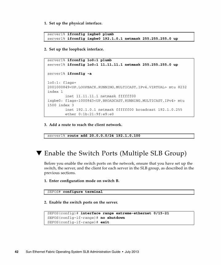
1. Set up the physical interface.
2. Set up the loopback interface.
3. Add a route to reach the client network.
▼ Enable the Switch Ports (Separate VLAN SLB)Before you enable the switch ports on the network, ensure that you have set up theswitch, the server, and the client for each server in the SLB group, as described in theprevious sections.
client1% route add 192.0.0.0/24 20.0.0.100
server1% ifconfig ixgbe0 plumbserver1% ifconfig ixgbe0 192.0.0.1 netmask 255.255.255.0 up
server1% ifconfig lo0:1 plumbserver1% ifconfig lo0:1 10.10.10.1 netmask 255.255.255.0 up
server1% ifconfig -a
lo0:1:flags=2001000849<UP,LOOPBACK,RUNNING,MULTICAST,IPv4,VIRTUAL> mtu 8232index 1 inet 10.10.10.1 netmask ffffff00ixgbe0: flags=1000843<UP,BROADCAST,RUNNING,MULTICAST,IPv4> mtu1500 index 3 inet 192.0.0.1 netmask ffffff00 broadcast 192.0.0.255 ether 0:1b:21:53:6e:e0
server1% route add 20.0.0.0/24 192.0.0.100
Creating Example SLB Configurations 31
1. Enable the switch ports on the server network.
2. Enable the switch ports on the client network.
3. Test the SLB configuration.
It might take up to 30 seconds for the server status to show. If executing the slbshow command does not show the server status, repeat the command every fewseconds until it shows the status. If no status appears after 30 seconds, ensure thatyou have correctly completed the preceding steps.
For information about the status of a server member, see “Conditions for aMember Participating in Load Distribution” on page 9.
The client should now be able to reach the virtual server using the VIP, as follows:
SEFOS# configure terminalSEFOS(config)# interface range extreme-ethernet 0/15-18SEFOS(config-if-range)# no shutdownSEFOS(config-if-range)# exit
SEFOS(config)# interface range extreme-ethernet 0/3-6SEFOS(config-if-range)# no shutdownSEFOS(config-if-range)# end
SEFOS# show slb
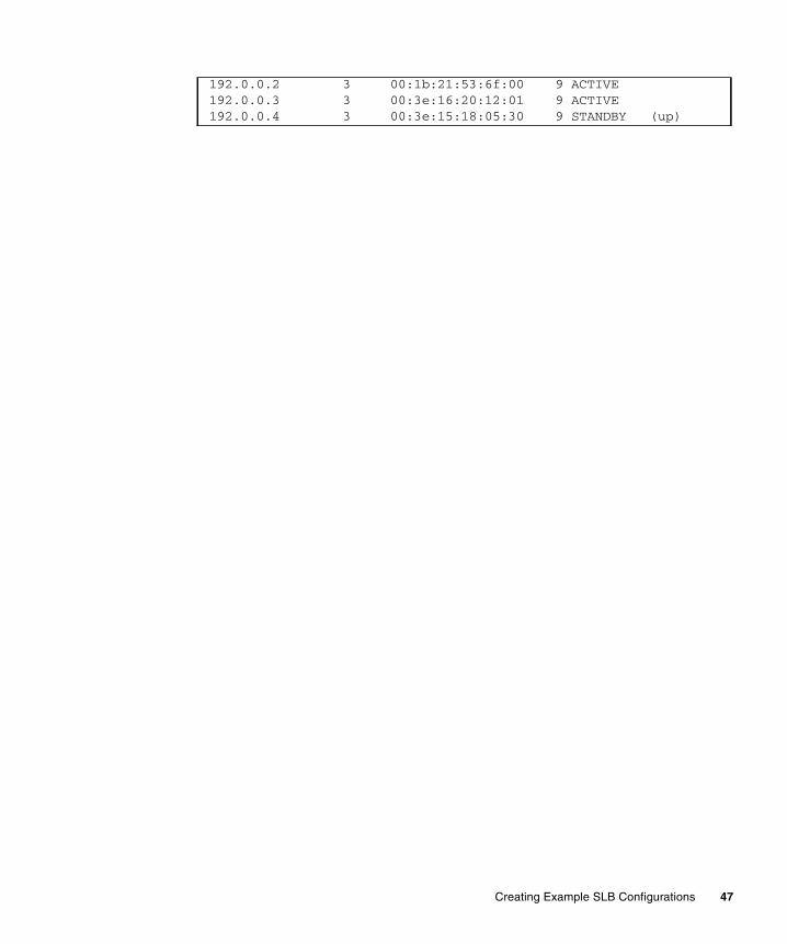
SLB Group ID: 1 Virtual IP: 10.10.10.0/24Server Members:IP Address Vlan MacAddress Port State Comments================ ==== ================= ==== ========= ==================192.0.0.1 3 00:1b:21:53:6e:e0 15 ACTIVE192.0.0.2 3 00:1b:21:53:6f:00 16 ACTIVE192.0.0.3 3 00:3e:16:20:12:01 17 ACTIVE192.0.0.4 3 00:3e:15:18:05:30 18 STANDBY (up)
client1% ping 10.10.10.1
10.10.10.1 is alive
32 Sun Ethernet Fabric Operating System SLB Administration Guide • July 2013

▼ Save the Current Configuration (Separate VLANSLB)● If you want to save the current configuration, type.
Creating a Multiple SLB GroupConfigurationThese sections describe how to create a multiple SLB group configuration.
■ “Multiple-SLB-Group Configuration” on page 33
■ “Configuration With Multiple SLB Groups Steps” on page 35
■ “Set Up Switch A” on page 36
■ “Set Up Switch B” on page 39
■ “Set Up the Client (Multiple SLB Group)” on page 40
■ “Set Up the Servers in SLB Group 1” on page 41
■ “Set Up the Servers in SLB Group 2” on page 41
■ “Enable the Switch Ports (Multiple SLB Group)” on page 42
■ “Save the Current Configuration (Multiple SLB Group)” on page 45
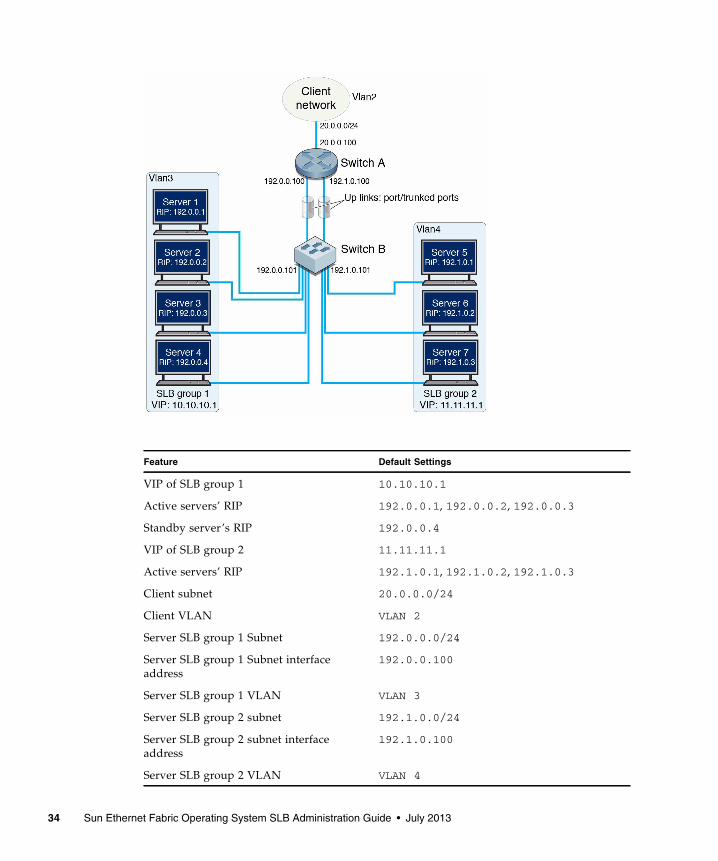
Multiple-SLB-Group ConfigurationThis example shows the SLB configuration with servers configured as multiple SLBgroups. Servers and clients are at multiple VLANs, and the servers are indirectlyattached to the switch.
SEFOS# write startup-config
Creating Example SLB Configurations 33
Feature Default Settings
VIP of SLB group 1 10.10.10.1
Active servers’ RIP 192.0.0.1, 192.0.0.2, 192.0.0.3
Standby server’s RIP 192.0.0.4
VIP of SLB group 2 11.11.11.1
Active servers’ RIP 192.1.0.1, 192.1.0.2, 192.1.0.3
Client subnet 20.0.0.0/24
Client VLAN VLAN 2
Server SLB group 1 Subnet 192.0.0.0/24
Server SLB group 1 Subnet interfaceaddress
192.0.0.100
Server SLB group 1 VLAN VLAN 3
Server SLB group 2 subnet 192.1.0.0/24
Server SLB group 2 subnet interfaceaddress
192.1.0.100
Server SLB group 2 VLAN VLAN 4
34 Sun Ethernet Fabric Operating System SLB Administration Guide • July 2013
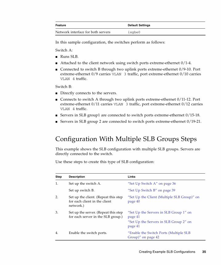
In this sample configuration, the switches perform as follows:
Switch A:
■ Runs SLB.
■ Attached to the client network using switch ports extreme-ethernet 0/1-4.
■ Connected to switch B through two uplink ports extreme-ethernet 0/9-10. Portextreme-ethernet 0/9 carries VLAN 3 traffic, port extreme-ethernet 0/10 carriesVLAN 4 traffic.
Switch B:
■ Directly connects to the servers.
■ Connects to switch A through two uplink ports extreme-ethernet 0/11-12. Portextreme-ethernet 0/11 carries VLAN 3 traffic, port extreme-ethernet 0/12 carriesVLAN 4 traffic.
■ Servers in SLB group1 are connected to switch ports extreme-ethernet 0/15-18.
■ Servers in SLB group 2 are connected to switch ports extreme-ethernet 0/19-21.
Configuration With Multiple SLB Groups StepsThis example shows the SLB configuration with multiple SLB groups. Servers aredirectly connected to the switch.
Use these steps to create this type of SLB configuration:
Network interface for both servers ixgbe0
Step Description Links
1. Set up the switch A. “Set Up Switch A” on page 36
Set up switch B. “Set Up Switch B” on page 39
2. Set up the client. (Repeat this stepfor each client in the clientnetwork.)
“Set Up the Client (Multiple SLB Group)” onpage 40
3. Set up the server. (Repeat this stepfor each server in the SLB group.)
“Set Up the Servers in SLB Group 1” onpage 41“Set Up the Servers in SLB Group 2” onpage 41
4. Enable the switch ports. “Enable the Switch Ports (Multiple SLBGroup)” on page 42
Feature Default Settings
Creating Example SLB Configurations 35
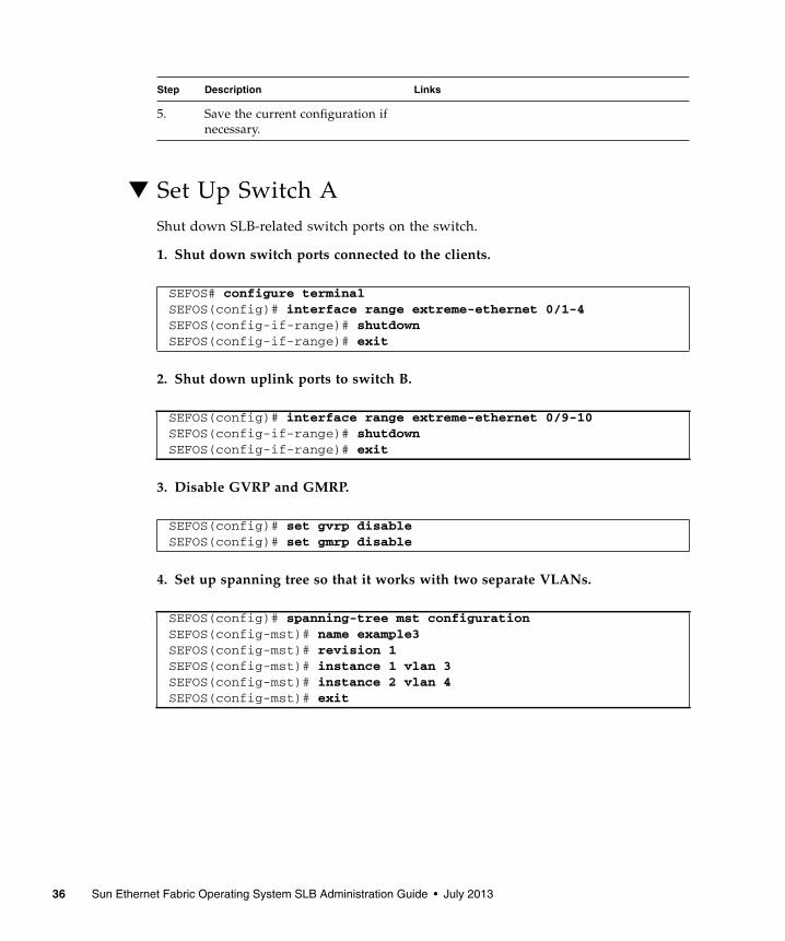
▼ Set Up Switch AShut down SLB-related switch ports on the switch.
1. Shut down switch ports connected to the clients.
2. Shut down uplink ports to switch B.
3. Disable GVRP and GMRP.
4. Set up spanning tree so that it works with two separate VLANs.
5. Save the current configuration ifnecessary.
SEFOS# configure terminalSEFOS(config)# interface range extreme-ethernet 0/1-4SEFOS(config-if-range)# shutdownSEFOS(config-if-range)# exit
SEFOS(config)# interface range extreme-ethernet 0/9-10SEFOS(config-if-range)# shutdownSEFOS(config-if-range)# exit
SEFOS(config)# set gvrp disableSEFOS(config)# set gmrp disable
SEFOS(config)# spanning-tree mst configurationSEFOS(config-mst)# name example3SEFOS(config-mst)# revision 1SEFOS(config-mst)# instance 1 vlan 3SEFOS(config-mst)# instance 2 vlan 4SEFOS(config-mst)# exit
Step Description Links
36 Sun Ethernet Fabric Operating System SLB Administration Guide • July 2013
5. Set up the client VLAN.
Set up VLAN switch port access to the client network.
Set up the interface address of the client VLAN.
6. Set up the server VLAN.
Set up the server VLANs on uplinks.
Set up the VLAN gateway interface addresses of server subnets.
SEFOS(config)# vlan 2SEFOS(config-vlan)# exitSEFOS(config)# interface range extreme-ethernet 0/1-4SEFOS(config-if-range)# switchport access vlan 2SEFOS(config-if-range)# exit
SEFOS(config)# interface vlan 2SEFOS(config-if)# shutdownSEFOS(config-if)# ip address 20.0.0.100 255.255.255.0SEFOS(config-if)# no shutdownSEFOS(config-if)# exit
SEFOS(config)# vlan 3SEFOS(config-vlan)# port extreme-ethernet 0/9SEFOS(config-vlan)# exitSEFOS(config)# vlan 4SEFOS(config-vlan)# port extreme-ethernet 0/10SEFOS(config-vlan)# exit
SEFOS(config)# interface vlan 3SEFOS(config-if)# shutdownSEFOS(config-if)# ip address 192.0.0.100 255.255.255.0SEFOS(config-if)# no shutdownSEFOS(config-if)# exitSEFOS(config)# interface vlan 4SEFOS(config-if)# shutdownSEFOS(config-if)# ip address 192.1.0.100 255.255.255.0SEFOS(config-if)# no shutdownSEFOS(config-if)# exit
Creating Example SLB Configurations 37

7. Set up SLB entries.
Set up the first SLB group.
Set up the second SLB group.
8. Set the traffic distribution hash policy (if needed).
9. View the updated configuration.
The preceding output shows that all active servers are in idle state (not reachablefrom the switch) and that the standby server is also unreachable from the switch(marked as down in the Comments column).
SEFOS(config)# slb 10.10.10.0 255.255.255.0192.0.0.1,192.0.0.2,192.0.0.3SEFOS(config)# slb standby 10.10.10.0 255.255.255.0 192.0.0.4
SEFOS(config)# slb 11.11.11.0 255.255.255.0192.1.0.1,192.1.0.2,192.1.0.3
SEFOS(config)# slb policy src-ipSEFOS(config)# end
SEFOS# show slb
SLB Group ID: 1 Virtual IP: 10.10.10.0/24Server Members:IP Address Vlan MacAddress Port State Comments================ ==== ================= ==== ========= ==================192.0.0.1 ---- --:--:--:--:--:-- ---- IDLE192.0.0.2 ---- --:--:--:--:--:-- ---- IDLE192.0.0.3 ---- --:--:--:--:--:-- ---- IDLE192.0.0.4 ---- --:--:--:--:--:-- ---- STANDBY (down)
SLB Group ID: 2 Virtual IP: 11.11.11.0/24Server Members:IP Address Vlan MacAddress Port State Comments================ ==== ================= ==== ========= ==================192.1.0.1 ---- --:--:--:--:--:-- ---- IDLE192.1.0.2 ---- --:--:--:--:--:-- ---- IDLE192.1.0.3 ---- --:--:--:--:--:-- ---- IDLE
38 Sun Ethernet Fabric Operating System SLB Administration Guide • July 2013
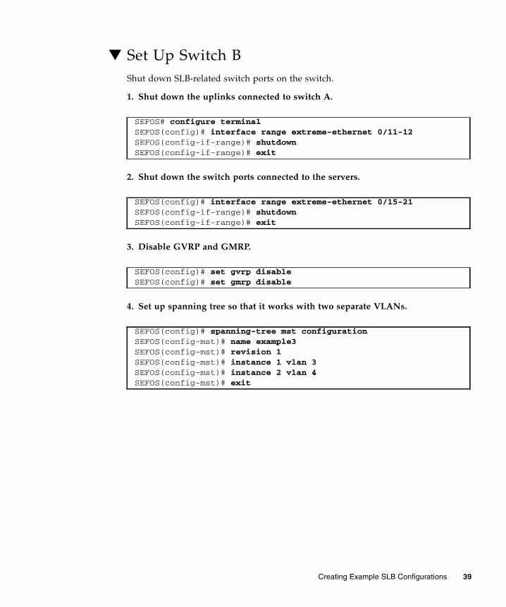
▼ Set Up Switch BShut down SLB-related switch ports on the switch.
1. Shut down the uplinks connected to switch A.
2. Shut down the switch ports connected to the servers.
3. Disable GVRP and GMRP.
4. Set up spanning tree so that it works with two separate VLANs.
SEFOS# configure terminalSEFOS(config)# interface range extreme-ethernet 0/11-12SEFOS(config-if-range)# shutdownSEFOS(config-if-range)# exit
SEFOS(config)# interface range extreme-ethernet 0/15-21SEFOS(config-if-range)# shutdownSEFOS(config-if-range)# exit
SEFOS(config)# set gvrp disableSEFOS(config)# set gmrp disable
SEFOS(config)# spanning-tree mst configurationSEFOS(config-mst)# name example3SEFOS(config-mst)# revision 1SEFOS(config-mst)# instance 1 vlan 3SEFOS(config-mst)# instance 2 vlan 4SEFOS(config-mst)# exit
Creating Example SLB Configurations 39
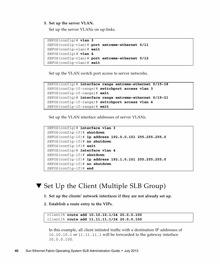
5. Set up the server VLAN.
Set up the server VLANs on up-links.
Set up the VLAN switch port access to server networks.
Set up the VLAN interface addresses of server VLANs.
▼ Set Up the Client (Multiple SLB Group)1. Set up the clients’ network interfaces if they are not already set up.
2. Establish a route entry to the VIPs.
In this example, all client initiated traffic with a destination IP addresses of10.10.10.1 or 11.11.11.1 will be forwarded to the gateway interface20.0.0.100.
SEFOS(config)# vlan 3SEFOS(config-vlan)# port extreme-ethernet 0/11SEFOS(config-vlan)# exitSEFOS(config)# vlan 4SEFOS(config-vlan)# port extreme-ethernet 0/12SEFOS(config-vlan)# exit
SEFOS(config)# interface range extreme-ethernet 0/15-18SEFOS(config-if-range)# switchport access vlan 3SEFOS(config-if-range)# exitSEFOS(config)# interface range extreme-ethernet 0/19-21SEFOS(config-if-range)# switchport access vlan 4SEFOS(config-if-range)# exit
SEFOS(config)# interface vlan 3SEFOS(config-if)# shutdownSEFOS(config-if)# ip address 192.0.0.101 255.255.255.0SEFOS(config-if)# no shutdownSEFOS(config-if)# exitSEFOS(config)# interface vlan 4SEFOS(config-if)# shutdownSEFOS(config-if)# ip address 192.1.0.101 255.255.255.0SEFOS(config-if)# no shutdownSEFOS(config-if)# end
client1% route add 10.10.10.1/24 20.0.0.100client1% route add 11.11.11.1/24 20.0.0.100
40 Sun Ethernet Fabric Operating System SLB Administration Guide • July 2013
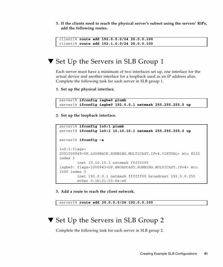
3. If the clients need to reach the physical server’s subnet using the servers’ RIPs,add the following routes.
▼ Set Up the Servers in SLB Group 1Each server must have a minimum of two interfaces set up, one interface for theactual device and another interface for a loopback used as an IP address alias.Complete the following task for each server in SLB group 1.
1. Set up the physical interface.
2. Set up the loopback interface.
3. Add a route to reach the client network.
▼ Set Up the Servers in SLB Group 2Complete the following task for each server in SLB group 2.
client1% route add 192.0.0.0/24 20.0.0.100client1% route add 192.1.0.0/24 20.0.0.100
server1% ifconfig ixgbe0 plumbserver1% ifconfig ixgbe0 192.0.0.1 netmask 255.255.255.0 up
server1% ifconfig lo0:1 plumbserver1% ifconfig lo0:1 10.10.10.1 netmask 255.255.255.0 up
server1% ifconfig -a
lo0:1:flags=2001000849<UP,LOOPBACK,RUNNING,MULTICAST,IPv4,VIRTUAL> mtu 8232index 1 inet 10.10.10.1 netmask ffffff00ixgbe0: flags=1000843<UP,BROADCAST,RUNNING,MULTICAST,IPv4> mtu1500 index 3 inet 192.0.0.1 netmask ffffff00 broadcast 192.0.0.255 ether 0:1b:21:53:6e:e0
server1% route add 20.0.0.0/24 192.0.0.100
Creating Example SLB Configurations 41
1. Set up the physical interface.
2. Set up the loopback interface.
3. Add a route to reach the client network.
▼ Enable the Switch Ports (Multiple SLB Group)Before you enable the switch ports on the network, ensure that you have set up theswitch, the server, and the client for each server in the SLB group, as described in theprevious sections.
1. Enter configuration mode on switch B.
2. Enable the switch ports on the server.
server1% ifconfig ixgbe0 plumbserver1% ifconfig ixgbe0 192.1.0.1 netmask 255.255.255.0 up
server1% ifconfig lo0:1 plumbserver1% ifconfig lo0:1 11.11.11.1 netmask 255.255.255.0 up
server1% ifconfig -a
lo0:1: flags=2001000849<UP,LOOPBACK,RUNNING,MULTICAST,IPv4,VIRTUAL> mtu 8232index 1 inet 11.11.11.1 netmask ffffff00ixgbe0: flags=1000843<UP,BROADCAST,RUNNING,MULTICAST,IPv4> mtu1500 index 3 inet 192.1.0.1 netmask ffffff00 broadcast 192.1.0.255 ether 0:1b:21:9f:e9:e0
server1% route add 20.0.0.0/24 192.1.0.100
SEFOS# configure terminal
SEFOS(config)# interface range extreme-ethernet 0/15-21SEFOS(config-if-range)# no shutdownSEFOS(config-if-range)# exit
42 Sun Ethernet Fabric Operating System SLB Administration Guide • July 2013

3. Enable the uplinks to switch A.
4. Enter configuration mode on switch A.
5. Enable the uplinks to switch B.
6. Enable the client network.
SEFOS(config)# interface range extreme-ethernet 0/11-12SEFOS(config-if-range)# no shutdownSEFOS(config-if-range)# end
SEFOS# configure terminal
SEFOS(config)# interface range extreme-ethernet 0/9-10SEFOS(config-if-range)# no shutdownSEFOS(config-if-range)# end
SEFOS(config)# interface range extreme-ethernet 0/1-4SEFOS(config-if-range)# no shutdownSEFOS(config-if-range)# end
Creating Example SLB Configurations 43
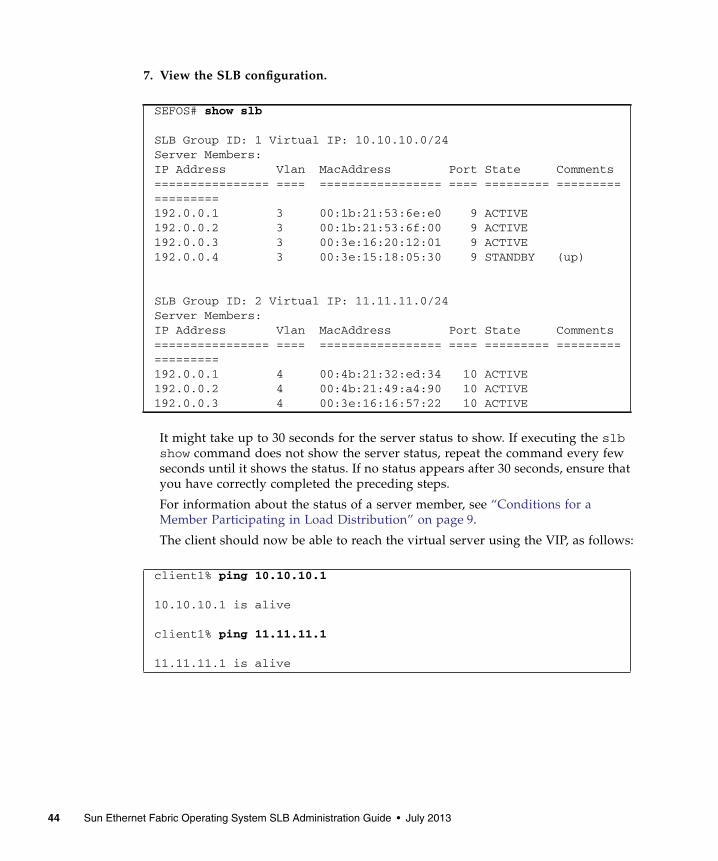
7. View the SLB configuration.
It might take up to 30 seconds for the server status to show. If executing the slbshow command does not show the server status, repeat the command every fewseconds until it shows the status. If no status appears after 30 seconds, ensure thatyou have correctly completed the preceding steps.
For information about the status of a server member, see “Conditions for aMember Participating in Load Distribution” on page 9.
The client should now be able to reach the virtual server using the VIP, as follows:
SEFOS# show slb
SLB Group ID: 1 Virtual IP: 10.10.10.0/24Server Members:IP Address Vlan MacAddress Port State Comments================ ==== ================= ==== ========= ==================192.0.0.1 3 00:1b:21:53:6e:e0 9 ACTIVE192.0.0.2 3 00:1b:21:53:6f:00 9 ACTIVE192.0.0.3 3 00:3e:16:20:12:01 9 ACTIVE192.0.0.4 3 00:3e:15:18:05:30 9 STANDBY (up)
SLB Group ID: 2 Virtual IP: 11.11.11.0/24Server Members:IP Address Vlan MacAddress Port State Comments================ ==== ================= ==== ========= ==================192.0.0.1 4 00:4b:21:32:ed:34 10 ACTIVE192.0.0.2 4 00:4b:21:49:a4:90 10 ACTIVE192.0.0.3 4 00:3e:16:16:57:22 10 ACTIVE
client1% ping 10.10.10.1
10.10.10.1 is alive
client1% ping 11.11.11.1
11.11.11.1 is alive
44 Sun Ethernet Fabric Operating System SLB Administration Guide • July 2013
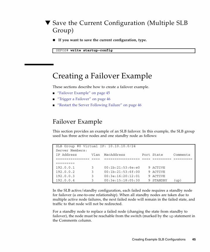
▼ Save the Current Configuration (Multiple SLBGroup)● If you want to save the current configuration, type.
Creating a Failover ExampleThese sections describe how to create a failover example.
■ “Failover Example” on page 45
■ “Trigger a Failover” on page 46
■ “Restart the Server Following Failure” on page 46
Failover ExampleThis section provides an example of an SLB failover. In this example, the SLB groupused has three active nodes and one standby node as follows:
In the SLB active/standby configuration, each failed node requires a standby nodefor failover (a one-to-one relationship). When all standby nodes are taken due tomultiple active node failures, the next failed node will remain in the failed state, andtraffic to that node will not be redirected.
For a standby node to replace a failed node (changing the state from standby tofailover), the node must be reachable from the switch (marked by the up statement inthe Comments column.
SEFOS# write startup-config
SLB Group #0 Virtual IP: 10.10.10.0/24Server Members:IP Address Vlan MacAddress Port State Comments================ ==== ================= ==== ========= ==================192.0.0.1 3 00:1b:21:53:6e:e0 9 ACTIVE192.0.0.2 3 00:1b:21:53:6f:00 9 ACTIVE192.0.0.3 3 00:3e:16:20:12:01 9 ACTIVE192.0.0.4 3 00:3e:15:18:05:30 9 STANDBY (up)
Creating Example SLB Configurations 45
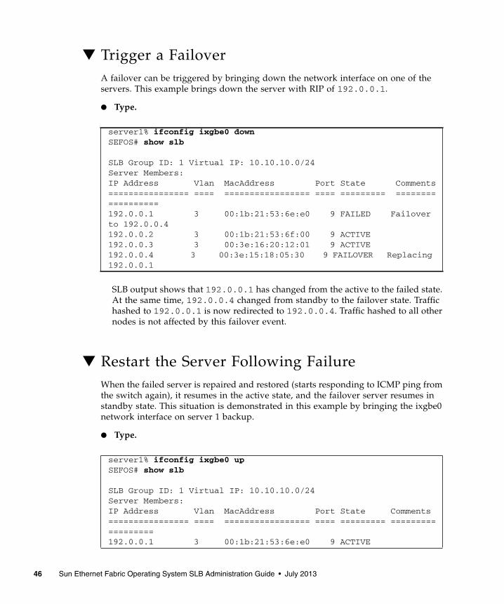
▼ Trigger a FailoverA failover can be triggered by bringing down the network interface on one of theservers. This example brings down the server with RIP of 192.0.0.1.
● Type.
SLB output shows that 192.0.0.1 has changed from the active to the failed state.At the same time, 192.0.0.4 changed from standby to the failover state. Traffichashed to 192.0.0.1 is now redirected to 192.0.0.4. Traffic hashed to all othernodes is not affected by this failover event.
▼ Restart the Server Following FailureWhen the failed server is repaired and restored (starts responding to ICMP ping fromthe switch again), it resumes in the active state, and the failover server resumes instandby state. This situation is demonstrated in this example by bringing the ixgbe0network interface on server 1 backup.
● Type.
server1% ifconfig ixgbe0 downSEFOS# show slb
SLB Group ID: 1 Virtual IP: 10.10.10.0/24Server Members:IP Address Vlan MacAddress Port State Comments================ ==== ================= ==== ========= ==================192.0.0.1 3 00:1b:21:53:6e:e0 9 FAILED Failoverto 192.0.0.4192.0.0.2 3 00:1b:21:53:6f:00 9 ACTIVE192.0.0.3 3 00:3e:16:20:12:01 9 ACTIVE192.0.0.4 3 00:3e:15:18:05:30 9 FAILOVER Replacing192.0.0.1
server1% ifconfig ixgbe0 upSEFOS# show slb
SLB Group ID: 1 Virtual IP: 10.10.10.0/24Server Members:IP Address Vlan MacAddress Port State Comments================ ==== ================= ==== ========= ==================192.0.0.1 3 00:1b:21:53:6e:e0 9 ACTIVE
46 Sun Ethernet Fabric Operating System SLB Administration Guide • July 2013
192.0.0.2 3 00:1b:21:53:6f:00 9 ACTIVE192.0.0.3 3 00:3e:16:20:12:01 9 ACTIVE192.0.0.4 3 00:3e:15:18:05:30 9 STANDBY (up)
Creating Example SLB Configurations 47

48 Sun Ethernet Fabric Operating System SLB Administration Guide • July 2013
Creating SLB-L2 ConfigurationExamples
These sections provide examples for a basic SLB configuration, a configuration withseparate VLANs, and a configuration with multiple SLB groups. All host commandlines are shown in the Oracle Solaris OS.
■ “Bump-In-The-Wire Configuration” on page 49
■ “Creating a Single-Switch Configuration” on page 49
■ “Creating a Dual-Switch Configuration” on page 56
■ “Creating an SLB-L2 Failover Example” on page 63
Bump-In-The-Wire ConfigurationA common use case of SLB-L2 is the bump-in-the-wire configuration. The "bumps"are servers processing nodes that can run applications such as a firewall, packetfiltering, and data interception.
Creating a Single-Switch ConfigurationThese sections describes how to create a single-switch configuration.
■ “Basic Single-Switch Configuration” on page 50
■ “Create a Single-Switch Configuration” on page 50
49
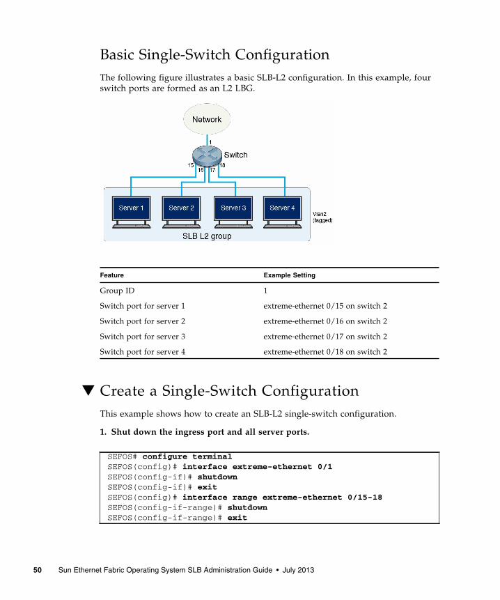
Basic Single-Switch ConfigurationThe following figure illustrates a basic SLB-L2 configuration. In this example, fourswitch ports are formed as an L2 LBG.
▼ Create a Single-Switch ConfigurationThis example shows how to create an SLB-L2 single-switch configuration.
1. Shut down the ingress port and all server ports.
Feature Example Setting
Group ID 1
Switch port for server 1 extreme-ethernet 0/15 on switch 2
Switch port for server 2 extreme-ethernet 0/16 on switch 2
Switch port for server 3 extreme-ethernet 0/17 on switch 2
Switch port for server 4 extreme-ethernet 0/18 on switch 2
SEFOS# configure terminalSEFOS(config)# interface extreme-ethernet 0/1SEFOS(config-if)# shutdownSEFOS(config-if)# exitSEFOS(config)# interface range extreme-ethernet 0/15-18SEFOS(config-if-range)# shutdownSEFOS(config-if-range)# exit
50 Sun Ethernet Fabric Operating System SLB Administration Guide • July 2013

2. Disable GVRP and GMRP.
3. Form an LBG.
4. View the configuration.
All ports are in the idle state because the interface ports 15 through 18 are stilldisabled.
5. Set the LBG failover method (if different from the default).
6. Set the load distribution hash policy (if different from the default).
7. Set up the bump-in-the-wire configuration.
To set up the bump-in-the-wire configuration, you must use a VLAN tag toidentify ingress and egress traffic ports. This example associates the LBG and theingress/egress port with VLAN 2. The following steps set up VLAN membershipfor the ports that participate in the LBG and also set up the switch to insert theVLAN tag to outgoing packets from port 15-18.
SEFOS(config)# set gvrp disableSEFOS(config)# set gmrp disable
SEFOS(config)# slb l2 1 extreme-ethernet 0/15-18SEFOS(config-if-range)# exit
SEFOS# show slb l2
L2 SLB Group #1Failover Method: Failover to Standby Port(s) first, then All PortsPort Members:Port State Comments==== ===== ================= 15 IDLE 16 IDLE 17 IDLE 18 IDLE
SEFOS(config)# slb l2 failover-method 1 prefer-standby
SEFOS(config)# slb l2 policy src-ip
Creating SLB-L2 Configuration Examples 51
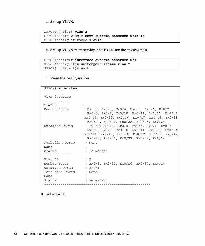
a. Set up VLAN.
b. Set up VLAN membership and PVID for the ingress port.
c. View the configuration.
8. Set up ACL.
SEFOS(config)# vlan 2SEFOS(config-vlan)# port extreme-ethernet 0/15-18SEFOS(config-if-range)# exit
SEFOS(config)# interface extreme-ethernet 0/1SEFOS(config-if)# switchport access vlan 2SEFOS(config-if)# exit
SEFOS# show vlan
Vlan database-------------Vlan ID : 1Member Ports : Ex0/2, Ex0/3, Ex0/4, Ex0/5, Ex0/6, Ex0/7 Ex0/8, Ex0/9, Ex0/10, Ex0/11, Ex0/12, Ex0/13
Ex0/14, Ex0/15, Ex0/16, Ex0/17, Ex0/18, Ex0/19 Ex0/20, Ex0/21, Ex0/22, Ex0/23, Ex0/24Untagged Ports : Ex0/2, Ex0/3, Ex0/4, Ex0/5, Ex0/6, Ex0/7 Ex0/8, Ex0/9, Ex0/10, Ex0/11, Ex0/12, Ex0/13
Ex0/14, Ex0/15, Ex0/16, Ex0/17, Ex0/18, Ex0/19 Ex0/20, Ex0/21, Ex0/22, Ex0/23, Ex0/24Forbidden Ports : NoneName :Status : Permanent-------------Vlan ID : 2Member Ports : Ex0/1, Ex0/15, Ex0/16, Ex0/17, Ex0/18Untagged Ports : Ex0/1Forbidden Ports : NoneName :Status : Permanent----------------------------------------------------
52 Sun Ethernet Fabric Operating System SLB Administration Guide • July 2013
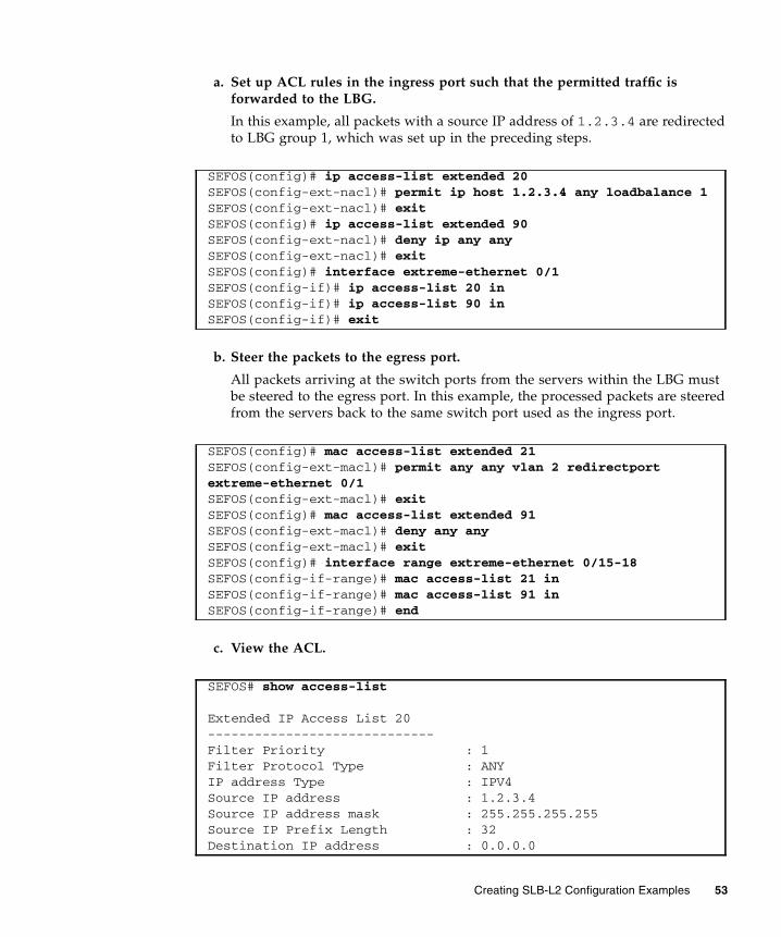
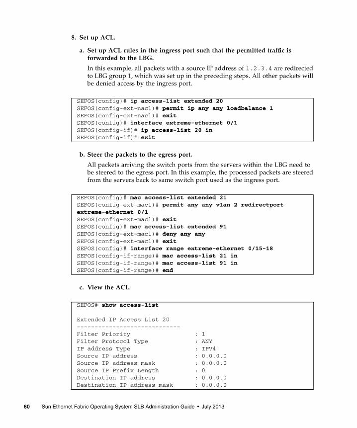
a. Set up ACL rules in the ingress port such that the permitted traffic isforwarded to the LBG.
In this example, all packets with a source IP address of 1.2.3.4 are redirectedto LBG group 1, which was set up in the preceding steps.
b. Steer the packets to the egress port.
All packets arriving at the switch ports from the servers within the LBG mustbe steered to the egress port. In this example, the processed packets are steeredfrom the servers back to the same switch port used as the ingress port.
c. View the ACL.
SEFOS(config)# ip access-list extended 20SEFOS(config-ext-nacl)# permit ip host 1.2.3.4 any loadbalance 1SEFOS(config-ext-nacl)# exitSEFOS(config)# ip access-list extended 90SEFOS(config-ext-nacl)# deny ip any anySEFOS(config-ext-nacl)# exitSEFOS(config)# interface extreme-ethernet 0/1SEFOS(config-if)# ip access-list 20 inSEFOS(config-if)# ip access-list 90 inSEFOS(config-if)# exit
SEFOS(config)# mac access-list extended 21SEFOS(config-ext-macl)# permit any any vlan 2 redirectportextreme-ethernet 0/1SEFOS(config-ext-macl)# exitSEFOS(config)# mac access-list extended 91SEFOS(config-ext-macl)# deny any anySEFOS(config-ext-macl)# exitSEFOS(config)# interface range extreme-ethernet 0/15-18SEFOS(config-if-range)# mac access-list 21 inSEFOS(config-if-range)# mac access-list 91 inSEFOS(config-if-range)# end
SEFOS# show access-list
Extended IP Access List 20-----------------------------Filter Priority : 1Filter Protocol Type : ANYIP address Type : IPV4Source IP address : 1.2.3.4Source IP address mask : 255.255.255.255Source IP Prefix Length : 32Destination IP address : 0.0.0.0
Creating SLB-L2 Configuration Examples 53
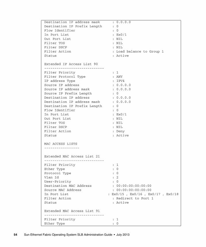
Destination IP address mask : 0.0.0.0Destination IP Prefix Length : 0Flow Identifier : 0In Port List : Ex0/1Out Port List : NILFilter TOS : NILFilter DSCP : NILFilter Action : Load balance to Group 1Status : Active
Extended IP Access List 90-----------------------------Filter Priority : 1Filter Protocol Type : ANYIP address Type : IPV4Source IP address : 0.0.0.0Source IP address mask : 0.0.0.0Source IP Prefix Length : 0Destination IP address : 0.0.0.0Destination IP address mask : 0.0.0.0Destination IP Prefix Length : 0Flow Identifier : 0In Port List : Ex0/1Out Port List : NILFilter TOS : NILFilter DSCP : NILFilter Action : DenyStatus : Active
MAC ACCESS LISTS-----------------
Extended MAC Access List 21-----------------------------Filter Priority : 1Ether Type : 0Protocol Type : 0Vlan Id : 2User-Priority : 0Destination MAC Address : 00:00:00:00:00:00Source MAC Address : 00:00:00:00:00:00In Port List : Ex0/15 , Ex0/16 , Ex0/17 , Ex0/18Filter Action : Redirect to Port 1Status : Active
Extended MAC Access List 91-----------------------------Filter Priority : 1Ether Type : 0
54 Sun Ethernet Fabric Operating System SLB Administration Guide • July 2013
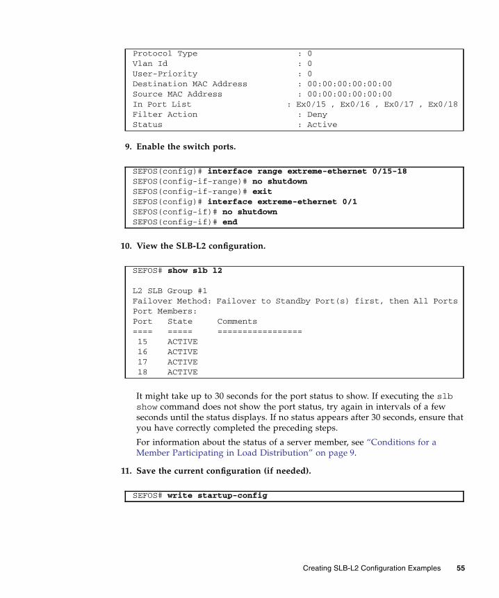
9. Enable the switch ports.
10. View the SLB-L2 configuration.
It might take up to 30 seconds for the port status to show. If executing the slbshow command does not show the port status, try again in intervals of a fewseconds until the status displays. If no status appears after 30 seconds, ensure thatyou have correctly completed the preceding steps.
For information about the status of a server member, see “Conditions for aMember Participating in Load Distribution” on page 9.
11. Save the current configuration (if needed).
Protocol Type : 0Vlan Id : 0User-Priority : 0Destination MAC Address : 00:00:00:00:00:00Source MAC Address : 00:00:00:00:00:00In Port List : Ex0/15 , Ex0/16 , Ex0/17 , Ex0/18Filter Action : DenyStatus : Active
SEFOS(config)# interface range extreme-ethernet 0/15-18SEFOS(config-if-range)# no shutdownSEFOS(config-if-range)# exitSEFOS(config)# interface extreme-ethernet 0/1SEFOS(config-if)# no shutdownSEFOS(config-if)# end
SEFOS# show slb l2
L2 SLB Group #1Failover Method: Failover to Standby Port(s) first, then All PortsPort Members:Port State Comments==== ===== ================= 15 ACTIVE 16 ACTIVE 17 ACTIVE 18 ACTIVE
SEFOS# write startup-config
Creating SLB-L2 Configuration Examples 55

Creating a Dual-Switch ConfigurationThese sections describe how to create a dual-switch configuration.
■ “Dual-Switch Configuration” on page 56
■ “Create a Dual-Switch Configuration” on page 57
Dual-Switch ConfigurationThis example shows a dual-switch configuration, with the servers configured inbetween the two switches as the "bump". Each server is dual-homed. LBGs areformed in a symmetric way (LBG on each switch has the same port members set upin the exact same order).
Feature Example Setting
Group ID 1
Switch port for server 1 extreme-ethernet 0/15 on switch 2
56 Sun Ethernet Fabric Operating System SLB Administration Guide • July 2013
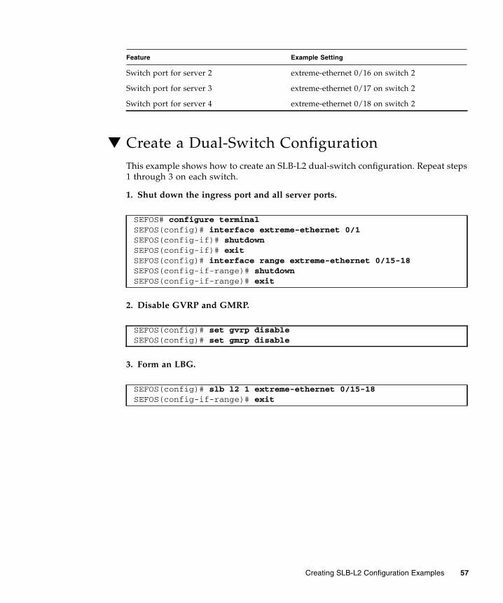
▼ Create a Dual-Switch ConfigurationThis example shows how to create an SLB-L2 dual-switch configuration. Repeat steps1 through 3 on each switch.
1. Shut down the ingress port and all server ports.
2. Disable GVRP and GMRP.
3. Form an LBG.
Switch port for server 2 extreme-ethernet 0/16 on switch 2
Switch port for server 3 extreme-ethernet 0/17 on switch 2
Switch port for server 4 extreme-ethernet 0/18 on switch 2
SEFOS# configure terminalSEFOS(config)# interface extreme-ethernet 0/1SEFOS(config-if)# shutdownSEFOS(config-if)# exitSEFOS(config)# interface range extreme-ethernet 0/15-18SEFOS(config-if-range)# shutdownSEFOS(config-if-range)# exit
SEFOS(config)# set gvrp disableSEFOS(config)# set gmrp disable
SEFOS(config)# slb l2 1 extreme-ethernet 0/15-18SEFOS(config-if-range)# exit
Feature Example Setting
Creating SLB-L2 Configuration Examples 57

4. View the configuration.
The same output will appear from group 2 after you run these commands onswitch 2.
All ports are in idle state because the interface ports 15 through 18 are stilldisabled.
5. Set the LBG failover method (if different from the default).
6. Set the load distribution hash policy.
To get forward and reverse traffic to be hashed to the same node (referred to ashash symmetry), you must choose a policy that includes the sym option. Useeither of the following methods to maintain hash symmetry.
This example includes both source and destination IP addresses for hashing in asymmetrical manner. The same hash results even if the source and destination IPaddresses are swapped.
Alternatively, you could maintain hash symmetry while using only the src-ipfield on switch A and the dest-ip field on switch B.
On switch A, type.
On switch B, type.
SEFOS# show slb l2
L2 SLB Group #1Failover Method: Failover to Standby Port(s) first, then All PortsPort Members:Port State Comments==== ===== ================= 15 IDLE 16 IDLE 17 IDLE 18 IDLE
SEFOS(config)# slb l2 failover-method 1 prefer-standby
SEFOS(config)# slb l2 policy src-ip dest-ip sym
SEFOS(config)# slb l2 policy src-ip sym
SEFOS(config)# slb l2 policy dest-ip sym
58 Sun Ethernet Fabric Operating System SLB Administration Guide • July 2013

7. Set up the bump-in-the-wire configuration.
To set up the bump-in-the-wire configuration, you must use a VLAN tag toidentify ingress and egress traffic ports. This example associates the LBG and theingress/egress port with VLAN 2. The following steps set up VLAN membershipfor the ports that participate in the LBG and also set up the switch to insert theVLAN tag to outgoing packets from port 15-18.
a. Set up VLAN.
b. Set up VLAN membership and PVID for the ingress port.
c. View the configuration.
SEFOS(config)# vlan 2SEFOS(config-vlan)# port extreme-ethernet 0/15-18SEFOS(config-if-range)# exit
SEFOS(config)# interface extreme-ethernet 0/1SEFOS(config-if)# switchport access vlan 2SEFOS(config-if)# exit
SEFOS# show vlan
Vlan database-------------Vlan ID : 1Member Ports : Ex0/2, Ex0/3, Ex0/4, Ex0/5, Ex0/6, Ex0/7 Ex0/8, Ex0/9, Ex0/10, Ex0/11, Ex0/12, Ex0/13
Ex0/14, Ex0/15, Ex0/16, Ex0/17, Ex0/18, Ex0/19 Ex0/20, Ex0/21, Ex0/22, Ex0/23, Ex0/24Untagged Ports : Ex0/2, Ex0/3, Ex0/4, Ex0/5, Ex0/6, Ex0/7 Ex0/8, Ex0/9, Ex0/10, Ex0/11, Ex0/12, Ex0/13
Ex0/14, Ex0/15, Ex0/16, Ex0/17, Ex0/18, Ex0/19 Ex0/20, Ex0/21, Ex0/22, Ex0/23, Ex0/24Forbidden Ports : NoneName :Status : Permanent-------------Vlan ID : 2Member Ports : Ex0/1, Ex0/15, Ex0/16, Ex0/17, Ex0/18Untagged Ports : Ex0/1Forbidden Ports : NoneName :Status : Permanent----------------------------------------------------
Creating SLB-L2 Configuration Examples 59
8. Set up ACL.
a. Set up ACL rules in the ingress port such that the permitted traffic isforwarded to the LBG.
In this example, all packets with a source IP address of 1.2.3.4 are redirectedto LBG group 1, which was set up in the preceding steps. All other packets willbe denied access by the ingress port.
b. Steer the packets to the egress port.
All packets arriving the switch ports from the servers within the LBG need tobe steered to the egress port. In this example, the processed packets are steeredfrom the servers back to same switch port used as the ingress port.
c. View the ACL.
SEFOS(config)# ip access-list extended 20SEFOS(config-ext-nacl)# permit ip any any loadbalance 1SEFOS(config-ext-nacl)# exitSEFOS(config)# interface extreme-ethernet 0/1SEFOS(config-if)# ip access-list 20 inSEFOS(config-if)# exit
SEFOS(config)# mac access-list extended 21SEFOS(config-ext-macl)# permit any any vlan 2 redirectportextreme-ethernet 0/1SEFOS(config-ext-macl)# exitSEFOS(config)# mac access-list extended 91SEFOS(config-ext-macl)# deny any anySEFOS(config-ext-macl)# exitSEFOS(config)# interface range extreme-ethernet 0/15-18SEFOS(config-if-range)# mac access-list 21 inSEFOS(config-if-range)# mac access-list 91 inSEFOS(config-if-range)# end
SEFOS# show access-list
Extended IP Access List 20-----------------------------Filter Priority : 1Filter Protocol Type : ANYIP address Type : IPV4Source IP address : 0.0.0.0Source IP address mask : 0.0.0.0Source IP Prefix Length : 0Destination IP address : 0.0.0.0Destination IP address mask : 0.0.0.0
60 Sun Ethernet Fabric Operating System SLB Administration Guide • July 2013

Destination IP Prefix Length : 0Flow Identifier : 0In Port List : Ex0/1Out Port List : NILFilter TOS : NILFilter DSCP : NILFilter Action : Load balance to Group 1Status : Active
Extended IP Access List 90-----------------------------Filter Priority : 1Filter Protocol Type : ANYIP address Type : IPV4Source IP address : 0.0.0.0Source IP address mask : 0.0.0.0Source IP Prefix Length : 0Destination IP address : 0.0.0.0Destination IP address mask : 0.0.0.0Destination IP Prefix Length : 0Flow Identifier : 0In Port List : Ex0/1Out Port List : NILFilter TOS : NILFilter DSCP : NILFilter Action : DenyStatus : Active
MAC ACCESS LISTS-----------------
Extended MAC Access List 21-----------------------------Filter Priority : 1Ether Type : 0Protocol Type : 0Vlan Id : 2User-Priority : 0Destination MAC Address : 00:00:00:00:00:00Source MAC Address : 00:00:00:00:00:00In Port List : Ex0/15 , Ex0/16 , Ex0/17 , Ex0/18Filter Action : Redirect to Port 1Status : Active
Extended MAC Access List 91-----------------------------Filter Priority : 1Ether Type : 0Protocol Type : 0
Creating SLB-L2 Configuration Examples 61
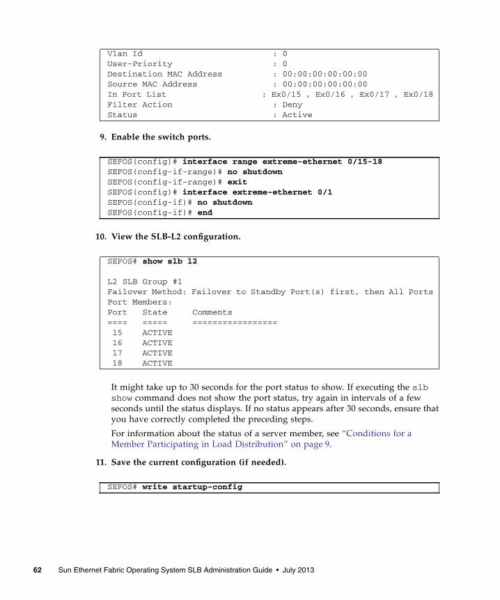
9. Enable the switch ports.
10. View the SLB-L2 configuration.
It might take up to 30 seconds for the port status to show. If executing the slbshow command does not show the port status, try again in intervals of a fewseconds until the status displays. If no status appears after 30 seconds, ensure thatyou have correctly completed the preceding steps.
For information about the status of a server member, see “Conditions for aMember Participating in Load Distribution” on page 9.
11. Save the current configuration (if needed).
Vlan Id : 0User-Priority : 0Destination MAC Address : 00:00:00:00:00:00Source MAC Address : 00:00:00:00:00:00In Port List : Ex0/15 , Ex0/16 , Ex0/17 , Ex0/18Filter Action : DenyStatus : Active
SEFOS(config)# interface range extreme-ethernet 0/15-18SEFOS(config-if-range)# no shutdownSEFOS(config-if-range)# exitSEFOS(config)# interface extreme-ethernet 0/1SEFOS(config-if)# no shutdownSEFOS(config-if)# end
SEFOS# show slb l2
L2 SLB Group #1Failover Method: Failover to Standby Port(s) first, then All PortsPort Members:Port State Comments==== ===== ================= 15 ACTIVE 16 ACTIVE 17 ACTIVE 18 ACTIVE
SEFOS# write startup-config
62 Sun Ethernet Fabric Operating System SLB Administration Guide • July 2013
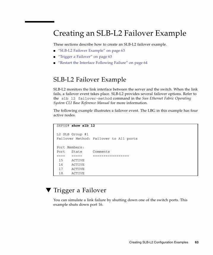
Creating an SLB-L2 Failover ExampleThese sections describe how to create an SLB-L2 failover example.
■ “SLB-L2 Failover Example” on page 63
■ “Trigger a Failover” on page 63
■ “Restart the Interface Following Failure” on page 64
SLB-L2 Failover ExampleSLB-L2 monitors the link interface between the server and the switch. When the linkfails, a failover event takes place. SLB-L2 provides several failover options. Refer tothe slb l2 failover-method command in the Sun Ethernet Fabric OperatingSystem CLI Base Reference Manual for more information.
The following example illustrates a failover event. The LBG in this example has fouractive nodes.
▼ Trigger a FailoverYou can simulate a link failure by shutting down one of the switch ports. Thisexample shuts down port 16.
SEFOS# show slb l2
L2 SLB Group #1Failover Method: Failover to All ports
Port Members:Port State Comments==== ===== ================= 15 ACTIVE 16 ACTIVE 17 ACTIVE 18 ACTIVE
Creating SLB-L2 Configuration Examples 63

1. Shut down a switch port.
2. After a few seconds, examine the SLB-L2 output.
This output shows that port 16 has failed. The port’s state changed from active tofailed. The traffic hashed to the server for port 16 will be rehashed to all remainingactive ports.
▼ Restart the Interface Following FailureWhen the port 16 is repaired and recovered, use the following commands to ensurethat the port status has returned to active.
1. Restart the interface.
SEFOS# configure terminalSEFOS(config)# interface extreme-ethernet 0/16SEFOS(config-if)# shutdownSEFOS(config-if)# end
SEFOS# show slb l2
L2 SLB Group #1Failover Method: Failover to All ports
Members:Port State Comments==== ===== ================= 15 ACTIVE 16 FAILED Failover to All ports 17 ACTIVE 18 ACTIVE
SEFOS# configure terminalSEFOS(config)# interface extreme-ethernet 0/16SEFOS(config-if)# no hutdownSEFOS(config-if)# end
64 Sun Ethernet Fabric Operating System SLB Administration Guide • July 2013
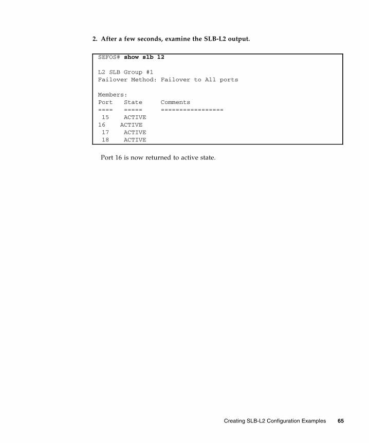
2. After a few seconds, examine the SLB-L2 output.
Port 16 is now returned to active state.
SEFOS# show slb l2
L2 SLB Group #1Failover Method: Failover to All ports
Members:Port State Comments==== ===== ================= 15 ACTIVE16 ACTIVE 17 ACTIVE 18 ACTIVE
Creating SLB-L2 Configuration Examples 65

66 Sun Ethernet Fabric Operating System SLB Administration Guide • July 2013