
Slag Presentation GrafTech 200905
36
Slags in EAF Steelmaking Presented by Stefan Paege, Graftech Switzerland May 2009
-
Upload
lissamariasianipar -
Category
Documents
-
view
64 -
download
4
Transcript of Slag Presentation GrafTech 200905
Slags in EAF Steelmaking
Presented by Stefan Paege, Graftech Switzerland
May 2009

What is Slag?Slags are ionic solutions consisting of molten metal oxides and flourides that float on top of the steel, they can be completely liquid or partially liquid.
Slag in steelmaking is not a necessary evil, to the contrary, it's control is an important part in modern, low-cost, high-quality melting.
"Take care of the slag & the steel will take care of itself."

The Functions of Slag in Electric Steelmaking
- Cover the arcs in the EAF and LF and protect the refractories from arc-flare
- Improve the quality of the steel by absorbing deoxidation products (e.g. SiO2, Al2O3) and inclusions (clean the steel)
- Dephosphorize in the furnace and desulphurize in the ladle
- Protect the metal from oxidation
- Protect the metal from nitrogen and hydrogen absorption
- Insulate the steel to minimize heat loss
- Get a more stable arc and electrical operation, increase efficiency
- Coat the water-cooled roof & shell
- Be fully compatible with the refractory lining

Expected benefits on furnace operation
Shorter tap to tap timesBetter heat transfer to the load & less losses to the w/c panels,
protection of the refractoryHigher average power input
Lower electrode consumptionLower currentsShorter tap to tap times
Cleaner steelRemoval of Nitrogen & Hydrogen due to gas bubbling (CO)Pick up / absorption of Oxides in the slagRemoval of inclusionsPhosphor & Sulphur removal

Efficiency of electric energy transfer with foaming slag
Efficiency = 35% Steel 0% Slag
Efficiency = 90% 100% Slag
Efficiency = 60% 50% Slag

Arc stability & inadequate foaming slag at the end of a heatEven in generally well controlled processes, the foaming quality / height of the slag may become poor at the end of a heat thus influencing the arc stability.
Pictured here in a real EAF electrical examination done by Graftech is the distortion factor D%, that gives a measure of the harmonic content and is therefore an indication of arc stability. As can be seen in this example, due to the decrease in slag foaming quality at the end of the heat, the arc is negatively affected as well.
0
5
10
15
20
25
30
0 5 10 15 20 25 30 35 40 45 50
Minutes
D%
0
200
400
600
800
1000
1200
Volta
ge T
ap

Slag foamingFoaming slag is used to increase the thermal efficiency of the furnace mainly during the refining period, when the side walls otherwise are fully exposed to the arc radiation.
A good foaming slag will cover the electric arcs, thus permitting the use of a high tap setting without increasing the thermal load on the furnace walls. Additionally, the foaming slag cover results in ahigher efficiency of the arc's energy transfer to the bath.
For slag foaming we need
1. A gas (CO that is).
2. Favourable conditions of the slag, usually called "foamability".

The Gas:Depending on the (literature) source, the oxidation of Iron in the bath & the subsequent reduction of the Iron-Oxide in the slag by Carbon according to
O2 + 2 Fe = 2 (FeO) and (FeO) + C = Fe + COgaseous
is considered the main contributing factor for foaming or the direct Oxidation of Carbon in the bath is also taken into account :

Overview of the gas generating reactions in the system
In the Bath At Slag-Metal Interface In The SlagC + O⌫ CO C + FeO ⌫ Fe + CO FeO + C ⌫ Fe + COC +½O2 ⌫ CO 2FeO + C ⌫ 2Fe + CO2
C + ½O2⌫ COC + O2⌫ CO2C + CO2⌫ 2COCaCO3⌫ CaO + CO2MgCO3⌫MgO + CO2
The CO generated in the liquid bath is generally more contributive to good slag foaming than CO formed in the slag itself. This is because the CO coming from the bath consists of small bubbles that are almost uniformly distributed. It also helps to clean the bath.
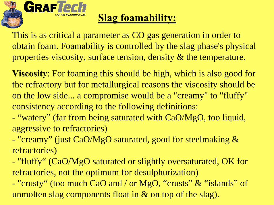
Slag foamability:This is as critical a parameter as CO gas generation in order toobtain foam. Foamability is controlled by the slag phase's physical properties viscosity, surface tension, density & the temperature.
Viscosity: For foaming this should be high, which is also good for the refractory but for metallurgical reasons the viscosity should be on the low side... a compromise would be a "creamy" to "fluffy" consistency according to the following definitions:- “watery” (far from being saturated with CaO/MgO, too liquid, aggressive to refractories)- "creamy” (just CaO/MgO saturated, good for steelmaking & refractories)- "fluffy“ (CaO/MgO saturated or slightly oversaturated, OK for refractories, not the optimum for desulphurization)- "crusty“ (too much CaO and / or MgO, “crusts” & “islands” of unmolten slag components float in & on top of the slag).
Effective Viscosity ( ηe)
Fully Liquid "Creamy" to "fluffy" "Fluffy" to "Crusty"
Liquidus Boundary
(Θ = 0) (Θ > 0)
Optimum Slag
Over-Saturated: Too much second phase particles
Foam
ing
Inde
x (Σ
) [G]
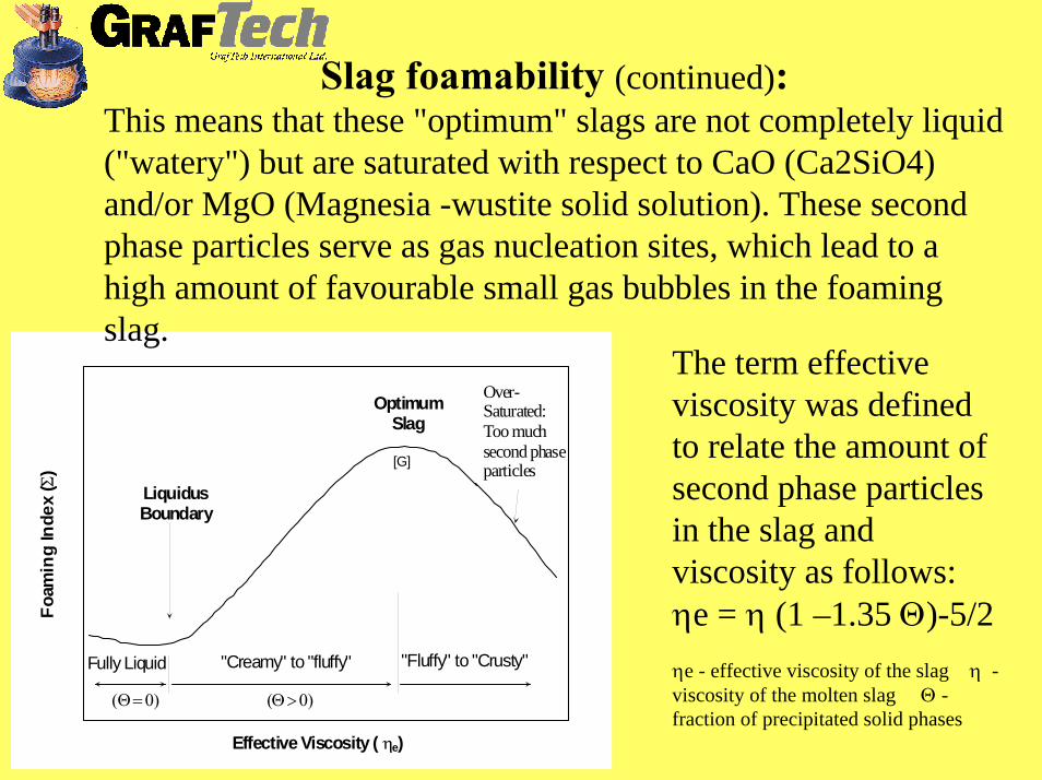
Slag foamability (continued):This means that these "optimum" slags are not completely liquid ("watery") but are saturated with respect to CaO (Ca2SiO4) and/or MgO (Magnesia -wustite solid solution). These second phase particles serve as gas nucleation sites, which lead to a high amount of favourable small gas bubbles in the foaming slag.
The term effective viscosity was defined to relate the amount of second phase particles in the slag and viscosity as follows:ηe = η (1 –1.35 Θ)-5/2ηe - effective viscosity of the slag η -viscosity of the molten slag Θ -fraction of precipitated solid phases
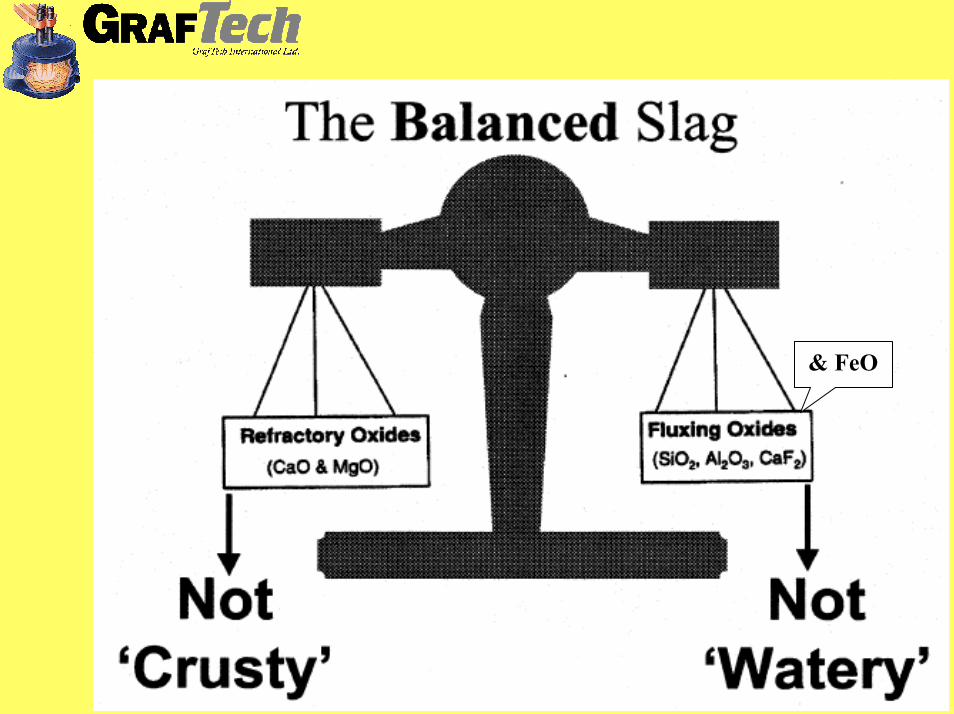
& FeO

Where does the slag come from and how is the slag formed -The building blocks of slag
The composition of a slag is usually expressed in terms of the component oxides (or flourides) on a weight percent basis. For example a slag could have the following composition:
wt% CaO : 32 wt% SiO2 : 15 wt% FeO : 30
wt% MgO : 9 wt% Al2O3 : 5 wt% MnO : 4
wt% CaF2 : 4
Where do these components come from?
CaO - Lime (98 % CaO)
- Dolomite (≈ 58 % CaO & 39 % MgO)
- Ca-Aluminate (≈ 45% CaO & 53% Al2O3)
- Refractories (dolomite)
MgO - Dolomite (≈ 58 % CaO & 39 % MgO)
- Magnesia (> 92% MgO)
- Refractories (Mg-C & Dolomite)

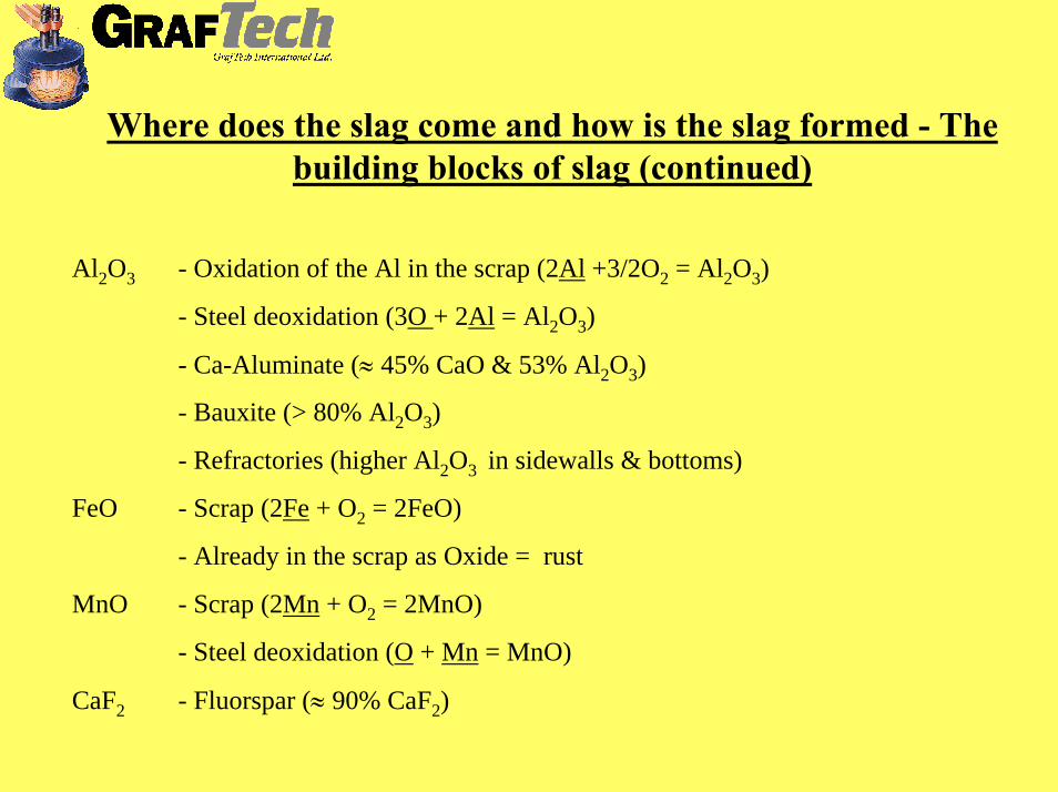
Where does the slag come and how is the slag formed - The building blocks of slag (continued)
SiO2 - Oxidation of the Si in the scrap (Si + O2 = SiO2)
- Steel deoxidation (2O + Si = SiO2)
- Sand and dirt
- RefractoriesMost common steelgrades contain 0,4 - 0,6 % Si, so let's say appr. 5 kg of Si per ton of scrap.1 kg of Si reacts with ~1,15 kg of O2 to form 2,15 kg of SiO2, in our 5kg/t of scrap example that amounts to nearly 11 kg of SiO2 per ton of scrap.So, to achieve our basicity of ~2, we need at least ~22 kg/(t of scrap) of CaO (more if we use scrap with higher amounts of alloyed Si in it).In the case of DRI we will find 2 - 3 % of SiO2 in the DRI pellets / briquets / fines..., so 1 t of DRI contains between 20 - 30 kg of SiO2 & logically we need 40 - 60 kg/(t of DRI) of CaO to achieve our "famous" basicity of "2" - this (& the high amount of slag formation) is also one of the reasons for the "energy penalty" for DRI users in energy calculations.For Pig-Iron, we will typically have Si contents in the 0,8 - 1,2 % range (sometimes higher depending on the ores available), so around 8 - 12 kg/(t of pig-iron) of Si = 17 - 26 kg/(t of pig iron) of SiO2 & we need 34 - 52 kg/(t of pig-iron) of CaO to counteract that.Additionally we will have SiO2 from "non-metallic-dirt" in the scrap, like sand, concrete, bricks or whatever other "filthy substances" we have in our scrapyard.
Where does the slag come and how is the slag formed - The building blocks of slag (continued)
Al2O3 - Oxidation of the Al in the scrap (2Al +3/2O2 = Al2O3)
- Steel deoxidation (3O + 2Al = Al2O3)
- Ca-Aluminate (≈ 45% CaO & 53% Al2O3)
- Bauxite (> 80% Al2O3)
- Refractories (higher Al2O3 in sidewalls & bottoms)
FeO - Scrap (2Fe + O2 = 2FeO)
- Already in the scrap as Oxide = rust
MnO - Scrap (2Mn + O2 = 2MnO)
- Steel deoxidation (O + Mn = MnO)
CaF2 - Fluorspar (≈ 90% CaF2)
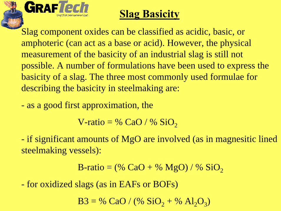
Slag BasicitySlag component oxides can be classified as acidic, basic, or amphoteric (can act as a base or acid). However, the physical measurement of the basicity of an industrial slag is still not possible. A number of formulations have been used to express thebasicity of a slag. The three most commonly used formulae for describing the basicity in steelmaking are:
- as a good first approximation, the
V-ratio = % CaO / % SiO2
- if significant amounts of MgO are involved (as in magnesitic lined steelmaking vessels):
B-ratio = (% CaO + % MgO) / % SiO2
- for oxidized slags (as in EAFs or BOFs)
B3 = % CaO / (% SiO2 + % Al2O3)

SiO2
CaO/SiO2 ≈ 2
Preferred area for EAF slags
FeOCaO
The slag with the right properties can be mainly found in the slag system of FeO-CaO-SiO2
FeO is important for the gas generation. Too small amounts in the slag gives poor gas generation and too much FeO gives a slag that is completely fluid & so impossible to foam. By experience and lab tests the limits are said to be between 10-40 % FeO in the slag.
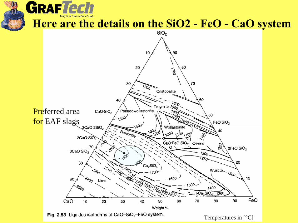
Temperatures in [°C]
Here are the details on the SiO2 - FeO - CaO system
Preferred area for EAF slags
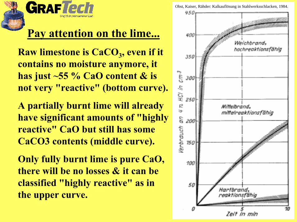
Obst, Kaiser, Rähder: Kalkauflösung in Stahlwerksschlacken, 1984.
Pay attention on the lime...Raw limestone is CaCO3, even if it contains no moisture anymore, it has just ~55 % CaO content & is not very "reactive" (bottom curve).
A partially burnt lime will already have significant amounts of "highly reactive" CaO but still has some CaCO3 contents (middle curve).
Only fully burnt lime is pure CaO, there will be no losses & it can be classified "highly reactive" as in the upper curve.

The Silicate slags that we find in steelmaking have a certain solubility for MgO, hence they attack & consume MgO based refractories that are the standard today in electric arc furnaces.
MgO additions should consider slag basicity at various times during the heat
...UNLESS...
We deliberately add "sacrificial" MgO to the slag.

MgO solubility & it's interdependencesMgO refractories are severly attacked by slags non-saturated in MgO. This saturation limit is slag specific & changes as follows:
Decreases as the basicity of the slag increases.
Decreases as the FeO concentration in the slag increases.
Decreases as the Al2O3concentration in the slag increases.
Increases as the SiO2 concentration in the slag increases.
Increases as the Temperature of the slag increases.

Common ways of adding MgO & the pitfalls
- Dolomite addition:Talking about dolomite, in steelmaking we refer to burnt dolomite = dolomitic lime, typically 58% CaO & 39% MgO. Unfortunately this material is slow to dissolve, additionally depending on it's particle size.This slow dissolution usually results in crusty, poorly foamable "early" slags that still have the potential to attack the refractory & offer no positive coating effects to the EAF panels or roof at all.
- Addition of "used bricks" & other MgO based refractories of ladles & EAF:Certainly, there is MgO in it but the solubility is extremely poor - the manufacturers put quite some effort (binders & chemical bonding) in the production of these bricks to reduce the MgO's dissolution.Using these bricks again to enrich the EAF's slag with MgO is mainly futile, often undissolved bricks just pour out of the furnace through the slag door.Additionally, who has enough "used bricks" to satisfy the appr. 11% MgO necessity in the slag...

Various MgO solution ratesMgO Levels All Runs
0
2
4
6
8
10
12
0 5 10 15 20 25 30 35
Time - Minutes
% M
gO
MgC 1/08
DB MgO 12/07
Dolo 12/07
Dolo 9/07
Std. PS 9/07
source: Carnegie Mellon Institute, USA, 2006

Shell & roof coating by slagThe panels of roof & shell are usually made of steel or even Copper & are watercooled. Both materials are good electrical & heat conductors. Slag on the other hand is an insulator, so the better the slag coating on roof & shell, the lower the energy losses to the cooling water. This coating may also protect from arc & lance flare. Slags with higher MgO levels stick better to the EAF's sidewalls & the roof, thus improve the insulation.
Increasing
(sch
emat
ic)
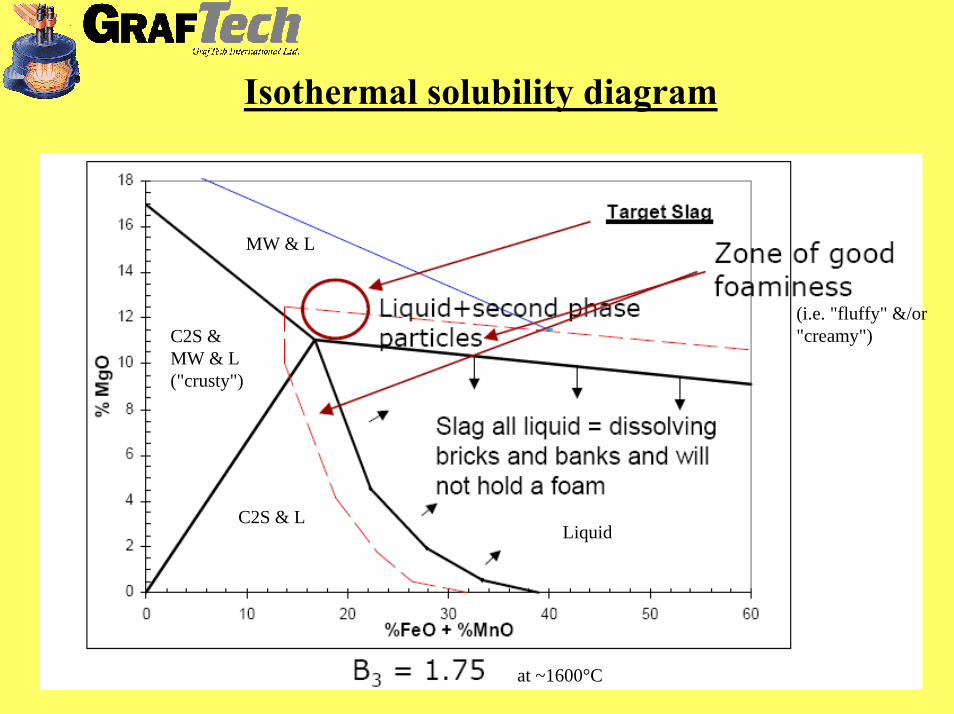
Isothermal solubility diagram
(i.e. "fluffy" &/or "creamy")
MW & L
C2S & MW & L ("crusty")
C2S & LLiquid
at ~1600°C
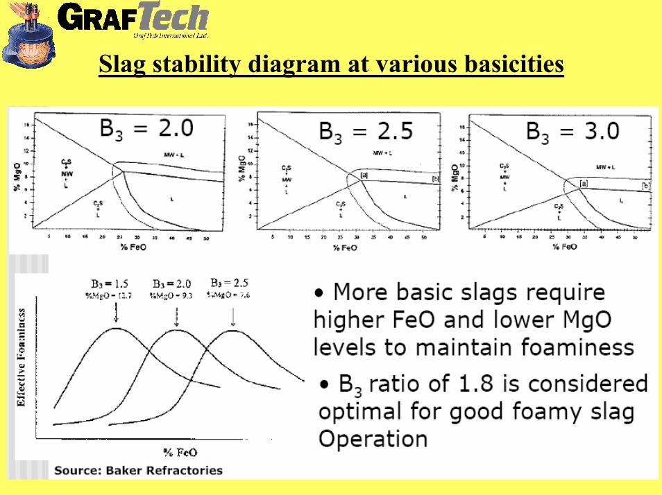
Slag stability diagram at various basicities

The late stages of the heat & effects on slag foaming- Due to the Oxygen injection & the decreasing amount of Carbon & other "burnable" elements (Si, Mn, Al etc.) in the metal bath, the oxidation rate of Fe increases, thereby diluting the slag increasingly with FeO, that being a very fluxing oxide lowers the slag's viscositysignificantly.
- Late in the heat the temperature of the slag is logically quite high, that's another factor lowering the viscosity.
- The carbon content in the bath decreases to very low levels, thus the development of "new" CO is low.
Summarized, we then have a slag of low surface tension, low (to zero) solid, second phase in it & low viscosity - so the foamability is extremely poor & even if we produce "new" CO by blowing Carbon + Oxygen, the retention time of this gas in the slag is so low that we can not foam anymore.
All these factors call for higher MgO content at the end of a heat.
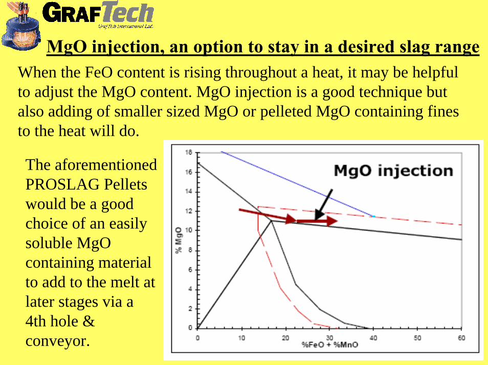
MgO injection, an option to stay in a desired slag rangeWhen the FeO content is rising throughout a heat, it may be helpful to adjust the MgO content. MgO injection is a good technique butalso adding of smaller sized MgO or pelleted MgO containing fines to the heat will do.
The aforementioned PROSLAG Pellets would be a good choice of an easily soluble MgO containing material to add to the melt at later stages via a 4th hole & conveyor.
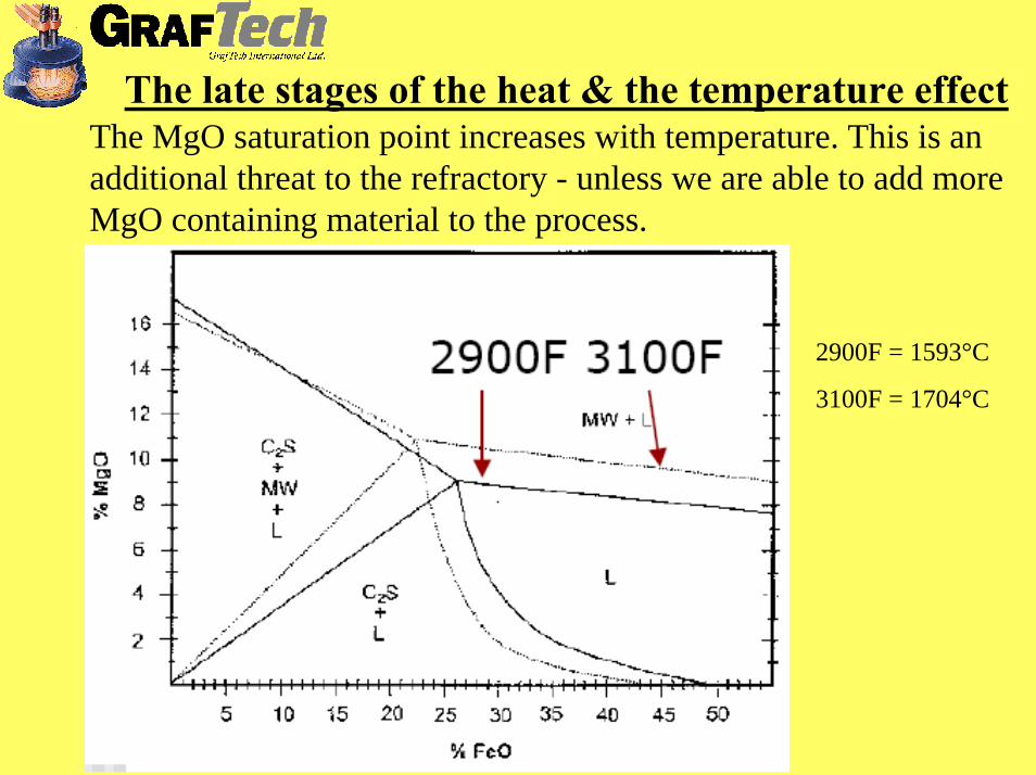
The MgO saturation point increases with temperature. This is an additional threat to the refractory - unless we are able to add more MgO containing material to the process.
The late stages of the heat & the temperature effect
2900F = 1593°C
3100F = 1704°C

Let's summarize:
Why MgO is good for the EAF & the process
- To target for a slag that is always slightly over-saturated (1 - 2 %) with MgO is the easiest way of keeping a favourable viscosity.
- The small, solid MgO particles (or the Magnesiowustite respectively) thicken the slag & act as nuclei for gas bubble formation (this produces the preferred small sized bubbles).
- High MgO slag is easier on refractories.
- Slags with higher MgO levels stick better to the EAF's sidewalls & the roof, thus improve the insulation.

Is favoured by:- High basicity.- High FeO content (below 15% FeO it's barely possible to remove P). - "Low" temperature (in the range of 1560 - 1580°C).
Phosphorous removal
P distribution = %P in slag compared to the total P, so e.g. 40 means 40% of the P in the slag, 60% in the steel.

Phosphorous removal A good slag chemistry for Phosphorous removal is:- %CaO / %SiO2 > 2- FeO between 25% to 30%To avoid re-Phosphorization with increasing temperature, a slag-exchange may be necessary
2800F = 1538°C
2900F = 1593°C
3000F = 1649°C

The relevant Desulphurization reaction is [FeS] + (CaO) + [C] = (CaS) + [Fe] + {CO}... + ∆H
It is favoured by:- High basicity.- High Temperature (it's an endothermic reaction).- Low FeO content (< 3% - 4%).- Large contact surfaces between metal bath & slag.- Large slag amounts or even slag changes.
EAF slag does not provide EFFICIENT Sulphur removal mainly due to the high FeO content.
Sulphur removal

If steel contains dissolved Oxygen (& it always does in the EAF...), Nitrogen will not enter in molecular form (N2) but it can do so in atomic form.
Nitrogen pick-up prevention
High temperature in the arc zone causes N2cracking, so that atomic Nitrogen can then penetrate the steel bath.The better the arc is covered by foamy slag, the lower that Nitrogen "atomization" & pick-up.

Nitrogen removal in the EAF
Thanks for the attention and remember: Take care of your
slag & the steel will take care of itself...


![[XLS] 1a... · Web viewShruti VIG N/C/200905/159 Gaurav bansal W/C/200905/160 Atul M. Mehta N/C/200905/161 Kamla Devi N/C/200905/162 Dinesh Kumar W/C/200905/163 Vishal Tiwari, 406/2009](https://static.fdocuments.in/doc/165x107/5aba5c507f8b9ad1768b6a1c/xls-1aweb-viewshruti-vig-nc200905159-gaurav-bansal-wc200905160-atul-m.jpg)


![[XLS] 1a... · Web viewVikas Tiwari N/C/200905/15 Vijendra Singh Chaudhary N/C/200905/16 Dalwinder Kaur Shah N/C/200905/17 Ashish Maskara IIa W/C/200910/215 S. R. Kukreja S/C/200910/216](https://static.fdocuments.in/doc/165x107/5ab776317f8b9ac1058b7473/xls-1aweb-viewvikas-tiwari-nc20090515-vijendra-singh-chaudhary-nc20090516.jpg)