SLAG ANALYSIS SOLUTIONS - Bruker · PDF fileTotal time from sampling to result < 15 min! ......
63
Slag Analysis by X-ray Fluorescence Spectrometry
Transcript of SLAG ANALYSIS SOLUTIONS - Bruker · PDF fileTotal time from sampling to result < 15 min! ......

Slag Analysis byX-ray Fluorescence
Spectrometry

Welcome
Today’s topics• Why analyze slag?
o EAF furnaceo How slag is formedo Foaming o Modeling
• Slag Analysiso XRF fundamentalso Instrumentation
• Summary• Q & A
Arkady BumanXRF Technical Sales SpecialistBruker AXS Inc.Madison, WI, USA

Today’s Panelists
Alexander SeyfarthProduct Manager, XRF Bruker AXS Inc.Madison, WI, USA
Dan PecardService & Applications Engineer, XRFBruker AXS Inc.Madison, WI, USA
Why Analyze Slag?
Alexander Seyfarth
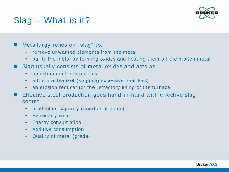
Slag – What is it?
Metallurgy relies on “slag” to:• remove unwanted elements from the metal • purify the metal by forming oxides and floating them off the molten metal
Slag usually consists of metal oxides and acts as• a destination for impurities• a thermal blanket (stopping excessive heat loss) • an erosion reducer for the refractory lining of the furnace
Effective steel production goes hand-in-hand with effective slag control• production capacity (number of heats)• Refractory wear• Energy consumption• Additive consumption• Quality of metal (grade)

The EAF furnace
“Standard furnace” for Mini-Mill production of steel as pioneered by NUCOR (see also Wikipedia - EAF)
(PD) Wikipedia Image

Slag Line Brick “Hot Spot” Brick Pad
EBT Tap Hole Assemblies
Monolithic Materials
for New Installations and Repairs
MgO Safety Brick
Lower Wall Brick
High-tech refractory

Courtesy of BAKER Refractories
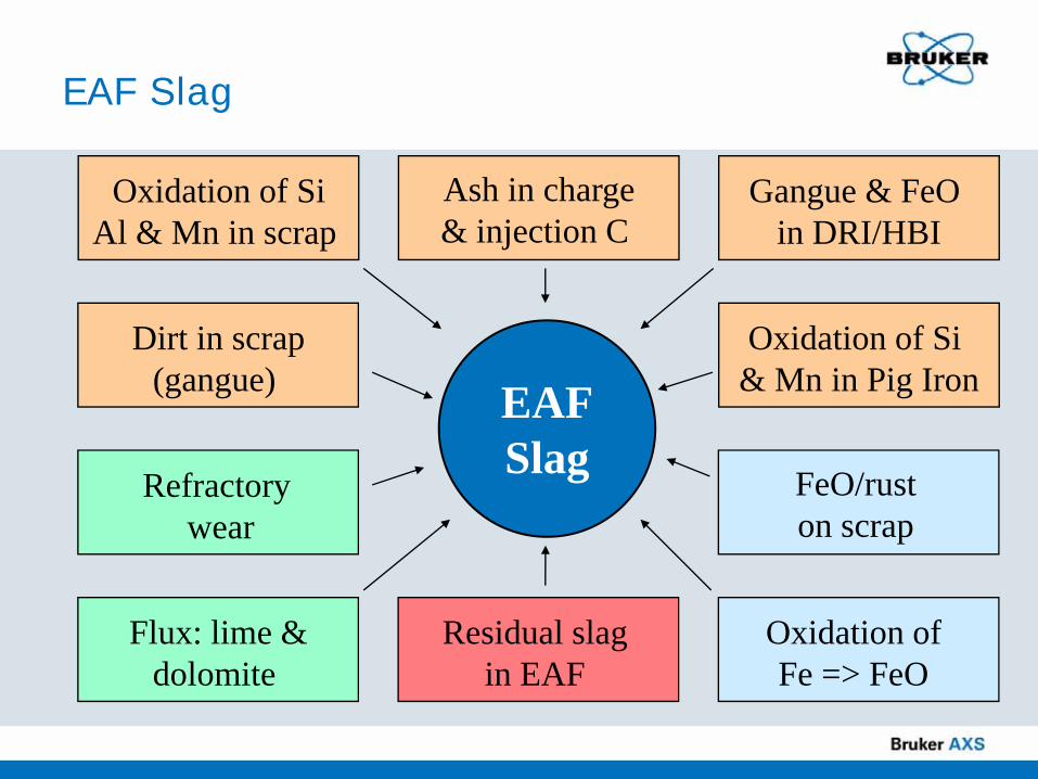
EAF Slag
Flux: lime &dolomite
Refractory wear
Oxidation of Fe => FeO
FeO/rust on scrap
Residual slag in EAF
Oxidation of Si & Mn in Pig Iron
Ash in charge& injection C
Gangue & FeO in DRI/HBI
Dirt in scrap(gangue)
Oxidation of SiAl & Mn in scrap
EAFSlag
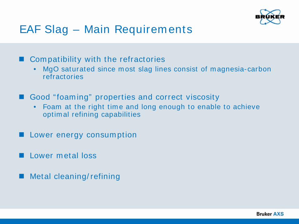
EAF Slag – Main Requirements
Compatibility with the refractories• MgO saturated since most slag lines consist of magnesia-carbon
refractories
Good “foaming” properties and correct viscosity• Foam at the right time and long enough to enable to achieve
optimal refining capabilities
Lower energy consumption
Lower metal loss
Metal cleaning/refining

Raw Materials
High Calcium Lime (Ca source)Dolomitic Lime (Ca, Mg source)Pre-blended Lime Mixes (Met Grade) Ca Mg mixMgO – Carbon Briquettes (Proslag™) (Mg and C source)Pig iron – Fe, Mn to counter high Ni, Cu, Cr scrap

EAF slag composition –analytical requirements
% MgO 8% CaO 43% FeO 26% MnO 6% Al2O3 4% SiO2 13
Fluxing Oxides
Refractory Oxides

Slag formation in the EAF – meltdown
Slag formers are either charged with the scrap or blown into the furnace.
The Si and Al in the scrap are oxidized first to form SiO2 and Al2O3 (fluxing oxides).
As oxygen is blown into the furnace, the principal flux (FeO) is generated.
The "slag balance" now starts to shift and the slag becomes more liquid.

Carbon and additive injection
Courtesy Carmeuse Technical Training
Slag

Slag Formation in the EAF –flat bath and then hitting the spot
Carbon (in the form of coke or coal) is lanced into the slag layer, partially combusting to form carbon monoxide gasThis causes the slag to foam • achieving greater thermal efficiency• better arc stability • better electrical efficiency
The slag blanket also covers the arcs, preventing damage to the furnace roof and sidewalls from radiant heat.

Slag formation in the EAFEf
fect
ive
foam
ines
s/vi
scos
ity
Time(Amount of FeO generated)
Too Crusty
Too Liquid
Optimum Foaming
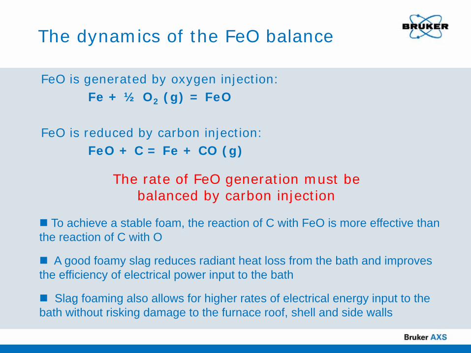
The dynamics of the FeO balance
FeO is generated by oxygen injection:Fe + ½ O2 (g) = FeO
FeO is reduced by carbon injection:FeO + C = Fe + CO (g)
The rate of FeO generation must be balanced by carbon injection
.
To achieve a stable foam, the reaction of C with FeO is more effective than the reaction of C with O
A good foamy slag reduces radiant heat loss from the bath and improves the efficiency of electrical power input to the bath
Slag foaming also allows for higher rates of electrical energy input to the bath without risking damage to the furnace roof, shell and side walls

Slag variables and impact on viscosity
FeO content (fluxing component)• Increasing the FeO decreases slag viscosity
MgO content (refractory component)• Increasing the MgO increases slag viscosity
Temperature• Increasing temperature decreases viscosity
Slag basicity• Slag basicity controls the timing and the extent of foaming
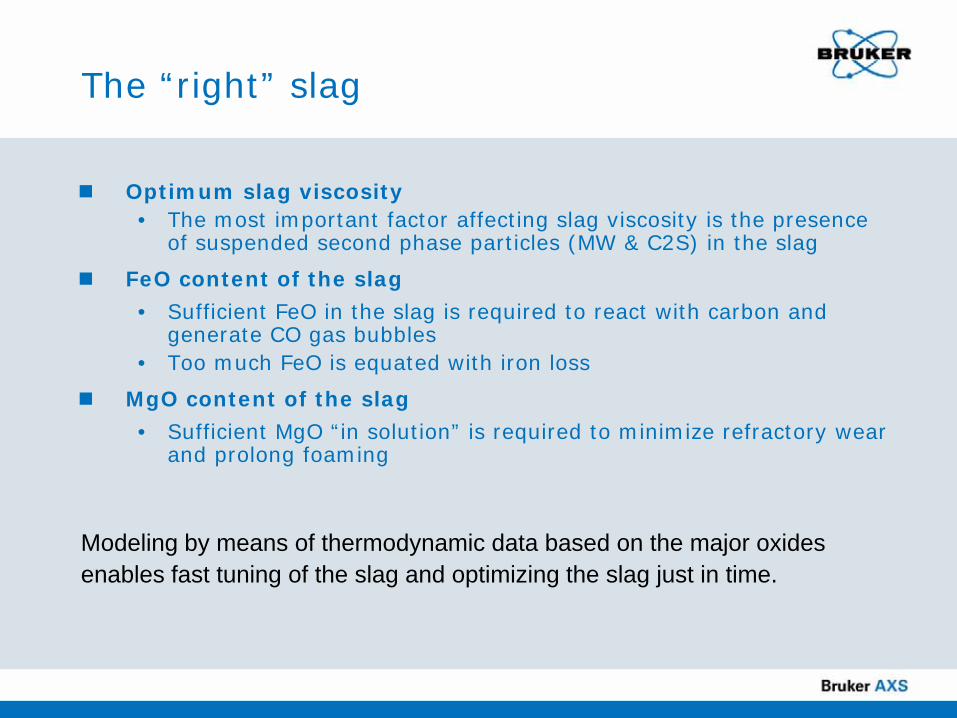
The “right” slag
Optimum slag viscosity• The most important factor affecting slag viscosity is the presence
of suspended second phase particles (MW & C2S) in the slag
FeO content of the slag
• Sufficient FeO in the slag is required to react with carbon and generate CO gas bubbles
• Too much FeO is equated with iron loss
MgO content of the slag
• Sufficient MgO “in solution” is required to minimize refractory wear and prolong foaming
Modeling by means of thermodynamic data based on the major oxides enables fast tuning of the slag and optimizing the slag just in time.
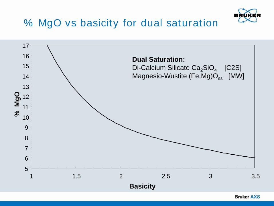
% MgO vs basicity for dual saturation
Dual Saturation:Di-Calcium Silicate Ca2SiO4 [C2S]Magnesio-Wustite (Fe,Mg)Oss [MW]
5
67
8
910
11
1213
14
1516
17
1 1.5 2 2.5 3 3.5
Basicity
% M
gO
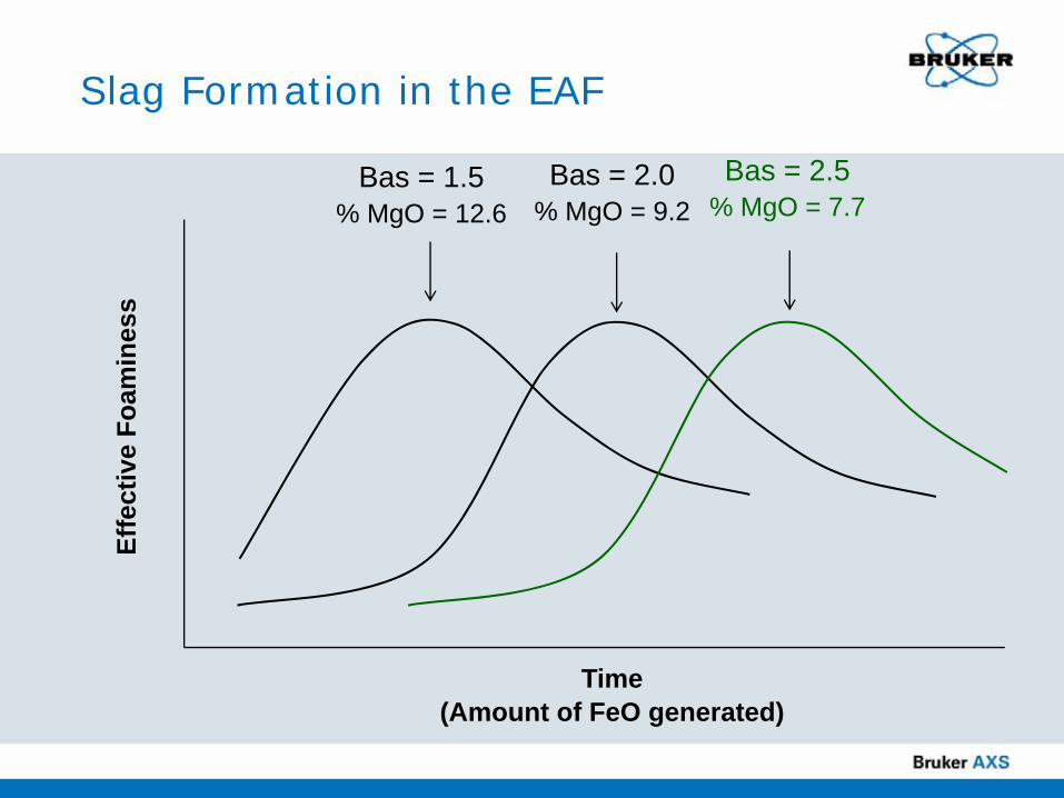
Slag Formation in the EAFEf
fect
ive
Foam
ines
s
Time(Amount of FeO generated)
Bas = 1.5% MgO = 12.6
Bas = 2.0% MgO = 9.2
Bas = 2.5% MgO = 7.7
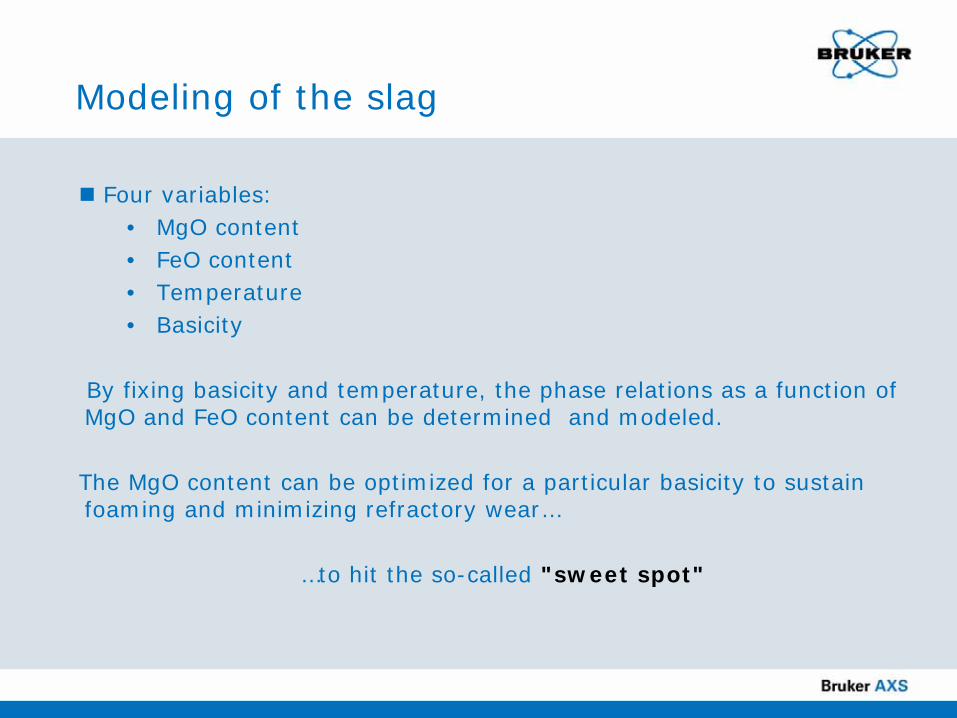
Modeling of the slag
Four variables:• MgO content• FeO content• Temperature• Basicity
By fixing basicity and temperature, the phase relations as a function of MgO and FeO content can be determined and modeled.
The MgO content can be optimized for a particular basicity to sustain foaming and minimizing refractory wear…
…to hit the so-called "sweet spot"
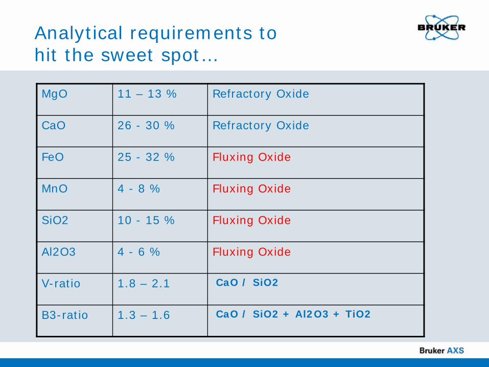
Analytical requirements to hit the sweet spot…
MgO 11 – 13 % Refractory Oxide
CaO 26 - 30 % Refractory Oxide
FeO 25 - 32 % Fluxing Oxide
MnO 4 - 8 % Fluxing Oxide
SiO2 10 - 15 % Fluxing Oxide
Al2O3 4 - 6 % Fluxing Oxide
V-ratio 1.8 – 2.1 CaO / SiO2
B3-ratio 1.3 – 1.6 CaO / SiO2 + Al2O3 + TiO2
Factors for slag analysis
Increase the life of the furnaceReduce energy consumptionReduce the amount of additives neededImprove the quality of steel
In order to maximize steel production, it is critical to effectively control the slag condition in the furnace.
One of the most important tools for slag control is the fast, reliable slag analyzer, which allow quick and reproducible analysis of all the oxides in the slag.
Factors for slag analysis
Total time from sampling to result < 15 min!• Get the data while heat is still on!
Repeatable and fit-for-purpose results • Accuracy for Mg and Al, Si important• Ratios to be calculated with analysis (B3 and V or more)
Modeling compliant data
Rugged system: to be close to the EAF
Easy to use
Introduction to XRFand Slag Analysis
Dan Pecard

Please use your mouse to answer the question on your screen:
What method(s) do you currently use to analyze slag? Check all that apply:
NoneExternal lab (non-routine)XRF – energy-dispersive XRF – wavelength-dispersiveOES Other
Audience Poll

X-ray Fluorescence AnalysisEnergy Dispersive XRF (EDXRF)
Energy of X-ray photons:• element • qualitative analysis
Number of X-ray photons at a given energy: • concentration • quantitative analysis
Sample

X-ray Fluorescence AnalysisWavelength Dispersive XRF (WDXRF)
An analyzer crystal separates the various wavelengths. λ (energies)
The detector records only the number. N. of X-ray photons at a given wavelength (energy)
Sample
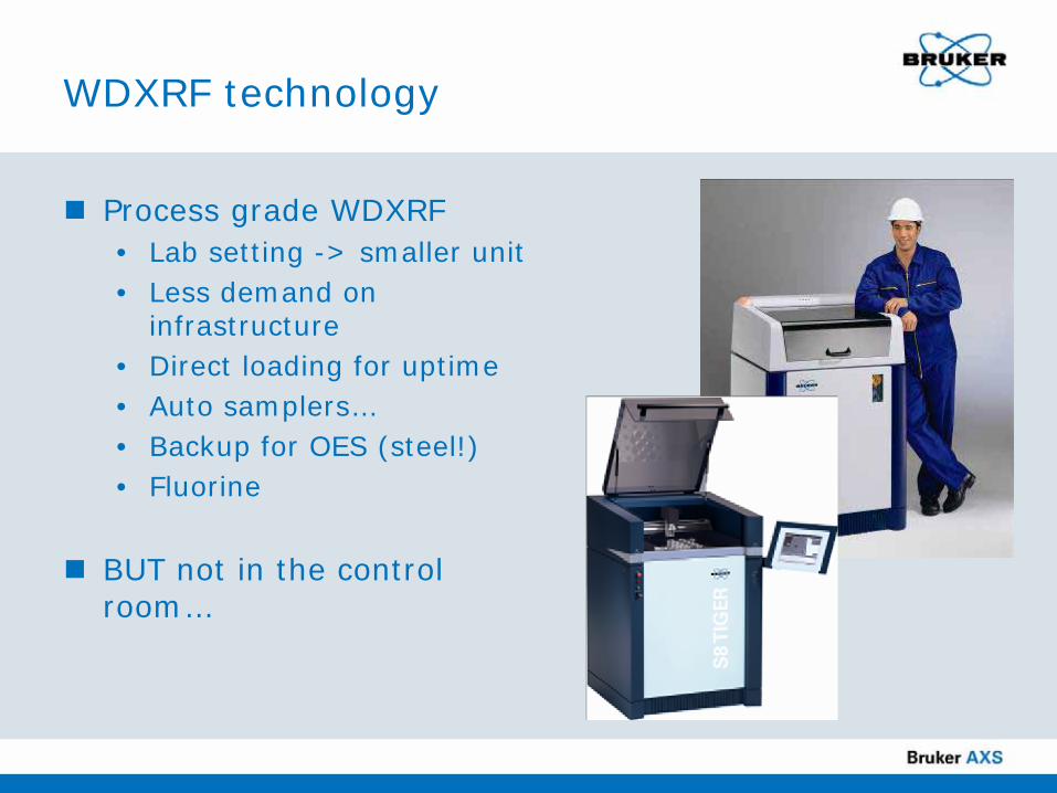
WDXRF technology
Process grade WDXRF• Lab setting -> smaller unit • Less demand on
infrastructure• Direct loading for uptime• Auto samplers…• Backup for OES (steel!)• Fluorine
BUT not in the control room…
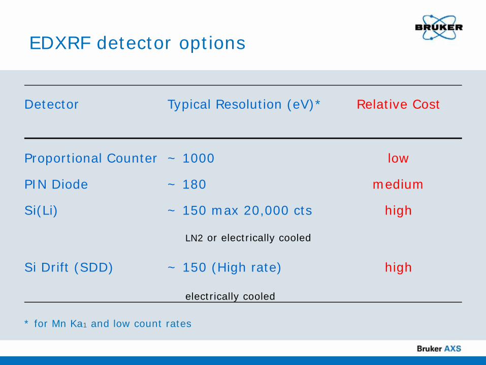
EDXRF detector options
Detector Typical Resolution (eV)* Relative Cost
Proportional Counter ~ 1000 low
PIN Diode ~ 180 medium
Si(Li) ~ 150 max 20,000 cts high
LN2 or electrically cooled
Si Drift (SDD) ~ 150 (High rate) high
electrically cooled
* for Mn Ka1 and low count rates

Standard detector vs Bruker XFlash® 410
Energy resolution of Cu Kα at different count rates

Peak separation and element sensitivity at 100,000 cps
Si
AlMg

Sample Preparation

Sample taken manually or by robot
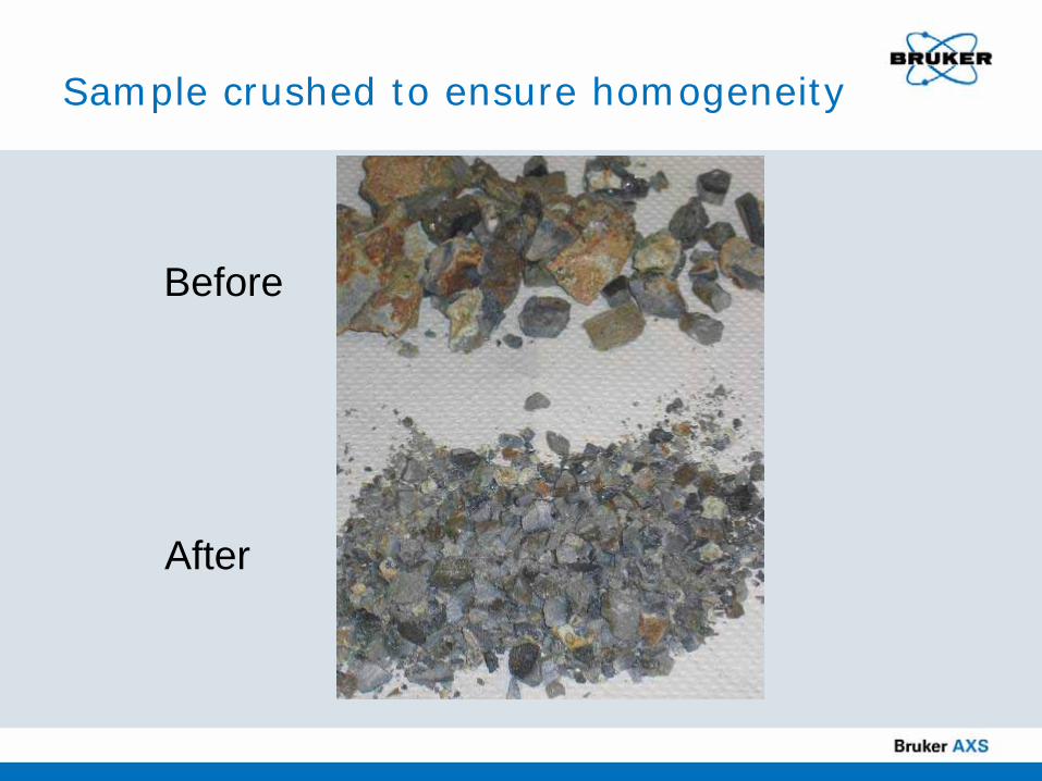
Sample crushed to ensure homogeneity
Before
After
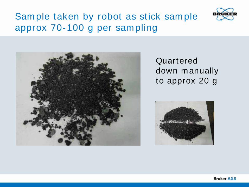
Sample taken by robot as stick sample approx 70-100 g per sampling
Quartered down manually to approx 20 g

Sample Preparation: Dose – Grind – Press
Crush sampleGrind sample Press powder into tablet

Remove “iron” from powder

Please use your mouse to answer the question on your screen:
How do you most frequently prepare your samples?
NoneLoose powderPressed pellet FusionGraphite for OESOther
Audience Poll

Bruker SLAG QUANTThe solution for the mill!
LMF, EAF analysis conditions and methodsEAF calibration from international reference samplesTuned with local samplesDrift correction sample (monitor) - special stable conditioned glassV and B3 ratio calculation included SOP and QA/QC to use in customer QA/QC system
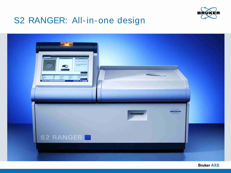
S2 RANGER: All-in-one design
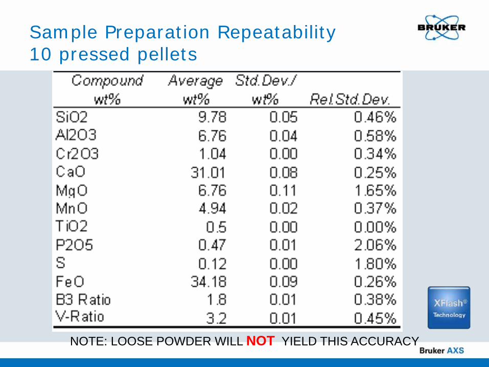
Sample Preparation Repeatability10 pressed pellets
NOTE: LOOSE POWDER WILL NOT YIELD THIS ACCURACY
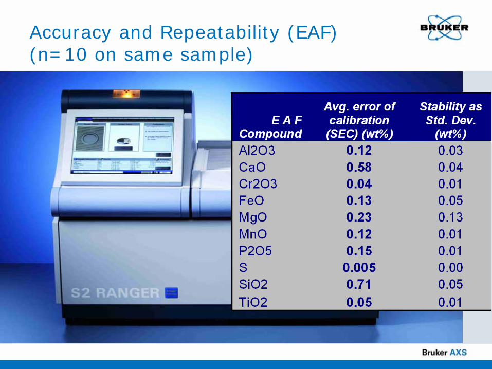
Accuracy and Repeatability (EAF) (n=10 on same sample)

Long term stability…S2 RANGER with XFlash™
Glass sample using EAF calibration on a lab system
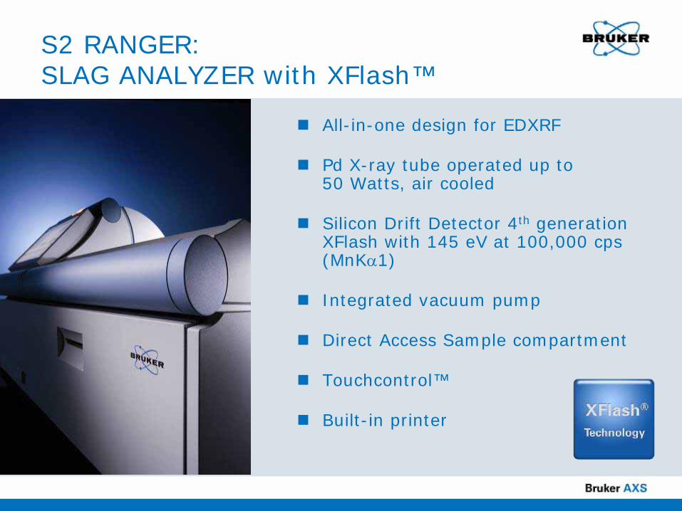
S2 RANGER: SLAG ANALYZER with XFlash™
All-in-one design for EDXRF
Pd X-ray tube operated up to 50 Watts, air cooled
Silicon Drift Detector 4th generation XFlash with 145 eV at 100,000 cps (MnKα1)
Integrated vacuum pump
Direct Access Sample compartment
Touchcontrol™
Built-in printer
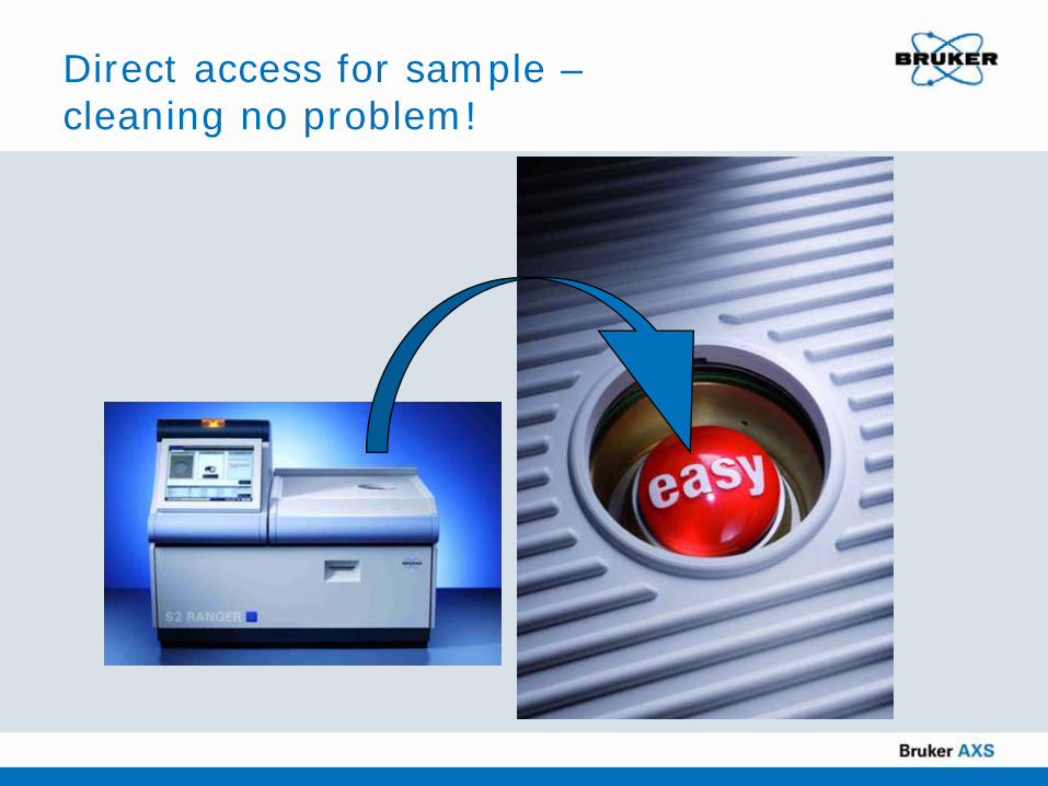
Direct access for sample –cleaning no problem!

Touchcontrol™Select application: EAF or LMF

Touchcontrol™Type in sample ID: heat number

Touchcontrol™Measure sample

Touchcontrol™Wait 3-4 minutes

Touchcontrol™Get results
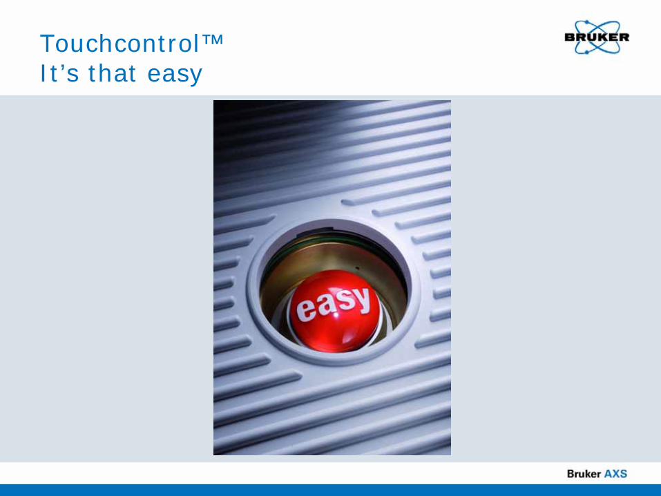
Touchcontrol™It’s that easy

Connectivity...Networked via TCP/IP
On Demand via WebEx

S2 RANGER SLAGANALYZER
Total time from sample prep to results: < 15 min
Repeatable and fit-for-purpose results
Easy to use
Results transmittable to Level 2
Rugged all-in-one design
What does all this mean to you?
The S2 RANGER SLAGANALYZER is the ideal analyzer to establish slag analysis in your plant
It’s the right tool for the metallurgist and the operators • No compromises• Fast quantification with accurate results
The S2 RANGER SLAGANALYZER enables the implementation of the foamy slag model, as well as optimized operation with specialized additives such as Proslag™.
Developed in cooperation with NUCOR steel
Fielded in North America with over 20 installations
X-ray spectrometry solution scalable to your plant’s needs

Summary
Arkady Buman

Why slag analysis?
New furnace refractory linings enable more heats between maintenance intervals• e.g. dry monolithic bottom material instead of brick• Specialized zone-based lining with customized bricks
Slag is used to protect refractory material• Less repair and downtime• More heats in combination with refractory optimization
Slag properties impact energy consumptionControl of additives to create effective slag • Additives for Mg and Ca • Additives for C• Additives for Al, Si flux
Slag optimization for better alloy quality
XRF Slag Analyzer from Bruker
Dedicated instrument right in the melt shop
Pre-calibrated and easy to use
Fast and reliable analysis
Small, rugged benchtop unit
Results are transmitted to control room/Level 2

Payback of slag control
Use of monolithic patching material decreased from 7.0 to 5.5 lb per ton of steel producedGunning material consumption decreased from 2.4 to 0.7 lb per tonFurnace brick life doubledEnergy consumption per heat decreased from 339 to 323 kW/tonTons per hour increased from 113 to 119.5
With the right slag control this would have been your PAYBACK
Thank you for attending!
Please type any questions you may have in the Q&A panel.
Copies of this presentation and related XRF resource materials will be
emailed to you.

www.bruker-axs.com
Visit us at:
Canadian Mineral Analysts (CMA)Bathurst, New Brunswick, Sep 15-19
MINExpo InternationalLas Vegas, Nevada, Sep 22-24
Material Science & Technology (MS&T)Pittsburgh, Pennsylvania, Oct 5-9
XRF for YOU SeminarDenver, Colorado, Oct 10
www.bruker-axs.com