SLACnet - Implementation and Experiences. * -6
43
SLAC - PUB - 3894 March 1986 (Ml .- SLACnet - Implementation and Experiences. * - -6 R. L. A. Cottrell, T. Downey, H. Frese, C. Granieri, M. Huffer, L. Moss, T. Streater, 0. Saxton, D. Wiser. . Stanford Linear Accelerator Center Stanford University, Stanford, California, 94305 Presented at the SHARE 66 Conference, Anaheim, California, March 16-21, 1986. SHARE Installation Code: SLA Sponsoring Projects: VM System Interface, Local Area Networks. Session Number: C403/0672 * Work Supported by the Department of Energy, contract DE - AC03 - 76SF00515.
Transcript of SLACnet - Implementation and Experiences. * -6
SLAC - PUB - 3894 March 1986 (Ml
.-
SLACnet - Implementation and Experiences. * - -6
R. L. A. Cottrell, T. Downey, H. Frese, C. Granieri, M. Huffer, L. Moss, T. Streater, 0. Saxton, D. Wiser. .
Stanford Linear Accelerator Center Stanford University, Stanford, California, 94305
Presented at the SHARE 66 Conference, Anaheim, California, March 16-21, 1986.
SHARE Installation Code: SLA Sponsoring Projects: VM System Interface, Local Area Networks. Session Number: C403/0672
* Work Supported by the Department of Energy, contract DE - AC03 - 76SF00515.
ABSTRACT
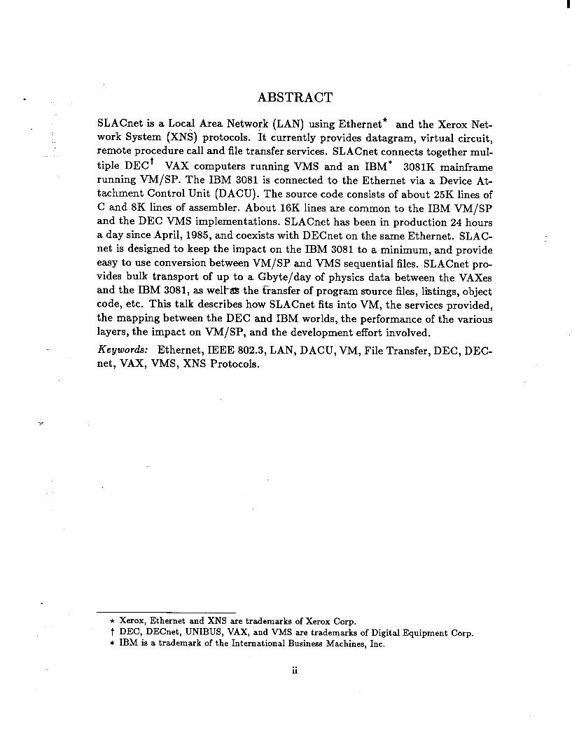
SLACnet is a Local Area Network (LAN) using Ethernet* and the Xerox Net- work System (XNS) protocols. It currently provides datagram, virtual circuit, remote procedure call and file transfer services. SLACnet connects together mul- tiple DECt VAX computers running VMS and an IBM* 3081K mainframe running VM/SP. The IBM 3081 is connected to the Ethernet via a Device At- tachment Control Unit (DACU). Th e source code consists of about 25K lines of C and 8K lines of assembler. About 16K lines are common to the IBM VM/SP and the DEC VMS implementations. SLACnet has been in production 24 hours a day since April, 1985, and coexists with DECnet on the same Ethernet. SLAC- net is designed to keep the impact on the IBM 3081 to a minimum, and provide easy to use conversion between VM/SP and VMS sequential files. SLACnet pro- vides bulk transport of up to a Gbyte/day of physics data between the VAXes and the IBM 3081, as well% the transfer of program source files, listings, object code, etc. This talk describes how SLACnet fits into VM, the services provided, the mapping between the DEC and IBM worlds, the performance of the various layers, the impact on VM/SP, and the development effort involved.
Keywords: Ethernet, IEEE 802.3, LAN, DACU, VM, File Transfer, DEC, DEC- net, VAX, VMS, XNS Protocols.
* Xerox, Ethernet and XNS are trademarks of Xerox Corp. t DEC, DECnet, UNIBUS, VAX, and VMS are trademarks of Digital Equipment Corp. * IBM is a trademark of the International Business Machines, Inc.
ii
Table of Contents 1. Introduction ......................... 1 2. Environment ..... f ................... 1 3.Goals ............................ 4
3.1 User Goals ....................... 4 3.2 Implementer Goals .................... 5
4. Protocols Layering ...................... 5 4.1 Physical Layer ..................... 6 4.2 Link Layer ....................... 7 4.3 Network and Transport Layers .............. 7
4.3.1 Network Layer ................... 7 4.3.2 Transport Layer .................. 7
4.4 Session Layer ...................... 9 4.5 Presentation Layer .................... 9
4.5.1 CouriersmoteProcedure Call Protocol .. -1 .... 9 4.5.2 Bulk Data Transfer Protocol ............. 9
4.6 Application Layer .................... 10 4.7 User Interface ..................... 11
4.7.1 VMS Examples ................... 12 4.7.2 VM/SP Examples ................. 13
5. VM/SP Implementation .................... 13 5.1 Network Communication Executive (NCX) ......... 14 5.2 Link Layer ...................... 14 5.3 Network and Transport Layers .............. 15 5.4 Session, Presentation and Application Layers ........ 16
5.4.1 Master End .................... 16 5.4.2 Opening the Session ................ 17 5.4.3 Slave End .................... 17
5.5 Error Messages .................... 18 5.6 VM/SP Disk I/O Package (ioPack) ............ 18 5.7 LINK Passwords ..................... 19 5.8 VM Synchronization ................... 19
6. Performance ........................ 19 6.1 VMS ......................... 19 6.2 VM ......................... 20
6.2.1 Link Layer ..................... 20 6.2.2 Transport Layer .................. 20 6.2.3 File Transfer Layer ................. 21
6.2.3.1 File Transfer Rates (Disk to Disk) ...... 21 6.2.3.2 CPU Impact on IBM 3033: ......... 22
. . . 111

7.Code ........................... 23 7.1 Source Code ..................... 23 7.2 Object Code ...................... 25
7.2.1 ITP ....................... 25 7.2.2 Listener ..................... 25 7.2.3 File Transfer Layer ................. 25
8. Statistics Gathering and Accounting .............. 26 8.1 Accounting ....................... 26 8.2 Network Management .................. 26
8.2.1 Real Time Monitoring ................ 26 8.2.2 Probing the Network ................ 26
9. Discussion ......................... 27 9.1 Choices ....................... 27 9.2 Differences between the VMS and VM Environments ..... 27 9.3 Performance-“. . T ........ : .......... 28
10. Acknowledgements ..................... 28 A. Appendix: Details on the Use of the DACU ........... 29
A.1 Subchannel 4, Control .................. 29 A.2 Subchannel 5, Buffered Write ............... 29 A.3 Subchannel 6, Buffered Read ............... 30
B. Appendix: Client Interfaces .................. 31 B.l Network Layer .................... 31 B.2 Transport Layer ..................... 31 B.3 Courier Remote Procedure Call .............. 33 B.4 Bulk Data Transfer ................... 35 B.5 Disk I/O Package .................... 36
B.5.1 CMS Minidisk Support ............... 36 B.5.2 Spool Support ................... 36
iv

1. Introduction
This talk will discuss the design, functionality, implementation and experiences in developing a way to provide medium speed (tens of kilobytes/second) file transfer service between DEC VAXes and IBM mainframes. Besides describing how it was done, I will also mention some of the choices we faced, the issues raised by the developing in and connecting of two dissimilar operating and file systems, and the factors that had to be taken into account to get reasonable performance. Most of the emphasis will be from the VM/SP point of view, since this is where most of the effort was expended. The description will be in terms of the International Standards Organization’s (ISO) proposed Reference Model for Open System Interconnection (OSI)!a61
2. Environment
The Stanford Linear Accelerator Center (SLAC) is a national laboratory, funded by the DOE and run by Stanford University. It is one of the leading centers world-wide for basic research in elementary particle physics. There are about 1200 SLAC employees and about 200 visitors from universities and laboratories of 40 different nations.
On site, SLAC has around 27 DEC VAX computers running VMS which are con- nected together by DECnet, and used for real time, online equipment monitoring and control, data acquisition, analysis, display, and logging. The data files can be transferred by 6250bpi tapes and by SLACnet to the computer center, which has an IBM 3081K mainframe and an IBM 3033 mainframe both running VM/SP. A typical amount of data transferred would be around 600 Mbytes/day. The tapes are kept in a large tape library currently holding about 50000 tapes. The IBM mainframes are used to run detailed off-line analysis FORTRAN programs to perform: sophisticated pattern recognition techniques to recognize points in space; reconstruction of particle tracks through the points; extensive statistical analysis and summarizing; and presentation of the data in both graphical and tabular formats. The mainframes also support interactive program development, text entry and document preparation, experiment design and modelling as well as more down-to-earth things like payroll preparation.
1
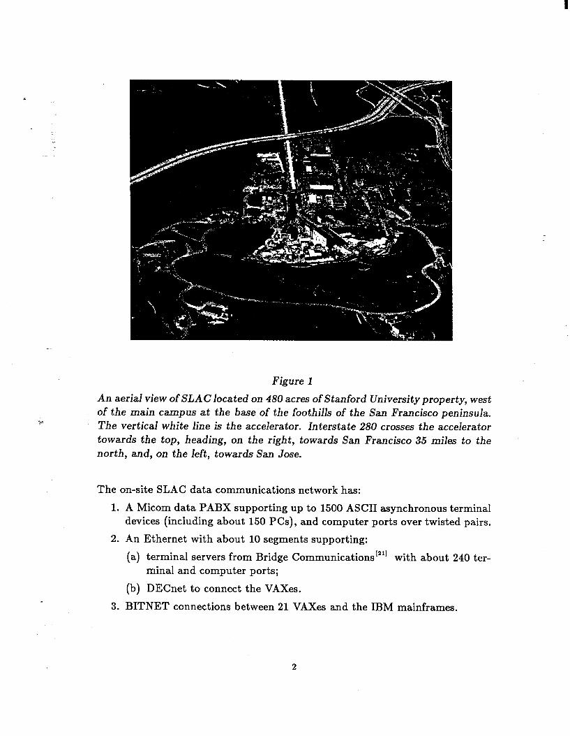
Figure 1
An aerial view of SLAC located on 480 acres of Stanford University property, west of the main campus at the base of the foothills of the San Francisco peninsula. The vertical white line is the accelerator. Interstate 280 crosses the accelerator towards the top, heading, on the right, towards San Francisco 35 miles to the north, and, on the left, towards San Jose.
The on-site SLAC data communications network has:
1. A Micom data PABX supporting up to 1500 ASCII asynchronous terminal devices (including about 150 PCs), and computer ports over twisted pairs.
2. An Ethernet with about 10 segments supporting:
(a) terminal servers from Bridge Communications’“’ with about 240 ter- minal and computer ports;
(b) DECnet to connect the VAXes.
3. BITNET connections between 21 VAXes and the IBM mainframes.
2
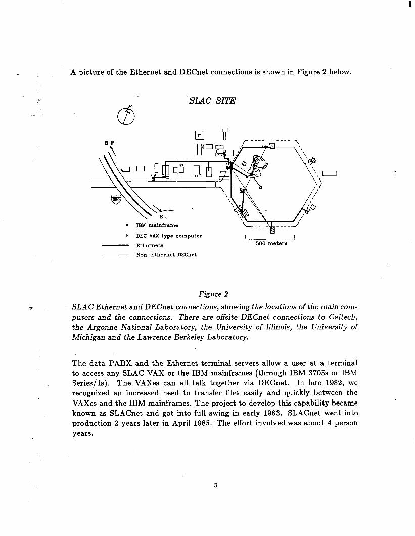
A picture of the Ethernet and DECnet connections is shown in Figure 2 below.
'SLAC SITE N 69
. IBM mainframe
0 DEC VAX type computer I I Ethernets 500 meters
Non-Ethernet DECnet
Figure 2
SLAC Ethernet and DECnet connections, showing the locations of the main com- puters and the connections. There are offsite DECnet connections to Caltech, the Argonne National Laboratory, the University of Illinois, the University of Michigan and the Lawrence Berkeley Laboratory.
The data PABX and the Ethernet terminal servers allow a user at a terminal to access any SLAC VAX or the IBM mainframes (through IBM 3705s or IBM Series/is). The VAXes can all talk together via DECnet. In late 1982, we recognized an increased need to transfer files easily and quickly between the VAXes and the IBM mainframes. The project to develop this capability became known as SLACnet and got into full swing in early 1983. SLACnet went into production 2 years later in April 1985. The effort involved was about 4 person years.
3. Goals
The goals of the SLACnet file transfer service implementation are briefly de- scribed below. Mbre details on the goals and functional specification can be found inIs and!”
3.1 User Goals
1. Multiple file transfers should appear to the user as if they are simultaneously in progress. This multi-leaving is hoped to overcome the problem of small files having to wait until a long file is completely transferred. Also it should allow the file transfer service to utilize resources more efficiently.
2. It should be possible to initiate file transfers from either end of a connection.
3. The user should be able to-initiate a file transfer in either direction (i.e. the initiating end can&act as either the consumer or the producer).
4. It must support the transfer of text and printer files (including tab expan- sion and carriage control), and binary files.
5. Byte swapping and conversion between ASCII and EBCDIC must be sup- ported.
6. It must support the transfer of FORTRAN unformatted files so they can be read and written on both systems by programs using FORTRAN unfor- matted READ/WRITE.
7. It must provide file transfer capability between the IBM mainframe running VM/SP and DEC Vaxes running VMS.
8. The apparent transfer rates should be an order of magnitude higher than BITNET rates (about 700 bytes/set) between the SLAC VAXes and the IBM mainframe.
9. The system should be robust and highly reliable.
10. It should be easy for users to integrate the file transfer into their procedures.
11. The system must be able to read and write directly from and to user’s CMS minidisk files, and to the spool system.
12. It must fully support DECnet filespecs.
4
3.2 Implementer Goals
1. It is built in a layered fashion. This enables us to improve it layer by layer, .I and possibly replace or provide alternate layers at a later time.
2. It is based on published protocols. This enables us to take advantage of the work of other people, both in designing the protocols, and in some cases in implementing them.
3. It should be efficient. In particular we initially wanted to be able to support disk to disk rates of above 100 kbytes/sec, and yet impact the host as little as possible. We later had to revise these rates to above 30 kbytes/sec.
4. Although, thus far, we have only implemented the file transfer services, the lower layers were imp&mentd with a desire to use them later to support other services (e.g. interactive messages, time, mail, terminal, clearing- house, etc.).
5. The implementation was designed to be transportable between different operating systems. This hopefully reduces the amount of code that has to be written (though making that code harder to write), reduces the amount of code to be maintained, and increases the probability of the implementa- tions on different systems agreeing, both initially and later as enhancements and fixes are added. Initially the operating systems included the DEC VMS and the IBM VM/SP systems. The transportability goal led us to write the bulk of the code in a higher level language, in this case C, and deliberately to keep the system dependent code to a minimum, and well isolated.
6. It must run in a heterogeneous network including, initially, equipment from IBM, DEC, 3COM, Interlan, and Bridge Communications.
7. The resultant system must require minimal operator intervention.
4. Protocols Layering
The file transfer service is composed of several layers that conform to the ISO/OSI recommendat ion!25’ Layers 1 and 2 use the Ethernet”“’ technology. With the passage of the ISO/DIS 8802/3 and IEEE 802.3 standardf261 this is now an internationally accepted communication standard.
5
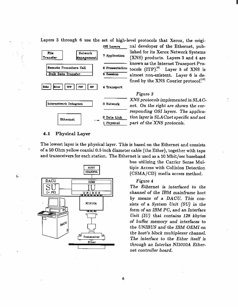
Layers 3 through 6 use the set of high-level protocols that Xerox, the origi- OS1 Layers
I,s.,I El 7 Application
Remote Procedure Call 6 Presentation
Bulk Data Transfer I 6 Session
Internetwork Datagrarn 3 Network
4.1 Physical Layer
The lowest layer is the physical layer. This is based on the Ethernet and consists
nal developer of the Ethernet, pub- lished for its Xerox Network Systems (XNS) products. Layers 3 and 4 are known as the Internet Transport Pro- tocols (ITP)!” Layer 5 of XNS is almost non-existent. Layer 6 is de- fined by the XNS Courier protoco1!101
Figure 3 XNS protocols implemented in SLAC- net. On the right are shown the cor- responding OS1 layers. The applica- tion layer is SLACnet specific and not part of the-XNS protocols.
of a 50 Ohm yellow coaxial 0.5 inch diameter cable (the Ether), together with taps and transceivers for each station. The Ethernet is used as a 10 Mbit/set baseband
bus utilizing the Carrier Sense Mul- tiple Access with Collision Detection (CSMA/CD) media access method.
Figure 4 The Ethernet is interfaced to the channel of the IBM mainframe host by means of a DACU. This con- sists of a System Unit (SU) in the form of an IBM PC, and an Interface Unit (IU) that contains 128 kbytes of buffer memory and interfaces to the UNIBUS and the IBM OEMI on the host’s block multiplexer channel. The interface to the Ether itself is
Ether
I through an Interlan NIlOlOA Ether- net controller board.
6
4.2 Link Layer
On the DEC VAX/VMS systems., the link layer consists of a DEUNA Ethernet interface board plugged into the UNIBUS interface. A single DEUNA in each VAX supports both SLACnet and DECnet.
For VM/SP an Interlan NIlOlOA Ethernet communications controller”” board is plugged into the UNIBUS of an IBM Device Attachment Control Unit (DACU)!17’ The DACU provides the capability to connect non-IBM input/output devices to the block multiplexer channel of IBM 43xx and 308x processors. On the non IBM side the DACU presents a UNIBUS interface. We chose the DACU since, being programmable, it is flexible, the program development environment (IBM PC) was well understood at SLAC, its price was attractive, and also it reduced the number of vendors involved.
- --rc .
4.3 Network and Transport Layers
At the time we started there were two major well defined candidates for the net- work and transport layer protocols. These were the XNS ITP and the DARPA TCP/IP protocols!271 Both of these protocols cover the network and transport layers. We chose the XNS/ITP protocols since we felt they are easier to imple- ment, and capable of higher performance. This is partially due to: larger address space; their use of fixed header fields; fewer options to implement and test; and, the fact that network layer checksums are optional and so time can be saved by not calculating them. In addition the fact that we were already running the XNS/ITP protocols in our Bridge terminal servers, meant any tools and learning from one system would be useful for the other. We purchased the sources of Interlan’s ITP [“I implementation for Unix* written in C, and ported this to the IBM VM/SP system!”
4.3.1 Network Layer
This layer addresses, routes and delivers standard internet packets over the net- work and makes a best effort to deliver them. Each packet is treated as an independent entity with no relation to other packets traversing the system. The XNS layer 3 protocol is the Internetwork Datagram Protocol (IDP).
* UNIX is a trademark of AT&T.
7
4.3.2 Transport Layer
The transport layer provides a transparent universal data transfer mechanism to the higher layers. The transport layer is expected to: check the integrity of the data delivered by the lower layers; and to optimize the use of available communication resources, while meeting the performance requirements of the higher layers. There are 5 XNS protocols defined at this layer:
l
l
The Sequenced Packet Protocol (SPP) g uarantees end-to-end transfers of data messages. The lower layers may lose packets, duplicate them, or get them out of order. SPP fixes this up, provides flow control and fragmen- tation of messages into packets, and reassembly of messages from packets. It also provides the functionality of multiple simultaneous virtual circuits. The SLACnet file transfer services utilize SPP. The Bridge Ethernet ter- minal servers also use the SPP as a basis for their terminal services.
The Packet ExchangrProtocol (PEP) r . . .
is used to transmit a request in a packet and receive a response with reliability greater than that achieved by IDP, and less than achievable through SPP. Bridge Communications also use PEP for network server management (e.g. gathering and reporting session records, configuration setting and querying). We have used the PEP support to allow VM/SP users to interrogate and set the Bridge terminal server configurations.
The Echo Protocol is used to verify the existence and correct operation of a host and the path to it. All Echo Protocol packets received are returned to the source.
The Error Protocol provides a means for any agent to report that it has noticed an error (and as a result discarded the packet). The agent sends the Error packet to the source socket of the packet that provoked the error. The contents of the Error packet include an error number and parameter, followed by the first portion of the offending packet.
The Routing Interchange Protocol (RIP) is the means by which the routing tables in each router are dynamically maintained. We have not made use of this protocol.
4.4 Session Layer
.I
The session layer binds together two cooperating user processes into a temporary relationship. Since the lower layers were based on the XNS ITP protocols, it was natural that we chose the XNS Listener paradigm to implement this layer. It listens at a well-known socket for a service request. Upon receiving a request, it sets up a connection between the initiator (in our case the file transfer master) and the server (in our case the file transfer slave), and then stands aside, returning to listen for more service requests.
4.5 Presentation Layer
The presentation layer services are concerned with data transformation, data formatting, and data syntax. The presentation layer is implemented using the XNS Courier [lo1 data encoding standard, and uses the XNS Courier Remote Procedure Call Protocol and Bulk Data Transfer Protocol.
4.5.1 Courier Remote Procedure Call Protocol
The remote procedure call protocol defines a single request-reply or transaction discipline for higher level applications. The active end issues call procedures which contain “arguments” (data items or input specific to the requirements of the called procedure) necessary to get the work done. The remote procedure is executed in the passive end and the result returned to the active end. If some- thing goes wrong, the procedure is aborted and an error statement returned.
The ASCII/EBCDIC and byte swapping data conversions are handled by spec- ifying Courier data types such as Integer (16 bits signed), Cardinal (16 bits unsigned), Long Integer (32 bits signed), String, Unspecified, Boolean, together with Arrays and Sequences of the above data types. The data items are con- verted to and from the network standards of the ASCII character set and IBM byte ordering.
4.5.2 Bulk Data-Transfer Protocol
Movement of large quantities of data would be inefficient to do via arguments to a remote procedure call. Therefore XNS provides a special adaptation of Courier called the Bulk Data Transfer Protocol. Bulk data is an arbitrarily long sequence of 8-bit bytes. The protocol specifies how the sender and receiver make contact, how the bulk data is demarcated, and how the transfer can be aborted by either party.
9
I
4.6 Application Layer
.
The application layer is the highest layer of the OS1 architecture. In our case the major application is the program that provides the file transfer services.
At the time we were implementing SLACnet, Xerox had not announced their filing protocol, nor were they willing to make a pre-announcement copy available to us. Thus we had to choose some other protocol. We looked at the DARPA FTP and TFTP file transfer protocols, and at the U.K. Blue Book protoco1!2a’ We chose to implement a stripped-down version of the Blue Book protocol!” It appeared to provide a more complete negotiation mechanism, and also specif- ically allows for the protocol to be extended in a way that provides backward compatibility.
p
The protocol dialogue takes place between a master (an active initiating process) and a slave (a passive respogding process). It is divided into 3 phases: .an initial- ization phase during which the 2 ends negotiate about the identity, properties and formatting details; the data transfer phase; and the termination phase.
During the negotiation phase, the slave is sent information as to what type of file is to be transferred, and whether the master node is an ASCII host and how its bytes and words are arranged. The slave then decides whether trans- lation between ASCII and EBCDIC, and/or byte or word swapping is required. If translation is required and the slave is an EBCDIC node then it will perform the translation in the bulk data phase, otherwise it will request the master to perform the translation. If byte/word swapping is required, then if the slave has DEC type byte/word ordering, it will perform the translation in the bulk data phase.
The sender of a file performs the required carriage control, tab expansion, record padding, and wrapping functions during the bulk data phase.
Either end may abort the file transfer by sending a bulk data abort message to the other end.
The termination phase is relatively simple. The master sends a STOP to the slave. The stop command contains the master’s final status information. The slave responds with a STOPACK reply, which also contains the completion sta- tus of the transfer from its point of view. If either end detected errors, then these (more than one error may be detected) are converted to appropriate er- ror messages at that end. Then the error messages, final status and statistics information are sent to the other end.
10

4.7 User Interface
From discussions with our users, we decided that users on a given machine prefer that all services ofi the machine’have a similar interface. This applies even if it means the user is presented with a different interface when using a corresponding service on another machine. Thus the user interface (the TRANSFER command) on the VAX end models a VMS COPY command: TRANSFER input-file-spec/options output-file-spec/options
whereas on VM/SP it looks a bit, like the SENDFILE command: EXPORT localfilespec TO remote-filespec AT node (options IMPORT localfilespec FROM remotefilespec AT node (options
In both cases the filespec of the remote file is expressed in the syntax of its native file system, and not parsed by the local end.
The file transfer service prcurides%he user with options to specify: 1
1. Character data, including conversion between EBCDIC and ASCII, and optional tab expansion.
2. Printer formatting support, optional conversion of embedded form feeds, line feeds, carriage returns to ANSI column 1 carriage control characters.
3. Binary data, VM/SP to VMS and vice-versa, and master to slave and vice- versa, including the byte and word swapping required between VAXes and IBM mainframes. No bit-level conversions such as floating point conversion are currently provided.
4. Changing record formats, e.g. fixed format to variable format, record trun- cation, wrapping, and padding. VMS null (zero length) records are con- verted to VM/SP records with a single pad character.
5. File copying attributes such as appending, replacing, creating.
6. The level of user notification, and who should be notified and where, when the file transfer is completed.
Table 1 is excerpted from the VM/SP HELP file and gives some idea of how the options are specified.
11

Table 1. User Options Available for the VM/SP SLACNET command
VM EXPORT/IMPORT Options
Options (defaults are underlined):
AUThorization “auth-str”
BRIef ] FULL ] DEBUG /* Terminal output */
NOCC 1 CC /* Carriage Control */
CHAracter ] BINary [4]wordsize] /* EBCDIC to ASCII,
or binary wordsize (needed for byte swapping)*/
CREate ] APPend [ONLY] ] REPlace [ONLY]
DEFaults [ QUEry] /* Used to change defaults */
INRecfm Variable]Fixed@gmerited ”
/* Segmented support allows a user to take records written with*/
/* a binary unformatted FORTRAN WRITE on one system, */
/* transfer them to another system, and read them */
‘/* with a binary unformatted FORTRAN READ.*/
NOTify Llvmid [VIA Msg]Rdr]Smsg] ] NONOTify
/* Can notify others when transfer done*/
OUTRecfm VariablelFixedlSegmented
PADcharacter c]xx] “c” /* Pad char for fixed len recs*/
RECLength i ] reel
TABstops DECprint]“cl c2 . . . cn”
-TRUncate ] NOTRUncate /* Over long lines are truncated?*/
WAR ] NOWAIt /* Transfer asynchronous of terminal?*/
WRAP ] NOWRAp /* Over long lines are wrapped?*/
4.7.1 VMS Examples
1. Same node VMS to VMS transfer with reformatting (assume input file is composed of variable length records): TRANSFER INFILE.DAT OUTFILE.DAT/FIXED/LRECL=80
2. Transfer from a VM/SP node: TRANSFER SLACVM#[JOE.l9l]T.FORTRAN DBAO:[JOHNIT.FOR TRANSFER YLACVM#[J~E IgilT FORTRAN" DBAO: [JOHN]T.FOR
12
. I
3 .
4 .7 .2
1 .
2 .
N o te s :
(a ) T h e u s e r m u s t u s e “.” i n th e V M /S P fi l e s p e c o r e n c l o s e i t i n q u o ta ti o n m a rk s . .
(b ) T h e re m o te n o d e n a m e (i n th i s c a s e S L A C V M ) i s p re p e n d e d to th e re - m o te fi l e s p e c a n d s e p a ra te d fro m i t b y a n i n s ta l l a ti o n s e l e c ta b l e s p e c i a l c h a ra c te r (# i n th e a b o v e e x a m p l e ).
T ra n s fe r to a V M /S P n o d e w i th th e fi l e g o i n g i n to th e re a d e r s p o o l o f th e re m o te V M /S P u s e ri d : T R A N S F E R D B A O :[F O R D l G U ID E .T E X ;4 2 S L A C V M # [Z A P H O D .R D R ]G U ID E .T E X N o te : R D R i s th e d e fa u l t d e v i c e fo r V M a n d m a y b e o m i tte d .
V M /S P E x a m p l e s
T o tra n s fe r s i m p l e c .F a c te y fi l e s b e tw e e n V M /S P a n d V M S : E X P O R T P R O F E X E C T O [P A T .D A T A IL O G IN .C O M A T M A c ( A u T H I " P A T p w d " IM P O R T B O O K S C R IP T A F R O M S L D ::[M C M IL L A N ]B O O K .R N O A T M A C
T o u s e S L A C n e t to s e n d a c h a ra c te r fi l e to a d i s ta n t D E C n e t n o d e : E X P O R T F N F T T O ' S L D "J O E p a s s w o rd tv ::[J O E ]J U N K .J N K ' A T M A C
N o te : It m a y h e l p to c h a n g e th e te rm i n a l d e fa u l t l o g i c a l e s c a p e c h a ra c te r, b e fo re i s s u i n g th i s c o m m a n d .
5 . V M /S P Im p l e m e n ta ti o n
T h e V M /S P e n v i ro n m e n t p ro v i d e s m u l ti p l e v i rtu a l m a c h i n e s , e a c h o f w h i c h ru n s i ts o w n o p e ra ti n g s y s te m . In o u r c a s e a l l th e v i rtu a l m a c h i n e s i n v o l v e d ru n th e IB M V M /S P C o n v e rs a ti o n a l M o n i to r S y s te m (C M S ). O u r d e s i g n tri e s to m i n i - m i z e th e n u m b e r o f v i rtu a l m a c h i n e s u s e d i n o rd e r to re d u c e th e i n te r-m a c h i n e c o m m u n i c a ti o n a c ti v i ty . T h i s a l s o e n a b l e s u s to s p e c i a l l y tre a t th i s s m a l l n u m - b e r o f v i rtu a l m a c h i n e s , i f i t i s fo u n d n e c e s s a ry , i n o rd e r to i m p ro v e p e rfo rm a n c e (e .g . b y l o c k i n g p a g e s i n to m e m o ry to re d u c e p a g i n g a c ti v i ty , o r b y fa v o ri n g th e v i rtu a l m a c h i n e ).
In te r-m a c h i n e c o m m u n i c a ti o n s a re h a n d l e d b y th e IB M In te r-U s e r C o m m u n i c a - ti o n V e h i c l e (IU C V ) fo r V M /S P !‘“’
1 3
5.1 Network Communication Executive (NCX)
Since CMS does not readily support asynchronous processes, something is re- quired to handle the networking’needs for concurrent tasks. NCX was designed by Interlan[“’ specifically for handling fast, efficient multitasking of PROCESSes, and provides an interface between the operating system (CMS or VMS) and the Network code. A PROCESS is a non-preemptable execution stream. PRO- CESSes are priority scheduled, running until EXITing or blocked by an explicit call (SLEEP, VIGIL, REQUEST) f rom within the PROCESS itself. A PROCESS can create (FORK) new (independent) PROCESSes. Shared Resources such as the Ethernet are represented by SEMAPHORES and can be REQUESTed and RELEASEd, by other PROCESSes or by interrupt level routines. PROCESSes can inter-communicate (SEND/RECEIVE) via MAILBOXes. REQUESTS and RECEIVES can time out. PROCESSes can dynamically allocate and free mem- ory. - --rc ”
We transported a Unix version (in C) to VM/SP, and later rewrote it in about 1300 lines of assembler code.
5.2 Link Layer
The DACU interface code uses three of the four available UNIBUS-type DACU subchannels. We modified* the VM/SP DIAGNOSE 20t function to support the DACU. Reads and writes use two Channel Command Words (CCWs) each. In order to provide reasonable performance (see section 6.2.1) and minimize the host impact, the DACU interface attempts to use large 56 kbyte buffers to transmit across the channel interface to the DACU (see Appendix A).
* Fortunately, we had access to the source code. t A VM/SP function that supports synchronous execution of a channel program on a general
I/O device.
14
5.3 Network and Transport Layers
Some of the reasons why we did not go to the extreme case where each user’s : virtual machine includes all software needed to run client programs as well
as ITP, are given elsewhere!“’ A further reason for isolating ITP in a sin- .- gle virtual machine is that this can facilitate its later replacement by intel- ligent hardware!“’ connected to the DACU that provides the ITP services.
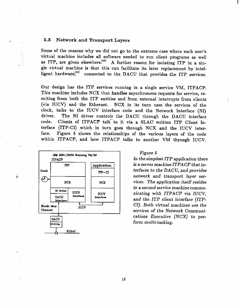
Our design has the ITP services running in a single service VM, ITPACP. This machine includes NCX that handles asynchronous requests for service, re- sulting from both the ITP entities and from external interrupts from clients (via IUCV) and the Ethernet. NCX in its turn uses the services of the clock, talks to the IUCV interface code and the Network Interface (NI) driver. The NI driver controls the DACU through the DACU interface code. Clients of ITPACP talk- to it via a SLAC written ITP Client In- terface (ITP-CI) which in turn goes through NCX and the IUCV inter- face. Figure 5 shows the relationships of the various layers of the code within ITPACP, and how ITPACP talks to another VM through IUCV.
IBM 3031/3033 BunnIng vM/SP ITPACP
ITP
I I Iucv
hbrlace , ,
I
1
1 Intafm.* 1 1
Block-MUX 1 t Iucv
channel t
DACU UllOloA
Figure 5 In the simplest ITP application there is a server machine ITPACP that in- terfaces to the DACU, and provides network and transport layer ser- vices. The application itself resides in a second service machine commu- nicating with ITPACP via IUCV, and the ITP client interface (ITP- Cl). Both virtual machines use the services of the Network Communi- cations Executive (NCX) to per- form multi-tasking.
A Ether Y
15
i 5.4 Session, Presentation and Application Layers
Initially the only client of ITP is the file transfer service. There are 2 sides to the file transfer service, the master (i’.e. the initiator or active side of the file transfer request), and the slave (i.e. the server or passive side of the request).
5.4.1 Master End
In conformance with the desire to minimize the number of virtual machines, the application and presentation layers are able to run in the same service VM as the session layer. However, this complicates the issue of adding other servers later since the servers are not isolated, and also the performance requirements of different servers may conflict (e.g. a file server does not need to be very interactive, whereas a message server or terminal server does). Other negative aspects to having all the FTP servers in a single service VM compared to being in separate service VMs am - c
1. The code has to be written more carefully since it is not single threaded;
2. The isolation between servers is reduced so there can be more unwanted interactions. One errant server can bring down the entire file server sys- tem. It can be harder to reproduce and pin-point problems due to the concurrency of processes.
Thus we usually run the master end of a file transfer in the user’s VM. This also has the advantage that the user can request that the file be written directly on one of his/her disks.
On VM/SP the file transfer can be executed in a WAIT or NOWAIT fashion. In the WAIT fashion the user’s VM executes the transfer synchronously and must wait until it is completed. When using the NOWAIT option the file transfer is executed on the user’s behalf by a service VM, FTPSERVE. Thus the user can initiate the request, and then get on with other work while the transfer is in progress. In either case the user interface of the master end parses the command, reports on errors, expands abbreviations, puts in system and user defaults, and creates a fully expanded request as a C structure.
1. If the WAIT option is requested, this C structure is simply passed to the file transfer program which executes in the user’s VM.
2. If the NOWAIT option is specified then the structure is passed as a spool file to FTPSERVE’s virtual reader. This awakens FTPSERVE which reads the file and passes it to the file transfer master program. The results of the file transfer may be passed back to the user VM via its reader, or an interactive message (MSG and/or SMSG). If the file was read to VM/SP then it is also transferred to the user VM via its reader.
16
i 5.4.2 Opening the Session
The master end of a file transfer request sends an SPP Open request to the well- : known listener socket at the remote node. The listener at the remote node (run-
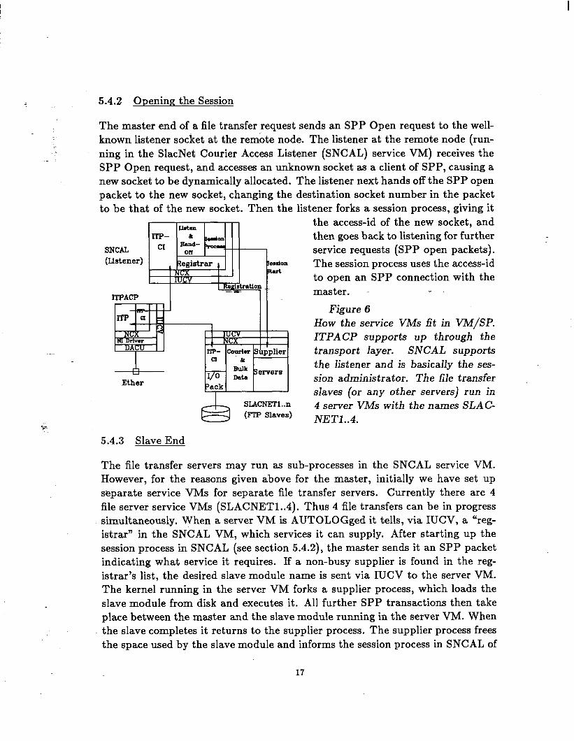
ning in the SlacNet Courier Access Listener (SNCAL) service VM) receives the .- SPP Open request, and accesses an unknown socket as a client of SPP, causing a new socket to be dynamically allocated. The listener next hands off the SPP open packet to the new socket, changing the destination socket number in the packet to be that of the new socket. Then the listener forks a session process, giving it
SNCAL (Listener)
ITPACP
the access-id of the new socket, and then goes back to listening for further service requests (SPP open packets). The session process uses the access-id to open an SPP connection with the master. i
Figure 6 How the service VMs fit in VM/SP. ITPACP supports up through the transport layer. SNCAL supports the listener and is basically the ses- sion administrator. The file transfer slaves (or any other servers) run in 4 server VMs with the names SLAC- NET1 ..4.
5.4.3 Slave End
The file transfer servers may run as sub-processes in the SNCAL service VM. However, for the reasons given above for the master, initially we have set up separate service VMs for separate file transfer servers. Currently there are 4 file server service VMs (SLACNET1..4). Thus 4 file transfers can be in progress simultaneously. When a server VM is AUTOLOGged it tells, via IUCV, a “reg- istrar” in the SNCAL VM, which services it can supply. After starting up the session process in SNCAL ( see section 5.4.2), the master sends it an SPP packet indicating what service it requires. If a non-busy supplier is found in the reg- istrar’s list, the desired slave module name is sent via IUCV to the server VM. The kernel running in the server VM forks a supplier process, which loads the slave module from disk and executes it. All further SPP transactions then take place between the master and the slave module running in the server VM. When the slave completes it returns to the supplier process. The supplier process frees the space used by the slave module and informs the session process in SNCAL of
17
its completion and exits. The session process in SNCAL then marks the server VM non-busy in the registrar’s list and also exits.
If no matching no-busy supplier can be found, then the SPP Open attempt will time out.
In order to reduce paging of code, the file transfer code has been written so the majority of the code is re-entrant and only a single shared copy of the re-entrant code will be required. So far we have not taken advantage of this.
5.5 Error Messages
On VMS we use the standard VMS message utilities!“] On VM/SP we model the VMS scheme. All error messages are assigned a 32-bit number, called the message code. The message code contains the facility (e.g. Ethernet interface, file transfer master, I/O interface) thatsenerates the message, the message number within the facility, and the severity of the error. The developerYof each facility is assigned a facility number, and produces a file with all the message codes and their related text. On VM/SP a utility processes these files to create a DisContiguous Shared Segment (allows multiple VMs to share common memory), that contains the information. When an error occurs, the message code is used to call a procedure that returns the complete error message text.
5.6 VM/SP Disk I/O Package (ioPack)
In order to allow the file transfer master and slave to be transportable, we defined a host-independent set of C callable routines to support disk I/O. These were implemented for VMS and VM/SP and present the same interface to the caller irrespective of the machine on which they are being called. However, the error codes returned are specific to the local system. The application code uses the error code together with the message system described in section 5.5, to obtain an error message.
The disk I/O package supports reading and writing to CMS minidisks, and writ- ing to a spool file (reader, printer, or punch). All the usual CMS file modes are supported including mode 4 for VBS records, which are used for FORTRAN un- formatted binary records. Punch files utilize the Cornell CARD DUMP format, which allows transmission of files of any record length.
18

5.7 LINK Passwords
VM/SP keeps count of the number of password violations made trying to LINK to a disk. If this exceeds about 10, then that VM is barred from making further LINK attempts during the logged on session. In order to prevent this happening to a file transfer server VM, the listener checks the password violation count of a server machine before asking it to perform the file transfer. Should the count be exceeded, a process is started to wait for the completion of all file transfers in that server machine. At that time, the server machine is FORCEd and AUTOLOGged by the listener if (a) the error condition still exists and (b) the server belongs to the family of SLACNET1..4 servers. Crude, but it works, requires no mods to the VM/SP Control Program (CP), and only the listener needs privileges.
5.8 VM Synchronization
Any of the service VMs (mAL,?ITPACP, SLACNET1..4, FTPSERVE) can be FORCEd and AUTOLOGged in case of problems. The VMs will automatically get back into step when one of them is AUTOLOGged. This enables us to take one of the VMs down, fix bugs, add enhancements etc., and then easily restore
. . it to service.
6. Performance
6.1 VMS
The DEUNA is rated at about 180 kbytes/sec when transmitting data onto the Ethernet.
In a VAX 11/780, reading and writing SPP messages takes about 16 msec cpu time in the ITPACP process and 2.5 msec cpu time in the user process. The maximum SPP message rate was around lO/sec.
For our type of data (binary unformatted FORTRAN data), the VAX 11/780 VMS disk read rate is around 250 kbytes/sec, and the write rate is about 130 kbytes/sec.
Bulk data transfer disk to disk with the producer and consumer on the same VAX 11/780, runs at 30 kbytes/sec for large binary files. Doing this, the peak utilization takes 6-8% of the cpu to support the producer, about 7-9% to support the consumer, and ITP takes 55% (n.b. since both producer and consumer are on the same VAX, this will drop by a factor of 2 when using 2 VAXes).
Transferring a file from a VAX 11/780 running VMS to VM takes about 55% of the VAX cpu cycles. On a VAX 8600 this drops to 20%.
19
i 6.2 VM
: 6.2.1 Link Layer.
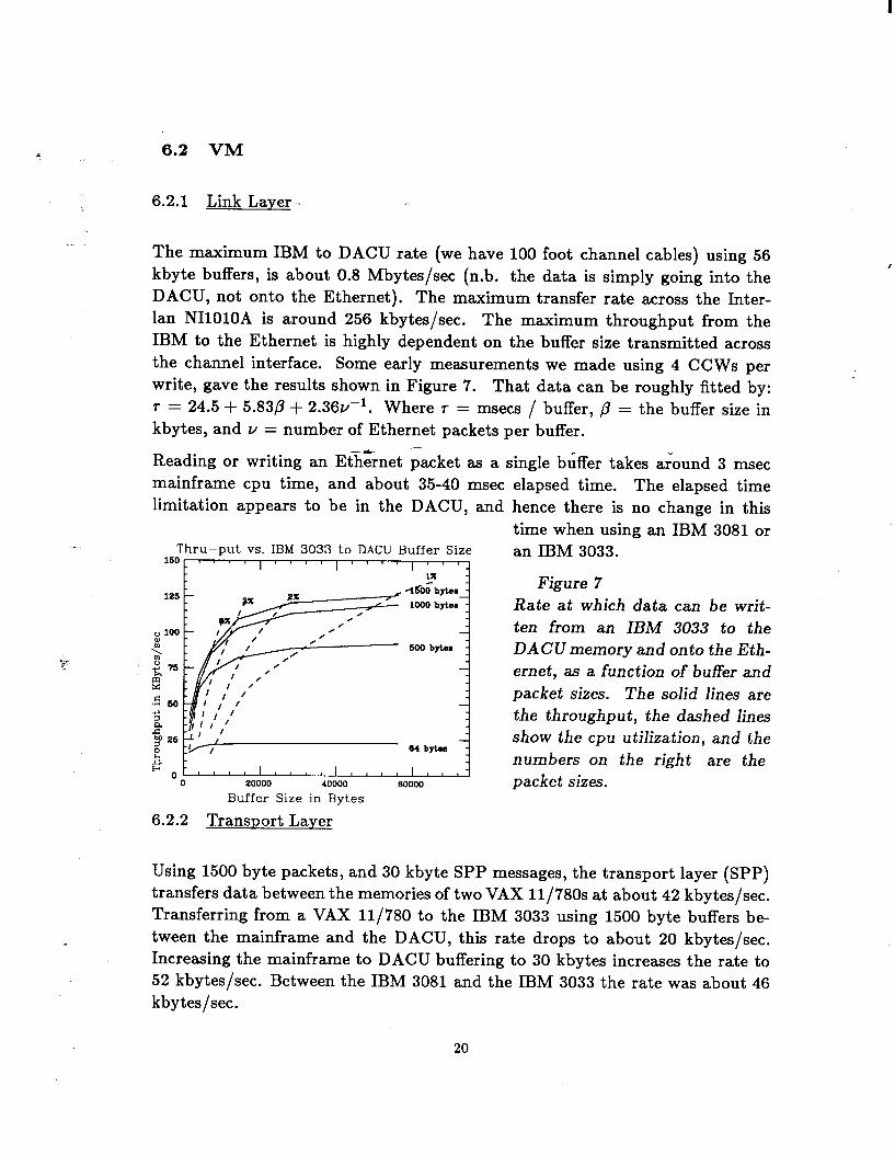
The maximum IBM to DACU rate (we have 100 foot channel cables) using 56 kbyte buffers, is about 0.8 Mbytes/set (n.b. the data is simply going into the DACU, not onto the Ethernet). The maximum transfer rate across the Inter- lan NIlOlOA is around 256 kbytes/sec. The maximum throughput from the IBM to the Ethernet is highly dependent on the buffer size transmitted across the channel interface. Some early measurements we made using 4 CCWs per write, gave the results shown in Figure 7. That data can be roughly fitted by: r = 24.5 + 5.83p + 2.36u- l. Where r = msecs / buffer, p = the buffer size in kbytes, and Y = number of Ethernet packets per buffer.
- Reading or writing an Et&&net packet as a single buffer takes around 3 msec mainframe cpu time, and about 35-40 msec limitation appears to be in the DACU, and
Thru-put vs. IBM 3033 to DACU Buffer Size 16Oc I I I I
I
1000 bytem
600 bytam
64 bytom
0 20000 40000 BOO00
Buffer Size in Bytes
elapsed time. The elapsed time hence there is no change in this time when using an IBM 3081 or an IBM 3033.
Figure 7 Rate at which data can be writ- ten from an IBM 3033 to the DACUmemory and onto the Eth- ernet, as a function of buffer and packet sizes. The solid lines are the throughput, the dashed lines show the cpu utilization, and the numbers on the right are the packet sizes.
6.2.2 Transport Layer
Using 1500 byte packets, and 30 kbyte SPP messages, the transport layer (SPP) transfers data between the memories of two VAX 11/78Os at about 42 kbytes/sec. Transferring from a VAX 11/780 to the IBM 3033 using 1500 byte buffers be- tween the mainframe and the DACU, this rate drops to about 20 kbytes/sec. Increasing the mainframe to DACU buffering to 30 kbytes increases the rate to 52 kbytes/sec. Between the IBM 3081 and the IBM 3033 the rate was about 46 kbytes/sec.
20
6.2.3 File Transfer Layer
: The following measurements are made with 1500 byte Ethernet packets, 31000 byte bulk data buffers, and no X& checksum* calculations. All the timings are wall clock times. The VM/SP end is an IBM 3033. Multiple packets are collected in the DACU and transferred via a single large buffer to the 3033.
Time for VAX to start FTP slave process image: 4,500ms Time to read a single packet buffer 24ms Time to read a IO-packet buffer 43ms (Time/packet after 1st packet in buffer) 2ms
(1) (2)
(3)
Notes:
. .
1. At the remote end the Courier remote procedure call listener starts a file transfer service process by performing a remote login with the appropriate access string for the specified user account. The time to perform this remote login depends on how heavily the VAX is loaded, etc. The average we observed is around 5 sets, and 80% of the remote logins are performed in under 20 sets. This is on a reasonably loaded VAX 11/780. Thus if small files are transferred, a major fraction of the time goes into the remote login if this has to be done for each file transfer.
2. This time is basically the latency of the DACU, i.e. the time it takes to
F~ respond to the mainframe. A faster PC in the DACU might help.
3. This indicates the importance of performing buffering between the host and the DACU. Note that the instantaneous transfer rate is around 750 kbytes/sec.
k2.3.1 File Transfer Rates (Disk to Disk) The following timings were made during the daytime. They are made between separate computers. The timings typically varied by about 10% from measurement to measurement. Using DCSSs to share data across VMs, rather than copying the data, had a negligible effect on performance. The window size (see note 2 below) if not specified is 3. The VMS end is a VAX 11/780 unless specified. The VM end is an IBM 3033. The file is a 3 Mbyte binary filet of variable records of average length 1500 bytes, maximum
* Turning on the checksum calculations does not alter the VM/SP to VM/SP transfer rates, but does increase the cpu utilization of ITPACP by about 30%.
t This file happened to be a convenient 3 Mbyte file that was sitting around, and is truly typical of the stuff we have to shovel around. Using a file of 80 byte records, typically reduced the performance by 25%.
21
p
length 21 kbytes and minimum length 44 bytes. The packet size is 1500 bytes. Going from 1500 byte packets to 500 byte packets reduced the performance at the transport layer by 30%. ,
VMS to VMS: 30 kbytes/s VMS to VM (no DACU buffering (buffer = 1 pkt)) 18 kbytes/s VMS to VM (with buffering, window size 10) 31 kbytes/s (1) VMS to VM (with buffering, window size 20) 36 kbytes/s (2) VMS to VM (with buffering, window size 25) 40 kbytes/s (2) VMS(8600) to VM (with buffering, window size 20150 kbytes/s (3) VMS(8600) to VM (with buffering, window size 25)55 kbytes/s (3) VM to VM no buffered write, buffered read 30 kbytes/s VM to VM buffered read and write 40 kbytes/s (4)
Notes: - -6 1. Shows the importance of DACU-to-mainframe buffering.
2. Showstheimportance ofusinglarge acknowledgewindows (i.e. the number of packets that can be outstanding at the receiver before it must acknowl- edge the receipt of at least one of them). Small windows mean that the DACU must constantly interrupt the mainframe to report the receipt of an acknowledgement.
3. Shows that the DACU is not the only limit; a faster VAX helps too.
4. The aggregate transfer rate when running two transfers simultaneously, i.e. IBM 3033 to IBM 3081, and IBM 3081 to IBM 3033, was also about 40 kbytes/sec (20 kbytes/sec in each direction).
6.2.3.2 CPU Impact on IBM 3033: Channel Busy (no DACU Buffering)
-Channel Busy (with buffering) IBM 3033 CPU Utilization worst case
50% 10% 12% (1)
Notes:
1. 65% of this 12% was in ITPACP.
22
I
7. Code
7.1 Source Code
On both the VAXes and the IBM mainframes the bulk of the code is in C, with the remainder being in assembler, and in the case of the IBM mainframes, REXX. The DACU code was written in Pascal, since this language is supported by the DACU support programs.
On VMS the Interlan code was written for the Whitesmith C compiler. We modified it to run under the DEC VAX C compiler!231
On VM/SP at first we used the Canaan modified Bell C compiler in production. Recently we changed over to the Waterloo C compiler!3o1 It creates 30% less object code, and runs 30% faster. Also it is supported by the SLAC computer services people whereas the Canaan compiler is not. Since the Waterloo compiler is relatively new, we did enco’uf;ter some bugs, which Waterloo have been responsive in fixing. There were also some naming conflicts with our code and the Waterloo run-time library, and different interpretations on a couple of subtle boundary conditions in the string handling routines, arrays of structures, and imbedding comments in literal strings. .Unfortunately the Waterloo compiler uses an unusual procedure calling convention, so we also had to modify the receiving sequence in the NCX and the disk I/O package.
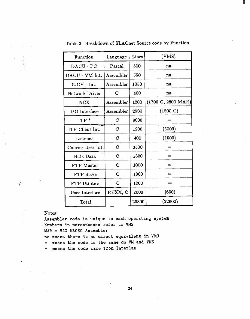
The total number of lines of code is around 33,000. Tables 2 and 3 below show how this is broken up, by function and language.
23
I
Notes:
Table 2. Breakdown of SLACnet Source code by Function
=
Bulk Data C 1500 =
FTP Master C 1000 =
FTP Slave C 1000 =
FTP Utilities C 1000 =
User Interface REXX, C 2600 (600)
I Total 26800 (22600)
Assembler code is unique to each operating system Numbers in parentheses refer to VMS MAR = VAX MACRO Assembler na means there is no direct equivalent in VMS = means the code is the same on VM and VMS * means the code came from Interlan
24
:
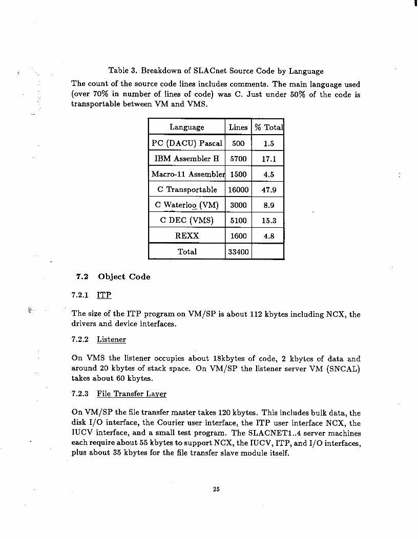
Table 3. Breakdown of SLACnet Source Code by Language
The count of the source code lines includes comments. The main language used (over 70% in number of lines of code) was C. Just under 50% of the code is transportable between VM and VMS.
.- I I I Language 1 Lines
I C Transportable --116ooo
C Waterloo (VM) 3000
I Total 133400
% Tota
1.5
17.1
4.5
47.9
8.9
15.3
4.8
7.2 Object Code
7.2.1 ITP
Ft- The size of the ITP program on VM/SP is about 112 kbytes including NCX, the drivers and device interfaces.
7.2.2 Listener
On VMS the listener occupies about 18kbytes of code, 2 kbytes of data and around 20 kbytes of stack space. On VM/SP the listener server VM (SNCAL) takes about 60 kbytes.
7.2.3 File Transfer Layer
On VM/SP the file transfer master takes 120 kbytes. This includes bulk data, the disk I/O interface, the Courier user interface, the ITP user interface NCX, the IUCV interface, and a small test program. The SLACNET1..4 server machines each require about 55 kbytes to support NCX, the IUCV, ITP, and I/O interfaces, plus about 35 kbytes for the file transfer slave module itself.
25
8. Statistics Gathering and Accounting
8.1 Accounting
Both the master and slave ends of the VM/SP file transfer service gather the fol- lowing data: requesting userid; source filespec; target filespec; transfer direction; FTP return code; master and slave version numbers; number of bytes transferred; number of records transferred. This information is concatenated into one line of fixed length, and the VM/SP special message feature SMSG is used to send it to a service VM, which logs it onto a disk file. The disk file is archived to tape when it reaches a certain threshold. The file is accessible publicly and can be viewed using the VM/SP editor. The data is analyzed on a monthly basis using locally written SAS’311 procedures.
8.2 Network Management -
8.2.1 Real Time Monitoring
. . Real time monitoring of the network traffic is performed by means of NET- MON, a VM/SP version of NETMGR, an Interlan program”’ for their Ethernet products. NETMON is a menu-driven, screen-oriented program for 327x type terminals that allows inspection of local and remote network statistics and con- figuration information. Four displays are available: 1) general ITP statistics; 2) ITP network statistics; 3) ITP socket statistics; and 4) connection statistics.
.
8.2.2 Probing the Network
To enable VM/SP users or operators to check whether the network is running, the QSNET exec checks the components.
. 1. It ensures that FTPSERVE, ITPACP, SNCAL and SLACNET1..4 are logged on, that the DACU is correctly attached, ITPACP can talk to it, ITPACP on SLACVM is responding correctly, and can probe the ITP layer at each remote SLACnet node.
2. It can also:
(a) Try some trivial file transfers to check the working of the FTP software.
(b) Show which DECnet nodes are connected to a specified SLACnet node.
(c) Show the SLACnet network table.
(d) Show various online ITP and network counters.
26

9. Discussion
9.1 Choices
In the early days we had to make many choices concerning which standards to follow, hardware to use, and language to develop code in. Some observations concerning our decisions follow:
DACU: The DACU hardware has been extremely reliable, with no failures be- ing observed in any of our 3 DACUs. Twice in the last 2 years a DACU has needed manual intervention to reboot it after a short (less than 10 second) power fluctuation locked up the PC. The performance, however, leaves something to be desired. A large fraction of the development effort was consumed in improving the DACU to mainframe performance. We also ran into a serious problem with UNIBUS transfers (e.g. re$ing &he Control Status Register (CSR)) being cor- rupted by Direct Memory Address (DMA) transfers from the NIlblOA. IBM is looking at the problem, but for the moment we have had to turn on the IDP checksumming in order to insure the integrity of our data.
. .
=.
Protocols: Though we still feel that the XNS protocols are optimal for a local area Ethernet, the lack of high-level applications to talk to is a serious limitation to its development as a standard. Some of the blame for this must be attributed to the delays in making the applications layer protocols public.
Language: C has turned out to be very adequate for the development. The conversions in mid-stream from Whitesmith C to DEC VAX C and Bell C/370 to Waterloo C, probably cost us about 1 man-month.
9.2 Differences between the VMS and VM Environments
Since we were implementing protocols to run under both these systems, we be- came acutely aware of the following major differences:
1. The lack of multi-tasking support inside CMS required the development of NCX. Many long, almost religious, discussions were held concerning how many service VMs should be used, ranging from every VMS process running as a separate service VM on VM/SP, to the whole of SLACnet running in a single service VM.
2. EBCDIC versus ASCII character sets, and the different byte/word ordering.
3. File system differences, particularly: file name lengths; use of delimiters (periods versus space); the maximum permissible logical record lengths; and treatment of zero length records, carriage control and tabs.
27
I
4. VMS allows a single account to be logged onto by several users simultane- ously, whereas on VM/SP an account may only be logged onto by a single user at a time. In addition on VMS the logon password and disk file pass-
.- words are one and the same, whereas on VM/SP different passwords may .- be used. Because of these two differences the VMS and VM/SP listeners
differ. On VMS the listener performs a remote logon of the account asso- ciated with the disk file to be transferred, thus providing the appropriate disk access environment. On VM/SP no remote logon is performed; the password is simply passed to the disk I/O package when the disk is to be LINKed.
5. The lack of an integrated program development environment on VM/SP contrasts sadly with that in VMS, with its language sensitive editor, its standard procedure calling convention, its standard set of system procedure calls for all languages, full-screen symbolic debugger for all languages, code management system,Ftc. Admittedly REXX is -markedly superior to the DEC VAX DCL language; however, less than 5% of our code was in REXX.
6. The lack of an IBM supported system level symbolic debugger required the development of such a tool to provide instruction and interrupt tracing, in- cluding symbol name support, tracebacks, and the ability for a programmer to log on and initiate, resume or terminate debugging or program analysis at any time.
VM/SP has provided a very robust base on which to develop SLACnet. In 2 years of development done on a production VM/SP mainframe, negligible system test time has been required. CP has only crashed twice due to our exposing system code errors. Once this was due to an IBM fix to a bug in using IUCV send with a 1 way message with parameter data. The other was in the area of interfacing to the DACU, when we were trying to perform I/O and field attentions on the same subchannel. Both problems were quickly by-passed.
9.3 Performance
The limits to the file transfer performance appear to be in the transport layer and below. We have looked at off-loading the transport layer functions out of the mainframe. Such hardware is becoming available, for example from Micom- Interlan~lal that handles ITP on a board that plugs into a UNIBUS. However, it is designed for a host that can directly access the board’s memory. It is not clear whether it could effectively be used to obtain higher performance with a DACU with its limited number of subchannels and memory space, and the way it isolates the UNIBUS device from the mainframe.
28
10. Acknowledgements
The authors acknowledge Roy Miller for developing the symbolic debugger, pro- .- viding guidance in using it, and providing consultation on some of the system
._ aspects of VM/SP. We are also very grateful for many long and instructive discus- sions on VM/SP/CP/CMS with Bill Weeks and Ted Johnston. We thank Gary Bower for his contributions early on in the design of the file transfer service. Joe Wells provided much useful background to the philosophy of VM/SP, and specific information on PC file transfer to and from VM/SP. John Halperin also provided useful guidance during the early stages. John Brown labored hard to inject reality into our lofty goals. Steve Willis and Bill Siefert, both of Interlan, provided much useful help on using the Interlan ITP and NCX packages. Finally, debts are due to Marvin Weinstein for explaining how to format this document in TeX and how to imbed the graphics, and to Billie Bennett for Figures 1 and 2. -rC
A. Appendix: Details on the Use of the DACU
We are running release 4.0 of the DACU code from, using three of the four available UNIBUS-type DACU subchannels.
.
A.1 Subchannel 4, Control
Control transactions between ITPACP (the service VM supporting the network and transport layers) and the DACU Pascal program such as: buffered read/write setup (buffer size, timeout parameters); executing dataless control commands to the NIlOlOA; writing broadcast addresses to the NIlOlOA; reading the NIlOlOA statistics buffer.
A.2 Subchannel 5, Buffered Write
Packets are buffered into a 56 kbyte write buffer. Within the buffer, packets are preceded by control words indicating the next packet’s length or end of buffer. When the mainframe has a buffer ready to be written, it makes a single DI- AGNOSE 20 call to send two CCWs. One of these acknowledges the attention from the DACU that was presented when the DACU completed the previous write. The second CCW does the actual data transfer to the DACU buffer. The DACU receives an interrupt at the end of the channel program, and automat- ically presents channel end to the mainframe. As soon as the DACU program
29
sees the interrupt it sends a device end to the mainframe, thus completing* the DIAGNOSE 20.
.- The DACU program gives the NIlOlOA the start address and length of the first packet stored in the buffer, starts a transfer to the Ethernet, and watches the NIlOlOA Control Status Register until the transfer is complete. This sequence is repeated until all packets have been transferred from the DACU buffer, where- upon the DACU program sends an attention to the mainframe to say it is ready to accept a further write from the mainframe.
After each write of a packet to the Ethernet, the DACU program checks the NIlOlOA to see if a read has completed. If so, a new read is started.
A.3 Subchannel 6, Buffered Read
Packets are buffered into-a-64 kbyte read buffer. When the mainframe DACU _ support program starts, it passes the DACU two timeout counters. One gives the maximum time to wait between packets before transferring the buffer to the mainframe. We use 20 msec for this timer. The second gives the maximum time, measured from reading the first packet into the buffer, after which the buffer will be transferred to the mainframe. We use 0.5 set for this timer. The DACU program presents the NIlOlOA with the buffer transfer address for the next Ethernet packet read, this also tells the NIlOlOA to transfer a packet (when it has one) to the DACU memory via a DMA transfer. The DACU program then checks the NIlOlOA CSR at frequent intervals to see if a packet has been read into the DACU memory from the NIlOlOA. When a packet is read, the DACU program checks whether the timeouts have been exceeded, or the buffer is full. If so, it sets the DACU channel registers that tells the mainframe where to read the data from, and sends an attention to the host. If there is free space in the buffer, then the DACU program presents the NIlOlOA with the next buffer transfer address.
The mainframe receives the attention from the DACU to say that there is a buffer to read. The mainframe makes a single call to DIAGNOSE 20 to send two CCWs, one to acknowledge the attention, the second to read the DACU buffer. When the read completes, the DACU is interrupted, and can then reuse the buffer. The NIlOlOA itself can accept up to nine 1500 byte packets (about 30msec for back-to-back packets), before it needs to be read.
* The elapsed time from calling the DIAGNOSE 20, executing the channel program, and the mainframe seeing the device end and returning from DIAGNOSE 20, is about 12 msec plus 1.9 msec for each 1500 bytes transferred.
30
B. Appendix: Client Interfaces
B.l Network Layer
The network layer is supported by the following C language callable procedures: echacc - Get access as a client of the Echo Protocol echreq - Transmit an Echo packet
idpacc - Get access as a client of IDP idpxmt - Transmit an IDP packet idptrcv - Receive an IDP packet and truncate the remainder idphrcv - Receive an IDP packet and hold the remainder
B.2 Transport Layer _ -6 r
The following C language callable procedures provide the program interface to SPP:
. .
R.
sppacc - Access the transport layer as a client of SPP sPPxmt - Send an SPP packet over an SPP connection spptrcv - Receive an SPP packet and truncate the remainder spphrcv - Receive an SPP packet and keep the remainder sppforce - Hand off a packet to a local SPP socket sppclose - Close an SPP connection
The following PEP procedures provide an interface to PEP: PePareQ - Access as a PEP requester pepxreq - Transmit a PEP request and wait for response PePtreq - Receive a PEP response and truncate the remainder pephreq - Receive a PEP response and hold the remainder ‘pepares - Access as a PEP responder pepxre s - Transmit a PEP response peptres - Receive a PEP request and truncate the remainder pephre s - Receive a PEP request and hold the remainder
In addition the following general ITP procedures are used by all transport layer protocol clients:
deaccess - Terminate an ITP access itpini - Initialize the ITP user interface itpclose - Close the ITP user interface
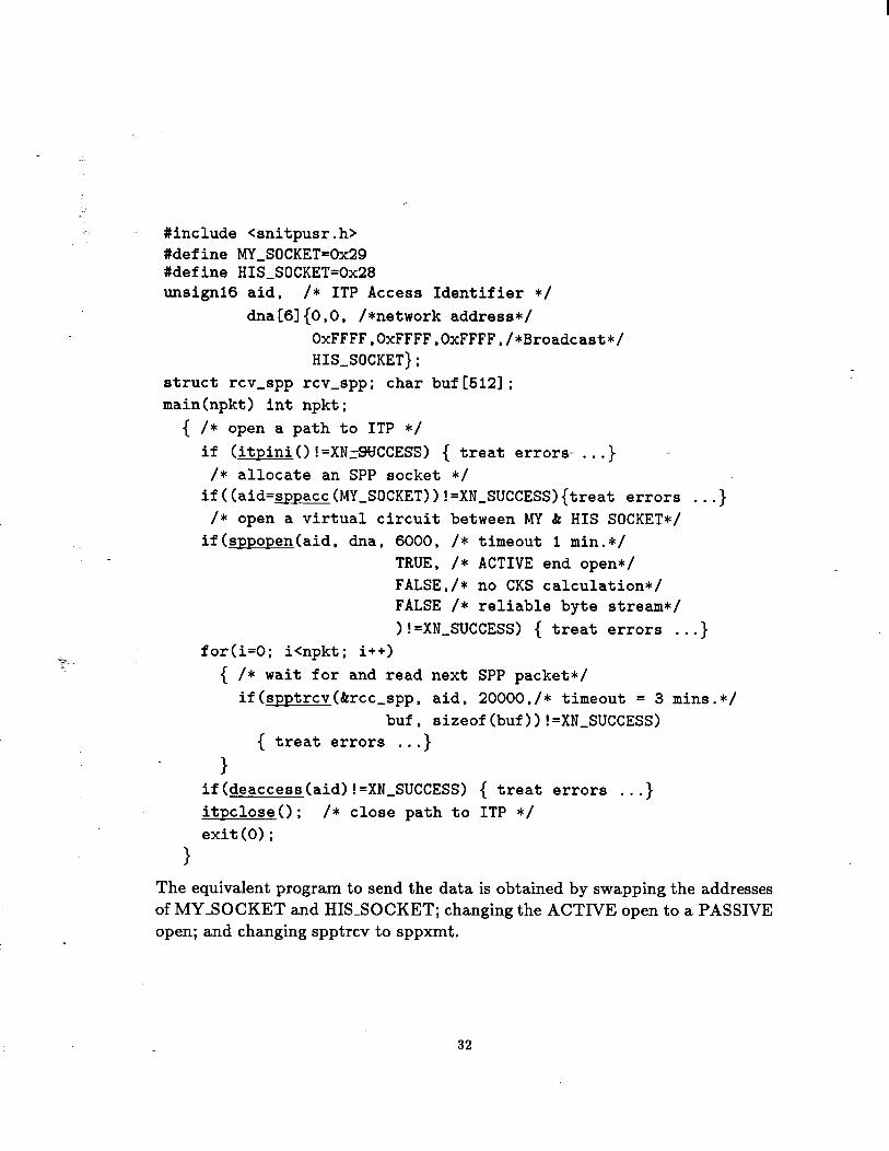
An example of a simple C program to receive data from another node, using the facilities of ITP, is shown below. The SLACnet ITP procedures are underlined.
31
#include <snitpusr.h> #define MY_SOCKET=Ox29 #define HIS_SOCKET=Ox28 unsignl6 aid, /* ITP Access Identifier */
dna[6]{0,0, /*network address*/ OxFFFF.OxFFFF.OxFFFF./*Broadcast*/ HIS-SOCKET};
struct rev-spp rev-spp; char buf[512]; main(npkt) int npkt;
{ /* open a path to ITP */ if (itpinio !=XN:SUCCESS) { treat errors- . ..} 1
/* allocate an SPP socket */ if((aid=sppacc(MY-SOCKET))!=XN_SUCCESS){treat errors . ..}
/* open a virtual circuit between MY & HIS SOCKET*/ if(sppopen(aid. dna, 6000. /* timeout 1 min.*/
TRUE, /* ACTIVE end open*/ FALSE,/* no CKS calculation*/ FALSE /* reliable byte stream*/ )!=XN,SUCCESS) { treat errors . ..}
for(i=O; icnpkt; i++) { /* wait for and read next SPP packet*/
if(spptrcv(&rcc-spp, aid, 20000,/* timeout = 3 mins.*/ buf, sizeof(buf)) !=XN-SUCCESS)
{ treat errors . . 4 1
if(deaccess(aid)!=XN_SUCCESS) { treat errors . ..} itpclose(); /* close path to ITP */ exit(O);
1
The equivalent program to send the data is obtained by swappingthe addresses of MY-SOCKET and HIS-SOCKET; changing the ACTIVE open to a PASSIVE open; and changing spptrcv to sppxmt.
32
B.3 Courier Remote Procedure Call
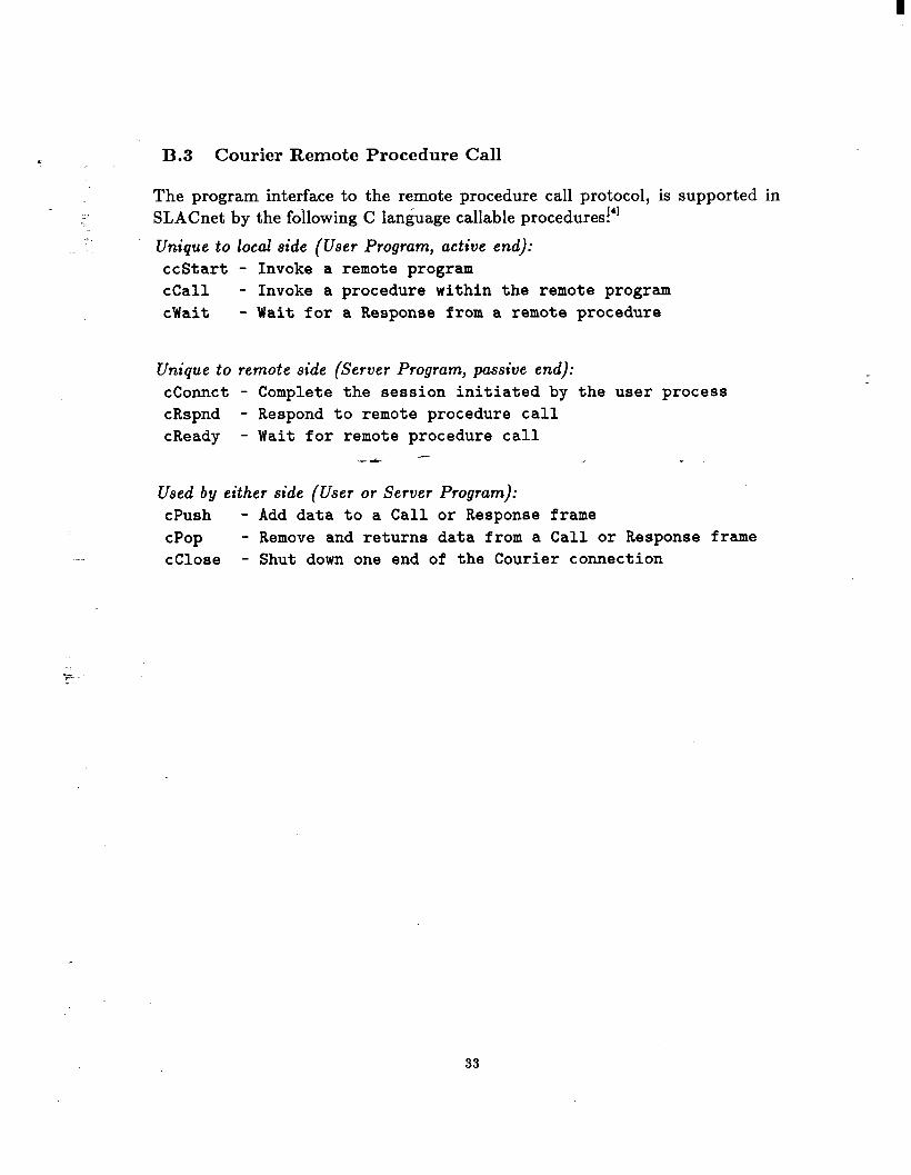
The program interface to the remote procedure call protocol, is supported in SLACnet by the following C language callable procedures!']
Unique to local side (User Program, active end): ccStart - Invoke a remote program cCal1 - Invoke a procedure within the remote program cWait - Wait for a Response from a remote procedure
Unique to remote side (Server Program, passive end): cConnct - Complete the session initiated by the user process cRspnd - Respond to remote procedure call cReady - Wait for remote procedure call
- -rC s
Used by either side (User or Server Program): cPush - Add data to a Call or Response frame cPop - Remove and returns data from a Call or Response frame cClose - Shut down one end of the Courier connection
33
.-
_.
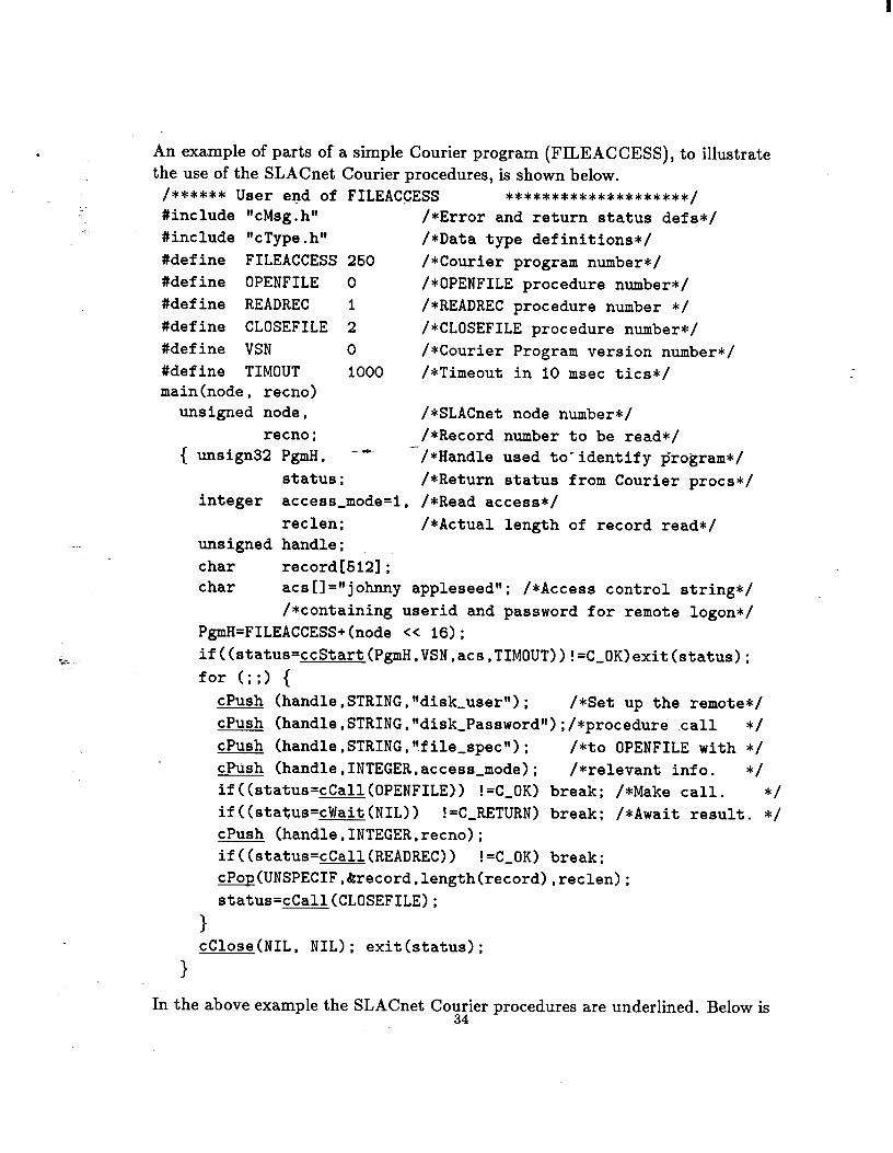
An example of parts of a simple Courier program (FILEACCESS), to illustrate the use of the SLACnet Courier procedures, is shown below.
/****** User end of FILEACCESS ***************SC****/ #include "cMsg.hw /*Error and return status defs*/ #include I1 T c ype.h" /*Data type definitions*/ #define FILEACCESS 260 /*Courier program number*/ #define OPENFILE 0 /*OPENFILE procedure number*/ #define READREC 1 /*READREC procedure number */ #define CLOSEFILE 2 /*CLOSEFILE procedure number*/ #define VSN 0 /*Courier Program version number*/ #define TIMOUT 1000 /*Timeout in 10 msec tics*/ main(node. recno)
unsigned node, /*SLACnet node number*/ recno; /*Record number to be read*/
{ unsign32 PgmH, -- -/*Handle used to-identify program*/ status; /*Return status from Courier procs*/
integer access-mode=i, /*Read access*/ reclen; /*Actual length of record read*/
unsigned handle; char record[512]; char acs [I ="johnny appleseed"; /*Access control string*/
/*containing userid and password for remote logon*/ PgmH=FILEACCESS+(node CC 16); if((status=ccStart(PgmH,VSN,acs.TIMOUT))!=C-OK)exit(status); for (;;I {
(handle,STRING,t'disk,usertt); cPush /*Set up the remote*/ */ cPush (handle,STRING,wdisk,Passwordw);/*procedure call
cPush (handle,STRING.wfile_spec"); /*to OPENFILE with */ cPush (handle,INTEGER,access_mode); /*relevant info. */ if((status=cCall(OPENFILE)) !=C-OK) break; /*Make call. */ if((status=cWait(NIL)) !=C-RETURN) break: /*Await result. */ cPush (handle,INTEGER,recno); if((status=cCall(READREC)) !=C-OK) break; cPop(UNSPECIF,&record,length(record),reclen); status=cCall(CLOSEFILE);
1 cClose(NIL, NIL); exit(status);
In the above example the SLACnet Co;:ier procedures are underlined. Below is
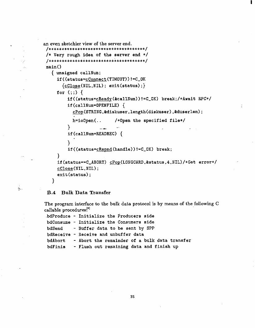
an even sketchier view of the server end. /*************************************/ /* Very rough idea of the server end */ /*************i************************/ main0
{ unsigned callNum; if((status=cConnect(TIMOUT)) !=C-OK
{cClose(NIL,NIL); exit(status);} for (;;I {
if((status=cReadp(&callNum))!=C_OK) break;/*Await RPC*/ if(callNum=OPENFILE) {
cPop(STRING,&diskuser,length(diskuser).&serlen):
h=ioOpen(.. /*Open the specified file*/
) - if(callNum=REAGREC) {
r
1 if((status=cRspnd(handle)) !=C,OK) break;
1 if(status==C-ABORT) cPop(LONGCARD,&status,4,NIL)/*Get error*/ cClose(NIL.NIL); exit(status);
1
B.4 Bulk Data Transfer
The program interface to the bulk data protocol is by means of the following C 191 callable procedures.
-bdProduce - Initialize the Producers side bdconsume - Initialize the Consumers side bdSend - Buffer data to be sent by SPP bdReceive - Receive and unbuffer data bdAbort - Abort the remainder of a bulk data transfer bdFinis - Flush out remaining data and finish up
35

B.5 Disk I/O Package
: The following functions were implemented:
ioOpen - Open -a file. ‘. ioclose - Close a file. ioPut - Write a record or part of a record to a file. ioGetP - Return a pointer to a buffer containing a record. ioGetM - Move a record to a user specified buffer (for FORTRAN). ioInf 0 - Return information on an open file.
B.5.1 CMS Minidisk Support
The filespecs are of the form: [userid.mini-disk-address.access_mode.password]fn ft fm
The userid and mini-disk+d$ress are case insensitive. A userid of *-will give the - userid of the virtual machine which made the call to ioPack. A mini-disk-address of * will give 191 when reading, and the RDR spool of the designated userid when writing. The accessmode specifies how the disk is to be LINKed. If it is not specified then on a read it defaults to getting a read-only link even if another user has the disk in write access (CP LINK mode RR). On a write it defaults to establishing a write link unless another user already has write access to the disk (CP LINK mode MR). The password is the CMS disk’s password for the specified accessmode, and if not specified defaults to ALL. The CMS filename (fn) filetype (ft) fil emode (fm) are defined in the usual CMS way. A * in either the filename or filetype gives the first matching file in the usual CMS fashion. On reading, a * in the filemode gives the first disk where the file is found. On writing, a * in the filemode gives the first write accessible disk. The filename and filetype are case sensitive. Periods as well as spaces are allowed as delimiters in filespecs.
B.5.2 Spool Support
The filespec is of the form: [userid.spool-device.class.dist]fn ft
The spool-device may be the userid’s reader (RDR), printer (PRT), or punch (PUN), and both printer and punch files may be sent to the reader. The class and dist are the standard CP”” class and distribution codes. If not specified they default to class A, and a null distribution code.
36
1.
2.
3.
4.
5.
6.
7.
_. 8.
9.
‘*--
10.
- 11.
12.
13.
14.
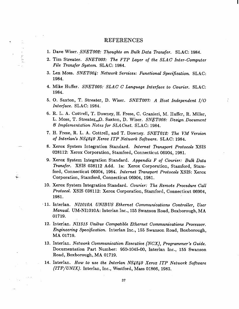
REFERENCES
Dave Wiser.~SNETOOZ: Thoughts on Bulk Data Transfer. SLAC: 1984.
Tim Streater. SNETOOS: The FTP Layer of the SLAC Inter-Computer File Transfer System. SLAC: 1984.
Len Moss. SNET004: Network Services: Functional Specification. SLAC: 1984.
Mike Huffer. SNETOOS: SLAC C Language Interface to Courier. SLAC: 1984.
0. Saxton, T. Streater, D. Wiser. SNET007: A Host Independent I/O Interface. SLAC: 1984.
R. L. A. Cottrell, T. Downey, H. Frese, C. Granieri, M. Huffer, R. Miller, L. Moss, T. Streater,Q. Saxton, D. Wiser. SNETOO8: Design Document B Implementation Notes for SLACnet. SLAC: 1984.
H. Frese, R. L. A. Cottrell, and T. Downey. SNET012: The VM Version of Interlan’s NS4240 Xerox ITP Network Software. SLAC: 1984.
Xerox System Integration Standard. Internet Transport Protocols XSIS 028112: Xerox Corporation, Stamford, Connecticut 06904, 1981.
Xerox System Integration Standard. Appendix F of Courier: Bulk Data Transfer. XSIS 038112 Add. la: Xerox Corporation, Stamford, Stam- ford, Connecticut 06904, 1984. Internet Transport Protocols XSIS: Xerox Corporation, Stamford, Connecticut 06904, 1981.
Xerox System Integration Standard. Courier: The Remote Procedure Call Protocol. XSIS 038112: Xerox Corporation, Stamford, Connecticut 06904, 1981.
Interlan. NIlOlOA UNIBUS Ethernet Communications Controller, User Manual. UM-NIlOlOA: Interlan Inc., 155 Swanson Road, Boxborough, MA 01719.
Interlan. NIl515 Unibus Compatible Ethernet Communications Processor. Engineering Specification. Interlan Inc., 155 Swanson Road, Boxborough, MA 01719.
Interlan. Network Communication Executive (NCX), Programmer’s Guide. Documentation Part Number: 950-1045-00, Interlan Inc., 155 Swanson Road, Boxborough, MA 01719.
Interlan. How to use the Interlan NS4,?40 Xerox ITP Network Software (ITP/~~Nx). I t 1 n er an, Inc., Westford, Mass 01866, 1983.
37
15. IBM. CMS Command and Macro Reference. SC19-6209-2: IBM 1983.
16. IBM. CP Command Reference for General Users. SC19-6211-2: IBM 1983.
.- 17. IBM. 7170 Device Attachment Control Unit General Information Manual. GA24-4022: IBM 1984.
18. IBM. VM,,SP System Programmer’s Guide SC19-6203-2: IBM 1983.
19. IBM. IBM VM/SP Operator’s Guide. SC19-6202-o: IBM 1980.
20. IBM. VM/SP System Product Interpreter User’s Guide. SC24-5238-O: IBM 1983.
21. Bridge Communications Inc. Ethernet System Product Line Overview. Document Number: 09-0001-02, Bridge Communications Inc., 2081 Stierlin Rd., Mountain View, CA 94043.
22. DEC. VAX/VA&M _eszage Utility Reference Manual. Order Number: AA- Z422A-TE, Digital Equipment Corporation, Maynard, MA.
23. DEC. Programming in C. Order Number: AA-LS’IOB-TE, Digital Equip- ment Corporation, Maynard, MA.
24. DEC, Intel, Xerox. The Ethernet, A Local Area Network, Data Link Layer and Physical Specifications, Version 2. Digital Equipment Corporation, Maynard, MA. Intel Corporation, Santa Clara, CA. Xerox Corporation, Stamford, CT. 1982.
=. 25. International Standards Organization. ISO: DP7498: Reference Model for
Open Systems Interconnection. ANSI, 1430 Broadway, New York, N.Y. 10018.
26. IEEE. Carrier Sense Multiple Access with Collision Detection (CSMA/CD). ANSI/IEEE Std 802.3-1985: The Institute of Electrical and Electronic En- gineers, Inc, 345 East 47th Street, New York, NY 10017. 1985.
27. ARPA. Internet Protocol Transition Workbook. Network Information Cen- ter, SRI International, Menlo Park, CA 94025. 1982.
28. D. Dewitt, L. H. Landweber, and M. S. Solomon. WISCNET - Protocol Implementation in a Virtual Machine Environment
29. File Transfer Protocol Implementers Group. A Network Independent File Transfer Protocol. Data Communications Protocols Unit, NPL, Tedding- ton, Middlesex TWll OLW, U.K. 1981.
30. M. J. Carmody. Waterloo C for VM/SP CMS User’s Guide. Computer System Group, University of Waterloo, 158 University Avenue, Waterloo, Ontario, Canada N2L 3E9.
38

31. Statistical Analysis System. SAS User’s Guide: Basics. SAS Institute, Inc., Box 8000, Cary, NC 27511, 1982.
- -+
39