SLAB SECTION SECTION THRU CONSTRUCTION...
2
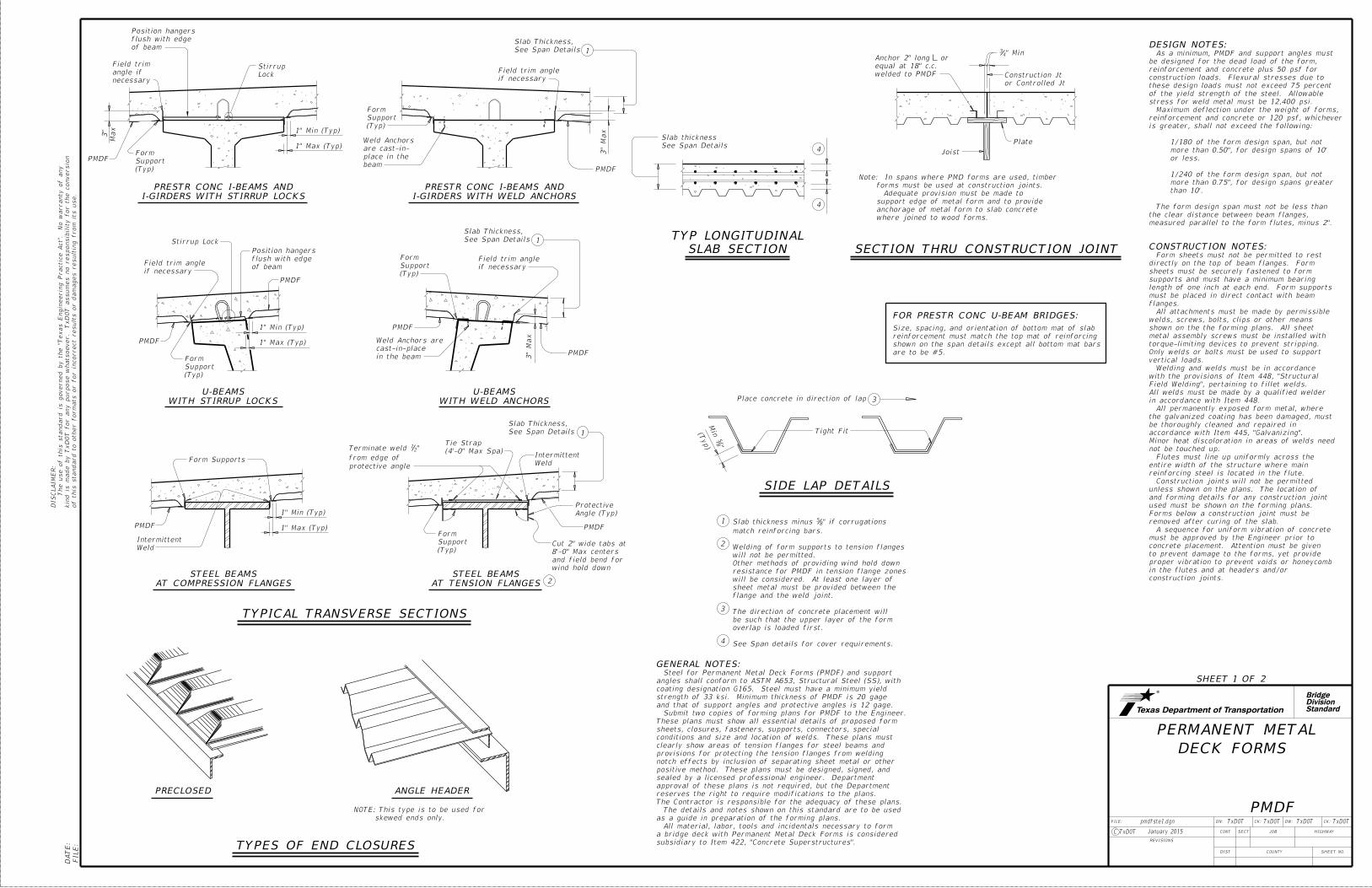
Standard Division Bridge o f t hi s s t a nda r d t o o t he r f o r ma t s o r f o r i n c o rr ec t r e s u lt s o r da ma g e s r e s u lti ng fr o m it s u s e . k i nd i s ma de by TxDOT f o r a ny pu r po s e wha t s o e v e r . TxDOT a ss u me s no r e s pon s i b ilit y f o r t he c onv e r s i on The u s e o f t hi s s t a nda r d i s gov e r n e d by t he " Te xa s Eng i n ee r i ng Pr ac ti ce Ac t " . No wa rr a n t y o f a ny DI SCL AI MER: FI LE: DATE: DN: CK: DW: CK: FILE: JOB COUNTY SECT DIST REVISIONS TxDOT TxDOT TxDOT TxDOT HIGHWAY SHEET NO. C TxDOT CONT pmdfste1.dgn January 2015 DECK FORMS PERMANENT METAL PMDF SHEET 1 OF 2 " Min 4 3 Plate Joist Place concrete in direction of lap See Span Details Slab thickness or Controlled Jt Construction Jt SECTION THRU CONSTRUCTION JOINT 3 welded to PMDF equal at 18" c.c. Anchor 2" long or Stirrup Lock in the beam cast-in-place Weld Anchors are PMDF PMDF if necessary Field trim angle of beam flush with edge Position hangers See Span Details Slab Thickness, 1 PMDF 3" Ma x 1" Min (Typ) 1" Max (Typ) if necessary Field trim angle 4 4 PMDF (Typ) Support Form (Typ) Support Form FOR PRESTR CONC U-BEAM BRIDGES: WITH STIRRUP LOCKS U-BEAMS WITH WELD ANCHORS U-BEAMS where joined to wood forms. anchorage of metal form to slab concrete support edge of metal form and to provide Adequate provision must be made to forms must be used at construction joints. Note: In spans where PMD forms are used, timber DESIGN NOTES: CONSTRUCTION NOTES: construction joints. in the flutes and at headers and/or proper vibration to prevent voids or honeycomb to prevent damage to the forms, yet provide concrete placement. Attention must be given must be approved by the Engineer prior to A sequence for uniform vibration of concrete removed after curing of the slab. Forms below a construction joint must be used must be shown on the forming plans. and forming details for any construction joint unless shown on the plans. The location of Construction joints will not be permitted reinforcing steel is located in the flute. entire width of the structure where main Flutes must line up uniformly across the not be touched up. Minor heat discoloration in areas of welds need accordance with Item 445, "Galvanizing". be thoroughly cleaned and repaired in the galvanized coating has been damaged, must All permanently exposed form metal, where in accordance with Item 448. All welds must be made by a qualified welder Field Welding", pertaining to fillet welds. with the provisions of Item 448, "Structural Welding and welds must be in accordance vertical loads. Only welds or bolts must be used to support torque-limiting devices to prevent stripping. metal assembly screws must be installed with shown on the the forming plans. All sheet welds, screws, bolts, clips or other means All attachments must be made by permissible flanges. must be placed in direct contact with beam length of one inch at each end. Form supports supports and must have a minimum bearing sheets must be securely fastened to form directly on the top of beam flanges. Form Form sheets must not be permitted to rest measured parallel to the form flutes, minus 2". the clear distance between beam flanges, The form design span must not be less than than 10'. more than 0.75", for design spans greater 1/240 of the form design span, but not or less. more than 0.50", for design spans of 10' 1/180 of the form design span, but not is greater, shall not exceed the following: reinforcement and concrete or 120 psf, whichever Maximum deflection under the weight of forms, stress for weld metal must be 12,400 psi. of the yield strength of the steel. Allowable these design loads must not exceed 75 percent construction loads. Flexural stresses due to reinforcement and concrete plus 50 psf for be designed for the dead load of the form, As a minimum, PMDF and support angles must skewed ends only. NOTE: This type is to be used for Tight Fit ( Typ ) " 8 5 Mi n PRECLOSED ANGLE HEADER TYPES OF END CLOSURES SIDE LAP DETAILS Form Supports PMDF PMDF GENERAL NOTES: Weld Intermittent TYPICAL TRANSVERSE SECTIONS 1" Min (Typ) 1" Max (Typ) 1 2 3 Weld Intermittent 2 See Span Details Slab Thickness, 1 See Span details for cover requirements. overlap is loaded first. be such that the upper layer of the form The direction of concrete placement will flange and the weld joint. sheet metal must be provided between the will be considered. At least one layer of resistance for PMDF in tension flange zones Other methods of providing wind hold down will not be permitted. Welding of form supports to tension flanges match reinforcing bars. " if corrugations 8 5 Slab thickness minus 4 (Typ) Support Form (4'-0" Max Spa) Tie Strap wind hold down and field bend for 8'-0" Max centers Cut 2" wide tabs at Angle (Typ) Protective protective angle from edge of " 2 1 Terminate weld AT COMPRESSION FLANGES STEEL BEAMS AT TENSION FLANGES STEEL BEAMS subsidiary to Item 422, "Concrete Superstructures". a bridge deck with Permanent Metal Deck Forms is considered All material, labor, tools and incidentals necessary to form as a guide in preparation of the forming plans. The details and notes shown on this standard are to be used The Contractor is responsible for the adequacy of these plans. reserves the right to require modifications to the plans. approval of these plans is not required, but the Department sealed by a licensed professional engineer. Department positive method. These plans must be designed, signed, and notch effects by inclusion of separating sheet metal or other provisions for protecting the tension flanges from welding clearly show areas of tension flanges for steel beams and conditions and size and location of welds. These plans must sheets, closures, fasteners, supports, connectors, special These plans must show all essential details of proposed form Submit two copies of forming plans for PMDF to the Engineer. and that of support angles and protective angles is 12 gage. strength of 33 ksi. Minimum thickness of PMDF is 20 gage coating designation G165. Steel must have a minimum yield angles shall conform to ASTM A653, Structural Steel (SS), with Steel for Permanent Metal Deck Forms (PMDF) and support are to be #5. shown on the span details except all bottom mat bars reinforcement must match the top mat of reinforcing Size, spacing, and orientation of bottom mat of slab necessary angle if Field trim 3" Ma x PMDF (Typ) Support Form 1" Min (Typ) 1" Max (Typ) I-GIRDERS WITH STIRRUP LOCKS PRESTR CONC I-BEAMS AND of beam flush with edge Position hangers Lock Stirrup beam place in the are cast-in- Weld Anchors (Typ) Support Form See Span Details Slab Thickness, 1 3" Ma x PMDF if necessary Field trim angle SLAB SECTION TYP LONGITUDINAL I-GIRDERS WITH WELD ANCHORS PRESTR CONC I-BEAMS AND
Transcript of SLAB SECTION SECTION THRU CONSTRUCTION...
StandardDivisionBridge
of this standard to other for
mats or for in
correct results or da
mages resultin
g fro
m its use.
kin
d is
made by Tx
DO
T for any purpose
whatsoever. Tx
DO
T assu
mes no responsibilit
y for the conversio
n
The use of this standard is governed by the "T
exas E
ngin
eerin
g Practic
e
Act".
No
warranty of any
DIS
CL
AI
ME
R:
FILE:
DA
TE:
DN: CK: DW: CK:FILE:
JOB
COUNTY
SECT
DIST
REVISIONS
TxDOT TxDOT TxDOT TxDOT
HIGHWAY
SHEET NO.
C TxDOT
CONT
pmdfste1.dgn
January 2015
DECK FORMS
PERMANENT METAL
PMDF
SHEET 1 OF 2
" Min43
Plate
Joist
Place concrete in direction of lap
See Span Details
Slab thickness
or Controlled Jt
Construction Jt
SECTION THRU CONSTRUCTION JOINT
3
welded to PMDF
equal at 18" c.c.
Anchor 2" long or
Stirrup Lock
in the beam
cast-in-place
Weld Anchors are
PMDF
PMDF
if necessary
Field trim angle
of beam
flush with edge
Position hangers
See Span Details
Slab Thickness,
1
PMDF
3"
Max
1" Min (Typ)
1" Max (Typ)
if necessary
Field trim angle
4
4
PMDF
(Typ)
Support
Form
(Typ)
Support
Form
FOR PRESTR CONC U-BEAM BRIDGES:
WITH STIRRUP LOCKS
U-BEAMS
WITH WELD ANCHORS
U-BEAMS
where joined to wood forms.
anchorage of metal form to slab concrete
support edge of metal form and to provide
Adequate provision must be made to
forms must be used at construction joints.
Note: In spans where PMD forms are used, timber
DESIGN NOTES:
CONSTRUCTION NOTES:
construction joints.
in the flutes and at headers and/or
proper vibration to prevent voids or honeycomb
to prevent damage to the forms, yet provide
concrete placement. Attention must be given
must be approved by the Engineer prior to
A sequence for uniform vibration of concrete
removed after curing of the slab.
Forms below a construction joint must be
used must be shown on the forming plans.
and forming details for any construction joint
unless shown on the plans. The location of
Construction joints will not be permitted
reinforcing steel is located in the flute.
entire width of the structure where main
Flutes must line up uniformly across the
not be touched up.
Minor heat discoloration in areas of welds need
accordance with Item 445, "Galvanizing".
be thoroughly cleaned and repaired in
the galvanized coating has been damaged, must
All permanently exposed form metal, where
in accordance with Item 448.
All welds must be made by a qualified welder
Field Welding", pertaining to fillet welds.
with the provisions of Item 448, "Structural
Welding and welds must be in accordance
vertical loads.
Only welds or bolts must be used to support
torque-limiting devices to prevent stripping.
metal assembly screws must be installed with
shown on the the forming plans. All sheet
welds, screws, bolts, clips or other means
All attachments must be made by permissible
flanges.
must be placed in direct contact with beam
length of one inch at each end. Form supports
supports and must have a minimum bearing
sheets must be securely fastened to form
directly on the top of beam flanges. Form
Form sheets must not be permitted to rest
measured parallel to the form flutes, minus 2".
the clear distance between beam flanges,
The form design span must not be less than
than 10'.
more than 0.75", for design spans greater
1/240 of the form design span, but not
or less.
more than 0.50", for design spans of 10'
1/180 of the form design span, but not
is greater, shall not exceed the following:
reinforcement and concrete or 120 psf, whichever
Maximum deflection under the weight of forms,
stress for weld metal must be 12,400 psi.
of the yield strength of the steel. Allowable
these design loads must not exceed 75 percent
construction loads. Flexural stresses due to
reinforcement and concrete plus 50 psf for
be designed for the dead load of the form,
As a minimum, PMDF and support angles must
skewed ends only.
NOTE: This type is to be used for
Tight Fit(Typ) "8
5
Min
PRECLOSED ANGLE HEADER
TYPES OF END CLOSURES
SIDE LAP DETAILS
Form Supports
PMDF PMDF
GENERAL NOTES:
Weld
Intermittent
TYPICAL TRANSVERSE SECTIONS
1" Min (Typ)
1" Max (Typ)1
2
3
Weld
Intermittent
2
See Span Details
Slab Thickness,
1
See Span details for cover requirements.
overlap is loaded first.
be such that the upper layer of the form
The direction of concrete placement will
flange and the weld joint.
sheet metal must be provided between the
will be considered. At least one layer of
resistance for PMDF in tension flange zones
Other methods of providing wind hold down
will not be permitted.
Welding of form supports to tension flanges
match reinforcing bars.
" if corrugations85Slab thickness minus
4
(Typ)
Support
Form
(4'-0" Max Spa)
Tie Strap
wind hold down
and field bend for
8'-0" Max centers
Cut 2" wide tabs at
Angle (Typ)
Protective
protective angle
from edge of
"21Terminate weld
AT COMPRESSION FLANGES
STEEL BEAMS
AT TENSION FLANGES
STEEL BEAMS
subsidiary to Item 422, "Concrete Superstructures".
a bridge deck with Permanent Metal Deck Forms is considered
All material, labor, tools and incidentals necessary to form
as a guide in preparation of the forming plans.
The details and notes shown on this standard are to be used
The Contractor is responsible for the adequacy of these plans.
reserves the right to require modifications to the plans.
approval of these plans is not required, but the Department
sealed by a licensed professional engineer. Department
positive method. These plans must be designed, signed, and
notch effects by inclusion of separating sheet metal or other
provisions for protecting the tension flanges from welding
clearly show areas of tension flanges for steel beams and
conditions and size and location of welds. These plans must
sheets, closures, fasteners, supports, connectors, special
These plans must show all essential details of proposed form
Submit two copies of forming plans for PMDF to the Engineer.
and that of support angles and protective angles is 12 gage.
strength of 33 ksi. Minimum thickness of PMDF is 20 gage
coating designation G165. Steel must have a minimum yield
angles shall conform to ASTM A653, Structural Steel (SS), with
Steel for Permanent Metal Deck Forms (PMDF) and support
are to be #5.
shown on the span details except all bottom mat bars
reinforcement must match the top mat of reinforcing
Size, spacing, and orientation of bottom mat of slab
necessary
angle if
Field trim
3"
Max
PMDF
(Typ)
Support
Form
1" Min (Typ)
1" Max (Typ)
I-GIRDERS WITH STIRRUP LOCKS
PRESTR CONC I-BEAMS AND
of beam
flush with edge
Position hangers
Lock
Stirrup
beam
place in the
are cast-in-
Weld Anchors
(Typ)
Support
Form
See Span Details
Slab Thickness,
1
3"
Max
PMDF
if necessary
Field trim angle
SLAB SECTION
TYP LONGITUDINAL
I-GIRDERS WITH WELD ANCHORS
PRESTR CONC I-BEAMS AND

StandardDivisionBridge
of this standard to other for
mats or for in
correct results or da
mages resultin
g fro
m its use.
kin
d is
made by Tx
DO
T for any purpose
whatsoever. Tx
DO
T assu
mes no responsibilit
y for the conversio
n
The use of this standard is governed by the "T
exas E
ngin
eerin
g Practic
e
Act".
No
warranty of any
DIS
CL
AI
ME
R:
FILE:
DA
TE:
DN: CK: DW: CK:FILE:
JOB
COUNTY
SECT
DIST
REVISIONS
TxDOT TxDOT TxDOT TxDOT
HIGHWAY
SHEET NO.
C TxDOT
CONT
pmdfste1.dgn
January 2015
DECK FORMS
PERMANENT METAL
PMDF
SHEET 2 OF 2
See Detail "A"
Slab thickness
See Span Details
L BrgC
CTop of Bm
elsewhere in plans
Perpendicular to Joint
1
removable form
Permanent or
1'-3"
See Detail "A"
6"
U-Beam
Top of
Slab thickness
See Span Details
1C
FOR U-BEAMS
AT THICKENED SLAB END
forms
or removable
PermanentPMDF
Support
Form
with beam flange
to ensure uniform contact
beam flange as necessary
Secure Form Support to
SECTION A-A
L Deck Jt
L Deck Jt
Dimension shown
Perpendicular to Joint
See Span Details
I-GIRDERS AND STEEL BEAMS
FOR PRESTRESSED I-BEAMS,
AT THICKENED SLAB END
Slab thickness
See Span Details
See Detail "A"
Weld
L BentC
1
End Diaphragm
form
removable
Permanent or
Slab thickness
See Span Details
C
1
forms
or removable
Permanent
Bent Cap
Inverted Tee
WITHOUT THICKENED SLAB END
INV TEE STEM FOR CONC BEAMS
AT SLAB OVER ABUT BKWL OR
WITHOUT THICKENED SLAB END
FOR STEEL BEAMS
AT SLAB OVER INV TEE STEM
Top of BmTop of Bm
2"
2"
Varia
ble
1"
Min
Lap Joint
Permissible
as required
Bent Plate, size
18" c.c. Max
Fasteners at
DETAIL "A"
16 Gage (Min)
at L Brg ~ See Span Details
Top of Slab to Top of Beam
See Detail "B"
Slab thickness
See Span Details
C
L Brg
C
1
End Diaphragm
at L Brg ~ See Span Details
Top of Slab to Top of Beam
AND STEEL BEAMS
FOR PRESTRESSED I-BEAMS
AT CONC END DIAPHRAGM
Top of Bm
Weld
See Detail "A"
C
Slab thickness
See Span Detailsrequired
Bent PL ~ size as
1" Min
1
form
removable
Permanent or
End Diaphragm
WITHOUT THICKENED SLAB END
FOR STEEL BEAMS
AT END DIAPHRAGM
L Deck Jt
Top of Bm
1"
Min
1"
Max
size as required
Bent PL or L ~
cut on skew
where form is
closure required
PMD Form, end
1
5
match reinforcing bars
" if corrugations85Slab thickness minus
18" c.c. Max
Fasteners at
DETAIL "B"
in diaphragm
Anchors cast
shall be 40 ksi
Minimum yield stress of 12 Gage bars
DETAILS AT ENDS OF BEAMS
forms
or removable
Permanent
L Deck Jt
C
Angle
Support
PMDF
L Existing Beam
Compression
Flange only
163 2"
"2
1
"21
"213
Reinf Bars
Existing
Conc Slab
Existing
WIDENING DETAILS
SHOWING STEEL BEAMS
4'-0" Max
12 Gage at
2" Flat Bar
Compression Flange
Flat Bar 12 Gage ~
Tension Flange
Protective angle ~
5
5
for I-Girders or Steel Beams.
Showing I-Beam block-out. No block-out
C
A
A
Conc Slab
Existing
Reinf Bars
Existing"2
1
"213
Angle
Support
PMDF
"2
1
163 2"
at 4'-0" Max
2" Flat Bar 12 Gage
5
12 Gage
Flat Bar
5
for break line location
See Span Details
C
Prestr I-Girder
L Existing
I-BEAMS, I-GIRDERS AND U-BEAMS
SHOWING PRESTRESSED CONCRETE