
Slab and Screed Guidance - Michigan€¦ · Slab and Screed Guidance The purpose of this guidance...
12
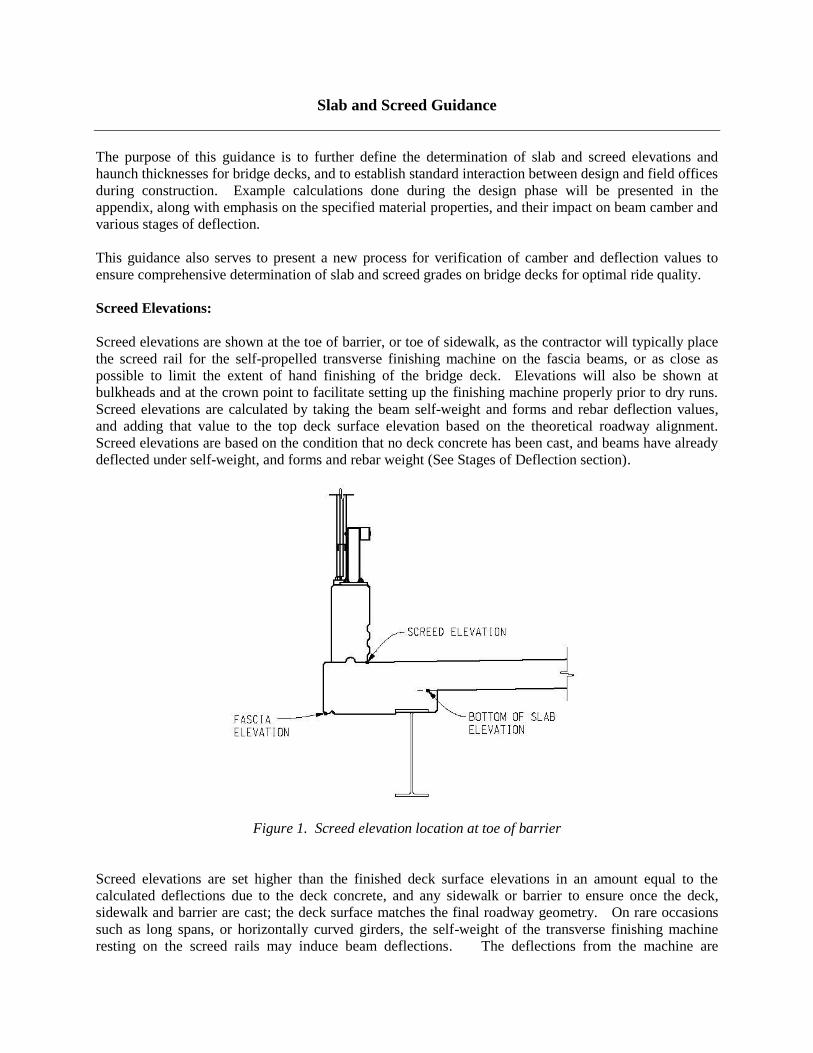
Slab and Screed Guidance The purpose of this guidance is to further define the determination of slab and screed elevations and haunch thicknesses for bridge decks, and to establish standard interaction between design and field offices during construction. Example calculations done during the design phase will be presented in the appendix, along with emphasis on the specified material properties, and their impact on beam camber and various stages of deflection. This guidance also serves to present a new process for verification of camber and deflection values to ensure comprehensive determination of slab and screed grades on bridge decks for optimal ride quality. Screed Elevations: Screed elevations are shown at the toe of barrier, or toe of sidewalk, as the contractor will typically place the screed rail for the self-propelled transverse finishing machine on the fascia beams, or as close as possible to limit the extent of hand finishing of the bridge deck. Elevations will also be shown at bulkheads and at the crown point to facilitate setting up the finishing machine properly prior to dry runs. Screed elevations are calculated by taking the beam self-weight and forms and rebar deflection values, and adding that value to the top deck surface elevation based on the theoretical roadway alignment. Screed elevations are based on the condition that no deck concrete has been cast, and beams have already deflected under self-weight, and forms and rebar weight (See Stages of Deflection section). Figure 1. Screed elevation location at toe of barrier Screed elevations are set higher than the finished deck surface elevations in an amount equal to the calculated deflections due to the deck concrete, and any sidewalk or barrier to ensure once the deck, sidewalk and barrier are cast; the deck surface matches the final roadway geometry. On rare occasions such as long spans, or horizontally curved girders, the self-weight of the transverse finishing machine resting on the screed rails may induce beam deflections. The deflections from the machine are
Transcript of Slab and Screed Guidance - Michigan€¦ · Slab and Screed Guidance The purpose of this guidance...
Slab and Screed Guidance
The purpose of this guidance is to further define the determination of slab and screed elevations and
haunch thicknesses for bridge decks, and to establish standard interaction between design and field offices
during construction. Example calculations done during the design phase will be presented in the
appendix, along with emphasis on the specified material properties, and their impact on beam camber and
various stages of deflection.
This guidance also serves to present a new process for verification of camber and deflection values to
ensure comprehensive determination of slab and screed grades on bridge decks for optimal ride quality.
Screed Elevations:
Screed elevations are shown at the toe of barrier, or toe of sidewalk, as the contractor will typically place
the screed rail for the self-propelled transverse finishing machine on the fascia beams, or as close as
possible to limit the extent of hand finishing of the bridge deck. Elevations will also be shown at
bulkheads and at the crown point to facilitate setting up the finishing machine properly prior to dry runs.
Screed elevations are calculated by taking the beam self-weight and forms and rebar deflection values,
and adding that value to the top deck surface elevation based on the theoretical roadway alignment.
Screed elevations are based on the condition that no deck concrete has been cast, and beams have already
deflected under self-weight, and forms and rebar weight (See Stages of Deflection section).
Figure 1. Screed elevation location at toe of barrier
Screed elevations are set higher than the finished deck surface elevations in an amount equal to the
calculated deflections due to the deck concrete, and any sidewalk or barrier to ensure once the deck,
sidewalk and barrier are cast; the deck surface matches the final roadway geometry. On rare occasions
such as long spans, or horizontally curved girders, the self-weight of the transverse finishing machine
resting on the screed rails may induce beam deflections. The deflections from the machine are
insignificant when compared to the deflections caused by the plastic concrete; however, deflection of the
screed rail and finishing machine itself may need to be accounted for.
Standard specifications subsection 706.03.A.2 requires the actual screed rail grades to be within 1/16 inch
of the screed grades shown on the plans. The contractor is responsible to adjust the rail grades at their
supports or to install tighter support spacing to ensure deflection of the rails (between supports) due to the
weight of the self-propelled transverse screed machine does not exceed 1/16 inch.
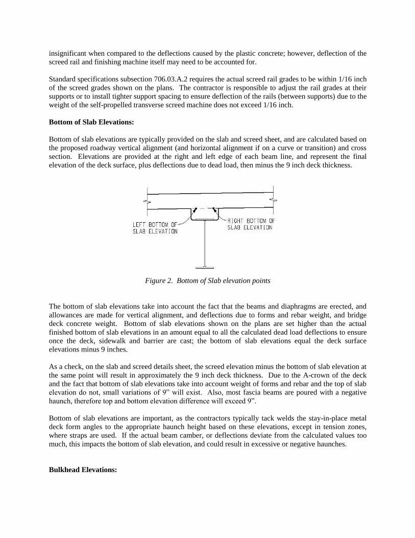
Bottom of Slab Elevations:
Bottom of slab elevations are typically provided on the slab and screed sheet, and are calculated based on
the proposed roadway vertical alignment (and horizontal alignment if on a curve or transition) and cross
section. Elevations are provided at the right and left edge of each beam line, and represent the final
elevation of the deck surface, plus deflections due to dead load, then minus the 9 inch deck thickness.
Figure 2. Bottom of Slab elevation points
The bottom of slab elevations take into account the fact that the beams and diaphragms are erected, and
allowances are made for vertical alignment, and deflections due to forms and rebar weight, and bridge
deck concrete weight. Bottom of slab elevations shown on the plans are set higher than the actual
finished bottom of slab elevations in an amount equal to all the calculated dead load deflections to ensure
once the deck, sidewalk and barrier are cast; the bottom of slab elevations equal the deck surface
elevations minus 9 inches.
As a check, on the slab and screed details sheet, the screed elevation minus the bottom of slab elevation at
the same point will result in approximately the 9 inch deck thickness. Due to the A-crown of the deck
and the fact that bottom of slab elevations take into account weight of forms and rebar and the top of slab
elevation do not, small variations of 9” will exist. Also, most fascia beams are poured with a negative
haunch, therefore top and bottom elevation difference will exceed 9”.
Bottom of slab elevations are important, as the contractors typically tack welds the stay-in-place metal
deck form angles to the appropriate haunch height based on these elevations, except in tension zones,
where straps are used. If the actual beam camber, or deflections deviate from the calculated values too
much, this impacts the bottom of slab elevation, and could result in excessive or negative haunches.
Bulkhead Elevations:

Bulkhead elevations are deck surface elevations transverse to beam lines at each abutment, and when
crossing expansion or construction joints. The intent is to provide the contractor with an elevation to
place expansion joint rails, or metal bulkheads for construction joints when following the deck pour
sequence as shown on the plans. Similar to bottom of slab elevations, bulkhead elevations take into
account vertical alignment, and deflections (there is no deflection at the abutments or piers) due to beam
self-weight, forms and rebar, and bridge deck concrete weight. Bulkheads may be eliminated when
combining deck pours. Changes to the pour sequence or the combining of deck pours must be approved
by the design engineer.
Haunches:
Haunches are determined based on the fact that the final deflected shape of the beam will not exactly
match the proposed roadway vertical alignment. Designers calculate haunch thicknesses based on the
difference between the bottom of slab elevation, and the top of beam elevations. On new structures or
superstructure replacements, designers will assume a minimum haunch thickness to afford flexibility in
the field if bottom of slab elevations require adjustment. On deck replacements, designers are at the
mercy of existing beam conditions and must calculate haunches on known conditions and calculated
deflections. The beam elevations are determined based on the elevations of points of support, and the in-
span deflections. Haunch thicknesses are variable along the length of the beam to accommodate the
difference between roadway geometry, and structural deflections of the beams. The goal being
satisfactory ride quality transitioning from road to bridge.
For structures on sag vertical curves with ideal beam camber, the haunch will typically be maximum at
the ends the span, and minimum at midspan. For structures on crest vertical curves, the haunch may be
minimum at the ends of the span, and maximum at midspan. Designers try to coordinate the beam
camber to match the crested roadway when possible to offer consistent haunch grades. The Michigan
Bridge Design Manual, section 7.02.19C directs designers to use a uniform 1” thick haunch for steel
beams, and a minimum 2” thick haunch for prestressed concrete beams.
Haunch thicknesses are also variable across the cross section, given the crown, or superelevation of the
roadway surface, or the skew of the bridge.
Beam Camber:
Beams are positively or negatively cambered to compensate for dead load and live load deflections to
match the proposed roadway vertical alignment. There are several stages of dead load deflection that are
taken into account as described in the Stages of Deflection section, and the camber ordinates are
determined based on the magnitude of these deflections.
There are differences in control of camber and deflections between steel beams and prestressed concrete
beams as described below.
Steel Beams:
Camber ordinates on steel beams are developed based on the vertical alignment going across the bridge,
and the calculated dead load and live load deflections. It is undesirable to induce negative camber at
service loads, as this could impact the vertical underclearance, so live load has to be taken into account.
All of the stages of dead load deflection, plus the live load deflection are summated to determine the
maximum required midspan camber ordinate value. Additional camber may also be required for
geometry.
MDOT Bridge Design Manual section 7.02.06 requires a compensating camber to be designed into the
beams where dead load deflection or vertical curve offset are greater than ¼”. This may include a
negative camber for portions of beams on continuous spans to ensure uniform haunch depths, and bottom
of slab elevations such that the sum of all dead load deflections results in the deck top surface matching
the proposed roadway vertical alignment as close as practicable.
During fabrication, camber is easier to control for steel beams than for prestressed concrete beams. For
built up steel plate girder, fabricators have two options to fabricate beams to the specified camber:
• The web plate can be cut in a parabolic shape to match the camber ordinates shown on the
contract plans, and the top and bottom flange plates are then welded to the shaped web plate.
• The web plate can be cut straight, the top and bottom flanges welded on, and the entire beam
heated as to allow manipulation to the desired camber. The beam is then allowed to cool while
being restrained to the required position as to lock in the cambered shape.
For rolled wide flange shapes, fabricators heat the beams is the same fashion as the second option for
built up plate girders to achieve the required camber.
As a result, the maximum camber for steel beams is a function of fabricated geometry and greater control
of camber can be achieved.
For deck replacement projects on steel beam superstructures, the slab and screed elevations in the plans
will be based on the beams rebounding to their original elevation prior to weight of the concrete deck.
This does not always occur, and permanent camber loss can result due to years of dead and live load
deflection during service. It is always important to survey the tops of the beams at the same intervals as
shown on the slab and screed sheets, and provide this information to the designer for review, and to make
adjustments to grades if necessary.
Prestressed Concrete Beams:
Similar to steel beams, camber is also required for prestressed concrete beams; however, the amount of
upward deflection is a function of the prestress force, the eccentricity of the prestressing strands to the
neutral axis of the beam, the beam shape, and properties of the concrete mix. To understand prestressed
beam camber, and how changes to the specified design compressive strength of the concrete impact
camber, please see Appendix A for detailed calculations.
Designers specify a minimum compressive strength required at prestress strand release based on
acceptable levels of stress in the beams, and this value is used in the deflection calculations. Fabricators
often add accelerators and water reducers to increase the short-term strength gain in the concrete mix, to
ensure the prestressing beds can be turned around in a specified time needed for production. Although
fabricators are required to meet camber tolerances per Table 708-1 of the standard specifications, the
result is the actual prestress beam deflections diverging from the theoretical deflection calculated during
design due to the higher compressive strength.
Stages of Deflection:
The slab and screed, and bulkhead elevations on the project plans are calculated to ensure the final deck
position closely matches the design roadway alignment taking into account camber, and all stages of

superstructure deflection. To accomplish this, the calculations assume that a beam lying on its side is
fully cambered, as shown in Figure 3.
The camber ordinates shown in Figure 3 will be shown on the project plans for steel girders to direct the
fabricator what camber is required.
Maximum midspan camber taking into account beam dead load deflection will be shown on the plans for
prestressed concrete beams.
Figure 3. Beam lying on its side
The first step in determining the slab and screed grades is calculating the reduction in camber due to the
girder self-weight. When a girder is supported at points of bearing, either on a pier or abutment, the
girder will deflect under its own self-weight. At support points there will be no deflection. For simply
supported spans, maximum deflection will occur at midspan, and for continuous girders, maximum
downward deflection will occur at some point prior to midspan, and upward deflection in adjacent spans
is considered in the bridge deck pour sequence. Figure 4 shows a span supported at bearing points
deflecting under the girder self-weight load, which is designated as Δ1.
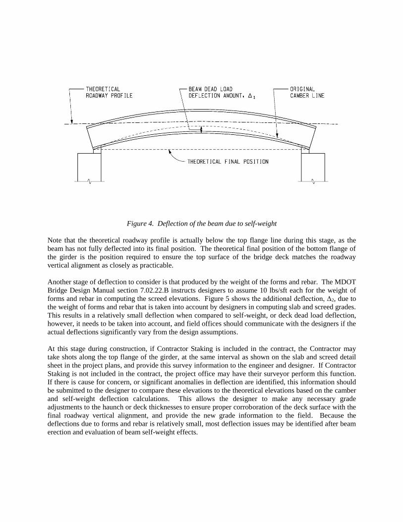
Figure 4. Deflection of the beam due to self-weight
Note that the theoretical roadway profile is actually below the top flange line during this stage, as the
beam has not fully deflected into its final position. The theoretical final position of the bottom flange of
the girder is the position required to ensure the top surface of the bridge deck matches the roadway
vertical alignment as closely as practicable.
Another stage of deflection to consider is that produced by the weight of the forms and rebar. The MDOT
Bridge Design Manual section 7.02.22.B instructs designers to assume 10 lbs/sft each for the weight of
forms and rebar in computing the screed elevations. Figure 5 shows the additional deflection, Δ2, due to
the weight of forms and rebar that is taken into account by designers in computing slab and screed grades.
This results in a relatively small deflection when compared to self-weight, or deck dead load deflection,
however, it needs to be taken into account, and field offices should communicate with the designers if the
actual deflections significantly vary from the design assumptions.
At this stage during construction, if Contractor Staking is included in the contract, the Contractor may
take shots along the top flange of the girder, at the same interval as shown on the slab and screed detail
sheet in the project plans, and provide this survey information to the engineer and designer. If Contractor
Staking is not included in the contract, the project office may have their surveyor perform this function.
If there is cause for concern, or significant anomalies in deflection are identified, this information should
be submitted to the designer to compare these elevations to the theoretical elevations based on the camber
and self-weight deflection calculations. This allows the designer to make any necessary grade
adjustments to the haunch or deck thicknesses to ensure proper corroboration of the deck surface with the
final roadway vertical alignment, and provide the new grade information to the field. Because the
deflections due to forms and rebar is relatively small, most deflection issues may be identified after beam
erection and evaluation of beam self-weight effects.

Figure 5. Deflection of the beam due to the weight of forms and rebar
Once the forms and rebar are set, the screed rails for the self-propelled transverse finishing machine
should be set on the fascia beams to either the elevations shown on the plans, or adjusted elevations based
on changes between the theoretical and actual camber and beam self-weight deflections. At this stage, a
dry run is to be conducted by the contractor to ensure proper deck thickness measurements from the
bottom of finishing machine to the top of the deck forms.
The most significant deflections of the beams occur under the wet load of concrete, prior to concrete cure,
and attainment of composite action. Figure 6 shows the deflection, Δ3 due to the weight of the deck
concrete. At this stage the beams should be very near their theoretical final position.
Figure 6. Deflection of the beam due to the weight of deck concrete

Once the bridge deck has been continuously wet cured for seven days per Standard Specifications
subsection 706.03.N, succeeding portions of the structure, such as sidewalk and bridge barrier railing may
be cast on the deck. Figure 7 shows the deflection, Δ4 due to the weight of sidewalk and barrier.
Figure 7. Deflection of the beam due to the weight of sidewalk or barrier
The value of Δ4 will be relatively small, as the moment of inertia used in the deflection calculation is now
that of the composite section of beam and concrete deck.
The slab and screed grades shown on the plans take into account the beam camber minus the sum of all
stages of construction deflection (Δ1 + Δ2 + Δ3 + Δ4) to obtain grades that result in the bridge deck surface
closely matching the theoretical roadway alignment upon completion of the sidewalk and barrier concrete
pours.
At this stage, any bumps in the bridge deck, or surface tolerances exceeding 1/8 inch over 10 feet must be
removed via grinding. This results in the removal of the densified floated finish portion of the bridge
deck, and can introduce micro-cracks into the deck structure, both of which are undesirable. Ensuring the
finished deck surface matches the final vertical roadway geometry as close as possible will help prevent
grinding on the finished bridge deck. This requires careful attention to detail on the actual beam camber
and deflections compared to what is shown on the plans and communication with the designer when
values do not correspond.
Staged Construction:
Staged construction on bridge projects presents a challenge for geometry control on the finished deck
surface.
On curved steel girder bridges constructed part width, there is a potential for the bridge deck not matching
at the stage line due to differential deflections from the difference in beam stiffness (due to length and
curvature) from beam to beam. This can be compensated by taking survey measurements on the tops of
the Stage 2 beams, and the Stage 1 bridge deck, and providing these elevations to the designer for review.
On prestressed side-by-side box beam bridges constructed part width, all the box beams may be fabricated
at the same time. The Stage 1 beams will be erected and experience full dead load deflection, while the
Stage 2 beams may experience camber growth due to the prestressing force eccentricity. This causes
issues during Stage 2 construction such as transverse post tensioning ducts not lining up, or potential
change in deck thickness at the stage line. If all the beams for a staged construction project are cast
together, the Stage 2 beams should be monitored for camber growth. The most significant camber growth
is a result of curing concrete and strength gain and occurs within the first 28 days after beam casting.
Any growth in camber should be communicated to the designer and adjustments made to the haunch
grades if necessary. Preloading the beams after erection may be necessary to align post tensioning ducts.
Contact the designer for assistance with prestressed side-by-side box beam bridge projects that are done
part width.
Recommended changes to current requirements:
MDOT Bridge Design Manual:
Section 7.01.09: Restricting the use of the 0.3% allowable lower limit for longitudinal grade to require
approval from the Bridge Design Supervisor. 0.5% should be the absolute minimum, and 1% should be
preferred.
Add the following paragraphs to section 7.02.22B:
In computing camber ordinates for prestressed concrete beams, the number and length of debonded
strands shall be taken into account.
Deflections due to sidewalk, barrier, brushblocks, utilities, and other non-structural attachments shall be
computed using the composite moment of inertia.
The following notes should be added to Chapter 8, and the Slab and Screed sheet:
• Create note 8.07.06:
ONCE BEAMS ARE ERECTED ON SUPPORTS, THE CONTRACTOR IS TO TAKE
SURVEY ELEVATIONS OF THE TOP OF BEAMS AT A MINIMUM, AT THE ENDS AND
MIDSPAN (OR POINT OF MAXIMUM DEFLECTION FOR CONTINUOUS GIRDERS)OF
EACH BEAM.. THE CONTRACTOR IS TO SUBMIT THE TOP OF BEAM ELEVATIONS
TO THE ENGINEER FOR REVIEW AND APPROVAL FIVE (5) BUSINESS DAYS PRIOR
TO FORMING THE BOTTOM OF SLAB, OR PAN DECKING INSTALLATION.
• Create note 8.07.07:
THE CALCULATED STAGES OF DEFLECTION ARE AS FOLLOWS:
BEAM DEAD LOAD = XX INCHES
FORMS AND REBAR = XX INCHES
DECK DEAD LOAD = XX INCHES
BARRIER AND SIDEWALK = XX INCHES
Appendix 1 – Sample camber and deflection calculations
Net beam camber upon release of the prestressing strands is given by the following expression:
−=i
Where:
i = Net camber at transfer
= Upward deflection due to prestressing
= Downward deflection due to girder self-weight

−+=
688
222L
IE
eP
IE
eLP
gc
i
gc
i
Where:
iP = Prestressing force immediately after transfer
cE = Elastic modulus of girder concrete at transfer
gI = Girder gross section moment of inertia
e = Prestressing strand eccentricity at midspan relative to the centroid of the girder gross
section
ee = Prestressing strand eccentricity at the end of the girder to the centroid of the girder gross
cross section. Debonding is neglected.
L = Girder length
= Distance from draping point to end of span
The above equation can be used for two point draped strands, and for straight strands, where the second
term is zero, since α is zero.
Camber is also dependent on the number and length of strands debonded, and as such, the reduction in
camber due to strand debonding is also taken into account.
The self-weight downward deflection equation is not unique to prestressed concrete beams. The
following equation can be used to calculate deflections for all standard beam types:
diaphragm
gc
g
IE
Lw+=
384
5 4
Where:
gw = Linearly distributed girder self-weight
diaphram = deflection due to midspan diaphragms
The theoretical elastic modulus of a concrete girder is a function of the compressive strength of the
concrete mix used, given by the following equation:
'5.1000,33 ccc fwE =
Where:
cw = Unit weight of concrete

'
cf = Specified compressive strength of the concrete
To illustrate this further, consider a 120 foot long MI 1800 prestressed girder, with an initial prestress
force of 1170 kips, with an eccentricity of 31 inches, and a required compressive strength at release of
5500 psi. Based on the required compressive strength at release:
ksipsiftlbEc 44965500)/150(000,33 5.13 ==
The camber of the beam taking into account the beam self-weight deflection is as follows:
( )in
inksi
ftinftftkip
inksi
ftinftinkipsi 22.3
700,624*4496*384
)/12()120)(/910.0(5
700,624*4496*8
/12*)120(*31*11704
24
4
22
=−=
That camber value is used by the designer to develop the slab and screed grades. If the compressive
strength of the concrete at release is 9000 psi, the difference is as follows:
ksipsiftlbEc 57519000)/150(000,33 5.13 ==
The revised camber of the beam taking into account the beam self-weight deflection is as follows:
( )in
inksi
ftinftftkip
inksi
ftinftinkipsi 52.2
700,624*5751*384
)/12()120)(/910.0(5
700,624*5751*8
/12*)120(*31*11704
24
4
22
=−=
This results in a 0.70 inch change in camber, which is significant in terms of changes to haunches or deck
thickness values to compensate. This demonstrates the importance of the field office taking shots on the
beams when they are on their supports, with only dead load deflection taken into account. At this time,
the designer may adjust the final bottom of slab grades, or screed elevations to accommodate changes
from the theoretical grades.


