SKP Engineering College - getmynotes.com · Design: Wireless networks allow for the design of...
277
Getmynotes.com S.K.P. Engineering College, Tiruvannamalai VIII SEM SKP Engineering College Tiruvannamalai – 606611 A Course Material on Wireless Networks By S.Baskaran Professor Electronics and Communication Engineering Department Electronics and Communciation Engineering Department 1 Wireless networks
Transcript of SKP Engineering College - getmynotes.com · Design: Wireless networks allow for the design of...
Getmynotes.com
S.K.P. Engineering College, Tiruvannamalai VIII SEM
SKP Engineering CollegeTiruvannamalai – 606611
A Course Material
on
Wireless Networks
By
S.Baskaran
Professor
Electronics and Communication Engineering Department
Electronics and Communciation Engineering Department 1 Wireless networks

Getmynotes.com
S.K.P. Engineering College, Tiruvannamalai VIII SEM
Quality Certificate
This is to Certify that the Electronic Study Material
Subject Code: EC6802
Subject Name:Wireless Networks
Year/Sem:IV/VIII
Being prepared by me and it meets the knowledge requirement of the University
curriculum.
Signature of the Author
Name: S.Baskaran
Designation: Professor
This is to certify that the course material being prepared by Dr.S.Baskaran is of the
adequate quality. He has referred more than five books and one among them is from
abroad author.
Signature of HD Signature of the Principal
Name: Mr.R.Saravanakumar Name: Dr.V.Subramania Bharathi
Seal: Seal:
Electronics and Communciation Engineering Department 2 Wireless networks

Getmynotes.com
S.K.P. Engineering College, Tiruvannamalai VIII SEM
EC6802 WIRELESS NETWORKS L T P C 3 0 0 3
OBJECTIVES:
To study about Wireless networks, protocol stack and standards.
To study about fundamentals of 3G Services, its protocols and applications.
To study about evolution of 4G Networks, its architecture and applications.
UNIT I WIRELESS LAN 9
Introduction-WLAN technologies: Infrared, UHF narrowband, spread spectrum -IEEE802.11: System architecture, protocol architecture, physical layer, MAC layer,802.11b, 802.11a – Hiper LAN: WATM, BRAN, HiperLAN2 – Bluetooth: Architecture,Radio Layer, Baseband layer, Link manager Protocol, security – IEEE802.16-WIMAX:Physical layer, MAC, Spectrum allocation for WIMAX
UNIT II MOBILE NETWORK LAYER 9
Introduction – Mobile IP: IP packet delivery, Agent discovery, tunneling andencapsulation, IPV6-Network layer in the internet- Mobile IP session initiation protocol –mobile ad-hoc network: Routing, Destination Sequence distance vector, Dynamicsource routing
UNIT III MOBILE TRANSPORT LAYER 9
TCP enhancements for wireless protocols – Traditional TCP: Congestion control, fastretransmit/fast recovery, Implications of mobility – Classical TCP improvements: IndirectTCP, Snooping TCP, Mobile TCP, Time out freezing, Selective retransmission,Transaction oriented TCP – TCP over 3G wireless networks.
UNIT IV WIRELESS WIDE AREA NETWORK 9
Overview of UTMS Terrestrial Radio access network-UMTS Core network Architecture:3G-MSC, 3G-SGSN, 3G-GGSN, SMS-GMSC/SMS-IWMSC, Firewall, DNS/DHCP-Highspeed Downlink packet access (HSDPA)- LTE network architecture and protocol.
UNIT V 4G NETWORKS 9
Electronics and Communciation Engineering Department 3 Wireless networks
Getmynotes.com
S.K.P. Engineering College, Tiruvannamalai VIII SEM
Introduction – 4G vision – 4G features and challenges – Applications of 4G – 4GTechnologies: Multicarrier Modulation, Smart antenna techniques, OFDM-MIMOsystems, Adaptive Modulation and coding with time slot scheduler, Cognitive Radio.
TOTAL: 45 PERIODS
OUTCOMES: Upon completion of the course, the students will be able to
Conversant with the latest 3G/4G and WiMAX networks and its architecture.
Design and implement wireless network environment for any application using latestwireless protocols and standards.
Implement different type of applications for smart phones and mobile devices withlatest network strategies.
TEXT BOOKS:
1.Jochen Schiller, ”Mobile Communications”, Second Edition, Pearson Education 2012.(Unit I,II,III)2.Vijay Garg , “Wireless Communications and networking”, First Edition, Elsevier
2007. (Unit IV,V)
REFERENCES:1. Erik Dahlman, Stefan Parkvall, Johan Skold and Per Beming, “3G Evolution
HSPA and LTE for Mobile Broadband”, Second Edition, Academic Press, 2008.2. Anurag Kumar, D.Manjunath, Joy kuri, “Wireless Networking”, First Edition,
Elsevier 2011.3. Simon Haykin , Michael Moher, David Koilpillai, “Modern Wireless Communications”
Electronics and Communciation Engineering Department 4 Wireless networks
Getmynotes.com
S.K.P. Engineering College, Tiruvannamalai VIII SEM
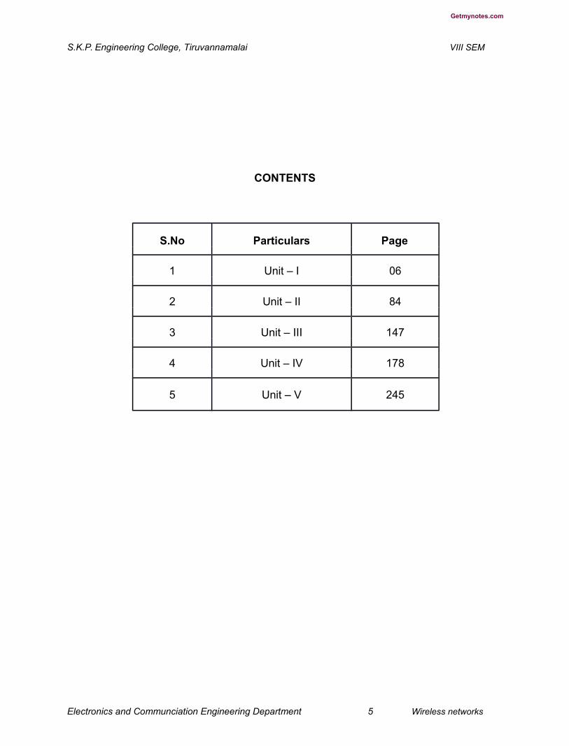
CONTENTS
S.No Particulars Page
1 Unit – I 06
2 Unit – II 84
3 Unit – III 147
4 Unit – IV 178
5 Unit – V 245
Electronics and Communciation Engineering Department 5 Wireless networks
Getmynotes.com
S.K.P. Engineering College, Tiruvannamalai VIII SEM
Unit - I
Wireless LAN
Part - A
1. What are the advantages of wireless LAN? (L-1,CO-
1) 1.Flexibility
2. Planning
3. Robustness
4. Design
2. What are the properties of ISM band?(L-2,CO-1)
Frequency of operation 902-928 MHZ 2.4-2.483 GHZ 5.725-5.875 GHZ
Transmit power limitation of 1 watt for DSSS and FHSS low power with any
modulation.
3. Mention the three basic rules (or) etiquette of spectrum. (H-2,CO-1)
1.Listen Before talk
2. Low Transmit Power
3. Restricted duration fr transmission
4. State the features of wireless LAN. (H-3,CO-1)
1. Power management to save the battery power.
2. The handling of hidden nodes.
3. The ability to operate world wide.
5. Draw the frame format of IEEE 802.11 physical layer using FHSS. (L-1,CO-1)
Electronics and Communciation Engineering Department 6 Wireless networks

Getmynotes.com
S.K.P. Engineering College, Tiruvannamalai VIII SEM
Sync SFD PLW PSF HEC MPDU(80) (16) (12) (4) (16) variable
6. List the type of architecture used in IEEE 802.11. (H-3,CO-1)
1. Infrastructure Based
2. Adhoc based
7. What are the characteristics of DSSS? (H-1,CO-1)
1. Robustness against interface2. Insensitivity to multipath propoagation3. Implementation is complex compared to FHSS
8. What is the formula used in DSSS and FHSS to scramble the transmitted bits? (L-2,CO-1)
S(Z)=Z⁷+Z⁴+1 for dc blocking and whitening of spectrum.
9. What is meant by wireless ATML? (L-1,CO-1)
Wireless ATM is sometimes called as mobile ATM or WATM. It does not only describe a
transmission technology, but specify a complete communication system. It develops a
set of specifications that extends the use of ATM technology to wireless network.
10.What are the possibilities of communication between mobile terminal and a
fixed terminal?
(L-1,CO-1)
1. WLAN to LAN
2. WLAN to ATM
3. WATM to ATM
11. What are the versions of HIPER LAN? (L-1,CO-1)
1. HIPER LAN 1
2. HIPER LAN 2
3.HIPER Access
Electronics and Communciation Engineering Department 7 Wireless networks

Getmynotes.com
S.K.P. Engineering College, Tiruvannamalai VIII SEM
4. HIPER Link
12.List the protocols used in HIPER LAN-2. (H-2,CO-1)
1.Radio Link Protocol.2. DLC connection Protocol3. Radio Resource Protocol4. Association control Function.
13.What is meant by data link layer? (H-3,CO-1)
Data Link Layer(DLC) provides the logical link between an access point and the
mobile terminals over the OFDM physical layer.
14.What are the differences between the 802.11a and HIPET LAN-2? (L-3,CO-1)
The HIPER LAN-2 standard uses the same physical layer as 802.11a with a MACthat supports the needs of the cellular telephone industry is supporting mechanisms fortariff, integration with existing cellular systems and providing QOS. IEEE 802.11camp isa connectionless WLAN camp tat evolved from data oriented computercommunications. HIPER LAN-2 camp is connection based WLANs addressing theneeds of voice oriented cellular telephone.
15.State the relationship between HYPER LAN-2 and WATM. (H-2,CO-1)
HIPER LAN-2 aims at higher data rates and intends to accommodate ATM as
well as IP type access.
16.What do you mean by WPA? (L-1,CO-1)
The 802.11itasks group has developed a set of capabilities to address the WLANsecurity capabilities to address the WLAN security issues. In order to accelerate theintroduction of strong security into WLANs, the WI -FI alliance promulgated WI-FIProtected Access(WPA) as WI-FI standard. WPA is a set of security mechanisms thateliminate most 802.11 srcurity issues and was based on the current state of th 802.11istandard.
PART B
1.Brief explain about the advantages of WLAN Techniques. (L-1,CO-1)
● Flexibility: Within radio coverage, nodes can communicate without further
restriction. Radio waves can penetrate walls, senders and receivers can be
placed anywhere (also non-visible, e.g., within devices, in walls etc.). Sometimes
wiring is difficult if firewalls
Electronics and Communciation Engineering Department 8 Wireless networks

Getmynotes.com
S.K.P. Engineering College, Tiruvannamalai VIII SEM
separate buildings (real firewalls made out of, e.g., bricks, not routers set up as a
firewall). Penetration of a firewall is
only permitted at certain points to prevent fire from spreading too fast.
● Planning: Only wireless ad-hoc networks allow for communication without
previous planning, any wired network needs wiring plans. As long as devices
follow the same standard, they can communicate. For wired networks, additional
cabling with the right plugs and probably interworking units (such as switches)
have to be provided.
● Design: Wireless networks allow for the design of small, independent devices
which can for example be put into a pocket. Cables not only restrict users but
also designers of small PDAs, notepads etc. Wireless senders and receivers can
be hidden in historic buildings, i.e., current networking technology can be
introduced without being visible.
● Robustness: Wireless networks can survive disasters, e.g., earthquakes or
users pulling a plug. If the wireless devices survive, people can still
communicate. Networks requiring a wired infrastructure will usually break down.
● Cost: After providing wireless access to the infrastructure via an access point for
the first user, adding additional users to a wireless network will not increase the
cost. This is, important for e.g., lecture halls, hotel lobbies or gate areas in
airports where the numbers using the network may vary significantly. Using a
fixed network, each seat in a lecture hall should have a plug
for the network although many of them might not be used permanently. Constant
plugging and unplugging will sooner or later destroy the plugs. Wireless connections do
not wear out. But WLANs also have several disadvantages:
● Quality of service: WLANs typically offer lower quality than their wired
counterparts. The main reasons for this are the lower bandwidth due to
limitations in radio transmission (e.g., only 1–10 Mbit/s user data rate instead of
100–1,000 Mbit/s), higher

Electronics and Communciation Engineering Department 9 Wireless networks

Getmynotes.com
S.K.P. Engineering College, Tiruvannamalai VIII SEM
error rates due to interference (e.g., 10–4 instead of 10–12 for fiber optics), and higher
delay/delay variation due to extensive error correction and detection mechanisms.
● Proprietary solutions: Due to slow standardization procedures, many
companies have come up with proprietary solutions offering standardized
functionality plus many enhanced features (typically a higher bit rate using a
patented coding technology or special inter-access point protocols). However,
these additional features only work in a homogeneous environment, i.e., when
adapters from the same vendors are used for all wireless nodes. At least most
components today adhere to the basic standards IEEE 802.11b or (newer)
802.11a (see section 7.3).
● Restrictions: All wireless products have to comply with national regulations.
Several government and non-government institutions worldwide regulate the
operation and restrict frequencies to minimize interference. Consequently, it
takes a very long time to establish global solutions like, e.g., IMT-2000, which
comprises many individual standards. WLANs are limited to low-power senders
and certain license-free frequency bands, which are not the same worldwide.
● Safety and security: Using radio waves for data transmission might interfere
with other high-tech equipment in, e.g., hospitals. Senders and receivers are
operated by laymen and, radiation has to be low. Special precautions have to be
taken to prevent safety hazards. The open radio interface makes eavesdropping
much easier in WLANs than, e.g., in the case of fiber optics. All standards must
offer (automatic) encryption, privacy mechanisms, support for anonymity etc.
Otherwise more and more wireless networks will be hacked into as is the case
already (aka war driving: driving around looking for unsecured wireless networks;
WarDriving, 2002).
Many different, and sometimes competing, design goals have to be taken into account
for LANs to ensure their commercial success:

Electronics and Communciation Engineering Department 10 Wireless networks

Getmynotes.com
S.K.P. Engineering College, Tiruvannamalai VIII SEM
● Global operation: WLAN products should sell in all countries so, national and
international frequency regulations have to be considered. In contrast to the
infrastructure of wireless WANs, LAN equipment may be carried from one
country into another – the operation should still be legal in this case.
● Low power: Devices communicating via a WLAN are typically also wireless
devices running on battery power. The LAN design should take this into account
and implement special power-saving modes and power management functions.
Wireless communication with devices plugged into a power outlet is only useful in
some cases (e.g., no additional cabling should be necessary
for the network in historic buildings or at trade shows). However, the future clearly lies in
small handheld devices without any restricting wire.
● License-free operation: LAN operators do not want to apply for a special
license to be able to use the product. The equipment must operate in a license-
free band, such as the 2.4 GHz ISM band.
● Robust transmission technology: Compared to their wired counterparts,
WLANs operate under difficult conditions. If they use radio transmission, many
other electrical devices can interfere with them (vacuum cleaners, hairdryers,
train engines etc.). WLAN transceivers cannot be adjusted for perfect
transmission in a standard office or production environment. Antennas
are typically omnidirectional, not directed. Senders and receivers may move.
● Simplified spontaneous cooperation: To be useful in practice, WLANs should
not require complicated setup routines but should operate spontaneously after
power-up. These LANs would not be useful for supporting, e.g., ad-hoc meetings.
● Easy to use: In contrast to huge and complex wireless WANs, wireless LANs are
made for simple use. They should not require complex management, but rather
work on a plug-and-play basis.
Electronics and Communciation Engineering Department 11 Wireless networks
Getmynotes.com
S.K.P. Engineering College, Tiruvannamalai VIII SEM
● Protection of investment: A lot of money has already been invested into wired
LANs. The new WLANs should protect this investment by being interoperable
with the existing networks. This means that simple bridging between the different
LANs should be enough to interoperate, i.e., the wireless LANs should support
the same data types and services that standard
LANs support.
● Safety and security: Wireless LANs should be safe to operate, especially
regarding low radiation if used, e.g., in hospitals. Users cannot keep safety
distances to antennas. The equipment has to be safe for pacemakers, too. Users
should not be able to read personal data during transmission, i.e., encryption
mechanisms should be integrated. The networks should also
take into account user privacy, i.e., it should not be possible to collect roaming profiles
for tracking persons if they do not agree. Wireless LAN 203
● Transparency for applications: Existing applications should continue to run
over WLANs, the only difference being higher delay and lower bandwidth. The
fact of wireless access and mobility should be hidden if it is not relevant, but the
network should also support location aware applications, e.g., by providing
location information. The following sections first introduce basic transmission
technologies used for WLANs, infra red and radio, then the two basic settings for
WLANs: infrastructure- based and ad-hoc, are presented. The three main
sections of this
present the IEEE standard for WLANs, IEEE 802.11, the European ETSI standard for a
high-speed WLAN with QoS support, HiperLAN2, and finally, an industry approach
toward wireless personal area networks (WPAN), i.e., WLANs at an even smaller range,
called Bluetooth.
2. Compare Infra red vs radio transmission techniques. (L-2,CO-1)
Today, two different basic transmission technologies can be used to set up WLANs. One
technology is based on the transmission of infra red light (e.g., at 900 nm
Electronics and Communciation Engineering Department 12 Wireless networks

Getmynotes.com
S.K.P. Engineering College, Tiruvannamalai VIII SEM
wavelength), the other one, which is much more popular, uses radio transmission in the
GHz range (e.g., 2.4 GHz in the license-free ISM band). Both technologies can be used
to set up ad-hoc connections for work groups, to connect, e.g., a desktop with a printer
without a wire, or to support mobility within a small area.
Infra red technology uses diffuse light reflected at walls, furniture etc. or directed light if
a line-of-sight (LOS) exists between sender and receiver. Senders can be simple
light emitting diodes (LEDs) or laser diodes. Photodiodes act as receivers.
Details about infra red technology, such as modulation, channel impairments etc.
can be found in Wesel (1998) and Santamaría (1994).
● The main advantages of infra red technology are its simple and extremely cheap
senders and receivers which are integrated into nearly all mobile devices
available today. PDAs, laptops, notebooks, mobile phones etc. have an infra red
data association (IrDA) interface. Version 1.0 of this industry standard
implements data rates of up to 115 kbit/s, while IrDA 1.1 defines
higher data rates of 1.152 and 4 Mbit/s. No licenses are needed for infra red technology
and shielding is very simple. Electrical devices do not interfere with infra red
transmission.
● Disadvantages of infra red transmission are its low bandwidth compared to
other LAN technologies. Typically, IrDA devices are internally connected to a
serial port limiting transfer rates to 115 kbit/s. Even 4 Mbit/s is not a particularly
high data rate. However, their main disadvantage is that infra red is quite easily
shielded. Infra red transmission cannot penetrate walls or other obstacles.
Typically, for good transmission quality and high data rates
a LOS, i.e., direct connection, is needed.
Almost all networks described in this book use radio waves for data transmission, e.g.,
GSM at 900, 1,800, and 1,900 MHz, DECT at 1,880 MHz etc.
Electronics and Communciation Engineering Department 13 Wireless networks

Getmynotes.com
S.K.P. Engineering College, Tiruvannamalai VIII SEM
● Advantages of radio transmission include the long-term experiences made with
radio transmission for wide area networks (e.g., microwave links) and mobile
cellular phones. Radio transmission can cover larger areas and can penetrate
(thinner) walls, furniture, plants etc. Additional coverage is gained by reflection.
Radio typically does not need a LOS if the frequencies are not too high.
Furthermore, current radio-based products offer much higher transmission rates
(e.g., 54 Mbit/s) than infra red (directed laser links, which offer data rates well
above 100 Mbit/s. These are not considered here as it is very difficult to use them
with mobile devices).
● Again, the main advantage is also a big disadvantage of radio transmission.
Shielding is not so simple. Radio transmission can interfere with other senders,
or electrical devices can destroy data transmitted via radio. Additionally, radio
transmission is only permitted in certain frequency
bands. Very limited ranges of license-free bands are available worldwide and those that
are available are not the same in all countries. However, a lot of harmonization is going
on due to market pressure. Of the three WLAN technologies presented, only one (IEEE
802.11) standardized infra red transmission in addition to radio transmission. The other
two (HIPERLAN and Bluetooth) rely on radio. The main reason for this are the shielding
problems of infra red. WLANs should, e.g., cover a whole floor of a building and not just
the one room where LOSs exist. Future mobile devices may have to communicate while
still in a pocket or a suitcase so cannot rely on infra red. The big advantage of radio
transmission in everyday use is indeed the ability to penetrate certain materials and that
a LOS is not required. Many users experience a lot of difficulties adjusting infra red
ports of, e.g., mobile phones to the infra red port of their PDA. Using, e.g., Bluetooth is
much simpler.
3. Explain about Infrastructure and ad-hoc networks in detail. (L-1,CO-1)
Many WLANs of today need an infrastructure network. Infrastructure networks not only
provide access to other networks, but also include forwarding functions, medium access
control etc. In these infrastructure-based wireless networks, communication typically
takes place only between the wireless nodes and the access point (see Figure 7.1), but
Electronics and Communciation Engineering Department 14 Wireless networks


Getmynotes.com
S.K.P. Engineering College, Tiruvannamalai VIII SEM
not directly between the wireless nodes. The access point does not just control medium
access, but also acts as a bridge to other wireless or wired networks. Figure 7.1 shows
three access points with their three wireless networks and a wired network. Several
wireless networks may form one logical wireless network, so the access points together
with the fixed network in between can connect several wireless networks to form a
larger network beyond actual radio coverage.
Typically, the design of infrastructure-based wireless networks is simpler because most
of the network functionality lies within the access point, whereas the wireless clients can
remain quite simple. This structure is reminiscent of switched Ethernet or other star-
based networks, where a central element (e.g., a switch) controls network flow. This
type of network can use different access schemes with or without collision. Collisions
may occur if medium access of the wireless nodes and the access point is not
coordinated. However, if only the access point controls medium access, no collisions
are possible. This setting may be useful for quality of service guarantees such as
minimum bandwidth for certain nodes. The access point may poll the single wireless
nodes to ensure the data rate. Infrastructure-based networks lose some of the flexibility
wireless networks can offer, e.g., they cannot be used for disaster relief in cases where
no infrastructure
is left. Typical cellular phone networks are infrastructure-based networks for a wide
area. Also satellite-based cellular phones have an infrastructure – the satellites .
Infrastructure does not necessarily imply a wired fixed network.
Ad-hoc wireless networks, however, do not need any infrastructure to work. Each node
can communicate directly with other nodes, so no access point controlling medium
Electronics and Communciation Engineering Department 15 Wireless networks
Getmynotes.com
S.K.P. Engineering College, Tiruvannamalai VIII SEM
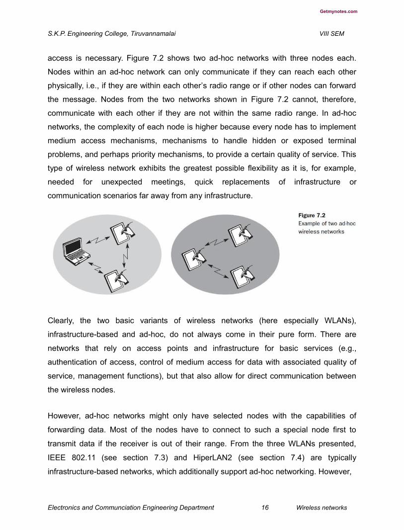
access is necessary. Figure 7.2 shows two ad-hoc networks with three nodes each.
Nodes within an ad-hoc network can only communicate if they can reach each other
physically, i.e., if they are within each other’s radio range or if other nodes can forward
the message. Nodes from the two networks shown in Figure 7.2 cannot, therefore,
communicate with each other if they are not within the same radio range. In ad-hoc
networks, the complexity of each node is higher because every node has to implement
medium access mechanisms, mechanisms to handle hidden or exposed terminal
problems, and perhaps priority mechanisms, to provide a certain quality of service. This
type of wireless network exhibits the greatest possible flexibility as it is, for example,
needed for unexpected meetings, quick replacements of infrastructure or
communication scenarios far away from any infrastructure.
Clearly, the two basic variants of wireless networks (here especially WLANs),
infrastructure-based and ad-hoc, do not always come in their pure form. There are
networks that rely on access points and infrastructure for basic services (e.g.,
authentication of access, control of medium access for data with associated quality of
service, management functions), but that also allow for direct communication between
the wireless nodes.
However, ad-hoc networks might only have selected nodes with the capabilities of
forwarding data. Most of the nodes have to connect to such a special node first to
transmit data if the receiver is out of their range. From the three WLANs presented,
IEEE 802.11 (see section 7.3) and HiperLAN2 (see section 7.4) are typically
infrastructure-based networks, which additionally support ad-hoc networking. However,
Electronics and Communciation Engineering Department 16 Wireless networks
Getmynotes.com
S.K.P. Engineering College, Tiruvannamalai VIII SEM
many implementations only offer the basic infrastructure-based version. The third
WLAN, Bluetooth (see section 7.5), is a typical wireless ad-hoc network. Bluetooth
focuses precisely on spontaneous ad-hoc meetings or on the simple connection of two
or more devices without requiring the setup of an infrastructure.
4. Explain in detail about IEEE 802.11 (L-3,CO-1)
The IEEE standard 802.11 (IEEE, 1999) specifies the most famous family of WLANs in
which many products are available. As the standard’s number indicates, this standard
belongs to the group of 802.x LAN standards, e.g., 802.3 Ethernet or 802.5 Token Ring.
This means that the standard specifies the physical and medium access layer adapted
to the special requirements of wireless LANs, but offers the same interface as the
others to higher layers to maintain interoperability. The primary goal of the standard was
the specification of a simple and robust
WLAN which offers time-bounded and asynchronous services. The MAC layer should
be able to operate with multiple physical layers, each of which exhibits a different
medium sense and transmission characteristic. Candidates for physical layers were
infra red and spread spectrum radio transmission techniques.
Additional features of the WLAN should include the support of power management to
save battery power, the handling of hidden nodes, and the ability to operate worldwide.
The 2.4 GHz ISM band, which is available in most countries around the world, was
chosen for the original standard. Data rates envisaged for the standard were 1 Mbit/s
mandatory and 2 Mbit/s optional.
The following sections will introduce the system and protocol architecture of the initial
IEEE 802.11 and then discuss each layer, i.e., physical layer and medium access. After
that, the complex and very important management functions of the standard are
presented. Finally, this subsection presents the enhancements of the original standard
for higher data rates, 802.11a (up to 54 Mbit/s at 5 GHz) and 802.11b (today the most
successful with 11 Mbit/s) together with further developments for security support,
harmonization, or other modulation schemes.
7.3.1 System architecture Wireless networks can exhibit two different basic system
architectures as shown in section 7.2: infrastructure-based or ad-hoc. Figure 7.3 shows
Electronics and Communciation Engineering Department 17 Wireless networks
Getmynotes.com
S.K.P. Engineering College, Tiruvannamalai VIII SEM
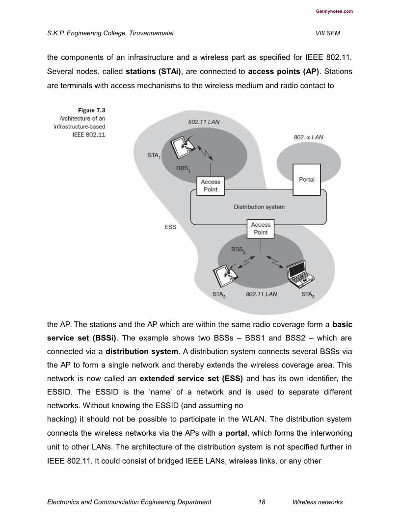
the components of an infrastructure and a wireless part as specified for IEEE 802.11.
Several nodes, called stations (STAi), are connected to access points (AP). Stations
are terminals with access mechanisms to the wireless medium and radio contact to
the AP. The stations and the AP which are within the same radio coverage form a basic
service set (BSSi). The example shows two BSSs – BSS1 and BSS2 – which are
connected via a distribution system. A distribution system connects several BSSs via
the AP to form a single network and thereby extends the wireless coverage area. This
network is now called an extended service set (ESS) and has its own identifier, the
ESSID. The ESSID is the ‘name’ of a network and is used to separate different
networks. Without knowing the ESSID (and assuming no
hacking) it should not be possible to participate in the WLAN. The distribution system
connects the wireless networks via the APs with a portal, which forms the interworking
unit to other LANs. The architecture of the distribution system is not specified further in
IEEE 802.11. It could consist of bridged IEEE LANs, wireless links, or any other
Electronics and Communciation Engineering Department 18 Wireless networks

Getmynotes.com
S.K.P. Engineering College, Tiruvannamalai VIII SEM
networks. However, distribution system services are defined in the standard
(although, many products today cannot interoperate and needs the additional standard
IEEE 802.11f to specify an inter access point protocol, see section 7.3.8). Stations can
select an AP and associate with it. The APs support roaming (i.e., changing access
points), the distribution system handles data transfer between the different APs. APs
provide synchronization within a BSS, support power management, and can control
medium access to support time-bounded service. These and further functions are
explained in the following sections. In addition to infrastructure-based networks, IEEE
802.11 allows the building of ad-hoc networks between stations, thus forming one or
more independent
BSSs (IBSS) as shown in Figure 7.4. In this case, an IBSS comprises a group of
stations using the same radio frequency. Stations STA1, STA2, and STA3 are in IBSS1,
STA4 and STA5 in IBSS2. This means for example that STA3 can communicate
directly with STA2 but not with STA5. Several IBSSs can either be formed via the
distance between the IBSSs (see Figure 7.4) or by using different carrier frequencies
(then the IBSSs could overlap physically). IEEE 802.11 does not specify any special
Electronics and Communciation Engineering Department 19 Wireless networks
Getmynotes.com
S.K.P. Engineering College, Tiruvannamalai VIII SEM
nodes that support routing, forwarding of data or exchange of topology information as,
e.g., HIPERLAN 1 (see section 7.4) or Bluetooth (see section 7.5).
Protocol architecture
As indicated by the standard number, IEEE 802.11 fits seamlessly into the other 802.x
standards for wired LANs (see Halsall, 1996; IEEE, 1990). Figure 7.5 shows the most
common scenario: an IEEE 802.11 wireless LAN connected to a switched IEEE 802.3
Ethernet via a bridge. Applications should not notice any difference apart from the lower
bandwidth and perhaps higher access time from the wireless LAN. The WLAN behaves
like a slow wired LAN. Consequently, the higher layers (application, TCP, IP) look the
same for wireless nodes as for wired nodes. The upper part of the data link control
layer, the logical link control (LLC), covers the differences of the medium access control
layers needed for the different media. In many of today’s networks, no explicit LLC layer
is visible. Further details like Ethertype or sub-network access protocol (SNAP) and
bridging technology are explained in, e.g., Perlman (1992). The IEEE 802.11 standard
only covers the physical layer PHY and medium access layer MAC like the other 802.x
LANs do. The physical layer is subdivided into the physical layer convergence
protocol (PLCP) and the physical medium dependent sublayer PMD (see Figure
7.6). The basic tasks of the MAC layer comprise medium access, fragmentation of user
data, and encryption. The
Electronics and Communciation Engineering Department 20 Wireless networks

Getmynotes.com
S.K.P. Engineering College, Tiruvannamalai VIII SEM
PLCP sublayer provides a carrier sense signal, called clear channel assessment (CCA),
and provides a common PHY service access point (SAP) independent of the
transmission technology. Finally, the PMD sublayer handles modulation and
encoding/decoding of signals. The PHY layer (comprising PMD and PLCP) and the
MAC layer will be explained in more detail in the following sections. Apart from the
protocol sublayers, the standard specifies management layers and the station
management. The MAC management supports the association and re-association of a
station to an access point and roaming between different access points. It also controls
authentication mechanisms, encryption, synchronization of a station with regard to an
Electronics and Communciation Engineering Department 21 Wireless networks

Getmynotes.com
S.K.P. Engineering College, Tiruvannamalai VIII SEM
access point, and power management to save battery power. MAC management also
maintains the MAC management information base (MIB). The main tasks of the PHY
management include channel tuning and PHY MIB maintenance. Finally, station
management interacts with both management layers and is responsible for additional
higher layer functions (e.g., control of bridging and interaction with the distribution
system in the case of an access point).
Physical layer
IEEE 802.11 supports three different physical layers: one layer based on infra red and
two layers based on radio transmission (primarily in the ISM band at 2.4 GHz, which is
available worldwide). All PHY variants include the provision of the clear channel
assessment signal (CCA). This is needed for the MAC mechanisms controlling medium
access and indicates if the medium is currently idle. The transmission technology (which
will be discussed later) determines exactly how this signal is obtained. The PHY layer
offers a service access point (SAP) with 1 or 2 Mbit/s transfer rate to the MAC layer
(basic version of the standard). The remainder of this section presents the three
versions of a PHY layer defined in the standard.
5. Explain the technique about Frequency hopping spread spectrum. (L-1,CO-1)
Frequency hopping spread spectrum (FHSS) is a spread spectrum technique which
allows for the coexistence of multiple networks in the same area by separating different
networks using different hopping sequences. The original standard defines 79 hopping
channels for North America and Europe, and 23 hopping channels for Japan (each with
a bandwidth of 1 MHz in the 2.4 GHz ISM band). The selection of a particular channel is
achieved by using a pseudo-random hopping pattern. National restrictions also
determine further parameters, e.g., maximum transmit power is 1 W in the US, 100 mW
EIRP (equivalent isotropic radiated power) in Europe and 10 mW/MHz in Japan. The
standard specifies Gaussian shaped FSK (frequency shift keying), GFSK, as
modulation for the FHSS PHY. For 1 Mbit/s a 2 level GFSK is used (i.e., 1 bit is mapped
to one frequency, a 4 level GFSK for 2 Mbit/s (i.e., 2 bits are mapped to one frequency).
Electronics and Communciation Engineering Department 22 Wireless networks
Getmynotes.com
S.K.P. Engineering College, Tiruvannamalai VIII SEM
While sending and receiving at 1 Mbit/s is mandatory for all devices, operation at 2
Mbit/s is optional. This facilitated the production of low-cost devices for the lower rate
only and more powerful devices for both transmission rates in the early days of 802.11.
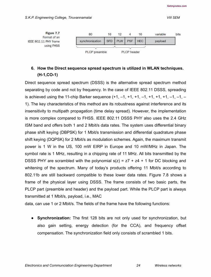
Figure 7.7 shows a frame of the physical layer used with FHSS. The frame
consists of two basic parts, the PLCP part (preamble and header) and the payload part.
While the PLCP part is always transmitted at 1 Mbit/s, payload, i.e. MAC data, can use
1 or 2 Mbit/s. Additionally, MAC data is scrambled using the polynomial s(z) = z7 + z4 +
1 for DC blocking and whitening of the spectrum.
The fields of the frame fulfill the following functions:
● Synchronization: The PLCP preamble starts with 80 bit synchronization, which
is a 010101... bit pattern. This pattern is used for synchronization of potential
receivers and signal detection by the CCA.
● Start frame delimiter (SFD): The following 16 bits indicate the start of the frame
and provide frame synchronization. The SFD pattern is 0000110010111101.
● PLCP_PDU length word (PLW): This first field of the PLCP header indicates the
length of the payload in bytes including the 32 bit CRC at the end of the payload.
PLW can range between 0 and 4,095.
● PLCP signalling field (PSF): This 4 bit field indicates the data rate of the
payload following. All bits set to zero (0000) indicates the lowest data rate of 1
Mbit/s. The granularity is 500 kbit/s, thus 2 Mbit/s is indicated by 0010 and the
maximum is 8.5 Mbit/s (1111). This system obviously does not accommodate
today’s higher data rates.
● Header error check (HEC): Finally, the PLCP header is protected by a 16 bit
checksum with the standard ITU-T generator polynomial G(x) = x16 + x12 + x5 +
1.
Electronics and Communciation Engineering Department 23 Wireless networks
Getmynotes.com
S.K.P. Engineering College, Tiruvannamalai VIII SEM
6. How the Direct sequence spread spectrum is utilized in WLAN techniques.
(H-1,CO-1)
Direct sequence spread spectrum (DSSS) is the alternative spread spectrum method
separating by code and not by frequency. In the case of IEEE 802.11 DSSS, spreading
is achieved using the 11-chip Barker sequence (+1, –1, +1, +1, –1, +1, +1, +1, –1, –1, –
1). The key characteristics of this method are its robustness against interference and its
insensitivity to multipath propagation (time delay spread). However, the implementation
is more complex compared to FHSS. IEEE 802.11 DSSS PHY also uses the 2.4 GHz
ISM band and offers both 1 and 2 Mbit/s data rates. The system uses differential binary
phase shift keying (DBPSK) for 1 Mbit/s transmission and differential quadrature phase
shift keying (DQPSK) for 2 Mbit/s as modulation schemes. Again, the maximum transmit
power is 1 W in the US, 100 mW EIRP in Europe and 10 mW/MHz in Japan. The
symbol rate is 1 MHz, resulting in a chipping rate of 11 MHz. All bits transmitted by the
DSSS PHY are scrambled with the polynomial s(z) = z7 + z4 + 1 for DC blocking and
whitening of the spectrum. Many of today’s products offering 11 Mbit/s according to
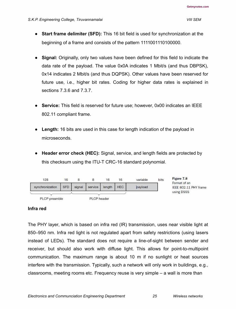
802.11b are still backward compatible to these lower data rates. Figure 7.8 shows a
frame of the physical layer using DSSS. The frame consists of two basic parts, the
PLCP part (preamble and header) and the payload part. While the PLCP part is always
transmitted at 1 Mbit/s, payload, i.e., MAC
data, can use 1 or 2 Mbit/s. The fields of the frame have the following functions:
● Synchronization: The first 128 bits are not only used for synchronization, but
also gain setting, energy detection (for the CCA), and frequency offset
compensation. The synchronization field only consists of scrambled 1 bits.
Electronics and Communciation Engineering Department 24 Wireless networks
Getmynotes.com
S.K.P. Engineering College, Tiruvannamalai VIII SEM
● Start frame delimiter (SFD): This 16 bit field is used for synchronization at the
beginning of a frame and consists of the pattern 1111001110100000.
● Signal: Originally, only two values have been defined for this field to indicate the
data rate of the payload. The value 0x0A indicates 1 Mbit/s (and thus DBPSK),
0x14 indicates 2 Mbit/s (and thus DQPSK). Other values have been reserved for
future use, i.e., higher bit rates. Coding for higher data rates is explained in
sections 7.3.6 and 7.3.7.
● Service: This field is reserved for future use; however, 0x00 indicates an IEEE
802.11 compliant frame.
● Length: 16 bits are used in this case for length indication of the payload in
microseconds.
● Header error check (HEC): Signal, service, and length fields are protected by
this checksum using the ITU-T CRC-16 standard polynomial.
Infra red
The PHY layer, which is based on infra red (IR) transmission, uses near visible light at
850–950 nm. Infra red light is not regulated apart from safety restrictions (using lasers
instead of LEDs). The standard does not require a line-of-sight between sender and
receiver, but should also work with diffuse light. This allows for point-to-multipoint
communication. The maximum range is about 10 m if no sunlight or heat sources
interfere with the transmission. Typically, such a network will only work in buildings, e.g.,
classrooms, meeting rooms etc. Frequency reuse is very simple – a wall is more than
Electronics and Communciation Engineering Department 25 Wireless networks
Getmynotes.com
S.K.P. Engineering College, Tiruvannamalai VIII SEM
enough to shield one IR based IEEE 802.11 network from another. ( comparison
between IR and radio transmission and Wesel, 1998 for more details.) Today, no
products are available that offer infra red communication based on 802.11. Proprietary
products offer, e.g., up to 4 Mbit/s using diffuse infra red light. Alternatively, directed infra
red communication based on IrDA can be used (IrDA, 2002).
Medium access control layer The MAC layer has to fulfill several tasks. First of all, it has
to control medium access, but it can also offer support for roaming, authentication, and
power conservation. The basic services provided by the MAC layer are the mandatory
asynchronous data service and an optional time-bounded service. While 802.11
only offers the asynchronous service in ad-hoc network mode, both service types can
be offered using an infrastructure-based network together with the access point
coordinating medium access. The asynchronous service supports broadcast and multi-
cast packets, and packet exchange is based on a ‘best effort’ model, i.e., no delay
bounds can be given for transmission. The following three basic access mechanisms
have been defined for IEEE 802.11: the mandatory basic method based on a version of
CSMA/CA, an optional method avoiding the hidden terminal problem, and finally a
contention- free polling method for time-bounded service. The first two methods are also
summarized as distributed coordination function (DCF), the third method is called
point coordination function (PCF). DCF only offers asynchronous service, while PCF
offers both asynchronous and time-bounded service but needs an access point to
control medium access and to avoid contention. The MAC mechanisms are also called
distributed foundation wireless
medium access control (DFWMAC). For all access methods, several parameters for
controlling the waiting time before medium access are important. Figure 7.9 shows the
three different rameters that define the priorities of medium access. The values of the
parameters depend on the PHY and are defined in relation to a slot time. Slot time is
derived from the medium propagation delay, transmitter delay, and other PHY
dependent parameters. Slot time is 50 μs for FHSS and 20 μs for DSSS. The medium,
as shown, can be busy or idle (which is detected by the CCA). If the medium is busy
this can be due to data frames or other control frames. During a contention phase
several nodes try to access the medium.
Electronics and Communciation Engineering Department 26 Wireless networks

Getmynotes.com
S.K.P. Engineering College, Tiruvannamalai VIII SEM
● Short inter-frame spacing (SIFS): The shortest waiting time for medium access
(so the highest priority) is defined for short control messages, such as
acknowledgements of data packets or polling responses. For DSSS SIFS is 10
μs and for FHSS it is 28 μs. The use of this parameter will be explained in
sections 7.3.4.1 through 7.3.4.3.
● PCF inter-frame spacing (PIFS): A waiting time between DIFS and SIFS (and
thus a medium priority) is used for a time-bounded service. An access point
polling other nodes only has to wait PIFS for medium access (see section
7.3.4.3). PIFS is defined as SIFS plus one slot time.
● DCF inter-frame spacing (DIFS): This parameter denotes the longest waiting
time and has the lowest priority for medium access. This waiting time is used for
asynchronous data service within a contention period (this parameter and the
basic access method are explained in section 7.3.4.1). DIFS is defined as SIFS
plus two slot times. 7.3.4.1 Basic DFWMAC-DCF using CSMA/CA The
mandatory access mechanism of IEEE 802.11 is based on carrier sense
multiple access with collision avoidance (CSMA/CA), which is a random
access scheme with carrier sense and collision avoidance through random
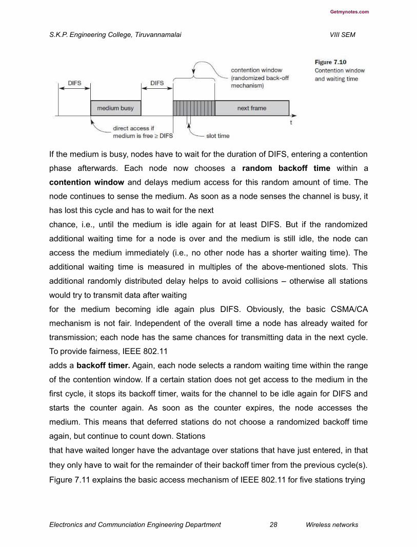
backoff. The basic CSMA/CA mechanism is shown in Figure 7.10. If the medium
is idle for at least the duration of DIFS (with the help of the CCA signal of the
physical layer), a node can access the medium at once. This allows for short
access delay under light load. But as more and more nodes try to access the
medium, additional mechanisms are needed.

Electronics and Communciation Engineering Department 27 Wireless networks
Getmynotes.com
S.K.P. Engineering College, Tiruvannamalai VIII SEM
If the medium is busy, nodes have to wait for the duration of DIFS, entering a contention
phase afterwards. Each node now chooses a random backoff time within a
contention window and delays medium access for this random amount of time. The
node continues to sense the medium. As soon as a node senses the channel is busy, it
has lost this cycle and has to wait for the next
chance, i.e., until the medium is idle again for at least DIFS. But if the randomized
additional waiting time for a node is over and the medium is still idle, the node can
access the medium immediately (i.e., no other node has a shorter waiting time). The
additional waiting time is measured in multiples of the above-mentioned slots. This
additional randomly distributed delay helps to avoid collisions – otherwise all stations
would try to transmit data after waiting
for the medium becoming idle again plus DIFS. Obviously, the basic CSMA/CA
mechanism is not fair. Independent of the overall time a node has already waited for
transmission; each node has the same chances for transmitting data in the next cycle.
To provide fairness, IEEE 802.11
adds a backoff timer. Again, each node selects a random waiting time within the range
of the contention window. If a certain station does not get access to the medium in the
first cycle, it stops its backoff timer, waits for the channel to be idle again for DIFS and
starts the counter again. As soon as the counter expires, the node accesses the
medium. This means that deferred stations do not choose a randomized backoff time
again, but continue to count down. Stations
that have waited longer have the advantage over stations that have just entered, in that
they only have to wait for the remainder of their backoff timer from the previous cycle(s).
Figure 7.11 explains the basic access mechanism of IEEE 802.11 for five stations trying
Electronics and Communciation Engineering Department 28 Wireless networks

Getmynotes.com
S.K.P. Engineering College, Tiruvannamalai VIII SEM
to send a packet at the marked points in time. Station3 has the first request from a
higher layer to send a packet packet arrival at the MAC SAP). The station senses the
medium, waits for DIFS and accesses the medium, i.e., sends the packet. Station1,
station2, and station5 have to wait at least until the medium is idle for DIFS again after
station3 has stopped sending. Now all three stations choose a backoff time within the
contention window and start counting down their backoff timers.
Figure 7.11 shows the random backoff time of station1 as sum of boe (the elapsed
backoff time) and bor (the residual backoff time). The same is shown for station5.
Station2 has a total backoff time of only boe and gets access to the medium first. No
residual backoff time for station2 is shown. The backoff timers of station1 and station5
stop, and the stations store their residual backoff times. While a new station has to
choose its backoff time from the whole contention window, the two old stations have
statistically smaller backoff values. The older values are on average lower than the new
ones. Now station4 wants to send a packet as well, so after DIFS waiting time, three
stations try to get access. It can now happen, as shown in the figure, that two stations
accidentally have the same backoff time, no matter whether remaining or newly chosen.
This results in a collision on the medium as shown, i.e., the trans-
mitted frames are destroyed. Station1 stores its residual backoff time again. In the last
cycle shown station1 finally gets access to the medium, while station4 and station5
have to wait. A collision triggers a retransmission with a new random selection of the
backoff time. Retransmissions are not privileged. Still, the access scheme has problems
under heavy or light load. Depending on the size of the contention window (CW), the
random values can either be
Electronics and Communciation Engineering Department 29 Wireless networks

Getmynotes.com
S.K.P. Engineering College, Tiruvannamalai VIII SEM
too close together (causing too many collisions) or the values are too high (causing
unnecessary delay). The system tries to adapt to the current number of stations trying to
send. The contention window starts with a size of, e.g., CWmin = 7. Each time a
collision occurs, indicating a higher load on the medium, the contention window doubles
up to a maximum of, e.g., CWmax = 255 (the window can take on the values 7, 15, 31,
63, 127, and 255). The larger the contention window is, the greater is the resolution
power of the randomized scheme. It is less likely to choose the same random backoff
time using a large CW. However, under a light load, a small CW ensures shorter access
delays. This algorithm is also called exponential backoff and is already familiar from
IEEE 802.3 CSMA/CD in a similar version. While this process describes the complete
access mechanism for broadcast frames, an additional feature is provided by the
standard for unicast data transfer. Figure 7.12 shows a sender accessing the medium
and sending its data. But now, the receiver answers directly with an acknowledgement
(ACK). The receiver accesses the medium after waiting for a duration of SIFS so no
other station can access the medium in the meantime and cause a collision. The other
stations have to wait for DIFS plus their backoff time. This acknowledgement ensures
the correct reception (correct checksum CRC at the receiver) of a frame on the MAC
layer, which is especially important in error-prone environments
such as wireless connections. If no ACK is returned, the sender automatically
retransmits the frame. But now the sender has to wait again and compete for the access
right. There are no special rules for retransmissions. The number of retransmissions is
limited, and final failure is reported to the higher layer. 7.3.4.2 DFWMAC-DCF with
RTS/CTS extension Section 3.1 discussed the problem of hidden terminals, a situation
that can also occur in IEEE 802.11 networks. This problem occurs if one station can
receive two others, but those stations cannot receive each other. The two stations may
Electronics and Communciation Engineering Department 30 Wireless networks

Getmynotes.com
S.K.P. Engineering College, Tiruvannamalai VIII SEM
sense the channel is idle, send a frame, and cause a collision at the receiver in the
middle. To deal with this problem, the standard defines an additional mechanism using
two control packets, RTS and CTS. The use of the mechanism is optional; however,
every 802.11 node has to implement the functions to react properly upon reception of
RTS/CTS control packets. Figure 7.13 illustrates the use of RTS and CTS. After waiting
for DIFS (plus a random backoff time if the medium was busy), the sender can issue a
request to send (RTS) control packet. The RTS packet thus is not given any higher
priority compared to other data packets. The RTS packet includes the receiver of the
data transmission to come and the duration of the whole data transmission. This
duration specifies the time interval necessary to transmit the whole data frame and the
acknowledgement related to it. Every node receiving this RTS now has to set its net
allocation vector (NAV) in accordance with the duration field. The NAV then specifies
the earliest point at which the station can try to access the medium again. If the receiver
of the data transmission receives the RTS, it answers with a clear to send (CTS)
message after waiting for SIFS. This CTS packet contains the duration field again and
all stations receiving this packet from the receiver of the intended data transmission
have to adjust their NAV. The latter set of receivers need not be the same as the first set
receiving the RTS packet. Now all nodes within receiving distance around sender and
receiver are informed that they have to wait more time before accessing the medium.
Basically, this mechanism reserves the medium for one sender exclusively (this is why it
is sometimes called a virtual reservation scheme).
Electronics and Communciation Engineering Department 31 Wireless networks

Getmynotes.com
S.K.P. Engineering College, Tiruvannamalai VIII SEM
Finally, the sender can send the data after SIFS. The receiver waits for SIFS after
receiving the data packet and then acknowledges whether the transfer was correct. The
transmission has now been completed, the NAV in each node marks the medium as
free and the standard cycle can start again. Within this scenario (i.e., using RTS and
CTS to avoid the hidden terminal problem), collisions can only occur at the beginning
while the RTS is sent. Two or more stations may start sending at the same time (RTS or
other data packets). Using RTS/CTS can result in a non-negligible overhead causing a
waste of bandwidth and higher delay. An RTS threshold can determine when to use the
additional mechanism (basically at larger frame sizes) and when to disable it (short
frames). Chhaya (1996) and Chhaya (1997) give an overview of the synchronous
services in 802.11 and discuss performance under different load scenarios. Wireless
LANs have bit error rates in transmission that are typically several orders of magnitude
higher than, e.g., fiber optics. The probability of an erroneous frame is much higher for
wireless links assuming the same frame length. One way to decrease the error
probability of frames is to use shorter frames. In this case, the bit error rate is the same,
but now only short frames are destroyed and, the frame error rate decreases. However,
the mechanism of fragmenting a user data packet into several smaller parts should be
transparent for a user. The MAC layer should have the possibility of adjusting the
transmission frame size to the current error rate on the medium. The IEEE 802.11
standard specifies a fragmentation mode (see Figure 7.14). Again, a sender can send
an RTS control packet to reserve the medium after a waiting time of DIFS. This RTS
packet now includes the duration for the transmission of the first fragment and the
corresponding acknowledgement. A certain set of nodes may receive this RTS and set
their NAV according to the duration field. The receiver answers with a CTS, again
including the duration of the transmission up to the acknowledgement. A (possibly
different) set of receivers gets this CTS message and sets the NAV.
Electronics and Communciation Engineering Department 32 Wireless networks

Getmynotes.com
S.K.P. Engineering College, Tiruvannamalai VIII SEM
As shown in Figure 7.13, the sender can now send the first data frame, frag1, after
waiting only for SIFS. The new aspect of this fragmentation mode is that it includes
another duration value in the frame frag1. This duration field reserves the medium for
the duration of the transmission following, comprising the second fragment and its
acknowledgement. Again, several nodes may receive this reservation and adjust their
NAV. If all nodes are static and transmission conditions have not changed, then the set
of nodes receiving the duration field in frag1 should be the same as the set that has
received the initial reservation in the RTS control packet. However, due to the mobility of
nodes and changes in the environment, this could also be a different set of nodes.
The receiver of frag1 answers directly after SIFS with the acknowledgement packet
ACK1 including the reservation for the next transmission as shown. Again, a fourth set
of nodes may receive this reservation and adjust their NAV (which again could be the
same as the second set of nodes that has received the reservation in the CTS frame). If
frag2 was not the last frame of this transmission, it would also include a new duration for
the third consecutive transmission. (In the example shown, frag2 is the last fragment of
this transmission so the sender does not reserve the medium any longer.) The receiver
acknowledges this second fragment, not reserving the medium again. After ACK2, all
nodes can compete for the medium again after having waited for DIFS.
7. Explain the mechanisms for minimum transmission bandwidth . (H-1,CO-1)
The two access mechanisms presented so far cannot guarantee a maximum access
delay or minimum transmission bandwidth. To provide a time-bounded service, the
Electronics and Communciation Engineering Department 33 Wireless networks

Getmynotes.com
S.K.P. Engineering College, Tiruvannamalai VIII SEM
standard specifies a point coordination function (PCF) on top of the standard DCF
mechanisms. Using PCF requires an access point that controls medium access and
polls the single nodes. Ad-hoc networks cannot use this function so, provide no QoS but
‘best effort’ in IEEE 802.11 WLANs.
The point co-ordinator in the access point splits the access time into super frame
periods as shown in Figure 7.15. A super frame comprises a contentionfree period
and a contention period. The contention period can be used for the two access
mechanisms presented above. The figure also shows several wireless stations (all on
the same line) and the stations’ NAV (again on one line).
At time t0 the contention-free period of the super frame should theoretically start, but
another station is still transmitting data (i.e., the medium is busy). This means that PCF
also defers to DCF, and the start of the super frame may be postponed. The only
possibility of avoiding variations is not to have any contention period at all. After the
medium has been idle until t1, the point coordinator has to wait for PIFS before
accessing the medium. As PIFS is smaller than DIFS, no other station can start sending
earlier. The point coordinator now sends data D1 downstream to the first wireless
station. This station can answer at once after SIFS (see Figure 7.15). After waiting for
Electronics and Communciation Engineering Department 34 Wireless networks

Getmynotes.com
S.K.P. Engineering College, Tiruvannamalai VIII SEM
SIFS again, the point coordinator can poll the second station by sending D2. This
station may answer upstream to the coordinator with data U2. Polling continues with the
third node. This time the node has nothing to answer and the point coordinator will not
receive a packet after SIFS. After waiting for PIFS, the coordinator can resume polling
the stations. Finally, the point coordinator can issue an end marker (CFend), indicating
that the contention period may start again. Using PCF automatically sets the NAV,
preventing other stations from sending. In the example, the contention-free period
planned initially would have been from t0 to t3. However, the point coordinator finished
polling earlier, shifting the end of the contention-free period to t2. At t4, the cycle starts
again with the next super frame.
The transmission properties of the whole wireless network are now determined by the
polling behavior of the access point. If only PCF is used and polling is distributed evenly,
the bandwidth is also distributed evenly among all polled nodes. This would resemble a
static, centrally controlled time division multiple access (TDMA) system with time
division duplex (TDD) transmission. This method comes with an overhead if nodes have
nothing to send, but the access point polls them permanently. Anastasi (1998)
elaborates the example of voice transmission using 48 byte packets as payload. In this
case, PCF introduces an overhead of 75 byte. 7.3.4.4 MAC frames Figure 7.16 shows
the basic structure of an IEEE 802.11 MAC data frame together with the content of the
frame control field. The fields in the figure refer to the following:
● Frame control: The first 2 bytes serve several purposes. They contain several
sub-fields as explained after the MAC frame.
● Duration/ID: If the field value is less than 32,768, the duration field contains the
value indicating the period of time in which the medium is occupied (in μs). This
field is used for setting the NAV for the virtual reservation mechanism using
RTS/CTS and during fragmentation. Certain values above 32,768 are reserved
for identifiers.
● Address 1 to 4: The four address fields contain standard IEEE 802 MAC
addresses (48 bit each), as they are known from other 802.x LANs. The meaning
of each address

Electronics and Communciation Engineering Department 35 Wireless networks

Getmynotes.com
S.K.P. Engineering College, Tiruvannamalai VIII SEM
depends on the DS bits in the frame control field and is explained in more detail in a
separate paragraph.
● Sequence control: Due to the acknowledgement mechanism frames may be
duplicated. Therefore a sequence number is used to filter duplicates.
● Data: The MAC frame may contain arbitrary data (max. 2,312 byte), which is
transferred transparently from a sender to the receiver(s).
● Checksum (CRC): Finally, a 32 bit checksum is used to protect the frame as it is
common practice in all 802.x networks. The frame control field shown in Figure
7.16 contains the following fields:
● Protocol version: This 2 bit field indicates the current protocol version and is fixed to
0 by now. If major revisions to the standard make it incompatible with the current
version, this value will be increased.
● Type: The type field determines the function of a frame: management (=00),
control (=01), or data (=10). The value 11 is reserved. Each type has several
subtypes as indicated in the following field.
● Subtype: Example subtypes for management frames are: 0000 for association
request, 1000 for beacon. RTS is a control frame with subtype 1011, CTS is
coded as 1100. User data is transmitted as data frame with subtype 0000. All
details can be found in IEEE, 1999.
● To DS/From DS: Explained in the following in more detail.
Electronics and Communciation Engineering Department 36 Wireless networks
Getmynotes.com
S.K.P. Engineering College, Tiruvannamalai VIII SEM
● More fragments: This field is set to 1 in all data or management frames that
have another fragment of the current MSDU to follow.
● Retry: If the current frame is a retransmission of an earlier frame, this bit is set to
1. With the help of this bit it may be simpler for receivers to eliminate duplicate
frames.
● Power management: This field indicates the mode of a station after successful
transmission of a frame. Set to 1 the field indicates that the station goes into
power-save mode. If the field is set to 0, the station stays active.
● More data: In general, this field is used to indicate a receiver that a sender has
more data to send than the current frame. This can be used by an access point
to indicate to a station in power-save mode that more packets are buffered. Or it
can be used by a station to indicate to an access point after being polled that
more polling is necessary as the station has more data ready to transmit.
● Wired equivalent privacy (WEP): This field indicates that the standard security
mechanism of 802.11 is applied. However, due to many weaknesses found in the
WEP algorithm higher layer security should be used to secure an 802.11 network
(Borisov, 2001).
● Order: If this bit is set to 1 the received frames must be processed in strict order.
MAC frames can be transmitted between mobile stations; between mobile
stations and an access point and between access points over a DS (see Figure
7.3). Two bits within the Frame Control field, ‘to DS’ and ‘from DS’, differentiate
these cases and control the meaning of the four addresses used. Table 7.1 gives
an overview of the four possible bit values of the DS bits and the associated
interpretation of the four address fields.

Electronics and Communciation Engineering Department 37 Wireless networks

Getmynotes.com
S.K.P. Engineering College, Tiruvannamalai VIII SEM
Every station, access point or wireless node, filters on address 1. This address
identifies the physical receiver(s) of the frame. Based on this address, a station can
decide whether the frame is relevant or not. The second address, address 2,
represents the physical transmitter of a frame. This information is important because
this particular sender is also the recipient of the MAC layer acknowledgement. If a
packet from a transmitter (address 2) is received by the receiver with address 1, this
receiver in turn acknowledges the data packet using address 2 as receiver address as
shown in the ACK packet in Figure 7.17. The remaining two addresses, address 3 and
address 4, are mainly necessary for the logical assignment of frames (logical sender,
BSS identifier, logical receiver). If address 4 is not needed the field is omitted. For
addressing, the following four scenarios are possible:
● Ad-hoc network: If both DS bits are zero, the MAC frame constitutes a packet
which is exchanged between two wireless nodes without a distribution system.
DA indicates the destination address, SA the source address of the frame,
which are identical to the physical receiver and sender addresses respectively.
The third address identifies the basic service set (BSSID) (see Figure 7.4), the
fourth address is unused.
● Infrastructure network, from AP: If only the ‘from DS’ bit is set, the frame
physically originates from an access point. DA is the logical and physical
receiver, the second address identifies the BSS, the third address specifies the
logical sender, the source address of the MAC frame. This case is an example
for a packet sent to the receiver via the access point.
Electronics and Communciation Engineering Department 38 Wireless networks


Getmynotes.com
S.K.P. Engineering College, Tiruvannamalai VIII SEM
● Infrastructure network, to AP: If a station sends a packet to another station via
the access point, only the ‘to DS’ bit is set. Now the first address represents the
physical receiver of the frame, the access point, via the BSS identifier. The
second address is the logical and physical sender of the frame, while the third
address indicates the logical receiver.
● Infrastructure network, within DS: For packets transmitted between two
access points over the distribution system, both bits are set. The first receiver
address (RA), represents the MAC address of the receiving access point.
Similarly, the second address transmitter address (TA), identifies the sending
access point within the distribution system. Now two more addresses are needed
to identify the original destination DA of the frame and the original source of the
frame SA. Without these additional addresses, some encapsulation mechanism
would be necessary to transmit MAC frames over the distribution system
transparently. Figure 7.17 shows three control packets as examples for many
special packets defined in the standard. The acknowledgement packet (ACK)
is used to acknowledge the correct reception of a data frame as shown in Figure
7.12. The receiver address is directly copied from the address 2 field of the
immediately previous frame. If no more fragments follow for a certain frame the
duration field is set to 0. Otherwise the duration value of the previous frame
(minus the time required to transmit the ACK minus SIFS) is stored in the
duration field.
8. Brief about MAC management techniques used in IEEE 802.11. (H-3,CO-1)
MAC management plays a central role in an IEEE 802.11 station as it more or less
controls all functions related to system integration, i.e., integration of a wireless station
into a BSS, formation of an ESS, synchronization of stations etc.
The following functional groups have been identified and will be discussed in more
detail in the following sections:
Electronics and Communciation Engineering Department 39 Wireless networks

Getmynotes.com
S.K.P. Engineering College, Tiruvannamalai VIII SEM
● Synchronization: Functions to support finding a wireless LAN, synchronization
of internal clocks, generation of beacon signals.
● Power management: Functions to control transmitter activity for power
conservation, e.g., periodic sleep, buffering, without missing a frame.
● Roaming: Functions for joining a network (association), changing access points,
scanning for access points.
● Management information base (MIB): All parameters representing the current
state of a wireless station and an access point are stored within a MIB for internal
and external access. A MIB can be accessed via standardized protocols such as
the simple network management protocol (SNMP).
Synchronization
Each node of an 802.11 network maintains an internal clock. To synchronize the clocks
of all nodes, IEEE 802.11 specifies a timing synchronization function (TSF). As we
will see in the following section, synchronized clocks are needed for power
management, but also for coordination of the PCF and for synchronization of the
hopping sequence in an FHSS system. Using PCF, the local timer of a node can predict
the start of a super frame, i.e., the contention free and contention period. FHSS physical
layers need the same hopping sequences so that all nodes can communicate within a
BSS.
Within a BSS, timing is conveyed by the (quasi)periodic transmissions of a beacon
frame. A beacon contains a timestamp and other management information used for
power management and roaming (e.g., identification of the BSS). The timestamp is
used by a node to adjust its local clock. The node is not required to hear every beacon
to stay synchronized; however, from time to time internal clocks should be adjusted. The
transmission of a beacon frame is not always periodic because the beacon frame is also
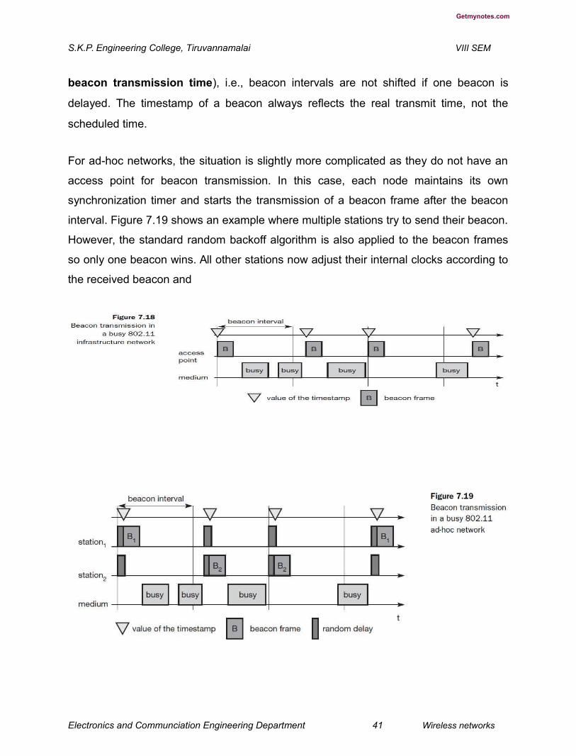
deferred if the medium is busy. Within infrastructure-based networks, the access point
performs synchronization by transmitting the (quasi)periodic beacon signal, whereas all
other wireless nodes adjust their local timer to the time stamp. This represents the
simple case shown in Figure 7.18. The access point is not always able to send its
beacon B periodically if the medium is busy. However, the access point always tries to
schedule transmissions according to the expected beacon interval (target
Electronics and Communciation Engineering Department 40 Wireless networks
Getmynotes.com
S.K.P. Engineering College, Tiruvannamalai VIII SEM
beacon transmission time), i.e., beacon intervals are not shifted if one beacon is
delayed. The timestamp of a beacon always reflects the real transmit time, not the
scheduled time.
For ad-hoc networks, the situation is slightly more complicated as they do not have an
access point for beacon transmission. In this case, each node maintains its own
synchronization timer and starts the transmission of a beacon frame after the beacon
interval. Figure 7.19 shows an example where multiple stations try to send their beacon.
However, the standard random backoff algorithm is also applied to the beacon frames
so only one beacon wins. All other stations now adjust their internal clocks according to
the received beacon and
Electronics and Communciation Engineering Department 41 Wireless networks

Getmynotes.com
S.K.P. Engineering College, Tiruvannamalai VIII SEM
suppress their beacons for this cycle. If collision occurs, the beacon is lost. In this
scenario, the beacon intervals can be shifted slightly because all clocks may vary as
may the start of a beacon interval from a node’s point of view. However, after successful
synchronization all nodes again have the same consistent view.
Power management
Wireless devices are battery powered (unless a solar panel is used). Therefore, power-
saving mechanisms are crucial for the commercial success of such devices. Standard
LAN protocols assume that stations are always ready to receive data, although
receivers are idle most of the time in lightly loaded networks. However, this permanent
readiness of the receiving module is critical for battery life as the receiver current may
be up to 100 mA (Woesner, 1998). The basic idea of IEEE 802.11 power management
is to switch off the transceiver whenever it is not needed. For the sending device this is
simple to achieve as the transfer is triggered by the device itself. However, since the
power management of a receiver cannot know in advance when the transceiver has to
be active for a specific packet, it has to ‘wake up’ the transceiver periodically.
Switching off the transceiver should be transparent to existing protocols and should be
flexible enough to support different applications. However, throughput can be traded-off
for battery life. Longer off-periods save battery life but reduce average throughput and
vice versa. The basic idea of power saving includes two states for a station: sleep and
awake, and buffering of data in senders. If a sender intends to communicate with a
power-saving station it has to buffer data if the station is asleep. The sleeping station on
the other hand has to wake up periodically and stay awake for a certain time. During
this time, all senders can announce the destinations of their buffered data frames. If a
station detects that it is a destination of a buffered packet it has to stay awake until the
transmission takes place. Waking up at the right moment requires the timing
synchronization function (TSF) introduced in section 7.3.5.1. All stations have to
wake up or be awake at the same time.
Power management in infrastructure-based networks is much simpler
compared to ad-hoc networks. The access point buffers all frames destined for stations
Electronics and Communciation Engineering Department 42 Wireless networks

Getmynotes.com
S.K.P. Engineering College, Tiruvannamalai VIII SEM
operating in power-save mode. With every beacon sent by the access point, a traffic
indication map (TIM) is transmitted. The TIM contains a list of stations for which
unicast data frames are buffered in the access point. The TSF assures that the sleeping
stations will wake up periodically and listen to the beacon and TIM. If the TIM indicates
a unicast frame buffered for the station, the station stays awake for transmission. For
multi-cast/broadcast transmission, stations will always stay awake. Another reason for
waking up is a frame which has to be transmitted from the station to the access point. A
sleeping station still has the TSF timer running. Figure 7.20 shows an example with an
access point and one station. The state of the medium is indicated. Again, the access
point transmits a beacon frame each beacon interval. This interval is now the same as
the TIM interval. Additionally, the access point maintains a delivery traffic indication
map (DTIM) interval for sending broadcast/multicast frames. The DTIM interval is
always a multiple of the TIM interval. All stations (in the example, only one is shown)
wake up prior to an expected TIM or DTIM. In the first case, the access point has to
transmit a broadcast frame and the station stays awake to receive it. After receiving the
broadcast frame, the station returns to sleeping mode. The station wakes up again just
before the next TIM transmission. This time the TIM is delayed due to a busy medium
so, the station stays awake. The access point has nothing to send and the station goes
back to sleep. At the next TIM interval, the access point indicates that the station is the
destination for a buffered frame. The station answers with a PS (power saving) poll and
stays awake to receive data. The access point then transmits the data for the station,
the station acknowledges the receipt and may also send some
Electronics and Communciation Engineering Department 43 Wireless networks
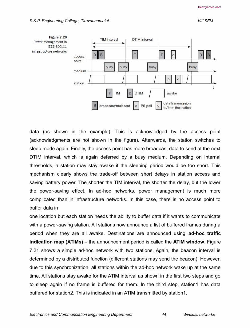
Getmynotes.com
S.K.P. Engineering College, Tiruvannamalai VIII SEM
data (as shown in the example). This is acknowledged by the access point
(acknowledgments are not shown in the figure). Afterwards, the station switches to
sleep mode again. Finally, the access point has more broadcast data to send at the next
DTIM interval, which is again deferred by a busy medium. Depending on internal
thresholds, a station may stay awake if the sleeping period would be too short. This
mechanism clearly shows the trade-off between short delays in station access and
saving battery power. The shorter the TIM interval, the shorter the delay, but the lower
the power-saving effect. In ad-hoc networks, power management is much more
complicated than in infrastructure networks. In this case, there is no access point to
buffer data in
one location but each station needs the ability to buffer data if it wants to communicate
with a power-saving station. All stations now announce a list of buffered frames during a
period when they are all awake. Destinations are announced using ad-hoc traffic
indication map (ATIMs) – the announcement period is called the ATIM window. Figure
7.21 shows a simple ad-hoc network with two stations. Again, the beacon interval is
determined by a distributed function (different stations may send the beacon). However,
due to this synchronization, all stations within the ad-hoc network wake up at the same
time. All stations stay awake for the ATIM interval as shown in the first two steps and go
to sleep again if no frame is buffered for them. In the third step, station1 has data
buffered for station2. This is indicated in an ATIM transmitted by station1.
Electronics and Communciation Engineering Department 44 Wireless networks

Getmynotes.com
S.K.P. Engineering College, Tiruvannamalai VIII SEM
Station2 acknowledges this ATIM and stays awake for the transmission. After the ATIM
window, station1 can transmit the data frame, and station2 acknowledges its receipt. In
this case, the stations stay awake for the next beacon.
One problem with this approach is that of scale. If many stations within an ad-hoc
network operate in power-save mode, they may also want to transmit their ATIM within
the ATIM window. More ATIM transmissions take place, more collisions happen and
more stations are deferred. The access delay of large networks is difficult to predict.
QoS guarantees can not be given under heavy load.
8. Explain the clear concept about roaming. (H-1,CO-1)
Typically, wireless networks within buildings require more than just one access point to
cover all rooms. Depending on the solidity and material of the walls, one access point
has a transmission range of 10–20 m if transmission is to be of decent quality. Each
storey of a building needs its own access point(s) as quite often walls are thinner than
floors. If a user walks around with a wireless station, the station has to move from one
access point to another to provide uninterrupted service. Moving between access points
is called roaming. The term “handover” or “handoff” as used in the context of mobile or
cellular phone systems would be more appropriate as it is simply a change of the active
cell. However, for WLANs roaming is more common.
Electronics and Communciation Engineering Department 45 Wireless networks
Getmynotes.com
S.K.P. Engineering College, Tiruvannamalai VIII SEM
The steps for roaming between access points are:
● A station decides that the current link quality to its access point AP1
is too poor. The station then starts scanning for another access
point.
● Scanning involves the active search for another BSS and can also be used for
setting up a new BSS in case of ad-hoc networks. IEEE 802.11 specifies
scanning on single or multiple channels (if available at the physical layer) and
differentiates between passive scanning and active scanning. Passive scanning
simply means listening into the medium to find other networks, i.e.,
receiving the beacon of another network issued by the synchronization function within
an access point. Active scanning comprises sending a probe on each channel and
waiting for a response. Beacon and probe responses contain the information necessary
to join the new BSS.
● The station then selects the best access point for roaming based on, e.g., signal
strength, and sends an association request to the selected access point AP2.
● The new access point AP2 answers with an association response. If the
response is successful, the station has roamed to the new access point AP2.
Otherwise, the station has to continue scanning for new access points.
● The access point accepting an association request indicates the new station in its
BSS to the distribution system (DS). The DS then updates its database, which
contains the current location of the wireless stations. This database is needed for
forwarding frames between different BSSs, i.e. between the different access
points controlling the BSSs, which combine to form an ESS (see Figure 7.3).
Additionally, the DS can inform the old access point AP1 that the station is no
longer within its BSS.
Unfortunately, many products implemented proprietary or incompatible versions of
protocols that support roaming and inform the old access point about the change in the

Electronics and Communciation Engineering Department 46 Wireless networks

Getmynotes.com
S.K.P. Engineering College, Tiruvannamalai VIII SEM
station’s location. The standard IEEE 802.11f (Inter Access Point Protocol, IAPP)
should provide a compatible solution for all vendors. This also includes load-balancing
between access points and key generation for security algorithms based on IEEE
802.1x (IEEE, 2001).
9. Explain in detail about 802.11b standard. (L-1,CO-1)
As standardization took some time, the capabilities of the physical layers also evolved.
Soon after the first commercial 802.11 products came on the market some companies
offered proprietary solutions with 11 Mbit/s. To avoid market segmentation, a common
standard, IEEE 802.11b (IEEE 1999) soon followed and was added as supplement to
the original standard (Higher-speed physical layer extension in the 2.4 GHz band). This
standard describes a new PHY layer and is by far the most successful version of IEEE
802.11 available today. Do not get confused about the fact that 802.11b hit the market
before 802.11a. The standards are named according to the order in which the
respective study groups have been established. As the name of the supplement implies,
this standard only defines a new PHY layer. All the MAC schemes, management
procedures etc. explained above are still used. Depending on the current interference
and the distance between sender and receiver 802.11b systems offer 11, 5.5, 2, or 1
Mbit/s. Maximum user data rate is approx 6 Mbit/s. The lower data rates 1 and 2 Mbit/s
use the 11-chip Barker sequence as explained in section 7.3.3.2 and DBPSK or
DQPSK, respectively.
The new data rates, 5.5 and 11 Mbit/s, use 8-chip complementary code keying (CCK)
(see IEEE, 1999, or Pahlavan, 2002, for details). The standard defines several packet
formats for the physical layer. The mandatory format interoperates with the original
versions of 802.11. The
optional versions provide a more efficient data transfer due to shorter headers/different
coding schemes and can coexist with other 802.11 versions. However, the standard
states that control all frames shall be transmitted at one of the basic rates, so they will
Electronics and Communciation Engineering Department 47 Wireless networks
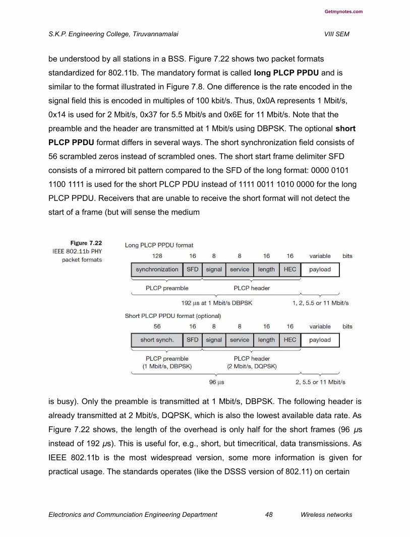
Getmynotes.com
S.K.P. Engineering College, Tiruvannamalai VIII SEM
be understood by all stations in a BSS. Figure 7.22 shows two packet formats
standardized for 802.11b. The mandatory format is called long PLCP PPDU and is
similar to the format illustrated in Figure 7.8. One difference is the rate encoded in the
signal field this is encoded in multiples of 100 kbit/s. Thus, 0x0A represents 1 Mbit/s,
0x14 is used for 2 Mbit/s, 0x37 for 5.5 Mbit/s and 0x6E for 11 Mbit/s. Note that the
preamble and the header are transmitted at 1 Mbit/s using DBPSK. The optional short
PLCP PPDU format differs in several ways. The short synchronization field consists of
56 scrambled zeros instead of scrambled ones. The short start frame delimiter SFD
consists of a mirrored bit pattern compared to the SFD of the long format: 0000 0101
1100 1111 is used for the short PLCP PDU instead of 1111 0011 1010 0000 for the long
PLCP PPDU. Receivers that are unable to receive the short format will not detect the
start of a frame (but will sense the medium
is busy). Only the preamble is transmitted at 1 Mbit/s, DBPSK. The following header is
already transmitted at 2 Mbit/s, DQPSK, which is also the lowest available data rate. As
Figure 7.22 shows, the length of the overhead is only half for the short frames (96 μs
instead of 192 μs). This is useful for, e.g., short, but timecritical, data transmissions. As
IEEE 802.11b is the most widespread version, some more information is given for
practical usage. The standards operates (like the DSSS version of 802.11) on certain
Electronics and Communciation Engineering Department 48 Wireless networks

Getmynotes.com
S.K.P. Engineering College, Tiruvannamalai VIII SEM
frequencies in the 2.4 GHz ISM band. These depend on national regulations. Altogether
14 channels have been defined as Table 7.2 shows. For each channel the center
frequency is given. Depending on national restrictions 11 US/Canada), 13 (Europe with
some exceptions) or 14 channels (Japan) can be used. Figure 7.23 illustrates the non-
overlapping usage of channels for an IEEE 802.11b installation with minimal
interference in the US/Canada and Europe. The spacing between the center
frequencies should be at least 25 MHz (the occupied bandwidth of the main lobe of the
signal is 22 MHz). This results in the channels 1, 6, and 11 for the US/Canada or 1, 7,
13 for Europe, respectively. It may be the case that, e.g., travellers from the US cannot
use the additional channels (12 and 13) in Europe as their hardware is limited to 11
channels. Some European installations use channel 13 to minimize interference. Users
can install overlapping cells for WLANs using the three non-overlapping channels to
provide seamless coverage. This is similar to the cell planning for mobile phone
systems.
Electronics and Communciation Engineering Department 49 Wireless networks
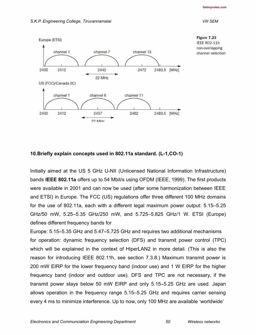
Getmynotes.com
S.K.P. Engineering College, Tiruvannamalai VIII SEM
10.Briefly explain concepts used in 802.11a standard. (L-1,CO-1)
Initially aimed at the US 5 GHz U-NII (Unlicensed National Information Infrastructure)
bands IEEE 802.11a offers up to 54 Mbit/s using OFDM (IEEE, 1999). The first products
were available in 2001 and can now be used (after some harmonization between IEEE
and ETSI) in Europe. The FCC (US) regulations offer three different 100 MHz domains
for the use of 802.11a, each with a different legal maximum power output: 5.15–5.25
GHz/50 mW, 5.25–5.35 GHz/250 mW, and 5.725–5.825 GHz/1 W. ETSI (Europe)
defines different frequency bands for
Europe: 5.15–5.35 GHz and 5.47–5.725 GHz and requires two additional mechanisms
for operation: dynamic frequency selection (DFS) and transmit power control (TPC)
which will be explained in the context of HiperLAN2 in more detail. (This is also the
reason for introducing IEEE 802.11h, see section 7.3.8.) Maximum transmit power is
200 mW EIRP for the lower frequency band (indoor use) and 1 W EIRP for the higher
frequency band (indoor and outdoor use). DFS and TPC are not necessary, if the
transmit power stays below 50 mW EIRP and only 5.15–5.25 GHz are used. Japan
allows operation in the frequency range 5.15–5.25 GHz and requires carrier sensing
every 4 ms to minimize interference. Up to now, only 100 MHz are available ‘worldwide’
Electronics and Communciation Engineering Department 50 Wireless networks
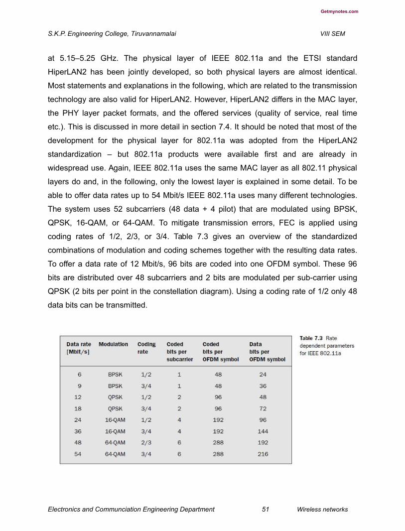
Getmynotes.com
S.K.P. Engineering College, Tiruvannamalai VIII SEM
at 5.15–5.25 GHz. The physical layer of IEEE 802.11a and the ETSI standard
HiperLAN2 has been jointly developed, so both physical layers are almost identical.
Most statements and explanations in the following, which are related to the transmission
technology are also valid for HiperLAN2. However, HiperLAN2 differs in the MAC layer,
the PHY layer packet formats, and the offered services (quality of service, real time
etc.). This is discussed in more detail in section 7.4. It should be noted that most of the
development for the physical layer for 802.11a was adopted from the HiperLAN2
standardization – but 802.11a products were available first and are already in
widespread use. Again, IEEE 802.11a uses the same MAC layer as all 802.11 physical
layers do and, in the following, only the lowest layer is explained in some detail. To be
able to offer data rates up to 54 Mbit/s IEEE 802.11a uses many different technologies.
The system uses 52 subcarriers (48 data + 4 pilot) that are modulated using BPSK,
QPSK, 16-QAM, or 64-QAM. To mitigate transmission errors, FEC is applied using
coding rates of 1/2, 2/3, or 3/4. Table 7.3 gives an overview of the standardized
combinations of modulation and coding schemes together with the resulting data rates.
To offer a data rate of 12 Mbit/s, 96 bits are coded into one OFDM symbol. These 96
bits are distributed over 48 subcarriers and 2 bits are modulated per sub-carrier using
QPSK (2 bits per point in the constellation diagram). Using a coding rate of 1/2 only 48
data bits can be transmitted.
Electronics and Communciation Engineering Department 51 Wireless networks
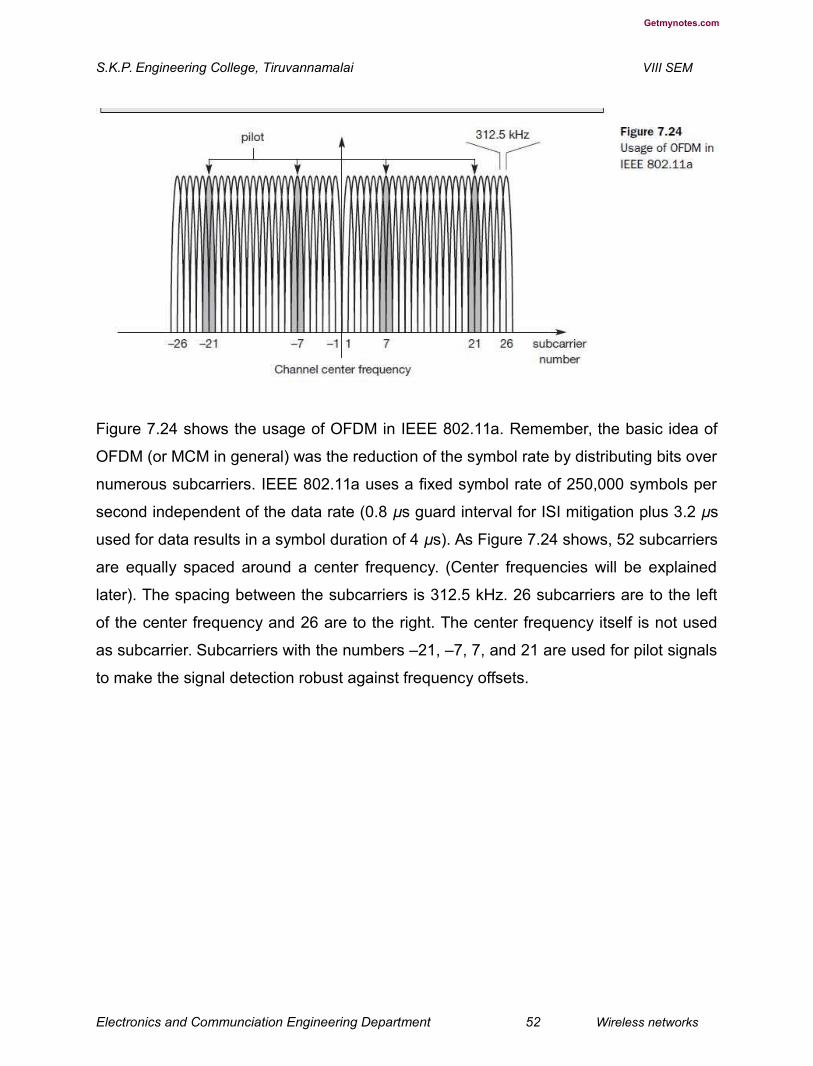
Getmynotes.com
S.K.P. Engineering College, Tiruvannamalai VIII SEM
Figure 7.24 shows the usage of OFDM in IEEE 802.11a. Remember, the basic idea of
OFDM (or MCM in general) was the reduction of the symbol rate by distributing bits over
numerous subcarriers. IEEE 802.11a uses a fixed symbol rate of 250,000 symbols per
second independent of the data rate (0.8 μs guard interval for ISI mitigation plus 3.2 μs
used for data results in a symbol duration of 4 μs). As Figure 7.24 shows, 52 subcarriers
are equally spaced around a center frequency. (Center frequencies will be explained
later). The spacing between the subcarriers is 312.5 kHz. 26 subcarriers are to the left
of the center frequency and 26 are to the right. The center frequency itself is not used
as subcarrier. Subcarriers with the numbers –21, –7, 7, and 21 are used for pilot signals
to make the signal detection robust against frequency offsets.
Electronics and Communciation Engineering Department 52 Wireless networks

Getmynotes.com
S.K.P. Engineering College, Tiruvannamalai VIII SEM
Similar to 802.11b several operating channels have been standardized to minimize
interference. Figure 7.25 shows the channel layout for the US U-NII bands. The center
frequency of a channel is 5000 + 5*channel number [MHz]. This definition provides a
unique numbering of channels with 5 MHz spacing starting from 5 GHz. Depending on
national regulations, different sets of channels may be used. Eight channels have been
defined for the lower two bands in the U-NII (36, 40, 44, 48, 52, 56, 60, and 64); four
more are available in the high band (149, 153, 157, and 161). Using these channels
allows for interference-free operation of overlapping 802.11a cells. Channel spacing is
20 MHz, the occupied bandwidth of 802.11a is 16.6 MHz. How is this related to the
spacing of the sub-carriers? 20 MHz/64 equals 312.5 kHz. 802.11a uses 48 carriers for
data, 4 for pilot signals, and 12 carriers are sometimes called virtual subcarriers. (Set to
zero, they do not contribute to the data transmission but may be used for an
implementation of OFDM with the help of FFT, see IEEE, 1999, or ETSI, 2001a, for
more details). Multiplying 312.5 kHz by 52 subcarriers and adding the extra space for
the center frequency results in approximately 16.6 MHz occupied bandwidth per
channel (details of the transmit spectral power mask neglected, see ETSI, 2001a). Due
to the nature of OFDM, the PDU on the physical layer of IEEE 802.11a looks quite
different from 802.11b or the original 802.11 physical layers. Figure 7.26 shows the
basic structure of an IEEE 802.11a PPDU.
Electronics and Communciation Engineering Department 53 Wireless networks
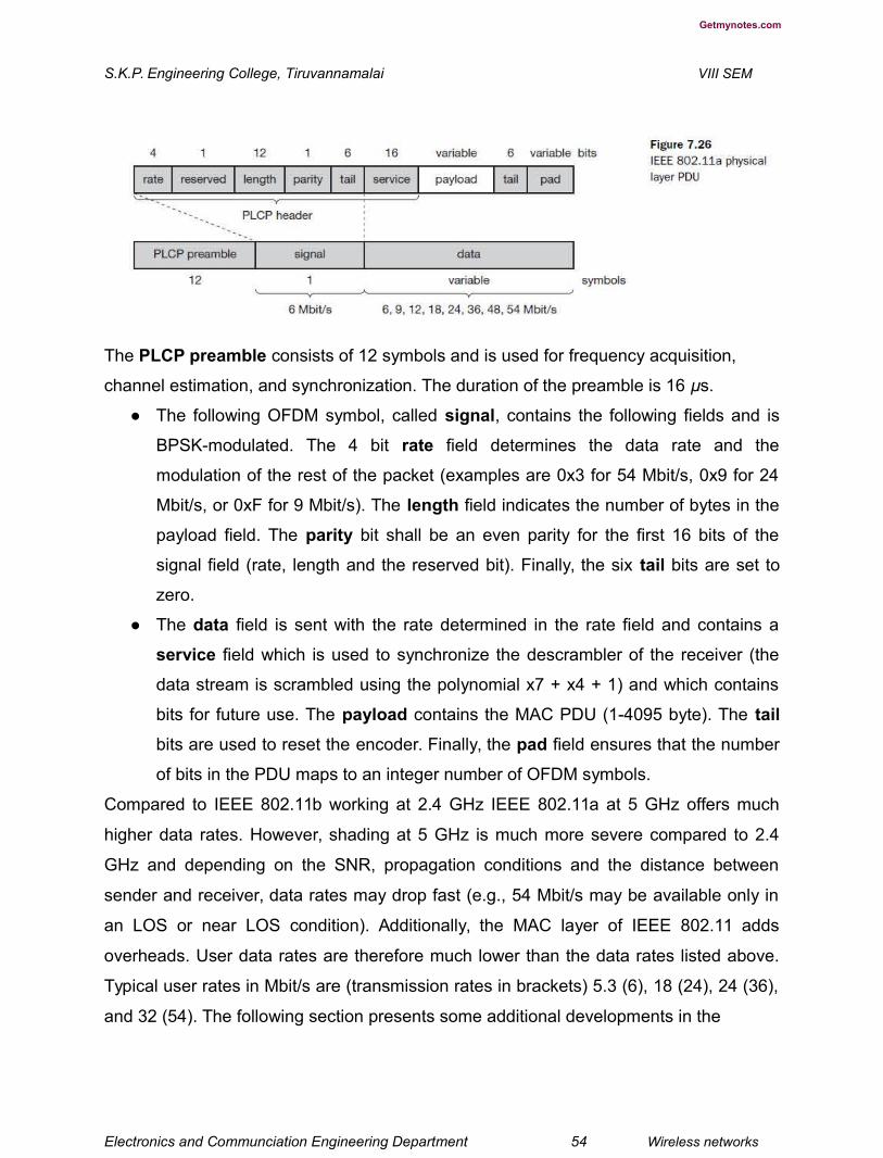
Getmynotes.com
S.K.P. Engineering College, Tiruvannamalai VIII SEM
The PLCP preamble consists of 12 symbols and is used for frequency acquisition,
channel estimation, and synchronization. The duration of the preamble is 16 μs.
● The following OFDM symbol, called signal, contains the following fields and is
BPSK-modulated. The 4 bit rate field determines the data rate and the
modulation of the rest of the packet (examples are 0x3 for 54 Mbit/s, 0x9 for 24
Mbit/s, or 0xF for 9 Mbit/s). The length field indicates the number of bytes in the
payload field. The parity bit shall be an even parity for the first 16 bits of the
signal field (rate, length and the reserved bit). Finally, the six tail bits are set to
zero.
● The data field is sent with the rate determined in the rate field and contains a
service field which is used to synchronize the descrambler of the receiver (the
data stream is scrambled using the polynomial x7 + x4 + 1) and which contains
bits for future use. The payload contains the MAC PDU (1-4095 byte). The tail
bits are used to reset the encoder. Finally, the pad field ensures that the number
of bits in the PDU maps to an integer number of OFDM symbols.
Compared to IEEE 802.11b working at 2.4 GHz IEEE 802.11a at 5 GHz offers much
higher data rates. However, shading at 5 GHz is much more severe compared to 2.4
GHz and depending on the SNR, propagation conditions and the distance between
sender and receiver, data rates may drop fast (e.g., 54 Mbit/s may be available only in
an LOS or near LOS condition). Additionally, the MAC layer of IEEE 802.11 adds
overheads. User data rates are therefore much lower than the data rates listed above.
Typical user rates in Mbit/s are (transmission rates in brackets) 5.3 (6), 18 (24), 24 (36),
and 32 (54). The following section presents some additional developments in the
Electronics and Communciation Engineering Department 54 Wireless networks

Getmynotes.com
S.K.P. Engineering College, Tiruvannamalai VIII SEM
context of 802.11, which also comprise a standard for higher data rates at 2.4 GHz that
can benefit from the better propagation conditions at lower frequencies.
12.Explain the some of the Newer developments in other IEEE standard
protocols.
(H-1,CO-1)
While many products that follow the IEEE 802.11a and 802.11b standards are available,
several new groups have been formed within the IEEE to discuss enhancements of the
standard and new applications. As things change fast, the current status can be
checked via (IEEE, 2002a). The following is only a selection of ongoing work (at the
time of writing). The completed standards IEEE 802.11c and 802.11d cover additions
for bridging support and updates for physical layer
requirements in different regulatory domains (i.e., countries).
● 802.11e (MAC enhancements): Currently, the 802.11 standards offer no quality
of service in the DCF operation mode. Some QoS guarantees can be given, only
via polling using PCF. For applications such as audio, video, or media stream,
distribution service classes have to be provided. For this reason, the MAC layer
must be enhanced compared to the current standard.
● 802.11f (Inter-Access Point Protocol): The current standard only describes the
basic architecture of 802.11 networks and their components. The implementation
of components, such as the distribution system, was deliberately not specified.
Specifications of implementations should generally be avoided as they hinder
improvements. However, a great flexibility in the implementation combined with a
lack of detailed interface definitions and communication protocols, e.g., for
management severely limits the interoperability of devices from different vendors.
For example, seamless roaming between access points of different vendors is
often impossible. 802.11f standardizes the necessary exchange of information
between access points to support the functions of a distribution system.
Electronics and Communciation Engineering Department 55 Wireless networks

Getmynotes.com
S.K.P. Engineering College, Tiruvannamalai VIII SEM
● 802.11g (Data rates above 20 Mbit/s at 2.4 GHz): Introducing new modulation
schemes, forward error correction and OFDM also allows for higher data rates at
2.4 GHz. This approach should be backward compatible to 802.11b and should
benefit from the better propagation characteristics at 2.4 GHz compared to 5
GHz. Currently, chips for 54 Mbit/s are available as well as first products. An
alternative (or additional) proposal for 802.11g suggests the so called packet
binary convolutional coding (PBCC) to reach a data rate of 22 Mbit/s (Heegard,
2001). While the 54 Mbit/s OFDM mode is mandatory, the 22 Mbit/s PBCC mode
can be used as an option. The decision between 802.11a and 802.11g is not
obvious. Many 802.11a products are already available and the 5 GHz band is
(currently) not as crowded as the 2.4 GHz band where not only microwave
ovens, but also Bluetooth, operate (see section 7.5). Coverage is better at 2.4
GHz and fewer access points are needed, lowering the overall system cost.
802.11g access points can also communicate with 802.11b devices as the
current 802.11g products show. Dual mode (or then triple mode) devices will be
available covering 802.11a and b (and g). If a high traffic volume per square
meter is expected (e.g., hot spots in airport terminals), the smaller cells of
802.11a access points and the higher number of available channels (to avoid
interference) at 5 GHz are clear advantages.
802.11h (Spectrum managed 802.11a): The 802.11a standard was primarily designed
for usage in the US U-NII bands. The standardization did not consider non-US
regulations such as the European requirements for power control and dynamic selection
of the transmit frequency. To enable the regulatory acceptance of 5 GHz products,
dynamic channel selection (DCS) and transmit power control (TPC) mechanisms (as
also specified for the European HiperLAN2 standard) have been added. With this
extension, 802.11a products can also be operated in Europe. These additional
mechanisms try to balance the load in the 5 GHz band.
● 802.11i (Enhanced Security mechanisms): As the original security
mechanisms (WEP) proved to be too weak soon after the deployment of the first
products (Borisov, 2001), this working group discusses stronger encryption and
authentication mechanisms. IEEE 802.1x will play a majorrole in this process.

Electronics and Communciation Engineering Department 56 Wireless networks

Getmynotes.com
S.K.P. Engineering College, Tiruvannamalai VIII SEM
Additionally, IEEE 802.11 has several study groups for new and upcoming topics. The
group ‘Radio Resource Measurements’ investigates the possibilities of 802.11 devices
to provide measurements of radio resources. Solutions for even higher throughput are
discussed in the ‘High Throughput’ study group. Both groups had their first meetings in
2002. The first study group recently became the IEEE project 802.11k ‘Radio Resource
Measurement Enhancements.’
13.Evolution of HIPERLAAN and other improvements – Explain in detail (H-3,CO-
1)
In 1996, the ETSI standardized HIPERLAN 1 as a WLAN allowing for node
mobility and supporting ad-hoc and infrastructure-based topologies (ETSI, 1996).
(HIPERLAN stands for high performance local area network.) HIPERLAN 1 was
originally one out of four HIPERLANs envisaged, as ETSI decided to have different
types of networks for different purposes. The key feature of all four networks is their
integration of time-sensitive data transfer services. Over time, names have changed and
the former HIPERLANs 2, 3, and 4 are now
called HiperLAN2, HIPERACCESS, and HIPERLINK. The current focus is on
HiperLAN2, a standard that comprises many elements from ETSI’s BRAN (broadband
radio access networks) and wireless ATM activities. Neither wireless ATM nor
HIPERLAN 1 were a commercial success. However, the standardization efforts had a
lot of impact on QoS supporting wireless broadband networks such as HiperLAN2.
Before describing HiperLAN2 in more detail, the following three sections explain key
features of, and the motivation behind, HIPERLAN 1, wireless ATM, and BRAN.
Electronics and Communciation Engineering Department 57 Wireless networks
Getmynotes.com
S.K.P. Engineering College, Tiruvannamalai VIII SEM
Readers not interested in the historical background may proceed directly to section
7.4.4.
Historical: HIPERLAN 1
ETSI (1998b) describes HIPERLAN 1 as a wireless LAN supporting priorities and
packet life time for data transfer at 23.5 Mbit/s, including forwarding mechanisms,
topology discovery, user data encryption, network identification and power conservation
mechanisms. HIPERLAN 1 should operate at 5.1–5.3 GHz with a range of 50 m in
buildings at 1 W transmit power. The service offered by a HIPERLAN 1 is compatible
with the standard MAC services known from IEEE 802.x LANs. Addressing is based on
standard 48 bit MAC addresses. A special HIPERLAN 1 identification scheme allows the
concurrent operation of two or more physically overlapping HIPERLANs without
mingling their communication. Confidentiality is ensured by an encryption/decryption
algorithm that requires the identical keys and initialization vectors for successful
decryption of a data stream encrypted by a sender.
An innovative feature of HIPERLAN 1, which many other wireless networks do not offer,
is its ability to forward data packets using several relays. Relays can extend the
communication on the MAC layer beyond the radio range. For power conservation, a
node may set up a specific wake-up pattern. This pattern determines at what time the
node is ready to receive, so that at other times, the node can turn off its receiver and
save energy. These nodes are called p-savers and need so-called p-supporters that
contain information about the wake-up patterns of all the p-savers they are responsible
for. A p-supporter only forwards data to a p-saver at the moment the p-saver is awake.
This action also requires buffering mechanisms for packets on p-supporting forwarders.
The following describes only the medium access scheme of HIPERLAN 1, a scheme
that provides QoS and a powerful prioritization scheme. However, it turned out that
priorities and QoS in general are not that important for standard LAN applications today.
IEEE 802.11 in its standard versions does not offer priorities, the optional PCF is
typically not implemented in products – yet 802.11 is very popular.
Electronics and Communciation Engineering Department 58 Wireless networks
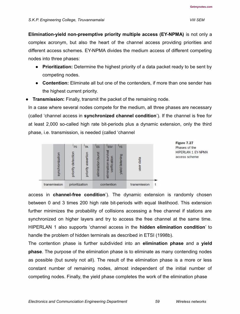
Getmynotes.com
S.K.P. Engineering College, Tiruvannamalai VIII SEM
Elimination-yield non-preemptive priority multiple access (EY-NPMA) is not only a
complex acronym, but also the heart of the channel access providing priorities and
different access schemes. EY-NPMA divides the medium access of different competing
nodes into three phases:
● Prioritization: Determine the highest priority of a data packet ready to be sent by
competing nodes.
● Contention: Eliminate all but one of the contenders, if more than one sender has
the highest current priority.
● Transmission: Finally, transmit the packet of the remaining node.
In a case where several nodes compete for the medium, all three phases are necessary
(called ‘channel access in synchronized channel condition’). If the channel is free for
at least 2,000 so-called high rate bit-periods plus a dynamic extension, only the third
phase, i.e. transmission, is needed (called ‘channel
access in channel-free condition’). The dynamic extension is randomly chosen
between 0 and 3 times 200 high rate bit-periods with equal likelihood. This extension
further minimizes the probability of collisions accessing a free channel if stations are
synchronized on higher layers and try to access the free channel at the same time.
HIPERLAN 1 also supports ‘channel access in the hidden elimination condition’ to
handle the problem of hidden terminals as described in ETSI (1998b).
The contention phase is further subdivided into an elimination phase and a yield
phase. The purpose of the elimination phase is to eliminate as many contending nodes
as possible (but surely not all). The result of the elimination phase is a more or less
constant number of remaining nodes, almost independent of the initial number of
competing nodes. Finally, the yield phase completes the work of the elimination phase
Electronics and Communciation Engineering Department 59 Wireless networks

Getmynotes.com
S.K.P. Engineering College, Tiruvannamalai VIII SEM
with the goal of only one remaining node. Figure 7.27 gives an overview of the three
main phases and some more details which will be explained in the following sections.
For every node ready to send data, the access cycle starts with synchronization to the
current sender. The first phase, prioritization, follows. After that, the elimination and yield
part of the contention phase follow. Finally, the remaining node can transmit its data.
Every phase has a certain duration which is measured in numbers of slots and is
determined by the variables IPS, IPA, IES, IESV, and IYS.
Prioritization phase
HIPERLAN 1 offers five different priorities for data packets ready to be sent. After one
node has finished sending, many other nodes can compete for the right to send. The
first objective of the prioritization phase is to make sure that no node with a lower
priority gains access to the medium while packets with higher priority are waiting at
other nodes. This mechanism always grants nodes with higher priority access to the
medium, no matter how high the load on lower priorities.
In the first step of the prioritization phase, the priority detection, time is divided into five
slots, slot 0 (highest priority) to slot 4 (lowest priority). Each slot has a duration of IPS =
168 high rate bit-periods. If a node has the access priority p, it has to listen into the
medium for p slots (priority detection). If the node senses the medium is idle for the
whole period of p slots, the node asserts
the priority by immediately transmitting a burst for the duration IPA = 168 high rate bit-
periods (priority assertion). The burst consists of the following high rate bit sequence,
which is repeated as many times as necessary for the duration of the
burst:11111010100010011100000110010110
If the node senses activity in the medium, it stops its attempt to send data in this
transmission cycle and waits for the next one. The whole prioritization phase ends as
soon as one node asserts the access priority with a burst. This means that the
prioritization phase is not limited by a fixed length, but depends on the highest priority.
Let us assume, for example, that there are three nodes with data ready to be sent, the
packets of node 1 and node 2 having the priority 2, the packet of node 3 having the
Electronics and Communciation Engineering Department 60 Wireless networks

Getmynotes.com
S.K.P. Engineering College, Tiruvannamalai VIII SEM
priority 4. Then nodes 1, 2 and 3 listen into the medium and sense slots 0 and 1 are
idle. Nodes 1 and 2 both send a burst in slot 2 as priority assertion.
Node 3 stops its attempt to transmit its packet. In this example, the prioritization phase
has taken three slots.After this first phase at least one of the contending nodes will
survive, the surviving nodes being all nodes with the highest priority of this cycle.
Elimination phase
Several nodes may now enter the elimination phase. Again, time is divided into slots,
using the elimination slot interval IES = 212 high rate bit periods. The length of an
individual elimination burst is 0 to 12 slot intervals long, the probability of bursting within
a slot is 0.5. The probability PE(n) of an elimination burst to be n elimination slot
intervals long is given by:
● PE(n) = 0.5n+1 for 0 ≤ n < 12
● PE(n) = 0.512 for n = 12
The elimination phase now resolves contention by means of elimination bursting and
elimination survival verification. Each contending node sends an elimination burst with
length n as determined via the probabilities and then listens to the channel during the
survival verification interval IESV = 256 high rate bit periods. The burst sent is the same
as for the priority assertion. A contending node survives this elimination phase if, and
only if, it senses the channel is idle during its survival verification period. Otherwise, the
node is eliminated and stops its attempt to send data during this transmission cycle. The
whole elimination phase will last for the duration of the longest elimination burst among
the contending nodes plus the survival verification time.
One or more nodes will survive this elimination phase, and can then continue with the
next phase.
Yield phase
During the yield phase, the remaining nodes only listen into the medium without sending
any additional bursts. Again, time is divided into slots, this time called yield slots with a
duration of IYS = 168 high rate bit-periods. The length of an individual yield listening
period can be 0 to 9 slots with equal likelihood. The probability PY(n) for a yield listening
period to be n slots long is 0.1 for all n, 0 ≤ n ≤ 9. Each node now listens for its yield
listening period. If it senses the channel is idle during the whole period, it has survived
Electronics and Communciation Engineering Department 61 Wireless networks
Getmynotes.com
S.K.P. Engineering College, Tiruvannamalai VIII SEM
the yield listening. Otherwise, it withdraws for the rest of the current transmission cycle.
This time, the length of the yield phase is determined by the shortest yield-listening
period among all the contending nodes. At least one node will survive this phase and
can start to transmit data. This is what the other nodes with longer yield listening period
can sense. It is important to note that at this point there can still be more than one
surviving node so a collision is still possible.
Transmission phase
A node that has survived the prioritization and contention phase can now send its data,
called a low bit-rate high bit-rate HIPERLAN 1 CAC protocol data unit (LBR-HBR
HCPDU). This PDU can either be multicast or unicast. In case of a unicast transmission,
the sender expects to receive an immediate acknowledgement from the destination,
called an acknowledgement HCPDU (AK-HCPDU), which is an LBR HCPDU containing
only an LBR part.
Quality of service support and other specialties
The specialty of HIPERLAN 1 is its QoS support. The quality of service offered by the
MAC layer is based on three parameters (HMQoS-parameters). The user can set a
priority for data, priority = 0 denotes a high priority, priority = 1, a low priority. The user
can determine the lifetime of an MSDU to specify time bounded delivery. The MSDU
lifetime specifies the maximum time that can elapse between sending and receiving an
MSDU. Beyond this, delivery of the MSDU becomes unnecessary. The MSDU lifetime
has a range of 0–16,000 ms.
The residual MSDU lifetime shows the remaining lifetime of a packet. Besides data
transfer, the MAC layer offers functions for looking up other HIPERLANs within radio
range as well as special power conserving functions. Power conservation is achieved
by setting up certain recurring patterns when a node can receive data instead of
constantly being ready to receive. Special group-attendance patterns can be defined to
enable multicasting. All nodes participating in a multicast group must be ready to
receive at the same time when a sender transmits data.
HIPERLAN 1 MAC also offers user data encryption and decryption using a simple
XOR-scheme together with random numbers. A key is chosen from a set of keys using a
key identifier (KID) and is used together with an initialization vector IV to initialize the
Electronics and Communciation Engineering Department 62 Wireless networks
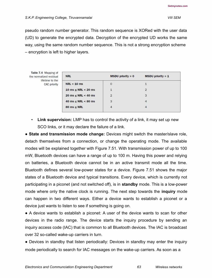
Getmynotes.com
S.K.P. Engineering College, Tiruvannamalai VIII SEM
pseudo random number generator. This random sequence is XORed with the user data
(UD) to generate the encrypted data. Decryption of the encrypted UD works the same
way, using the same random number sequence. This is not a strong encryption scheme
– encryption is left to higher layers.
• Link supervision: LMP has to control the activity of a link, it may set up new
SCO links, or it may declare the failure of a link.
● State and transmission mode change: Devices might switch the master/slave role,
detach themselves from a connection, or change the operating mode. The available
modes will be explained together with Figure 7.51. With transmission power of up to 100
mW, Bluetooth devices can have a range of up to 100 m. Having this power and relying
on batteries, a Bluetooth device cannot be in an active transmit mode all the time.
Bluetooth defines several low-power states for a device. Figure 7.51 shows the major
states of a Bluetooth device and typical transitions. Every device, which is currently not
participating in a piconet (and not switched off), is in standby mode. This is a low-power
mode where only the native clock is running. The next step towards the inquiry mode
can happen in two different ways. Either a device wants to establish a piconet or a
device just wants to listen to see if something is going on.
● A device wants to establish a piconet: A user of the device wants to scan for other
devices in the radio range. The device starts the inquiry procedure by sending an
inquiry access code (IAC) that is common to all Bluetooth devices. The IAC is broadcast
over 32 so-called wake-up carriers in turn.
● Devices in standby that listen periodically: Devices in standby may enter the inquiry
mode periodically to search for IAC messages on the wake-up carriers. As soon as a
Electronics and Communciation Engineering Department 63 Wireless networks

Getmynotes.com
S.K.P. Engineering College, Tiruvannamalai VIII SEM
device detects an inquiry it returns a packet containing its device address and timing
information required by the master to initiate a connection. From that moment on, the
device acts as slave.If the inquiry was successful, a device enters the page mode. The
inquiry phase is not coordinated; inquiry messages and answers to these messages
may collide, so it may take a while before the inquiry is successful. After a while
(typically seconds but sometimes up to a minute) a Bluetooth device sees all the
devices in its radio range. During the page state two different roles are defined. After
finding all required devices the master is able to set up connections to each device, i.e.,
setting up a piconet. Depending on the device addresses received the master calculates
special hopping sequences to contact each device individually. The slaves answer and
synchronize with the master’s clock, i.e., start with the hopping sequence defined by the
master. The master may continue to page more devices that will be added to the
piconet. As soon as a device synchronizes to the hopping pattern of the piconet it also
enters the connection state.The connection state comprises the active state and the low
power states park, sniff, and hold. In the active state the slave participates in the
piconet by listening, transmitting, and receiving. ACL and SCO links can be used. A
master periodically synchronizes with all slaves. All devices being active must have the
3-bit active member address (AMA). Within the active state devices either transmit
data or are simply connected. A device can enter standby again, via a detach
procedure.
To save battery power, a Bluetooth device can go into one of three low power states:
● Sniff state: The sniff state has the highest power consumption of the low power
states. Here, the device listens to the piconet at a reduced rate (not on every
other slot as is the case in the active state). The interval for listening into the
medium can be programed and is application dependent. The master designates
a reduced number of slots for transmission to slaves in sniff state. However, the
device keeps its AMA.
Electronics and Communciation Engineering Department 64 Wireless networks

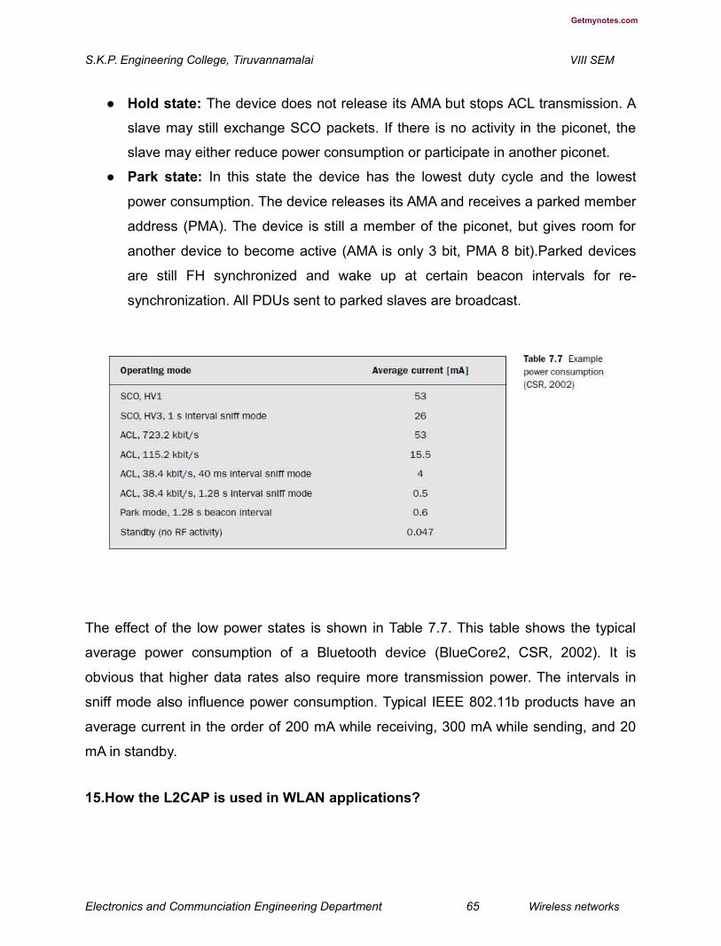
Getmynotes.com
S.K.P. Engineering College, Tiruvannamalai VIII SEM
● Hold state: The device does not release its AMA but stops ACL transmission. A
slave may still exchange SCO packets. If there is no activity in the piconet, the
slave may either reduce power consumption or participate in another piconet.
● Park state: In this state the device has the lowest duty cycle and the lowest
power consumption. The device releases its AMA and receives a parked member
address (PMA). The device is still a member of the piconet, but gives room for
another device to become active (AMA is only 3 bit, PMA 8 bit).Parked devices
are still FH synchronized and wake up at certain beacon intervals for re-
synchronization. All PDUs sent to parked slaves are broadcast.
The effect of the low power states is shown in Table 7.7. This table shows the typical
average power consumption of a Bluetooth device (BlueCore2, CSR, 2002). It is
obvious that higher data rates also require more transmission power. The intervals in
sniff mode also influence power consumption. Typical IEEE 802.11b products have an
average current in the order of 200 mA while receiving, 300 mA while sending, and 20
mA in standby.
15.How the L2CAP is used in WLAN applications?
Electronics and Communciation Engineering Department 65 Wireless networks

Getmynotes.com
S.K.P. Engineering College, Tiruvannamalai VIII SEM
The logical link control and adaptation protocol (L2CAP) is a data link control
protocol on top of the baseband layer offering logical channels between Bluetooth
devices with QoS properties. L2CAP is available for ACLs only. Audio applications using
SCOs have to use the baseband layer directly (see Figure 7.44). L2CAP provides three
different types of logical channels that are transported via the ACL between master and
slave:
● Connectionless: These unidirectional channels are typically used for broadcasts
from a master to its slave(s).
● Connection-oriented: Each channel of this type is bi-directional and supports
QoS flow specifications for each direction. These flow specs follow RFC 1363
(Partridge, 1992) and define average/peak data rate, maximum burst size,
latency, and jitter.
● Signaling: This third type of logical channel is used to exchanging signaling
messages between L2CAP entities.
Each channel can be identified by its channel identifier (CID). Signaling channels
always use a CID value of 1, a CID value of 2 is reserved for connectionless channels.
For connection-oriented channels a unique CID (>= 64) is dynamically assigned at each
end of the channel to identify the connection
(CIDs 3 to 63 are reserved). Figure 7.52 gives an example for logical channels using the
ACL link between master and slave. The master has a bi-directional signaling channel
to each slave. The CID at each end is 1. Additionally, the master maintains a
connectionless, unidirectional channel to both slaves. The CID at the slaves is 2, while
the CID at the beginning of the connectionless channel is dynamically assigned.
Electronics and Communciation Engineering Department 66 Wireless networks


Getmynotes.com
S.K.P. Engineering College, Tiruvannamalai VIII SEM
L2CAP provides mechanisms to add slaves to, and remove slaves from, such a
multicast group. The master has one connection oriented channel to the left slave and
two to the right slave. All CIDs for these channels are dynamically assigned (between
64 and 65535).
Figure 7.53 shows the three packet types belonging to the three logical channel types.
The length field indicates the length of the payload (plus PSM for connectionless
PDUs). The CID has the multiplexing/demultiplexing function as explained above. For
connectionless PDUs a protocol/service multiplexor (PSM) field is needed to identify
the higher layer recipient for the payload. For connection-oriented PDUs the CID
already fulfills this function. Several PSM values have been defined, e.g., 1 (SDP), 3
(RFCOMM), 5 (TCS-BIN).Values above 4096 can be assigned dynamically. The
payload of the signaling PDU contains one or more commands. Each command has its
own code (e.g.,for command reject, connection request, disconnection response etc.)
and an ID that matches a request with its reply. The length field indicates the length of
the data field for this command.
Besides protocol multiplexing, flow specification, and group management, the L2CAP
layer also provides segmentation and reassembly functions. Depending on the
baseband capabilities, large packets have to be chopped into smaller segments. DH5
links, for example, can carry a maximum of 339 bytes while the L2CAP layer accepts up
to 64 kbyte.
Electronics and Communciation Engineering Department 67 Wireless networks

Getmynotes.com
S.K.P. Engineering College, Tiruvannamalai VIII SEM
Security
A radio interface is by nature easy to access. Bluetooth devices can transmit private
data, e.g., schedules between a PDA and a mobile phone. A user clearlydoes not want
another person to eavesdrop the data transfer. Just imagine a scenariowhere two
Bluetooth enabled PDAs in suitcases ‘meet’ on the conveyor belt of an airport
exchanging personal information! Bluetooth offers mechanisms for authentication and
encryption on the MAC layer, which must be implemented in the same way within each
device.
The main security features offered by Bluetooth include a challenge response routine
for authentication, a stream cipher for encryption, and a session key generation. Each
connection may require a one-way, two-way, or no authentication using the challenge-
response routine. All these schemes have to be implemented in silicon, and higher
layers should offer stronger encryption if needed. The security features included in
Bluetooth only help to set up a local domain of trust between devices.
The security algorithms use the public identity of a device, a secret private user key, and
an internally generated random key as input parameters. For each transaction, a new
random number is generated on the Bluetooth chip. Key management is left to higher
layer software.
Electronics and Communciation Engineering Department 68 Wireless networks

Getmynotes.com
S.K.P. Engineering College, Tiruvannamalai VIII SEM
Figure 7.54 shows several steps in the security architecture of Bluetooth. The illustration
is simplified and the interested reader is referred to Bluetooth (2001a) for further details.
The first step, called pairing, is necessary if two Bluetooth devices have never met
before. To set up trust between the two devices a user can enter a secret PIN into both
devices. This PIN can have a length of up to 16 byte. Unfortunately, most devices limit
the length to four digits or, even worse, program
the devices with the fixed PIN ‘0000’ rendering the whole security concept of Bluetooth
questionable at least. Based on the PIN, the device address, and random numbers,
several keys can be computed which can be used as link key for authentication. Link
keys are typically stored in a persistent storage. The authentication is a challenge-
response process based on the link key, a random number generated by a verifier (the
device that requests authentication), and the device address of the claimant (the device
that is authenticated). Based on the link key, values generated during the
authentication, and again a random number an encryption key is generated during the
encryption stage of the security architecture. This key has a maximum size of 128 bits
Electronics and Communciation Engineering Department 69 Wireless networks
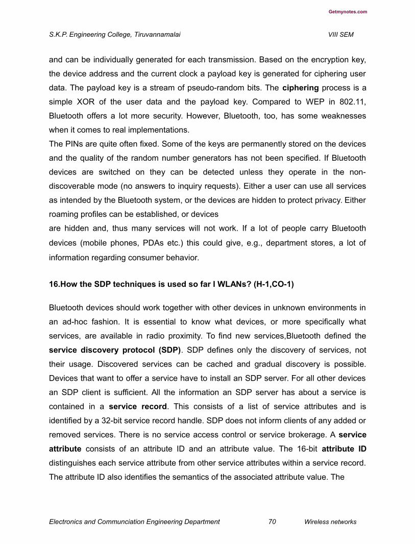
Getmynotes.com
S.K.P. Engineering College, Tiruvannamalai VIII SEM
and can be individually generated for each transmission. Based on the encryption key,
the device address and the current clock a payload key is generated for ciphering user
data. The payload key is a stream of pseudo-random bits. The ciphering process is a
simple XOR of the user data and the payload key. Compared to WEP in 802.11,
Bluetooth offers a lot more security. However, Bluetooth, too, has some weaknesses
when it comes to real implementations.
The PINs are quite often fixed. Some of the keys are permanently stored on the devices
and the quality of the random number generators has not been specified. If Bluetooth
devices are switched on they can be detected unless they operate in the non-
discoverable mode (no answers to inquiry requests). Either a user can use all services
as intended by the Bluetooth system, or the devices are hidden to protect privacy. Either
roaming profiles can be established, or devices
are hidden and, thus many services will not work. If a lot of people carry Bluetooth
devices (mobile phones, PDAs etc.) this could give, e.g., department stores, a lot of
information regarding consumer behavior.
16.How the SDP techniques is used so far I WLANs? (H-1,CO-1)
Bluetooth devices should work together with other devices in unknown environments in
an ad-hoc fashion. It is essential to know what devices, or more specifically what
services, are available in radio proximity. To find new services,Bluetooth defined the
service discovery protocol (SDP). SDP defines only the discovery of services, not
their usage. Discovered services can be cached and gradual discovery is possible.
Devices that want to offer a service have to install an SDP server. For all other devices
an SDP client is sufficient. All the information an SDP server has about a service is
contained in a service record. This consists of a list of service attributes and is
identified by a 32-bit service record handle. SDP does not inform clients of any added or
removed services. There is no service access control or service brokerage. A service
attribute consists of an attribute ID and an attribute value. The 16-bit attribute ID
distinguishes each service attribute from other service attributes within a service record.
The attribute ID also identifies the semantics of the associated attribute value. The
Electronics and Communciation Engineering Department 70 Wireless networks

Getmynotes.com
S.K.P. Engineering College, Tiruvannamalai VIII SEM
attribute value can be an integer, a UUID (universally unique identifier), a string, a
Boolean, a URL (uniform resource locator) etc. Table 7.8 gives some example
attributes. The service handle as well as the ID list must be present. The ID list contains
the UUIDs of the service classes in increasing generality (from the specific color
postscript printer to
printers in general). The protocol descriptor list comprises the protocols needed to
access this service. Additionally, the URLs for service documentation, an icon for the
service and a service name which can be displayed together with the icon are stored in
the example service record.
Profiles
Although Bluetooth started as a very simple architecture for spontaneous ad-hoc
communication, many different protocols, components, extensions, and mechanisms
have been developed over the last years. Application designers and vendors can
implement similar, or even identical, services in many different ways using different
components and protocols from the Bluetooth core standard. To provide compatibility
among the devices offering the same services,Bluetooth specified many profiles in
addition to the core protocols. Without the profiles too many parameters in Bluetooth
would make interoperation between devices from different manufacturers almost
impossible. Profiles represent default solutions for a certain usage model. They use a
Electronics and Communciation Engineering Department 71 Wireless networks
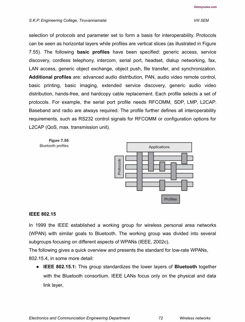
Getmynotes.com
S.K.P. Engineering College, Tiruvannamalai VIII SEM
selection of protocols and parameter set to form a basis for interoperability. Protocols
can be seen as horizontal layers while profiles are vertical slices (as illustrated in Figure
7.55). The following basic profiles have been specified: generic access, service
discovery, cordless telephony, intercom, serial port, headset, dialup networking, fax,
LAN access, generic object exchange, object push, file transfer, and synchronization.
Additional profiles are: advanced audio distribution, PAN, audio video remote control,
basic printing, basic imaging, extended service discovery, generic audio video
distribution, hands-free, and hardcopy cable replacement. Each profile selects a set of
protocols. For example, the serial port profile needs RFCOMM, SDP, LMP, L2CAP.
Baseband and radio are always required. The profile further defines all interoperability
requirements, such as RS232 control signals for RFCOMM or configuration options for
L2CAP (QoS, max. transmission unit).
IEEE 802.15
In 1999 the IEEE established a working group for wireless personal area networks
(WPAN) with similar goals to Bluetooth. The working group was divided into several
subgroups focusing on different aspects of WPANs (IEEE, 2002c).
The following gives a quick overview and presents the standard for low-rate WPANs,
802.15.4, in some more detail:
● IEEE 802.15.1: This group standardizes the lower layers of Bluetooth together
with the Bluetooth consortium. IEEE LANs focus only on the physical and data
link layer,
Electronics and Communciation Engineering Department 72 Wireless networks

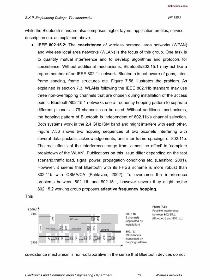
Getmynotes.com
S.K.P. Engineering College, Tiruvannamalai VIII SEM
while the Bluetooth standard also comprises higher layers, application profiles, service
description etc. as explained above.
● IEEE 802.15.2: The coexistence of wireless personal area networks (WPAN)
and wireless local area networks (WLAN) is the focus of this group. One task is
to quantify mutual interference and to develop algorithms and protocols for
coexistence. Without additional mechanisms, Bluetooth/802.15.1 may act like a
rogue member of an IEEE 802.11 network. Bluetooth is not aware of gaps, inter-
frame spacing, frame structures etc. Figure 7.56 illustrates the problem. As
explained in section 7.3, WLANs following the IEEE 802.11b standard may use
three non-overlapping channels that are chosen during installation of the access
points. Bluetooth/802.15.1 networks use a frequency hopping pattern to separate
different piconets – 79 channels can be used. Without additional mechanisms,
the hopping pattern of Bluetooth is independent of 802.11b’s channel selection.
Both systems work in the 2.4 GHz ISM band and might interfere with each other.
Figure 7.56 shows two hopping sequences of two piconets interfering with
several data packets, acknowledgements, and inter-frame spacings of 802.11b.
The real effects of the interference range from ‘almost no effect’ to ‘complete
breakdown of the WLAN’. Publications on this issue differ depending on the test
scenario,traffic load, signal power, propagation conditions etc. (Lansford, 2001).
However, it seems that Bluetooth with its FHSS scheme is more robust than
802.11b with CSMA/CA (Pahlavan, 2002). To overcome the interference
problems between 802.11b and 802.15.1, however severe they might be,the
802.15.2 working group proposes adaptive frequency hopping.
This
coexistence mechanism is non-collaborative in the sense that Bluetooth devices do not
Electronics and Communciation Engineering Department 73 Wireless networks


Getmynotes.com
S.K.P. Engineering College, Tiruvannamalai VIII SEM
have to interact with the WLAN. However, the WPAN devices can check for the
occupied channels and exclude them from their list of channels used for hopping. This
mechanism avoids hopping into a
channel occupied by 802.11b, but still offers enough channels for FHSS.The lower
number of FHSS channels increases the interference among the WPANs due to a
higher probability of collisions. However, if not too many piconets overlap this effect will
be negligible. This type of interference in the crowded 2.4 GHz band is a strong
argument for 5 GHz WLANs.
● IEEE 802.15.3: A high-rate study group looks for a standard providing data rates
of 20 Mbit/s or greater while still working with low-power at low-cost. The
standard should support isochronous data delivery, ad-hoc peer-to-peer
networking, security features, and should meet the demanding requirements of
portable consumer imaging and multi-media applications.
● IEEE 802.15.4: The fourth working group goes in the opposite direction for data
rates. This group standardizes low-rate wireless personal area networks (LR-
WPAN), which are explained in the following section in more detail. TheZigBee
consortium tries to standardize the higher layers of 802.15.4 similar to the
activities of the Bluetooth consortium for 802.15.1 (ZigBee, 2002).
17.Expalin in detail about IEEE 802.15.4 – Low-rate WPANs. (L-1,CO-1)
The reason for having low data rates is the focus of the working group on extremely low
power consumption enabling multi-year battery life (Callaway, 2002). Compared to
802.11 or Bluetooth, the new system should have a much lower complexity making it
suitable for low-cost wireless communication (remember that Bluetooth started with
similar goals with respect to the idea of cable replacement). Example applications
include industrial control and monitoring,
smart badges, interconnection of environmental sensors, interconnection of peripherals
(also an envisaged application area for Bluetooth!), remote controls etc. The new
standard should offer data rates between 20 and 250 kbit/s as maximum and latencies
Electronics and Communciation Engineering Department 74 Wireless networks

Getmynotes.com
S.K.P. Engineering College, Tiruvannamalai VIII SEM
down to 15 ms. This is enough for many home automation and consumer electronics
applications.
IEEE 802.15.4 offers two different PHY options using DSSS. The 868/915 MHz PHY
operates in Europe at 868.0–868.6 MHz and in the US at 902–928 MHz. At 868 MHz
one channel is available offering a data rate of 20 kbit/s. At 915 MHz 10 channels with
40 kbit/s per channel are available (in Europe GSM uses these frequencies). The
advantages of the lower frequencies are better propagation conditions. However, there
is also interference in these bands as many analog
transmission systems use them. The 2.4 GHz PHY operates at 2.4–2.4835 GHz and
offers 16 channels with 250 kbit/s per channel. This PHY offers worldwide operation but
suffers from interference in the 2.4 GHz ISM band and higher propagation loss. Typical
devices with 1 mW output power are expected to cover a 10–20 m range. All PHY PDUs
start with a 32 bit preamble for synchronization. After a start-of-packet delimiter, the
PHY header indicates the length of the payload (maximum 127 bytes).
Compared to Bluetooth the MAC layer of 802.15.4 is much simpler. For example, no
synchronous voice links are supported. MAC frames start with a 2-byte frame control
field, which specifies how the rest of the frame looks and what it contains. The following
1-byte sequence number is needed to match acknowledgements with a previous data
transmission. The variable address field (0–20 bytes) may contain source and/or
destination addresses in various formats.
The payload is variable in length; however, the whole MAC frame may not exceed 127
bytes in length. A 16-bit FCS protects the frame. Four different MAC frames have been
defined: beacon, data, acknowledgement, and MAC command. Optionally, this LR-
WPAN offers a superframe mode. In this mode, a PAN coordinator transmits beacons
in predetermined intervals (15 ms–245 s). With the help of beacons, the medium access
scheme can have a period when contention
is possible and a period which is contention free. Furthermore, with beacons a slotted
CSMA/CA is available. Without beacons standard CSMA/CA is used for medium
access. Acknowledgement frames confirming a previous transmission do not use the
CSMA mechanism. These frames are sent immediately following the previous packet.
Electronics and Communciation Engineering Department 75 Wireless networks
Getmynotes.com
S.K.P. Engineering College, Tiruvannamalai VIII SEM
IEEE 802.15.4 specifies three levels of security: no security, access control lists, and
symmetric encryption using AES-128. Key distribution is not specified further. Security is
a must for home automation or industry control applications. Up to now, the success of
this standard is unclear as it is squeezed between Bluetooth, which also aims at cable
replacement, and enhanced RFIDs/RF controllers.
UNIT II
PART A
1.What do you meant by topologically correct address ? (L-1,CO-2)
A router would otherwise have to store the addresses of all computers in the
internet, which is obviously not feasible. As long as the receiver can be reached within
its physical subnet, it gets the packets; as soon as it moves outside the subnet, a packet
will not reach it. A host needs a so-called topologically correct address.
2.Give the significance of socket pair. (L-3,CO-2)
A TCP connection is identified by the tuple (source IP address, source port,
destination IP address, destination port), also known as a socket pair (a socket
consists of address and port). Therefore, a TCP connection cannot survive any address
change. Breaking TCP connections is not an option, using even simple programs like
telnet would be impossible. The mobile node would also have to notify all
communication partners about the new address.
Electronics and Communciation Engineering Department 76 Wireless networks

Getmynotes.com
S.K.P. Engineering College, Tiruvannamalai VIII SEM
3.Give short notes about Mobile Node. (L-1,CO-2)
A mobile node is an end-system or router that can change its point of attachment
to the internet using mobile IP. The MN keeps its IP address and can continuously
communicate with any other system in the internet as long as link-layer connectivity is
given. Mobile nodes are not necessarily small devices such as laptops with antennas or
mobile phones; a router onboard an aircraft can be a powerful mobile node.
4.Explain in your point of view about care of address. (L-1,CO-2)
The COA defines the current location of the MN from an IP point of view. All IP
packets sent to the MN are delivered to the COA, not directly to the IP address of
the MN. Packet delivery toward the MN is done using a tunnel, as explained later.
To be more precise, the COA marks the tunnel endpoint, i.e., the address where
packets exit the tunnel.
5. How the Host agent acts as manager in the routing? (H-1,CO-2)
If changing the router’s software is not possible, the HA could also be
implemented on an arbitrary node in the subnet. One disadvantage of this solution is the
double crossing of the router by the packet if the MN is in a foreign network. A packet for
the MN comes in via the router; the HA sends it through the tunnel which again crosses
the Finally, a home network is not necessary at all. The HA could be again on the
‘router’ but this time only acting as a manager for MNs belonging to a virtual home
network. All MNs are always in a foreign network with this solution.
6. How tunneling helps to deliver the packets in networking? (H-2,CO-2)
A tunnel establishes a virtual pipe for data packets between a tunnel entry and a
tunnel endpoint. Packets entering a tunnel are forwarded inside the tunnel and leave the
tunnel unchanged. Tunneling, i.e., sending a packet through a tunnel, is achieved by
using encapsulation.
Electronics and Communciation Engineering Department 77 Wireless networks

Getmynotes.com
S.K.P. Engineering College, Tiruvannamalai VIII SEM
7. Give the Difference between Encapsulation& decapsulation. (L-1,CO-2)
Encapsulation is the mechanism of taking a packet consisting of packet header
and data and putting it into the data part of a new packet. The reverse operation, taking
a packet out of the data part of another packet, is called decapsulation. Encapsulation
and decapsulation are the operations typically performed when a packet is transferred
from a higher protocol layer to a lower layer or from a lower to a higher layer
respectively. Here these functions are used within the same layer.
8. How the offset respresenting the ruting techniques? (L-2,CO-2)
The offset represents the offset in bytes for the first source routing entry. The
routing field, if present, has a variable length and contains fields for source routing.
9.How the recursion control field works? (L-3,CO-2)
The recursion control field (rec.) is an important field that additionally
distinguishes GRE from IP-in-IP and minimal encapsulation. This field represents a
counter that shows the number of allowed recursive encapsulations.
10. How The Triangular Protocol Works? (H-1,CO-2)
The triangle is made of the three segments, CN to HA, HA to COA/MN, and MN
back to CN. With the basic mobile IP protocol all packets to the MN have to go through
the HA. This can cause unnecessary overheads for the network between CN and HA,
but also between HA and COA, depending on the current location of theMN.
11. Draw The Example For Weak Link And Strong Link Adhoc Network. (L-1,CO-2)
Electronics and Communciation Engineering Department 78 Wireless networks

Getmynotes.com
S.K.P. Engineering College, Tiruvannamalai VIII SEM
12.What Do You Meant By Destination sequence distance vector? (L-1,CO-2)
Destination sequence distance vector (DSDV) routing is an enhancement todistance vector routing for ad-hoc networks (Perkins, 1994). DSDV can be consideredhistorically, however, an on-demand version (ad-hoc on-demand distance vector,AODV) is among the protocols
13.Give The Disadvantage Of Proactive Schemes. (L-1,CO-2)
A big disadvantage of proactive schemes are their overheads in lightly loaded
networks. Independent of any real communication the algorithm continuously updates
the routing tables. This generates a lot of unnecessary traffic and drains the batteries of
mobile devices.
PART B
1.Explain in detail about Mobile IP. (L-1,CO-2)
The following gives an overall view of Mobile IP, and the extensions needed for the
internet to support the mobility of hosts. A good reference for the original standard (RFC
2002, Perkins, 1996a) is Perkins (1997) and Solomon (1998) which describe the
development of mobile IP, all packet formats, mechanisms, discussions of the protocol
and alternatives etc. in detail. The new version of Mobile IP does not involve major
changes in the basic architecture but corrects some minor problems (RFC 3344,
Perkins, 2002). The following material requires some familiarity with Internet protocols,
especially IP. A very good overview which includes detailed descriptions of classical
Internet protocols is given in Stevens (1994). Many new approaches related to Internet
protocols, applications, and architectures can be found in Kurose (2003).
Goals, assumptions and requirements
Electronics and Communciation Engineering Department 79 Wireless networks
Getmynotes.com
S.K.P. Engineering College, Tiruvannamalai VIII SEM
As shown , mobile computing is clearly the paradigm of the future. The internet is the
network for global data communication with hundreds of millions of users. So why not
simply use a mobile computer in the internet? The reason is quite simple: you will not
receive a single packet as soon as you leave your home network, i.e., the network your
computer is configured for, and reconnect your computer (wireless or wired) at another
place (if no additional mechanisms are available). The reason for this is quite simple if
you consider routing mechanisms on the internet. A host sends an IP packet with the
header containing a destination address with other fields. The destination address not
only determines the receiver of the packet, but also the physical subnet of the receiver.
For example, the destination address 129.13.42.99 shows that the receiver must be
connected to the physical subnet with the network prefix 129.13.42 (unless CIDR is
used, RFC 1519, Fuller, 1993). Routers in the internet now look at the destination
addresses of incoming packets and forward them according to internal look-up tables.
To avoid an explosion of routing tables, only prefixes are stored and further
optimizations are applied. A router would otherwise have to store the addresses of all
computers in the internet,
which is obviously not feasible. As long as the receiver can be reached within its
physical subnet, it gets the packets; as soon as it moves outside the subnet, a packet
will not reach it. A host needs a so-called topologically correct address. Quick
‘solutions’
One might think that a quick solution to this problem would be to assign to the computer
a new, topologically correct IP address. This is what many users do with the help of
DHCP (see section 8.2). So moving to a new location would mean assigning a new IP
address. The problem is that nobody knows about this new address. It is almost
impossible to find a (mobile) host on the internet which has just changed its address.
One could argue that with the help of dynamic DNS (DDNS, RFC 2136, Vixie, 1997) an
update of the mapping logical name – IP address is possible. This is what many
computer users do if they have a dynamic IP address and still want to be permanently
reachable using the same logical computer name. It is important to note that these
considerations, indeed most of mobile IP’s motivation, are important if a user wants to
offer services from a mobile node, i.e., the node should act as server. Typically, the IP
Electronics and Communciation Engineering Department 80 Wireless networks

Getmynotes.com
S.K.P. Engineering College, Tiruvannamalai VIII SEM
address is of no special interest for service usage: in this case DHCP is sufficient.
Another motivation for permanent IP addresses is emergency communication with
permanent and quick reachability via the same IP address. So what about dynamically
adapting the IP address with regard to the current location? The problem is that the
domain name system (DNS) needs some time before it updates the internal tables
necessary to map a logical name to an IP address. This approach does not work if the
mobile node moves quite often. The internet and DNS have not been built for frequent
updates. Just imagine millions of nodes moving at the same time. DNS could never
present a consistent view of names and addresses, as it uses caching to improve
scalability. It is simply too expensive to update quickly.
There is a severe problem with higher layer protocols like TCP which rely on IP
addresses. Changing the IP address while still having a TCP connection open means
breaking the connection. A TCP connection is identified by the tuple (source IP address,
source port, destination IP address, destination port), also known as a socket pair (a
socket consists of address and port). Therefore, a TCP connection cannot survive any
address change. Breaking TCP connections is not an option, using even simple
programs like telnet would be impossible. The mobile node would also have to notify all
communication partners about the new address.
Another approach is the creation of specific routes to the mobile node. Routers always
choose the best-fitting prefix for the routing decision. If a router now has an entry for a
prefix 129.13.42 and an address 129.13.42.99, it would choose the port associated with
the latter for forwarding, if a packet with the destination address 129.13.42.99 comes in.
While it is theoretically possible to
change routing tables all over the world to create specific routes to a mobile node, this
does not scale at all with the number of nodes in the internet. Routers are built for
extremely fast forwarding, but not for fast updates of routing tables. While the first is
done with special hardware support, the latter is typically a piece of software which
cannot handle the burden of frequent updates. Routers are the ‘brains’ of the internet,
holding the whole net together. No service provider or system administrator would allow
changes to the routing tables, probably sacrificing stability, just to provide mobility for
individual users.
Electronics and Communciation Engineering Department 81 Wireless networks

Getmynotes.com
S.K.P. Engineering College, Tiruvannamalai VIII SEM
2. Explain the Requirements of Mobile IP. (L-3,CO-2)
Since the quick ‘solutions’ obviously did not work, a more general architecture had to be
designed. Many field trials and proprietary systems finally led to mobile IP as a standard
to enable mobility in the internet. Several requirements accompanied the development
of the standard:
● Compatibility: The installed base of Internet computers, i.e., computers running
TCP/IP and connected to the internet, is huge. A new standard cannot introduce
changes for applications or network protocols already in use. People still want to
use their favorite browser for www and do not want to change applications just
for mobility, the same holds for operating systems. Mobile IP has to be integrated
into existing operating systems or at least work with them (today it is available for
many platforms). Routers within the internet should not necessarily require other
software. While it is possible to enhance the capabilities of some routers to
support mobility,it is almost impossible to change all of them. Mobile IP has to
remain compatible with all lower layers used for the standard, non-mobile, IP.
Mobile IP must not require special media or MAC/LLC protocols, so it must use
the same interfaces and mechanisms to access the lower layers as IP does.
Finally, end-systems enhanced with a mobile IP implementation should still be
able to communicate with fixed systems without mobile IP. Mobile IP has to
ensure that users can still access all the other servers and systems in the
internet. But that implies using the same address format and routing
mechanisms.
● Transparency: Mobility should remain ‘invisible’ for many higher layer protocols
and applications. Besides maybe noticing a lower bandwidth and some
interruption in service, higher layers should continue to work even if the mobile
computer has changed its point of attachment to the network.
For TCP this means that the computer must keep its IP address as explained above. If
the interruption of the connectivity does not take too long, TCP connections survive the
change of the attachment point. Problems related to the performance of TCP are
discussed. Clearly, many of today’s applications have not been designed for use in
mobile environments, so the only effects of mobility should be a higher delay and lower
bandwidth. However, there are some applications for which it is better to be ‘mobility

Electronics and Communciation Engineering Department 82 Wireless networks
Getmynotes.com
S.K.P. Engineering College, Tiruvannamalai VIII SEM
aware’. Examples are cost-based routing or video compression. Knowing that it is
currently possible to use different networks, the software could choose the cheapest
one. Or if a video application knows that only a low bandwidth connection is currently
available, it could use a different compression scheme. Additional mechanisms are
necessary to inform these applications about mobility (Brewer, 1998).
● Scalability and efficiency: Introducing a new mechanism to the internet must
not jeopardize its efficiency. Enhancing IP for mobility must not generate too
many new messages flooding the whole network. Special care has to be taken
considering the lower bandwidth of wireless links. Many mobile systems will have
a wireless link to an attachment point, so only some additional packets should be
necessary between a mobile system and a node in the network. Looking at the
number of computers connected to the internet and at the growth rates of mobile
communication, it is clear that myriad devices will participate in the internet as
mobile components. Just think of cars, trucks, mobile phones, every seat in every
plane around the world etc. – many of them will have some IP implementation
inside and move between different networks and require mobile IP. It is crucial for
a mobile IP to be scalable over a large number of participants in the whole
internet, worldwide.
● Security: Mobility poses many security problems. The minimum requirement is
that of all the messages related to the management of Mobile IP are
authenticated. The IP layer must be sure that if it forwards a packet to a mobile
host that this host receives the packet. The IP layer can only guarantee that the
IP address of the receiver is correct. There are no ways of preventing fake IP
addresses or other attacks. According to Internet philosophy, this is left to higher
layers (keep the core of the internet simple, push more complex services to the
edge).
The goal of a mobile IP can be summarized as: ‘supporting end-system mobility while
maintaining scalability, efficiency, and compatibility in all respects with existing
applications and Internet protocols’.
3. How the Entities and terminology of mobile networks? (L-1,CO-2)

Electronics and Communciation Engineering Department 83 Wireless networks

Getmynotes.com
S.K.P. Engineering College, Tiruvannamalai VIII SEM
The following defines several entities and terms needed to understand mobile IP as
defined in RFC 3344 (Perkins, 2002; was: RFC 2002, Perkins, 1996a). Figure 8.1
illustrates an example scenario.
● Mobile node (MN): A mobile node is an end-system or router that can change its
point of attachment to the internet using mobile IP. The MN keeps its IP address
and can continuously communicate with any other system in the internet as long
as link-layer connectivity is given. Mobile nodes are not necessarily small devices
such as laptops with antennas or mobile phones; a router onboard an aircraft can
be a powerful mobile node.
Correspondent node (CN): At least one partner is needed for communication.
In the following the CN represents this partner for the MN. The CN can be a fixed or
mobile node.
● Home network: The home network is the subnet the MN belongs to with respect
to its IP address. No mobile IP support is needed within the home network.
● Foreign network: The foreign network is the current subnet the MN visits and
which is not the home network.
● Foreign agent (FA): The FA can provide several services to the MN during its
visit to the foreign network. The FA can have the COA (defined below), acting as
tunnel endpoint and forwarding packets to the MN. The FA can be the default
router for the MN. FAs can also provide security services because they belong to
the foreign network as opposed to the MN which is only visiting.
For mobile IP functioning, FAs are not necessarily needed. Typically, an FA is
implemented on a router for the subnet the MN attaches to.
Electronics and Communciation Engineering Department 84 Wireless networks
Getmynotes.com
S.K.P. Engineering College, Tiruvannamalai VIII SEM
● Care-of address (COA): The COA defines the current location of the MN from
an IP point of view. All IP packets sent to the MN are delivered to the COA, not
directly to the IP address of the MN. Packet delivery toward the MN is done using
a tunnel, as explained later. To be more precise, the COA marks the tunnel
endpoint, i.e., the address where packets exit the tunnel.
There are two different possibilities for the location of the COA:
● Foreign agent COA: The COA could be located at the FA, i.e., the COA is an IP
address of the FA. The FA is the tunnel end-point and forwards packets to the
MN. Many MN using the FA can share this COA as common COA.
● Co-located COA: The COA is co-located if the MN temporarily acquired an
additional IP address which acts as COA. This address is now topologically
correct, and the tunnel endpoint is at the MN. Co-located addresses can be
acquired using services such as DHCP (see section 8.2). One problem
associated with this approach is the need for additional addresses if MNs request
a COA. This is not always a good idea considering the scarcity of IPv4
addresses.
● Home agent (HA): The HA provides several services for the MN and is located
in the home network. The tunnel for packets toward the MN starts at the HA. The
HA maintains a location registry, i.e., it is informed of the MN’s location by the
current COA. Three alternatives for the implementation of an HA exist.
● The HA can be implemented on a router that is responsible for the home
network. This is obviously the best position, because without optimizations to
mobile IP, all packets for the MN have to go through the router anyway.
● If changing the router’s software is not possible, the HA could also be
implemented on an arbitrary node in the subnet. One disadvantage of this
solution is the double crossing of the router by the packet if the MN is in a foreign
network. A packet for the MN comes in via the router; the HA sends it through the
tunnel which again crosses the Finally, a home network is not necessary at all.
The HA could be again on the ‘router’ but this time only acting as a manager for
MNs belonging to a virtual home network. All MNs are always in a foreign
network with this solution.
The example network in Figure 8.1 shows the following situation: A CN is connected via
a router to the internet, as are the home network and the foreign network. The HA is

Electronics and Communciation Engineering Department 85 Wireless networks

Getmynotes.com
S.K.P. Engineering College, Tiruvannamalai VIII SEM
implemented on the router connecting the home network with the internet, an FA is
implemented on the router to the foreign network. The MN is currently in the foreign
network. The tunnel for packets toward the
MN starts at the HA and ends at the FA, for the FA has the COA in this example.
4. How the IP packet delivery is achieved in WLAN? (H-1,CO-2)
Figure 8.2 illustrates packet delivery to and from the MN using the example network of
Figure 8.1. A correspondent node CN wants to send an IP packet to the MN. One of the
requirements of mobile IP was to support hiding the mobility of the MN. CN does not
need to know anything about the MN’s current location and sends the packet as usual
to the IP address of MN (step 1). This means that CN sends an IP packet with MN as a
destination address and CN as a source address. The internet, not having information
on the current location of MN, routes the packet to the router responsible for the home
network of MN. This is
done using the standard routing mechanisms of the internet. The HA now intercepts the
packet, knowing that MN is currently not in its home network. The packet is not
forwarded into the subnet as usual, but encapsulated and tunnelled to the COA. A new
header is put in front of the old IP header showing the COA as new destination and HA
as source of the encapsulated packet (step 2). (Tunneling and encapsulation is
described in more detail in section 8.1.6.) The foreign agent now decapsulates the
packet, i.e., removes the additional header, and forwards the original packet with CN as
source and MN as destination to the MN (step 3). Again, for the MN mobility is not
visible. It receives the packet with the same sender and receiver address as it would
have
done in the home network.
Electronics and Communciation Engineering Department 86 Wireless networks
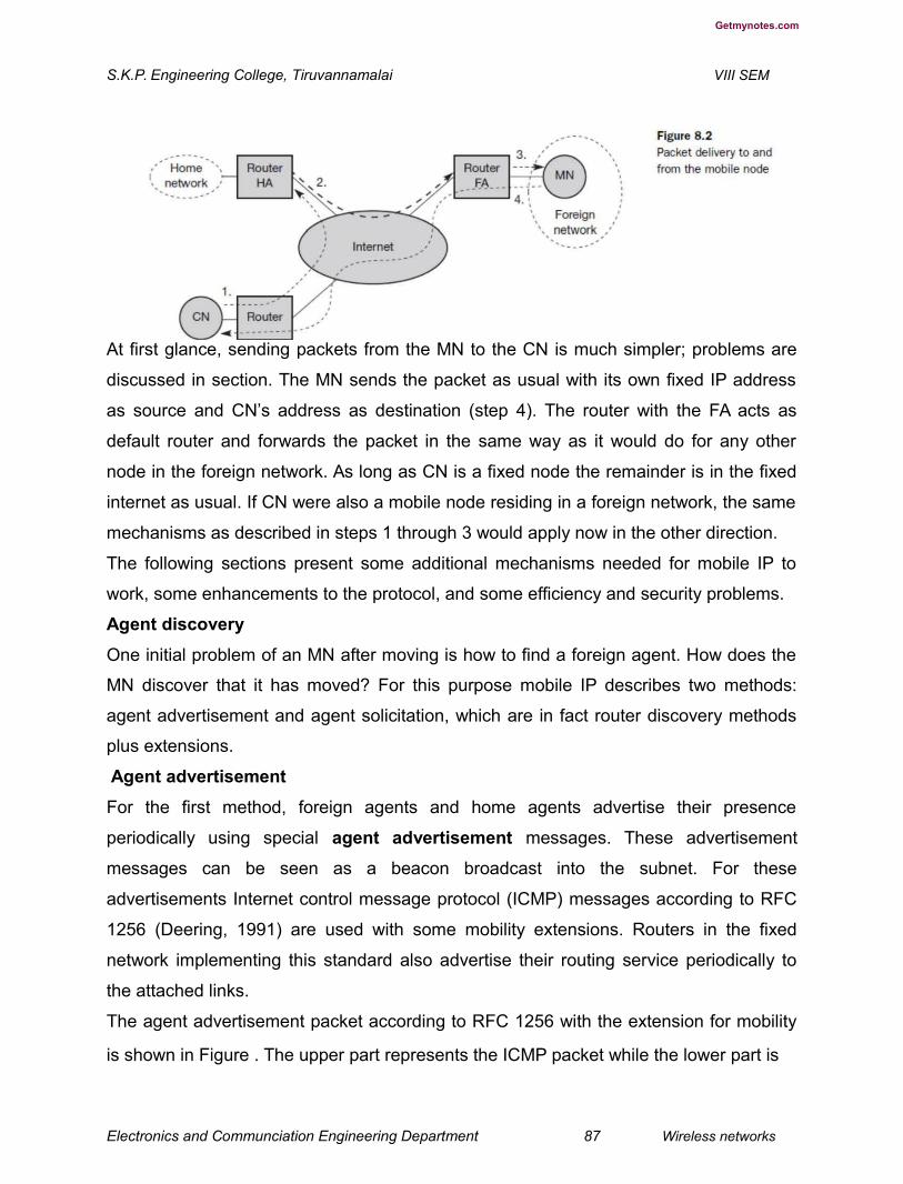
Getmynotes.com
S.K.P. Engineering College, Tiruvannamalai VIII SEM
At first glance, sending packets from the MN to the CN is much simpler; problems are
discussed in section. The MN sends the packet as usual with its own fixed IP address
as source and CN’s address as destination (step 4). The router with the FA acts as
default router and forwards the packet in the same way as it would do for any other
node in the foreign network. As long as CN is a fixed node the remainder is in the fixed
internet as usual. If CN were also a mobile node residing in a foreign network, the same
mechanisms as described in steps 1 through 3 would apply now in the other direction.
The following sections present some additional mechanisms needed for mobile IP to
work, some enhancements to the protocol, and some efficiency and security problems.
Agent discovery
One initial problem of an MN after moving is how to find a foreign agent. How does the
MN discover that it has moved? For this purpose mobile IP describes two methods:
agent advertisement and agent solicitation, which are in fact router discovery methods
plus extensions.
Agent advertisement
For the first method, foreign agents and home agents advertise their presence
periodically using special agent advertisement messages. These advertisement
messages can be seen as a beacon broadcast into the subnet. For these
advertisements Internet control message protocol (ICMP) messages according to RFC
1256 (Deering, 1991) are used with some mobility extensions. Routers in the fixed
network implementing this standard also advertise their routing service periodically to
the attached links.
The agent advertisement packet according to RFC 1256 with the extension for mobility
is shown in Figure . The upper part represents the ICMP packet while the lower part is
Electronics and Communciation Engineering Department 87 Wireless networks

Getmynotes.com
S.K.P. Engineering College, Tiruvannamalai VIII SEM
the extension needed for mobility. The fields necessary on lower layers for the agent
advertisement are not shown in this figure. Clearly, mobile nodes must be reached with
the appropriate link layer address. The TTL field of the IP packet is set to 1 for all
advertisements to avoid forwarding them. The IP destination address according to
standard router advertisements can be either set to 224.0.0.1, which is the multicast
address for all systems on a link (Deering, 1989), or to the broadcast address
255.255.255.255. The fields in the ICMP part are defined as follows. The type is set to
9, the code can be 0, if the agent also routes traffic from non-mobile nodes, or 16, if it
does not route anything other than mobile traffic. Foreign agents are at least required to
forward packets from the mobile node. The number of addresses advertised with this
packet is in #addresses while the addresses themselves follow as shown. Lifetime
denotes the length of time this advertisement is valid. Preference levels for each
address help a node to choose the router that is the most eager one to get a new node.
The difference compared with standard ICMP advertisements is what happens after the
router addresses. This extension for mobility has the following fields defined: type is set
to 16, length depends on the number of COAs provided with the message and equals 6
+ 4*(number of addresses). An agent shows the total number of advertisements sent
Electronics and Communciation Engineering Department 88 Wireless networks
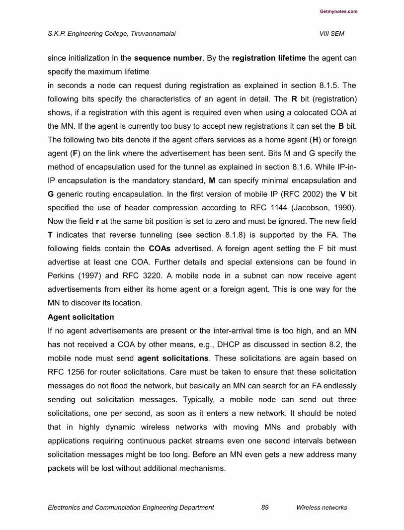
Getmynotes.com
S.K.P. Engineering College, Tiruvannamalai VIII SEM
since initialization in the sequence number. By the registration lifetime the agent can
specify the maximum lifetime
in seconds a node can request during registration as explained in section 8.1.5. The
following bits specify the characteristics of an agent in detail. The R bit (registration)
shows, if a registration with this agent is required even when using a colocated COA at
the MN. If the agent is currently too busy to accept new registrations it can set the B bit.
The following two bits denote if the agent offers services as a home agent (H) or foreign
agent (F) on the link where the advertisement has been sent. Bits M and G specify the
method of encapsulation used for the tunnel as explained in section 8.1.6. While IP-in-
IP encapsulation is the mandatory standard, M can specify minimal encapsulation and
G generic routing encapsulation. In the first version of mobile IP (RFC 2002) the V bit
specified the use of header compression according to RFC 1144 (Jacobson, 1990).
Now the field r at the same bit position is set to zero and must be ignored. The new field
T indicates that reverse tunneling (see section 8.1.8) is supported by the FA. The
following fields contain the COAs advertised. A foreign agent setting the F bit must
advertise at least one COA. Further details and special extensions can be found in
Perkins (1997) and RFC 3220. A mobile node in a subnet can now receive agent
advertisements from either its home agent or a foreign agent. This is one way for the
MN to discover its location.
Agent solicitation
If no agent advertisements are present or the inter-arrival time is too high, and an MN
has not received a COA by other means, e.g., DHCP as discussed in section 8.2, the
mobile node must send agent solicitations. These solicitations are again based on
RFC 1256 for router solicitations. Care must be taken to ensure that these solicitation
messages do not flood the network, but basically an MN can search for an FA endlessly
sending out solicitation messages. Typically, a mobile node can send out three
solicitations, one per second, as soon as it enters a new network. It should be noted
that in highly dynamic wireless networks with moving MNs and probably with
applications requiring continuous packet streams even one second intervals between
solicitation messages might be too long. Before an MN even gets a new address many
packets will be lost without additional mechanisms.
Electronics and Communciation Engineering Department 89 Wireless networks

Getmynotes.com
S.K.P. Engineering College, Tiruvannamalai VIII SEM
If a node does not receive an answer to its solicitations it must decrease the rate of
solicitations exponentially to avoid flooding the network until it reaches a maximum
interval between solicitations (typically one minute). Discovering a new agent can be
done anytime, not just if the MN is not connected to one. Consider the case that an MN
is looking for a better connection while still sending via the old path. This is the case
while moving through several cells of different wireless networks. After these steps of
advertisements or solicitations the MN can now receive a COA, either one for an FA or a
co-located COA. The MN knows its location (home network or foreign network) and the
capabilities of the agent (if needed). The next step for the MN is the registration with the
HA if the MN is in a foreign network as described in the following.
Registration
Having received a COA, the MN has to register with the HA. The main purpose of the
registration is to inform the HA of the current location for correct forwarding of packets.
Registration can be done in two different ways depending on the location of the COA.
● If the COA is at the FA, registration is done as illustrated in Figure 8.4 (left). The
MN sends its registration request containing the COA (see Figure 8.5) to the FA
which is forwarding the request to the HA. The HA now sets up a mobility
binding containing the mobile node’s home IP address and the current COA.
Additionally, the mobility binding contains the lifetime of the registration which is
negotiated during the registration process. Registration expires automatically
after the lifetime and is deleted; so, an MN should reregister before expiration.
This mechanism is necessary to avoid mobility bindings which are no longer
used. After setting up the mobility binding, the HA sends a reply message back to
the FA which forwards it to the MN.
● If the COA is co-located, registration can be simpler, as shown in Figure 8.4
(right). The MN may send the request directly to the HA and vice versa. This, by
the way, is also the registration procedure for MNs returning to their home
network. Here they also register directly with the HA. However, if the MN
received an agent advertisement from the FA it should register via
this FA if the R bit is set in the advertisement.
Electronics and Communciation Engineering Department 90 Wireless networks

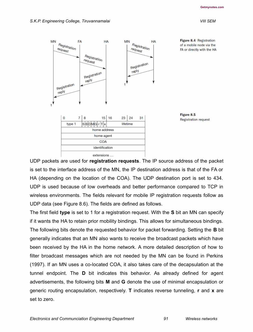
Getmynotes.com
S.K.P. Engineering College, Tiruvannamalai VIII SEM
UDP packets are used for registration requests. The IP source address of the packet
is set to the interface address of the MN, the IP destination address is that of the FA or
HA (depending on the location of the COA). The UDP destination port is set to 434.
UDP is used because of low overheads and better performance compared to TCP in
wireless environments. The fields relevant for mobile IP registration requests follow as
UDP data (see Figure 8.6). The fields are defined as follows.
The first field type is set to 1 for a registration request. With the S bit an MN can specify
if it wants the HA to retain prior mobility bindings. This allows for simultaneous bindings.
The following bits denote the requested behavior for packet forwarding. Setting the B bit
generally indicates that an MN also wants to receive the broadcast packets which have
been received by the HA in the home network. A more detailed description of how to
filter broadcast messages which are not needed by the MN can be found in Perkins
(1997). If an MN uses a co-located COA, it also takes care of the decapsulation at the
tunnel endpoint. The D bit indicates this behavior. As already defined for agent
advertisements, the following bits M and G denote the use of minimal encapsulation or
generic routing encapsulation, respectively. T indicates reverse tunneling, r and x are
set to zero.
Electronics and Communciation Engineering Department 91 Wireless networks
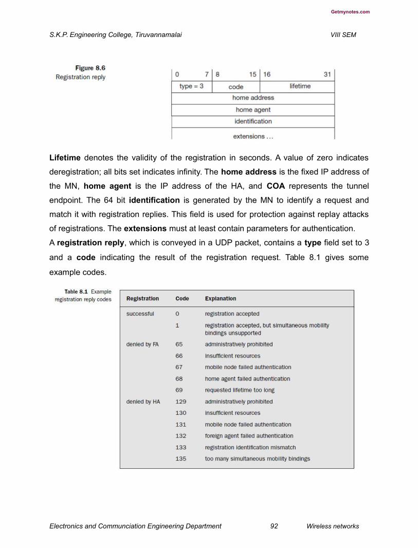
Getmynotes.com
S.K.P. Engineering College, Tiruvannamalai VIII SEM
Lifetime denotes the validity of the registration in seconds. A value of zero indicates
deregistration; all bits set indicates infinity. The home address is the fixed IP address of
the MN, home agent is the IP address of the HA, and COA represents the tunnel
endpoint. The 64 bit identification is generated by the MN to identify a request and
match it with registration replies. This field is used for protection against replay attacks
of registrations. The extensions must at least contain parameters for authentication.
A registration reply, which is conveyed in a UDP packet, contains a type field set to 3
and a code indicating the result of the registration request. Table 8.1 gives some
example codes.
Electronics and Communciation Engineering Department 92 Wireless networks
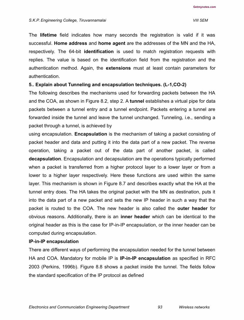
Getmynotes.com
S.K.P. Engineering College, Tiruvannamalai VIII SEM
The lifetime field indicates how many seconds the registration is valid if it was
successful. Home address and home agent are the addresses of the MN and the HA,
respectively. The 64-bit identification is used to match registration requests with
replies. The value is based on the identification field from the registration and the
authentication method. Again, the extensions must at least contain parameters for
authentication.
5.. Explain about Tunneling and encapsulation techniques. (L-1,CO-2)
The following describes the mechanisms used for forwarding packets between the HA
and the COA, as shown in Figure 8.2, step 2. A tunnel establishes a virtual pipe for data
packets between a tunnel entry and a tunnel endpoint. Packets entering a tunnel are
forwarded inside the tunnel and leave the tunnel unchanged. Tunneling, i.e., sending a
packet through a tunnel, is achieved by
using encapsulation. Encapsulation is the mechanism of taking a packet consisting of
packet header and data and putting it into the data part of a new packet. The reverse
operation, taking a packet out of the data part of another packet, is called
decapsulation. Encapsulation and decapsulation are the operations typically performed
when a packet is transferred from a higher protocol layer to a lower layer or from a
lower to a higher layer respectively. Here these functions are used within the same
layer. This mechanism is shown in Figure 8.7 and describes exactly what the HA at the
tunnel entry does. The HA takes the original packet with the MN as destination, puts it
into the data part of a new packet and sets the new IP header in such a way that the
packet is routed to the COA. The new header is also called the outer header for
obvious reasons. Additionally, there is an inner header which can be identical to the
original header as this is the case for IP-in-IP encapsulation, or the inner header can be
computed during encapsulation.
IP-in-IP encapsulation
There are different ways of performing the encapsulation needed for the tunnel between
HA and COA. Mandatory for mobile IP is IP-in-IP encapsulation as specified in RFC
2003 (Perkins, 1996b). Figure 8.8 shows a packet inside the tunnel. The fields follow
the standard specification of the IP protocol as defined
Electronics and Communciation Engineering Department 93 Wireless networks

Getmynotes.com
S.K.P. Engineering College, Tiruvannamalai VIII SEM
in RFC 791 (Postel, 1981) and the new interpretation of the former TOS, now DS field in
the context of differentiated services (RFC 2474, Nichols, 1998). The fields of the outer
header are set as follows. The version field ver is 4 for IP version 4, the internet header
length (IHL) denotes the length of the outer header in 32 bit words. DS(TOS) is just
copied from the inner header, the length field covers the complete encapsulated
packet. The fields up to TTL have no special meaning for mobile IP and are set
according to RFC 791. TTL must be high enough so the packet can reach the tunnel
endpoint. The next field, here
denoted with IP-in-IP, is the type of the protocol used in the IP payload. This field is set
to 4, the protocol type for IPv4 because again an IPv4 packet follows after this outer
header. IP checksum is calculated as usual. The next fields are the tunnel entry as
source address (the IP address of the HA) and the tunnel exit point as destination
address (the COA). If no options follow the outer header, the inner header starts with
Electronics and Communciation Engineering Department 94 Wireless networks
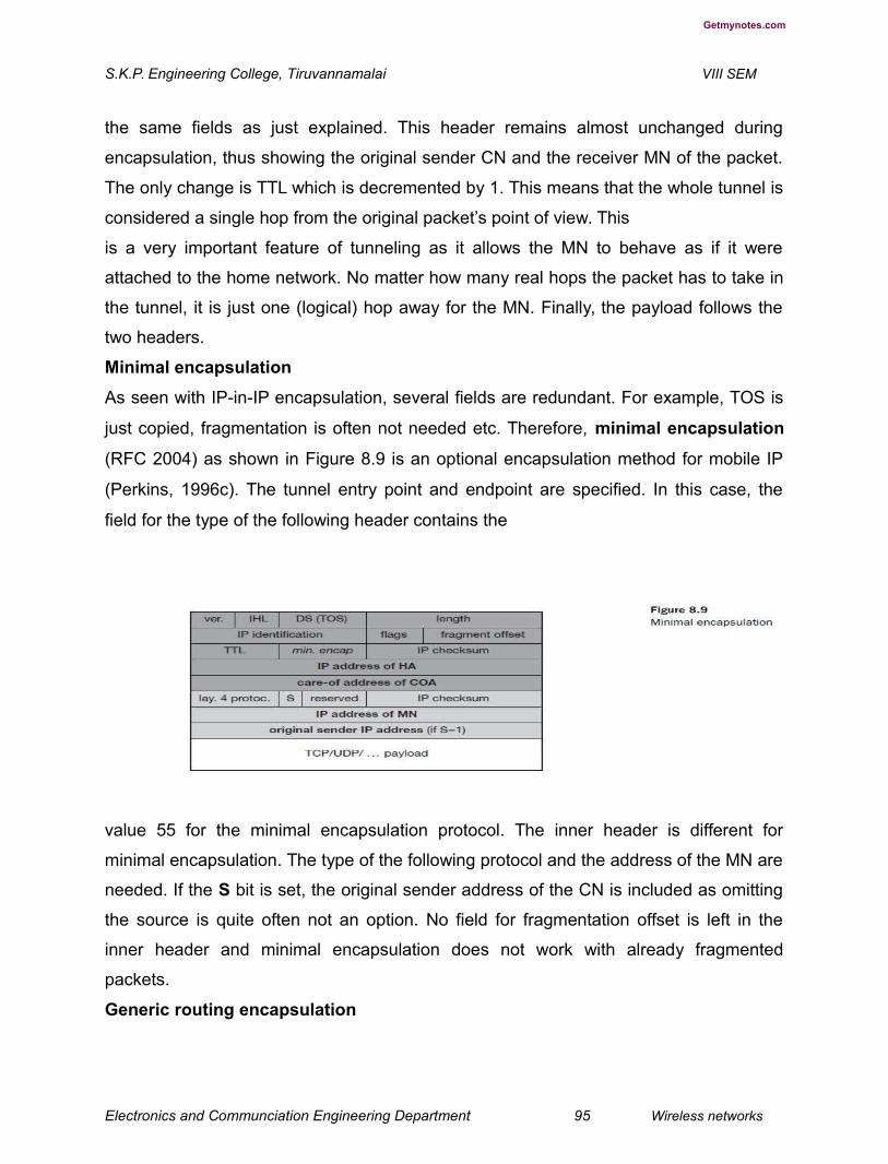
Getmynotes.com
S.K.P. Engineering College, Tiruvannamalai VIII SEM
the same fields as just explained. This header remains almost unchanged during
encapsulation, thus showing the original sender CN and the receiver MN of the packet.
The only change is TTL which is decremented by 1. This means that the whole tunnel is
considered a single hop from the original packet’s point of view. This
is a very important feature of tunneling as it allows the MN to behave as if it were
attached to the home network. No matter how many real hops the packet has to take in
the tunnel, it is just one (logical) hop away for the MN. Finally, the payload follows the
two headers.
Minimal encapsulation
As seen with IP-in-IP encapsulation, several fields are redundant. For example, TOS is
just copied, fragmentation is often not needed etc. Therefore, minimal encapsulation
(RFC 2004) as shown in Figure 8.9 is an optional encapsulation method for mobile IP
(Perkins, 1996c). The tunnel entry point and endpoint are specified. In this case, the
field for the type of the following header contains the
value 55 for the minimal encapsulation protocol. The inner header is different for
minimal encapsulation. The type of the following protocol and the address of the MN are
needed. If the S bit is set, the original sender address of the CN is included as omitting
the source is quite often not an option. No field for fragmentation offset is left in the
inner header and minimal encapsulation does not work with already fragmented
packets.
Generic routing encapsulation
Electronics and Communciation Engineering Department 95 Wireless networks

Getmynotes.com
S.K.P. Engineering College, Tiruvannamalai VIII SEM
While IP-in-IP encapsulation and minimal encapsulation work only for IP, the following
encapsulation scheme also supports other network layer protocols in addition to IP.
Generic routing encapsulation (GRE) allows the encapsulation of packets of one
protocol suite into the payload portion of a packet of another protocol suite (Hanks,
1994). Figure 8.10 shows this procedure. The packet of one protocol suite with the
original packet header and data is taken and a new GRE header is prepended. Together
this forms the new data part of the new packet. Finally, the header of the second
protocol suite is put in front. Figure 8.11 shows on the left side the fields of a packet
inside the tunnel between home agent and COA using GRE as an encapsulation
scheme according to RFC 1701. The outer header is the standard IP header with HA as
source address and COA as destination address. The protocol type used in this outer IP
Electronics and Communciation Engineering Department 96 Wireless networks

Getmynotes.com
S.K.P. Engineering College, Tiruvannamalai VIII SEM
header is 47 for GRE. The other fields of the outer packet, such as TTL and TOS, may
be copied from the original IP header. However, the TTL must be decremented by 1
when the packet is decapsulated to prevent indefinite forwarding. The GRE header
starts with several flags indicating if certain fields are present or not. A minimal GRE
header uses only 4 bytes; nevertheless, GRE is flexible enough to include several
mechanisms in its header. The C bit indicates if the checksum field is present and
contains valid information. If C is set, the checksum field contains a valid IP checksum
of the GRE header and the payload. The R bit indicates if the offset and routing fields
are present and contain valid information. The offset represents the offset in bytes for
the first source routing entry. The routing field, if present, has a variable length and
contains fields for source routing. If the C bit is set, the offset field is also present and,
vice versa, if the R bit is set, the checksum field must be present. The only reason for
this is to align the following fields to 4 bytes. The checksum field is valid only if C is set,
and the offset field is valid only if R is set respectively. GRE also offers a key field which
may be used for authentication. If this field is present, the K bit is set. However, the
authentication algorithms are not further specified by GRE. The sequence number bit S
Electronics and Communciation Engineering Department 97 Wireless networks

Getmynotes.com
S.K.P. Engineering College, Tiruvannamalai VIII SEM
indicates if the sequence number field is present, if the s bit is set, strict source routing
is used. Sequence
numbers may be used by a decapsulator to restore packet order. This can be important,
if a protocol guaranteeing in-order transmission is encapsulated and
transferred using a protocol which does not guarantee in-order delivery, e.g., IP. Now
the decapsulator at the tunnel exit must restore the sequence to maintain the
characteristic of the protocol. The recursion control field (rec.) is an important field that
additionally distinguishes
GRE from IP-in-IP and minimal encapsulation. This field represents a counter that
shows the number of allowed recursive encapsulations. As soon as a packet arrives at
an encapsulator it checks whether this field equals zero. If the field is not zero,
additional encapsulation is allowed – the packet is encapsulated and the field
decremented by one. Otherwise the packet will most likely be discarded. This
mechanism prevents indefinite recursive encasulation which
might happen with the other schemes if tunnels are set up improperly (e.g., several
tunnels forming a loop). The default value of this field should be 0, thus allowing only
one level of encapsulation. The following reserved fields must be zero and are ignored
on reception. The
version field contains 0 for the GRE version. The following 2 byte protocol field
represents the protocol of the packet following the GRE header. Several values have
been defined, e.g., 0 × 6558 for transparent Ethernet bridging using a GRE tunnel. In
the case of a mobile IP tunnel, the protocol field contains 0 × 800 for IP. The standard
header of the original packet follows with the source address of the correspondent node
and the destination address of the mobile node.
Figure 8.12 shows the simplified header of GRE following RFC 2784 (Farinacci, 2000),
which is a more generalized version of GRE compared to RFC 1701. This version does
Electronics and Communciation Engineering Department 98 Wireless networks

Getmynotes.com
S.K.P. Engineering College, Tiruvannamalai VIII SEM
not address mutual encapsulation and ignores several protocol-specific nuances on
purpose. The field C indicates again if a checksum is present. The next 5 bits are set to
zero, then 7 reserved bits follow. The version field contains the value zero. The
protocol type, again, defines the protocol of the payload following RFC 3232
(Reynolds, 2002). If the flag C is set, then checksum field and a field called reserved1
follows. The latter field is constant zero set to zero follow. RFC 2784 deprecates several
fields of RFC 1701, but can interoperate with RFC 1701-compliant implementations.
6.. Explain the Optimizations used the mobile IP Networks. (L-2,CO-2)
Imagine the following scenario. A Japanese and a German meet at a conference on
Hawaii. Both want to use their laptops for exchanging data, both run mobile IP for
mobility support. Now recall Figure 8.2 and think of the way the packets between both
computers take. If the Japanese sends a packet to the German, his computer sends the
data to the HA of the German, i.e., from Hawaii to Germany. The HA in Germany now
encapsulates the packets and tunnels them to the COA of the German laptop on
Hawaii. This means that although the computers might be only meters away, the
packets have to travel around the world! This inefficient behavior of a nonoptimized
mobile IP is called triangular routing. The triangle is made of the three segments, CN
to HA, HA to COA/MN, and MN back to CN. With the basic mobile IP protocol all
packets to the MN have to go through the HA. This can cause unnecessary overheads
for the network between CN and HA, but also between HA and COA, depending on the
current location of the
MN. As the example shows, latency can increase dramatically. This is particularly
unfortunate if the MNs and HAs are separated by, e.g., transatlantic links. One way to
optimize the route is to inform the CN of the current location of the MN. The CN can
learn the location by caching it in a binding cache which is a part of the local routing
table for the CN. The appropriate entity to
inform the CN of the location is the HA. The optimized mobile IP protocol needs four
additional messages.
Electronics and Communciation Engineering Department 99 Wireless networks
Getmynotes.com
S.K.P. Engineering College, Tiruvannamalai VIII SEM
● Binding request:
Any node that wants to know the current location of an MN can send a binding request
to the HA. The HA can check if the MN has allowed dissemination of its current location.
If the HA is allowed to reveal the location it sends back a binding update.
● Binding update:
This message sent by the HA to CNs reveals the current location of an MN. The
message contains the fixed IP address of the MN and the COA. The binding update can
request an acknowledgement.
● Binding acknowledgement:
If requested, a node returns this acknowledgement after receiving a binding update
message.
● Binding warning:
If a node decapsulates a packet for an MN, but it is not the current FA for this MN, this
node sends a binding warning. The warning contains MN’s home address and a target
node address, i.e., the address of the node that has tried to send the packet to this MN.
The recipient of the warning then knows that the target node could benefit from
obtaining a fresh
binding for the MN. The recipient can be the HA, so the HA should now send a binding
update to the node that obviously has a wrong COA for the MN.
Figure 8.13 explains these additional four messages together with the case of an MN
changing its FA. The CN can request the current location from the HA. If allowed by the
MN, the HA returns the COA of the MN via an update message. The CN acknowledges
this update message and stores the mobility binding. Now
the CN can send its data directly to the current foreign agent FAold. FAold forwards the
packets to the MN. This scenario shows a COA located at an FA. Encapsulation of data
for tunneling to the COA is now done by the CN, not the HA. The MN might now change
Electronics and Communciation Engineering Department 100 Wireless networks
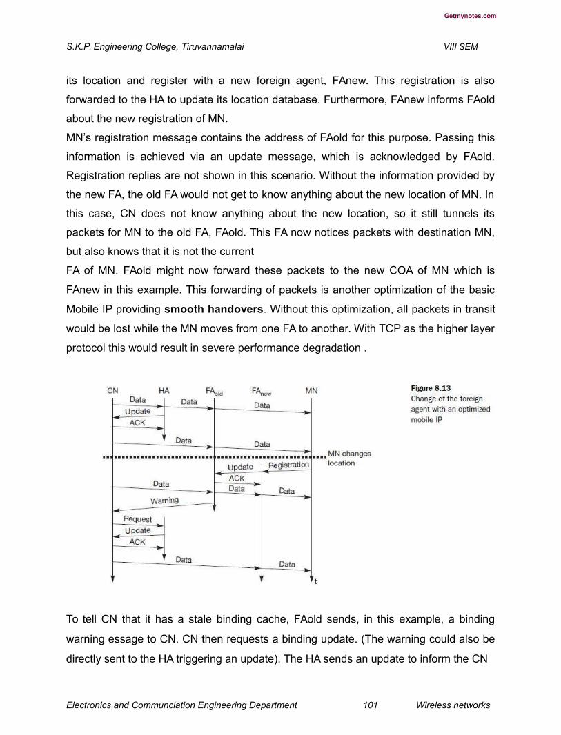
Getmynotes.com
S.K.P. Engineering College, Tiruvannamalai VIII SEM
its location and register with a new foreign agent, FAnew. This registration is also
forwarded to the HA to update its location database. Furthermore, FAnew informs FAold
about the new registration of MN.
MN’s registration message contains the address of FAold for this purpose. Passing this
information is achieved via an update message, which is acknowledged by FAold.
Registration replies are not shown in this scenario. Without the information provided by
the new FA, the old FA would not get to know anything about the new location of MN. In
this case, CN does not know anything about the new location, so it still tunnels its
packets for MN to the old FA, FAold. This FA now notices packets with destination MN,
but also knows that it is not the current
FA of MN. FAold might now forward these packets to the new COA of MN which is
FAnew in this example. This forwarding of packets is another optimization of the basic
Mobile IP providing smooth handovers. Without this optimization, all packets in transit
would be lost while the MN moves from one FA to another. With TCP as the higher layer
protocol this would result in severe performance degradation .
To tell CN that it has a stale binding cache, FAold sends, in this example, a binding
warning essage to CN. CN then requests a binding update. (The warning could also be
directly sent to the HA triggering an update). The HA sends an update to inform the CN
Electronics and Communciation Engineering Department 101 Wireless networks

Getmynotes.com
S.K.P. Engineering College, Tiruvannamalai VIII SEM
about the new location, which is acknowledged. Now CN can send its packets directly to
FAnew, again avoiding triangular routing. Unfortunately, this optimization of mobile IP to
avoid triangular routing
causes several security problems (e.g., tunnel hijacking) as discussed in Montenegro
(1998). Not all users of mobile communication systems want to reveal their current
‘location’ (in the sense of an IP subnet) to a communication partner.
7..Explain the Reverse tunneling techniques used in WLAN.. (L-1,CO-2)
At first glance, the return path from the MN to the CN shown in Figure 8.2 looks quite
simple. The MN can directly send its packets to the CN as in any other standard IP
situation. The destination address in the packets is that of CN. But there are several
severe problems associated with this simple solution.
● Firewalls:
Almost all companies and many other institutions secure their internal networks
(intranet) connected to the internet with the help of a firewall. All data to and from the
intranet must pass through the firewall. Besides many other functions, firewalls can be
set up to filter out malicious
addresses from an administrator’s point of view. Quite often firewalls only allow packets
with topologically correct addresses to pass. This provides at least a first and simple
protection against misconfigured systems of unknown addresses. However, MN still
sends packets with its fixed IP address as source which is not topologically correct in a
foreign network. Firewalls often filter packets coming from outside containing a source
address from computers of the internal network. This avoids other computers that could
use internal addresses and claim to be internal computers. However, this also implies
that an MN cannot send a packet to a computer residing in its home network.
Altogether, this means that not only does the destination address matter for forwarding
IP packets, but also the source address due to security concerns. Further omplications
arise through the use of private addresses inside the intranet and the translation into
global addresses when communicating with the internet. This network address
Electronics and Communciation Engineering Department 102 Wireless networks

Getmynotes.com
S.K.P. Engineering College, Tiruvannamalai VIII SEM
translation (NAT, network address translator, RFC 3022, Srisuresh, 2001) is used by
many companies to
hide internal resources (routers, computers, printers etc.) and to use only some globally
available addresses (Levkowetz, 2002, tries to solve the problems arising when using
NAT together with mobile IP).
● Multi-cast:
Reverse tunnels are needed for the MN to participate in a multicast group. While the
nodes in the home network might participate in a multi-cast group, an MN in a foreign
network cannot transmit multi-cast packets in a way that they emanate from its home
network without a reverse tunnel. The foreign network might not even provide the
technical infrastructure for multi-cast communication (multi-cast backbone, Mbone).
● TTL:
Consider an MN sending packets with a certain TTL while still in its home network. The
TTL might be low enough so that no packet is transmitted outside a certain region. If the
MN now moves to a foreign network, this TTL might be too low for the packets to reach
the same nodes as before. Mobile IP is no longer transparent if a user has to adjust the
TTL while moving. A reverse tunnel is needed that represents only one hop, no matter
how many hops are really needed from the foreign to the home network. All these
considerations led to RFC 2344 (Montenegro, 1998) defining reverse tunneling as an
extension to mobile IP. The new RFC 3024 (Montenegro, 2001) renders RFC 2344
obsolete but comprises only some minor changes for
the original standard. The RFC was designed backwards-compatible to mobile IP and
defines topologically correct reverse tunneling as necessary to handle the problems
described above. Reverse tunneling was added as an option to mobile IP in the new
standard (RFC 3344).
Obviously, reverse tunneling now creates a triangular routing problem in the reverse
direction. All packets from an MN to a CN go through the HA. RFC 3024 does not offer
a solution for this reverse triangular routing, because it is not clear if the CN can
Electronics and Communciation Engineering Department 103 Wireless networks
Getmynotes.com
S.K.P. Engineering College, Tiruvannamalai VIII SEM
decapsulate packets. Remember that mobile IP should work together with all traditional,
non-mobile IP nodes. Therefore, one cannot assume that a CN is able to be a tunnel
endpoint. Reverse tunneling also raises several security issues which have not been
really solved up to now. For example, tunnels starting in the private network of a
company and reaching out into the internet could be hijacked and abused for
sending packets through a firewall. It is not clear if companies would allow for setting up
tunnels through a firewall without further checking of packets. It is more likely that a
company will set up a special virtual network for visiting mobile nodes outside the
firewall with full connectivity to the internet. This allows guests to use their mobile
equipment, and at the same time, today’s security standards are maintained. Initial
architectures integrating mobility and security aspects within firewalls exist (Mink, 2000a
and b).
8.Explain in detail about IPv6. (L-1,CO-2)
While mobile IP was originally designed for IP version 4, IP version 6 (Deering, 1998)
makes life much easier. Several mechanisms that had to be specified separately for
mobility support come free in IPv6 (Perkins, 1996d), (Johnson, 2002b). One issue is
security with regard to authentication, which is now a required feature for all IPv6 nodes.
No special mechanisms as add-ons are needed for securing mobile IP registration.
Every IPv6 node masters address autoconfiguration – the mechanisms for acquiring a
COA are already built in. Neighbor
discovery as a mechanism mandatory for every node is also included in the
specification; special foreign agents are no longer needed to advertise services.
Combining the features of autoconfiguration and neighbor discovery means that every
mobile node is able to create or obtain a topologically correct address for the current
point of attachment.
Every IPv6 node can send binding updates to another node, so the MN can send its
current COA directly to the CN and HA. These mechanisms are an integral part of IPv6.
Electronics and Communciation Engineering Department 104 Wireless networks

Getmynotes.com
S.K.P. Engineering College, Tiruvannamalai VIII SEM
A soft handover is possible with IPv6. The MN sends its new COA to the old router
servicing the MN at the old COA, and the old router encapsulates all incoming packets
for the MN and forwards them to the new COA.
Altogether, mobile IP in IPv6 networks requires very few additional mechanisms of a
CN, MN, and HA. The FA is not needed any more. A CN only has to be able to process
binding updates, i.e., to create or to update an entry in the routing cache. The MN itself
has to be able to decapsulate packets, to detect when it needs a new COA, and to
determine when to send binding updates to the HA and CN. A HA must be able to
encapsulate packets. However, IPv6 does
not solve any firewall or privacy problems. Additional mechanisms on higher layers are
needed for this.
IP micro-mobility support
Mobile IP exhibits several problems regarding the duration of handover and the
scalability of the registration procedure. Assuming a large number of mobile devices
changing networks quite frequently, a high load on the home agents as well as on the
networks is generated by registration and binding update messages. IP micro-mobility
protocols can complement mobile IP by offering fast and almost seamless handover
control in limited geographical areas.
Consider a client arriving with his or her laptop at the customer’s premises. The home
agent only has to know an entry point to the customer’s network, not the details within
this network. The entry point acts as the current location. Changes in the location within
the customer’s network should be handled locally to minimize network traffic and to
speed-up local handover. The basic
underlying idea is the same for all micro-mobility protocols: Keep the frequent updates
generated by local changes of the points of attachment away from the home network
and only inform the home agent about major changes, i.e., changes of a region. In
some sense all micro-mobility protocols establish a hierarchy. However, the debate is
still going on if micro-mobility apects should really be handled on the IP layer or if layer
2 is the better place for it. Layer 2 mobility support would comprise, e.g., the inter
access point protocol (IAPP) of 802.11 WLANs or the mobility support mechanisms of
mobile phone systems. The following presents three of the most prominent approaches,
Electronics and Communciation Engineering Department 105 Wireless networks

Getmynotes.com
S.K.P. Engineering College, Tiruvannamalai VIII SEM
which should be seen neither as standards nor as final solutions of the micro-mobility
problems. Campbell (2002) presents a comparison of the three approaches.
Cellular IP
Cellular IP (Valko, 1999), (Campbell, 2000) provides local handovers without renewed
registration by instaling a single cellular IP gateway (CIPGW) for each domain, which
acts to the outside world as a foreign agent (see Figure 8.14). Inside the cellular IP
domain, all nodes collect routing information for accessing MNs based on the origin of
packets sent by the MNs towards the CIPGW. Soft handovers are achieved by allowing
simultaneous forwarding of packets destined for a mobile node along multiple paths. A
mobile node moving between adjacent cells will temporarily be able to receive packets
via both old and new base stations (BS) if this is supported by the lower protocol
layers.
Concerning the manageability of cellular IP, it has to be noted that the approach has a
simple and elegant architecture and is mostly self-configuring. However, mobile IP
tunnels could be controlled more easily if the CIPGW was integrated into a firewall, but
there are no detailed specifications in (Campbell, 2000) regarding such integration.
Cellular IP requires changes to the basic mobile IP protocol and is not transparent to
existing systems. The foreign network’s
routing tables are changed based on messages sent by mobile nodes. These should
not be trusted blindly even if they have been authenticated. This could be exploited by
systems in the foreign network for wiretapping packets
Electronics and Communciation Engineering Department 106 Wireless networks

Getmynotes.com
S.K.P. Engineering College, Tiruvannamalai VIII SEM
destined for an MN by sending packets to the CIPGW with the source address set to the
MN’s address. In enterprise scenarios requiring basic communications security, this may
not be acceptable.
Advantage
● Manageability: Cellular IP is mostly self-configuring, and integration of the
CIPGW into a firewall would facilitate administration of mobility-related
functionality. This is, however, not explicitly specified in (Campbell, 2000).
Disadvantages
● Efficiency: Additional network load is induced by forwarding packets on multiple paths.
● Transparency: Changes to MNs are required.
● Security: Routing tables are changed based on messages sent by mobile nodes.
Additionally, all systems in the network can easily obtain a copy of all packets
destined for an MN by sending packets with the MN’s source address to the
CIPGW.
9..Brief about Hawaii and its evolution technqiues. (L-1,CO-2)
HAWAII (Handoff-Aware Wireless Access Internet Infrastructure, Ramjee, 1999) tries to
keep micro-mobility support as transparent as possible for both home agents and
mobile nodes (which have to support route optimization). Its concrete goals are
performance and reliability improvements and support for quality of service
mechanisms. On entering an HAWAII domain, a mobile node obtains a co-located COA
(see Figure 8.15, step 1) and registers with the HA
(step 2). Additionally, when moving to another cell inside the foreign domain, the MN
sends a registration request to the new base station as to a foreign agent
Electronics and Communciation Engineering Department 107 Wireless networks

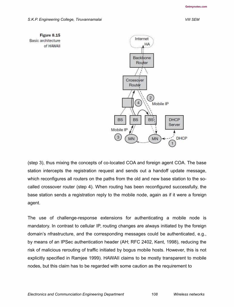
Getmynotes.com
S.K.P. Engineering College, Tiruvannamalai VIII SEM
(step 3), thus mixing the concepts of co-located COA and foreign agent COA. The base
station intercepts the registration request and sends out a handoff update message,
which reconfigures all routers on the paths from the old and new base station to the so-
called crossover router (step 4). When routing has been reconfigured successfully, the
base station sends a registration reply to the mobile node, again as if it were a foreign
agent.
The use of challenge-response extensions for authenticating a mobile node is
mandatory. In contrast to cellular IP, routing changes are always initiated by the foreign
domain’s nfrastructure, and the corresponding messages could be authenticated, e.g.,
by means of an IPSec authentication header (AH; RFC 2402, Kent, 1998), reducing the
risk of malicious rerouting of traffic initiated by bogus mobile hosts. However, this is not
explicitly specified in Ramjee 1999). HAWAII claims to be mostly transparent to mobile
nodes, but this claim has to be regarded with some caution as the requirement to
Electronics and Communciation Engineering Department 108 Wireless networks
Getmynotes.com
S.K.P. Engineering College, Tiruvannamalai VIII SEM
support a co-located care-ofaddress as well as to interact with foreign agents could
cause difficulties with some mobile nodes.
Advantages
● Security: Challenge-response extensions are mandatory. In contrast to Cellular
IP, routing changes are always initiated by the foreign domain’s infrastructure.
● Transparency: HAWAII is mostly transparent to mobile nodes.
Disadvantages
● Security: There are no provisions regarding the setup of IPSec tunnels.
● Implementation: No private address support is possible because of collocated COAs.
10.Explain the advantages of Hierarchical mobile IPv6 (HMIPv6). (L-1,CO-2)
As introducing hierarchies is the natural choice for handling micro-mobility issues,
several proposals for a ‘hierarchical’ mobile IP exist. What follows is based on Soliman,
(2002). MIPv6 provides micro-mobility support by installing a mobility anchor point
(MAP), which is responsible for a certain domain and acts as a local HA within this
domain for visiting MNs (see Figure 8.16). The MAP receives all packets on behalf of
the MN, encapsulates and forwards them directly to the MN’s current address (link
COA, LCOA). As long as an MN stays within the domain of a MAP, the globally visible
COA (regional COA, RCOA) does not change. A MAP domain’s boundaries are defined
by the access routers (AR) advertising the MAP information to the attached MNs. A
MAP assists with local handovers and maps RCOA to LCOA. MNs register their RCOA
with the HA using a binding update. When a MN moves locally it must only register its
new LCOA with its MAP. The RCOA stays unchanged. To support smooth handovers
Electronics and Communciation Engineering Department 109 Wireless networks
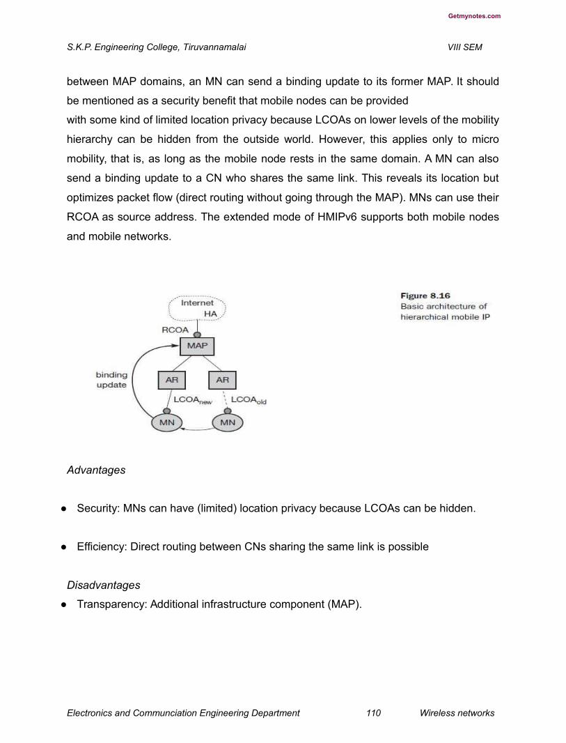
Getmynotes.com
S.K.P. Engineering College, Tiruvannamalai VIII SEM
between MAP domains, an MN can send a binding update to its former MAP. It should
be mentioned as a security benefit that mobile nodes can be provided
with some kind of limited location privacy because LCOAs on lower levels of the mobility
hierarchy can be hidden from the outside world. However, this applies only to micro
mobility, that is, as long as the mobile node rests in the same domain. A MN can also
send a binding update to a CN who shares the same link. This reveals its location but
optimizes packet flow (direct routing without going through the MAP). MNs can use their
RCOA as source address. The extended mode of HMIPv6 supports both mobile nodes
and mobile networks.
Advantages
● Security: MNs can have (limited) location privacy because LCOAs can be hidden.
● Efficiency: Direct routing between CNs sharing the same link is possible
Disadvantages
● Transparency: Additional infrastructure component (MAP).
Electronics and Communciation Engineering Department 110 Wireless networks
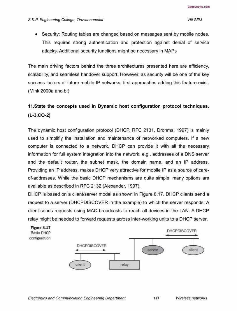
Getmynotes.com
S.K.P. Engineering College, Tiruvannamalai VIII SEM
● Security: Routing tables are changed based on messages sent by mobile nodes.
This requires strong authentication and protection against denial of service
attacks. Additional security functions might be necessary in MAPs
The main driving factors behind the three architectures presented here are efficiency,
scalability, and seamless handover support. However, as security will be one of the key
success factors of future mobile IP networks, first approaches adding this feature exist.
(Mink 2000a and b.)
11.State the concepts used in Dynamic host configuration protocol techniques.
(L-3,CO-2)
The dynamic host configuration protocol (DHCP, RFC 2131, Drohms, 1997) is mainly
used to simplifiy the installation and maintenance of networked computers. If a new
computer is connected to a network, DHCP can provide it with all the necessary
information for full system integration into the network, e.g., addresses of a DNS server
and the default router, the subnet mask, the domain name, and an IP address.
Providing an IP address, makes DHCP very attractive for mobile IP as a source of care-
of-addresses. While the basic DHCP mechanisms are quite simple, many options are
available as described in RFC 2132 (Alexander, 1997).
DHCP is based on a client/server model as shown in Figure 8.17. DHCP clients send a
request to a server (DHCPDISCOVER in the example) to which the server responds. A
client sends requests using MAC broadcasts to reach all devices in the LAN. A DHCP
relay might be needed to forward requests across inter-working units to a DHCP server.
Electronics and Communciation Engineering Department 111 Wireless networks
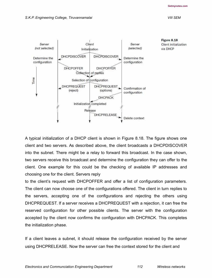
Getmynotes.com
S.K.P. Engineering College, Tiruvannamalai VIII SEM
A typical initialization of a DHCP client is shown in Figure 8.18. The figure shows one
client and two servers. As described above, the client broadcasts a DHCPDISCOVER
into the subnet. There might be a relay to forward this broadcast. In the case shown,
two servers receive this broadcast and determine the configuration they can offer to the
client. One example for this could be the checking of available IP addresses and
choosing one for the client. Servers reply
to the client’s request with DHCPOFFER and offer a list of configuration parameters.
The client can now choose one of the configurations offered. The client in turn replies to
the servers, accepting one of the configurations and rejecting the others using
DHCPREQUEST. If a server receives a DHCPREQUEST with a rejection, it can free the
reserved configuration for other possible clients. The server with the configuration
accepted by the client now confirms the configuration with DHCPACK. This completes
the initialization phase.
If a client leaves a subnet, it should release the configuration received by the server
using DHCPRELEASE. Now the server can free the context stored for the client and
Electronics and Communciation Engineering Department 112 Wireless networks

Getmynotes.com
S.K.P. Engineering College, Tiruvannamalai VIII SEM
offer the configuration again. The configuration a client gets from a server is only leased
for a certain amount of time, it has to be reconfirmed from time to time. Otherwise the
server will free the configuration. This timeout of configuration helps in the case of
crashed nodes or nodes moved away without releasing the context.
DHCP is a good candidate for supporting the acquisition of care-ofaddresses for mobile
nodes. The same holds for all other parameters needed, such as addresses of the
default router, DNS servers, the timeserver etc. A DHCP server should be located in the
subnet of the access point of the mobile node, or at least a DHCP relay should provide
forwarding of the messages. RFC 3118
(Drohms, 2001) specifies authentication for DHCP messages which is needed to protect
mobile nodes from malicious DHCP servers. Without authentication, the mobile node
cannot trust a DHCP server, and the DHCP server cannot trust the mobile node.
Mobile ad-hoc networks
Mobility support described in sections 8.1 and 8.2 relies on the existence of at least
some infrastructure. Mobile IP requires, e.g., a home agent, tunnels, and default
routers. DHCP requires servers and broadcast capabilities of the medium reaching all
participants or relays to servers. Cellular phone networks require base stations,
infrastructure networks etc. However, there may be several situations where users of a
network cannot rely on an infrastructure, it is too expensive, or there is none at all. In
these situations mobile ad-hoc networks are the only choice. It is important to note that
this section focuses on so-called multi-hop ad-hoc networks when describing adhoc
networking. The ad-hoc setting up of a connection with an infrastructure is not the main
issue here. These networks should be mobile and use wireless communications.
Examples for the use of such mobile, wireless, multi-hop ad-hoc networks, which are
only called ad-hoc networks here for simplicity, are:
● Instant infrastructure:
Electronics and Communciation Engineering Department 113 Wireless networks

Getmynotes.com
S.K.P. Engineering College, Tiruvannamalai VIII SEM
Unplanned meetings, spontaneous interpersonal communications etc. cannot rely on
any infrastructure. Infrastructures need planning and administration. It would take too
long to set up this kind of infrastructure; therefore, ad-hoc connectivity has to be set up.
● Disaster relief:
Infrastructures typically break down in disaster areas. Hurricanes cut phone and power
lines, floods destroy base stations, fires burn servers. Emergency teams can only rely
on an infrastructure they can set up themselves. No forward planning can be done, and
the set-up must
be extremely fast and reliable. The same applies to many military activities, which is, to
be honest, one of the major driving forces behind mobile ad-hoc networking research.
● Remote areas:
Even if infrastructures could be planned ahead, it is sometimes too expensive to set up
an infrastructure in sparsely populated areas. Depending on the communication pattern,
ad-hoc networks or satellite infrastructures can be a solution.
● Effectiveness:
Services provided by existing infrastructures might be too expensive for certain
applications. If, for example, only connectionoriented cellular networks exist, but an
application sends only a small status information every other minute, a cheaper ad-hoc
packet-oriented network might be a better solution. Registration procedures might take
too long, and communication overheads might be too high with existing networks.
Application-tailored ad-hoc networks can offer a better solution.
Electronics and Communciation Engineering Department 114 Wireless networks
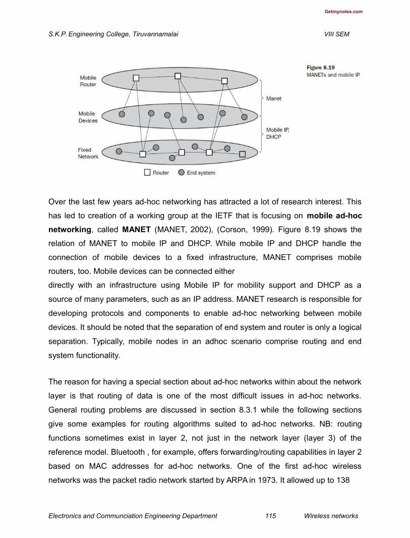
Getmynotes.com
S.K.P. Engineering College, Tiruvannamalai VIII SEM
Over the last few years ad-hoc networking has attracted a lot of research interest. This
has led to creation of a working group at the IETF that is focusing on mobile ad-hoc
networking, called MANET (MANET, 2002), (Corson, 1999). Figure 8.19 shows the
relation of MANET to mobile IP and DHCP. While mobile IP and DHCP handle the
connection of mobile devices to a fixed infrastructure, MANET comprises mobile
routers, too. Mobile devices can be connected either
directly with an infrastructure using Mobile IP for mobility support and DHCP as a
source of many parameters, such as an IP address. MANET research is responsible for
developing protocols and components to enable ad-hoc networking between mobile
devices. It should be noted that the separation of end system and router is only a logical
separation. Typically, mobile nodes in an adhoc scenario comprise routing and end
system functionality.
The reason for having a special section about ad-hoc networks within about the network
layer is that routing of data is one of the most difficult issues in ad-hoc networks.
General routing problems are discussed in section 8.3.1 while the following sections
give some examples for routing algorithms suited to ad-hoc networks. NB: routing
functions sometimes exist in layer 2, not just in the network layer (layer 3) of the
reference model. Bluetooth , for example, offers forwarding/routing capabilities in layer 2
based on MAC addresses for ad-hoc networks. One of the first ad-hoc wireless
networks was the packet radio network started by ARPA in 1973. It allowed up to 138
Electronics and Communciation Engineering Department 115 Wireless networks

Getmynotes.com
S.K.P. Engineering College, Tiruvannamalai VIII SEM
nodes in the ad-hoc network and used IP packets for data transport. This made an easy
connection possible to the ARPAnet, the starting point of today’s Internet. Twenty radio
channels between 1718.4–1840 MHz were used offering 100 or 400 kbit/s. The system
used DSSS with 128 or 32 chips/bit. A variant of distance vector routing was used in this
ad-hoc network (Perlman, 1992). In this approach, each node sends a routing
advertisement every 7.5 s. These advertisements contain a neighbor table with a list of
link qualities to each neighbor. Each node updates the local routing table according to
the distance vector algorithm based on these advertisements. Received packets also
help to update the routing table. A sender now transmits a packet to its first hop
neighbor using the local neighbor table. Each node forwards a packet received based
on its own local neighbor table. Several enhancements to this simple scheme are
needed to avoid routing loops and to reflect the possibly fast changing topology. The
following sections discuss routing problems and enhanced routing mechanisms for ad-
hoc networks in more detail. Perkins (2001a) comprises a collection of many routing
protocols together with some initial performance considerations.
Routing
While in wireless networks with infrastructure support a base station always reaches all
mobile nodes, this is not always the case in an ad-hoc network. A destination node
might be out of range of a source node transmitting packets. Routing is needed to find a
path between source and destination and to forward the packets appropriately. In
wireless networks using an infrastructure, cells have been defined. Within a cell, the
base station can reach all mobile nodes
without routing via a broadcast. In the case of ad-hoc networks, each node must be able
to forward data for other nodes. This creates many additional problems that are
discussed in the following paragraphs. Figure 8.20 gives a simple example of an ad-hoc
network. At a certain time t1 the network topology might look as illustrated on the left
side of the figure. Five nodes, N1 to N5, are connected depending on the current
transmission characteristics between them. In this snapshot of the network, N4 can
receive N1 over a good link, but N1 receives N4 only via a weak link. Links do not
Electronics and Communciation Engineering Department 116 Wireless networks

Getmynotes.com
S.K.P. Engineering College, Tiruvannamalai VIII SEM
necessarily have the same characteristics in both directions. The reasons for this are,
e.g., different antenna characteristics or transmit power. N1 cannot receive N2 at all, N2
receives a signal from N1.
This situation can change quite fast as the snapshot at t2 shows. N1 cannot receive N4
any longer, N4 receives N1 only via a weak link. But now N1 has an asymmetric but bi-
directional link to N2 that did not exist before. This very simple example already shows
some fundamental differences between wired networks and ad-hoc wireless networks
related to routing.
● Asymmetric links:
Node A receives a signal from node B. But this does not tell us anything about the
quality of the connection in reverse. B might receive nothing, have a weak link, or even
have a better link than the reverse direction. Routing information collected for one
direction is of almost no use for the other direction. However, many routing algorithms
for wired networks rely on a symmetric scenario.
● Redundant links:
Wired networks, too, have redundant links to survive link failures. However, there is only
some redundancy in wired networks, which, additionally, are controlled by a network
administrator. In ad-hoc networks nobody controls redundancy, so there might be many
redundant links up to
Electronics and Communciation Engineering Department 117 Wireless networks

Getmynotes.com
S.K.P. Engineering College, Tiruvannamalai VIII SEM
the extreme of a completely meshed topology. Routing algorithms for wired networks
can handle some redundancy, but a high redundancy can cause a large computational
overhead for routing table updates.
● Interference:
In wired networks links exist only where a wire exists, and connections are planned by
network administrators. This is not the case for wireless ad-hoc networks. Links come
and go depending on transmission characteristics, one transmission might interfere with
another, and nodes might overhear the transmissions of other nodes. Interference
creates new problems by ‘unplanned’ links between nodes: if two close-by nodes
forward two transmissions, they might interfere and destroy each other. On the other
hand, interference might also help routing. A node can learn the topology with the help
of packets it has overheard.
● Dynamic topology:
The greatest problem for routing arises from the highly dynamic topology. The mobile
nodes might move as shown in Figure 8.20 or medium characteristics might change.
This results in frequent changes in topology, so snapshots are valid only for a very short
period of time. In adhoc networks, routing tables must somehow reflect these frequent
changes in topology, and routing algorithms have to be adapted. Routing algorithms
used in wired networks would either react much too slowly or generate too many
updates to reflect all changes in topology. Routing table updates in fixed networks, for
example, take place every 30 seconds. This updating frequency might be too low to be
useful for ad-hoc networks. Some algorithms rely on a complete picture of the whole
network. While this works in wired networks where changes are rare, it fails completely
in ad-hoc networks. The topology changes during the distribution of the ‘current’
snapshot of the network, rendering the snapshot useless.
Let us go back to the example network in Figure 8.20 and assume that node N1 wants
to send data to N3 and needs an acknowledgement. If N1 had a complete overview of
the network at time t1, which is not always the case in ad-hoc networks, it would choose
the path N1, N2, N3, for this requires only two hops (if we use hops as metric).
Electronics and Communciation Engineering Department 118 Wireless networks

Getmynotes.com
S.K.P. Engineering College, Tiruvannamalai VIII SEM
Acknowledgements cannot take the same path, N3 chooses N3, N5, N4, N1. This takes
three hops and already shows that routing
also strongly influences the function of higher layers. TCP, for example, makes round
trip measurements assuming the same path in both directions. This is obviously wrong
in the example shown, leading to misinterpretations of measurements and inefficiencies
.
Just a moment later, at time t2, the topology has changed. Now N3 cannot take the
same path to send acknowledgements back to N1, while N1 can still take the old path to
N3. Although already more complicated than fixed networks, this example still assumes
that nodes can have a complete insight into the current situation. The optimal
knowledge for every node would be a description of the current connectivity between all
nodes, the expected traffic flows, capacities of all links, delay of each link, and the
computing and battery power of each node. While even in fixed networks traffic flows
are not exactly predictable, for ad-hoc networks link capacities are additionally
unknown. The capacity of each link can change from 0 to the maximum of the
transmission technology used. In real ad-hoc networks no node knows all these factors,
and establishing up-to-date snapshots of the network is almost impossible. Ad-hoc
networks using mobile nodes face additional problems due to hardware limitations.
Using the standard routing protocols with periodic updates wastes battery power without
sending any user data and disables sleep modes. Periodic updates waste bandwidth
and these resources are already scarce for wireless links.
An additional problem is interference between two or more transmissions that do not
use the same nodes for forwarding. If, for example, a second transmission from node
N4 to N5 (see Figure 8.20) takes place at the same time as the transmission from N1 to
N3, they could interfere. Interference could take place at N2 which can receive signals
from N1 and N4, or at N5 receiving N4 and N2. If shielded correctly, there is no
interference between two wires.
Considering all the additional difficulties in comparison to wired networks, the following
observations concerning routing can be made for ad-hoc networks with moving nodes.
● Traditional routing algorithms known from wired networks will not work efficiently
(e.g., distance vector algorithms such as RIP (Hendrik, 1988), (Malkin, 1998)
converge much
Electronics and Communciation Engineering Department 119 Wireless networks


Getmynotes.com
S.K.P. Engineering College, Tiruvannamalai VIII SEM
too slowly) or fail completely (e.g., link state algorithms such as OSPF (Moy, 1998)
exchange complete pictures of the network). These algorithms have not been designed
with a highly dynamic topology, asymmetric links, or interference in mind.
● Routing in wireless ad-hoc networks cannot rely on layer three knowledge alone.
Information from lower layers concerning connectivity or interference can help
routing algorithms to find a good path.
● Centralized approaches will not really work, because it takes too long to collect
the current status and disseminate it again. Within this time the topology has
already changed.
● Many nodes need routing capabilities. While there might be some without, at
least one router has to be within the range of each node. Algorithms have to
consider the limited battery power of these nodes.
● The notion of a connection with certain characteristics cannot work properly. Ad-
hoc networks will be connectionless, because it is not possible to maintain a
connection in a fast changing environment and to forward data following this
connection. Nodes have to make local decisions for forwarding and send packets
roughly toward the final destination.
● A last alternative to forward a packet across an unknown topology is flooding.
This approach always works if the load is low, but it is very inefficient. A hop
counter is needed in each packet to avoid looping, and the diameter of the ad-
hoc network, i.e., the maximum number of hops, should be known. (The number
of nodes can be used as an upper bound.)
Hierarchical clustering of nodes might help. If it is possible to identify certain groups of
nodes belonging together, clusters can be established. While individual nodes might
move faster, the whole cluster can be rather stationary. Routing between clusters might
be simpler and less dynamic (see section 8.3.5.2). The following sections give two
Electronics and Communciation Engineering Department 120 Wireless networks

Getmynotes.com
S.K.P. Engineering College, Tiruvannamalai VIII SEM
examples for routing algorithms that were historically at the beginning of MANET
research, DSDV and DSR, and useful metrics that are different from the usual hop
counting. An overview of protocols follows. This is subdivided into the three categories:
flat, hierarchical, and geographic-position-assisted routing based on Hong (2002).
12.How the Destination sequence distance vector used in the efficiency of the
WLANs? (L-1,CO-2)
Destination sequence distance vector (DSDV) routing is an enhancement to distance
vector routing for ad-hoc networks (Perkins, 1994). DSDV can be considered
historically, however, an on-demand version (ad-hoc on-demand distance vector,
AODV) is among the protocols currently discussed (see section 8.3.5). Distance vector
routing is used as routing information protocol (RIP) in wired networks. It performs
extremely poorly with certain network changes due to the count-to-infinity problem.
Each node exchanges its neighbor table periodically with its neighbors. Changes at one
node in the network propagate slowly through the network (step-by-step with every
exchange). The strategies to avoid this problem which are used in fixed networks
(poisoned-reverse/splithorizon (Perlman, 1992)) do not help in the case of wireless ad-
hoc networks, due to the rapidly changing topology. This might create loops or
unreachable regions within the network.
DSDV now adds two things to the distance vector algorithm:
● Sequence numbers:
Each routing advertisement comes with a sequence number. Within ad-hoc networks,
advertisements may propagate along many paths. Sequence numbers help to apply the
advertisements in correct order. This avoids the loops that are likely with the unchanged
distance vector algorithm.
Electronics and Communciation Engineering Department 121 Wireless networks

Getmynotes.com
S.K.P. Engineering College, Tiruvannamalai VIII SEM
● Damping:
Transient changes in topology that are of short duration should not destabilize the
routing mechanisms. Advertisements containing changes in the topology currently
stored are therefore not disseminated further. A node waits with dissemination if these
changes are probably unstable. Waiting time depends on the time between the first and
the best announcement of a path to a certain destination.
The routing table for N1 in Figure 8.20 would be as shown in Table 8.2. For each node
N1 stores the next hop toward this node, the metric (here number of hops), the
sequence number of the last advertisement for this node, and the time at which the path
has been installed first. The table contains flags and a settling time helping to decide
when the path can be assumed stable. Router advertisements from N1 now contain
data from the first, third, and fourth column: destination address, metric, and sequence
number. Besides being loop-free at all times, DSDV has low memory requirements and
a quick convergence via triggered updates.
Dynamic source routing
Imagine what happens in an ad-hoc network where nodes exchange packets from time
to time, i.e., the network is only lightly loaded, and DSDV or one of the traditional
distance vector or link state algorithms is used for updating routing tables. Although only
some user data has to be transmitted, the nodes exchange routing information to keep
track of the topology. These algorithms maintain routes between all nodes, although
there may currently be no data exchange at all. This causes unnecessary traffic and
prevents nodes from saving battery power.
Electronics and Communciation Engineering Department 122 Wireless networks

Getmynotes.com
S.K.P. Engineering College, Tiruvannamalai VIII SEM
Dynamic source routing (DSR), therefore, divides the task of routing into two separate
problems (Johnson, 1996), (Johnson, 2002a):
● Route discovery: A node only tries to discover a route to a destination if it has to
send something to this destination and there is currently no known route.
● Route maintenance: If a node is continuously sending packets via a route, it has
to make sure that the route is held upright. As soon as a node detects problems
with the current route, it has to find an alternative.
The basic principle of source routing is also used in fixed networks, e.g. token rings.
Dynamic source routing eliminates all periodic routing updates and works as follows. If a
node needs to discover a route, it broadcasts a route request with a unique identifier
and the destination address as parameters. Any node that receives a route request
does the following.
● If the node has already received the request (which is identified using the unique
identifier), it drops the request packet.
● If the node recognizes its own address as the destination, the request has
reached its target.
Electronics and Communciation Engineering Department 123 Wireless networks

Getmynotes.com
S.K.P. Engineering College, Tiruvannamalai VIII SEM
● Otherwise, the node appends its own address to a list of traversed hops in the
packet and broadcasts this updated route request. Using this approach, the route
request collects a list of addresses representing a possible path on its way
towards the destination. As soon as the request
reaches the destination, it can return the request packet containing the list to the
receiver using this list in reverse order. One condition for this is that the links work bi-
directionally. If this is not the case, and the destination node does not currently maintain
a route back to the initiator of the request, it has to start a route discovery by itself. The
destination may receive several lists containing different paths from the initiator. It could
return the best path, the first path, or
several paths to offer the initiator a choice.
Applying route discovery to the example in Figure 8.20 for a route from N1 to N3 at time
t1 results in the following.
● N1 broadcasts the request ((N1), id = 42, target = N3), N2 and N4 receive this
request.
● N2 then broadcasts ((N1, N2), id = 42, target = N3), N4 broadcasts ((N1, N4), id
= 42, target = N3). N3 and N5 receive N2’s broadcast, N1, N2, and N5 receive
N4’s broadcast.
● N3 recognizes itself as target, N5 broadcasts ((N1, N2, N5), id = 42, target = N3).
N3 and N4 receive N5’s broadcast. N1, N2, and N5 drop N4’s broadcast packet,
because they all recognize an already received route request (and N2’s
broadcast reached N5 before N4’s did).
● N4 drops N5’s broadcast, N3 recognizes (N1, N2, N5) as an alternate, but longer
route.
Electronics and Communciation Engineering Department 124 Wireless networks
Getmynotes.com
S.K.P. Engineering College, Tiruvannamalai VIII SEM
● N3 now has to return the path (N1, N2, N3) to N1. This is simple assuming
symmetric links working in both directions. N3 can forward the information using
the list in reverse order.
The assumption of bi-directional links holds for many ad-hoc networks. However, if links
are not bi-directional, the scenario gets more complicated. The algorithm has to be
applied again, in the reverse direction if the target does not maintain a current path to
the source of the route request.
● N3 has to broadcast a route request ((N3), id = 17, target = N1). Only N5
receives this request.
● N5 now broadcasts ((N3, N5), id = 17, target = N1), N3 and N4 receive the broadcast.
● N3 drops the request because it recognizes an already known id. N4 broadcasts
((N3, N5, N4), id = 17, target = N1), N5, N2, and N1 receive the broadcast.
● N5 drops the request packet, N1 recognizes itself as target, and N2 broadcasts ((N3,
N5, N4, N2), id = 17, target = N1). N3 and N5 receive N2’s broadcast.
● N3 and N5 drop the request packet. Now N3 holds the list for a path from N1 to
N3, (N1, N2, N3), and N1 knows the path from N3 to N1, (N3, N5, N4, N1). But
N1 still does not know how to send data to N3! The only solution is to send the
list (N1, N2, N3) with the broadcasts initiated by N3 in the reverse direction. This
example shows clearly how much simpler routing can be if links are symmetrical.
The basic algorithm for route discovery can be optimized in many ways.
● To avoid too many broadcasts, each route request could contain a counter. Every
node rebroadcasting the request increments the counter by one. Knowing the
maximum
Electronics and Communciation Engineering Department 125 Wireless networks

Getmynotes.com
S.K.P. Engineering College, Tiruvannamalai VIII SEM
network diameter (take the number of nodes if nothing else is known), nodes can drop a
request if the counter reaches this number.
● A node can cache path fragments from recent requests. These fragments can
now be used to answer other route requests much faster (if they still reflect the
topology!).
● A node can also update this cache from packet headers while forwarding other
packets.
● If a node overhears transmissions from other nodes, it can also use this
information for shortening routes. After a route has been discovered, it has to be
maintained for as long as the
node sends packets along this route. Depending on layer two mechanisms, different
approaches can be taken:
● If the link layer uses an acknowledgement (as, for example, IEEE 802.11) the
node can interpret this acknowledgement as an intact route.
● If possible, the node could also listen to the next node forwarding the packet, so
getting a passive acknowledgement.
● A node could request an explicit acknowledgement. Again, this situation is
complicated if links are not bi-directional. If a node detects connectivity problems,
it has to inform the sender of a packet, initiating a new route discovery starting
from the sender. Alternatively, the node could try to discover a new route by itself.
Although dynamic source routing offers benefits compared to other algorithms by
being much more bandwidth efficient, problems arise if the topology
is highly dynamic and links are asymmetrical.
13.Explain the Alternative metrics used in Mobile IP layer? (L-3,CO-2)
Electronics and Communciation Engineering Department 126 Wireless networks

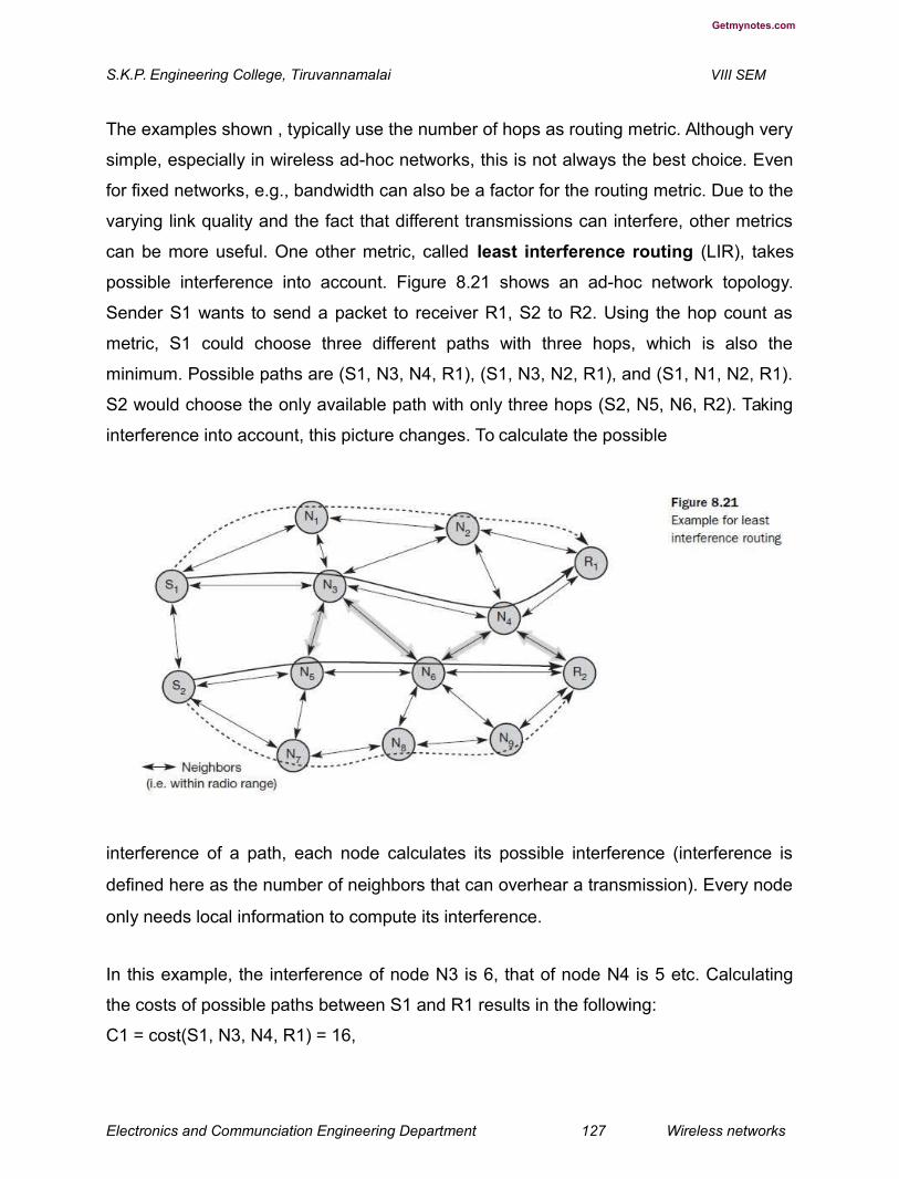
Getmynotes.com
S.K.P. Engineering College, Tiruvannamalai VIII SEM
The examples shown , typically use the number of hops as routing metric. Although very
simple, especially in wireless ad-hoc networks, this is not always the best choice. Even
for fixed networks, e.g., bandwidth can also be a factor for the routing metric. Due to the
varying link quality and the fact that different transmissions can interfere, other metrics
can be more useful. One other metric, called least interference routing (LIR), takes
possible interference into account. Figure 8.21 shows an ad-hoc network topology.
Sender S1 wants to send a packet to receiver R1, S2 to R2. Using the hop count as
metric, S1 could choose three different paths with three hops, which is also the
minimum. Possible paths are (S1, N3, N4, R1), (S1, N3, N2, R1), and (S1, N1, N2, R1).
S2 would choose the only available path with only three hops (S2, N5, N6, R2). Taking
interference into account, this picture changes. To calculate the possible
interference of a path, each node calculates its possible interference (interference is
defined here as the number of neighbors that can overhear a transmission). Every node
only needs local information to compute its interference.
In this example, the interference of node N3 is 6, that of node N4 is 5 etc. Calculating
the costs of possible paths between S1 and R1 results in the following:
C1 = cost(S1, N3, N4, R1) = 16,
Electronics and Communciation Engineering Department 127 Wireless networks
Getmynotes.com
S.K.P. Engineering College, Tiruvannamalai VIII SEM
C2 = cost(S1, N3, N2, R1) = 15,
and C3 = cost(S1, N1, N2, R1) = 12.
All three paths have the same number of hops, but the last path has the lowest cost due
to interference. Thus, S1 chooses (S1, N1, N2, R1). S2 also computes the cost of
different paths, examples are C4 = cost(S2, N5, N6, R2) = 16 and C5 = cost(S2, N7,
N8, N9, R2) = 15. S2 would, therefore, choose the path (S2, N7, N8, N9, R2), although
this path has one hop more than the first one.
With both transmissions taking place simultaneously, there would have been
interference between them as shown in Figure 8.21. In this case, least interference
routing helped to avoid interference. Taking only local decisions and not knowing what
paths other transmissions take, this scheme can just lower the probability of
interference. Interference can only be avoided if all
senders know of all other transmissions (and the whole routing topology) and base
routing on this knowledge.
Routing can take several metrics into account at the same time and weigh them. Metrics
could be the number of hops h, interference i, reliability r, error rate e etc. The cost of a
path could then be determined as:
cost = αh + βi + γr + δe + ...
It is not at all easy (if even possible) to choose the weights α, β, γ, δ,... to achieve the
desired routing behavior.
14.Brief about the Overview of ad-hoc routing protocols in detail. (L-1,CO-2)
As already mentioned, ad-hoc networking has attracted a lot of research over the last
few years. This has led to the development of many new routing algorithms. They all
come with special pros and cons (Royer, 1999), (Perkins, 2001a). Hong (2002)
Electronics and Communciation Engineering Department 128 Wireless networks

Getmynotes.com
S.K.P. Engineering College, Tiruvannamalai VIII SEM
separates them into three categories: flat routing, hierarchical routing, and geographic-
position-assisted routing.
Flat ad-hoc routing
Flat ad-hoc routing protocols comprise those protocols that do not set up hierarchies
with clusters of nodes, special nodes acting as the head of a cluster, or different routing
algorithms inside or outside certain regions. All nodes in this approach play an equal
role in routing. The addressing scheme is flat.
This category again falls into two subcategories: proactive and reactive protocols.
Proactive protocols set up tables required for routing regardless of any traffic that
would require routing functionality. DSDV, as presented in section 8.3.2 is a classic
member of this group. Many protocols belonging to this group are based on a link-state
algorithm as known from fixed networks. Link-state algorithms flood their information
about neighbors periodically or event triggered (Kurose, 2003). In mobile ad-hoc
environments this method exhibits severe drawbacks: either updating takes place often
enough to reflect the actual configuration of the network or it tries to minimize network
load. Both goals cannot be achieved at the same time without additional mechanisms.
Fisheye state routing (FSR, Pei, 2000) and fuzzy sighted link-state (FSLS,
Santivanez, 2001) attack this problem by making the update period dependent on the
distance to a certain hop. Routing entries corresponding to a faraway destination are
propagated with lower frequency than those corresponding to nearby destinations. The
result are routing tables that reflect the proximity of a node very precisely, while
imprecise entries may exist for nodes further away. Other link-state protocols that try to
reduce the traffic caused by link-state information dissemination are topology
broadcast based on reverse path forwarding (TBRPF, Ogier, 2002) and optimized
link-state routing (OLSR, Clausen, 2002). A general advantage of proactive protocols
is that they can give QoS guarantees related to connection set-up, latency or other
realtime requirements. As long as the topology does not change too fast, the routing
tables reflect the current topology with a certain precision. The propagation
Electronics and Communciation Engineering Department 129 Wireless networks

Getmynotes.com
S.K.P. Engineering College, Tiruvannamalai VIII SEM
characteristics (delay, bandwidth etc.) of a certain path between a sender and a receiver
are already known before a data packet is sent. A big disadvantage of proactive
schemes are their overheads in lightly loaded networks. Independent of any real
communication the algorithm continuously updates the routing tables. This generates a
lot of unnecessary traffic and drains the batteries of mobile devices.
Reactive protocols try to avoid this problem by setting up a path between sender and
receiver only if a communication is waiting. The two most prominent members of this
group are dynamic source routing (DSR, Johnson, 1996), as presented in section
8.3.3, and ad-hoc on-demand distance vector (AODV, Perkins, 2001a), an on-
demand version of DSDV. AODV acquires and maintains routes only on demand like
DSR does. A comparison of both protocols is given in Perkins (2001b), while Maltz
(2001) gives some actual measurements done with DSR. Both protocols, DSR and
AODV, are the leading candidates for standardization in the IETF. However, up to now
there seems to be no clear winner. A dozen more reactive protocols already exist (Hong,
2002). A clear advantage of on-demand protocols is scalability as long as there is only
light traffic and low mobility. Mobile devices can utilize longer low-power periods as they
only have to wake up for data transmission or route discovery. However, these protocols
also exhibit disadvantages. The initial search latency may degrade the performance of
interactive applications and the quality of a path is not known a priori. Route caching, a
mechanism typically employed by on-demand protocols, proves useless in high mobility
situations as routes change too frequently
Hierarchical ad-hoc routing
Algorithms such as DSDV, AODV, and DSR only work for a smaller number of nodes
and depend heavily on the mobility of nodes. For larger networks, clustering of nodes
and using different routing algorithms between and within clusters can be a scalable
and efficient solution. The motivation behind this approach is the locality property,
meaning that if a cluster can be established, nodes typically remain within a cluster, only
some change clusters. If the topology within a cluster changes, only nodes of the cluster
Electronics and Communciation Engineering Department 130 Wireless networks
Getmynotes.com
S.K.P. Engineering College, Tiruvannamalai VIII SEM
have to be informed. Nodes of other clusters only need to know how to reach the
cluster. The approach basically hides all the small details in clusters which are further
away. From time to time each node needs to get some information about the topology.
Again, updates from clusters further away will be sent out less frequently compared to
local updates. Clusters can be combined to form super clusters etc., building up a larger
hierarchy. Using this approach, one or more nodes can act as clusterheads,
representing a router for all traffic to/from the cluster. All nodes within the cluster and all
other clusterheads use these as gateway for the cluster. Figure 8.22 shows an ad-hoc
network with interconnection to the internet via a base station. This base station
transfers data to and from the cluster heads. In this example, one cluster head also acts
as head of the super cluster, routing traffic to and from the super cluster. Different
routing protocols may be used inside and outside clusters. Clusterhead-Gateway
Switch Routing (CGSR, Chiang, 1997) is a typical representative of hierarchical
routing algorithms based on distance vector (DV) routing (Kurose, 2003). Compared to
DV protocols, the hierarchy helps to reduce routing tables tremendously. However, it
might be difficult to maintain
Electronics and Communciation Engineering Department 131 Wireless networks
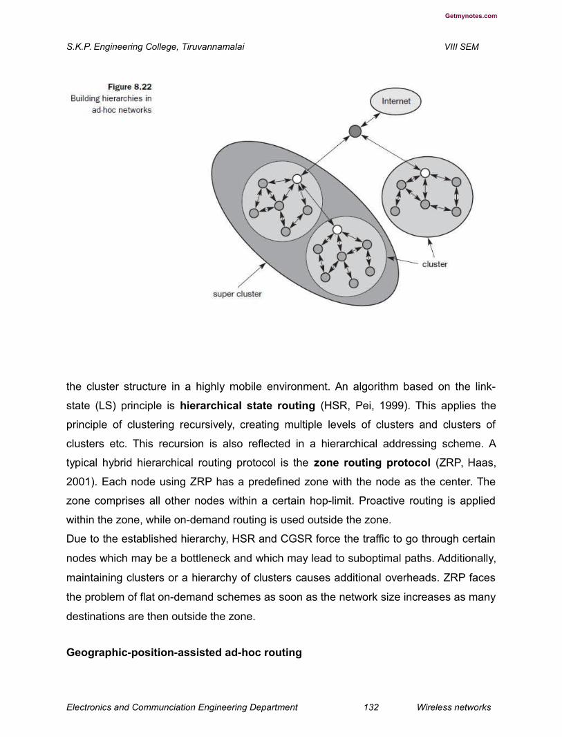
Getmynotes.com
S.K.P. Engineering College, Tiruvannamalai VIII SEM
the cluster structure in a highly mobile environment. An algorithm based on the link-
state (LS) principle is hierarchical state routing (HSR, Pei, 1999). This applies the
principle of clustering recursively, creating multiple levels of clusters and clusters of
clusters etc. This recursion is also reflected in a hierarchical addressing scheme. A
typical hybrid hierarchical routing protocol is the zone routing protocol (ZRP, Haas,
2001). Each node using ZRP has a predefined zone with the node as the center. The
zone comprises all other nodes within a certain hop-limit. Proactive routing is applied
within the zone, while on-demand routing is used outside the zone.
Due to the established hierarchy, HSR and CGSR force the traffic to go through certain
nodes which may be a bottleneck and which may lead to suboptimal paths. Additionally,
maintaining clusters or a hierarchy of clusters causes additional overheads. ZRP faces
the problem of flat on-demand schemes as soon as the network size increases as many
destinations are then outside the zone.
Geographic-position-assisted ad-hoc routing
Electronics and Communciation Engineering Department 132 Wireless networks
Getmynotes.com
S.K.P. Engineering College, Tiruvannamalai VIII SEM
If mobile nodes know their geographical position this can be used for routing purposes.
This improves the overall performance of routing algorithms if geographical proximity
also means radio proximity (which is typically, but not always, the case – just think of
obstacles between two close-by nodes). One way to acquire position information is via
the global positioning system (GPS). Mauve (2001) gives an overview of several
position-based ad-hoc routing protocols. GeoCast (Navas, 1997) allows messages to
be sent to all nodes in a specific region. This is done using addresses based on
geographic information instead of logical numbers. Additionally, a hierarchy of
geographical routers can be employed which are responsible for regions of different
scale. The locationaided routing protocol (LAR, Ko, 2000) is similar to DSR, but limits
route discovery to certain geographical regions. Another protocol that is based on
location information is greedy perimeter stateless routing (GPSR, Karp, 2000). This
uses only the location information of neighbors that are exchanged via periodic beacon
messages or via piggybacking in data packets. The main scheme of the protocol, which
is the greedy part, is quite simple. Packets are always forwarded to the neighbor that is
geographically closest to the destination. Additional mechanisms are applied if a dead
end is reached (no neighbor is closer to the destination than the node currently holding
the data packet to be forwarded).
UNIT-III
PART A
1. What do you meant by slow start? (L-1,CO-3)
TCP’s reaction to a missing acknowledgement is quite drastic, but it is necessary
to get rid of congestion quickly. The behavior TCP shows after the detection of
congestion is called slow start.
Electronics and Communciation Engineering Department 133 Wireless networks

Getmynotes.com
S.K.P. Engineering College, Tiruvannamalai VIII SEM
2.How the fast retransmit works? (L-3,CO-3)
The gap in the packet stream is not due to severe congestion, but a simplepacket loss due to a transmission error. The sender can now retransmit themissing packet(s) before the timer expires. This behaviour is called fastretransmit
3.How the destination correspondent host works? (h-1,CO-3)
Data transfer from the mobile host with destination correspondent host worksas follows. The foreign agent snoops into the packet stream to detect gaps in thesequence numbers of TCP. As soon as the foreign agent detects a missingpacket, it returns a negative acknowledgement (NACK) to the mobile host. Themobile host can now retransmit the missing packet immediately. Reordering ofpackets is done automatically at the correspondent host by TCP
4. Explain about M-TCP. (L-1,CO-3)
The M-TCP (mobile TCP)1 approach has the same goals as I-TCP and snooping
TCP: to prevent the sender window from shrinking if bit errors or disconnection but
not congestion cause current problems. M-TCP wants to improve overall
throughput, to lower the delay, to maintain end-to-end semantics of TCP, and to
provide a more efficient handover. Additionally, M-TCP is especially adapted to the
problems arising from lengthy or frequent disconnections (Brown, 1997).
5. Write the advantages of fast transmit/ Recovery operation? (L-3,CO-3)
The advantage of this approach is its simplicity. Only minor changes in the mobile
host’s software already result in a performance increase. No foreign agent or
correspondent host has to be changed.
6. Write the disadvantages of fast transmit/ Recovery operation? (L-1,CO-3)
The main disadvantage of this scheme is the insufficient isolation of packet losses.Forcing fast retransmission increases the efficiency, but retransmitted packets stillhave to cross the whole network between correspondent host and mobile host. If thehandover from one foreign agent to another takes a longer time, the correspondenthost will have already started retransmission.
7. Write the advantages of Transmission/time-out freezing operation? (L-1,CO-
3)
Electronics and Communciation Engineering Department 134 Wireless networks

Getmynotes.com
S.K.P. Engineering College, Tiruvannamalai VIII SEM
The advantage of this approach is that it offers a way to resume TCP connectionseven after longer interruptions of the connection. It is independent of any other TCPmechanism, such as acknowledgements or sequence numbers, so it can be usedtogether with encrypted data.
8. Write the disadvantages of Transmission/time-out freezing operation? (L-
1,CO-3)
Not only does the software on the mobile host have to be changed, to be more
effective the correspondent host cannot remain unchanged. All mechanisms rely on
the capability of the MAC layer to detect future interruptions. Freezing the state of TCP
does not help in case of some encryption schemes that use time-dependent random
numbers. These schemes need resynchronization after interruption.
9. Write the advantages of Selective transmission freezing operation? (L-1,CO-3)
The advantage of this approach is obvious: a sender retransmits only the lost packets.
This lowers bandwidth requirements and is extremely helpful in slow wireless links. The
gain in efficiency is not restricted to wireless links and mobile environments. Using
selective retransmission is also beneficial in all other networks.
10.Write the advantages of Selective transmission freezing operation? (L-
1,CO-3) However, there might be the minor disadvantage of more complex
software on the receiver side, because now more buffer is necessary to
resequence data and to wait for gaps to be filled. But while memory sizes and
CPU performance permanently increase, the bandwidth of the air interface
remains almost the same. Therefore, the higher complexity is no real
disadvantage any longer as it was in the early days of TCP.
11.Give short notes about ECN. (L-1,CO-3)
Explicit Congestion Notification (ECN): ECN as defined in RFC 3168 allows a
receiver to inform a sender of congestion in the network by setting the ECN-Echo flag
on receiving an IP packet that has experienced congestion. This mechanism makes it
easier to distinguish packet loss due to transmission errors from packet loss due to
congestion. However, this can only be achieved when ECN capable routers are
deployed in the network.
Electronics and Communciation Engineering Department 135 Wireless networks

Getmynotes.com
S.K.P. Engineering College, Tiruvannamalai VIII SEM
12.What happens to standard TCP in the case of disconnection? (L-2,CO-3)
A TCP sender tries to retransmit data controlled by a retransmission timer that doubles
with each unsuccessful retransmission attempt, up to a maximum of one minute (the
initial value depends on the round trip time). This means that the sender tries to
retransmit an unacknowledged packet every minute and will give up after 12
retransmissions.
13. What happens if connectivity is back earlier than this? (H-1,CO-3)
No data is successfully transmitted for a period of one minute! The retransmission time-
out is still valid and the sender has to wait. The sender also goes into slow-start
because it assumes congestion.
14. Draw the overview of classical enhancements to TCP for mobility. (L-1,CO-3)
Electronics and Communciation Engineering Department 136 Wireless networks

Getmynotes.com
S.K.P. Engineering College, Tiruvannamalai VIII SEM
PART B
1.Explain in detail about Traditional TCP and its siginificance. (L-1,CO-3)
Congestion control
Electronics and Communciation Engineering Department 137 Wireless networks

Getmynotes.com
S.K.P. Engineering College, Tiruvannamalai VIII SEM
A transport layer protocol such as TCP has been designed for fixed networks with fixed
end-systems. Data transmission takes place using network adapters, fiber optics,
copper wires, special hardware for routers etc. This hardware typically works without
introducing transmission errors. If the software is mature enough, it will not drop packets
or flip bits, so if a packet on its way from a sender to a receiver is lost in a fixed network,
it is not because of hardware or software errors. The probable reason for a packet loss
in a fixed network is a temporary overload some point in the transmission path, i.e., a
state of congestion at a node. Congestion may appear from time to time even in
carefully designed networks.
The packet buffers of a router are filled and the router cannot forward the packets fast
enough because the sum of the input rates of packets destined for one output link is
higher than the capacity of the output link. The only thing a router can do in this situation
is to drop packets. A dropped packet is lost for the transmission, and the receiver
notices a gap in the packet stream.Now the receiver does not directly tell the sender
which packet is missing, but continues to acknowledge all in-sequence packets up to
the missing one. The sender notices the missing acknowledgement for the lost packet
and assumes a packet loss due to congestion. Retransmitting the missing packet and
continuing at full sending rate would now be unwise, as this might only increase the
congestion. Although it is not guaranteed that all packets of the
TCP connection take the same way through the network, this assumption holds for most
of the packets. To mitigate congestion, TCP slows down the transmission rate
dramatically. All other TCP connections experiencing the same congestion do exactly
the same so the congestion is soon resolved. This cooperation of TCP connections in
the internet is one of the main reasons for its survival as it is today. Using UDP is not a
solution, because the throughput is higher compared to a TCP connection just at the
beginning. As soon as everyone uses UDP, this advantage disappears. After that,
congestion is standard and data transmission quality is unpredictable. Even under
heavy load, TCP guarantees at least sharing of the bandwidth.
Slow start
Electronics and Communciation Engineering Department 138 Wireless networks
Getmynotes.com
S.K.P. Engineering College, Tiruvannamalai VIII SEM
TCP’s reaction to a missing acknowledgement is quite drastic, but it is necessary to get
rid of congestion quickly. The behavior TCP shows after the detection of congestion is
called slow start (Kurose, 2003). The sender always calculates a congestion window
for a receiver. The start size of the congestion window is one segment (TCP packet).
The sender sends one packet and waits for acknowledgement. If this acknowledgement
arrives, the sender increases the congestion window by one, now sending two packets
(congestion window = 2). After arrival of the two corresponding acknowledgements, the
sender again adds 2 to the congestion window, one for each of the acknowledgements.
Now the congestion window equals 4. This scheme doubles the congestion window
every time the acknowledgements come back, which takes one round trip time (RTT).
This is called the exponential growth of the congestion window in the slow start
mechanism. It is too dangerous to double the congestion window each time because
the steps might become too large. The exponential growth stops at the congestion
threshold. As soon as the congestion window reaches the congestion threshold, further
increase of the transmission rate is only linear by adding 1 to the congestion window
each time the acknowledgements come back. Linear increase continues until a time-out
at the sender occurs due to a missing acknowledgement, or until the sender detects a
gap in transmitted data because of continuous acknowledgements for the same packet.
In either case the sender sets the congestion threshold to half of the current congestion
window. The congestion window itself is set to one segment and the sender starts
sending a single segment. The exponential growth (as described above) starts once
more up to the new congestion threshold, then the window grows in linear fashion.
Fast retransmit/fast recovery
Two things lead to a reduction of the congestion threshold. One is a sender receiving
continuous acknowledgements for the same packet. This informs the sender of two
things. One is that the receiver got all packets up to the acknowledged packet in
sequence. In TCP, a receiver sends acknowledgements only if it receives any packets
from the sender. Receiving acknowledgements from a receiver also shows that the
Electronics and Communciation Engineering Department 139 Wireless networks

Getmynotes.com
S.K.P. Engineering College, Tiruvannamalai VIII SEM
receiver continuously receives something from the sender. The gap in the packet
stream is not due to severe congestion, but a simple packet loss due to a transmission
error. The sender can now retransmit the missing packet(s) before the timer expires.
This behavior is called fast retransmit (Kurose, 2003).
The receipt of acknowledgements shows that there is no congestion to justify a slow
start. The sender can continue with the current congestion window. The sender
performs a fast recovery from the packet loss. This mechanism can improve the
efficiency of TCP dramatically.
The other reason for activating slow start is a time-out due to a missing
acknowledgement. TCP using fast retransmit/fast recovery interprets this congestion in
the network and activates the slow start mechanism.
Implications on mobility
While slow start is one of the most useful mechanisms in fixed networks, it drastically
decreases the efficiency of TCP if used together with mobile receivers or senders. The
reason for this is the use of slow start under the wrong assumptions. From a missing
acknowledgement, TCP concludes a congestion situation. While this may also happen
in networks with mobile and wireless end-systems, it is not the main reason for packet
loss.
Error rates on wireless links are orders of magnitude higher compared to fixed fiber or
copper links. Packet loss is much more common and cannot always be compensated
for by layer 2 retransmissions (ARQ) or error correction (FEC). Trying to retransmit on
layer 2 could, for example, trigger TCP retransmission if it takes too long. Layer 2 now
faces the problem of transmitting the same packet twice over a bad link. Detecting these
duplicates on layer 2 is not
an option, because more and more connections use end-to-end encryption, making it
impossible to look at the packet.
Electronics and Communciation Engineering Department 140 Wireless networks
Getmynotes.com
S.K.P. Engineering College, Tiruvannamalai VIII SEM
Mobility itself can cause packet loss. There are many situations where a soft handover
from one access point to another is not possible for a mobile endsystem. For example,
when using mobile IP, there could still be some packets in transit to the old foreign
agent while the mobile node moves to the new foreign agent. The old foreign agent may
not be able to forward those packets to the new foreign agent or even buffer the packets
if disconnection of the mobile node takes too long. This packet loss has nothing to do
with wireless access but is caused by the problems of rerouting traffic. The TCP
mechanism detecting missing acknowledgements via time-outs
and concluding packet loss due to congestion cannot distinguish between the different
causes. This is a fundamental design problem in TCP: An error control mechanism
(missing acknowledgement due to a transmission error) is misused for congest on
control (missing acknowledgement due to network overload). In both cases packets are
lost (either due to invalid checksums or to dropping in routers). However, the reasons
are completely different. TCP cannot distinguish between these two different reasons.
Explicit congestion notification (ECN) mechanisms are currently discussed and some
recommendations have been already given (RFC 3168, Ramakrishnan, 2001).
However, RFC 3155 (Dawkins, 2001b) states that ECN cannot be used as surrogate for
explicit transmission error notification. Standard TCP reacts with slow start if
acknowledgements are missing, which does not help in the case of transmission errors
over wireless links and which does not really help during handover. This behavior
results in a severe performance degradation of an unchanged TCP if used together with
wireless links or mobile nodes.
However, one cannot change TCP completely just to support mobile users or wireless
links. The same arguments that were given to keep IP unchanged also apply to TCP.
The installed base of computers using TCP is too large to be changed and, more
important, mechanisms such as slow start keep the internet
operable. Every enhancement to TCP, therefore, has to remain compatible with the
standard TCP and must not jeopardize the cautious behavior of TCP in case of
Electronics and Communciation Engineering Department 141 Wireless networks
Getmynotes.com
S.K.P. Engineering College, Tiruvannamalai VIII SEM
congestion. The following sections present some classical solutions before discussing
current TCP tuning recommendations.
2. Brief in detail about Classical TCP improvements in the WLANs.(L-2,CO-3)
Together with the introduction of WLANs in the mid-nineties several research projects
were started with the goal to increase TCP’s performance in wireless and mobile
environments.
Indirect TCP
Two competing insights led to the development of indirect TCP (I-TCP) (Bakre, 1995).
One is that TCP performs poorly together with wireless links; the other is that TCP within
the fixed network cannot be changed. I-TCP segments a TCP connection into a fixed
part and a wireless part. Figure 9.1 shows an example with a mobile host connected via
a wireless link and an access point to the ‘wired’ internet where the correspondent host
resides. The correspondent node could also use wireless access. The following would
then also be applied to the access link of the correspondent host.
Standard TCP is used between the fixed computer and the access point. No computer
in the internet recognizes any changes to TCP. Instead of the mobile host, the access
point now terminates the standard TCP connection, acting as a proxy. This means that
the access point is now seen as the mobile host for the fixed host and as the fixed host
for the mobile host. Between the access point and the mobile host, a special TCP,
adapted to wireless links, is used. However,
changing TCP for the wireless link is not a requirement. Even an unchanged TCP can
benefit from the much shorter round trip time, starting retransmission much faster. A
good place for segmenting the connection between mobile host and correspondent host
is at the foreign agent of mobile IP . The foreign agent controls the mobility of the mobile
host anyway and can also hand over the connection to the next foreign agent when the
mobile host
Electronics and Communciation Engineering Department 142 Wireless networks
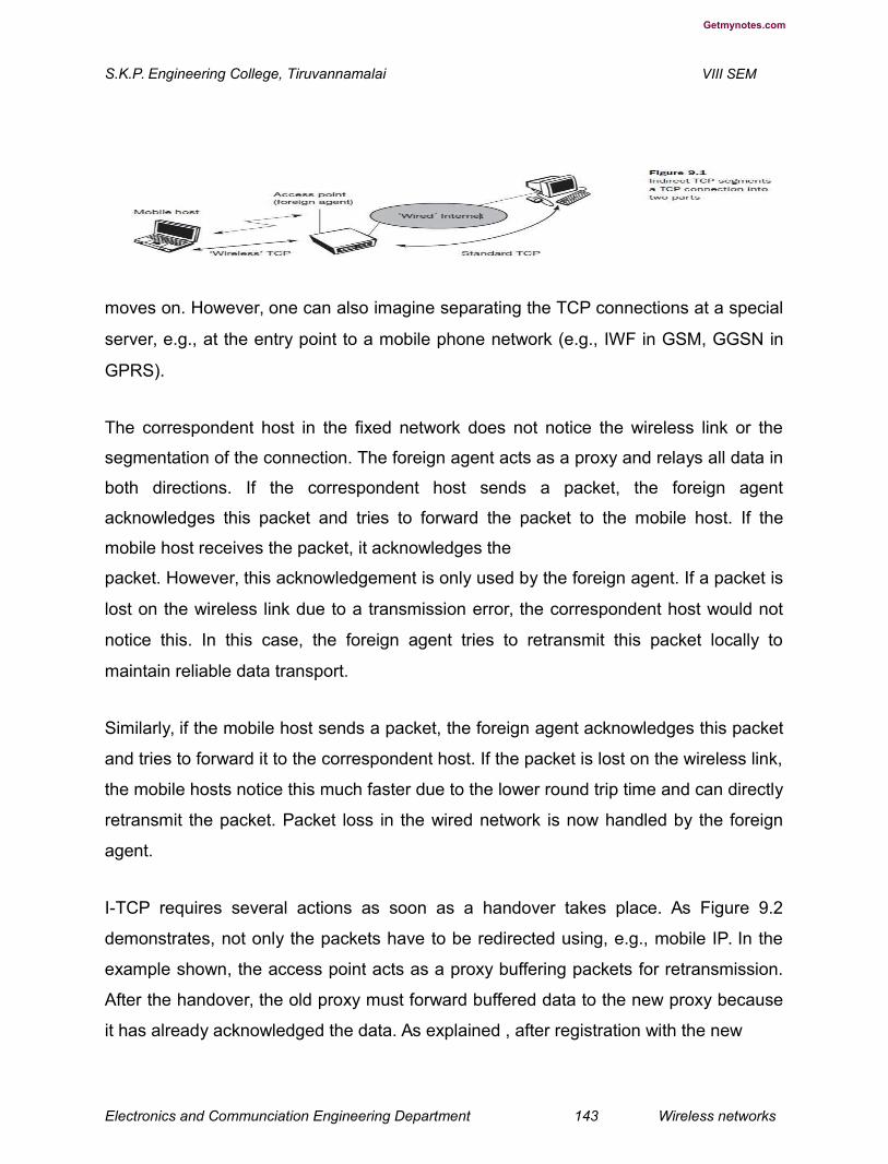
Getmynotes.com
S.K.P. Engineering College, Tiruvannamalai VIII SEM
moves on. However, one can also imagine separating the TCP connections at a special
server, e.g., at the entry point to a mobile phone network (e.g., IWF in GSM, GGSN in
GPRS).
The correspondent host in the fixed network does not notice the wireless link or the
segmentation of the connection. The foreign agent acts as a proxy and relays all data in
both directions. If the correspondent host sends a packet, the foreign agent
acknowledges this packet and tries to forward the packet to the mobile host. If the
mobile host receives the packet, it acknowledges the
packet. However, this acknowledgement is only used by the foreign agent. If a packet is
lost on the wireless link due to a transmission error, the correspondent host would not
notice this. In this case, the foreign agent tries to retransmit this packet locally to
maintain reliable data transport.
Similarly, if the mobile host sends a packet, the foreign agent acknowledges this packet
and tries to forward it to the correspondent host. If the packet is lost on the wireless link,
the mobile hosts notice this much faster due to the lower round trip time and can directly
retransmit the packet. Packet loss in the wired network is now handled by the foreign
agent.
I-TCP requires several actions as soon as a handover takes place. As Figure 9.2
demonstrates, not only the packets have to be redirected using, e.g., mobile IP. In the
example shown, the access point acts as a proxy buffering packets for retransmission.
After the handover, the old proxy must forward buffered data to the new proxy because
it has already acknowledged the data. As explained , after registration with the new
Electronics and Communciation Engineering Department 143 Wireless networks
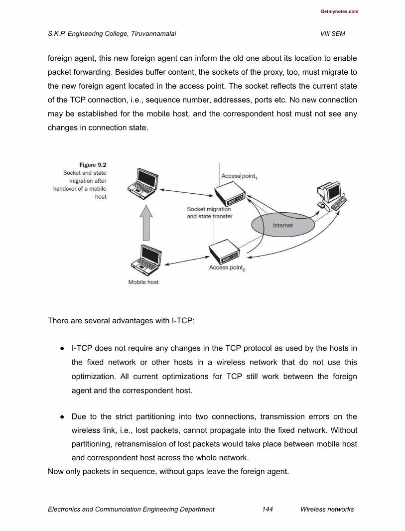
Getmynotes.com
S.K.P. Engineering College, Tiruvannamalai VIII SEM
foreign agent, this new foreign agent can inform the old one about its location to enable
packet forwarding. Besides buffer content, the sockets of the proxy, too, must migrate to
the new foreign agent located in the access point. The socket reflects the current state
of the TCP connection, i.e., sequence number, addresses, ports etc. No new connection
may be established for the mobile host, and the correspondent host must not see any
changes in connection state.
There are several advantages with I-TCP:
● I-TCP does not require any changes in the TCP protocol as used by the hosts in
the fixed network or other hosts in a wireless network that do not use this
optimization. All current optimizations for TCP still work between the foreign
agent and the correspondent host.
● Due to the strict partitioning into two connections, transmission errors on the
wireless link, i.e., lost packets, cannot propagate into the fixed network. Without
partitioning, retransmission of lost packets would take place between mobile host
and correspondent host across the whole network.
Now only packets in sequence, without gaps leave the foreign agent.
Electronics and Communciation Engineering Department 144 Wireless networks

Getmynotes.com
S.K.P. Engineering College, Tiruvannamalai VIII SEM
● It is always dangerous to introduce new mechanisms into a huge network such
as the internet without knowing exactly how they will behave. However, new
mechanisms are needed to improve TCP performance (e.g., disabling slow start
under certain circumstances), but with I-TCP only between the mobile host and
the foreign agent. Different solutions can be tested or used at the same time
without jeopardizing the stability of the internet. Furthermore, optimizing of these
new mechanisms is quite simple because they only cover one single hop.
● The authors assume that the short delay between the mobile host and foreign
agent could be determined and was independent of other traffic streams. An
optimized TCP could use precise time-outs to guarantee retransmission as fast
as possible. Even standard TCP could benefit from the short round trip time, so
recovering faster from packet loss. Delay is much higher in a typical wide area
wireless network than in wired networks due to FEC and MAC. GSM has a delay
of up to 100 ms circuit switched, 200 ms and more packet switched (depending
on packet size and current traffic). This is even higher than the delay on
transatlantic links.
● Partitioning into two connections also allows the use of a different transport layer
protocol between the foreign agent and the mobile host or the use of compressed
headers etc. The foreign agent can now act as a gateway to translate between
the different protocols. But the idea of segmentation in I-TCP also comes with
some disadvantages:
● The loss of the end-to-end semantics of TCP might cause problems if the foreign
agent partitioning the TCP connection crashes. If a sender receives an
acknowledgement, it assumes that the receiver got the packet. Receiving an
acknowledgement now only means (for the mobile host and a correspondent
host) that the foreign agent received the packet. The correspondent node does
not know anything about the partitioning, so a crashing access node may also
crash applications running on the correspondent node assuming reliable end-to-
end delivery.

Electronics and Communciation Engineering Department 145 Wireless networks
Getmynotes.com
S.K.P. Engineering College, Tiruvannamalai VIII SEM
In practical use, increased handover latency may be much more problematic. All
packets sent by the correspondent host are buffered by the foreign agent besides
forwarding them to the mobile host (if the TCP connection is split at the foreign agent).
The foreign agent removes a packet from the buffer as soon as the appropriate
acknowledgement arrives. If the mobile host now performs a handover to another
foreign agent, it takes a while before the old foreign agent can forward the buffered data
to the new foreign agent. During this time more packets may arrive. All these packets
have to be forwarded to the new foreign agent first, before it can start forwarding the
new packets redirected to it.
● The foreign agent must be a trusted entity because the TCP connections end at
this point. If users apply end-to-end encryption, e.g., according to RFC 2401
(Kent, 1998a), the foreign agent has to be integrated into all security
mechanisms.
Snooping TCP
One of the drawbacks of I-TCP is the segmentation of the single TCP connection into
two TCP connections. This loses the original end-to-end TCP semantic. The following
TCP enhancement works completely transparently and leaves the TCP end-to-end
connection intact. The main function of the enhancement is to buffer data close to the
mobile host to perform fast local retransmission in case of packet loss. A good place for
the enhancement of TCP could be the foreign agent in the Mobile IP context (see Figure
9.3). In this approach, the foreign agent buffers all packets with destination mobile
host and additionally ‘snoops’ the packet flow in both directions to recognize
acknowledgements (Balakrishnan, 1995), (Brewer, 1998). The reason for buffering
packets toward the mobile node is to enable the foreign agent to perform a local
retransmission in case of packet loss on the wireless link. The foreign agent buffers
every packet until it receives an acknowledgement from the mobile host. If the foreign
agent does not receive an acknowledgement from the mobile host within a certain
amount of time, either the packet or the acknowledgement has been lost. Alternatively,
Electronics and Communciation Engineering Department 146 Wireless networks


Getmynotes.com
S.K.P. Engineering College, Tiruvannamalai VIII SEM
the foreign agent could receive a duplicate ACK which also shows the loss of a packet.
Now the foreign agent
retransmits the packet directly from the buffer, performing a much faster retransmission
compared to the correspondent host. The time out for acknowledgements can be much
shorter, because it reflects only the delay of one hop plus processing time.
To remain transparent, the foreign agent must not acknowledge data to the
correspondent host. This would make the correspondent host believe that the mobile
host had received the data and would violate the end-to-end semantic in case of a
foreign agent failure. However, the foreign agent can filter the duplicate
acknowledgements to avoid unnecessary retransmissions of data from the
correspondent host. If the foreign agent now crashes, the time-out of the correspondent
host still works and triggers a retransmission. The foreign agent may discard duplicates
of packets already retransmitted locally and acknowledged by the mobile host. This
avoids unnecessary traffic on the wireless link. Data transfer from the mobile host with
destination correspondent host works as follows. The foreign agent snoops into the
packet stream to detect gaps in the sequence numbers of TCP. As soon as the foreign
agent detects a missing packet, it returns a negative acknowledgement (NACK) to the
mobile host. The mobile host can now retransmit the missing packet immediately.
Reordering of packets is done automatically at the correspondent host by TCP.
Electronics and Communciation Engineering Department 147 Wireless networks

Getmynotes.com
S.K.P. Engineering College, Tiruvannamalai VIII SEM
Extending the functions of a foreign agent with a ‘snooping’ TCP has several
advantages:
● The end-to-end TCP semantic is preserved. No matter at what time the foreign
agent crashes (if this is the location of the buffering and snooping mechanisms),
neither the correspondent host nor the mobile host have an inconsistent view of
the TCP connection as is possible with I-TCP. The approach automatically falls
back to standard TCP if the enhancements stop working.
● The correspondent host does not need to be changed; most of the
enhancements are in the foreign agent. Supporting only the packet stream from
the correspondent host to the mobile host does not even require changes in the
mobile host.
● It does not need a handover of state as soon as the mobile host moves to
another foreign agent. Assume there might still be data in the buffer not
transferred to the next foreign agent. All that happens is a time-out at the
correspondent host and retransmission of the packets, possibly already to the
new care-of address.
● It does not matter if the next foreign agent uses the enhancement or not. If not,
the approach automatically falls back to the standard solution. This is one of the
problems of I-TCP, since the old foreign agent may have already signaled the
correct receipt of data via acknowledgements to the correspondent host and now
has to transfer these packets to the mobile host via the new foreign agent.
However, the simplicity of the scheme also results in some disadvantages:
● Snooping TCP does not isolate the behavior of the wireless link as well as ITCP.
Assume, for example, that it takes some time until the foreign agent can
successfully retransmit a packet from its buffer due to problems on the wireless
link (congestion, interference). Although the time-out in the foreign agent may be
much shorter than the one of the correspondent host, after a while the time-out in
the correspondent host
Electronics and Communciation Engineering Department 148 Wireless networks
Getmynotes.com
S.K.P. Engineering College, Tiruvannamalai VIII SEM
triggers a retransmission. The problems on the wireless link are now also visible for the
correspondent host and not fully isolated. The quality of the isolation, which snooping
TCP offers, strongly depends on the quality of the wireless link, time-out values, and
further traffic characteristics. It is problematic that the wireless link exhibits very high
delays compared to the wired link due to error correction on layer 2 (factor 10 and more
higher). This is similar to ITCP. If this is the case, the timers in the foreign agent and the
correspondent host are almost equal and the approach is almost ineffective.
● Using negative acknowledgements between the foreign agent and the mobile
host assumes additional mechanisms on the mobile host. This approach is no
longer transparent for arbitrary mobile hosts.
● All efforts for snooping and buffering data may be useless if certain encryption
schemes are applied end-to-end between the correspondent host and mobile
host. Using IP encapsulation security payload (RFC 2406, (Kent, 1998b)) the
TCP protocol header will be encrypted – snooping on the sequence numbers will
no longer work. Retransmitting data from the foreign
agent may not work because many security schemes prevent replay attacks –
retransmitting data from the foreign agent may be misinterpreted as replay. Encrypting
end-to-end is the way many applications work so it is not clear how this scheme could
be used in the future. If encryption is used above the transport layer (e.g., SSL/TLS)
snooping TCP can be used.
3. How the Mobile TCP is playing the important role in Mobile transport layer?
(L-1,CO-3)
Dropping packets due to a handover or higher bit error rates is not the only
phenomenon of wireless links and mobility – the occurrence of lengthy and/or frequent
disconnections is another problem. Quite often mobile users cannot connect at all. One
example is islands of wireless LANs inside buildings but no coverage of the whole
campus. What happens to standard TCP in the case of disconnection?A TCP sender
Electronics and Communciation Engineering Department 149 Wireless networks
Getmynotes.com
S.K.P. Engineering College, Tiruvannamalai VIII SEM
tries to retransmit data controlled by a retransmission timer that doubles with each
unsuccessful retransmission attempt, up to a maximum of one minute (the initial value
depends on the round trip time). This means that the sender tries to retransmit an
unacknowledged packet every minute and will give up after 12 retransmissions. What
happens if connectivity is back earlier than this? No data is successfully transmitted for
a period of one minute! The retransmission time-out is still valid and the sender has to
wait. The sender also goes into slow-start because it assumes congestion.
What happens in the case of I-TCP if the mobile is disconnected? The proxy has to
buffer more and more data, so the longer the period of disconnection, the more buffer is
needed. If a handover follows the disconnection, which is typical, even more state has
to be transferred to the new proxy. The snooping approach also suffers from being
disconnected. The mobile will not be able to send ACKs so, snooping cannot help in this
situation.
The M-TCP (mobile TCP)1 approach has the same goals as I-TCP and snooping TCP:
to prevent the sender window from shrinking if bit errors or disconnection but not
congestion cause current problems. M-TCP wants to improve overall throughput, to
lower the delay, to maintain end-to-end semantics of TCP, and to provide a more
efficient handover. Additionally, M-TCP is
especially adapted to the problems arising from lengthy or frequent disconnections
(Brown, 1997).
M-TCP splits the TCP connection into two parts as I-TCP does. An unmodified TCP is
used on the standard host-supervisory host (SH) connection, while an optimized TCP
is used on the SH-MH connection. The supervisory host is responsible for exchanging
data between both parts similar to the proxy in ITCP (see Figure 9.1). The M-TCP
approach assumes a relatively low bit error rate on the wireless link. Therefore, it does
not perform caching/retransmission of data via the SH. If a packet is lost on the wireless
link, it has to be retransmitted by the original sender. This maintains the TCP end-to-end
semantics. The SH monitors all packets sent to the MH and ACKs returned from the
Electronics and Communciation Engineering Department 150 Wireless networks

Getmynotes.com
S.K.P. Engineering College, Tiruvannamalai VIII SEM
MH. If the SH does not receive an ACK for some time, it assumes that the MH is
disconnected. It then chokes the sender by setting the sender’s window size to 0.
Setting the window size to 0 forces the sender to go into persistent mode, i.e., the
state of the sender will not change no matter how long the receiver is disconnected.
This means that the sender will not try to retransmit data. As soon as the SH (either the
old SH or a new SH) detects connectivity again, it reopens the window of the sender to
the old value. The sender can continue sending at full speed. This mechanism does not
require changes to the sender’s TCP. The wireless side uses an adapted TCP that can
recover from packet loss much faster. This modified TCP does not use slow start, thus,
M-TCP needs a bandwidth manager to implement fair sharing over the wireless link.
The advantages of M-TCP are the following:
● It maintains the TCP end-to-end semantics. The SH does not send any ACK itself
but forwards the ACKs from the MH.
● If the MH is disconnected, it avoids useless retransmissions, slow starts or
breaking connections by simply shrinking the sender’s window to 0.
● Since it does not buffer data in the SH as I-TCP does, it is not necessary to
forward buffers to a new SH. Lost packets will be automatically retransmitted to
the new SH.
The lack of buffers and changing TCP on the wireless part also has some
disadvantages:
● As the SH does not act as proxy as in I-TCP, packet loss on the wireless link due
to bit errors is propagated to the sender. M-TCP assumes low bit error rates,
which is not always a valid assumption.
● A modified TCP on the wireless link not only requires modifications to the MH
protocol software but also new network elements like the bandwidth manager.
Electronics and Communciation Engineering Department 151 Wireless networks

Getmynotes.com
S.K.P. Engineering College, Tiruvannamalai VIII SEM
Fast retransmit/fast recovery
As described in section 9.1.4, moving to a new foreign agent can cause packet loss or
time out at mobile hosts or corresponding hosts. TCP concludes congestion and goes
into slow start, although there is no congestion. Section 9.1.3 showed the mechanisms
of fast recovery/fast retransmit a host can use after receiving duplicate
acknowledgements, thus concluding a packet loss without congestion. The idea
presented by Caceres (1995) is to artificially force the fast retransmit behavior on the
mobile host and correspondent host side. As soon as the mobile
host registers at a new foreign agent using mobile IP, it starts sending duplicated
acknowledgements to correspondent hosts. The proposal is to send three duplicates.
This forces the corresponding host to go into fast retransmit mode and not to start slow
start, i.e., the correspondent host continues to send with the same rate it did before the
mobile host moved to another foreign agent. As the mobile host may also go into slow
start after moving to a new foreign agent, this approach additionally puts the mobile host
into fast retransmit. The mobile host retransmits all unacknowledged packets using the
current congestion window size without going into slow start.
The advantage of this approach is its simplicity. Only minor changes in the mobile
host’s software already result in a performance increase. No foreign agent or
correspondent host has to be changed.
The main disadvantage of this scheme is the insufficient isolation of packet losses.
Forcing fast retransmission increases the efficiency, but retransmitted packets still have
to cross the whole network between correspondent host and mobile host. If the
handover from one foreign agent to another takes a longer time, the correspondent host
will have already started retransmission. The
approach focuses on loss due to handover: packet loss due to problems on the wireless
link is not considered. This approach requires more cooperation between the mobile IP
and TCP layer making it harder to change one without influencing the other.
Electronics and Communciation Engineering Department 152 Wireless networks
Getmynotes.com
S.K.P. Engineering College, Tiruvannamalai VIII SEM
Transmission/time-out freezing
While the approaches presented so far can handle short interruptions of the connection,
either due to handover or transmission errors on the wireless link, some were designed
for longer interruptions of transmission. Examples are the use of mobile hosts in a car
driving into a tunnel, which loses its connection to, e.g., a satellite (however, many
tunnels and subways provide connectivity via a mobile phone), or a user moving into a
cell with no capacity left over. In this case, the mobile phone system will interrupt the
connection. The reaction of TCP, even with the enhancements of above, would be a
disconnection after a time out. Quite often, the MAC layer has already noticed
connection problems, before the connection is actually interrupted from a TCP point of
view. Additionally, the MAC layer knows the real reason for the interruption and does not
assume congestion, as TCP would. The MAC layer can inform the TCP layer of an
upcoming loss of connection or that the current interruption is not caused by congestion.
TCP can now stop sending and ‘freezes’ the current state of its congestion window and
further timers. If the MAC layer notices the upcoming interruption early enough, both the
mobile and correspondent host can be informed. With a fast interruption of the wireless
link, additional mechanisms in the access point are needed to inform the correspondent
host of the reason for interruption. Otherwise, the correspondent host goes into slow
start assuming congestion and finally breaks the connection.
As soon as the MAC layer detects connectivity again, it signals TCP that it can resume
operation at exactly the same point where it had been forced to stop. For TCP time
simply does not advance, so no timers expire. The advantage of this approach is that it
offers a way to resume TCP connections even after longer interruptions of the
connection. It is independent of any other TCP mechanism, such as acknowledgements
or sequence numbers, so it can be used together with encrypted data. However, this
scheme has some severe disadvantages. Not only does the software on the mobile
host have to be changed, to be more effective the correspondent host cannot remain
unchanged. All mechanisms rely on the capability of the MAC layer to detect
Electronics and Communciation Engineering Department 153 Wireless networks
Getmynotes.com
S.K.P. Engineering College, Tiruvannamalai VIII SEM
future interruptions. Freezing the state of TCP does not help in case of some encryption
schemes that use time-dependent random numbers. These schemes need
resynchronization after interruption.
Selective retransmission
A very useful extension of TCP is the use of selective retransmission. TCP
acknowledgements are cumulative, i.e., they acknowledge in-order receipt of packets
up to a certain packet. If a single packet is lost, the sender has to retransmit everything
starting from the lost packet (go-back-n retransmission). This obviously wastes
bandwidth, not just in the case of a mobile network, but for any network (particularly
those with a high path capacity, i.e., bandwidthdelay-product).
Using RFC 2018 (Mathis, 1996), TCP can indirectly request a selective retransmission
of packets. The receiver can acknowledge single packets, not only trains of in-sequence
packets. The sender can now determine precisely which packet is needed and can
retransmit it.
The advantage of this approach is obvious: a sender retransmits only the lost packets.
This lowers bandwidth requirements and is extremely helpful in slow wireless links. The
gain in efficiency is not restricted to wireless links and mobile environments. Using
selective retransmission is also beneficial in all other networks. However, there might be
the minor disadvantage of more complex software on the receiver side, because now
more buffer is necessary to resequence data and to wait for gaps to be filled. But while
memory sizes and
CPU performance permanently increase, the bandwidth of the air interface remains
almost the same. Therefore, the higher complexity is no real disadvantage any longer
as it was in the early days of TCP.
Electronics and Communciation Engineering Department 154 Wireless networks

Getmynotes.com
S.K.P. Engineering College, Tiruvannamalai VIII SEM
Transaction-oriented TCP
Assume an application running on the mobile host that sends a short request to a server
from time to time, which responds with a short message. If the application requires
reliable transport of the packets, it may use TCP (many applications of this kind use
UDP and solve reliability on a higher, application-oriented layer). Using TCP now
requires several packets over the wireless link. First, TCP uses a three-way handshake
to establish the connection. At least one additional
packet is usually needed for transmission of the request, and requires three more
packets to close the connection via a three-way handshake. Assuming connections with
a lot of traffic or with a long duration, this overhead is minimal. But in an example of only
one data packet, TCP may need seven packets altogether. Figure 9.4 shows an
example for the overhead introduced by using TCP over GPRS in a web scenario. Web
services are based on HTTP which requires a reliable transport system. In the internet,
TCP is used for this purpose. Before a
Electronics and Communciation Engineering Department 155 Wireless networks

Getmynotes.com
S.K.P. Engineering College, Tiruvannamalai VIII SEM
HTTP request can be transmitted the TCP connection has to be established. This
already requires three messages. If GPRS is used as wide area transport system, one-
way delays of 500 ms and more are quite common. The setup of a TCP connection
already takes far more than a second.
This led to the development of a transaction-oriented TCP (T/TCP, RFC 1644 (Braden,
1994)). T/TCP can combine packets for connection establishment and connection
release with user data packets. This can reduce the number of packets down to two
instead of seven. Similar considerations led to the development of a transaction service
in WAP.
The obvious advantage for certain applications is the reduction in the overhead which
standard TCP has for connection setup and connection release. However, T/TCP is not
the original TCP anymore, so it requires changes in the mobile host and all
correspondent hosts, which is a major disadvantage. This solution no longer hides
mobility. Furthermore, T/TCP exhibits several security problems (de Vivo, 1999).
Electronics and Communciation Engineering Department 156 Wireless networks
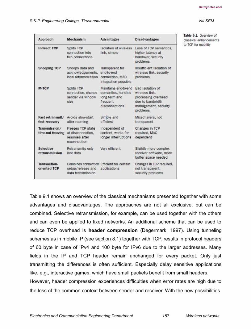
Getmynotes.com
S.K.P. Engineering College, Tiruvannamalai VIII SEM
Table 9.1 shows an overview of the classical mechanisms presented together with some
advantages and disadvantages. The approaches are not all exclusive, but can be
combined. Selective retransmission, for example, can be used together with the others
and can even be applied to fixed networks. An additional scheme that can be used to
reduce TCP overhead is header compression (Degermark, 1997). Using tunneling
schemes as in mobile IP (see section 8.1) together with TCP, results in protocol headers
of 60 byte in case of IPv4 and 100 byte for IPv6 due to the larger addresses. Many
fields in the IP and TCP header remain unchanged for every packet. Only just
transmitting the differences is often sufficient. Especially delay sensitive applications
like, e.g., interactive games, which have small packets benefit from small headers.
However, header compression experiences difficulties when error rates are high due to
the loss of the common context between sender and receiver. With the new possibilities
Electronics and Communciation Engineering Department 157 Wireless networks

Getmynotes.com
S.K.P. Engineering College, Tiruvannamalai VIII SEM
of wireless wide area networks (WWAN) and their tremendous success, the focus of
research has shifted more and more towards these 2.5G/3G networks. Up to now there
are no final solutions to the problems arising when TCP is used in WWANs. However,
some guidelines do exist.
TCP over 2.5/3G wireless networks
The current internet draft for TCP over 2.5G/3G wireless networks (Inamura, 2002)
describes a profile for optimizing TCP over today’s and tomorrow’s wireless WANs such
as GSM/GPRS, UMTS, or cdma2000. The configuration optimizations recommended in
this draft can be found in most of today’s TCP implementations so this draft does not
require an update of millions of TCP stacks. The focus on 2.5G/3G for transport of
internet data is important as already more than 1 billion people use mobile phones and
it is obvious that the mobile phone systems will also be used to transport arbitrary
internet data. The following characteristics have to be considered when deploying
applications over 2.5G/3G wireless links:
● Data rates: While typical data rates of today’s 2.5G systems are 10–20 kbit/s
uplink and 20–50 kbit/s downlink, 3G and future 2.5G systems will initially offer
data rates around 64 kbit/s uplink and 115–384 kbit/s downlink. Typically, data
rates are asymmetric as it is expected that users will download more data
compared to uploading. Uploading is limited by the limited
battery power. In cellular networks, asymmetry does not exceed 3–6 times, however,
considering broadcast systems as additional distribution media (digital radio, satellite
systems), asymmetry may reach a factor of 1,000. Serious problems that may reduce
throughput dramatically are bandwidth oscillations due to dynamic resource sharing. To
support multiple users within a radio cell, a scheduler may have to repeatedly allocate
and deallocate resources for each user. This may lead to a periodic allocation and
release of a high-speed channel.
Electronics and Communciation Engineering Department 158 Wireless networks
Getmynotes.com
S.K.P. Engineering College, Tiruvannamalai VIII SEM
● Latency: All wireless systems comprise elaborated algorithms for error
correction and protection, such as forward error correction (FEC), check
summing, and interleaving. FEC and interleaving let the round trip time (RTT)
grow to several hundred milliseconds up to some seconds. The current GPRS
standard specifies an average delay of less than two seconds for
the transport class with the highest quality .
● Jitter: Wireless systems suffer from large delay variations or ‘delay spikes’.
Reasons for sudden increase in the latency are: link outages due to temporal
loss of radio coverage, blocking due to high-priority traffic, or handovers.
Handovers are quite often only virtually seamless with outages reaching from
some 10 ms (handover in GSM systems) to several seconds (intersystem
handover, e.g., from a WLAN to a cellular system using Mobile IP without using
additional mechanisms such as multicasting data to multiple access points).
● Packet loss: Packets might be lost during handovers or due to corruption.
Thanks to link-level retransmissions the loss rates of 2.5G/3G systems due to
corruption are relatively low (but still orders of magnitude higher than, e.g., fiber
connections!). However, recovery at the link layer appears as jitter to the higher
layers.
Based on these characteristics, (Inamura, 2002) suggests the following configuration
parameters to adapt TCP to wireless environments:
● Large windows: TCP should support large enough window sizes based on the
bandwidth delay product experienced in wireless systems. With the help of the
windows scale option (RFC 1323) and larger buffer sizes this can be
accomplished (typical buffer size settings of 16 kbyte are not enough). A larger
initial window (more than the typical one segment) of 2 to 4 segments
may increase performance particularly for short transmissions (a few segments in total).
Electronics and Communciation Engineering Department 159 Wireless networks

Getmynotes.com
S.K.P. Engineering College, Tiruvannamalai VIII SEM
● Limited transmit: This mechanism, defined in RFC 3042 (Allman, 2001) is an
extension of Fast Retransmission/Fast Recovery (Caceres, 1995) and is
particularly useful when small amounts of data are to be transmitted (standard
for, e.g., web service requests).
● Large MTU: The larger the MTU (Maximum Transfer Unit) the faster TCP
increases the congestion window. Link layers fragment PDUs for transmission
anyway according to their needs and large MTUs may be used to increase
performance. MTU path discovery according to RFC 1191 (IPv4) or RFC 1981
(IPv6) should be used to employ larger segment sizes instead of
assuming the small default MTU.
● Selective Acknowledgement (SACK): SACK (RFC 2018) allows the selective
retransmission of packets and is almost always beneficial compared to the
standard cumulative scheme.
● Explicit Congestion Notification (ECN): ECN as defined in RFC 3168
(Ramakrishnan, 2001) allows a receiver to inform a sender of congestion in the
network by setting the ECN-Echo flag on receiving an IP packet that has
experienced congestion. This mechanism makes it easier to distinguish packet
loss due to transmission errors from packet loss due to congestion. However, this
can only be achieved when ECN capable routers are deployed in the network.
● Timestamp: TCP connections with large windows may benefit from more
frequent RTT samples provided with timestamps by adapting quicker to changing
network conditions. With the help of timestamps higher delay spikes can be
tolerated by TCP without experiencing a spurious timeout. The effect of
bandwidth oscillation is also reduced.
● No header compression: As the TCP header compression mechanism
according to RFC 1144 does not perform well in the presence of packet losses
this mechanism
Electronics and Communciation Engineering Department 160 Wireless networks

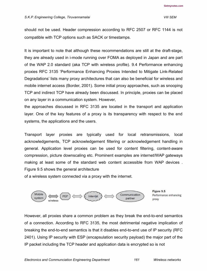
Getmynotes.com
S.K.P. Engineering College, Tiruvannamalai VIII SEM
should not be used. Header compression according to RFC 2507 or RFC 1144 is not
compatible with TCP options such as SACK or timestamps.
It is important to note that although these recommendations are still at the draft-stage,
they are already used in i-mode running over FOMA as deployed in Japan and are part
of the WAP 2.0 standard (aka TCP with wireless profile). 9.4 Performance enhancing
proxies RFC 3135 ‘Performance Enhancing Proxies Intended to Mitigate Link-Related
Degradations’ lists many proxy architectures that can also be beneficial for wireless and
mobile internet access (Border, 2001). Some initial proxy approaches, such as snooping
TCP and indirect TCP have already been discussed. In principle, proxies can be placed
on any layer in a communication system. However,
the approaches discussed in RFC 3135 are located in the transport and application
layer. One of the key features of a proxy is its transparency with respect to the end
systems, the applications and the users.
Transport layer proxies are typically used for local retransmissions, local
acknowledgements, TCP acknowledgement filtering or acknowledgement handling in
general. Application level proxies can be used for content filtering, content-aware
compression, picture downscaling etc. Prominent examples are internet/WAP gateways
making at least some of the standard web content accessible from WAP devices .
Figure 9.5 shows the general architecture
of a wireless system connected via a proxy with the internet.
However, all proxies share a common problem as they break the end-to-end semantics
of a connection. According to RFC 3135, the most detrimental negative implication of
breaking the end-to-end semantics is that it disables end-to-end use of IP security (RFC
2401). Using IP security with ESP (encapsulation security payload) the major part of the
IP packet including the TCP header and application data is encrypted so is not
Electronics and Communciation Engineering Department 161 Wireless networks

Getmynotes.com
S.K.P. Engineering College, Tiruvannamalai VIII SEM
accessible for a proxy. For any application one has to choose between using a
performance enhancing proxy and using IP security. This is a killer criterion in any
commercial environment as the only ‘solution’ would mean the integration of the proxy
into the security association between the end systems. Typically this is not feasible as
the proxy does not belong to the same organisation as the mobile node and the
corresponding node.
UNIT IV
PART A
1. What are the types of services provided by GPRS? (L-1,CO-4)
Two types of services are provided by GPRS:
Point-to-point (PTP)
Point-to-multipoint (PTM)
2. How packet data protocol helps in GPRS. (L-2,CO-4)
Within the GPRS networks, protocol data units ( PDUs) are encapsulated at theoriginating GSN and decapsulated at the destination GSN. In between the GSNs, IP isused as the backbone to transfer PDUs. This whole process is referred to as tunnellingin GPRS. The GGSN also maintains routing information used to tunnel the PDUs tothe SGSN that is currently serving the mobile station (MS). All GPRS user related datarequired by the SGSN to perform the routing and data transfer functionality is stored
Electronics and Communciation Engineering Department 162 Wireless networks
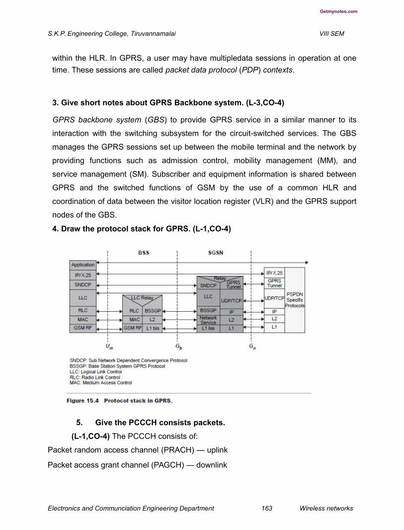
Getmynotes.com
S.K.P. Engineering College, Tiruvannamalai VIII SEM
within the HLR. In GPRS, a user may have multipledata sessions in operation at one
time. These sessions are called packet data protocol (PDP) contexts.
3. Give short notes about GPRS Backbone system. (L-3,CO-4)
GPRS backbone system (GBS) to provide GPRS service in a similar manner to its
interaction with the switching subsystem for the circuit-switched services. The GBS
manages the GPRS sessions set up between the mobile terminal and the network by
providing functions such as admission control, mobility management (MM), and
service management (SM). Subscriber and equipment information is shared between
GPRS and the switched functions of GSM by the use of a common HLR and
coordination of data between the visitor location register (VLR) and the GPRS support
nodes of the GBS.
4. Draw the protocol stack for GPRS. (L-1,CO-4)
5. Give the PCCCH consists packets.
(L-1,CO-4) The PCCCH consists of:
Packet random access channel (PRACH) — uplink
Packet access grant channel (PAGCH) — downlink
Electronics and Communciation Engineering Department 163 Wireless networks

Getmynotes.com
S.K.P. Engineering College, Tiruvannamalai VIII SEM
Packet notifi cation channel (PNCH) — downlink
On the other hand, the PTCH can either be:
Packet data traffi c channel (PDTCH)
Packet associated control channel (PACCH)
6. What are the cases handled by mobile terminated in data ? (L-1,CO-
4) Routing to the home GPRS network, and routing to a visited GPRS network. In
the fi rst case, a user sends a data packet to a mobile. The packet goes through
the local area network (LAN) via a router out on the GPRS context for the mobile.
If the mobile is in a GPRS idle state, the packet is rejected. If the mobile is in
standby or active mode, the GGSN routes the packet in an encapsulated format
to SGSN. In the second case, the home GPRS network sends the data packet
over the inter-operator backbone network to the visiting GPRS network. The
visiting GPRS network routes the packet to the appropriate SGSN.
7.What is meant byRadio Protocol Design? (L-1,CO-4)
The radio protocol strategy in EDGE is to reuse the protocols of GSM/GPRS whenever
possible, thus minimizing the need for new protocol implementation. EDGE enhances
both the GSM circuit-switched (HSCSD) and packet-switched (GPRS) mode operation.
EDGE includes one packet-switched and one circuit switched mode, EGPRS and ECSD
8.Give the significance about link adaption scheme. (L-3,CO-4)
A link adaptation scheme regularly estimates the link quality and subsequently selectsthe most appropriate modulation and coding scheme for the transmission to maximizethe user bit rate. The link adaptation scheme offers mechanisms for choosing the bestmodulation and coding scheme for the radio link.
9. Write the importance about Incremental redundancy. (H-1,CO-4)
Incremental redundancy scheme, the information is first sent with very little coding,
yielding a high bit rate if decoding is immediately successful. If decoding is not
Electronics and Communciation Engineering Department 164 Wireless networks

Getmynotes.com
S.K.P. Engineering College, Tiruvannamalai VIII SEM
successful, additional coded bits (redundancy) are sent until decoding succeeds. The
more coding that has to be sent, the lower the resulting bit rate and the higher the delay.
10. Give the short notes about ECSD. (L-1,CO-4)
Enhanced CSD (ECSD). In this case, the objective is to keep the existing GSMCS data protocols as intact as possible. In order to provide higher data rates, multislotsolutions as in ECSD are provided in EDGE. This has no impact on link or systemperformance. A data frame is interleaved over 22 frames as in GSM, and three new 8-PSK channel coding schemes are defined along with the four already existing for GSM.
11. Draw the diagram for IMT family. (L-1,CO-4)
Electronics and Communciation Engineering Department 165 Wireless networks

Getmynotes.com
S.K.P. Engineering College, Tiruvannamalai VIII SEM
12. Explain Iu, Iups, Iucs, Iur terms in detail. (L-1,CO-4)
The Iu is split functionally into two logical interfaces, Iups connecting the packetswitched domain to the access network and the Iucs connecting the circuit switcheddomain to the access network. The standards do not dictate that these are physicallyseparate, but the user plane for each is different and the control plane may be different.The Iur logically connects radio network controllers (RNCs) but could be physicallyrealized by a direct connection between RNCs or via the core network.
13. Write the services of physical layer. (L-2,CO-4)
The physical layer in UTRAN performs the following functions: Forward error correction,
bit-interleaving, and rate matching Signal measurements, Micro-diversity
distribution/combining and soft handoff execution, Multiplexing/mapping of services on
dedicated physical codes
14.What are the services provide by medium access control layer? (L-3,CO-4)
The medium access control sublayer is responsible for efficiently transferring data forboth real-time (CS) and non-real- time (PS) services to the physical layer. MAC offersservices to the radio link control (RLC) sublayer and higher layers. The MAC layerprovides data transfer services on logical channels
15. What does Mac responsible for? (H-1,CO-4)
MAC is responsible for
Selection of appropriate transport format (basically bit rate) within a predefined,set per
information unit delivered to the physical layer, Service multiplexing on random access
channel (RACH), forward access
channel (FACH), and dedicated channel (DCH)
Priority handling between data flow of a user as well as between data flows from several
users - Access control on RACH and FACH, Contention resolution on RACH
16. What are the types of DPCH? (H-2,CO-4)
Electronics and Communciation Engineering Department 166 Wireless networks
Getmynotes.com
S.K.P. Engineering College, Tiruvannamalai VIII SEM
There are two types of DPCH: (1) dedicated physical data channel (DPDCH) to carry
user data and signaling information generated at layer 2 (there may be none, one, or
several DPDCHs); and (2) dedicated physical control channel (DPCCH) to carry control
information generated at layer 1 (pilot bits, transmit power control (TPC) commands,
feedback information (FBI) commands, and optional transport format combination
indicator (TFCI))
PART B
1.Explain the GSM Evolution for Data rate for WLAN. (L-1,CO-4)
From a radio access perspective, adding 3G capabilities to 2G systems mainly means
supporting higher data rates. Possible scenarios depend on spectrum availability for the
network service provider. Depending on the spectrum situation, two different migration
paths can be supported:
Reframing of existing spectrum bands New or modifi ed spectrum bands. Two
3G radio access schemes are identifi ed to support the different spectrum
scenarios:
1. Enhanced data rates for GSM evolution (EDGE) with high-level modulation in a
200 kHz TDMA channel is based on plug-in transceiver equipment, thereby
allowing the migration of existing bands in small spectrum segments.
2. Universal mobile telecommunications services (UMTS) is a new radio access
network based on 5 MHz WCDMA and optimized for efficient support of 3G
services. UMTS can be used in both new and existing spectra From a network
point of view, 3G capabilities implies the addition of packet switched (PS)
services, Internet access, and IP connectivity. With this approach, the existing
mobile networks reuse the elements of mobility support, user authentication/
service handling, and circuit switched (CS) services. With packet switched
services, IP connectivity can then be added to provide a mobile multimedia core
network by evolving the existing mobile network.
GSM is moving to develop enhanced cutting-edge, customer-focused solutions to meet
the challenges of the new millennium and 3G mobile services [29]. When GSM was fi
rst introduced, no one could have predicted the dramatic growth of the Internet and the
rising demand for multimedia services. These developments have brought about new
Electronics and Communciation Engineering Department 167 Wireless networks

Getmynotes.com
S.K.P. Engineering College, Tiruvannamalai VIII SEM
challenges to the world of GSM. For GSM operators, the emphasis is now rapidly
changing from that of instigating and driving the development of technology to
fundamentally enabling mobile data transmission to that of improving speed, quality,
simplicity, coverage, and reliability in terms of tools and services that will boost mass
market take-up.
Users are increasingly looking to gain access to information and services wherever they
are and whenever they want. GSM should provide that connectivity. Internet access,
web browsing and the whole range of mobile multimedia capability are the major drivers
for development of higher data speed technologies. Current data traffi c on most GSM
networks is modest, less than 5% of total GSM traffi c. But with the new initiatives
coming to fruition during the course of the next two to three years, exponential growth in
data traffi c is forecast. The use of messaging-based applications may reach up to about
90% by the year 2008. GSM data transmission using high-speed circuit switched data
(HSCSD) and GPRS may reach a penetration of about 80% by 2008 [1].
GSM operators have two nonexclusive options for evolving their networks to 3G
wideband multimedia operation: (1) using GPRS and EDGE in the existing radio
spectrum, and in small amounts of the new spectrum; or (2) using WCDMA in the new 2
GHz bands, or in large amounts of the existing spectrum. Both approaches offer a high
degree of investment fl exibility because roll-out can proceed in line with market
demand with the extensive reuse of existing network equipment and radio sites.
In the new 2 GHz bands, 3G capabilities are delivered using a new wideband radio
interface that offers much higher user data rates than are available today — 384 kbps in
the wide area and up to 2 Mbps in the local area. Of equal importance for such services
is the high-speed packet switching provided by GPRS and its connection to public and
private IP networks. GSM and digital (D)AMPS (IS-136) operators can use existing
radio bands to deliver some of the 3G services, even without the new wideband
spectrum by evolving current networks and deploying GPRS and EDGE technologies.
In the early years of 3G service deployment, a large proportion of wireless traffi c will
still be voice-only and low-rate data. So whatever the ultimate capabilities of 3G
networks, effi cient and profi table ways of delivering more basic wireless
Electronics and Communciation Engineering Department 168 Wireless networks
Getmynotes.com
S.K.P. Engineering College, Tiruvannamalai VIII SEM
services are still needed. The signifi cance of EDGE for today’s GSM operators is that it
increases data rates up to 384 kbps and potentially even higher in a good quality radio
environment using current GSM spectrum and carrier structures more effi ciently. EDGE
is both a complement and an alternative to new WCDMA coverage. EDGE also has the
effect of unifying the GSM, D-AMPS and WCDMA services through the use of dual-
mode terminals.
2.How the High Speed Circuit Switched Data is performed in wireless networking
techniques.. (L-2,CO-4)
High-speed circuit switched data (HSCSD) [1,4,5] is a feature that enables the co-
allocation of multiple full rate traffi c channels (TCH/F) of GSM into an HSCSD confi
guration. The aim of HSCSD is to provide a mixture of services with different air
interface user rates by a single physical layer structure. The available capacity of an
HSCSD confi guration is several times the capacity of a TCH/F, leading to a signifi cant
enhancement in air interface data transfer capability. Ushering faster data rates into the
mainstream is the new speed of 14.4 kbps per time slot and HSCSD protocols that
approach wireline access rates of up to 57.6 kbps by using multiple 14.4 kbps time
slots. The increase from the current baseline of 9.6 kbps to 14.4 kbps is due to a
nominal reduction in the error-correction overhead of the GSM radio link protocol (RLP),
allowing the use of a higher data rate.
For operators, migration to HSCSD brings data into the mainstream, enabled in many
cases by relatively standard software upgrades to base station (BS) and mobile
switching center (MSC) equipment. Flexible air interface resource allocation allows the
network to dynamically assign resources related to the air interface usage according to
the network operator’s strategy, and the end-user’s request for a change in the air
interface resource allocation based on data transfer needs. The provision of the
asymmetric air interface connection allows simple mobile equipment to receive data at
higher rates than otherwise would be possible with a symmetric connection.
For end-users, HSCSD enables the roll-out of mainstream high-end segment services
that enable faster web browsing, fi le downloads, mobile video-conference and
navigation, vertical applications, telematics, and bandwidth-secure mobile local area
network (LAN) access. Value-added service providers will also be able to offer
Electronics and Communciation Engineering Department 169 Wireless networks
Getmynotes.com
S.K.P. Engineering College, Tiruvannamalai VIII SEM
guaranteed quality of service and cost-effi cient mass-market applications, such as
direct IP where users make circuit-switched data calls straight into a GSM network
router connected to the Internet. To the end-user, the value-added service
provider or the operator is equivalent to an Internet service provider that offers a fast,
secure dial-up Internet protocol service at cheaper mobile-to-mobile rates. HSCSD is
provided within the existing mobility management. Roaming is also possible. The
throughput for an HSCSD connection remains constant for the duration of the call,
except for interruption of transmission during handoff. The handoff is simultaneous for
all time slots making up an HSCSD connection. Endusers wanting to use HSCSD have
to subscribe to general bearer services. Supplementary services applicable to general
bearer services can be used simultaneously with HSCSD.Firmware on most current
GSM PC cards needs to be upgraded. The reduced RLP layer also means that a
stronger signal strength is necessary. Multiple time slot usage is probably only effi
ciently available in off-peak times, increasing overall off-peak idle capacity usage.
HSCSD is not a very feasible solution for bursty data applications.
3. Briefly explain about the techniques about General Packet Radio Service.
(L-1,CO-4)
The general packet radio service (GPRS) [6,7] enhances GSM data services signifi
cantly by providing end-to-end packet switched data connections. This is particularly effi
cient in Internet/intranet traffi c, where short bursts of intense data communications are
actively interspersed with relatively long periods of inactivity. Because there is no real
end-to-end connection to be established, setting up a GPRS call is almost
instantaneous and users can be continuously on-line. Users have the additional benefi
ts of paying for the actual data transmitted, rather than for connection time. Because
GPRS does not require any dedicated end-to-end connection, it only uses network
resources and bandwidth when data is actually being transmitted. This means that a
given amount of radio bandwidth can be shared efficiently among many users
simultaneously.
The next phase in the high-speed road map is the evolution of current short message
service (SMS), such as smart messaging and unstructured supplementary service data
(USSD), toward the new GPRS, a packet data service using TCP/IP and X.25 to offer
Electronics and Communciation Engineering Department 170 Wireless networks
Getmynotes.com
S.K.P. Engineering College, Tiruvannamalai VIII SEM
speeds up to 115 kbps. GPRS has been standardized to optimally support a wide range
of applications ranging from very frequent transmissions of medium to large data
volume. Services of GPRS have been developed to reduce connection set-up time and
allow an optimum usage of radio resources. GPRS provides a packet data service for
GSM where time slots on the air interface can be assigned to GPRS over which packet
data from several mobile stations is multiplexed.
A similar evolution strategy, also adopting GPRS, has been developed for DAMPS (IS-
136). For operators planning to offer wideband multimedia services, the move to GPRS
packet-based data bearer service is significant; it is a relatively small step compared to
building a totally new 3G IMT-2000 network. Use of the GPRS network architecture for
IS-136_ packet data service enables data subscription roaming with GSM networks
around the globe that support GPRS and
its evolution. The IS-136_ packet data service standard is known as GPRS-136. GPRS-
136 provides the same capabilities as GSM GPRS. The user can access either X.25 or
an IP-based data network. only to expand the wireless data market in preparation for
the introduction of 3G services, but also a platform on which to build IMT-2000
frequencies should they acquire them.
The implementation of GPRS has a limited impact on the GSM core network .
It simply requires the addition of new packet data switching and gateway nodes, and an
upgrade to existing nodes to provide a routing path for packet data between the
wireless terminal and a gateway node. The gateway node provides interworking with
external packet data networks for access to the Internet, intranet, and databases.
A GPRS architecture for GSM is shown in Figure 15.2 and network element interfaces
in Figure 15.3. GPRS supports all widely used data communications
Electronics and Communciation Engineering Department 171 Wireless networks

Getmynotes.com
S.K.P. Engineering College, Tiruvannamalai VIII SEM
protocols, including IP, so it is possible to connect with any data source from anywhere
in the world using a GPRS mobile terminal. GPRS supports applications ranging from
Electronics and Communciation Engineering Department 172 Wireless networks
Getmynotes.com
S.K.P. Engineering College, Tiruvannamalai VIII SEM
low-speed short messages to high-speed corporate LAN communications. However,
one of the key benefi ts of GPRS — that it is connected through the existing GSM air
interface modulation scheme — is also a limitation, restricting its potential for delivering
higher data rates than 115 kbps. To build even higher rate data capabilities into GSM, a
new modulation scheme is needed.
GPRS can be implemented in the existing GSM systems. Changes are required in an
existing GSM network to introduce GPRS. The base station subsystem (BSS) consists
of a base station controller (BSC) and packet control unit (PCU). The PCU supports all
GPRS protocols for communication over the air interface. Its function is to set up,
supervise, and disconnect packet switched calls. The packet control unit supports cell
change, radio resource confi guration, and channel assignment. The base station
transceiver (BTS) is a relay station without protocol functions. It performs modulation
and demodulation. The GPRS standard introduces two new nodes, the serving GPRS
support node (SGSN) and the gateway GPRS support node (GGSN). The home
location register (HLR) is enhanced with GPRS subscriber data and routing information.
Two types of services are provided by GPRS:
Point-to-point (PTP)
Point-to-multipoint (PTM)
Independent packet routing and transfer within the public land mobile network (PLMN)
is supported by a new logical network node called the GPRS support node (GSN). The
GGSN acts as a logical interface to external packet data networks. Within the GPRS
networks, protocol data units (PDUs) are encapsulated at the originating GSN and
decapsulated at the destination GSN. In between the GSNs, IP is used as the backbone
to transfer PDUs. This whole process is referred to as tunnelling in GPRS. The GGSN
also maintains routing information used to tunnel the PDUs to the SGSN that is
currently serving the mobile station (MS). All GPRS user related data required by the
SGSN to perform the routing and data transfer functionality is stored within the HLR. In
GPRS, a user may have multipledata sessions in operation at one time. These sessions
are called packet data protocol (PDP) contexts. The number of PDP contexts that are
open for a user is only limited by the user’s subscription and any operational constraints
of the network. The main goal of the GPRS-136 architecture is to integrate IS-136 and
Electronics and Communciation Engineering Department 173 Wireless networks

Getmynotes.com
S.K.P. Engineering College, Tiruvannamalai VIII SEM
GSM GPRS as much as possible with minimum changes to both technologies. In order
to provide subscription roaming between GPRS-136 and GSM GPRS networks, a
separate functional GSM GPRS HLR is incorporated into the architecture in addition to
the IS-41 HLR. The European Telecommunication Standards Institute (ETSI) has specifi
ed GPRS as an overlay to the existing GSM network to provide packet data services.In
order to operate a GPRS over a GSM network, new functionality has been introduced
into existing GSM network elements (NEs) and new NEs are integrated into the existing
service provider’s GSM network.
The BSS of GSM is upgraded to support GPRS over the air interface. The BSS works
with the GPRS backbone system (GBS) to provide GPRS service in a similar manner to
its interaction with the switching subsystem for the circuit-switched services. The GBS
manages the GPRS sessions set up between the mobile terminal and the network by
providing functions such as admission control, mobility management (MM), and service
management (SM). Subscriber and equipment information is shared between GPRS
and the switched functions of GSM by the use
of a common HLR and coordination of data between the visitor location register (VLR)
and the GPRS support nodes of the GBS. The GBS is composed of two new NEs — the
SGSN and the GGSN. The SGSN serves the mobile and performs security and access
control functions. The SGSN is connected to the BSS via frame-relay. The SGSN prov
packet routing, mobility management, authentication, and ciphering to and from all
GPRS subscribers located in the SGSN service area. A GPRS subscriber may be
served by any SGSN in the network, depending on location. The traffi c is routed from
the SGSN to the BSC and to the mobile terminal via a BTS. At GPRS attach, the SGSN
establishes a mobility management context containing information about mobility and
security for the mobile. At PDP context activation, the SGSN establishes a PDP context
which is used for routing purposes with the GGSN that the GPRS subscriber uses. The
SGSN may send in some cases location information to the MSC/VLR and receive
paging requests. The GGSN provides the gateway to the external IP network, handling
security and accounting functions as well as the dynamic allocation of IP addresses.The
GGSN contains routing information for the attached GPRS users. The routing
information is used to tunnel PDUs to the mobile’s current point of attachment,
Electronics and Communciation Engineering Department 174 Wireless networks

Getmynotes.com
S.K.P. Engineering College, Tiruvannamalai VIII SEM
SGSN. The GGSN may be connected with the HLR via optional interface Gc. The
GGSN is the fi rst point of public data network (PDN) interconnection with a GSM PLMN
supporting GPRS. From the external IP network’s point of view, the GGSN is a host that
owns all IP addresses of all subscribers served by the GPRS network.
The PTM-SC handles PTM traffic between the GPRS backbone and the HLR. The
nodes are connected by an IP backbone network. The SGSN and GGSN functions may
be combined in the same physical node or separated — even residing in different
mobile networks.
A special interface (Gs) is provided between MSC/VLR and SGSN to coordinate
signaling for mobile terminals that can handle both circuit-switched and packet-switched
data.
The HLR contains GPRS subscription data and routing information, and can be
accessible from the SGSN. For the roaming mobiles, the HLR may reside in a different
PLMN than the current SGSN. The HLR also maps each subscriber to one or more
GGSNs.
The objective of the GPRS design is to maximize the use of existing GSM infrastructure
while minimizing the changes required within GSM. The GSN contains most of the
necessary capabilities to support packet transmission over GSM. The critical part in the
GPRS network is the mobile to GSN (MS-SGSN) link which includes the MS-BTS, BTS-
BSC, BSC-SGSN, and the SGSN-GGSN link. In particular, the Um interface including
the radio channel is the bottleneck of the GPRS network due to the spectrum and
channel speed/quality limitations. Since multiple traffi c types of varying priorities are
supported by the GPRS network, the quality of service criteria as well as resource
management is required for performance evaluation.
The BSC will require new capabilities for controlling the packet channels, new hardware
in the form of a packet control unit, and new software for GPRS mobility management
and paging. The BSC also has a new traffi c and signaling interface from the SGSN.
The BTS has new protocols supporting packet data for the air interface, together with
new slot and channel resource allocation functions. The utilization of resources is
optimized through dynamic sharing between the two traffi c types handled by the BSC.
Electronics and Communciation Engineering Department 175 Wireless networks
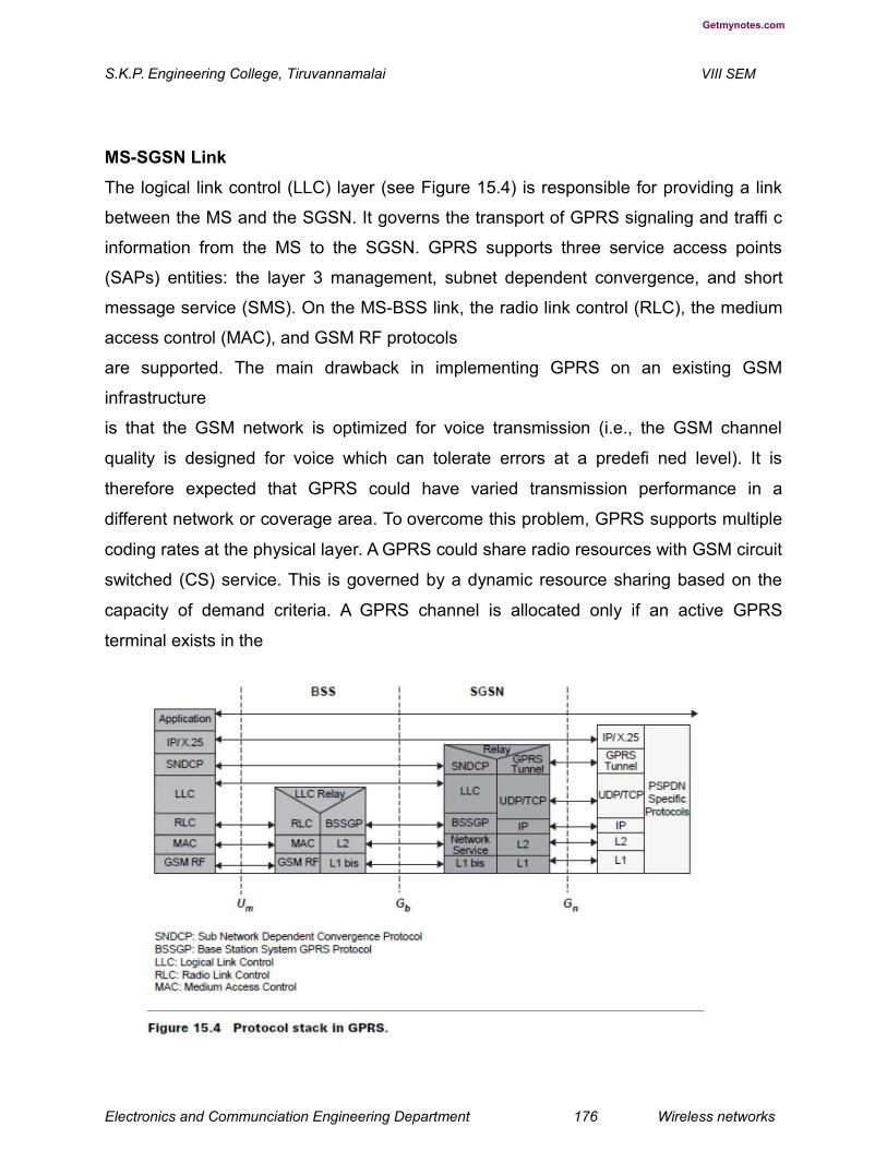
Getmynotes.com
S.K.P. Engineering College, Tiruvannamalai VIII SEM
MS-SGSN Link
The logical link control (LLC) layer (see Figure 15.4) is responsible for providing a link
between the MS and the SGSN. It governs the transport of GPRS signaling and traffi c
information from the MS to the SGSN. GPRS supports three service access points
(SAPs) entities: the layer 3 management, subnet dependent convergence, and short
message service (SMS). On the MS-BSS link, the radio link control (RLC), the medium
access control (MAC), and GSM RF protocols
are supported. The main drawback in implementing GPRS on an existing GSM
infrastructure
is that the GSM network is optimized for voice transmission (i.e., the GSM channel
quality is designed for voice which can tolerate errors at a predefi ned level). It is
therefore expected that GPRS could have varied transmission performance in a
different network or coverage area. To overcome this problem, GPRS supports multiple
coding rates at the physical layer. A GPRS could share radio resources with GSM circuit
switched (CS) service. This is governed by a dynamic resource sharing based on the
capacity of demand criteria. A GPRS channel is allocated only if an active GPRS
terminal exists in the
Electronics and Communciation Engineering Department 176 Wireless networks
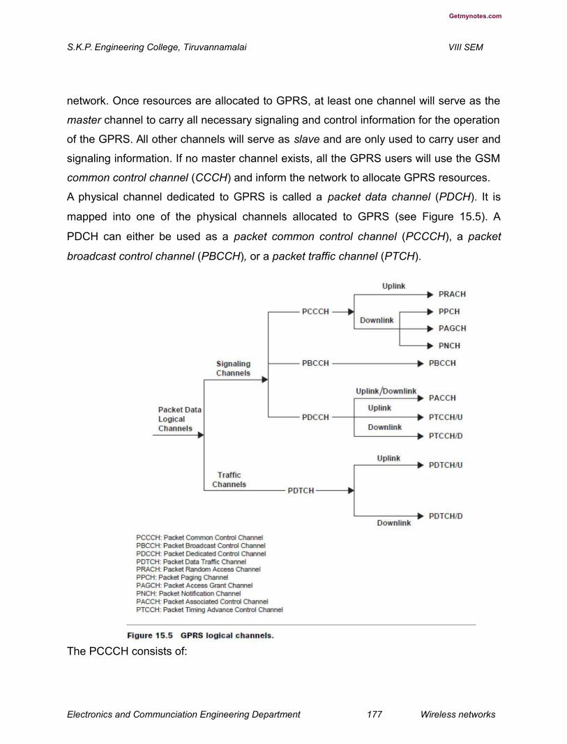
Getmynotes.com
S.K.P. Engineering College, Tiruvannamalai VIII SEM
network. Once resources are allocated to GPRS, at least one channel will serve as the
master channel to carry all necessary signaling and control information for the operation
of the GPRS. All other channels will serve as slave and are only used to carry user and
signaling information. If no master channel exists, all the GPRS users will use the GSM
common control channel (CCCH) and inform the network to allocate GPRS resources.
A physical channel dedicated to GPRS is called a packet data channel (PDCH). It is
mapped into one of the physical channels allocated to GPRS (see Figure 15.5). A
PDCH can either be used as a packet common control channel (PCCCH), a packet
broadcast control channel (PBCCH), or a packet traffic channel (PTCH).
The PCCCH consists of:
Electronics and Communciation Engineering Department 177 Wireless networks

Getmynotes.com
S.K.P. Engineering College, Tiruvannamalai VIII SEM
Packet random access channel (PRACH) — uplink
Packet access grant channel (PAGCH) — downlink
Packet notifi cation channel (PNCH) — downlink
On the other hand, the PTCH can either be:
Packet data traffi c channel (PDTCH)
Packet associated control channel (PACCH)
The arrangement of GPRS logical channels for given traffi c characteristics also
requires the combination of PCCCHs and PTCHs. Fundamental questions such as how
many PDTCHs can be supported by a single PCCCH is needed in dimensioning GPRS.
RLC/MAC Layer
The multiframe structure of the PDCH in which GPRS RLC messages are transmitted is
composed of 52 TDMA frames organized into RLC blocks of four bursts resulting in 12
blocks per multiframe plus four idle frames located in the 13th, 26th, 39th, and 52nd
positions (see Figure 15.6). B0 consists of frames 1, 2, 3 and 4, B1 consists of frames
5, 6, 7, and 8 and so on. It is important that the mapping of logical channels onto the
radio blocks is done by means of an ordered set of blocks (B0, B6, B9, B1, B7, B4, B10,
B2, B8, B5, B11). The advantage of ordering the blocks is mainly to spread the locations
of the control channels in each time slot reducing the average waiting time for the users
to transmit signaling packets. It also provides an interleaving of the GPRS multiframe.
GPRS uses a reservation protocol at the MAC layer. Users that have packets ready to
send request a channel via the PRACHs. The random access burst consists of only one
TDMA frame with duration enough to transmit an 11-bit signaling message. Only the
PDCHs carrying PCCCHs contain PRACHs. The blocks used as PRACHs are indicated
by an uplink state fl ag (USF _ free) by the downlink pair channel.
Electronics and Communciation Engineering Department 178 Wireless networks
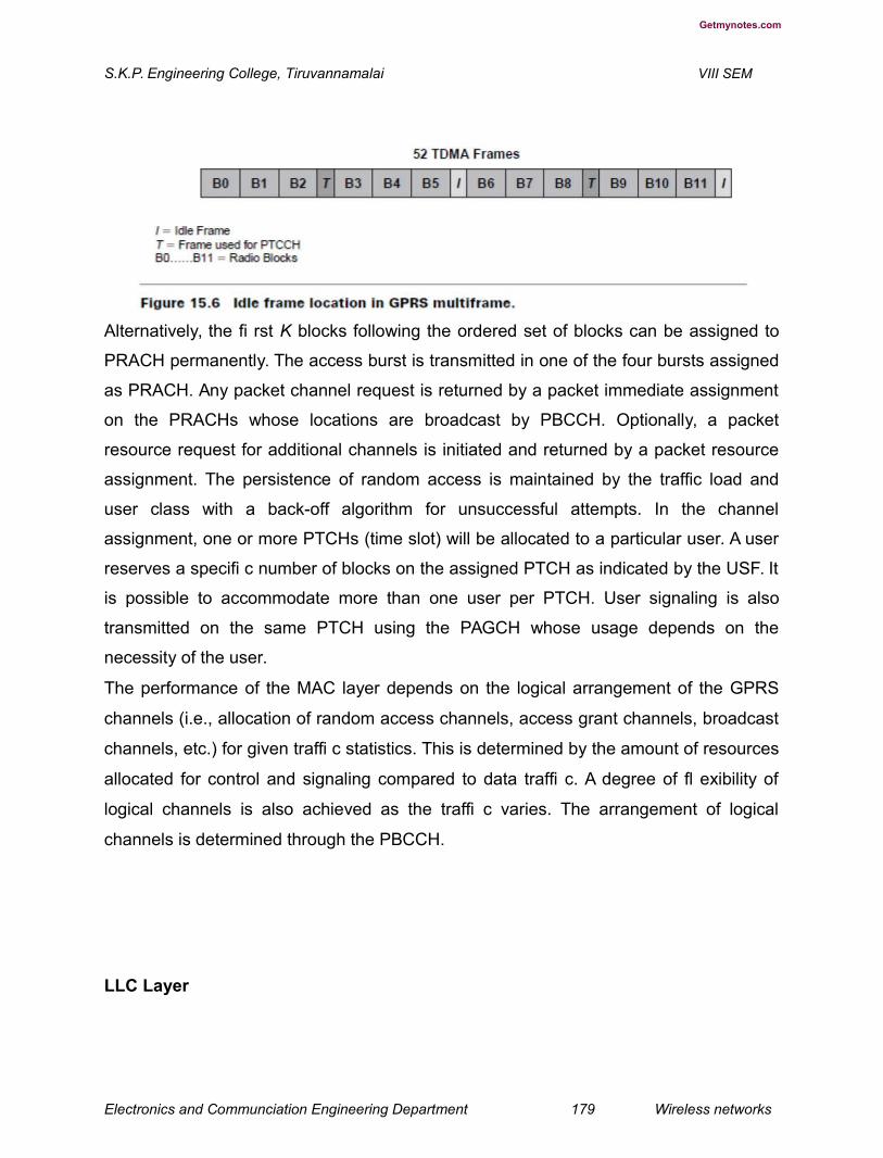
Getmynotes.com
S.K.P. Engineering College, Tiruvannamalai VIII SEM
Alternatively, the fi rst K blocks following the ordered set of blocks can be assigned to
PRACH permanently. The access burst is transmitted in one of the four bursts assigned
as PRACH. Any packet channel request is returned by a packet immediate assignment
on the PRACHs whose locations are broadcast by PBCCH. Optionally, a packet
resource request for additional channels is initiated and returned by a packet resource
assignment. The persistence of random access is maintained by the traffic load and
user class with a back-off algorithm for unsuccessful attempts. In the channel
assignment, one or more PTCHs (time slot) will be allocated to a particular user. A user
reserves a specifi c number of blocks on the assigned PTCH as indicated by the USF. It
is possible to accommodate more than one user per PTCH. User signaling is also
transmitted on the same PTCH using the PAGCH whose usage depends on the
necessity of the user.
The performance of the MAC layer depends on the logical arrangement of the GPRS
channels (i.e., allocation of random access channels, access grant channels, broadcast
channels, etc.) for given traffi c statistics. This is determined by the amount of resources
allocated for control and signaling compared to data traffi c. A degree of fl exibility of
logical channels is also achieved as the traffi c varies. The arrangement of logical
channels is determined through the PBCCH.
LLC Layer
Electronics and Communciation Engineering Department 179 Wireless networks
Getmynotes.com
S.K.P. Engineering College, Tiruvannamalai VIII SEM
The LLC layer is responsible for providing a reliable link between the mobile and the
SGSN. It is based on the LAPD (link access protocol D) protocol. It is designed to
support variable length transmission in a PTP or PTM topology. It includes the layer
function such as sequence control, fl ow control, error detection, ciphering, and recovery
as well as the provision of one or more logical link connections between two layer 3
entities. A logical link is identifi ed by a DLCI (data link control identity) which consists of
a service access point identity (SAPI) and terminal equipment identity (TEI) mapped on
the LLC frame format. Depending on the status of the logical link, it supports an
unacknowledged or an acknowledged information transfer. The former does not support
error recovery mechanisms. The acknowledged information transfer supports error and
flow control. This operation only applies to point-to-point operations. The LLC frame
consists of an address field (1 or 5 octets), control fi eld (2 or 6 octets), a length
indicator fi eld (2 octets maximum), information fi elds (1500 octets maximum), and a
frame check sequence of 3 octets. Four types of control fi eld formats are allowed
including the supervisory functions (S format), the control functions (U), and
acknowledged and unacknowledged information transfer (I and UI). In the performance
evaluation, the objective is to determine delay during the exchange of commands and
responses involved in various operations supported by the LLC in relation to the transfer
of an LLC PDU. The LLC commands and responses are exchanged between two layer
3 entities in conjunction with a service primitive invoked by the mobile or the SGSN.
Data Packet Routing in the GPRS Network
The following discusses data packet routing for the mobile originated and mobile
terminated data call scenarios. In mobile originated data routing, the mobile gets an IP
packet from an application and requests a channel reservation. The mobile transmits
data in the reserved time slots. The packet switched public data network (PSPDN) PDU
is encapsulated into a sub-network dependent convergence protocol (SNDCP) unit that
is sent via LLC protocol over the air interface to the SGSN currently serving the mobile
(see Figure 15.7).
For mobile terminated data routing (see Figure 15.7), we have two cases:
Electronics and Communciation Engineering Department 180 Wireless networks

Getmynotes.com
S.K.P. Engineering College, Tiruvannamalai VIII SEM
routing to the home GPRS network, and routing to a visited GPRS network. In the fi rst
case, a user sends a data packet to a mobile. The packet goes through the local area
network (LAN) via a router out on the GPRS context for the mobile. If the mobile is in a
GPRS idle state, the packet is rejected. If the mobile is in standby or active mode, the
GGSN routes the packet in an encapsulated format to SGSN. In the second case, the
home GPRS network sends the data packet over the inter-operator backbone network
to the visiting GPRS network. The visiting GPRS network routes the packet to the
appropriate SGSN.
The PTP and PTM applications of GPRS are listed below:
Point-to-point
Messaging (e.g., e-mail)
Remote access to corporate networks
Access to the Internet
Credit card validation (point-of-sales)
Utility meter readings
Road toll applications
Automatic train control
Point-to-multipoint
PTM-multicast (send to all)
News
Electronics and Communciation Engineering Department 181 Wireless networks
Getmynotes.com
S.K.P. Engineering College, Tiruvannamalai VIII SEM
Traffi c information
Weather forecasts
Financial updates
PTM-group call (send to some)
Taxi fl eet management
Conferencing
GPRS provides a service for bursty and bulky data transfer, radio resources on
demand, shared use of physical radio resources, existing GSM functionality, mobile
applications for a mass application market, volume dependent charging, and integrated
services, operation and management.
4.Explain the Enhanced Data Rates for GSM Enhancement in networking. (L-1,CO-
4)
The enhanced data rates for GSM enhancements (EDGE) [8] provides an evolutionary
path from existing 2G systems (GSM, IS-136, PDC) to deliver some 3G services in
existing spectrum bands. The advantages of EDGE include fast availability, reuse of
existing GSM, IS-136 and PDC infrastructure, as well as support for the gradual
introduction of 3G capabilities.
EDGE is primarily a radio interface improvement, but it can also be viewed as a system
concept that allows GSM, IS-136, and PDC networks to offer a set of new services.
EDGE has been designed to improve S/I by using link quality control. Link quality
control adapts the protection of the data to the channel quality so that for all channel
qualities an optimal bit rate is achieved.
EDGE can be seen as a generic air interface for effi ciently providing high bit rates,
facilitating an evolution of existing 2G systems toward 3G systems. The EDGE air
interface is designed to facilitate higher bit rates than those currently achievable in
existing 2G systems. The modulation scheme based on 8-PSK is used to increase the
gross bit rate. GMSK modulation as defi ned in GSM is also part of the EDGE system.
The symbol rate is 271 ksps for both GMSK and 8-PSK,
leading to gross bit rates per time slot of 22.8 kbps and 69.2 kbps, respectively.
The 8-PSK pulse shape is linearized by GMSK to allow 8-PSK to fi t into the GSM
Electronics and Communciation Engineering Department 182 Wireless networks

Getmynotes.com
S.K.P. Engineering College, Tiruvannamalai VIII SEM
spectrum mask. The 8-PSK burst format is similar to GSM (see Figure 15.8). EDGE
reuses the GSM carrier bandwidth and time slot structure. EDGE (also known as the
2.5G system) has been designed to enhance user bandwidth through GPRS. This is
achieved through the use of higher-level modulation schemes. Although EDGE reuses
the GSM carrier bandwidth and time slot structure, the technique is by no means
restricted to GSM systems; it can be used as a generic air interface for effi cient
provision of higher bit rates in other TDMA systems. In the Universal Wireless
Communications Consortium (UWCC) the 136 high speed (136 HS) radio transmission
technology (RTT) radio interface was proposed as a means to satisfy the requirements
for an IMT-2000 RTT. EDGE was adopted by UWCC in 1998 as the outdoor component
of 136 HS to
provide 384 kbps data service.
The standardization effort for EDGE has two phases. In the fi rst phase of EDGE the
emphasis has been placed on enhanced GPRS (EGPRS) and enhanced CSD (ECSD).
The second phase is defi ned with improvements for multimedia and real-time services.
In order to achieve a higher gross rate, new modulation scheme, quaternary offset
quadrature amplitude modulation (QOQAM) has been proposed for EDGE, since it can
provide higher data rates and good spectral effi ciency. An offset modulation scheme is
proposed because it gives smaller amplitude variation than 16-QAM, which can be
benefi cial when using nonlinear amplifi ers. EDGE co-exists with GSM in an existing
frequency plan and provides link adaptation (modulation and coding are adapted for
channel conditions).
Radio Protocol Design
The radio protocol strategy in EDGE is to reuse the protocols of GSM/GPRS whenever
possible, thus minimizing the need for new protocol implementation. EDGE enhances
both the GSM circuit-switched (HSCSD) and packet-switched (GPRS) mode operation.
Electronics and Communciation Engineering Department 183 Wireless networks
Getmynotes.com
S.K.P. Engineering College, Tiruvannamalai VIII SEM
EDGE includes one packet-switched and one circuit switched mode, EGPRS and
ECSD, respectively.
Enhanced GPRS (EGPRS). The EDGE radio link control (RLC) protocol is somewhat
different from the corresponding GPRS protocol. The main changes are related to
improvements in link quality control scheme. A link adaptation scheme regularly
estimates the link quality and subsequently selects the most appropriate modulation and
coding scheme for the transmission to maximize the user bit rate. The link adaptation
scheme offers mechanisms for choosing the best modulation and coding scheme for the
radio link. In GPRS only the coding schemes can be changed between two consecutive
link layer control (LLC) frames. In the EGPRS even the modulation can be changed.
Different coding and modulation schemes enable adjustment for the
robustness of the transmission according to the environment. Another way to handle link
quality variations is incremental redundancy. In this scheme, information is fi rst sent
with very little coding, yielding a high bit rate if decoding is immediately successful. If
decoding is not successful, additional coded bits (redundancy) are sent until decoding
succeeds. The more coding that has to be sent, the lower the resulting bit rate and the
higher the delay. EGPRS supports combined link adaptation and incremental
redundancy schemes. In this case, the initial code rate of the incremental redundancy
scheme is based on measurements of the link quality. Benefi ts of this approach are the
robustness and high throughput of the incremental redundancy operation in combination
with lower delays and lower memory requirements enabled by the adaptive initial code
rate. In EGPRS the different initial code rates are obtained by puncturing a different
number of bits from a common convolutional code R _ 1/3. The resulting coding
schemes are given in Table 15.1. Incremental redundancy operation is enabled by
puncturing a different set of bits each time a block is retransmitted, whereby the code
rate is gradually decreased toward 1/3 for every new transmission of the block. The
selection of the initial modulation and code rate is based on regular measurements of
link quality.
Electronics and Communciation Engineering Department 184 Wireless networks

Getmynotes.com
S.K.P. Engineering College, Tiruvannamalai VIII SEM
Actual performance of modulation and coding scheme together with channel
characteristics form the basis for link adaptation. Channel characteristics are needed to
estimate the effects of a switch to another modulation and coding combination and
include an estimated S/I ratio, but also time dispersion and fading characteristics (that
affect the effi ciency of interleaving).
EGPRS offers eight additional coding schemes. The EGPRS user has eight modulation
and coding schemes available compared to four for GPRS. Besides changes in the
physical layer, modifi cations in the protocol structure are also needed. The lower layers
of the user data plane designed for GPRS are the physical, RLC MAC, and LLC layers.
With EDGE functionality, the LLC layer will not require any modifi cations; however, the
RLC/MAC layer has to be modifi ed to accommodate features for effi cient multiplexing
and link adaptation procedures to support the basically new physical layer in the EDGE.
In the case of GSM, EDGE with the existing GSM radio bands offers wireless
multimedia, IP-based applications at the rate of 384 kbps with a bit-rate of 48 kbps per
time slot and, under good radio conditions, up to 69.2 kbps per time slot.
Enhanced CSD (ECSD). In this case, the objective is to keep the existing GSM CS
data protocols as intact as possible. In order to provide higher data rates, multislot
Electronics and Communciation Engineering Department 185 Wireless networks
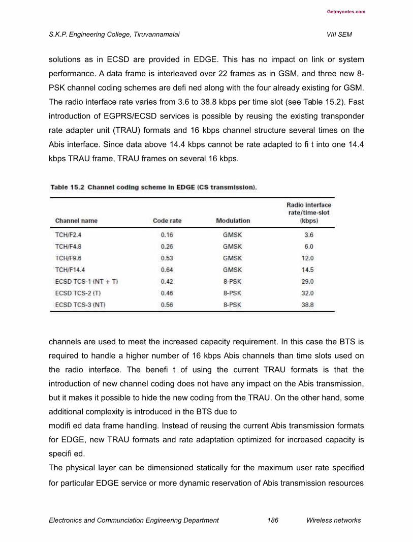
Getmynotes.com
S.K.P. Engineering College, Tiruvannamalai VIII SEM
solutions as in ECSD are provided in EDGE. This has no impact on link or system
performance. A data frame is interleaved over 22 frames as in GSM, and three new 8-
PSK channel coding schemes are defi ned along with the four already existing for GSM.
The radio interface rate varies from 3.6 to 38.8 kbps per time slot (see Table 15.2). Fast
introduction of EGPRS/ECSD services is possible by reusing the existing transponder
rate adapter unit (TRAU) formats and 16 kbps channel structure several times on the
Abis interface. Since data above 14.4 kbps cannot be rate adapted to fi t into one 14.4
kbps TRAU frame, TRAU frames on several 16 kbps.
channels are used to meet the increased capacity requirement. In this case the BTS is
required to handle a higher number of 16 kbps Abis channels than time slots used on
the radio interface. The benefi t of using the current TRAU formats is that the
introduction of new channel coding does not have any impact on the Abis transmission,
but it makes it possible to hide the new coding from the TRAU. On the other hand, some
additional complexity is introduced in the BTS due to
modifi ed data frame handling. Instead of reusing the current Abis transmission formats
for EDGE, new TRAU formats and rate adaptation optimized for increased capacity is
specifi ed.
The physical layer can be dimensioned statically for the maximum user rate specified
for particular EDGE service or more dynamic reservation of Abis transmission resources
Electronics and Communciation Engineering Department 186 Wireless networks
Getmynotes.com
S.K.P. Engineering College, Tiruvannamalai VIII SEM
can be applied. The Abis resources can even be released and reserved dynamically
during the call, if the link adaptation is applied.The channel coding schemes defi ned for
EDGE in PS transmission are listed in Table 15.1 and in CS transmission in Table 15.2.
Services Offered by EDGE
PS Services. The GPRS architecture provides IP connectivity from the mobile station to
an external fi xed IP network. For each service, a QoS profi le is defi ned.The QoS
parameters include priority, reliability, delay, and maximum and mean bit rate. A specifi
ed combination of these parameters defi nes a service, and different services can be
selected to suit the needs of different applications.
CS Services. The current GSM standard supports both transparent (T) and
nontransparent (NT) services. Eight transparent services are defi ned, offering constant
bit rates in the range of 9.6 to 64 kbps.
A nontransparent service uses RLP to ensure virtually error-free data delivery.For this
case, there are eight services offering maximum user bit rates from 4.8 to 57.6 kbps.
The actual user bit rate may vary according to channel quality and the resulting rate of
transmission.The introduction of EDGE implies no change of service defi nitions. The bit
rates are the same, but the way services are realized in terms of channel coding is
different. For example, a 57.6 kbps nontransparent service can be realized with coding
scheme ECSD TCS-1 (telephone control channel-1) and two time slots, while the same
service requires four time slots with standard GSM using coding scheme TCH/F14.4.
Thus, EDGE CS transmission makes the high bit rate services available with fewer time
slots, which is advantageous from a terminal implementation perspective. Additionally,
since each user needs fewer time slots, more users can be accepted which increases
the capacity of the system.
Asymmetric Services Due to Terminal Implementation. ETSI has standardized two
mobile classes: one that requires only GMSK transmission in the uplink and 8-PSK in
the downlink and one that requires 8-PSK in both links. For the first class, the uplink bit
rate is limited to that of GSM/GPRS, while the EDGE bit rate is still provided in the
downlink. Since most services are expected to require higher bit rates in the downlink
than in the uplink, this is a way of providing
Electronics and Communciation Engineering Department 187 Wireless networks
Getmynotes.com
S.K.P. Engineering College, Tiruvannamalai VIII SEM
attractive services with a low complexity mobile station. Similarly, the number of time
slots available in the uplink and downlink need not be the same. However, transparent
services will be symmetrical.
EDGE Implementation
EDGE makes use of the existing GSM infrastructure in a highly effi cient manner. Radio
network planning will not be greatly affected since it will be possible to reuse many
existing BTS sites. GPRS packet switching nodes will be unaffected, because they
function independently of the user bit rates, and any modifications to the switching
nodes will be limited to software upgrades. There is also a smooth evolution path
defined for terminals to ensure that EDGE-capable terminals will be small and
competitively priced.
EDGE-capable channels will be equally suitable for standard GSM services, and no
special EDGE, GPRS, and GSM services will be needed. From an operator viewpoint
this allows a seamless introduction of new EDGE services — perhaps starting with the
deployment of EDGE in the service hot spots and gradually expanding coverage as
demand dictates. The roll-out of EDGE-capable BSS hardware can become part of the
ordinary expansion and capacity enhancement of the network. The wideband data
capabilities offered by EDGE allows a step-by-step evolution to IMT-2000, probably
through a staged deployment of the new 3G air interface on the existing core GSM
network. Keeping GSM as the core network for the provision of 3G wireless services
has additional commercial benefits. It protects the investment of existing operators; it
helps to ensure the widest possible customer base from the outset; and it fosters
supplier competition through the continuous evolution of systems.
GSM operators who win licenses in new 2 GHz bands will be able to introduce IMT-
2000 wideband coverage in areas where early demand is likely to be greatest. Dual-
mode EDGE/IMT-2000 mobile terminals will allow full roaming and handoff from one
system to the other, with mapping of services between the two systems. EDGE will
contribute to the commercial success of the 3G system in the vital early phases by
Electronics and Communciation Engineering Department 188 Wireless networks

Getmynotes.com
S.K.P. Engineering College, Tiruvannamalai VIII SEM
ensuring that IMT-2000 subscribers will be able to enjoy roaming and interworking
globally.
Building on an existing GSM infrastructure will be relatively fast and inexpensive,
compared to establishing a total 3G system. The intermediate move to GPRS and later
to EDGE will make the transition to 3G easier. While GPRS and EDGE require new
functionality in the GSM network,
with new types of connections to external packet data networks they are essentially
extensions of GSM. Moving to a GSM/IMT-2000 core network is likewise a further
extension of this network.
EDGE provides GSM operators — whether or not they get a new 3G license — with a
commercially attractive solution to develop the market for wideband multimedia
services. Familiar interfaces such as the Internet, volume-based charging, and a
progressive increase in available user data rates will remove some of the barriers to
large-scale take-up of wireless data services. The way forward to 3G services will be a
staged evolution from today’s GSM data services through GPRS and EDGE.
Increased user data rates over the radio interface requires redesign of physical
transmission methods, frame formats, and signaling protocols in different network
Electronics and Communciation Engineering Department 189 Wireless networks

Getmynotes.com
S.K.P. Engineering College, Tiruvannamalai VIII SEM
interfaces. The extent of the modification needed depends on the user data rate
requirement, i.e., whether the support of higher data is required or merely a more effi
cient use of the radio time slot to support current data services is needed.
Several alternatives to cover the increased radio interface data rates on the Abis
interface for EGPRS and ECSD can be envisioned. The existing physical structure can
be reused as much as possible or a new transmission method optimized for EDGE can
be specifi ed. Table 15.3 provides a comparison of GSM data services with GPRS and
EDGE.
5.Explain in detail about Third-Generation (3G) Wireless Systems. (L-2,CO-4)
The International Telecommunication Union (ITU) began studies on the globalization of
personal communications in 1986 and identifi ed the long-term spectrum requirements
for the future third-generation (3G) mobile wireless telecommunications systems. In
1992, the ITU identifi ed 230 MHz of spectrum in the 2 GHz band to implement the IMT-
2000 system on a worldwide basis for satellite and terrestrial components. The aim of
IMT-2000 is to provide universal coverage enabling terminals to have seamless roaming
across multiple networks. The ITU accepted the overall standardization responsibility of
IMT-2000 to defi ne radio interfaces that are applicable in different radio environments
including indoor, outdoor, terrestrial, and satellite [23–28, 30–32]. Figure 15.9 provides
an overview of the IMT family. IMT-DS is the direct spread (DS) technology and includes
WCDMA systems. This technology is intended for UMTS terrestrial radio access
(UTRA)-FDD and is used in Europe and Japan. IMT-TC family members are the UTRA-
TDD system that uses timedivision (TD) CDMA, and the Chinese TD-synchronous
CDMA (TD-SCDMA). Both standards are combined and the third-generation partnership
project (3GPP) is responsible for the development of the technology. IMT-MC includes
multiple carrier (MC) cdma2000 technology, an evolution of the cdmaOne family. 3GPP2
is responsible for standardization. IMT-SC is the enhancement of the US TDMA
systems. UWC-136 is a single carrier (SC) technology. This technology applies EDGE
to enhance the 2G IS-136 standard. It is now integrated into the 3GPP efforts. IMT-FT is
a frequency time (FT) technology. An enhanced version of the cordless telephone
standard digital European cordless technology
Electronics and Communciation Engineering Department 190 Wireless networks

Getmynotes.com
S.K.P. Engineering College, Tiruvannamalai VIII SEM
(DECT) has
been selected for low mobility applications. The ETSI has the responsibility for
standardization of DECT. 3G mobile telecommunications systems are intended to
provide worldwide access and global roaming for a wide range of services. Standards
bodies in Europe, Japan, and North America are trying to achieve harmony on key and
interrelated issues including radio interfaces, system evolution and backward
compatibility, user’s migration and global roaming, and phased introduction of mobile
services and capabilities to support terminal mobility. Universal Mobile
Telecommunication System (UMTS) studies were carried out by ETSI in parallel with
IMT-2000
to harmonize its efforts with ITU. In Japan and North America, standardization efforts for
3G were carried out by the Association of Radio Industries Business (ARIB) and the TIA
committee TR45, respectively. Two partnership projects, 3GPP and 3GPP2, are
involved in harmonizing 3G efforts in Europe, Japan, and North America.In Europe, 3G
Electronics and Communciation Engineering Department 191 Wireless networks
Getmynotes.com
S.K.P. Engineering College, Tiruvannamalai VIII SEM
systems are intended to support a substantially wider and enhanced range of services
compared to the 2G (GSM) system. These enhancements include multimedia services,
access to the Internet, high rate data, and so on. The enhanced services impose
additional requirements on the fi xed network functions to support mobility. These
requirements are achieved through an evolution path to capitalize on the investments
for the 2G system in Europe, Japan, and North America. In North America, the 3G
wireless telecommunication system, cdma2000 was proposed to ITU to meet most of
the IMT requirements in the indoor offi ce, indoor to outdoor pedestrian, and vehicular
environment. In addition, the cdma2000 satisfi es the requirements for 3G evolution of
2G TIA/EIA 95 family
of standards (cdmaOne). In Japan, evolution of the GSM platform is planned for the IMT
(3G) core network due to its fl exibility and widespread use around the world. Smooth
migration from GSM to IMT-2000 is possible. The service area of the 3G system
overlays with the existing 2G (PDC) system. The 3G system connects and interworks
with 2G systems through an interworking function (IWF). An IMT-2000-PDC dual mode
terminal as well as the IMT-2000 single mode terminal are deployed. UMTS as
discussed today and introduced in many countries is based on the initial release of
UMTS standards referred to as release 99 or R99. This (release)
is aimed at a cost-effective migration from GSM to UMTS. After R99 the release of 2000
or R00 followed. 3GPP decided to split R00 into two standards and call them release 4
(Rel-4) and release 5 (Rel-5). The version of all standards fi nalized for R99 is now
referred to as Rel-3 by 3GPP. Rel-4 introduces QoS in the fi xed network plus several
execution environments (e.g., MExE, mobile execution environment) and new service
architectures. Rel-4 was suspended in March 2001. Rel-5 specifi es a new core
network. The GSM/GPRS-based core network will be
replaced by an almost all-IP core network. The content of Rel-5 was suspended in
March 2002. This standard integrates IP-based multimedia services (IMS) controlled by
the IETF’s session initiation protocol (SIP). A high-speed downlink packet access
(HSDPA) service with 8 to 10 Mbps was included. Also, a wideband16 kHz adaptive
multirate (AMR) codec was added for better quality. End-toend QoS and several data
compression techniques were added. 3GPP is currently working on Rel-6. This
Electronics and Communciation Engineering Department 192 Wireless networks
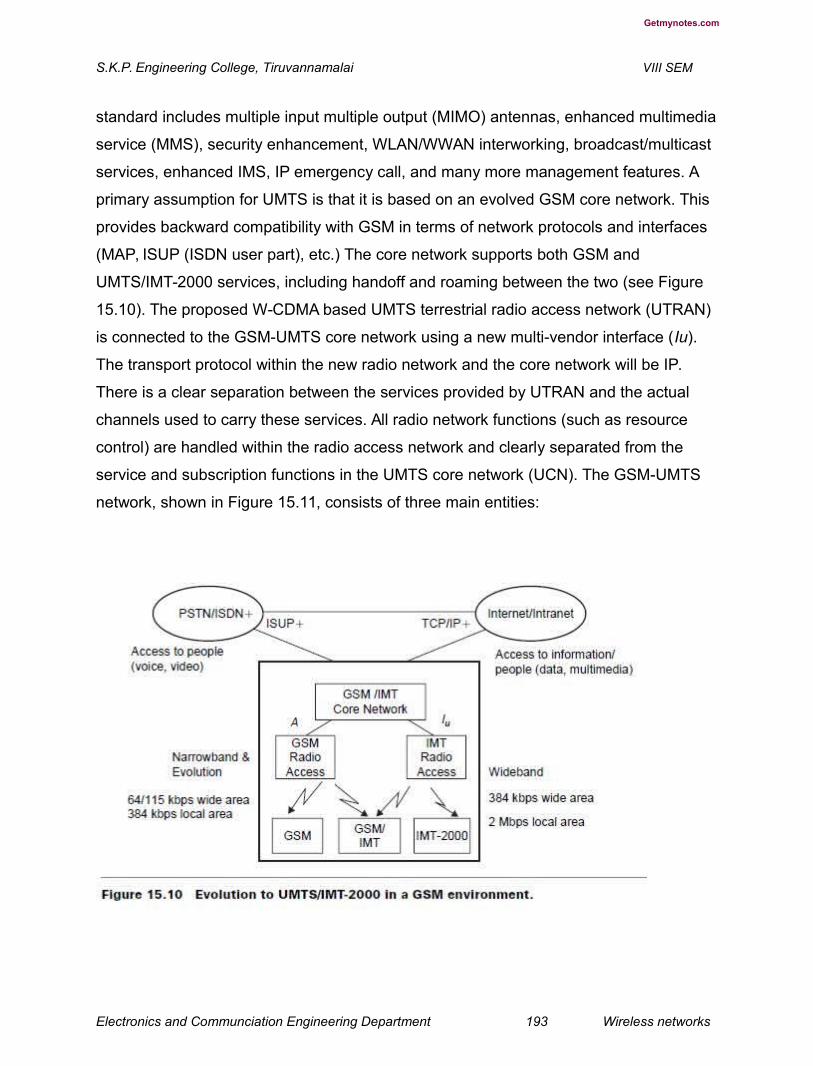
Getmynotes.com
S.K.P. Engineering College, Tiruvannamalai VIII SEM
standard includes multiple input multiple output (MIMO) antennas, enhanced multimedia
service (MMS), security enhancement, WLAN/WWAN interworking, broadcast/multicast
services, enhanced IMS, IP emergency call, and many more management features. A
primary assumption for UMTS is that it is based on an evolved GSM core network. This
provides backward compatibility with GSM in terms of network protocols and interfaces
(MAP, ISUP (ISDN user part), etc.) The core network supports both GSM and
UMTS/IMT-2000 services, including handoff and roaming between the two (see Figure
15.10). The proposed W-CDMA based UMTS terrestrial radio access network (UTRAN)
is connected to the GSM-UMTS core network using a new multi-vendor interface (Iu).
The transport protocol within the new radio network and the core network will be IP.
There is a clear separation between the services provided by UTRAN and the actual
channels used to carry these services. All radio network functions (such as resource
control) are handled within the radio access network and clearly separated from the
service and subscription functions in the UMTS core network (UCN). The GSM-UMTS
network, shown in Figure 15.11, consists of three main entities:
Electronics and Communciation Engineering Department 193 Wireless networks
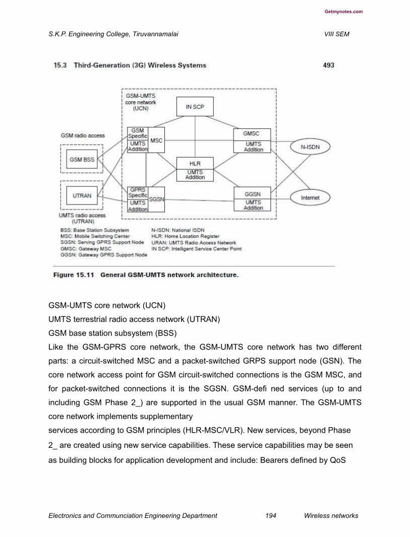
Getmynotes.com
S.K.P. Engineering College, Tiruvannamalai VIII SEM
GSM-UMTS core network (UCN)
UMTS terrestrial radio access network (UTRAN)
GSM base station subsystem (BSS)
Like the GSM-GPRS core network, the GSM-UMTS core network has two different
parts: a circuit-switched MSC and a packet-switched GRPS support node (GSN). The
core network access point for GSM circuit-switched connections is the GSM MSC, and
for packet-switched connections it is the SGSN. GSM-defi ned services (up to and
including GSM Phase 2_) are supported in the usual GSM manner. The GSM-UMTS
core network implements supplementary
services according to GSM principles (HLR-MSC/VLR). New services, beyond Phase
2_ are created using new service capabilities. These service capabilities may be seen
as building blocks for application development and include: Bearers defined by QoS
Electronics and Communciation Engineering Department 194 Wireless networks
Getmynotes.com
S.K.P. Engineering College, Tiruvannamalai VIII SEM
Mobile station execution environment (MExE)
Telephony value-added services (TeleVAS)
Subscriber identity module (SIM) toolkit
Location services
Open interfaces to mobile network functions
Down-loadable application software
Intelligent Network/Customized Applications for Mobile Enhanced Logic(IN/CAMEL) and
service nodes. In addition to new services provided by the GSM-UMTS network itself,
many new services and applications will be realized using a client/server approach, with
servers residing on service local area networks (LANs) outside the GSM-UMTS core
network. For such services, the core network simply acts as a transparent bearer. This
approach is in line with current standardization activities, and is important from a service
continuity point of view. The core network will ultimately be used for the transfer of data
between the end-points, the client and the server.
IN techniques are one way to provide seamless interworking across GSMUMTS
networks. CAMEL already provides the basis for GSM/IN interworking. The IN
infrastructure may be shared by fi xed and mobile networks, and can support fi
xed/mobile service integration, as needed by International Mobile Telecommunications
(IMT). The inherent support for third-party service providers in IN means such providers
could offer all or part of the integrated services. This role of IN is already apparent in
services such as virtual private networks (VPNs), regional
subscription and one number, which are available as network-independent and
customer-driven services. Service nodes and IN can play a complementary role. IN is
suitable for subscription
control and group services where high service penetration in a very wide area with
frequent service invocation are more important than sophistication. Service nodes are
better for providing differentiated user interfaces; e.g., personalcall and messaging
services that use advanced in-band processing and span several access networks.
To make the most of the new radio access network’s capabilities, and to cater to the
large increase in data traffic volume, asynchronous transmission mode (ATM) is used as
the transport protocol within UTRAN and toward the SM-UMTS core network. The
Electronics and Communciation Engineering Department 195 Wireless networks
Getmynotes.com
S.K.P. Engineering College, Tiruvannamalai VIII SEM
combination of an ATM cell-based transport network, WCDMA’s use of variable-rate
speech coding with improved channel coding, and an increased volume of packet data
traffi c over the air interface will mean a saving of about 50% in transmission costs,
compared with equivalent current solutions. ATM, with the newly standardized AAL2
adaptation layer, provides an effi cient transport protocol, optimized for delay-sensitive
speech services and packet data services. Statistical multiplexing in ATM provides
maximum utilization of existing and new transmission infrastructure throughout the
entire network.
In the complex multiservice, multivendor, multiprovider environment of 3G wireless
services network management is a critical issue. The growth of packet data traffi c
requires new ways of charging for services and new billing systems to support them.
There will continue to be a growing demand for better customer care and cost
reductions in managing mobile networks, driven by the need to: Provide sophisticated
personal communications services
Expand the customer base beyond the business user base
Separate the service provider and network operator roles
Provide “one-stop” billing for a range of services
New operations and management functions are needed to support new services and
network functionality. Standardization of interfaces is critical especially for alignment
with current management interfaces in the GSM-UMTS core network. Management
information needs to be part of standard traffi c interfaces. With the right service
strategy and network planning, GSM operators will be able to capitalize on the
wideband multimedia market through a staged evolution of their core networks, with the
addition of new radio access technology as it becomes available.
7.Explain the techniques about UMTS Network Reference Architecture. (L-3,CO-4)
A UMTS system can be divided into a set of domains and the reference points that
interconnect
them. Figures 15.12 and 15.13 show these domains and reference points. A simplifi ed
mapping of functional entities to the domain model is shown in Figure 15.14. Note that
this is a reference model and does not represent any
Electronics and Communciation Engineering Department 196 Wireless networks

Getmynotes.com
S.K.P. Engineering College, Tiruvannamalai VIII SEM
Electronics and Communciation Engineering Department 197 Wireless networks

Getmynotes.com
S.K.P. Engineering College, Tiruvannamalai VIII SEM
architecture. The Iu is split functionally into two logical interfaces, Iups connecting the
packet switched domain to the access network and the Iucs connecting the circuit
switched domain to the access network. The standards do not dictate that these are
physically separate, but the user plane for each is different and the control plane may
be different. The Iur logically connects radio network controllers (RNCs) but could be
physically realized by a direct connection between RNCs or via the core network.
15.5 Channel Structure in UMTS Terrestrial Radio(H-1,CO-4)
Access Network
The UMTS terrestrial radio access network (UTRAN) [10–22] has an access stratum
and nonaccess stratum. The access stratum includes air interface and provides
functions related to OSI layer 1, layer 2, and the lower part of layer 3. The non-access
stratum deals with communication between user equipment (UE) and core network (CN)
and includes OSI layer 3 (upper part) to layer 7. The radio interface, Uu, is the interface
between UE and UTRAN. It consists of three protocol layers: physical layer, data link
layer, and network layer (see Figure 15.15). The radio interface provides physical
channels to carry data over the radio path and logical channels to carry a particular type
of data. There are two types of logical channels: signaling and control, and traffi c
Electronics and Communciation Engineering Department 198 Wireless networks
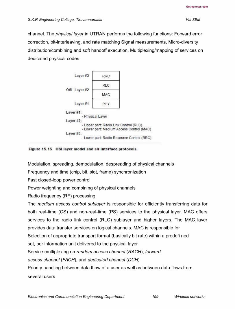
Getmynotes.com
S.K.P. Engineering College, Tiruvannamalai VIII SEM
channel. The physical layer in UTRAN performs the following functions: Forward error
correction, bit-interleaving, and rate matching Signal measurements, Micro-diversity
distribution/combining and soft handoff execution, Multiplexing/mapping of services on
dedicated physical codes
Modulation, spreading, demodulation, despreading of physical channels
Frequency and time (chip, bit, slot, frame) synchronization
Fast closed-loop power control
Power weighting and combining of physical channels
Radio frequency (RF) processing.
The medium access control sublayer is responsible for efficiently transferring data for
both real-time (CS) and non-real-time (PS) services to the physical layer. MAC offers
services to the radio link control (RLC) sublayer and higher layers. The MAC layer
provides data transfer services on logical channels. MAC is responsible for
Selection of appropriate transport format (basically bit rate) within a predefi ned
set, per information unit delivered to the physical layer
Service multiplexing on random access channel (RACH), forward
access channel (FACH), and dedicated channel (DCH)
Priority handling between data fl ow of a user as well as between data flows from
several users
Electronics and Communciation Engineering Department 199 Wireless networks

Getmynotes.com
S.K.P. Engineering College, Tiruvannamalai VIII SEM
Access control on RACH and FACH
Contention resolution on RACH
Radio link control (RLC) sets up a logical link over the radio interface and is responsible
for fulfilling QoS requirements. RLC responsibilities include:
Segmentation and assembly of the packet data unit
Transfer of user data
Error correction through retransmission
Sequence integrity
Duplication information detection
Flow control of data
The radio resource control (RRC) layer broadcasts system information, handles radio
resources (i.e., code allocation, handover, admission control, and measurement/control
report), and controls the requested QoS. The RRC layer offers the following services to
the core network:
General control (GC) service used as an information broadcast service
Notification (Nt) service used for paging and notification of a selected UE
Dedicated control (DC) service used to establish/release a connections and transfer
messages
The channels in UTRAN are physical, transport, and logical (see Figure 15.16).
Electronics and Communciation Engineering Department 200 Wireless networks

Getmynotes.com
S.K.P. Engineering College, Tiruvannamalai VIII SEM
The functions of logical control channels and logical traffi c channels in UTRAN are
listed in Tables 15.4 and 15.5.
In UTRAN transport channels can be either common (i.e., shared between users) or
dedicated channels. They offer information transfer services to the MAC sublayer.
Dedicated transport channels are dedicated channel (DCH) (up link, UL and down link,
DL), fast uplink signaling channel (FAUSCH), and ODMA
Electronics and Communciation Engineering Department 201 Wireless networks

Getmynotes.com
S.K.P. Engineering College, Tiruvannamalai VIII SEM
(opportunity driven multiple access) dedicated channel (ODCH). The common
DL transport channels are listed in Table 15.6.
The mapping between logical and transport channels is given below (see
Figure 15.17):
BCCH is connected to BCH
Electronics and Communciation Engineering Department 202 Wireless networks

Getmynotes.com
S.K.P. Engineering College, Tiruvannamalai VIII SEM
PCCH is connected to PCH
CCCH is connected to RACH and FACH
DTCH can be connected to either RACH and FACH and DSCH, to DCH and DCH, to a
DCH, to a CPCH (FDD mode only)
CTCH can be connected to DSCH, FACH, or BCH
Electronics and Communciation Engineering Department 203 Wireless networks
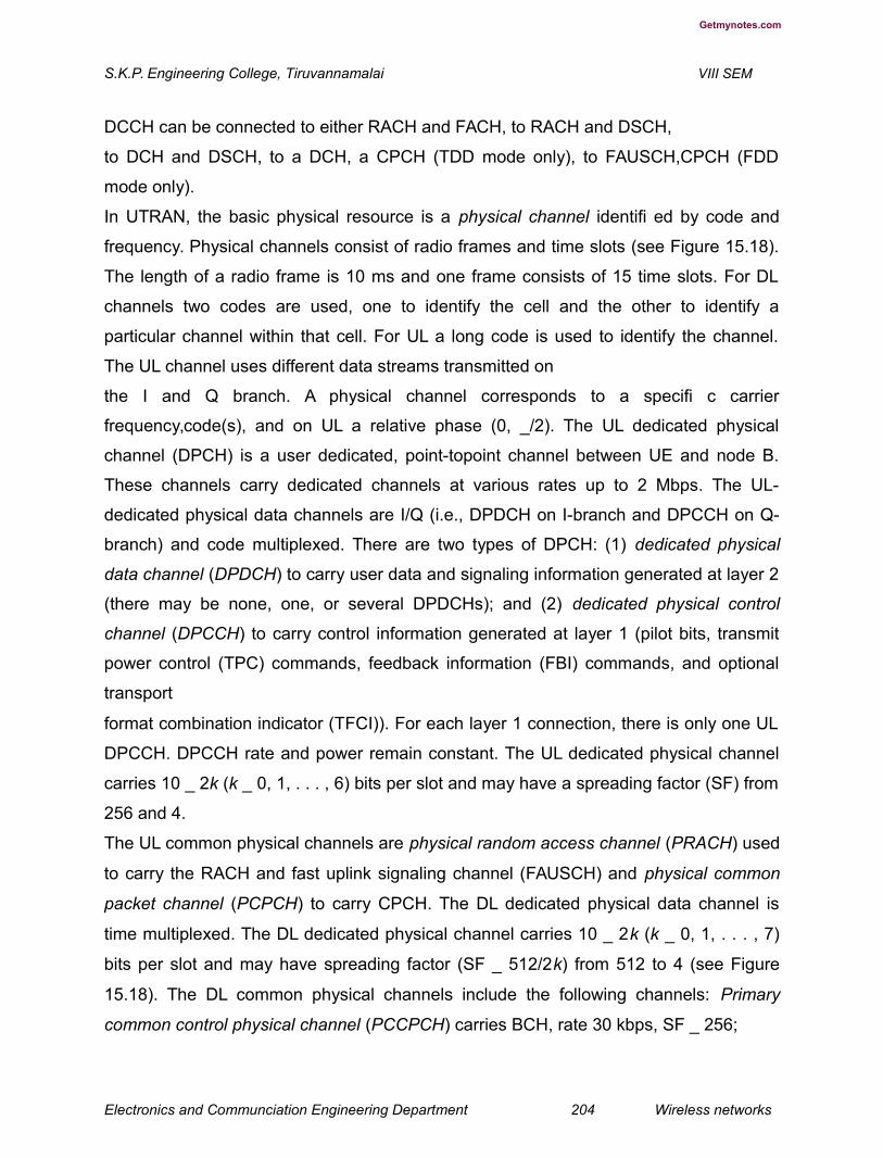
Getmynotes.com
S.K.P. Engineering College, Tiruvannamalai VIII SEM
DCCH can be connected to either RACH and FACH, to RACH and DSCH,
to DCH and DSCH, to a DCH, a CPCH (TDD mode only), to FAUSCH,CPCH (FDD
mode only).
In UTRAN, the basic physical resource is a physical channel identifi ed by code and
frequency. Physical channels consist of radio frames and time slots (see Figure 15.18).
The length of a radio frame is 10 ms and one frame consists of 15 time slots. For DL
channels two codes are used, one to identify the cell and the other to identify a
particular channel within that cell. For UL a long code is used to identify the channel.
The UL channel uses different data streams transmitted on
the I and Q branch. A physical channel corresponds to a specifi c carrier
frequency,code(s), and on UL a relative phase (0, _/2). The UL dedicated physical
channel (DPCH) is a user dedicated, point-topoint channel between UE and node B.
These channels carry dedicated channels at various rates up to 2 Mbps. The UL-
dedicated physical data channels are I/Q (i.e., DPDCH on I-branch and DPCCH on Q-
branch) and code multiplexed. There are two types of DPCH: (1) dedicated physical
data channel (DPDCH) to carry user data and signaling information generated at layer 2
(there may be none, one, or several DPDCHs); and (2) dedicated physical control
channel (DPCCH) to carry control information generated at layer 1 (pilot bits, transmit
power control (TPC) commands, feedback information (FBI) commands, and optional
transport
format combination indicator (TFCI)). For each layer 1 connection, there is only one UL
DPCCH. DPCCH rate and power remain constant. The UL dedicated physical channel
carries 10 _ 2k (k _ 0, 1, . . . , 6) bits per slot and may have a spreading factor (SF) from
256 and 4.
The UL common physical channels are physical random access channel (PRACH) used
to carry the RACH and fast uplink signaling channel (FAUSCH) and physical common
packet channel (PCPCH) to carry CPCH. The DL dedicated physical data channel is
time multiplexed. The DL dedicated physical channel carries 10 _ 2k (k _ 0, 1, . . . , 7)
bits per slot and may have spreading factor (SF _ 512/2k) from 512 to 4 (see Figure
15.18). The DL common physical channels include the following channels: Primary
common control physical channel (PCCPCH) carries BCH, rate 30 kbps, SF _ 256;
Electronics and Communciation Engineering Department 204 Wireless networks
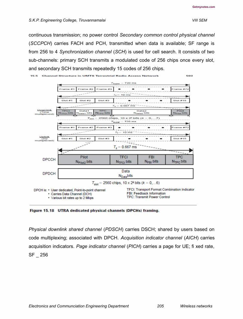
Getmynotes.com
S.K.P. Engineering College, Tiruvannamalai VIII SEM
continuous transmission; no power control Secondary common control physical channel
(SCCPCH) carries FACH and PCH, transmitted when data is available; SF range is
from 256 to 4 Synchronization channel (SCH) is used for cell search. It consists of two
sub-channels: primary SCH transmits a modulated code of 256 chips once every slot,
and secondary SCH transmits repeatedly 15 codes of 256 chips.
Physical downlink shared channel (PDSCH) carries DSCH; shared by users based on
code multiplexing; associated with DPCH. Acquisition indicator channel (AICH) carries
acquisition indicators. Page indicator channel (PICH) carries a page for UE; fi xed rate,
SF _ 256
Electronics and Communciation Engineering Department 205 Wireless networks
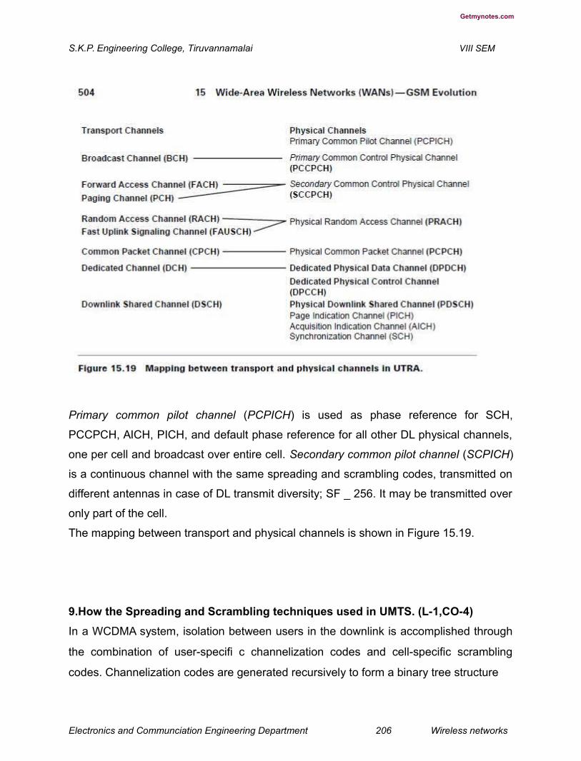
Getmynotes.com
S.K.P. Engineering College, Tiruvannamalai VIII SEM
Primary common pilot channel (PCPICH) is used as phase reference for SCH,
PCCPCH, AICH, PICH, and default phase reference for all other DL physical channels,
one per cell and broadcast over entire cell. Secondary common pilot channel (SCPICH)
is a continuous channel with the same spreading and scrambling codes, transmitted on
different antennas in case of DL transmit diversity; SF _ 256. It may be transmitted over
only part of the cell.
The mapping between transport and physical channels is shown in Figure 15.19.
9.How the Spreading and Scrambling techniques used in UMTS. (L-1,CO-4)
In a WCDMA system, isolation between users in the downlink is accomplished through
the combination of user-specifi c channelization codes and cell-specific scrambling
codes. Channelization codes are generated recursively to form a binary tree structure
Electronics and Communciation Engineering Department 206 Wireless networks

Getmynotes.com
S.K.P. Engineering College, Tiruvannamalai VIII SEM
(see Figure 15.20). Spreading is used in combination with scrambling. Scrambling is
used on top of spreading to separate mobile terminals or cells from each other.
Scrambling does not change the chip rate nor the bandwidth. Transmissions from a
single source are separated by channelization codes based on an orthogonal variable
spreading factor (OVSF) technique (see Appendix D) to allow spreading to be changed
while maintaining orthogonality between codes.When a code is intended to be used, no
other code generated from the intended code can be used; no code between the
intended code and the root code can be used. These restrictions apply to individual
sources; they do not apply to different cells in downlink or different mobile stations in the
uplink. Table 15.7 lists the characteristics of synchronization, channelization, and
scrambling codes used in a WCDMA system.
15.7 UMTS Terrestrial Radio Access Network Overview
The UTRAN consists of a set of radio network subsystems (RNSs) (see Figure 15.21).
The RNS has two main logical elements: Node B and an RNC. The RNS is responsible
for the radio resources and transmission/reception in a set of cells. A cell (sector) is one
coverage area served by a broadcast channel. An RNC is responsible for the use and
Electronics and Communciation Engineering Department 207 Wireless networks

Getmynotes.com
S.K.P. Engineering College, Tiruvannamalai VIII SEM
allocation of all the radio resources of the RNS to which it belongs. The RNC also
handles the user voice and packet data traffi c, performing the actions on the user data
streams that are necessary to access the radio bearers. The responsibilities of an RNC
are:
Intra UTRAN handover
Macro diversity combining/splitting of Iub data streams
Frame synchronization
Radio resource management
Outer loop power control
Iu interface user plane setup
Serving RNS (SRNS) relocation
Radio resource allocation (allocation of codes, etc.)
Frame selection/distribution function necessary for soft handover (functions
of UMTS radio interface physical layer)
UMTS radio link control (RLC) sublayers function execution
Termination of MAC, RLC, and RRC protocols for transport channels,
i.e., DCH, DSCH, RACH, FACH
Iub’s user plane protocols termination
A Node B is responsible for radio transmission and reception in one or more cells
to/from the user equipment (UE). The logical architecture for Node B is
Electronics and Communciation Engineering Department 208 Wireless networks
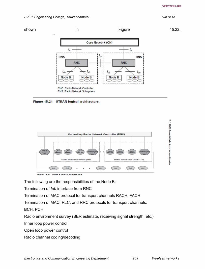
Getmynotes.com
S.K.P. Engineering College, Tiruvannamalai VIII SEM
shown in Figure 15.22.
The following are the responsibilities of the Node B:
Termination of Iub interface from RNC
Termination of MAC protocol for transport channels RACH, FACH
Termination of MAC, RLC, and RRC protocols for transport channels:
BCH, PCH
Radio environment survey (BER estimate, receiving signal strength, etc.)
Inner loop power control
Open loop power control
Radio channel coding/decoding
Electronics and Communciation Engineering Department 209 Wireless networks
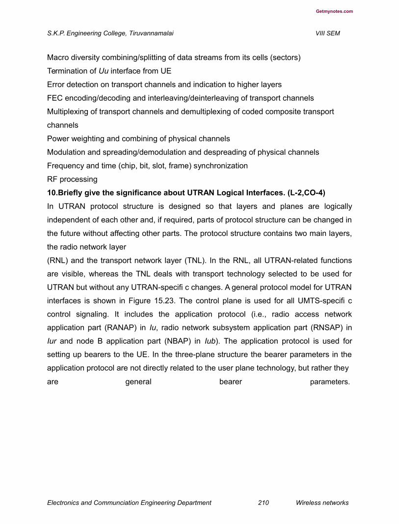
Getmynotes.com
S.K.P. Engineering College, Tiruvannamalai VIII SEM
Macro diversity combining/splitting of data streams from its cells (sectors)
Termination of Uu interface from UE
Error detection on transport channels and indication to higher layers
FEC encoding/decoding and interleaving/deinterleaving of transport channels
Multiplexing of transport channels and demultiplexing of coded composite transport
channels
Power weighting and combining of physical channels
Modulation and spreading/demodulation and despreading of physical channels
Frequency and time (chip, bit, slot, frame) synchronization
RF processing
10.Briefly give the significance about UTRAN Logical Interfaces. (L-2,CO-4)
In UTRAN protocol structure is designed so that layers and planes are logically
independent of each other and, if required, parts of protocol structure can be changed in
the future without affecting other parts. The protocol structure contains two main layers,
the radio network layer
(RNL) and the transport network layer (TNL). In the RNL, all UTRAN-related functions
are visible, whereas the TNL deals with transport technology selected to be used for
UTRAN but without any UTRAN-specifi c changes. A general protocol model for UTRAN
interfaces is shown in Figure 15.23. The control plane is used for all UMTS-specifi c
control signaling. It includes the application protocol (i.e., radio access network
application part (RANAP) in Iu, radio network subsystem application part (RNSAP) in
Iur and node B application part (NBAP) in Iub). The application protocol is used for
setting up bearers to the UE. In the three-plane structure the bearer parameters in the
application protocol are not directly related to the user plane technology, but rather they
are general bearer parameters.
Electronics and Communciation Engineering Department 210 Wireless networks

Getmynotes.com
S.K.P. Engineering College, Tiruvannamalai VIII SEM
User information is carried by the user plane. The user plane includes data stream(s),
and data bearer(s) for data stream(s). Each data stream is characterized by one or
more frame protocols specifi ed for that interface. The transport network control plane
carries all control signaling within the transport layer. It does not include radio network
layer information. It contains
access link control application part (ALCAP) required to set up the transport bearers
(data bearers) for the user plane. It also includes the signaling bearer needed for the
ALCAP. The transport plane lies between the control plane and the user plane. The
addition of the transport plane in UTRAN allows the application protocol in the radio
network control plane to be totally independent of the technology selected for the data
bearer in the user plane. With the transport network control plane, the transport bearers
for data bearers in the user plane are set up in the following way. There is a signaling
transaction by application protocol in the control plane that initiates set-up of the data
bearer by the ALCAP protocol specifi c for the user plane technology.
The independence of the control plane and user plane assumes that an ALCAP
signaling occurs. The ALCAP may not be used for all types of data bearers. If there is
Electronics and Communciation Engineering Department 211 Wireless networks

Getmynotes.com
S.K.P. Engineering College, Tiruvannamalai VIII SEM
no ALCAP signaling transaction, the transport network control plane is not required. This
situation occurs when preconfi gured data bearers are used. Also, the ALCAP protocols
in the transport network control plane are not used to set up the signaling bearer for the
application protocol or the ALCAP during real-time operation.
lu Interface
The UMTS Iu interface is the open logical interface that interconnects one UTRAN to
the UMTS core network (UCN). On the UTRAN side the Iu interface is terminated at the
RNC, and at the UCN side it is terminated at U-MSC. The Iu interface consists of three
different protocol planes — the radio network control plane (RNCP), the transport
network control plane (TNCP), and the user plane (UP). The RNCP performs the
following functions:
It carries information for the general control of UTRAN radio network operations.
It carries information for control of UTRAN in the context of each specifi c call.
It carries user call control (CC) and mobility management (MM) signaling messages.
The control plane serves two service domains in the core network, the packet-switched
(PS) domain and circuit-switched (CS) domain. The CS domain supports circuit-
switched services. Some examples of CS services are voice and fax. The CS domain
can also provide intelligent services such as voice mail and free phone. The CS domain
connects to PSTN/ISDN networks.
The CS domain is expected to evolve from the existing 2G
GSM PLMN.
The PS domain deals with PS services. Some examples of PS services are Internet
access and multimedia services. Since Internet connectivity is provided, all services
currently available on the Internet such as search engines and e-mail are available to
mobile users. The PS domain connects to IP networks. The PS domain is expected to
evolve from the GPRS PLMN.
The Iu circuit-switched and packet-switched protocol architecture are shown
in Figures 15.24 and 15.25.
The control plane protocol stack consists of RANAP on the top of signaling system 7
(SS7) protocols. The protocol layers are the signaling connection control part (SCCP),
the message transfer part (MTP3-B), and signaling asynchronous transfer mode (ATM)
Electronics and Communciation Engineering Department 212 Wireless networks
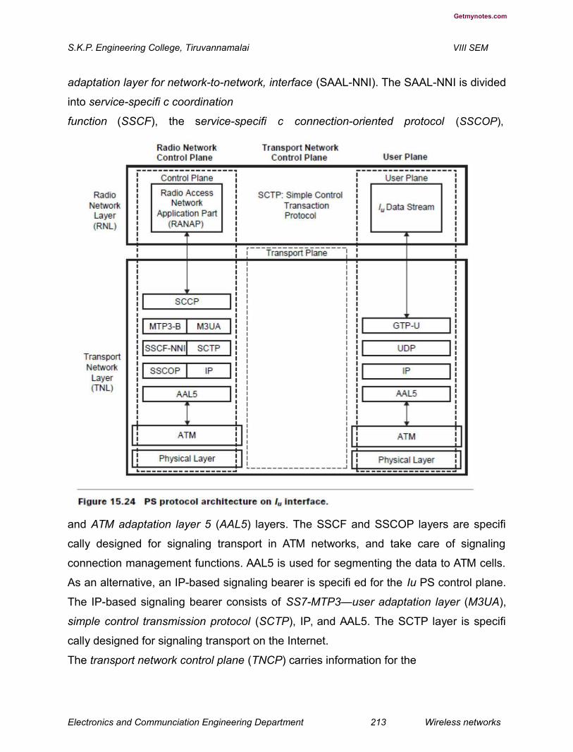
Getmynotes.com
S.K.P. Engineering College, Tiruvannamalai VIII SEM
adaptation layer for network-to-network, interface (SAAL-NNI). The SAAL-NNI is divided
into service-specifi c coordination
function (SSCF), the service-specifi c connection-oriented protocol (SSCOP),
and ATM adaptation layer 5 (AAL5) layers. The SSCF and SSCOP layers are specifi
cally designed for signaling transport in ATM networks, and take care of signaling
connection management functions. AAL5 is used for segmenting the data to ATM cells.
As an alternative, an IP-based signaling bearer is specifi ed for the Iu PS control plane.
The IP-based signaling bearer consists of SS7-MTP3—user adaptation layer (M3UA),
simple control transmission protocol (SCTP), IP, and AAL5. The SCTP layer is specifi
cally designed for signaling transport on the Internet.
The transport network control plane (TNCP) carries information for the
Electronics and Communciation Engineering Department 213 Wireless networks
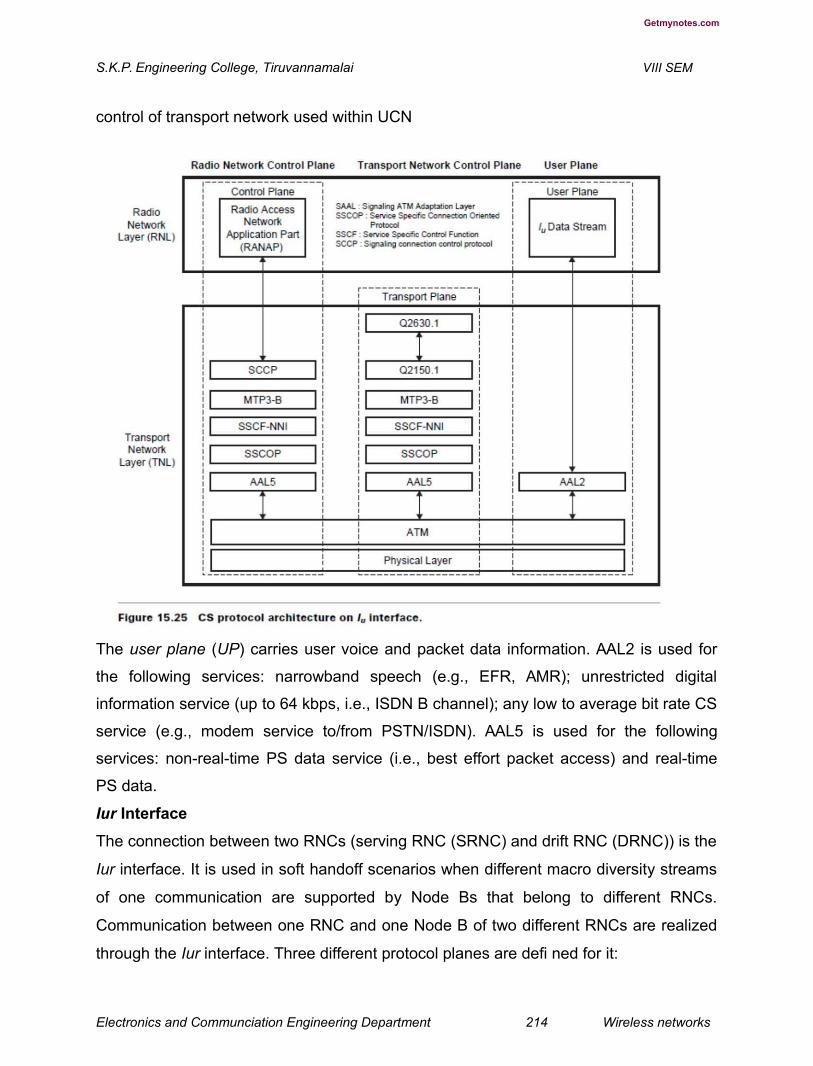
Getmynotes.com
S.K.P. Engineering College, Tiruvannamalai VIII SEM
control of transport network used within UCN
The user plane (UP) carries user voice and packet data information. AAL2 is used for
the following services: narrowband speech (e.g., EFR, AMR); unrestricted digital
information service (up to 64 kbps, i.e., ISDN B channel); any low to average bit rate CS
service (e.g., modem service to/from PSTN/ISDN). AAL5 is used for the following
services: non-real-time PS data service (i.e., best effort packet access) and real-time
PS data.
Iur Interface
The connection between two RNCs (serving RNC (SRNC) and drift RNC (DRNC)) is the
Iur interface. It is used in soft handoff scenarios when different macro diversity streams
of one communication are supported by Node Bs that belong to different RNCs.
Communication between one RNC and one Node B of two different RNCs are realized
through the Iur interface. Three different protocol planes are defi ned for it:
Electronics and Communciation Engineering Department 214 Wireless networks

Getmynotes.com
S.K.P. Engineering College, Tiruvannamalai VIII SEM
Radio network control plane (RNCP)
Transport network control plane (TNCP)
User plane (UP)
The Iur interface is used to carry:
Information for the control of radio resources in the context of specifi c service request
of one mobile on RNCP, Information for the control of the transport network used within
UTRAN
on TNCP, User voice and packet data information on UP
The protocols used on this interface are:
Radio access network application part (RANAP)
DCH frame protocol (DCHFP)
RACH frame protocol (RACHFP)
FACH frame protocol (FACHFP)
Access link control application part (ALCAP)
Q.aal2
Signaling connection control part (SCCP)
Message transfer part 3-B (MTP3-B)
Signaling ATM adaptation layer for network-to-network interface (SAALNNI)
(SAAL-NNI is further divided into service specifi c coordination
function for network to network interface (SSCF-NNI), service specifi
c connection oriented protocol (SSCOP), and ATM adaptation layer 5
(AAL5))
The bearer is AAL2. The protocol structure of the Iur interface is shown in Figure 15.26.
Initially, this interface was designed to support the inter-RNC soft handoff, but more
features were added during the development of the standard. The Iur provides the
following four functions:
1. Basic inter-RNC mobility
support Support of SRNC
relocation
Support of inter-RNC cell and UTRAN registration area
update Support of inter-RNC packet paging
Electronics and Communciation Engineering Department 215 Wireless networks


Getmynotes.com
S.K.P. Engineering College, Tiruvannamalai VIII SEM
Reporting of protocol
errors
2.
Dedicated channel traffi c support
Establishment, modifi cation, and release of a dedicated channel in
the DRNC due to hard and soft handoff in the dedicated channel state
Setup and release of dedicated transport connections across the Iur interface
Transfer of DCH transport blocks between SRNC and DRNC
Management of radio links in the DRNS via dedicated measurement report procedures
and power setting procedures
Electronics and Communciation Engineering Department 216 Wireless networks

Getmynotes.com
S.K.P. Engineering College, Tiruvannamalai VIII SEM
3. Common channel traffi c support
Setup and release of the transport connection across the Iur for common channel data
streams
Splitting of the MAC layer between the SRNC (MAC-d) and DRNC (MAC-c and MAC-
sh); the scheduling for downlink data transmission is performed in the DRNC
Flow control between the MAC-d and MAC-c/MAC-
sh 4. Global resource management support
Transfer of cell measurements between two RNCs
Transfer of Node B timing between two RNCs
lub Interface
The connection between the RNC and Node B is the Iub interface. There is one Iub
interface for each Node B. The Iub interface is used for all of the communications
between Node B and the RNC of the same RNS. Three different protocol planes are
defi ned for it.
Radio network control plane (RNCP)
Transport network control plane (TNCP)
User plane (UP)
The Iub interface is used to carry:
Information for the general control of Node B for radio network operation on RNCP,
Information for the control of radio resources in the context of specifi c service request
of one mobile on RNCP, Information for the control of a transport network used within
UTRAN on TCNP
User CC and MM signaling message on RNCP
User voice and packet data information on UP
The protocols used on this interface include:
Node B application part protocol (NBAP)
DCH frame protocol (DCHFP)
RACH frame protocol (RACHFP)
FACH frame protocol (FACHFP)
Access link control application part (ALCAP)
Electronics and Communciation Engineering Department 217 Wireless networks

Getmynotes.com
S.K.P. Engineering College, Tiruvannamalai VIII SEM
Q.aal2
SSCP or TCP and IP
MTP3-B
SAAL-UNI (SSCF-UNI, SSCOP, and AAL5)
When using multiple low-speed links in the Iub interface, Node B supportsnverse
multiplexing for ATM (IMA).
The bearer is AAL2. The protocol structure for the interface Iub is shown in Figure
15.27.
Uu Interface
The UMTS Uu interface is the radio interface between a Node B and one ofits UE. The
Uu is the interface through which UE accesses the fi xed part of thesystem.
Unit V
PART A
1. How 4G is describeda? (L-1,CO-5)4G is described as MAGIC — Mobile multimedia, Anytime anywhere, Global
mobility support, Integrated wireless solution, and Customized personal service.
The 4G systems will not only support the next generation mobile services, but
also will support the fi xed wireless networks. The 4G systems are about
seamlessly integrating terminals, networks, and applications to satisfy increasing
user demands.
Electronics and Communciation Engineering Department 218 Wireless networks

Getmynotes.com
S.K.P. Engineering College, Tiruvannamalai VIII SEM
2. What are the features of 4G systems? (L-2,CO-5)
High usability: anytime, anywhere, and with any technology
Support for multimedia services at low transmission cost
Personalization
Integrated services
3. What are the applications of 4G system? (L-1,CO-5)
The following are some of the applications of the 4G system:
Virtual presence — 4G will provide user services at all times, even if the user is off-
site.
Virtual navigation — 4G will provide users with virtual navigation through which a
user can access a database of streets, buildings, etc., of a large city. This requires
high speed transmission.
Tele-medicine — 4G will support the remote health monitoring of patients via video
conference assistance for a doctor at anytime and anywhere.
Tele-geo-processing applications — 4G will combine geographical information
systems (GIS) and global positioning systems (GPS) in which a user will get location
querying.
Education — 4G will provide a good opportunity to people anywhere in the world to
continue their education on-line in a cost-effective manner.
4. What is meant by Multi carrier modulation? (L-1,CO-5)
Multicarrier modulation (MCM) is a derivative of frequency-division multiplexing.It is
not a new technology. Forms of multicarrier systems are currently used in DSL
modems and digital audio/video broadcast (DAB/DVB). MCM is a baseband process
that uses parallel equal bandwidth subchannels to transmit information and is
normally implemented with fast Fourier transform (FFT) techniques. MCM’s
advantages are better performance in the inter-symbol-interference environment,
and avoidance of single-frequency interferers. However, MCM increases the peakto-
Electronics and Communciation Engineering Department 219 Wireless networks

Getmynotes.com
S.K.P. Engineering College, Tiruvannamalai VIII SEM
average ratio of the signal, and to overcome inter-symbol-interference a cyclic
extension or guard band must be added to the data.
5. Write the formula for Signal to Noise ratio? (L-2,CO-5)
6. What are the four cases for transmission and reception? (L-3,CO-5)
Single-Input, Single-Output (SISO)
Single-Input, Multiple-Output (SIMO)
Multiple-Input, Single-Output (MISO)
Multiple-Input, Multiple-Output (MIMO)
7. What is meant by BLAST system? (L-1,CO-5)BLAST is a space division multiplexing (SDM)-based MIMO system. It provides
the best trade-off between system performance (spectral effi ciency and capacity)
and system implementation complexity. The spectral effi ciency of BLAST ranges
from 20 to 40 bps/Hz. It uses a zero-forcing (ZF) nonlinear detection algorithm
based on a spatial nulling process combined with symbol cancellation to improve
system performance/
8. What are the steps for ZF algorithm? (L-1,CO-5)
1. Ordering: Determine the optimal detection order.
2. Nulling: Choose the nulling vector to null out all the weaker transmit signals and
obtain the strongest transmit signal.
3. Slicing: Detect the estimated value of the strongest signal by slicing to the nearest
value in the signal constellation.
4. Cancellation: Cancel the effect of the strongest signal from the received signal
vector to reduce the detection complexity for the remaining transmit signal. Go to
step 2 — nulling process.
9. What is the goal for cognitive radio? (L-1,CO-5)
Electronics and Communciation Engineering Department 220 Wireless networks
Getmynotes.com
S.K.P. Engineering College, Tiruvannamalai VIII SEM
The goal of CR is to relieve radio spectrum overcrowding, which actually
translates to a lack of access to full radio spectrum utilization.
10. What is SDR? (L-1,CO-5)Software-defined radios can be reconfigured “on-the-fl y,” i.e., the universal
communication device would reconfigure itself appropriately for the environment.
It could be a cordless phone one minute, a cell phone the next, a wireless
Internet gadget the next, and a GPS receiver the next. Software-defined radios
can be quickly and easily upgraded with enhanced features. In fact, the upgrade
could be delivered over-the-air. Software-defined radios can talk and listen to
multiple channels at the same time
Part B
1. Define the role of 4G system.(L-1,CO-5)
With the rapid development of wireless communication networks, it is
expected
that fourth-generation (4G) mobile systems will be launched within a decade. 4G mobile
systems focus on seamless integration of existing wireless technologies including
WWAN, WLAN, and Bluetooth (see Figure 23.1). This is in contrast with 3G, which
merely focuses on developing new standards and hardware. The recent convergence of
the Internet and mobile radio has accelerated the demand for “Internet in the pocket,” as
well as for radio technologies that increase data throughput and reduce the cost per bit.
Mobile networks are going multimedia, potentially leading to an explosion in throughput
from a few bytes for the short message service (SMS) to a few kilobits per second
(kbps) for the multimedia messaging service (MMS), to several 100 kbps for video
content. In addition to wide area cellular systems, diverse wireless transmission
technologies are being deployed, including digital audio broadcast (DAB) and digital
video broadcast (DVB) for wide-area broadcasting, local multipoint distribution service
(LMDS), and multichannel multipoint distribution service (MMDS) for fi xed wireless
Electronics and Communciation Engineering Department 221 Wireless networks
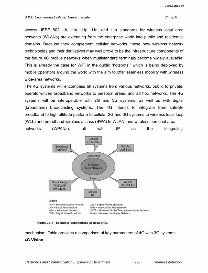
Getmynotes.com
S.K.P. Engineering College, Tiruvannamalai VIII SEM
access. IEEE 802.11b, 11a, 11g, 11n, and 11h standards for wireless local area
networks (WLANs) are extending from the enterprise world into public and residential
domains. Because they complement cellular networks, these new wireless network
technologies and their derivatives may well prove to be the infrastructure components of
the future 4G mobile networks when multistandard terminals become widely available.
This is already the case for WiFi in the public “hotspots,” which is being deployed by
mobile operators around the world with the aim to offer seamless mobility with wireless
wide-area networks.
The 4G systems will encompass all systems from various networks, public to private,
operator-driven broadband networks to personal areas, and ad hoc networks. The 4G
systems will be interoperable with 2G and 3G systems, as well as with digital
(broadband) broadcasting systems. The 4G intends to integrate from satellite
broadband to high altitude platform to cellular 2G and 3G systems to wireless local loop
(WLL) and broadband wireless access (BWA) to WLAN, and wireless personal area
networks (WPANs), all with IP as the integrating
mechanism. Table provides a comparison of key parameters of 4G with 3G systems.
4G Vision
Electronics and Communciation Engineering Department 222 Wireless networks
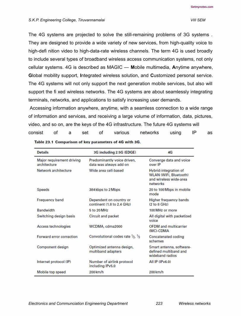
Getmynotes.com
S.K.P. Engineering College, Tiruvannamalai VIII SEM
The 4G systems are projected to solve the still-remaining problems of 3G systems .
They are designed to provide a wide variety of new services, from high-quality voice to
high-defi nition video to high-data-rate wireless channels. The term 4G is used broadly
to include several types of broadband wireless access communication systems, not only
cellular systems. 4G is described as MAGIC — Mobile multimedia, Anytime anywhere,
Global mobility support, Integrated wireless solution, and Customized personal service.
The 4G systems will not only support the next generation mobile services, but also will
support the fi xed wireless networks. The 4G systems are about seamlessly integrating
terminals, networks, and applications to satisfy increasing user demands.
Accessing information anywhere, anytime, with a seamless connection to a wide range
of information and services, and receiving a large volume of information, data, pictures,
video, and so on, are the keys of the 4G infrastructure. The future 4G systems will
consist of a set of various networks using IP as
Electronics and Communciation Engineering Department 223 Wireless networks

Getmynotes.com
S.K.P. Engineering College, Tiruvannamalai VIII SEM
a common protocol. 4G systems will have broader bandwidth, higher data rate,and
smoother and quicker handoff and will focus on ensuring seamless service across a
multiple of wireless systems and networks. The key is to integrate the 4G capabilities
with all the existing mobile technologies through the advanced techniques of digital
communications and networking.
4G Features and Challenges
Some key features (primarily from users’ points of view) of 4G mobile networks
are as follows (see Figure 23.3):
High usability: anytime, anywhere, and with any
technology Support for multimedia services at low
transmission cost Personalization
Integrated services
Electronics and Communciation Engineering Department 224 Wireless networks
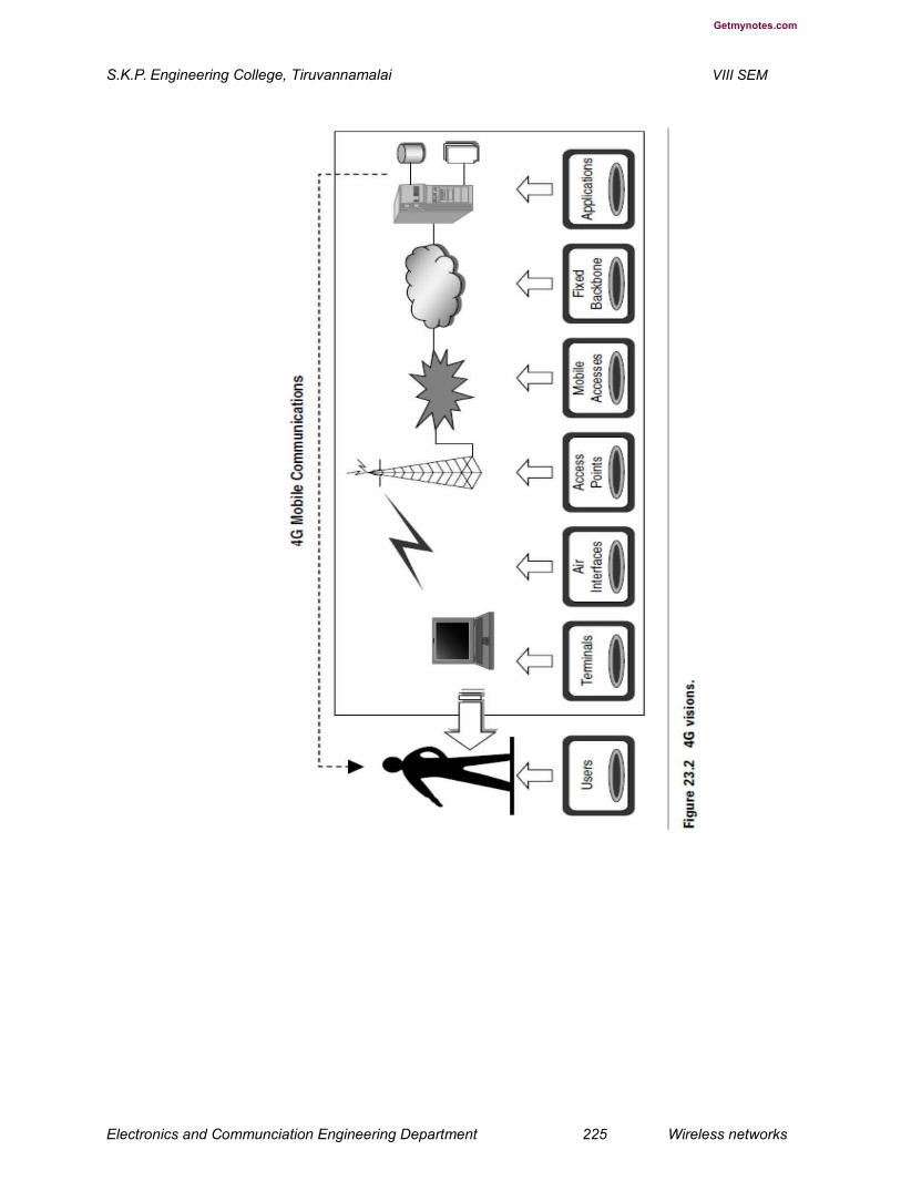
Getmynotes.com
S.K.P. Engineering College, Tiruvannamalai VIII SEM
Electronics and Communciation Engineering Department 225 Wireless networks

Getmynotes.com
S.K.P. Engineering College, Tiruvannamalai VIII SEM
4G networks will be all-IP-based heterogeneous networks that will allow users to use
any system at anytime and anywhere. Users carrying an integrated terminal can use a
wide range of applications provided by multiple wireless networks.
4G systems will provide not only telecommunications services, but also data and
multimedia services. To support multimedia services, high-data-rate services with
system reliability will be provided. At the same time, a low per-bit transmission cost will
be maintained by an improved spectral efficiency of the system.
Personalized service will be provided by 4G networks. It is expected that when 4G
services are launched, users in widely different locations, occupations, and economic
classes will use the services. In order to meet the demands of these diverse users,
service providers will design personal and customized service for them. 4G systems will
also provide facilities for integrated services. Users can use multiple services from any
service provider at the same time. To migrate current systems to 4G with the above-
mentioned features, we have to face a number of challenges. Table lists the key
challenges and their proposed solutions. Figure shows the carriers migration from 3.5G
to 4Gsystems.
Electronics and Communciation Engineering Department 226 Wireless networks
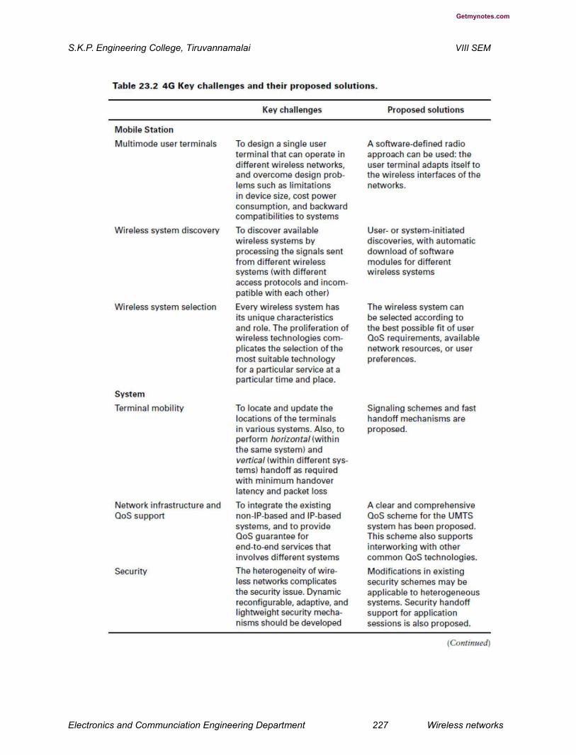
Getmynotes.com
S.K.P. Engineering College, Tiruvannamalai VIII SEM
Electronics and Communciation Engineering Department 227 Wireless networks

Getmynotes.com
S.K.P. Engineering College, Tiruvannamalai VIII SEM
Applications of 4G
The following are some of the applications of the 4G system:
Virtual presence — 4G will provide user services at all times, even if the user
is off-site.
Virtual navigation — 4G will provide users with virtual navigation through
which a user can access a database of streets, buildings, etc., of a large city.
This requires high speed transmission.
Tele-medicine — 4G will support the remote health monitoring of patients via
video conference assistance for a doctor at anytime and anywhere. Tele-geo-
processing applications — 4G will combine geographical information systems
(GIS) and global positioning systems (GPS) in which a user will
get location querying.
Education — 4G will provide a good opportunity to people anywhere in
the world to continue their education on-line in a cost-effective manner.
4G Technologies
Multicarrier Modulation
Multicarrier modulation (MCM) is a derivative of frequency-division multiplexing.It is not
a new technology. Forms of multicarrier systems are currently used in DSL modems and
digital audio/video broadcast (DAB/DVB). MCM is a baseband
Electronics and Communciation Engineering Department 228 Wireless networks

Getmynotes.com
S.K.P. Engineering College, Tiruvannamalai VIII SEM
process that uses parallel equal bandwidth subchannels to transmit information and is
normally implemented with fast Fourier transform (FFT) techniques. MCM’s advantages
are better performance in the inter-symbol-interference environment, and avoidance of
single-frequency interferers. However, MCM increases the peakto- average ratio of the
signal, and to overcome inter-symbol-interference a cyclic extension or guard band
must be added to the data. The difference, D, of the peak-to-average ratio between
MCM and a single carrier system is a function of the number of subcarriers, N, as:
D(dB) _ 10 log N (23.1)
Any increase in the peak-to-average ratio of a signal requires an increase in linearity of
the system to reduce distortion. Linearization techniques can be used, but they increase
the cost of the system.
If Lb is the original length of block, and the channel’s response is of length Lc, the
cyclically extended symbol has a new length Lb _ Lc _ 1. The new symbol of length Lb
Electronics and Communciation Engineering Department 229 Wireless networks

Getmynotes.com
S.K.P. Engineering College, Tiruvannamalai VIII SEM
_ Lc _ 1 sampling periods has no inter-symbol interference. The cost is an increase in
energy and uncoded bits are added to the data. At the MCM receiver, only Lb samples
are processed and Lc _ 1 samples are discarded, resulting in a loss in signal-to-noise
ratio (SNR) as:
Two different types of MCM are likely candidates for 4G. These include multicarrier code
division multiple access (MC-CDMA) and orthogonal frequency division multiplexing
(OFDM) using time division multiple access (TDMA). MC-CDMA is actually OFDM with
a CDMA overlay. Similar to single-carrier CDMA systems, the users are multiplexed with
orthogonal codes to distinguish users in MC-CDMA. However, in MC-CDMA, each user
can be allocated several codes, where the data is spread in time or frequency. Either
way, multiple users simultaneously access the system. In OFDM with TDMA, the users
are assigned time slots to transmit and receive data. Typically MC-CDMA uses
quadrature phase shift keying (QPSK) for modulation, while OFDM with TDMA could
use more high-level modulations, such as multilevel quadrature amplitude modulation
(M-QAM) (where M _ 4 to 256). However, to optimize overall performance, adaptive
modulation can be used, where the level of quadrature amplitude modulation (QAM) for
all subcarriers is chosen based on measured parameters. In OFDM the subcarrier pulse
shape is a square wave. The task of pulse forming and modulation is performed by a
simple inverse fast Fourier transform (IFFT) which can be implemented very effi ciently.
To decode the transmission, a receiver needs only to implement FFT.
Electronics and Communciation Engineering Department 230 Wireless networks

Getmynotes.com
S.K.P. Engineering College, Tiruvannamalai VIII SEM
Th
e OFDM divides a broadband channel into many parallel subchannels. The subchannel
pulse shape is a square wave (see Figure 23.5). The OFDM receiver senses the
channel and corrects distortion on each subchannel before the transmitted data can be
extracted. In OFDM, each of the frequencies is an integer multiple of a fundamental
frequency. This ensures that even though subchannels overlap, they do not interfere
with each other (see Figure).
2. What is a multi-input multi-output (MIMO) system? Explain (L-1,CO-5)
Smart Antenna Techniques
Smart antenna techniques, such as multiple-input multiple-output (MIMO) systems, can
extend the capabilities of the 3G and 4G systems to provide customers with increased
data throughput for mobile high-speed data applications. MIMO systems use multiple
antennas at both the transmitter and receiver to increase the capacity of the wireless
channel (see Figure . With MIMO systems, it may be possible
Electronics and Communciation Engineering Department 231 Wireless networks
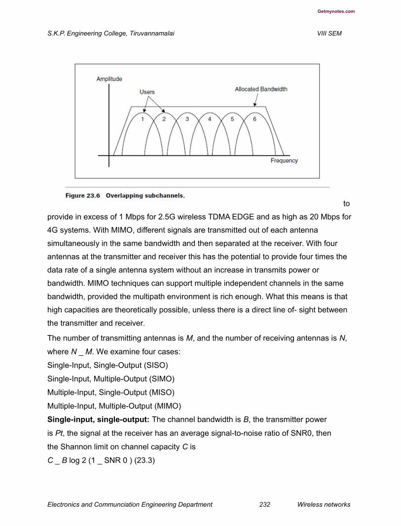
Getmynotes.com
S.K.P. Engineering College, Tiruvannamalai VIII SEM
to
provide in excess of 1 Mbps for 2.5G wireless TDMA EDGE and as high as 20 Mbps for
4G systems. With MIMO, different signals are transmitted out of each antenna
simultaneously in the same bandwidth and then separated at the receiver. With four
antennas at the transmitter and receiver this has the potential to provide four times the
data rate of a single antenna system without an increase in transmits power or
bandwidth. MIMO techniques can support multiple independent channels in the same
bandwidth, provided the multipath environment is rich enough. What this means is that
high capacities are theoretically possible, unless there is a direct line of- sight between
the transmitter and receiver.
The number of transmitting antennas is M, and the number of receiving antennas is N,
where N _ M. We examine four cases:
Single-Input, Single-Output (SISO)
Single-Input, Multiple-Output (SIMO)
Multiple-Input, Single-Output (MISO)
Multiple-Input, Multiple-Output (MIMO)
Single-input, single-output: The channel bandwidth is B, the transmitter power
is Pt, the signal at the receiver has an average signal-to-noise ratio of SNR0, then
the Shannon limit on channel capacity C is
C _ B log 2 (1 _ SNR 0 ) (23.3)
Electronics and Communciation Engineering Department 232 Wireless networks

Getmynotes.com
S.K.P. Engineering College, Tiruvannamalai VIII SEM
Fig :Overlapping subchannels.
Ch23-
Single-input, multiple-output: There are N antennas at the receiver. If the signals
received on the antennas have on average the same amplitude, then they can be added
coherently to produce an N2 increase in signal power. There are N sets of noise
sources that are added coherently and result in an N-fold increase in noise power.
Hence, the overall increase in SNR will be:
Ch23-The capacity for this channel is approximately equal to
Multiple-input, single-output: We have M transmitting antennas. The total power is
divided into M transmitter branches. If the signals add coherently at the receiving
antenna, we get an M-fold increase in SNR as compared to SISO. Because there is
only one receiving antenna, the noise level is same as SISO. The overall increase in
SNR is approximately
Electronics and Communciation Engineering Department 233 Wireless networks

Getmynotes.com
S.K.P. Engineering College, Tiruvannamalai VIII SEM
Multiple-input, multiple-output: MIMO systems can be viewed as a combination of
MISO and SIMO channels. In this case, it is possible to achieve approximately an MN-
fold increase in the average SNR0 giving a channel capacity equal to
Assuming N _ M, we can send different signals using the same bandwidth and still be
able to decode correctly at the receiver. Thus, we are creating a channel for each one of
the transmitters. The capacity of each one of these channels is roughly equal to
Since we have M of these channels (M transmitting antennas), the total
capacity of the system is
We get a linear increase in capacity with respect to the transmitting antennas. As an
example we assume SNR0 is equal to 10 dB, M _ 4, N _ 5 and bandwidth B (MHz) and
list the system capacity for each channel type in Table 23.3.
3. How are higher spectral effi ciency and increased throughput achieved in
the OFDM-MIMO system? (L-3,CO-5)
OFDM and MIMO techniques can be combined to achieve high spectral efficiency and
increased throughput. The OFDM-MIMO system transmits independent OFDM
modulated data from multiple antennas simultaneously. At the receiver, after OFDM
Electronics and Communciation Engineering Department 234 Wireless networks

Getmynotes.com
S.K.P. Engineering College, Tiruvannamalai VIII SEM
demodulation, MIMO decodes each subchannel to extract data from all transmit
antennas on all the subchannels.
Adaptive Modulation and Coding with Time-Slot Scheduler
In general, TCP/IP is designed for a highly reliable transmission medium in wired
networks where packet losses are seldom and are interpreted as congestion in the
network [1]. On the other hand, a wireless network uses a time varying channel where
packet losses may be common due to severe fading. This is misinterpreted by TCP as
congestion which leads to ineffi cient utilization of the available radio link capacity. This
results in signifi cant degradation of the wireless system performance. There is a need
for a system with effi cient packet data transmission using TCP in 4G [2,3,5]. This can
be achieved by using a suitable automatic repeat request (ARQ) scheme combined with
an adaptive modulation and coding system, and a time-slot scheduler that uses channel
predictions. This way, the lower layers are adapted to channel conditions while still
providing some robustness through retransmission. The time-slot scheduler shares the
spectrum efficiently between users while satisfying the QoS requirements.
If the channel quality for each radio link can be predicted for a short duration (say about
10 ms) into the future and accessible by the link layer, then ARQ along with an adaptive
modulation and coding system can be selected for each user to satisfy the bit error rate
(BER) requirement and provide high throughput. The scheduler uses this information
about individual data streams (along with predicted values of different radio links and
selected modulation and coding systems by the link layer) and distributes the time slots
among the users.
Electronics and Communciation Engineering Department 235 Wireless networks

Getmynotes.com
S.K.P. Engineering College, Tiruvannamalai VIII SEM
The planning is done so that the desired QoS and associated priority to
different users are guaranteed while channel spectrum is efficiently utilized.
4.What is Bell Labs Layered Space Time (BLAST) System & Explain (L-1,CO-5)
BLAST is a space division multiplexing (SDM)-based MIMO system. It provides the best
trade-off between system performance (spectral effi ciency and capacity) and system
implementation complexity. The spectral effi ciency of BLAST ranges from 20 to 40
bps/Hz. It uses a zero-forcing (ZF) nonlinear detection algorithm based on a spatial
nulling process combined with symbol cancellation to improve system performance. The
BLAST exploits multipath by using scattering characteristics of the propagation
environment to enhance transmission accuracy. Figure 23.8 shows the architecture of
the BLAST system.
Transmitter: The data stream of a user is divided into multiple substreams. An array of
transmit antennas (M) is used to simultaneously launch parallel data substreams. Each
substream is mapped to a symbol by the same constellation and sent to its transmit
antenna. All substreams are transmitted in the same frequency band and are
independent of one another. Effective transmission rate is increased roughly in
proportion to the number of transmit antennas used. The individual transmitter power is
scaled by 1/M, so that the total power remains constant independent of the number of
transmitters.
Receiver: An array of antennas (N _ M) is used to receive multiple transmitted
substreams and their scattered images. Since substreams originate from different
transmit antennas, they are located at different points in space. Using sophisticated
signal processing, the substreams are identifi ed and recovered.
Model: Each time sequence sj(t), j _ 1, 2, . . . , M is referred to as a layer. At the
receiver, the signal ri(t) is received at time t. It is a noisy superposition of the M
transmitted signal respectively corrupted by noise ni(t):
Electronics and Communciation Engineering Department 236 Wireless networks
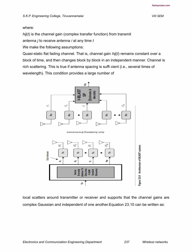
Getmynotes.com
S.K.P. Engineering College, Tiruvannamalai VIII SEM
where:
hij(t) is the channel gain (complex transfer function) from transmit
antenna j to receive antenna i at any time t
We make the following assumptions:
Quasi-static flat fading channel. That is, channel gain hij(t) remains constant over a
block of time, and then changes block by block in an independent manner. Channel is
rich scattering. This is true if antenna spacing is suffi cient (i.e., several times of
wavelength). This condition provides a large number of
local scatters around transmitter or receiver and supports that the channel gains are
complex Gaussian and independent of one another.Equation 23.10 can be written as:
Electronics and Communciation Engineering Department 237 Wireless networks
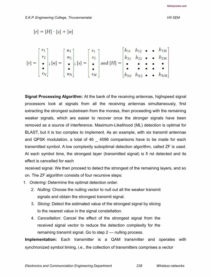
Getmynotes.com
S.K.P. Engineering College, Tiruvannamalai VIII SEM
Signal Processing Algorithm: At the bank of the receiving antennas, highspeed signal
processors look at signals from all the receiving antennas simultaneously, first
extracting the strongest substream from the morass, then proceeding with the remaining
weaker signals, which are easier to recover once the stronger signals have been
removed as a source of interference. Maximum-Likelihood (ML) detection is optimal for
BLAST, but it is too complex to implement. As an example, with six transmit antennas
and QPSK modulation, a total of 46 _ 4096 comparisons have to be made for each
transmitted symbol. A low complexity suboptimal detection algorithm, called ZF is used.
At each symbol time, the strongest layer (transmitted signal) is fi rst detected and its
effect is cancelled for each
received signal. We then proceed to detect the strongest of the remaining layers, and so
on. The ZF algorithm consists of four recursive steps:
1. Ordering: Determine the optimal detection order.
2. Nulling: Choose the nulling vector to null out all the weaker transmit
signals and obtain the strongest transmit signal.
3. Slicing: Detect the estimated value of the strongest signal by slicing
to the nearest value in the signal constellation.
4. Cancellation: Cancel the effect of the strongest signal from the
received signal vector to reduce the detection complexity for the
remaining transmit signal. Go to step 2 — nulling process.
Implementation: Each transmitter is a QAM transmitter and operates with
synchronized symbol timing, i.e., the collection of transmitters comprises a vector
Electronics and Communciation Engineering Department 238 Wireless networks
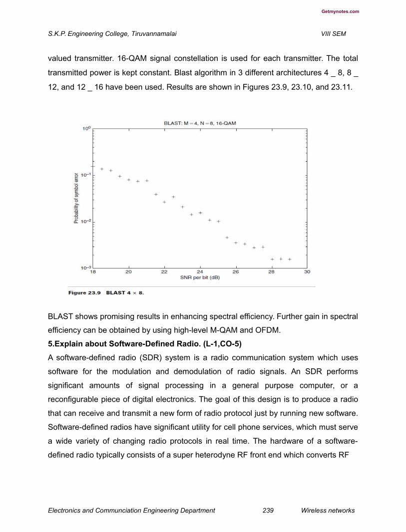
Getmynotes.com
S.K.P. Engineering College, Tiruvannamalai VIII SEM
valued transmitter. 16-QAM signal constellation is used for each transmitter. The total
transmitted power is kept constant. Blast algorithm in 3 different architectures 4 _ 8, 8 _
12, and 12 _ 16 have been used. Results are shown in Figures 23.9, 23.10, and 23.11.
BLAST shows promising results in enhancing spectral efficiency. Further gain in spectral
efficiency can be obtained by using high-level M-QAM and OFDM.
5.Explain about Software-Defined Radio. (L-1,CO-5)
A software-defined radio (SDR) system is a radio communication system which uses
software for the modulation and demodulation of radio signals. An SDR performs
significant amounts of signal processing in a general purpose computer, or a
reconfigurable piece of digital electronics. The goal of this design is to produce a radio
that can receive and transmit a new form of radio protocol just by running new software.
Software-defined radios have significant utility for cell phone services, which must serve
a wide variety of changing radio protocols in real time. The hardware of a software-
defined radio typically consists of a super heterodyne RF front end which converts RF
Electronics and Communciation Engineering Department 239 Wireless networks

Getmynotes.com
S.K.P. Engineering College, Tiruvannamalai VIII SEM
signals from and to analog RF signals, and analog to digital converters and digital to
analog converters which are used to convert digitized intermediate
frequency (IF) signals from and to analog form, respectively. Software-defined radio can
currently be used to implement simple radio modem technologies. In the long run, SDR
is expected to become the dominant technology in radio communications. The following
are some of the things that SDR can do that haven’t been possible before:
Software-defined radios can be reconfigured “on-the-fl y,” i.e., the universal
communication device would reconfigure itself appropriately for the environment. It
could be a cordless phone one minute, a cell phone the next, a wireless Internet gadget
the next, and a GPS receiver the next. Software-defined radios can be quickly and
easily upgraded with enhanced features. In fact, the upgrade could be delivered over-
the-air. Software-defined radios can talk and listen to multiple channels at the same
time.
Electronics and Communciation Engineering Department 240 Wireless networks

Getmynotes.com
S.K.P. Engineering College, Tiruvannamalai VIII SEM
New kinds of radios can be built that have never before existed. Smart radios or
cognitive radios (CRs) can look at the utilization of the RF spectrum in their immediate
neighbourhood and configure themselves for the best performance.
6.What is Cognitive Radio? (L-1,CO-5)
With the CR paradigm, spectrum can be efficiently shared in a more flexible fashion by
a number of operators/users/systems. The CR can be viewed as an enabling
technology that will benefi t several types of users by introducing new communications
and networking models for the whole wireless world, creating better business
opportunities for the incumbent operators and new technical dimensions for smaller
operators, and helping shape an overall more efficient approach regarding spectrum
requirements and usage in the next generation wireless networks.
The CR can be regarded as an extension of SDR. In 2003, the IEEE Committee on
Communications and Information Policy (CCIP) recommended CR. for consideration by
the FCC as a means to conserve valuable spectrum utilization. The CR focuses on
applying software capabilities that have been developed to support algorithm control
Electronics and Communciation Engineering Department 241 Wireless networks
Getmynotes.com
S.K.P. Engineering College, Tiruvannamalai VIII SEM
across a wide spectrum of signal processing technologies to add smarts to the software
that allows it to determine when frequencies are free to use and then use them in the
most efficient manner possible.
Most of the research work currently is focusing on spectrum sensing cognitive radio —
particularly on the utilization of TV bands for communication. The essential problem of
spectrum sensing CR is the design of high quality sensing devices and algorithms for
exchanging spectrum sensing data between nodes. It has been shown in [6] that a
simple energy detector cannot guarantee accurate detection of signal presence. This
calls for more sophisticated spectrum sensing techniques and requires that information
about spectrum sensing be exchanged between nodes regularly.
It is not implicit that a CR must be software-defi ned radio. It is possible to implement
CR features — the ability to detect and avoid (protect) incumbent users — while using
relatively conventional radio transmitter/receiver architectures and techniques. The goal
of CR is to relieve radio spectrum overcrowding, which actually translates to a lack of
access to full radio spectrum utilization.
Electronics and Communciation Engineering Department 242 Wireless networks