ŠKODA Roomster Owner's...
194
SIMPLY CLEVER ŠKODA Roomster Owner's Manual
Transcript of ŠKODA Roomster Owner's...

SIMPLY CLEVER
ŠKODA RoomsterOwner's Manual

Layout of this Owner's Manual(explanations)
This Owner's Manual has been systematically designed to make it easy for you tosearch for and obtain the information you require.
Chapters, table of contents and subject indexThe text of the Owner's manual is divided into relatively short sections which arecombined into easy-to-read chapters. The chapter you are reading at any particularmoment is always specified on the bottom right of the page.
The Table of contents is arranged according to the chapters and the detailed Sub-ject index at the end of the Owner's Manual helps you to rapidly find the informa-tion you are looking for.
Direction indicationsAll direction indications such as “left”, “right”, “front”, “rear” relate to the direction oftravel of the vehicle.
Units of measurementAll values are expressed in metric units.
Explanation of symbols Denotes a reference to a section with important information and safety
advice in a chapter.
Denotes the end of a section.
Denotes the continuation of a section on the next page.
Indicates situations where the vehicle must be stopped as soon as possi-ble.
® Denotes a registered trademark.
Notes
WARNING
The most important notes are marked with the heading WARNING. TheseWARNING notes draw your attention to a serious risk of accident or injury.
CAUTION
A Caution note draws your attention to the possibility of damage to your vehicle(e.g. damage to gearbox), or points out general risks of an accident.
For the sake of the environment
An Environmental note draws your attention to environmental protection aspects.This is where you will, for example, find tips aimed at reducing your fuel consump-tion.
Note
A normal Note draws your attention to important information about the operationof your vehicle.

Preface
You have opted for a ŠKODA – our sincere thanks for your confidence in us.You have received a vehicle with the latest technology and range of amenities. Please read this Owner'sManual carefully, because the operation in accordance with these instructions is a prerequisite for proper useof the vehicle.
If you have any questions about your vehicle, please contact a ŠKODA Service Partner.
We wish you much pleasure with your ŠKODA and pleasant motoring at all times.
Your ŠKODA AUTO a.s. (hereinafter referred to as ŠKODA) £

The on-board literatureThe on-board literature for your vehicle consists of this “Owner's Manual” as wellas a “Service schedule” and the “Help on the road” brochure.
Depending on the vehicle model and equipment, other additional operating man-uals and instructions may be provided (e.g. an operating manual for the radio).
If one of the publications listed above is missing, please contact a ŠKODA ServicePartner.
The Owner's ManualThese operating instructions describe all possible equipment variants withoutidentifying them as special equipment, model variants or market-dependentequipment.
Consequently, this vehicle does not need to contain all of the equipment compo-nents described in this Owner's manual.
The level of equipment of your vehicle refers to your purchase contract of the ve-hicle. For more information, contact your local ŠKODA retailer.
The illustrations can differ in minor details from your vehicle; they are only inten-ded for general information.
The Service Plan:› includes vehicle data including information on service work performed;› is a record of services provided;› is provided for entries relating to the mobility warranty (valid only for some
countries);› serves as warranty certificate of the ŠKODA dealer.
The service records are one of the conditions for warranty claims.
Please always present the Service schedule when you take your car to a ŠKODAspecialist garage.
If the Service Schedule is missing or worn, please contact the ŠKODA specialistgarage that regularly services your car. You will receive a duplicate, in which thepreviously carried out service work is confirmed by the ŠKODA specialist garage.
The Help on the Road brochureThe brochure contains the important emergency telephone numbers as well astelephone numbers and contact addresses of ŠKODA Service Partners in differentcountries.

Table of Contents
Abbreviations
Using the system
Cockpit 7Overview 6
Instruments and Indicator Lights 8Instrument cluster 8Multifunction display (onboard computer) 12MAXI DOT (information display) 15Warning lights 17
Unlocking and locking 25Vehicle key 25Locking/unlocking the vehicle without centrallocking 26Central locking system 27Remote control 29Anti-theft alarm system 30Interior monitor and towing protection 31Emergency locking of the doors 31Boot lid 32Electrical power windows 33Panorama roof 35
Lights and visibility 36Lights 36Interior light 41Visibility 42Windscreen wipers and washers 42Rear window 45
Seats and Stowage 47Front seats 47Head restraints 48Rear seats 49
Boot 51Variable loading floor in the boot 55Bicycle carrier in the luggage compartment 56Roof rack system 58Cup holders 59Ashtray 60Cigarette lighter, 12-volt power socket 60Storage compartments 61Clothes hooks 65Parking ticket holder 66
Heating and air conditioning system 67Heating and air conditioning system 67Air outlet vents 68Heating 68Air conditioning system (manual air conditioningsystem) 70Climatronic (automatic air conditioningsystem) 73
Starting-off and Driving 76Starting and stopping the engine 76Brakes and brake assist systems 78Shifting (manual gearbox) 82pedals 82Parking aid 82Cruise control system (CCS) 83START/STOP 85
Automatic gearbox 87Automatic gearbox 87
Communication 92Mobile phones and two-way radio systems 92Universal telephone preinstallation GSM II 92Voice control 96Multimedia 97
Safety
Passive Safety 100General information 100Correct seated position 101
Seat belts 104Seat belts 104
Airbag system 109Description of the airbag system 109Front airbags 110Side airbags 111Head airbags 112Deactivating airbags 113
Transporting children safely 115Child seat 115
Driving Tips
Driving and the Environment 119The first 1 500 km 119Catalytic converter 119Economical and environmentally friendlydriving 120Environmental compatibility 122Driving abroad 123Avoiding damage to your vehicle 123Driving through water on the street 124
Towing a trailer 125Towing a trailer 125
General Maintenance
Taking care of and cleaning the vehicle 127Taking care of your vehicle 127
3Table of Contents

Inspecting and replenishing 134Fuel 134Engine compartment 136Vehicle battery 143
Wheels and Tyres 148Tyres 148
Accessories, changes and replacement of parts 155Introductory information 155Changes and impairments of the airbagsystem 155
Do-it-yourself
Do-it-yourself 156First-aid kit and warning triangle 156Fire extinguisher 156Vehicle tool kit 156Changing a wheel 157Breakdown kit 160Jump-starting 163Towing the vehicle 164
Fuses and light bulbs 166Fuses 166Bulbs 169
Praktik
Praktik 174Rear interior light 174Lashing eyes 174Adjustable safety partition behind the frontseats 174Fixing of the loading floor 175Adjustment of the safety partition 175Emergency unlocking of the loading area door 175
Technical data
Technical data 176Introductory information 176Data on the vehicle sticker and the type plate 176Dimensions 178Specifications and engine oil capacity 179Vehicle-specific details per engine type 180
Index
4 Table of Contents

Abbreviations
Abbreviation Definition
rpm Engine revolutions per minute
ABS Anti-lock brake system
AG Automatic gearbox
TCS Traction control
CO2 in g/km discharged quantity of carbon dioxide in grams per driven kilo-meter
DPF Diesel particle filter
DSG Automatic double clutch gearbox
ESC Electronic Stability Control
kW Kilowatt, measuring unit for the engine output
MG Manual gearbox
MFD Multifunction display
N1 Panel van intended exclusively or mainly for the transporta-tion of goods
Nm Newton meter, measuring unit for the engine torque
TDI CR Diesel engine with turbocharging and common rail injectionsystem
TSI Petrol engine with turbocharging and direct injection Ð
5Abbreviations

Fig. 1 Cockpit
6 Using the system

Using the system
Cockpit
Overview
Electrical power windows 33Electric exterior mirror adjustment 45Air outlet vents 68Lever for the multifunction switch:› Turn signal light, headlight and parking light, headlight flasher 40› Speed regulating system 83Steering wheel:› With horn› With driver’s front airbag 110› With pushbuttons for radio, navigation system and mobile
phone 92Instrument cluster: Instruments and warning lights 8Lever for the multifunction switch:› Multifunction display 12› Windscreen wiper and wash system 43Switch for rear window heater 42TCS switch 81Air outlet vents 68Switch for hazard warning lights 40Warning light for the deactivated front seat passenger airbag 113Depending on equipment fitted:› Operating controls for the heating 68› Operating controls for the air conditioning system 70› Operating controls for Climatronic 73Storage compartments on the front passenger side 62Front passenger airbag 110Key-operated switch for the front seat passenger airbag 113Switch depending on equipment fitted:› Boot lid remote release 32› Interior monitor 31
1
2
3
4
5
6
7
8
9
10
11
12
13
14
15
16
17
Fuse box in the dashboard 167Light switch and headlamp beam adjustment 36, 39Bonnet release lever 138Lever for adjusting the steering wheel 77Ignition lock 78Depending on equipment fitted:› Radio› Navigation systemRocker switch for front left seat heating 48Central locking system 28Depending on equipment fitted:› Gearshift lever (manual gearbox) 82› Selector lever (automatic gearbox) 88Rocker switch for front right seat heating 48Depending on equipment fitted:› Ashtrays 60› Storage compartment 63MDI 99
Note
The arrangement of the controls and switches and the location of some items onright-hand drive models may differ from that shown in » Fig. 1. The symbols onthe controls and switches are the same as for left-hand drive models. Ð
18
19
20
21
22
23
24
25
26
27
28
29
7Cockpit

Instruments and Indicator Lights
Instrument cluster
ä Introduction
This chapter contains information on the following subjects:
Overview 8Engine revolutions counter 9Speedometer 9Coolant temperature gauge 9Fuel gauge 9Counter for distance driven 10Service Interval Display 10Digital clock 11Recommended gear 11
WARNING
■ Concentrate fully at all times on your driving! As the driver you are fully re-sponsible for road safety.■ Never operate the controls in the instrument cluster while driving, onlywhen the vehicle is stationary! Ð
Overview
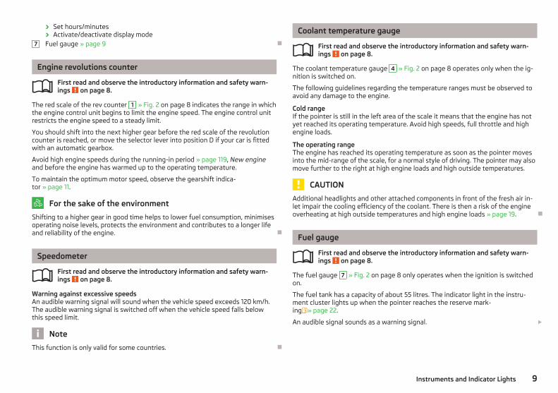
Fig. 2 Instrument cluster
First read and observe the introductory information and safety warn-ings on page 8.
Engine revolutions counter » page 9Display:› With counter for distance driven » page 10› With service interval display » page 10› With digital clock » page 11› With multifunction display » page 12› With information display » page 15Speedometer » page 9Coolant temperature gauge » page 9Button for display mode:› Set hours/minutes› Activating/deactivating the second speed in mph or km/h› Service interval - Display of the number of days, kilometres or miles re-
maining until the next Inspection Service 1)
Button for:› Reset trip counter for the distance driven› Resetting Service Interval Display £
ä1
2
3
4
5
6
1) Valid for countries where the values are indicated in British measuring units.
8 Using the system
› Set hours/minutes› Activate/deactivate display modeFuel gauge » page 9 Ð
Engine revolutions counter
First read and observe the introductory information and safety warn-ings on page 8.
The red scale of the rev counter 1 » Fig. 2 on page 8 indicates the range in whichthe engine control unit begins to limit the engine speed. The engine control unitrestricts the engine speed to a steady limit.
You should shift into the next higher gear before the red scale of the revolutioncounter is reached, or move the selector lever into position D if your car is fittedwith an automatic gearbox.
Avoid high engine speeds during the running-in period » page 119, New engineand before the engine has warmed up to the operating temperature.
To maintain the optimum motor speed, observe the gearshift indica-tor » page 11.
For the sake of the environment
Shifting to a higher gear in good time helps to lower fuel consumption, minimisesoperating noise levels, protects the environment and contributes to a longer lifeand reliability of the engine. Ð
Speedometer
First read and observe the introductory information and safety warn-ings on page 8.
Warning against excessive speedsAn audible warning signal will sound when the vehicle speed exceeds 120 km/h.The audible warning signal is switched off when the vehicle speed falls belowthis speed limit.
Note
This function is only valid for some countries. Ð
7
ä
ä
Coolant temperature gauge
First read and observe the introductory information and safety warn-ings on page 8.
The coolant temperature gauge 4 » Fig. 2 on page 8 operates only when the ig-nition is switched on.
The following guidelines regarding the temperature ranges must be observed toavoid any damage to the engine.
Cold rangeIf the pointer is still in the left area of the scale it means that the engine has notyet reached its operating temperature. Avoid high speeds, full throttle and highengine loads.
The operating rangeThe engine has reached its operating temperature as soon as the pointer movesinto the mid-range of the scale, for a normal style of driving. The pointer may alsomove further to the right at high engine loads and high outside temperatures.
CAUTION
Additional headlights and other attached components in front of the fresh air in-let impair the cooling efficiency of the coolant. There is then a risk of the engineoverheating at high outside temperatures and high engine loads » page 19. Ð
Fuel gauge
First read and observe the introductory information and safety warn-ings on page 8.
The fuel gauge 7 » Fig. 2 on page 8 only operates when the ignition is switchedon.
The fuel tank has a capacity of about 55 litres. The indicator light in the instru-ment cluster lights up when the pointer reaches the reserve mark-ing» page 22.
An audible signal sounds as a warning signal. £
ä
ä
9Instruments and Indicator Lights

CAUTION
Never drive until the fuel tank is completely empty! An irregular supply of fuel canlead to irregular engine running. Unburnt fuel may get into the exhaust systemand damage the catalytic converter.
Note
On some vehicles, the fuel gauge is shown in the display of the instrument clus-ter. Ð
Counter for distance driven
First read and observe the introductory information and safety warn-ings on page 8.
The distance which you have driven with your vehicle is shown in kilometres (km).In some countries the measuring unit “mile” is used.
Daily trip counter (trip)The daily trip counter indicates the distance which you have driven since it waslast reset - in steps of 100 metres or 1/10 of a mile.
To reset the display of the daily trip counter, press button 6 » Fig. 2 on page 8for longer.
OdometerThe odometer indicates the total distance in kilometres or miles which the vehiclehas been driven.
Fault displayIf there is a fault in the instrument cluster Error will appear continuously in thedisplay. Ensure the fault is rectified as soon as possible by ŠKODA a specialist ga-rage.
Note
For vehicles fitted with the information display, if the display of the second speedis activated in mph or km/h, this driving speed is indicated instead of the counterfor the total distance driven. Ð
ä
Service Interval Display
Fig. 3 Service Interval Display: Note
First read and observe the introductory information and safety warn-ings on page 8.
The display can vary depending on the equipment.
Service Interval DisplayBefore the next service interval a key symbol and the remaining kilometres areindicated for 10 seconds after switching on the ignition » Fig. 3. At the same time,the remaining days until the next service interval are displayed.
The following is displayed in the information display:
Service in ... km or ... days.
The kilometre indicator or the days indicator reduces in steps of 100 km or, whereapplicable, days until the service due date is reached.
As soon as the due date for the service is reached, a flashing key symbol andthe text Service appears in the display for 20 seconds after the ignition has beenswitched on.
The following is displayed in the information display:
Service now!
Displaying the distance and days until the next service intervalYou can use the button 5 to display the remaining distance and days until thenext service interval » Fig. 2 on page 8.
A key symbol and the remaining distance appear for 10 seconds in the display.At the same time, the remaining days until the next service interval are displayed.
On vehicles which are equipped with the information display, you can call up thisdisplay in the menu Settings » page 15. £
ä
10 Using the system

The following will be displayed in the information display for 10 seconds:
Service in ... km or ... days.
Resetting Service Interval DisplayIt is only possible to reset the Service Interval Display, if a service message or atleast a pre-warning is shown in the instrument cluster display.
We recommend that this reset is completed by a ŠKODA specialist garage.
The ŠKODA specialist garage:› Resets the memory of the display after the appropriate inspection› Adds an entry to the Service Schedule› Affixes the sticker with the entry of the following service interval to the side of
the dashboard on the driver's side
Reset the service interval display by using the reset button 6 » Fig. 2 on page 8.
On vehicles which are equipped with the information display, you can reset theService Interval Display in the menu Settings » page 15.
CAUTION
We recommend that you do not reset the Service Interval Display yourself as thiscan result in the incorrect setting of the Service Interval Display, which can alsocause possible problems with the operation of your vehicle.
Note
■ Never reset the display between service intervals, as this will result in the incor-rect display.■ Information is retained in the Service Interval Display even after the vehicle bat-tery is disconnected.■ If the instrument cluster is exchanged after a repair, the correct values must beentered in the counter for the Service Interval Display. This work is carried out bya ŠKODA specialist garage.■ After resetting the display with flexible service intervals, the displayed data isthe same as that for a vehicle with fixed service intervals. We therefore recom-mend that the Service Interval Display is only reset by a ŠKODA Service Partner,who will reset the display with a vehicle system tester.■ For more information on the service intervals » Service Plan. Ð
Digital clock
First read and observe the introductory information and safety warn-ings on page 8.
The clock is set with the buttons 5 and 6 » Fig. 2 on page 8.
Select the display that you wish to change with the button 5 and carry out thechange with the button 6 .
On vehicles that are fitted with the information display, it is also possible to setthe clock in the menu Time » page 15. Ð
Recommended gear
Fig. 4 Recommended gear
First read and observe the introductory information and safety warn-ings on page 8.
The currently engaged gear A is shown in the instrument cluster display » Fig. 4.
In order to minimise the fuel consumption, a recommendation for shifting into an-other gear is indicated in the display.
If the control unit recognises that it is beneficial to change gear, an arrow B isshown in the display. The arrow points up or down, depending on whether youshould shift into a higher or lower gear.
At the same time, the recommended gear is indicated instead of the currently en-gaged gear A . £
ä
ä
11Instruments and Indicator Lights

CAUTION
The driver is always responsible for selecting the correct gear in different drivingsituations, such as overtaking. Ð
Multifunction display (onboard computer)
ä Introduction
This chapter contains information on the following subjects:
Memory 12Operation 13Multifunction display details 13Warning against excessive speeds 14
The multifunction display can only be operated when the ignition is switched on.After the ignition is switched on, the function displayed is the one which you lastselected before switching off the ignition.
The multi-functional indicator appears in the display » Fig. 5 on page 12 or in theinformation display » page 15 depending on the equipment fitted to your vehi-cle.
In vehicles with an information display » page 15, there is an option to fade outsome of the information.
WARNING
■ Concentrate fully at all times on your driving! As the driver you are fully re-sponsible for road safety.■ Do not only rely upon the information given on the outside temperature dis-play that there is no ice on the road. Even at temperatures around +4 °C, blackice may still be on the road surface – warning, drive with care!
Note
■ In certain national versions the displays appear in the Imperial system of meas-ures.■ If the display of the second speed is activated in mph, the current speed is notindicated in km/h on the display. Ð
Memory
Fig. 5 Multifunction display
First read and observe the introductory information and safety warn-ings on page 12.
The multifunction display is equipped with two automatic memories. The selectedmemory is shown in the Display » Fig. 5.
The data of the single-trip memory (memory 1) is shown if a 1 appears in the dis-play. A 2 shown in the display means that data relates to the total distance mem-ory (memory 2).
Switching over the memory takes place with the button B » Fig. 6 on page 13on the windshield wiper lever.
Single-trip memory (memory 1)The single-trip memory collates the driving information from the moment the ig-nition is switched on until it is switched off. New data will also flow into the cal-culation of the current driving information if the trip is continued within 2 hoursafter switching off the ignition. If the trip is interrupted for more than 2 hours,the memory is automatically erased.
Total-trip memory (memory 2)The total-trip memory gathers data from any number of individual journeys up toa total of 19 hours and 59 minutes driving or 1 999 kilometres driven, and on vehi-cles which are fitted with an information display up to a total of 99 hours and59 minutes driving or 9 999 kilometres driven. The memory is deleted when ei-ther of these limits is reached and the calculation starts all over again.
Unlike the single-trip memory, the total-trip memory is not deleted after a periodof interruption of driving of 2 hours. £
ä
12 Using the system

Note
All information in the memory 1 and 2 is erased if the battery of the vehicle is dis-connected. Ð
Operation
Fig. 6 Multifunction display: Control el-ements
First read and observe the introductory information and safety warn-ings on page 12.
The rocker switch A » Fig. 6 and the button B are located on the windscreenwiper lever.
Select memory› Press the button B » Fig. 6.
Selecting functions› Briefly press the rocker switch A » Fig. 6 up or down. This opens the individual
functions of the multifunction display one after the other.
Reseting› Select the desired memory.› Press the button B » Fig. 6 for longer.
The following readouts of the selected memory will be set to zero by button B :
› Average fuel consumption› Distance driven
ä
› Average speed› Driving time Ð
Multifunction display details
First read and observe the introductory information and safety warn-ings on page 12.
Outside temperatureThe current outside temperature is shown in the display.
If the outside temperature drops below +4 °C, a snow flake symbol (warning sig-nal for ice on the road) appears before the temperature indicator and an audiblesignal will sound. After pressing the rocker switch A » Fig. 6 on page 13, thefunction which was shown last is indicated.
Driving timeThe driving time which has elapsed since the memory was last erased, appears inthe display. If you want to measure the driving time from a particular moment intime on, at this moment, reset the memory by setting the button B » Fig. 6 onpage 13 to zero.
The maximum time indicated in both memories is 19 hours and 59 minutes and onvehicles which are fitted with an information display, it is 99 hours and 59 mi-nutes. The indicator is set back to zero if this period is exceeded.
Current fuel consumptionThe current fuel consumption level is shown in the display in litres/100 km1). Youcan use this information to adapt your driving style to the desired fuel consump-tion.
The display appears in litres/hour if the vehicle is stationary or driving at a lowspeed2).
Average fuel consumptionThe average fuel consumption since the memory was last erased is shown in thedisplay in litres/100 km1) » page 12. £
ä
1) On some models in certain countries, the display appears in kilometres/litre.2) On some models in certain countries, the display appears in --,- kilometres/litres if the vehicle is sta-
tionary.
13Instruments and Indicator Lights

If you wish to determine the average fuel consumption over a certain period oftime, you must set the memory at the start of the new measurement to zero us-ing the button B » Fig. 6 on page 13. After erasing the memory, no value appearsin the display until you have driven approx. 300 m.
The display is updated regularly while you are driving.
RangeThe estimated range in kilometres is shown on the display. It indicates the dis-tance you can still drive with your vehicle based on the level of fuel in the tankand the same style of driving.
The display is shown in steps of 10 km. Once the fuel gauge pointer reaches thereserve marking, the range is displayed in 5 km.
The fuel consumption over the last 50 km is used to calculate the range. Therange will increase if you drive in a more economical manner.
If the memory is set to zero (after disconnecting the battery), the fuel consump-tion of 10 ltr./100 km is calculated for the range; afterwards the value is adaptedaccordingly to the style of driving.
Distance travelledThe distance travelled since the memory was last erased is shown in the dis-play » page 12. If you want to measure the distance travelled from a particularmoment in time on, at this moment, reset the memory by setting the buttonB » Fig. 6 on page 13 to zero.
The maximum distance indicated in both memories is 1 999 km or 9 999 km onvehicles with an information display. The indicator is set back to zero if this periodis exceeded.
Average speedThe average speed since the memory was last erased is shown in the display inkm/hour » page 12. To determine the average speed over a certain period of time,set the memory to zero at the start of the measurement using button B » Fig. 6on page 13.
After erasing the memory, no value appears in the display until you have drivenapprox. 300 m.
The display is updated regularly while you are driving.
Current speedThe current speed which is identical to the display of the speedometer 3 » Fig. 2on page 8 is indicated on the display.
Oil temperatureIf the oil temperature is lower than 50 °C or if a fault in the system for checkingthe oil temperature is present, only - -.- is displayed instead of the oil tempera-ture. Ð
Warning against excessive speeds
First read and observe the introductory information and safety warn-ings on page 12.
Adjust the speed limit while the vehicle is stationary› With button A » Fig. 6 on page 13, choose the menu point Warning against ex-
cessive speeds.› Press the button B to activate the ability to set the speed limit (value flashes).› Use the button A to adjust the required speed limit, e.g. to 50 km/h.› Confirm the speed limit that was set with button B , or wait approx. 5 seconds
until the setting is saved automatically (the value stops flashing).
This allows you to set the speed in 5 km/h intervals.
Adjusting the speed limit while the vehicle is moving› With button A » Fig. 6 on page 13, choose the menu point Warning against ex-
cessive speeds.› You can drive at the desired speed, e.g. 50 km/h.› Press button B to accept the current speed as the speed limit (the value flash-
es).
If you wish to change the set speed limit, it is changed in 5 km/h intervals (e.g. theaccepted speed of 47 km/h increases to 50 km/h or decreases to 45 km/h).› Confirm the speed limit that was set by pressing button B again, or wait ap-
prox. 5 seconds until the setting is saved automatically (the value stops flash-ing).
Change or delete speed limit› With button A » Fig. 6 on page 13, choose the menu point Warning against ex-
cessive speeds.› Pressing the button B deletes the speed limit.› Pressing the button B activates the ability to change the speed limit.
If the set speed limit is exceeded, an audible signal will sound as a warning. Atthe same time the message Warning against excessive speeds appears on thedisplay with the set limit value.
The set speed limit value remains stored even after switching off the ignition. Ð
ä
14 Using the system

MAXI DOT (information display)
ä Introduction
This chapter contains information on the following subjects:
Main menu 15Settings 15Door, boot lid and bonnet warning 16Auto Check Control 16
The information display provides you with information on the current operatingstate of your vehicle. The information system also provides you with data (de-pending on the equipment installed in the vehicle) relating to the radio, mobilephone, multi-functional indicator, navigation system, the unit connected to theMDI input and the automatic gearbox » page 87.
Certain functions and operating conditions are always being checked on the vehi-cle when the ignition is switched on and also while driving.
Lighting up of certain symbols is combined with an acoustic warning signal.
WARNING
Concentrate fully at all times on your driving! As the driver you are fully re-sponsible for road safety. Ð
Main menu
Fig. 7 Windshield wiper lever: Controlsfor the information display
First read and observe the introductory information and safety warn-ings on page 15.ä
› Activate the Main menu by pressing the rocker switch A » Fig. 7 for longer.› Individual menu items can be selected by means of the rocker switch A . When
the pushbutton B is briefly pressed, the information you have selected is dis-played.
The following information can be selected (depending on the equipment installedon the vehicle):
■ MFD » page 12■ Audio » Operating instructions for the radio■ Navigation » Operating instructions for the navigation system■ Phone » page 92■ Vehicle status » page 16■ Settings » page 15
The menu items Audio and Navigation are only displayed when the factory-fittedradio or navigation system is switched on.
Note
If the information display is not activated at that moment, the menu always shiftsto one of the higher levels after 10 seconds. Ð
Settings
First read and observe the introductory information and safety warn-ings on page 15.
You can change certain settings by means of the information display. The currentsetting is shown on the information display in the respective menu at the top be-low the line.
The following information can be selected (depending on the equipment installedon the vehicle):
■ Language■ MFD Data■ Time■ Winter tyres■ Units■ Alt. speed dis.■ Service■ Factory Setting■ Back £
ä
15Instruments and Indicator Lights

Select the menu item Back to return to one level higher in the menu.
LanguageYou can set the language for the warning and information texts here.
MFD displaysActivate or deactivate certain displays of the multifunction display here.
TimeThe time, time format (12 or 24 hour indicator) and the changeover between sum-mer/winter time can be set here.
Winter tyresHere, you can set the speed at which an audible signal should sound. This func-tion is, for example, used for winter tyres where the maximum permissible speedis lower than the maximum speed of the vehicle.
When exceeding the speed, the following is shown on the information display:
Winter tyres max. speed ...km/h.
Units of measurementThe units for the temperature, consumption and distance driven can be set here.
Second speedThe display of the second speed in mph or in km/h can be switched on here1).
Service )Here you can have the remaining kilometres and days until the next service inter-val displayed, and reset the Service Interval Display.
Factory settingAfter selecting the menu Factory setting the factory setting of the informationdisplay is restored. Ð
Door, boot lid and bonnet warning
First read and observe the introductory information and safety warn-ings on page 15.
If at least one door is open, or the boot or bonnet is open, the information displayindicates the relevant open door or boot/bonnet.
An audible signal also sounds if the vehicle is travelling at more than 6 km/h. Ð
ä
Auto Check Control
First read and observe the introductory information and safety warn-ings on page 15.
Vehicle conditionCertain functions and conditions of individual vehicle systems are checked contin-uously when the ignition is switched on and also while driving.
Some error messages and other information are displayed in the information dis-play. The messages are displayed at the same time as the symbols in the informa-tion display or the warning lights in the instrument cluster » page 17.
If there is at least one error message, the menu item Vehicle status is displayedin the menu. After selecting this menu the first of the error messages is dis-played. Several error messages are shown on the display under the message e.g.1/3. This indicates that the first of a total of three error messages is being dis-played.
As long as the operational faults are not rectified, the symbols are always indica-ted again. After they are displayed for the first time, the symbols continue to beindicated without any extra messages for the driver.
Warning symbols
Engine oil pressure too low » page 19
Clutches of the automatic gearbox are toohot
» page 16
Check engine oil level,engine oil sensor faulty
» page 19
Clutches of the automatic gearbox are too hotA symbol in the information display indicates that the temperature of theclutches of the automatic gearbox is too high.
The following is displayed in the information display:
Gearbox overheated. Stop! Owner's man.!
Stop the vehicle, switch off the engine, and wait until the symbol disappears -risk of gearbox damage! You can continue your journey as soon as the symbol dis-appears. £
ä
1) Valid for countries where the values are indicated in British measuring units.
16 Using the system

WARNING
If you have to stop for technical reasons, then park the vehicle at a safe dis-tance from the traffic, switch off the engine and activate the hazard warninglight system » page 40.
Note
■ If warning messages are shown in the information display, you need to confirmthese messages with the button B » Fig. 7 on page 15 in order to call up the mainmenu.■ As long as the operational faults are not rectified, the symbols are always indi-cated again. After they are displayed for the first time, the symbols continue to beindicated without any extra messages for the driver. Ð
Warning lights
Overview
The warning lights show certain functions/faults and may be accompanied by au-dible signals.
Handbrake » page 18
Brake system » page 18
Fastening the seat belt » page 18
Generator » page 18
Open door » page 19
Engine oil » page 19
Coolant temperature/coolant level » page 19
Electrohydraulic power steering » page 20
Electronic Stability Control (ESC) » page 20
Traction control (TCS) » page 21
Antilock brake system (ABS) » page 21
Rear fog light » page 21
Bulb failure » page 21
Exhaust inspection system » page 21
Glow plug system (diesel engine) » page 22
EPC fault light (petrol engine) » page 22
Diesel particle filter (diesel engine) » page 22
Fuel reserve » page 22
Airbag system » page 23
Tyre control display » page 23
Windscreen washer fluid level » page 23
Traction control (TCS) switched off » page 23
Turn signal (left/right). » page 23
Low beam » page 23
Fog lights » page 24 £
17Instruments and Indicator Lights

Speed regulating system » page 24
Selector lever lock » page 24
Main beam » page 24
WARNING
■ If illuminated warning lights and the corresponding descriptions and warn-ing notes are not observed, this may result in severe injuries or major vehicledamage.■ The engine compartment of your car is a hazardous area. There is a risk ofinjuries, scalding, accidents and fire when working in the engine compart-ment, e.g. inspecting and replenishing oil and other fluids. It is essential to ob-serve safety notes » page 136, Engine compartment. Ð
Handbrake
The warning light comes on if the handbrake is applied. An audible warning isalso given if you drive the vehicle for at least 3 seconds at a speed of more than6 km/h.
The following is displayed in the information display:
Release parking brake! Ð
Brake system
The warning light illuminates if the brake fluid level is too low or there is afault in the ABS.
The following is displayed in the information display:
Brake fluid: Owner's manual!
Stop the vehicle, switch off the engine, and check the level of the brake flu-id » page 142.
Further information » page 78, Brakes and brake assist systems.
WARNING
■ If you have to stop for technical reasons, then park the vehicle at a safe dis-tance from the traffic, switch off the engine and activate the hazard warninglight system » page 40.■ The following guidelines should be observed when opening the bonnet andchecking the brake fluid level » page 136, Engine compartment.■ If the warning light is displayed simultaneously with warning light » page 21, Antilock brake system (ABS) , do not continue your jour-ney! Seek help from a ŠKODA specialist garage.■ A fault to the braking system can increase the vehicle's braking distance! Ð
Seat belt warning light
The warning light comes on after the ignition is switched on as a reminder forthe driver to fasten the seat belt. The warning light only goes out if the driver hasfastened his seat belt.
If the seat belt has not been fastened by the driver, a permanent warning signalsounds at vehicle speeds greater than 20 km/h and simultaneously the warninglight flashes.
If the seat belt is not fastened by the driver during the next 90 seconds, thewarning signal is deactivated and the warning light lights up permanently.
Further information » page 104, Seat belts. Ð
Dynamo
If the warning light lights up when the engine is running, the vehicle battery isnot being charged.
Seek help from a ŠKODA specialist garage. The electrical system requires check-ing.
WARNING
If you have to stop for technical reasons, then park the vehicle at a safe dis-tance from the traffic, switch off the engine and activate the hazard warninglight system » page 40, Switches for the hazard warning light system. £
18 Using the system

CAUTION
If the warning light (cooling system fault) comes on in addition to the warninglight when driving, stop the vehicle immediately and switch the engine off -risk of engine damage! Ð
Open door
The warning light comes on if one or several doors are opened or if the boot lidis opened.
The warning light comes on even when the ignition is switched off. The warninglight lights up for a maximum of 5 minutes.
WARNING
If you have to stop for technical reasons, then park the vehicle at a safe dis-tance from the traffic, switch off the engine and activate the hazard warninglight system » page 40, Switches for the hazard warning light system. Ð
warning light
The warning light lights up red (low oil pressure)The following is displayed in the information display:
Oil Pressure: Engine off! Owner's manual!
The warning light comes on for a few seconds when the ignition is switchedon1).
Stop the vehicle, switch off the engine, and check the level of the engineoil » page 139, Checking the engine oil level.
Even if the oil level is correct, do not drive any further if the warning light isflashing. Also do not leave the engine running at an idling speed.
Seek help from a ŠKODA specialist garage.
The warning light lights up yellow (oil quantity too low)The following is displayed in the information display:
Check oil level!
Stop the vehicle, switch off the engine, and check the level of the engineoil » page 139, Checking the engine oil level.
An audible signal sounds as a warning signal.
The warning light will go out if the bonnet is left open for more than 30 seconds.If no engine oil has been replenished, the warning light will come on again afterdriving about 100 km.
The warning light flashes yellow (engine oil level sensor faulty)The following is displayed in the information display:
Oil sensor: Workshop!
If the engine oil level sensor is faulty, the warning light flashes several timesand an audible signal sounds when the ignition is turned on.
Seek help from a ŠKODA specialist garage.
WARNING
If you have to stop for technical reasons, then park the vehicle at a safe dis-tance from the traffic, switch off the engine and activate the hazard warninglight system » page 40.
CAUTION
The red oil pressure light is not an oil level indicator! One should thereforecheck the oil level at regular intervals, preferably after every refuelling stop. Ð
Coolant temperature/coolant level
The indicator light lights up until the engine reaches operating temperature2).Avoid high speeds, full throttle and high engine loads.
If the warning light lights up or flashes, either the coolant temperature is toohigh or the coolant level is too low. £
1) The warning light on vehicles fitted with an information display does not come on after switchingthe ignition on, but only if a fault exists or the engine oil level is too low.
2) Not valid for vehicles with information display.
19Instruments and Indicator Lights

An audible signal sounds as a warning tone.
The following is displayed in the information display:
Check coolant! Owner's manual!
Stop the vehicle, switch off the engine, check the level of the coolant » page 141,and refill the coolant if necessary » page 141.
If the coolant is within the specified range, the increased temperature may becaused by an operating problem at the radiator fan. Check the fuse for the radia-tor fan, replace if necessary » page 168, Fuses in the engine compartment.
Do not continue driving if the warning light does not go off even though thecoolant level is correct and the fuse for the fan is in working order!
Seek help from a ŠKODA specialist garage.
WARNING
■ If you have to stop for technical reasons, then park the vehicle at a safe dis-tance from the traffic, switch off the engine and activate the hazard warninglight system » page 40.■ Carefully open the coolant expansion bottle. If the engine is hot, the coolingsystem is pressurized - risk of scalding! It is therefore best to allow the engineto cool down before removing the cap.■ Do not touch the radiator fan. The radiator fan may switch itself on auto-matically even if the ignition is off. Ð
Electrohydraulic power steering
The warning light comes on for a few seconds when the ignition is switchedon.
If the warning light after switching on the ignition or when driving lights up con-tinuously, a fault exists in the electrohydraulic power steering. The power steer-ing operates with reduced steering assist or does not function at all.
Seek help from a ŠKODA specialist garage.
Further information » page 77.
Note
■ If the yellow warning light goes out when you restart the engine and drivefor a short distance, it is not necessary to visit a ŠKODA specialist garage.■ If the vehicle battery has been disconnected and reconnected, the yellow warn-ing light comes on after switching on the ignition. The warning light should goout after driving a short distance.■ There is no power-assisted steering support when the vehicle is being towedwithout the engine running or when the power-assisted steering is defect. Thevehicle is fully steerable however. There is however increased force required toturn the steering wheel. Ð
Electronic Stability Control (ESC)
The warning light flashes to show that the ESC is currently operating.
If the warning light comes on immediately after you start the engine, the ESCmight be switched off due to technical reasons. Switch the ignition off and onagain. If the warning light does not light up after you switch the engine back on,the ESR is fully functional again.
If the warning light lights up, there is a fault in the ESC.
The following is displayed in the information display:
Error: Electronic Stability Control (ESC)
Seek help from a ŠKODA specialist garage.
The ESC cannot be switched off, the button » page 81 only deactivates theTCS system and the warning light in the instrument cluster lights up.
As the ESC operates in conjunction with the ABS, the ESP indicator light will alsocome on if the ABS system fails.
Further information » page 80, Stabilisation control (ESC).
Note
If the vehicle's battery has been disconnected and reconnected, the warning light comes on after switching on the ignition. The warning light should go out afterdriving a short distance. Ð
20 Using the system

Traction control system (TCS)
The warning light flashes to show that the ASR is currently operating.
If the warning light comes on immediately after starting the engine, the ASRcan be switched off for technical reasons. Switch the ignition off and on again. Ifthe warning light does not light up after you switch the engine back on, the ASRis fully functional again.
If the warning light lights up, there is a fault in the ASR.
The following is displayed in the information display:
Error: traction control (ASR)
Seek help from a ŠKODA specialist garage.
The fact that the TCS system operates together with the ABS means that the TCSwarning light will also come on if the ABS system is not operating properly.
Further information » page 81, Traction control system (TCS).
Note
If the vehicle's battery has been disconnected and reconnected, the warning light comes on after switching on the ignition. The warning light should go out afterdriving a short distance. Ð
Antilock brake system (ABS)
If the warning light lights up, there is a fault in the ABS.
The following is displayed in the information display:
Error: ABS
The vehicle will only be braked by the normal brake system without the ABS.
Seek help from a ŠKODA specialist garage.
WARNING
■ If you have to stop for technical reasons, then park the vehicle at a safe dis-tance from the traffic, switch off the engine and activate the hazard warninglight system » page 40.■ If the warning light » page 18 is displayed simultaneously with the ABSwarning light , do not continue your journey! Seek help from a ŠKODAspecialist garage.■ A fault to the ABS system or the braking system can increase the vehicle'sbraking distance - risk of accident! Ð
The rear fog light
The warning light comes on when the rear fog lights are operating » page 39. Ð
Bulb failure
The warning light comes on if a bulb is faulty:› within 2 seconds of the ignition being switched on;› when switching on the defective light bulb.
The following is displayed in the information display:
Check front-right dipped beam!
Note
The rear side lights and the licence plate lighting have several light bulbs. The in-dicator light only lights up if all light bulbs of the licence plate lighting or theparking light (in one rear light) are defective. For this reason, regular check thatthese light bulbs are working correctly. Ð
Exhaust inspection system
If the warning light lights up, there is a fault in the exhaust inspection system.The engine control unit allows the vehicle to run in emergency mode.
Seek help from a ŠKODA specialist garage. Ð
21Instruments and Indicator Lights

Glow plug system (diesel engine)
The warning light comes on after the ignition has been switched on. The en-gine can be started immediately after the pre-glow warning light goes out.
There is a fault in the glow plug system if the warning light does not come onat all or lights up continuously.
If the warning light begins to flash while driving, a fault exists in the enginecontrol. The engine control unit allows the vehicle to run in emergency mode.
Seek help from a ŠKODA specialist garage. Ð
EPC fault light (petrol engine)
If the warning light comes on or begins to flash while driving, a fault exists inthe engine control unit. The engine control unit allows the vehicle to run in emer-gency mode.
Seek help from a ŠKODA specialist garage. Ð
Diesel particulate filter (diesel engine)
The diesel particulate filter separates the soot particles from the exhaust. Thesoot particles collect in the diesel particulate filter where they are burnt on a reg-ular basis.
If the warning light lights up, soot has accumulated in the diesel particulatefilter.
To clean the diesel particle filter, the vehicle should be driven at an even speed ofat least 60 km/h » at engine speeds of 1 800 - 2 500 rpm for at least 15 mi-nutes or until the warning light goes out, in 4th or 5th gear (automatic gearbox:position S) when the traffic situation permits it.
The warning light only goes out after the diesel particulate filter has beensuccessfully cleaned.
If the filter is not properly cleaned, the warning light does not go out and thewarning light begins to flash.
The following is displayed in the information display:
Diesel particulate filter: Owner's manual
The engine control unit allows the vehicle to run in emergency mode. Afterswitching the ignition off and on again the indicator light, the indicator light also lights up.
Seek help from a ŠKODA specialist garage.
WARNING
■ The diesel particle filter achieves very high temperatures. Therefore do notpark in areas where the hot filter can come into direct contact with dry grassor other combustible materials - risk of fire!■ Always adjust your speed to suit weather, road, region and traffic condi-tions. The recommendations indicated by the warning light must not temptyou to disregard the national regulations for road traffic.
CAUTION
As long as the warning light lights up, one must take into account an in-creased fuel consumption and in certain circumstances a power reduction of theengine.
Note
■ To assist the combustion process of the soot particles, we recommend that reg-ularly driving over short distances should be avoided.■ Using diesel fuel with an increased sulphur content can considerably reduce thelife of the diesel particle filter. A ŠKODA specialist garage will be able to tell youwhich countries use only diesel fuel with high sulphur content. Ð
Fuel reserve
The indicator light will come on if the fuel level is less than 7 litres.
An audible signal sounds as a warning signal.
The following is displayed in the information display:
Please refuel! Range ... km
Note
The text in the information display goes out only after refuelling and driving ashort distance. Ð
22 Using the system
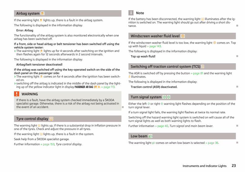
Airbag system
If the warning light lights up, there is a fault in the airbag system.
The following is displayed in the information display:
Error: Airbag
The functionality of the airbag system is also monitored electronically when oneairbag has been switched off.
If a front, side or head airbag or belt tensioner has been switched off using thevehicle system tester:› The warning light lights up for 4 seconds after switching on the ignition and
then flashes again for 12 seconds afterwards in 2 second intervals.
The following is displayed in the information display:
Airbag/belt tensioner deactivated!
If the airbag was switched off using the key-operated switch on the side of thedash panel on the passenger side:› The warning light comes on for 4 seconds after the ignition has been switch-
ed on.› switching off the airbag is indicated in the middle of the dash panel by the light-
ing up of the yellow indicator light in display » page 113.
WARNING
If there is a fault, have the airbag system checked immediately by a ŠKODAspecialist garage. Otherwise, there is a risk of the airbag not being activated inthe event of an accident. Ð
Tyre control display
The warning light lights up, if there is a substantial drop in inflation pressure inone of the tyres. Check and adjust the pressure in all tyres.
If the warning light lights up, there is a fault in the system.
Seek help from a ŠKODA specialist garage.
Further information » page 153, Tyre control display.
Note
If the battery has been disconnected, the warning light illuminates after the ig-nition is switched on. The warning light should go out after driving a short dis-tance. Ð
Windscreen washer fluid level
If the windscreen washer fluid level is too low, the warning light comes on. Topup with liquid » page 143.
The following is displayed in the information display:
Top up wash fluid! Ð
Switching off traction control system (TCS)
The ASR is switched off by pressing the button » page 81 and the warning light illuminates.
The following is displayed in the information display:
Traction control (ASR) deactivated. Ð
Turn signal system
Either the left or right warning light flashes depending on the position of theturn signal lever.
If a turn signal light fails, the warning light flashes at twice its normal rate.
Switching off the hazard warning light system is switched on will cause all of theturn signal lights as well as both warning lights to flash.
Further information » page 40, Turn signal and main beam lever. Ð
Low beam
The warning light comes on when low beam is selected » page 36. Ð
23Instruments and Indicator Lights

Fog lights
The warning light comes on when the fog lights are operating » page 38. Ð
Speed regulating system
The warning light comes on when the cruise control is operating » page 83. Ð
Selector lever lock
If the warning light lights up, operate the brake pedal. This is necessary, to beable to move the selector lever from position P or N » page 89. Ð
Main beam
The warning light comes on when the main beam or headlight flasher are se-lected » page 40. Ð
24 Using the system

Unlocking and locking
Vehicle key
Introductory information
Fig. 8 Key without remote control/key with remote control (remote controlkey)
Two keys are provided with the vehicle. Depending on the equipment, your vehi-cle can be equipped with keys without radio remote control » Fig. 8 - or withradio remote control» Fig. 8 - .
WARNING
■ Always withdraw the key whenever you leave the vehicle - even if it is onlyfor a short time. This is particularly important if children are left in the vehicle.The children might otherwise start the engine or operate electrical equipment(e.g. electrical power windows) - risk of injury!■ Do not withdraw the ignition key from the ignition lock until the vehicle hascome to a stop. The steering lock might otherwise engage unintentionally -risk of accident!
CAUTION
■ Each key contains electronic components; therefore it must be protectedagainst moisture and severe shocks.■ Keep the groove of the keys absolutely clean. Impurities (textile fibres, dust,etc.) have a negative effect on the functionality of the locking cylinder and igni-tion lock.
Note
Please approach a ŠKODA Service Partner if you lose a key as they can obtain anew one for you. Ð
Replacing the battery in the remote control key
Fig. 9 Remote control key: Remove cover/remove battery
Each remote control key contains a battery that is located under the coverA » Fig. 9. The battery needs replacing if red warning light » Fig. 8 on page 25 - does not go on when you press a button on the remote control key. We recom-mend that you ask a ŠKODA Service Partner to replace the key battery. However,if you would like to replace the discharged battery yourself proceed as follows.› Flip out the key.› Press off the battery cover with your thumb or using a flat screwdriver in the
region of arrows 1 » Fig. 9.› Remove the discharged battery from the key by pressing the battery down-
wards in the region of arrow 2 .› Insert the new battery. Ensure that the “+” symbol on the battery is facing up-
wards. The correct polarity is shown on the battery cover.› Place the battery cover on the key and press it down until it clicks into place. £
25Unlocking and locking

CAUTION
■ Pay attention to the correct polarity when changing the battery.■ The replacement battery must have the same specification as the original bat-tery.
For the sake of the environment
Dispose of the used battery in accordance with national legal provisions.
Note
■ Please contact a ŠKODA Service Partner if you lose a key as they can obtain anew one for you.■ The system has to be synchronised, if the vehicle cannot be unlocked or lockedwith the remote control key after replacing the battery » page 30. Ð
Child safety lock
Fig. 10 Child safety locks on the reardoors
The child safety lock prevents the rear door from being opened from the inside.The door can only be opened from the outside.
You can switch the child safety lock on and off using the vehicle key.
Switching on› Use the vehicle key to turn the slit in the rear door in the direction of the ar-
row » Fig. 10.
Switching off› Use the vehicle key to turn the slit to the right in the opposite direction to the
arrow. Ð
Locking/unlocking the vehicle without central locking
Fig. 11 Securing knob in the front door/rear door
When you unlock/lock the door, the respective securing knob » Fig. 11 will moveupwards or downwards.
Unlocking from the outside› Unlock the front door with the key » page 28.
Unlocking from the inside› Pull on the door opening lever.
Locking from the outside› Lock the front door with the key » page 28.
Locking from the inside› Push the securing knob down » Fig. 11.
WARNING
Locked doors prevent unwanted entry into the vehicle from outside, for exam-ple at road crossings. Locked doors do, however, make it more difficult for res-cuers to get into the vehicle in an emergency - danger to life!
Note
■ Lock the opened rear doors and front passenger door by closing them andpressing the securing knob.■ It is not possible to lock the opened driver's door using the securing knob. Thisprevents against inadvertently locking the key in the vehicle. Ð
26 Using the system
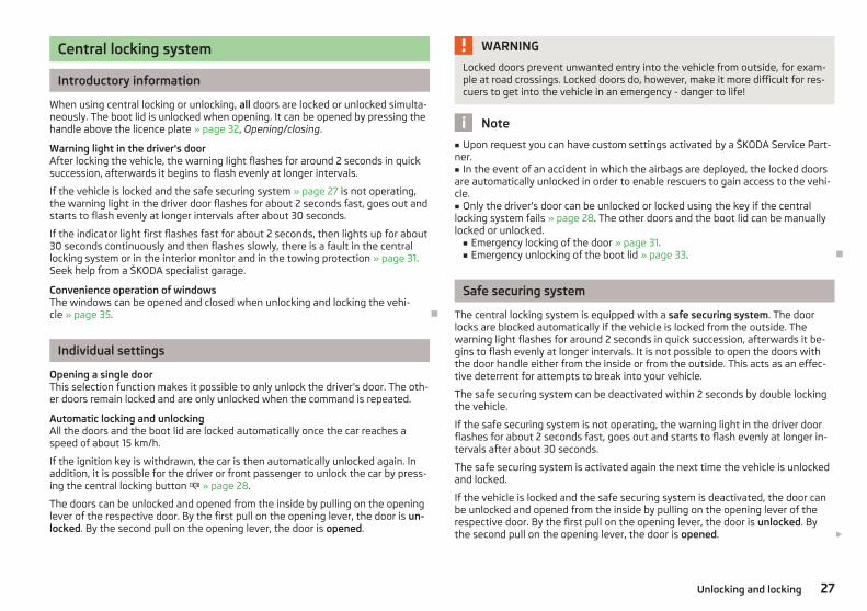
Central locking system
Introductory information
When using central locking or unlocking, all doors are locked or unlocked simulta-neously. The boot lid is unlocked when opening. It can be opened by pressing thehandle above the licence plate » page 32, Opening/closing.
Warning light in the driver's doorAfter locking the vehicle, the warning light flashes for around 2 seconds in quicksuccession, afterwards it begins to flash evenly at longer intervals.
If the vehicle is locked and the safe securing system » page 27 is not operating,the warning light in the driver door flashes for about 2 seconds fast, goes out andstarts to flash evenly at longer intervals after about 30 seconds.
If the indicator light first flashes fast for about 2 seconds, then lights up for about30 seconds continuously and then flashes slowly, there is a fault in the centrallocking system or in the interior monitor and in the towing protection » page 31.Seek help from a ŠKODA specialist garage.
Convenience operation of windowsThe windows can be opened and closed when unlocking and locking the vehi-cle » page 35. Ð
Individual settings
Opening a single doorThis selection function makes it possible to only unlock the driver's door. The oth-er doors remain locked and are only unlocked when the command is repeated.
Automatic locking and unlockingAll the doors and the boot lid are locked automatically once the car reaches aspeed of about 15 km/h.
If the ignition key is withdrawn, the car is then automatically unlocked again. Inaddition, it is possible for the driver or front passenger to unlock the car by press-ing the central locking button » page 28.
The doors can be unlocked and opened from the inside by pulling on the openinglever of the respective door. By the first pull on the opening lever, the door is un-locked. By the second pull on the opening lever, the door is opened.
WARNING
Locked doors prevent unwanted entry into the vehicle from outside, for exam-ple at road crossings. Locked doors do, however, make it more difficult for res-cuers to get into the vehicle in an emergency - danger to life!
Note
■ Upon request you can have custom settings activated by a ŠKODA Service Part-ner.■ In the event of an accident in which the airbags are deployed, the locked doorsare automatically unlocked in order to enable rescuers to gain access to the vehi-cle.■ Only the driver's door can be unlocked or locked using the key if the centrallocking system fails » page 28. The other doors and the boot lid can be manuallylocked or unlocked.■ Emergency locking of the door » page 31.■ Emergency unlocking of the boot lid » page 33. Ð
Safe securing system
The central locking system is equipped with a safe securing system. The doorlocks are blocked automatically if the vehicle is locked from the outside. Thewarning light flashes for around 2 seconds in quick succession, afterwards it be-gins to flash evenly at longer intervals. It is not possible to open the doors withthe door handle either from the inside or from the outside. This acts as an effec-tive deterrent for attempts to break into your vehicle.
The safe securing system can be deactivated within 2 seconds by double lockingthe vehicle.
If the safe securing system is not operating, the warning light in the driver doorflashes for about 2 seconds fast, goes out and starts to flash evenly at longer in-tervals after about 30 seconds.
The safe securing system is activated again the next time the vehicle is unlockedand locked.
If the vehicle is locked and the safe securing system is deactivated, the door canbe unlocked and opened from the inside by pulling on the opening lever of therespective door. By the first pull on the opening lever, the door is unlocked. Bythe second pull on the opening lever, the door is opened. £
27Unlocking and locking

WARNING
If the vehicle is locked from the outside and the safe securing system is acti-vated, there must not be any person in the vehicle as it is then no longer pos-sible to open either a door or a window from the inside. The locked doorsmake it more difficult for rescuers to get into the vehicle in an emergency -hazard!
Note
■ The anti-theft alarm system is activated when the vehicle is locked even if thesafe securing system is deactivated. The interior monitor is however not activa-ted.■ After locking the vehicle, you will be informed that the safe securing system isactivated by means of the message CHECK DEADLOCK on the instrument clusterdisplay. On vehicles that are equipped with an information display, the followingmessage will appear Check deadlock! Owner's manual! appears. Ð
Unlocking the vehicle using the key
Fig. 12 Turning the key for unlockingand locking the vehicle
› Turn the key in the locking cylinder of the driver's door in the direction of travel(unlocking position) A » Fig. 12.
› Pull the door handle and open the door.
› All the doors (only the driver's door on vehicles with anti-theft alarm system)are unlocked.
› The boot lid is then unlocked.› The switched on interior lights come on over the door contact.› The safe securing system is deactivated.
› The windows open while the key is held in the unlock position.› The warning light in the driver door stops flashing if the car is not fitted with an
anti-theft alarm system » page 30.
Note
If the vehicle is equipped with an anti-theft alarm system, you must insert the keyinto the ignition lock and switch the ignition on within 15 seconds after unlockingthe door in order to deactivate the anti-theft alarm system. The alarm is trig-gered if the ignition is not switched on within 15 seconds. Ð
Locking the vehicle with the key
› Turn the key in the locking cylinder of the driver's door in the opposite directionof travel (lock position) B » Fig. 12 on page 28.
› All the doors and the boot lid are locked.› The switched on interior lights will switch off over the door contact.› The windows close while the key is held in the lock position.› The safe securing system is immediately activated.› The warning light in the driver door begins flashing.
Note
If the driver's door has been opened, the vehicle cannot be locked. Ð
Vehicle locking/unlocking from the inside
Fig. 13 Centre console: Central lockingbutton
If the vehicle was not locked from the outside, you can also unlock and lock itwith the rocker switch » Fig. 13 without the ignition switched on. £
28 Using the system

Locking all doors and the boot lid› Press the button in the area » Fig. 13. The symbol in the button comes
on.
Unlocking all doors and the boot lid› Press the button in the area » Fig. 13. The symbol in the button is no lon-
ger illuminated.
The following applies if your vehicle has been locked using the central lockingbutton.
› It is not possible to open the doors or the boot lid from the outside (safety fea-ture, e.g. when stopping at traffic lights etc.).
› The doors can be unlocked and opened from the inside by pulling on the open-ing lever of the respective door. By the first pull on the opening lever, the dooris unlocked. By the second pull on the opening lever, the door is opened.
› If at least one door has been opened, the vehicle cannot be locked.› In the event of an accident in which the airbags are deployed, the locked doors
are automatically unlocked from the inside in order to enable rescuers to gainaccess to the vehicle.
WARNING
The central locking system also operates if the ignition is switched off. Chil-dren should never be left unattended in the vehicle since it is difficult to pro-vide assistance from the outside when the doors are locked. Locked doorsmake it difficult for rescuers to get into the vehicle in an emergency - hazard!
Note
If the safe securing system is activated» page 27, the door opening lever and thecentral locking buttons do not operate. Ð
Remote control
Introductory information
You can use the remote control key to:› unlock and lock the vehicle,› unlocking boot lid;› open and close the windows » page 35, Window convenience operation.
The transmitter with the battery is housed in the handle of the remote controlkey. The receiver is located in the interior of the vehicle. The operating range ofthe remote control key is approx. 30 m. But this range of the remote control canbe reduced if the batteries are weak.
The key has a fold-open key bit which can be used for unlocking and locking thecar manually and also for starting the engine.
If a lost key is replaced or if the receiver unit has been repaired or replaced, thesystem must be initialised by a ŠKODA Service Partner. Only then can the remotecontrol key be used again.
Note
■ The remote control is automatically deactivated when the ignition is switchedon.■ The operation of the remote control may temporarily be affected by interfer-ence from transmitters close to the car and which operate in the same frequencyrange (e.g. mobile phone, TV transmitter).■ The battery must be replaced if the central locking or anti-theft alarm systemdoes react to the remote control at less than 3 metres away » page 25.■ If the driver door is open, the vehicle cannot be locked using the remote controlkey. Ð
Unlocking/locking
Fig. 14 Remote control key
Unlocking the vehicle › Press the button 1 » Fig. 14.
Locking the vehicle › Press the button 3 » Fig. 14. £
29Unlocking and locking

Deactivating the safe securing system› Press the button 3 » Fig. 14 twice within 2 seconds. Further informa-
tion » page 27.
Unlocking the boot lid › Press the button 2 » Fig. 14. Further information » page 32.
Folding out the key bit› Press the button 4 » Fig. 14.
Folding in the key bit› Press the button 4 » Fig. 14 and fold in the key bit.
UnlockingThe turn signal lights flash twice as confirmation that the vehicle has been un-locked. If the vehicle is unlocked using button 1 and none of the doors or theboot lid are opened within the next 30 seconds, the vehicle is automaticallylocked again and the safe securing system or anti-theft alarm system is reactiva-ted. This function is intended to prevent the car being unlocked unintentionally.
In addition, when the car is unlocked, the electrically adjustable seats and exteri-or mirrors move into the position assigned to this key. The stored setting of driverseat and exterior mirrors is retrieved.
LockingThe turn signal lights flash once to confirm that the vehicle has been correctlylocked.
If the doors or the boot lid remain open after the vehicle has been locked, theturn signal lights do not flash until they have been closed.
WARNING
If the car is locked from the outside and the safe securing system is activated,there must not be any person in the car as it is then not possible to open ei-ther a door or a window from the inside. The locked doors make it more diffi-cult for rescuers to get into the vehicle in an emergency - hazard!
Note
■ Only operate the remote control when the doors and boot lid are closed and thevehicle is in your line of sight.■ To avoid the car being locked inadvertently once in the car, the lock button of the remote control must not be pressed before the key is inserted into the ig-nition lock. Should this happen, press the unlock button of the remote control. Ð
Synchronization
If the vehicle cannot be unlocked by actuating the remote control system then itis possible that the code in the key and the control unit in the vehicle are no lon-ger synchronised. This can occur when the buttons on the radio-operated key areactuated a number of times outside of the operative range of the equipment orthe battery on the remote control was replaced.
This means it is necessary to synchronise the code as follows:› press any button on the remote control key;› pressing of the button means that the door will unlock with the key within 1 mi-
nute. Ð
Anti-theft alarm system
Introductory information
The anti-theft alarm system increases the level of protection against peopleseeking to break into the vehicle. The system triggers audible and visual warningsignals if an attempt is made to break into the vehicle.
How is the alarm system activated?The anti-theft alarm system is activated when the vehicle is locked with the radioremote control or the key in the driver's door . It is activated 30 seconds afterlocking the door.
How is the alarm system deactivated?The alarm system is deactivated by pressing the unlock button on the radio re-mote control. The anti-theft alarm system is reactivated if the vehicle is notopened within 30 seconds after transmitting the radio signal.
If the vehicle is unlocked by inserting the key into the driver door, the key mustbe inserted into the ignition lock and the ignition switched on within 15 secondsof unlocking the door to deactivate the alarm system. The alarm is triggered ifthe ignition is not switched on within 15 seconds.
When is the alarm triggered?
The following security areas of the locked vehicle are monitored:› bonnet;› boot lid;› doors;› ignition lock; £
30 Using the system

› Vehicle inclination » page 31;› Interior of the vehicle » page 31;› A drop in voltage of the on-board power supply;› Socket of the factory-fitted towing device.
An alarm is immediately triggered if either of the two battery terminals is discon-nected while the anti-theft alarm system is activated.
How is the alarm switched off?The alarm is switched off by unlocking the vehicle with the radio remote controlor switching on the ignition.
Note
■ The working life of the alarm siren is 5 years.■ Before leaving the vehicle, check that all the doors and windows are closed inorder to ensure that the anti-theft alarm system is fully operational.■ Coding of the radio remote control and the receiver unit precludes the use ofthe radio remote control from other vehicles. Ð
Interior monitor and towing protection
Fig. 15 Button for interior monitor andtowing protection
The interior monitor detects movements inside the car and then triggers thealarm.
Switching off› Switch off the ignition.› Open the driver door.› Press the button » Fig. 15 in the driver's door.› Lock the vehicle within 30 seconds.
The interior monitor and the towing protection are switched on again automati-cally the next time the car is locked.
Note
■ Switch off the interior monitor and the towing protection if there is a possibilityof the alarm being triggered by movements from (e.g. children or animals) withinthe vehicle interior or if the vehicle has to be transported (e.g. by train or ship) ortowed.■ The opened glasses storage compartment reduces the effectiveness of the in-terior monitor. To ensure the full functionality of the interior monitor, the glassesstorage compartment must always be closed before locking the vehicle. Ð
Emergency locking of the doors
Fig. 16 Rear door: Emergency locking ofthe door
An emergency locking mechanism is located on the face side of the doors whichhave no locking cylinder, it is only visible after opening the door.
Locking› Remove the panel A » Fig. 16.› Insert the key into the opening under the panel and press the stopping lever B
as far as the stop toward the inside.› Replace the cover.
After closing the door, it no longer be opened from the outside. The door can beunlocked from the inside by pulling on the door handle again, and then openedfrom the outside. Ð
31Unlocking and locking

Boot lid
ä Introduction
This chapter contains information on the following subjects:
Opening/closing 32Automatic locking 32Emergency unlocking 33
WARNING
■ Ensure that the lock is properly engaged after closing the boot lid. Other-wise, the boot lid might open suddenly when driving even if the boot lid lockwas closed - risk of accident!■ Never drive with the boot lid fully opened or slightly ajar otherwise exhaustgases may get into the interior of the vehicle - risk of poisoning!■ Do not press on the rear window when closing the boot lid, it could crack -risk of injury!
Note
■ After closing the boot lid, it is automatically locked within 1 second and theanti-theft alarm system is activated. This applies only if the vehicle was lockedbefore closing the boot lid.■ The function of the handle above the licence plate is deactivated when startingoff or at a speed of 5 km/hour or more for vehicles with central locking. The func-tion of the handle is activated again when the vehicle has stopped and a door isopened. Ð
Opening/closing
Fig. 17 Unlock the boot lid/boot lid handle
First read and observe the introductory information and safety warn-ings on page 32.
After unlocking the vehicle, you can open the lid by pushing the handle locatedabove the licence plate.
Opening the boot lid for vehicles without central locking› Press the button in the driver's door » Fig. 17 - and open the boot lid in
the direction of arrow » Fig. 17 - .
Opening the boot lid for vehicles with central locking› Push the handle and lift the boot lid in the direction of the arrow » Fig. 17 - .
Closing› Pull down the boot lid and close it with a slight swing.
A handle which makes the closing easier is located on the inner panelling of theboot lid. Ð
Automatic locking
First read and observe the introductory information and safety warn-ings on page 32.
If the vehicle was locked with the button on the remote control key before theboot lid was closed, the lid is automatically locked as soon as it is closed. £
ä
ä
32 Using the system

The delayed automatic locking function of the boot lid can be activated on yourvehicle. The following applies following activation of this function: If the boot lidwas locked with the button on the remote control key 2 » page 29, then it ispossible to open the lid within a limited period of it being closed.
If you wish, a ŠKODA Service Partner can activate or deactivate the delayed auto-matic locking of the boot lid. The Service Partner will also provide any further in-formation that is required.
There is a risk of unwanted entry into the vehicle before the boot lid is locked au-tomatically. Always lock the vehicle using the button on the remote control orwith the key if no remote control is available » page 28. Ð
Emergency unlocking
Fig. 18 Emergency unlocking of the bootlid
First read and observe the introductory information and safety warn-ings on page 32.
The boot lid can be unlocked manually if there is a fault in the central locking sys-tem.
Unlocking› Fold the rear seat backrest forward » page 49.› Insert a screwdriver or similar tool into the opening in the trim in the direction
of the arrow 1 » Fig. 18 as far as the stop.› Unlock the lock 3 under the trim in the direction of arrow 2 .› Open the boot lid. Ð
ä
Electrical power windows
ä Introduction
This chapter contains information on the following subjects:
Opening/closing the windows 34Force limiter of the electrical power windows 34Window convenience operation 35Operational faults 35
WARNING
■ If the vehicle is locked from the outside, do not leave anybody in the vehicleas it is not possible to open the windows from the inside in the event of anemergency.■ The system is fitted with a force limiter » page 34. If there is an obstacle,the closing process is stopped and the window goes down by several centi-metres. The windows should nevertheless be closed carefully! Otherwisethese can cause severe crushing injuries!■ It is recommended to deactivate the electrical power windows in the reardoors (safety pushbutton) S » Fig. 19 on page 34 when children are beingtransported on the rear seats.
CAUTION
■ Keep the windows clean to ensure the correct functionality of the electric win-dows.■ In the event that the windows are frozen, first of all eliminate theice » page 130, De-icing windows and exterior mirrors and only then operate theelectrical power windows. Otherwise, the electrical power window mechanismcould be damaged.■ When leaving the locked vehicle make sure that the windows are closed at alltimes. £
33Unlocking and locking

Note
■ After switching the ignition off, it is still possible to open or close the windowsfor approx. 10 minutes. The electrical power windows are only switched off com-pletely once the driver's door or front passenger door are opened.■ When driving always use the existing heating, air conditioning and ventilationsystem for ventilating the interior of the vehicle. If the windows are opened, dustas well as other dirt can get into the vehicle and in addition the wind noise ismore at certain speeds.■ At high speeds, you should keep the windows closed to prevent unnecessarilyhigh fuel consumption. Ð
Opening/closing the windows
Fig. 19 Buttons on the driver's door/in the rear doors
First read and observe the introductory information and safety warn-ings on page 33.
The electrical power windows can only be operated when the ignition is switchedon.
Opening› A window is opened by pressing lightly on the respective button in the door.
The opening process stops when one releases the button.› Additionally, the window can be opened automatically (fully open) by pressing
the button to the stop. Renewed pressing of the button causes the window tostop immediately.
Closing› A window is closed through pulling lightly on the respective button in the door.
The closing process stops when one releases the button.
ä
› Additionally, the window can be closed automatically (fully closed) by pullingthe button to the stop. Renewed pulling of the button causes the window tostop immediately.
Buttons for the electrical power windows
Button for electrical power window of the driver's doorButton for electrical power window of the front passenger doorButton for electrical power window of the rear right doorButton for electrical power window of the rear left doorSafety pushbutton
Safety pushbuttonThe buttons for electrical power windows in the rear doors can be deactivated bypressing the safety pushbutton S » Fig. 19. The buttons for the electrical powerwindows in rear doors are activated again by pressing the safety pushbutton Sagain.
If the buttons for the rear doors are deactivated, the warning light in the safe-ty switch S lights up.
Note
The window lift mechanism is equipped with protection against overheating. Re-peated opening and closing of the window can cause this mechanism to over-heat. If this happens, it will not be possible to operate the window for a shorttime. You will be able to operate the window again as soon as the overheatingprotection has cooled down. Ð
Force limiter of the electrical power windows
First read and observe the introductory information and safety warn-ings on page 33.
The electrical power windows are fitted with a force limiter. It reduces the risk ofbruises or injuries when closing the windows.
If there is an obstacle, the closing process is stopped and the window goes downby several centimetres.
If the obstacle prevents the window from being closed during the next 10 sec-onds, the closing process is interrupted once again and the window goes down byseveral centimetres. £
A
B
C
D
S
ä
34 Using the system

If you attempt to close the window again within 10 seconds of the window beingmoved down for the second time, even though the obstacle was not yet been re-moved, the closing process is only stopped. During this time it is not possible toautomatically close the window. The force limiter is still switched on.
The force limiter is only switched off if you attempt to close the window againwithin the next 10 seconds - the window will now close with full force!
If you wait longer than 10 seconds, the force limiter is switched on again. Ð
Window convenience operation
First read and observe the introductory information and safety warn-ings on page 33.
The electrical power windows can be opened and closed as follows when unlock-ing and locking the vehicle.
Opening› Press and hold the unlock button on the remote control key.› Hold the key in the driver's lock in the unlock position.
Closing› Press and hold the lock button on the remote control key.› Hold the key in the driver's lock in the lock position.
You can interrupt the opening or closing process for the windows immediately byreleasing the key or the lock button. Ð
Operational faults
First read and observe the introductory information and safety warn-ings on page 33.
Electrical power windows do not operate
If the battery has been disconnected and then reconnected while the windowwas opened, the electrical power windows will not operate. The system must beactivated. Proceed as follows in order to re-establish the function:› switch on the ignition;› pull the top edge of the button in the driver's door to close the window;› release the button;› pull the relevant button upwards again for approx. 3 seconds.
ä
ä
Operation in winterIn the winter, ice accumulating on the surface of the window may cause there tobe more resistance when closing the window. The window will stop and moveback several centimetres.
It is necessary to deactivate the force limiter to close the window » page 34. Ð
Panorama roof
Fig. 20 Panorama roof: Open sun screen
The interior compartment can be brightened through the panorama roof out oftinted glass. The panorama roof can be exposed or covered over with the sunscreen » Fig. 20. In order to close the panorama roof completely, the sun screenmust be pushed into its end position.
Please pay attention to the following points if you wish to transport luggage orother items on the roof of your vehicle » page 59, in section Roof rail. Ð
35Unlocking and locking

Lights and visibility
Lights
ä Introduction
This chapter contains information on the following subjects:
Switching lights on and off 36DAY LIGHT function (Daylight driving light) 37Halogen projector headlights with cornering light function 37Parking light 37Tourist light 38Fog lights 38Fog lights with the function CORNER 38Rear fog light 39Headlight beam adjustment 39Switches for the hazard warning light system 40Turn signal and main beam lever 40
On models fitted with right-hand steering the position of certain switches differsfrom that shown in » Fig. 21 on page 36. The symbols which mark the switch po-sitions are identical, however.
WARNING
Never drive with only the side lights on! The side lights are not bright enoughto light up the road sufficiently in front of you or to be seen by other oncom-ing traffic. Therefore always switch on the low beam when it is dark or if visi-bility is poor.
CAUTION
■ The activation of the lights should only be undertaken in accordance with na-tional legal requirements.■ The driver is always responsible for the correct settings and use of the lights.
Note
■ If the light switch is in the position , the ignition key is removed and the driv-er's door is open, an audible warning signal will sound. The audible warning signalis switched off by means of the door contact when the driver's door is closed (ig-nition off), however, the side lights remain on to illuminate the parked vehicle ifnecessary.■ In the event of cool or humid weather conditions, the headlights can be mistedup from inside. The temperature difference between interior and external area ofthe headlight lenses is decisive. When the driving lights are switched on, the lightoutlet surfaces are free from mist after a short period, although the headlightlenses may still be misted up in the peripheral areas. It also concerns reverse lightand turn signal lights. This mist has no influence on the life of the lighting system. Ð
Switching lights on and off
Fig. 21 Dash panel: Light switch/fuse box: Switch for daylight driving lights
First read and observe the introductory information and safety warn-ings on page 36.
Switching on the parking light› Turn the light switch » Fig. 21 - to position .
Switching on the low beam and main beam› Turn the light switch » Fig. 21 - to position .› Press the main beam lever forward in order to switch on the main
beam » Fig. 25 on page 40.
Switching off lights (except daytime running lights)› Turn the light switch » Fig. 21 - to position O. Ð
ä
36 Using the system

DAY LIGHT function (Daylight driving light)
First read and observe the introductory information and safety warn-ings on page 36.
Switching on› Remove the cover on the fuse box on the left-hand side of the dash pan-
el » page 167, Fuses in the dash panel.› Turn the light switch into position O » Fig. 21 on page 36 - .› Switch on the switch for daylight driving lights » Fig. 21 on page 36 - .
Switching off› Remove the cover on the fuse box on the left-hand side of the dash pan-
el » page 167, Fuses in the dash panel.› Switch off the switch for daylight driving lights » Fig. 21 on page 36 - .› Turn the light switch to the position Parking light or Low beam » Fig. 21
on page 36 - .
Activating daylight driving lights for vehicles with the START-STOP system› Switch off the ignition.› At the same time, slide the turn signal light lever upwards and hold it in this po-
sition for at least 3 seconds.› Switch on the ignition - wait until the right-turn signal light flashes 4x.› Switch off the ignition - an audible signal sounds which confirms the activation
of the daylight driving lights.› Release the turn signal lever.
Deactivating daylight driving lights for vehicles with the START-STOP system› Switch off the ignition.› At the same time, slide the turn signal light lever downwards and hold it in this
position for at least 3 seconds.› Switch on the ignition - wait until the left-turn signal light flashes 4x.› Switch off the ignition - an audible signal sounds which confirms the deactiva-
tion of the daylight driving lights.› Release the turn signal lever.
On vehicles with separate lights for daylight driving lights in the fog lights or inthe front bumper, the parking lights and the licence plate light do not come onwhen activating the function daylight driving lights (neither front nor rear).
If the vehicle is not equipped with separate lights for daylight driving lights, thecombination of the low beam, the parking lights (front and rear) including the li-cence plate light is used as daylight driving lights. Ð
ä
Halogen projector headlights with cornering light function
First read and observe the introductory information and safety warn-ings on page 36.
For a better cornering illumination, the halogen projector headlights with corner-ing light function are set in the optimal position in line with the vehicle speed andthe steering angle.
WARNING
If the halogen projector headlights with cornering light function are faulty, theheadlights are automatically lowered to the emergency position, which pre-vents a possible dazzling of oncoming traffic. Thus the illuminated length ofthe road is shortened. Drive carefully and visit a ŠKODA specialist garage assoon as possible. Ð
Parking light
First read and observe the introductory information and safety warn-ings on page 36.
Parking light › Switch off the ignition.› Pull the turn signal light lever » Fig. 25 on page 40 » page 40 upwards or
downwards - the side light on the right or left side of the vehicle is switched.
Parking light on both sides› Turn the light switch into the position and lock the vehicle.
Note
■ The parking light can only be activated if the ignition is switched off.■ If the right or left turn signal light has been switched on and the ignition isswitched off, the parking light is not automatically switched on. Ð
ä
ä
37Lights and visibility

Tourist light
First read and observe the introductory information and safety warn-ings on page 36.
Halogen projector headlights with cornering light functionThis mode makes it possible to drive in countries with opposing traffic system(driving on the left/right) without dazzling the oncoming vehicles. When the mode“tourist light” is active, the side to side swivel of the headlights is deactivated.
Activating tourist lightBefore activating the tourist light, the following conditions must be met.
Ignition switched off, light switched off (light switch in the position O), control dialfor the headlamp beam adjustment in the position -, no gear engaged or selectorlever in the position N (automatic gearbox), tourist light deactivated.› Switch on the ignition.
within 10 seconds of the ignition being switched on:› Turn the light switch to position » page 36, Switching lights on and off.› Engage reverse gear (manual gearbox) or move the selector lever into the posi-
tion R (automatic gearbox),› Turn the control dial for headlamp beam adjustment from the position - to the
position 3 » page 39.
Deactivating tourist lightBefore deactivating the tourist light, the following conditions must be met.
Ignition switched off, light switched off (light switch in the position O), control dialfor the headlamp beam adjustment in the position 3, no gear engaged or selectorlever in the position N (automatic gearbox), tourist light activated.› Switch on the ignition.
within 10 seconds of the ignition being switched on:› Turn the light switch to position » page 36, Switching lights on and off.› Engage reverse gear (manual gearbox) or move the selector lever into the posi-
tion R (automatic gearbox),› Turn the control dial for headlamp beam adjustment from the position 3 to the
position - » page 39.
Further information » page 123, Headlights.
ä
Note
When the “tourist light” mode is active, the warning light flashes for 10 sec-onds each time the ignition is switched on. Ð
Fog lights
Fig. 22 Dash panel: Light switch
First read and observe the introductory information and safety warn-ings on page 36.
Switching on› First of all, turn the light switch » Fig. 22 to position or .› Pull the light switch to position 1 .
The warning light lights up in the instrument cluster when the fog lights areswitched on » page 17. Ð
Fog lights with the function CORNER
First read and observe the introductory information and safety warn-ings on page 36.
The fog lights with the function CORNER are designed to improve the illuminationof the surrounding area near the vehicle when turning, parking, etc. £
ä
ä
38 Using the system

The fog lights with the function CORNER are adjusted according to the steeringangle or after switching on the turn signal light 1) in the following circumstances:› the vehicle is stationary and the engine is running or it moves with a speed of
maximum 40 km/h;› the daytime running lights are not switched on;› the low beam is switched on;› the fog lights are not switched on;› no reverse gear is engaged. Ð
Rear fog light
First read and observe the introductory information and safety warn-ings on page 36.
Switching on› First of all, turn the light switch » Fig. 22 on page 38 » page 38 to position or.
› Pull the light switch to position 2 .
If the vehicle is not fitted with fog lights » page 38, the rear fog light is switchedon by turning the light switch to the position or and is pulled out directly tothe position 2 . This switch does not have two positions, but only one position.
The warning light lights up in the instrument cluster when the rear fog light isswitched on » page 17.
Only the rear fog light on the trailer lights up if the vehicle has a factory-fittedtowing device or a towing device from ŠKODA original accessories and it is drivenwith a trailer and the rear fog light switched on. Ð
ä
Headlight beam adjustment
Fig. 23 Dash panel: Lights and visibility
First read and observe the introductory information and safety warn-ings on page 36.
› Turn the control dial » Fig. 23 to the desired width of illumination.
Settings
The positions correspond approximately to the following car load.Front seats occupied, boot empty.All seats occupied, boot empty.All seats occupied, boot loaded.Driver seat occupied, boot loaded.
CAUTION
Always adjust the headlight range adjustment in such a way that:■ it does not dazzle other road users, especially oncoming traffic;■ and the range is sufficient for safe driving.
Note
We recommend you adjust the headlight beam when the low beam is switchedon. Ð
ä
-
1
2
3
1) If both switch on versions are conflicting, for example if the steering wheel is turned to the left andthe right turn signal light is switched on, the turn signal light has the higher priority.
39Lights and visibility
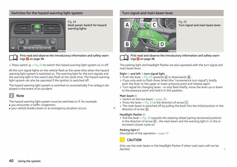
Switches for the hazard warning light system
Fig. 24 Dash panel: Switch for hazardwarning lights
First read and observe the introductory information and safety warn-ings on page 36.
› Press switch » Fig. 24 to switch the hazard warning light system on or off.
All the turn signal lights on the vehicle flash at the same time when the hazardwarning light system is switched on. The warning light for the turn signals andthe warning light in the switch also flash at the same time. The hazard warninglight system can also be operated if the ignition is switched off.
The hazard warning light system is switched on automatically if an airbag is de-ployed in the event of an accident.
Note
The hazard warning light system must be switched on if, for example:■ you encounter a traffic congestion;■ your vehicle breaks down or an emergency situation occurs. Ð
ä
Turn signal and main beam lever
Fig. 25 Turn signal and main beam lever
First read and observe the introductory information and safety warn-ings on page 36.
The parking light and headlight flasher are also operated with the turn signal andmain beam lever.
Right and left turn signal light› Push the lever » Fig. 25 upwards A or downwards B .› If you only wish to flash three times (the "convenience turn signal"), briefly
push the lever to the upper or lower pressure point and release again.› Turn signal for changing lanes - to only flash briefly, move the lever up or down
to the pressure point and hold it in this position.
Main beam › Switch on the low beam » page 36.› Press the lever » Fig. 25 in the direction of arrow C .› The main beam is switched off by pulling the lever into the initial position in the
direction of arrow D .
Headlight flasher › Pull the lever » Fig. 25 towards the steering wheel (spring-tensioned position)
in the direction of arrow D - the main beam and the warning light in the in-strument cluster come on.
Parking light Description of the operation » page 37
CAUTION
Only use the main beam or the headlight flasher if other road users will not bedazzled. £
ä
40 Using the system

Note
■ The turn signal system only operates when the ignition is switched on. The cor-responding warning light or in the instrument cluster also flashes.■ The turn signal is automatically cancelled after negotiating a curve.■ The warning light flashes at twice its normal rate if a bulb for the turn signallight fails. Ð
Interior light
Interior lights at the front
Fig. 26 Interior lights at the front
Door contact switching mechanism (front and rear doors)› Press switch A » Fig. 26 towards the middle of the light, the symbol ap-
pears.
Switching the interior light on› Press switch A » Fig. 26 towards the edge of the light, the symbol appears.
Switching the interior light off› Press the switch A » Fig. 26 in the middle position O.
Reading lights› Press the switches B » Fig. 26 in order to switch the right or left reading light
on or off.
On vehicles with central locking, the interior light is switched on for about 30 sec-onds when the vehicle is unlocked, when a door is opened or after withdrawingthe ignition key (if the relevant switch is in the door contact position). The innerlight goes out out immediately after the ignition is switched on.
A time delay switch causes the inner lighting on vehicles without a central lockingsystem stays on for a few seconds after the doors have been closed. The innerlight goes out out immediately after the ignition is switched on.
The interior lighting is switched off after about 10 minutes when a door has beenleft open in order to avoid discharging the battery of the vehicle. Ð
Interior lights at the rear
Fig. 27 Interior lights at the rear
The interior lighting » Fig. 27 is actuated by moving the switch to the symbol , Oor to the middle position .
The same principles apply for the interior lighting as for » page 41, Interior lightsat the front. Ð
Illuminated storage compartment on front passenger side
› When opening the flap of the storage compartment on the front passengerside the lighting in the storage compartment comes on.
› The light switches on automatically when the parking light is switched on andgoes out when the flap is closed. Ð
Boot light
The light comes on automatically when the boot lid is opened. If the lid remainsopen for more than about 10 minutes, the boot light switches off automatically. Ð
41Lights and visibility

Visibility
Rear window heater
Fig. 28 Switch for rear window heater
› The rear window heater is switched on or off by pressing the switch » Fig. 28 the warning light in the switch comes on or goes out.
The rear window heater only operates when the engine is running.
The rear window heater switches off automatically after 7 minutes.
For the sake of the environment
The heating should be switched off as soon as the window is de-iced or free frommist. The reduced current consumption will have a favourable effect on fuel econ-omy » page 122, Saving electricity.
Note
If the on-board voltage drops, the rear window heater switches off automatically,in order to provide sufficient electrical energy for the engine control » page 147,Automatic load deactivation. Ð
Sun visors
Fig. 29 Sun visor: swivelling out
The sun visor for the driver or front passenger can be pulled out of the fixture andswivelled towards the door in the direction of the arrow 1 » Fig. 29.
The vanity mirrors in the sun visors are provided with covers. Push the cover inthe direction of the arrow 2 .
The purpose of the strap A is to store small, light objects, such as a notepad, etc.
WARNING
The sun visors must not be swivelled towards the side windows in the deploy-ment area of the head airbags if any objects, such as ball-point pens, etc. areattached to them. This might result in injuries to the occupants if the head air-bag is deployed. Ð
Windscreen wipers and washers
ä Introduction
This chapter contains information on the following subjects:
Activating the windscreen wipers and washers 43Headlight cleaning system 44Replacing the windscreen wiper blades 44Replacing the rear window wiper blade 44
The windshield wipers and the windshield washer system only operate if the igni-tion is switched on. £
42 Using the system

The rear window is wiped once if the windscreen wipers are on when reversegear is selected.
Top up with windscreen wiper fluid » page 143.
WARNING
■ Properly maintained windscreen wiper blades are essential for clear visibilityand safe driving » page 44.■ Do not use the windscreen washer system at low temperatures, withoutheating the windscreen beforehand. Otherwise the window cleaner couldfreeze on the windscreen and restrict the view to the front.
CAUTION
■ In cold temperatures and during the winter, check before the journey or beforeswitching on the ignition that the wiper blades are not frozen to the windscreen.If the windscreen wipers are switched on when the blades are frozen to thewindscreen, this may damage both the blades and windscreen wiper motor!■ If the ignition is switched off while the windscreen wipers are switched on, thewindscreen wipers will continue wiping in the same mode after the ignition isturned back on. The windscreen wipers could freeze up in cold temperatures be-tween the time the ignition was turned off and when it was turned back on again.■ Carefully detach frozen wiper blades from the front or rear window.■ Remove snow and ice from the windscreen wipers before driving.■ If the windscreen wipers are handled carelessly, there is a risk of damage to thewindscreen.■ Replace the windscreen wiper blades once or twice a year for safety reasons.These can be purchased from a ŠKODA Service Partner.
Note
■ The windscreen washer nozzles for the windscreen are heated when the en-gine is running and the outside temperature is less than approx. +10 °C.■ The content of the windscreen washer fluid reservoir is 3.5 litres. On vehiclesfitted with the headlight cleaning system, the volume is around 5.4 litres.■ The wiper blades should be cleaned on a regular basis with a windscreen clean-er to avoid any smears. The wiper blades should be cleaned with a sponge orcloth if they are heavily soiled by insect residues, for example. Ð
Activating the windscreen wipers and washers
Fig. 30 Windscreen wiper lever
First read and observe the introductory information and safety warn-ings on page 42.
Flick wipe› If you only wish to wipe the windscreen briefly, push the lever into the spring-
tensioned position 4 » Fig. 30.
Periodic wiping› Position the lever upwards into position 1 » Fig. 30.› Set the desired break between the individual wiper strokes with the switch A .
Slow wipe› Position the lever upwards into position 2 » Fig. 30.
Fast wipe› Position the lever upwards into position 3 » Fig. 30.
Automatic wipe/wash for windscreen› Pull the lever towards the steering wheel into the spring-tensioned position
5 » Fig. 30, the wash system and the windshield wipers will operate.› Release the lever. The windscreen wash system stops and the wiper continues
for another 1 - 3 wiper strokes (depending on the period of spraying of thewindscreen).
Wiping the rear window pane› Push the lever away from the steering wheel into position 6 » Fig. 30 and the
windscreen wiper will operate every 6 seconds.
Automatic wipe/wash for the rear window› Push the lever away from the steering wheel into the spring-tensioned position
7 » Fig. 30, the windshield wiper and wash system will operate. £
ä
43Lights and visibility

› Release the lever. The washer system stops and the wiper continues for anoth-er 1 to 3 wiper strokes (depending on the duration of the spraying process). Thelever will stay in position after releasing it 6 .
Switching windscreen wipers off› Move the lever back into the home position 0 » Fig. 30. Ð
Headlight cleaning system
First read and observe the introductory information and safety warn-ings on page 42.
When the low beam or main beam are switched on, and the windscreen wiperlever is pulled into the position 5 » Fig. 30 on page 43, the headlights aresprayed briefly. To clean the headlights, the windshield is also sprayed after everyfive squirts.
You should remove stubborn dirt (such as insect residues) from the headlight len-ses at regular intervals, for example when refuelling. The following guidelinesmust be observed » page 130, Headlight lenses.
To ensure the proper operation of the cleaning system during the winter, anysnow should be removed from the washer nozzle fixtures and ice should becleared with a de-icing spray.
CAUTION
Never remove the nozzles from the headlight cleaning system by hand - risk ofdamage! Ð
Replacing the windscreen wiper blades
Fig. 31 Windscreen wiper blade
ä
First read and observe the introductory information and safety warn-ings on page 42.
Removing the wiper blade› Fold the windscreen wiper arm away from the windscreen.› Press the locking button 1 » Fig. 31 to unlock the wiper blade and pull off in
the direction of the arrow 2 .
Attaching the wiper blade› Push the windscreen wiper blade until the stop and it locks in place.› Check that the wiper blade is correctly attached.› Fold the wiper arms back to the windscreen.
Windshield wiper blades in proper condition are essential to obtain good visibility.Wiper blades should not be allowed to become dirtied by dust, insect remains andpreserving wax.
Juddering or smearing of the wiper blades could then be due to wax residues lefton the windshield by vehicle washing in automatic vehicle wash systems. It istherefore important to clean and degrease the lips of the windshield wiper bladesafter every pass through the automatic vehicle wash system. Ð
Replacing the rear window wiper blade
Fig. 32 Rear window wiper blade
First read and observe the introductory information and safety warn-ings on page 42.
Removing the wiper blade› Fold the windscreen wiper arm away from the windscreen and position the
wiper blade at a right angle to the wiper arm » Fig. 32.› Hold the windscreen wiper arm at the top end with one hand. £
ä
ä
44 Using the system

› With the other hand unlock the locking button A in the direction of arrow andremove the wiper blade.
Attaching the wiper blade› Position the wiper blade onto the wiper arm and lock the locking but-
ton A » Fig. 32.› Check that the wiper blade is correctly attached.› Fold the wiper arm back to the windscreen. Ð
Rear window
Manual dimming interior mirror
Basic setting› Pull the lever on the bottom edge of the mirror forward.
Dimming mirror› Push the lever on the bottom edge of the mirror backwards. Ð
Additional rear-view mirror
Fig. 33 Additional interior mirror
The additional interior mirror allows the driver a wider field of view of the rearseats.
Adjusting the angle› Adjust the mirror in direction of arrow to the desired position.
WARNING
Concentrate fully at all times on your driving! As the driver you are fully re-sponsible for the operation of your vehicle. Use the additional interior mirroronly to such an extent that you are in full control of your vehicle at any time. Ð
Exterior mirror
Fig. 34 Inner part of door: Rotary knob
Adjust the rear mirror before commencing to drive so that there is a clear view tothe rear.
Heating of the external mirror› Place the rotary knob into the position » Fig. 34.
The exterior mirror heater only operates when the engine is running and up to anoutside temperature of +20 °C.
Adjusting the left-hand exterior mirror› Place the rotary knob into the position » Fig. 34. The movement of the mirror
surface is identical to the movement of the rotary knob.
Adjusting the right-hand exterior mirror› Place the rotary knob into the position » Fig. 34. The movement of the mirror
surface is identical to the movement of the rotary knob. £
45Lights and visibility

WARNING
■ Convex (curved outward) exterior mirrors increase the field of vision. Theydo, however, make objects appear smaller in the mirror. These mirrors aretherefore only of limited use for estimating distances to the following vehi-cles.■ Whenever possible use the interior mirror for estimating the distances tothe following vehicles.
Note
■ Do not touch the surface of the exterior mirrors if the exterior mirror heater isswitched on.■ If the power setting function fails at any time, the exterior mirrors can be set byhand by pressing on the edge of the mirror surface.■ Contact your ŠKODA specialist garage if there is a fault with the power settingof the exterior mirrors. Ð
46 Using the system

Seats and Stowage
Front seats
ä Introduction
This chapter contains information on the following subjects:
Adjusting the front seats 47Front seat heating 48
The driver's seat should be adjusted in such a way that the pedals can be fullypressed to the floor with slightly bent legs.
The seat backrest on the driver's seat should be adjusted in such a way that theupper point of the steering wheel can be easily reached with slightly bent arms.
Correct adjustment of the seats is particularly important for:› safely and quickly reaching the controls;› a relaxed, fatigue-free body position;› achieving the maximum protection offered by the seat belts and the airbag
system.
WARNING
■ Only adjust the driver's seat when the vehicle is stationary - risk of accident!■ Caution when adjusting the seat! You may suffer injuries or bruises as a re-sult of adjusting the seat without paying proper attention.■ The seat backrests must not be angled too far back when driving otherwisethis will affect proper operation of the seat belts and of the airbag system -risk of injury!■ Never carry more people than the number of seats in the vehicle.■ Each occupant must correctly fasten the seat belt belonging to the seat.Children must be fastened » page 115, Transporting children safely with asuitable restraint system.■ The front seats and the head restraints must always be adjusted to matchthe body size of the seat occupant as well as the seat belts must always becorrectly fastened in order to provide an optimal protection for you and youroccupants.
WARNING (Continued)
■ Always keep your feet in the footwell when the car is being driven - neverplace your feet on the instrument panel, out of the window or on the surfacesof the seats. This is particularly important for the front seat passenger. Youwill be exposed to increased risk of injury if it becomes necessary to apply thebrake or in the event of an accident. If an airbag is deployed, you may sufferfatal injuries when adopting an incorrect seated position!■ It is important for the driver and front passenger to maintain a distance of atleast 25 cm from the steering wheel or dash panel. Not maintaining this mini-mum distance will mean that the airbag system will not be able to properlyprotect you - hazard!■ Ensure that there are no objects in the footwell as they may get caught be-hind the pedals when driving or applying the braking. You would then no lon-ger be able to operate the clutch, brake or accelerate.■ Do not transport any objects on the front passenger seat except objects(e.g. child safety seat) provided for this purpose - risk of accident!
Note
After a certain time, play can develop within the adjustment mechanism of thebackrest angle. Ð
Adjusting the front seats
Fig. 35 Control elements at the seat
First read and observe the introductory information and safety warn-ings on page 47.
Adjusting a seat in a forward/back direction› Pull the lever 1 » Fig. 35 up and push the seat into the desired position.› Release the lever 1 and push the seat until the lock clicks into place. £
ä
47Seats and Stowage

Adjusting height of seat› To lift the seat, pull or pump the lever 2 » Fig. 35 upwards.› To lower the seat, push or pump the lever 2 downwards.
Adjusting the angle of the seat backrest› To adjust the angle of the backrest, relieve any pressure from the seat backrest
(do not lean on it) and turn the handwheel 3 » Fig. 35. Ð
Front seat heating
Fig. 36 Rocker switch for front seatheating
First read and observe the introductory information and safety warn-ings on page 47.
The seat backrests and seats can be heated electrically.› By pressing the rocker switch in the position 1 or 2 switch on the front seat
heating to 25 % or 100 % of its power output » Fig. 36.› To switch off the heating shift the rocker switch into the horizontal position.
WARNING
If, as an occupant, you have a subdued pain and/or temperature sensitivity,e.g. through medication, paralysis or because of chronic illness (e.g. diabetes),we recommend not to use the seat heating. This can lead to burns on theback, the posterior and the legs which are difficult to heal. If the seat heatingis used, we recommend to make regular breaks in your journey when drivinglong distances, so that the body can recuperate from the stress of the jour-ney. Please consult your doctor, who can evaluate your specific condition.
ä
CAUTION
■ Do not kneel on the seats or otherwise apply pressure at specific points toavoid damaging the heating elements for the seat heaters.■ Do not use the seat heaters if the seats are not occupied by persons or if ob-jects, such as a child seat, bag, etc., are fastened or stored on them. A fault of theheating elements in the seat heating can occur.■ Do not clean the seats using moisture » page 132, Fabric covers on electricallyheated seats.
Note
■ The seat heating should only be switched on when the engine is running. Thishas a significant effect of saving on the battery capacity.■ If the on-board voltage drops, the seat heating is switched off automatically, inorder to provide sufficient electrical energy for the engine control » page 147,Automatic load deactivation. Ð
Head restraints
Fig. 37 Head restraint: adjusting/removing
Setting height› Grasp the side of the head restraint with both hands and push it upwards as
required » Fig. 37 - .› To move the head restraint downwards, press and hold the safety but-
ton » Fig. 37 - with one hand and press the head restraint downwards withthe other hand.
Removing/installing› Pull the head restraint out of the seat backrest as far as the stop. £
48 Using the system

› Press the locking button in direction of the arrow » Fig. 37 - and pull thehead restraint out.
› To re-insert the head restraint, push it far enough down into the seat backrestuntil the locking button clicks into place.
Best protection is achieved if the top edge of the head restraint is at the samelevel as the upper part of your head.
The head restraints must be adjusted to match the size of the seat occupant. Cor-rectly adjusted head restraints together with the seat belts offer effective protec-tion for the occupants » page 101.
WARNING
■ The head restraints must be correctly adjusted in order to offer effectiveprotection for the occupants in the event of an accident.■ Never drive with the head restraints removed - risk of injury!■ If the rear seats are occupied, the rear head restraint must not be in thelower position. Ð
Rear seats
Adjusting seats in forward/back direction
Fig. 38 Releasing at the front/rear
› Pull the lever A » Fig. 38 up in the direction of arrow 1 or on the release loopin direction of arrow 2 and move the seat into the desired position 3 .
WARNING
The following guidelines must be observed » page 102, Correct seated posi-tion for the occupants on the rear seats. Ð
Adjusting the angle of the seat backrest
Fig. 39 Adjusting the seat backrest
› Pull the lever 1 » Fig. 39 and adjust the required inclination of the seat back-rest.
WARNING
Check for yourself that the seat backrest is engaged by pulling on it. Ð
Folding the seat backrest forwards and folding the seat fullyforwards
Fig. 40 Fold seat fully forwards/lock folded forward seats £
49Seats and Stowage

Folding the seat backrest forwards› Put the belt tongue into the opening on the respective side of the vehicle -
safety position.› Remove the head restraint from the rear middle seat » page 48, Head re-
straints.› Push the outer rear seats towards the rear as far as they will go » page 49,
Adjusting seats in forward/back direction.› Pull the lever 1 » Fig. 39 on page 49 and fold the seat backrest completely for-
wards.› Pull the lever » Fig. 40 up before folding the seat forwards fully.
Folding seats fully forwards and locking them› If the outer rear seat is fully folded forward, push it towards the rear as far as it
can go.› Pull the lever A » Fig. 40 up and fold the seat forwards fully.› Secure the folded forward seat with the aid of the fixing belt B to a guide rod
of the head restraint for the front seat » Fig. 40.
WARNING
■ Immediately lock the folded forward seat with the aid of the fixing belt to aguide rod of the head restraint for the front seat - risk of injury.■ The following guidelines must be observed » page 102, Correct seated posi-tion for the occupants on the rear seats.
CAUTION
If the outer seat is not in the rear end position when folding forward, damage canoccur to the locking bolts when unlocking the seat. Ð
Unlocking and removing seats
Fig. 41 Unlocking the folded forward seat/carrying handles on the seatcushion
› Fold the seat forward » page 49, Folding the seat backrest forwards and fold-ing the seat fully forwards.
› Unlock the folded forward seat by pressing the seat locks A » Fig. 41 in direc-tion of arrow 1 .
› Remove the seat using the carrying handles B or C .
WARNING
The following guidelines must be observed » page 102.
Note
The outer seats are not mutually interchangeable. In the rear area the left seat ismarked with the letter L and the right seat with the letter R. Ð
50 Using the system

Adjusting seats in crosswise direction
Fig. 42 Locking seats
› Remove the middle seat » page 50, Unlocking and removing seats.› Fold the outer seat forward » page 49, Folding the seat backrest forwards and
folding the seat fully forwards and unlock » Fig. 41 on page 50.› Move the folded forward and unlocked seat on the guide towards the middle of
the vehicle up to the stop.› Lock the folded forward seat by pressing the seat locks A » Fig. 42 in the di-
rection of arrow. Ð
Move seats into the initial position
Fig. 43 Folding the seat backrest backinto position
› If the seat is removed, first of all position it on the guide and lock theseat » Fig. 42 on page 51. Pull the seat upwards to ensure that the seat islocked correctly.
› Fold the seat in the horizontal position until it can be heard to click. Check foryourself that the seat can no longer be lifted by pulling it up.
› Press the lever » Fig. 43 and fold back the seat backrest. Check for yourself thatthe seat backrest is engaged by pulling on it.
› Remove the tongue of the lock from the safety position.
WARNING
■ The belt locks must be in their original position after folding back the seatcushions and backrests - they must be ready to use.■ The seat backrests must be securely interlocked in position so that no ob-jects in the luggage compartment can slide into the passenger compartment ifthere is sudden braking - risk of injury!■ When folding the seat backrest always make sure that it has safely lockedinto position, this is confirmed by the position and a visible marking on thecover of the lever. Ð
Boot
ä Introduction
This chapter contains information on the following subjects:
Class N1 vehicles 52Fastening elements 52Folding hooks 53Fixing nets 53Fixing floor covering of the luggage compartment 53Boot cover 53Net partition 54
Please observe the following for the purpose of maintaining good handling char-acteristics of your vehicle:› Distribute loads as evenly as possible.› Place heavy objects as far forward as possible.› Attach the items of luggage to the lashing eyes or using the fixing
net » page 52.
In the event of an accident, there is such a high kinetic energy which is producedby small and light objects that they can cause severe injuries. The magnitude ofthe kinetic energy is dependent on the speed at which the vehicle is travellingand the weight of the object. The speed at which the vehicle is travelling is in thiscase the more significant factor. £
51Seats and Stowage

Example: In the event of a frontal collision at a speed of 50 km/h, an unsecuredobject with a weight of 4.5 kg produces an energy, which corresponds to 20 timesits own weight. This means that it results in a weight of approx. 90 kg “ ”. You canimagine the injuries that can occur, if this “object” flies through the interior com-partment and hits an occupant.
WARNING
■ Store the objects in the boot and attach them to the lashing eyes.■ Loose objects in the passenger compartment can be thrown forward duringa sudden manoeuvre or in case of an accident and can injure the occupants orother oncoming traffic. This risk is still increased, if the objects which are fly-ing around are hit by a deployed airbag. In this case, the objects which arethrown back can injure the occupants - hazard.■ Please note that the handling properties of the vehicle may be affectedwhen transporting heavy objects as the centre of gravity can be displaced -risk of accident! The speed and style of driving must be adjusted accordingly.■ If the items of luggage or objects are attached to the lashing eyes with un-suitable or damaged lashing straps, injuries can occur in the event of brakingmanoeuvres or accidents. To prevent items of luggage from being thrown for-ward, always use suitable lashing straps which must be firmly attached to thelashing eyes.■ The items carried in the boot must be stored in such a way that no objectsare able to slip forward if any sudden driving or braking manoeuvres are un-dertaken - risk of injury!■ When transporting fastened objects which are sharp and dangerous in theboot that has been enlarged by folding the rear seats forward, ensure thesafety of the passengers transported on the other rear seats » page 102, Cor-rect seated position for the occupants on the rear seats.■ If the rear seat next to the folded forward seat is occupied, ensure maxi-mum safety, e.g. by placing the goods to be transported in such a way that theseat is prevented from folding back in case of a rear collision.■ Never drive with the boot lid fully opened or slightly ajar otherwise exhaustgases may get into the interior of the vehicle - risk of poisoning!■ Under no circumstances, should the permissible axle loads and permissiblegross weight of the vehicle be exceeded - risk of accident!■ Never transport people in the boot!
CAUTION
Please ensure that the heating elements for the rear window heater are not dam-aged as a result of abrasive objects.
Note
Tyre pressure must be adjusted to the load » page 149, Service life of tyres. Ð
Class N1 vehicles
First read and observe the introductory information and safety warn-ings on page 51.
On class N1 vehicles, which are not fitted with a protective grille, a lashing setwhich complies with the standard EN 12195 (1 - 4) must be used for fastening theload. Ð
Fastening elements
Fig. 44 Boot: Lashing eyes and fasten-ing elements
First read and observe the introductory information and safety warn-ings on page 51.
The boot provides the following fastening elements » Fig. 44.
Lashing eyes for fastening items of luggage and fixing nets.Fastening elements for fastening fixing nets.
CAUTION
The maximum permissible load of the lashing eyes is 3.5 kN (350 kg). Ð
ä
ä
A
B
52 Using the system

Folding hooks
Fig. 45 Boot: folding hooks
First read and observe the introductory information and safety warn-ings on page 51.
Folding hooks » Fig. 45 for attaching small items of luggage, such as bags etc., areprovided on both sides of the luggage compartment.
CAUTION
The maximum permissible load of the hook is 7.5 kg. Ð
Fixing nets
Fig. 46 Fixing net: double horizontal pocket, floor fixing net/double verticalpockets
First read and observe the introductory information and safety warn-ings on page 51.
ä
ä
Fixing examples of the fixing net as a double horizontal pocket, floor fixingnet » Fig. 46 - and double vertical pockets » Fig. 46 - .
WARNING
Do not exceed the maximum permissible load of the fixing nets. Heavy objectsare not secured sufficiently - risk of injury!
CAUTION
■ The maximum permissible load of the fixing nets is 1.5 kg.■ Do not place any sharp objects in the nets - risk of damaging the net. Ð
Fixing floor covering of the luggage compartment
First read and observe the introductory information and safety warn-ings on page 51.
You can fix the raised floor cover between the backrests and the luggage com-partment cover, if one needs to reach the spare wheel. Ð
Boot cover
Fig. 47 Removing the luggage compartment cover/luggage compartmentcover in the lower position
First read and observe the introductory information and safety warn-ings on page 51.
The boot cover can be removed if you wish to transport bulky goods. £
ä
ä
53Seats and Stowage

› Unhook the support straps 1 » Fig. 47.› Fold the luggage compartment cover forwards a little.› Remove the cover from the holders 2 by pulling towards the rear, or by lightly
knocking on the underside of the cover in the area between the holders.› To reinstall, first of all push the luggage compartment cover into the holders 2
and then hook the support straps 1 on the boot lid.
The luggage compartment cover can also be put into the lower position on thesupporting elements » Fig. 47 - .
The procedure of installing or removing is identical.
In this position you can store smaller objects up on the luggage compartmentcover up to a total weight of 2.5 kg.
WARNING
No objects should be placed on the boot cover, the vehicle occupants could beendangered if there is sudden braking or the vehicle collides with something.
CAUTION
Please ensure that the heating elements for the rear window heater are not dam-aged as a result of objects placed in this area.
Note
When opening the boot lid, the luggage compartment cover is lifted up at thesame time- risk that objects placed in this area can slip forward! Ð
Net partition
Fig. 48 Using the net partition behind the front/rear seats
First read and observe the introductory information and safety warn-ings on page 51.
The net partition can either be installed behind the rear seats or behind the frontseats.
Installing the net partition behind the rear seats› Remove the boot cover » page 53, Boot cover.› Remove the net partition from the bag.› Unfold both parts of the cross rod until they are heard to engage.› First of all insert the cross rod into the mount B » Fig. 48 on one side and push
it forward. In the same way, insert the cross rod into the mount B on the otherside of the vehicle.
› Hang the carabines C at the ends of the belt into the lashing eyes behind therear seats.
› Pull the belt through the tensioning clasp on both sides- first of all on the oneside and then on the other side.
Removing the net partition› Undo the belts on both sides and unhook the carabines C » Fig. 48.› Push the cross rod first of all on the one side and then on the other side to-
wards the rear.› Remove the cross rod from the mounts B .
Packing the net partition› Press the red button of the joint A » Fig. 48- the joint becomes loose.› Put the net partition folded together in the bag and close it.› Attach the bag with the aid of the plastic carabines to the eyes on the left and
right boot trim panel. £
ä
54 Using the system

Installing and removing the net partition behind the rear seats is carried out anal-ogously as behind the rear seats. Use the lower fixing eyes on the carrier rails inorder to attach the carabines. To enlarge the boot, the rear seats can be removed.
Installing and removing the net partition behind the rear seats with variable load-ing floor » page 55 is carried out analogously as behind the rear seats withoutvariable loading floor. To attach the carabines, use the lower eyes at the fixingwedges on the front part of the variable loading floor.
The opening D » Fig. 48 in the net partition is designed to feed through thethree-point seat belt » page 107, Seat belt for the rear middle seat. Ð
Variable loading floor in the boot
Introductory information
The variable loading floor makes handling of bulky items of luggage easier.
CAUTION
The maximum permissible load of the variable loading floor is 75 kg.
Note
The room under the variable loading floor can be used to stow objects. Ð
Dividing the boot with variable loading floor
Fig. 49 Dividing the boot
› Lift up the part with the holder and secure it by sliding it into the groovesmarked with the arrows » Fig. 49. Ð
Removing/installing the variable loading floor
Fig. 50 Fold up variable loading floor/remove
Removing› Unhook the loops A » Fig. 50 of the elastic partition out of the fixing points.› Unlock the variable loading floor by turning the locking bolts B to the left by
around 180°.› Fold up the variable loading floor by moving it in the direction of the arrow C .› Fold up the variable loading floor in the direction of the arrow 1 and remove
by pulling in the direction of the arrow 2 .
Install› Fold up the variable loading floor and place it on the carrier rails.› Fold out the variable loading floor.› Lock the variable loading floor by turning the locking bolts B » Fig. 50 to the
right by around 180°.› Secure the loops A of the elastic partition to the fixing points.
WARNING
Ensure that the carrier rails and variable loading floor are correctly fastenedwhen installing the variable loading floor. If this is not the case, there is a riskof injury for the occupants. Ð
55Seats and Stowage

Removing/installing the carrier rails
Fig. 51 Boot: Slacken check points/remove carrier rails
Removing› Slacken the check points B » Fig. 51 on the carrier rails using the vehicle key or
a flat screwdriver.› Remove the carrier rail A and remove by pulling in the direction of arrow 1 .
The carrier rail on the other side of the luggage compartment can be removed inthe same way.
Install› Position the carrier rails on the sides of the boot.› Press the check point on each carrier rail B » Fig. 51 up to the stop.› Check the attachment of the carrier rails by pulling it.
WARNING
Ensure that the carrier rails and variable loading floor are correctly fastenedwhen installing the variable loading floor. If this is not the case, there is a riskof injury for the occupants. Ð
Removing/installing the lateral carrier rail and fixing wedges
Fig. 52 Boot: Take out lateral carrier rail/Take out fixing wedges
Removing› Remove the lateral carrier rail » Fig. 52 - and remove by pulling in the direc-
tion of arrow.› Remove the fixing wedge » Fig. 52 - and remove by pulling in the direction of
arrow. To remove the fixing wedge on the other side of the luggage compart-ment, proceed in the same way.
Install› Put the fixing wedge on the fixing points and press in the direction of the sides
of the luggage compartment up to the stop.› Insert the lateral carrier rail at an angle to the fixing wedges and press it up to
the stop.› Check how well the lateral carrier rail is fastened by pulling on it. Ð
Bicycle carrier in the luggage compartment
ä Introduction
This chapter contains information on the following subjects:
Install cross member 57Install bicycle carrier 57Put bicycle into the bicycle carrier 58Secure the stability of the bicycles with a belt 58£
56 Using the system

WARNING
When transporting bicycles, ensuring the safety of the passengers is para-mount.
CAUTION
Be careful when maneuvering the bicycle - risk of damage to the vehicle. Ð
Install cross member
Fig. 53 Install cross member
First read and observe the introductory information and safety warn-ings on page 56.
› Remove the luggage compartment cover » page 53.› Fold the rear seats forward, remove » page 50.› Undo the securing screws C » Fig. 53 and remove a little to unlock the holders
B .› Place the cross member A with the fixed part onto the right lashing eye and
then place it on the left lashing eye with the removable part of the cross mem-ber A .
› Press the holders B until they latch. Tighten the securing screws C .› Check how well the cross member is fastened by pulling on it. Ð
ä
Install bicycle carrier
Fig. 54 Install bicycle carrier
First read and observe the introductory information and safety warn-ings on page 56.
› Position the approved bicycle carrier on the cross member.› Remove the screw A » Fig. 54 a little and push the frame side rail (alu-part)
towards the cross member until the socket latches.› Insert the screw A into the nut.› Undo the screw B on the movable part of the bicycle carrier and unscrew.› Place the movable part of the fixture, depending on the size of the vehicle, in
one of the possible positions so that the bicycle does not touch the boot lid. Werecommend to place the moveable part of the fixture in such a position that 7holes are visible between the screw A and the moveable part.
› Insert the screw B into the desired position and tighten. Ð
ä
57Seats and Stowage

Put bicycle into the bicycle carrier
Fig. 55 Put in the bicycle/example fastening the front wheel
First read and observe the introductory information and safety warn-ings on page 56.
› Remove the front wheel of the bicycle before installing it.› Slacken the quick tension jack on the fixing axle of the bicycle carrier and ad-
just according to the width of the bicycle fork.› Fit the bicycle fork onto the fixing axle and tighten with the quick tension
jack » Fig. 55 - .› Position the left pedal of the bicycle forward, in order to attach the front wheel
more easily.› Undo the screw A » Fig. 54 on page 57 and push the bicycle carrier to the left
together with the fastened bicycle to prevent a collision between the steeringwheel and the side window of the luggage compartment.
› Carefully guide the boot lid downwards without letting go of it. Check whetherthere is sufficient room between the steering bars and the rear window. If nec-essary, adjust the position of the movable part of the bicycle carrier to prevent acollision » page 57.
› It is best to store the removed front wheel between the crank of the left pedaland the bicycle frame, attach it with a strap to the front fork » Fig. 55 - and/orto one of the fixing points.
› The second carrier is installed and the bicycle is secured in a similar way. Ð
ä
Secure the stability of the bicycles with a belt
Fig. 56 Securing bicycles
First read and observe the introductory information and safety warn-ings on page 56.
› To slacken the rubber part of the clamp, push both parts against each otherand open the clamp.
› Position the clamp with the rubber part to the front (in direction of travel) as faras possible below the saddle support and close the clamp » Fig. 56 - .
› When transporting two bicycles, clamp the belt » Fig. 56 - between the sad-dles by moving the bicycles apart.
› Hang the carabines at the ends of the belt into the lashing eyes behind the rearseats » Fig. 56 - .
› Pull the belt through the tensioning clasps on both sides in turn.› If necessary, you can correct the position of the bicycles in the vehicle. Ð
Roof rack system
Roof rail
Roof loadThe maximum permissible roof load (including roof rack system) of 75 kg and themaximum permissible total weight of the vehicle should not be exceeded.
The full permissible roof load cannot be used if a roof rack system with a lowerload carrying capacity is used. In this case, the roof rack system must only be loa-ded up to the maximum weight limit specified in the fitting instructions. £
ä
58 Using the system

WARNING
■ The items which you transport on the roof bar system must be reliably at-tached - risk of accident!■ Always secure the load with appropriate and undamaged lashing straps ortensioning straps.■ Distribute the load evenly over the roof rack system.■ The handling properties of your vehicle change when you transport heavy orbulky items on the roof bar system as a result of the displacement of the cen-tre of gravity and the increased wind attack area - risk of accident! The styleof driving and speed must therefore be adapted to the current circumstances.■ Avoid abrupt and sudden driving/braking manoeuvres.■ Adjust the speed and driving style to the visibility, weather, road and trafficconditions.■ The permissible roof load, permissible axle loads and gross permissibleweight of your vehicle must not be exceeded under any circumstances - riskof accident!
CAUTION
■ Only use roof rack systems approved by ŠKODA.■ If other roof rack systems are used or if the roof bars are not fitted correctly,any resulting damage to the vehicle is not covered by the warranty. It is thereforeessential that the supplied fitting instructions for the roof rack system are ob-served.■ Ensure that the boot lid does not hit the roof load when opened.■ The height of the vehicle changes after mounting a roof luggage rack systemand the load that is secured to it. Compare the vehicle height with available clear-ances, such as underpasses and garage doors.■ Always remove the roof luggage rack system before entering an automated carwash.■ Ensure the roof aerial is not impaired by the secured load.
For the sake of the environment
The increased aerodynamic drag results in a higher fuel consumption.
Note
If the vehicle is not factory-equipped with a roof rack, it can be purchased fromthe ŠKODA Original Accessories. Ð
Cup holders
Fig. 57 Cup holder
Two beverage containers can be placed into the recesses A » Fig. 57.
One beverage container can be placed into the recess B .
WARNING
■ Never put hot beverage containers in the cup holder. If the vehicle moves,they may spill - risk of scalding!■ Do not use any cups or beakers which are made of brittle material (e.g. glass,porcelain). This could lead to injuries in the event of an accident.
CAUTION
Do not leave open beverage containers in the cup holder during the journey.There is a risk of spilling e.g. when braking which may cause damage to the elec-trical components or seat upholstery. Ð
59Seats and Stowage

Ashtray
Fig. 58 Centre console: Ashtray at the front/rear
Removing› Pull out the ashtray » Fig. 58 upwards.
Install› Insert the ashtray vertically.
WARNING
Never place flammable objects in the ashtray - risk of fire!
CAUTION
When removing do not hold the ashtray at the cover - risk of breakage. Ð
Cigarette lighter, 12-volt power socket
Cigarette lighter
Fig. 59 Centre console: Cigarette lighter
Using the system› Press in the button of the cigarette lighter » Fig. 59.› Wait until the button pops forward.› Remove the cigarette lighter immediately and use.› Place the cigarette lighter back into the socket.
WARNING
■ Take care when using the cigarette lighter! Improper use of the cigarettelighter can cause burns.■ The cigarette lighter also operates when the ignition is switched off or theignition key withdrawn. Therefore never leave children unattended in the ve-hicle.
Note
The cigarette lighter socket can also be used as a 12Volt socket for electrical ap-pliances » page 61. Ð
60 Using the system

12-volt power socket
Fig. 60 Boot: Power socket
Overview of the 12-volt power socketIn the front centre console » Fig. 59 on page 60.
In the boot » Fig. 60.
Using the power socket› Remove the cover from power socket or cigarette lighter, or open the cover for
the power socket.› Connect the plug for the electrical appliance to the socket.
WARNING
■ Improper use of the 12-volt power socket and the electrical accessories cancause fires, burns and other serious injuries.■ Never leave children unattended in the vehicle. The 12-volt power socketand any connected appliances can also be operated when the ignition isswitched off or the ignition key is withdrawn.■ If the connected electric device becomes too hot, switch it off and discon-nect it from the power supply immediately.
CAUTION
■ The 12-volt power socket can only be used for connecting approved electricalaccessories with a total power uptake of up to 120 watt.■ Never exceed the maximum power consumption, otherwise the vehicle's elec-trical system can be damaged.■ Connecting electrical components when the engine is not running will drain thebattery of the vehicle - risk of battery draining!■ Only use matching plugs to avoid damaging the 12-volt power socket.
■ Only use accessories that have been tested for electromagnetic compatibility inaccordance with the applicable directives.■ Before turning the ignition on or off, and before starting the car, switch off thedevice connected to the 12-volt power socket to prevent any damage caused byvoltage fluctuations.■ Observe the operating instructions for the connected devices! Ð
Storage compartments
Overview
The vehicle has the following storage compartments:
Storage compartments on the front passenger side » page 62
Storage compartment on the driver's side » page 62
Map pockets in the front seats » page 62
Glasses storage box » page 63
Stowage compartment in centre console » page 63
Storage compartment in the front seat » page 63
Front armrest with storage compartment » page 64
Folding table on the medium seat rest » page 64
Storage compartments in the doors » page 64
Storage compartments in the boot » page 65
Flexible storage compartment » page 65
WARNING
■ Do not place anything on the dash panel. These objects might slide or falldown when driving (when accelerating or cornering) and may distract youfrom concentrating on the traffic - risk of accident!■ When driving, ensure that no objects from the centre console or from otherstorage compartments can get into the driver's footwell. You would then nolonger be able to apply the brakes, operate the clutch or accelerator - risk ofaccident! Ð
61Seats and Stowage

Storage compartments on the front passenger side
Fig. 61 Dash panel: Storage compart-ments on the front passengerside
Open/close› Pull the handle of the flap in the direction of the arrow » Fig. 61 and fold down
the flap.› Lift the lid upwards until it clicks into place.
A pin holder is located inside the lower flap.
WARNING
The storage compartments must always be closed when driving for safetyreasons. Ð
Cooling the storage compartment on the front passenger side
Fig. 62 Storage compartment: Usingcooling system
› Use the rotary switch » Fig. 62 to open/close the air supply.
Opening the air supply when the air conditioning system is switched on allowscooled air to flow into the storage compartment.
Opening the air inlet when the air conditioning system is on causes fresh or inte-rior air to flow into the storage compartment.
We recommend closing the air supply if it is operated in heating mode or the cool-ing system for the storage compartment is not being used. Ð
Storage compartment on the driver's side
Fig. 63 Dash panel: Storage compart-ment on the driver's side
The stowage compartment below the light switch » Fig. 63. Ð
Map pockets in the front seats
Fig. 64 Front seat rests: Map pockets
Map pockets are located on the rear of the seat backrests » Fig. 64.
The map pockets are intended for storage of maps, magazines, etc.
WARNING
Never put heavy items in the map pockets - risk of injury! £
62 Using the system

CAUTION
Do not put any large items such as bottles or sharp objects into the map pockets,as the pockets and the seat covers could be damaged. Ð
Glasses storage box
Fig. 65 Detail of the headliner: Glassesstorage box
› Press on the cover of the glasses storage box in the area of the bar. The com-partment folds down » Fig. 65.
WARNING
The compartment must only be opened when removing or inserting the spec-tacles and otherwise must be kept closed.
CAUTION
■ Do not put any heat-sensitive objects in the glasses storage box - they may bedamaged.■ The maximum permissible load of the glasses compartment is 250 g. Ð
Stowage compartment in centre console
Fig. 66 Centre console: Stowage com-partment
The open stowage compartment in the centre console » Fig. 66. Ð
Stowage compartment underneath the front passenger seat
Fig. 67 Front seat: Stowage compart-ment
› To open the lid, pull the handle » Fig. 67.› When closing the lid, hold the handle until the compartment is closed.
WARNING
The storage compartment must always be closed when driving for safety rea-sons.
CAUTION
The storage compartment is designed for storing small objects of up to 1 kg. inweight. Ð
63Seats and Stowage

Front armrest with storage compartment
Fig. 68 Armrest: Storage compartment/open storage compartment
Fold the armrest forwards› Press the bottom button on the face end of the armrest » Fig. 68 - .› Fold the arm rest forward and release the button again.
Opening the storage compartment› Press the top button and fold the cover of the stowage compartment up-
wards » Fig. 68 - .
Note
The moving space of the arms can be restricted if the armrest is folded forwards.In city traffic the armrest should not be folded forwards. Ð
Folding table on the medium seat rest
Fig. 69 Rear seats: Armrest
The medium seat rest can be used after folding the » page 49, Folding the seatbackrest forwards and folding the seat fully forwards armrest forward or the ta-ble with the cup holder » Fig. 69.
Two beverage containers can be placed into the recesses.
WARNING
■ Never put hot beverage containers in the cup holder. If the vehicle moves,they may spill - risk of scalding!■ Do not use any cups or beakers which are made of brittle material (e.g. glass,porcelain). This could lead to injuries in the event of an accident.
CAUTION
■ Do not leave open beverage containers in the cup holder during the journey.There is a risk of spilling e.g. when braking which may cause damage to the elec-trical components or seat upholstery.■ If the middle rear seat backrest should be folded forward for lengthy periods,then make sure that the belt locks are not located below it - this can warp theupholstery or fabric. Ð
Storage compartments in the doors
Fig. 70 Storage compartment: in the front door/in the rear door
A bottle holder is located in the area B » Fig. 70 of the storage compartment forthe front doors. £
64 Using the system

WARNING
Use the area A » Fig. 70 of the storage compartment only for storing objectswhich do not project so that the effectiveness of the side airbag is not im-paired. Ð
Storage compartments in the boot
Fig. 71 Storage compartments in theside trim panel
Storage compartments are located on both sides of the luggage compart-ment » Fig. 71.
CAUTION
The storage compartments are designed for storing small objects of up to 1.5 kg.in weight in total. Ð
Flexible storage compartment
Fig. 72 Flexible storage compartment
The flexible storage compartment » Fig. 72 can be built into the right-hand side ofthe luggage compartment.
Install› Insert both ends of the flexible storage compartment into the openings of the
right side trim panel of the boot and push it downwards until it locks.
Removing› Grasp the flexible storage compartment on the two upper corners.› Press the upper corners inwards and release the storage compartment by pull-
ing upwards.› Remove by pulling towards you.
CAUTION
The storage compartment is designed for storing small objects with a maximumtotal weight of 8 kg.
Note
If the variable loading floor » page 55 is installed in the luggage compartment, noflexible storage compartment can be installed. Ð
Clothes hooks
The clothes hooks are located on the handle of the headliner above each of therear doors.
WARNING
■ Ensure that any clothes hanging from the hooks do not impair your vision tothe rear.■ Only use the hooks for hanging light items of clothing and ensure that thereare no heavy or sharp-edged objects in the pockets.■ Do not use clothes hangers for hanging up items of clothing otherwise thismay reduce the effectiveness of head airbags.
CAUTION
The maximum permissible load of the hooks is 2 kg. Ð
65Seats and Stowage

Parking ticket holder
Fig. 73 Windscreen: Parking ticket hold-er
The note holder is designed e.g. for attaching car park tickets.
WARNING
The attached note has to always be removed before starting off in order notto restrict the driver's vision. Ð
66 Using the system

Heating and air conditioning system
Heating and air conditioning system
Introductory information
The heating effect is dependent upon the coolant temperature, thus full heatoutput only occurs when the engine has reached its operating temperature.
If the cooling system is switched on, the temperature and air humidity drops inthe vehicle. The well-being of the occupants of the car is enhanced as a result ofthis particularly at high outside temperatures and a high air humidity. The systemprevents the windows misting up during the cold season of the year.
It is possible to briefly activate recirculated air mode to enhance the cooling ef-fect.
Please refer to the information regarding recirculated air mode for the air-condi-tioning system » page 72 or for Climatronic » page 74.
The air inlet in front of the windscreen must be free of ice, snow or leaves to en-sure that the heating and cooling system operates properly.
After switching on the cooling Condensation from the evaporator of the air condi-tioning may drip down and form a puddle below the vehicle. This is quite normaland not an indication of a leak!
WARNING
■ For your own safety and that of other road users, ensure that all the win-dows are free of ice, snow and misting. Please familiarize yourself about howto correctly operate the heating and ventilation systems, how to demist anddefrost the windows, as well as with the cooling mode.■ Do not leave recirculated air mode on over a longer period of time, as “stale”air can cause fatigue of the driver and passengers, reduce attention levels andalso cause the windows to mist up. The risk of having an accident increases.Switch off recirculated air mode as soon as the windows start to mist up.
Note
■ The used air streams out through the vents in the boot.■ We recommend that you do not smoke in the vehicle when the recirculating airmode is operating since the smoke which is drawn at the evaporator from the in-terior of the vehicle forms deposits in the evaporator of the air conditioning sys-tem. This produces a permanent odour when the air conditioning system is oper-ating which can only be eliminated through considerable effort and expense (re-placement of compressor).■ To ensure that the heating and air conditioning systems work properly, do notblock up the air outlet vents with any objects. Ð
Using the air conditioning system economically
The compressor on the air conditioning system uses power from the engine whenin cooling mode which will effect the fuel consumption.
It recommended to open the windows or the doors of a vehicle for which the inte-rior has been strongly heated through the effect of direct sunlight in order to al-low the heated air to escape.
The cooling system should not be switched on while travelling when the windowis open.
If the desired interior temperature can also be achieved without activating thecooling system, fresh air mode should be selected.
For the sake of the environment
Pollutant emissions are also reduced when fuel is saved. Ð
Operational problems
If the cooling system does not operate at outside temperatures higher than +5 °C,there is a problem in the system. The reasons for this may be.› One of the fuses has blown. Check the fuse and replace if necessa-
ry » page 166.› The cooling system has switched off automatically for a short time because the
coolant temperature of the engine is too hot » page 9. £
67Heating and air conditioning system

If you cannot rectify the functional fault yourself, or the cooling capacity decrea-ses, the cooling system must be switched off. Seek help from a ŠKODA specialistgarage. Ð
Air outlet vents
Fig. 74 Air outlet vents
Open the air outlet vents 3 and 4› Turn the vertical wheel (air vents 3) » Fig. 74 or the horizontal wheel (air outlet
nozzles 4) into position .
Close air outlet vents 3 and 4› Turn the vertical wheel (air vents 3) » Fig. 74 or the horizontal wheel (air outlet
nozzles 4) into position 0.
Change air flow of air outlet vents 3 and 4› In order to change the strength of the air flow, swivel the horizontal lamellas
with the aid of the moveable adjuster » Fig. 74.› In order to change the lateral direction of the air flow, swivel the vertical lamel-
las with the aid of the moveable adjuster.
Set the air supply to the individual vents with the air distribution controlC » Fig. 75 on page 68. Air outlet vents 3 » Fig. 74 and 4 can also be opened or
closed individually.
Warmed, unwarmed or cooled air will flow out of the air outlet vents according tothe setting of the regulator of the heating or the air conditioning system and theatmospheric conditions. Ð
Heating
Using the system
Fig. 75 Heating: Control elements
Setting temperature› Turn the control dial A » Fig. 75 to the right to increase the temperature.› Turn the control dial A to the left to decrease the temperature.
Controlling blower› Turn the blower switch B » Fig. 75 into one of the positions, 1 to 4, to switch
the blower on.› Turn the blower switch B into position 0 to switch the blower off.› If you wish to shut off the fresh air supply, use the button 1 » page 70, in
section Recirculated air mode.
Regulating the air distribution› The direction of the inlet air flow is controlled with air distribution regulator
C » Fig. 75 » page 68.
All controls apart from the blower switch B » Fig. 75 can be set to any desiredintermediate position.
The blower should always be on to prevent the windows from misting up. £
68 Using the system

Note
If the air distribution is positioned towards the windows, the total amount of air isused to defrost the windows and thus no air will be fed to the footwell. This canlead to restriction of the heating comfort. Ð
Set heating
Recommended basic settings of the heating controls for the respective operatingmodes:
Set-upSetting of the control dial
Button 1 Air outlet vents 4A B C
Defrosting the windshield and sidewindows
To the right up to thestop
3 Do not switch onOpen and align with the side win-
dow
Free windshield and side windowsfrom mist
Desired temperature 2 or 3 Do not switch onOpen and align with the side win-
dow
The fastest heatingTo the right up to the
stop3 Briefly switch on Opening
Comfortable heating Desired temperature 2 or 3 Do not switch on Opening
Fresh air mode - ventilationTo the left up to the
stopDesired position Do not switch on Opening
Note
■ Controls A » Fig. 75 on page 68, B , C and the button 1 .■ Air outlet vents 4 » page 68.■ We recommend that you leave the air outlet vents 3 » page 68 in the openedposition. Ð
Recirculated air mode
Recirculated air mode prevents polluted air outside the vehicle from getting intothe vehicle, for example when driving through a tunnel or when standing in atraffic jam.
Switching on› Press the button 1 » Fig. 75 on page 68 and the warning light in the button
illuminates.
Switching off› Press the button 1 » Fig. 75 on page 68again - the warning light in the but-
ton goes out.
Recirculated air mode is switched off automatically if the air distribution controlC » Fig. 75 on page 68 is turned to position . Recirculated air mode can be
switched on again from this setting by repeatedly pressing the button . £
69Heating and air conditioning system

WARNING
Do not leave recirculated air mode on over a longer period of time, as “stale”air can cause fatigue of the driver and passengers, reduce attention levels andalso cause the windows to mist up. The risk of having an accident increases.Switch off recirculated air mode as soon as the windows start to mist up. Ð
Air conditioning system (manual air conditioningsystem)
Introductory information
The cooling system only operates if the button AC 2 » Fig. 76 on page 70 ispressed, and the following conditions are met:› engine running;› outside temperature above approx. +2 °C;› blower switch switched on (positions 1 to 4).
Under certain circumstances, air at a temperature of about 5 °C can flow out ofthe vents when the cooling system is switched on. Lengthy and uneven distribu-tion of the air flow out of the vents and large differences in temperature, for ex-ample when getting out of the vehicle, can result in chills in sensitive persons.
Note
We recommend that you have the air conditioning system cleaned by a ŠKODAspecialist garage once every year. Ð
Using the system
Fig. 76 The air conditioning system: Control elements
Setting temperature› Turn the control dial A » Fig. 76 to the right to increase the temperature.› Turn the control dial A to the left to decrease the temperature.
Controlling blower› Turn the blower switch B » Fig. 76 into one of the positions, 1 to 4, to switch
the blower on.› Turn the blower switch B into position 0 to switch the blower off.› Press the button 1 to close the fresh air supply » Fig. 76.
Regulating the air distribution› The direction of the inlet air flow is controlled with air distribution regulator
C » Fig. 76 » page 68.
Switching the cooling system on and off› Press the button AC 2 » Fig. 76 and the warning light in the button illumi-
nates.› Pressing the button AC 2 again switches off the cooling system - the indica-
tor light in the button goes out. £
70 Using the system

Note
■ The whole heat output will be needed to defrost the windscreen and side win-dows. No warm air will be fed to the footwell. This can lead to restriction of theheating comfort.■ The warning light AC lights after activation, even if not all of the conditions forthe function of the cooling system have been met » page 70, Introductory infor-mation. The operational readiness of the cooling system is signalled when thewarning light in the button lights up. Ð
71Heating and air conditioning system

Setting the air conditioning system
Recommended basic settings of the control elements of the air conditioning sys-tem for the respective operating modes:
Set-upSetting of the control dial Button
Air outlet vents 4A B C 1 2
Defrost/defog windscreen andside windowsa)
Desired tempera-ture
3 or 4 Do not switch onAutomatically switched
onOpen and align with the side
window
The fastest heatingTo the right up to
the stop3 Briefly switch on Switched off Opening
Comfortable heatingDesired tempera-
ture2 or 3 Do not switch on Switched off Opening
The fastest coolingTo the left up to
the stopbriefly 4, then
2 or 3 Briefly switch onb) Activated Opening
Optimal coolingDesired tempera-
ture1, 2 or 3 Do not switch on Activated Open and align to the roof
Fresh air mode - ventilationTo the left up to
the stopDesired position Do not switch on Switched off Opening
a) We recommend that you do not use this setting in countries with high humidity levels. This can result in heavy cooling of the window glass and the following fogging from outside.b) Under certain conditions, recirculated air mode » page 72 may come on automatically; the warning light will then light up in the button.
Note
■ Controls A » Fig. 76 on page 70, B , C and buttons 1 and 2 .■ Air outlet vents 4 » page 68.■ We recommend that you leave the air outlet vents 3 » page 68 in the openedposition. Ð
Recirculated air mode
Recirculated air mode prevents polluted air outside the vehicle from getting intothe vehicle, for example when driving through a tunnel or when standing in atraffic jam.
Switching on› Press the button 1 » Fig. 76 on page 70 and the warning light in the button
illuminates.
Switching off› Press the button 1 » Fig. 76 on page 70again - the warning light in the but-
ton goes out.
Recirculated air mode is switched off automatically if the air distribution controlC » Fig. 76 on page 70 is turned to position . Recirculated air mode can be
switched on again from this setting by repeatedly pressing the button .
WARNING
Do not leave recirculated air mode on over a longer period of time, as “stale”air can cause fatigue of the driver and passengers, reduce attention levels andalso cause the windows to mist up. The risk of having an accident increases.Switch off recirculated air mode as soon as the windows start to mist up. Ð
72 Using the system

Climatronic (automatic air conditioning system)
Introductory information
The Climatronic maintains fully automatically a convenience temperature. This isachieved by automatically varying the temperature of the air flow, the blowerstages and air distribution. The system also takes sunlight into account, whicheliminates the need to alter the settings manually. The automaticmode » page 74 ensures maximum well-being of the occupants at all times ofthe year.
Description of Climatronic system
The cooling system only operates if the following conditions are met:› engine running;› outside temperature above approx. +2 °C;› AC 18 » Fig. 77 on page 73 switched on.
The AC compressor is switched off at a high coolant temperature in order to pro-vide cooling at a high load of the engine.
Recommended setting for all periods of the year.› Set the desired temperature, we recommend 22 °C.› Press the button AUTO 12 » Fig. 77 on page 73.› Move the air outlet vents 3 » page 68 and 4 so that the air flow is directed
slightly upwards.
Switching between Celsius and FahrenheitPress and hold the buttons AUTO and AC » Fig. 77 on page 73 at the same time.The information in the desired temperature measuring unit appears in the display.
Note
We recommend that you have the Climatronic system cleaned by a ŠKODA spe-cialist garage once every year. Ð
Overview of the control elements
Fig. 77 Climatronic: Control elements
The buttons/control dial
Setting the interior temperature
The displays
Display of selected interior temperatureDegrees Celsius or FahrenheitAutomatic air conditioning modeDe-mist or de-ice the windshieldDirection of air flowRecirculated air modeCooling system on/offSet blower speed
The buttons/control dial
Setting the blower speedInterior temperature sensorAutomatic modeDe-mist or de-ice the windshieldAir flow to the windowsAir flow to headAir flow in the footwell £
1
2
3
4
5
6
7
8
9
10
11
12
13
14
15
16
73Heating and air conditioning system

Recirculated air modeSwitch cooling system on/off
Note
The interior temperature sensor 11 » Fig. 77 is located in the bottom part of thedevice. Do not stick anything on or cover the sensor, otherwise it could have anunfavourable effect on the Climatronic. Ð
Automatic mode
The automatic mode is used in order to maintain a constant temperature and todemist the windows in the interior of the car.
Switching on› Set a temperature between +18 °C and +29 ℃.› Move the air outlet vents 3 » page 68 and 4 so that the air flow is directed
slightly upwards.› Press the button AUTO 12 » Fig. 77 on page 73; AUTO is shown in the display.
Automatic mode is switched off by pressing one of the buttons for the air distri-bution or by increasing/decreasing the blower speed. The temperature is never-theless regulated. Ð
Setting temperature
› The required interior temperature can be set with the control dial 1 » Fig. 77on page 73 after switching on the ignition.
The interior temperature can be set between +18 °C and +29 ℃. The interior tem-perature is regulated automatically within this range. If you select the tempera-ture below +18 ℃, “LO” appears in the display. If you select the temperature high-er than +29 ℃, “HI” appears in the display. In both limit positions the Climatronicoperates at maximum cooling or heating capacity, respectively. The temperatureis not controlled in this case.
Lengthy and uneven distribution of the air flow out of the vents (especiallyaround the feet) and large differences in temperature, for example, when gettingout of the vehicle, can cause susceptible individuals to catch a cold. Ð
17
18Recirculated air mode
Recirculated air mode prevents polluted air outside the vehicle from getting intothe vehicle, for example when driving through a tunnel or when standing in atraffic jam.
Switching on› Press the button 17 » Fig. 77 on page 73; the symbol appears in the dis-
play.
Switching off› Press the button 17 » Fig. 77 on page 73 again and the symbol disap-
pears from the display.
WARNING
Do not leave recirculated air mode on over a longer period of time, as “stale”air can cause fatigue of the driver and passengers, reduce attention levels andalso cause the windows to mist up. The risk of having an accident increases.Switch off recirculated air mode as soon as the windows start to mist up.
Note
If recirculated air mode is switched on for around 15 minutes, the symbol willbegin to flash in the display as a sign that the recirculated air mode is switched onlong-term. If the recirculated air mode is not switched off, the symbol flashes foraround 5 minutes. Ð
Controlling blower
The Climatronic system controls the blower stages automatically in line with theinterior temperature. However, the blower stages can be manually adapted tosuit your particular needs.› Turn the control dial 10 » Fig. 77 on page 73 to the left (reduce blower speed) or
right (increase blower speed).
If the blower is switched off, the Climatronic system is switched off. £
74 Using the system

WARNING
■ “Stale air” may result in fatigue in the driver and occupants, reduce attentionlevels and also cause the windows to mist up. The risk of having an accidentincreases.■ Do not switch off the Climatronic system for longer than necessary.■ Switch on the Climatronic system as soon as the windows mist up. Ð
Defrosting windscreen
Switching on› Press the button 13 » Fig. 77 on page 73.
Switching off› Once again press the button 13 » Fig. 77 on page 73 or the button AUTO .
The temperature control is controlled automatically. More air flows out of the airoutlet vents 1 » page 68 and 2. Ð
75Heating and air conditioning system

Starting-off and Driving
Starting and stopping the engine
ä Introduction
This chapter contains information on the following subjects:
Adjusting the steering wheel position 77Electrohydraulic power steering 77Electronic immobiliser 77Ignition lock 78Starting engine 78Switching the engine off 78
WARNING
■ Never adjust the steering wheel when the vehicle is moving only when thevehicle is stationary!■ Maintain a distance of 25 cm 1 to the steering wheel » Fig. 78 on page 77- . Not maintaining this minimum distance will mean that the airbag systemwill not be able to properly protect you - hazard!■ The lever for adjusting the steering wheel must be locked whilst driving sothat the position of the steering wheel cannot accidently change during thejourney - risk of accident!■ If the steering wheel is adjusted further towards the head, the protectionprovided by the driver airbag in the event of an accident is reduced. Checkthat the steering wheel is aligned to the chest.■ When driving, hold the steering wheel with both hands firmly on the outeredge in the 9 o'clock and 3 o'clock position. Never hold the steering wheel inthe 12 o'clock position or in any other way (e.g. in the middle or inner edge ofthe steering wheel). In such cases, you could injure the arms, hands and headwhen the driver airbag is deployed.■ When driving, the ignition key must always be in the position 2 » Fig. 79 onpage 78 (ignition switched on) without the engine running. This position isindicated by the warning lights coming on. If this is not the case, it could resultin unexpected locking of the steering wheel - risk of accident!
WARNING (Continued)
■ Only pull the ignition key from the ignition lock when the vehicle has cometo a complete stop (by applying the handbrake). Otherwise the steering wheelcould block - risk of accident!■ When leaving the vehicle, the ignition must always be removed. This is par-ticularly important if children are left in the vehicle. Otherwise the childrencould, for example, start the engine - risk of accident or injury!■ Never leave the engine running in unventilated or closed rooms. The ex-haust gases of the engine contain besides the odorless and colourless carbonmonoxide a poisonous gas - hazard! Carbon monoxide can cause unconscious-ness and death.■ Never leave the vehicle unattended with the engine running.■ Never switch off the engine before the vehicle is stationary - risk of acci-dent!
CAUTION
■ You will place great stresses on the power steering system if the steering isturned to full lock when the vehicle is stationary. Turning the steering to full lockin such a situation will be accompanied by noises. Never leave the steering wheelat full lock for more than 15 seconds when the engine is running - risk of damag-ing the power steering!■ The starter may only be operated (ignition key position 3 » Fig. 79 onpage 78), if the engine is not running. The starter or engine can be damaged ifthe starter is activated when the engine is running.■ Let go of the ignition key as soon as the engine starts otherwise the startercould be damaged.■ Avoid high engine revolutions, full throttle and high engine loads as long as theengine has not yet reached its operating temperature - risk of damaging the en-gine!■ Do not tow start the engine - danger of damaging the engine! On vehicles witha catalytic converter, unburnt fuel may get into the catalytic converter where itmay ignite. This in turn may damage the catalytic converter. The battery from an-other vehicle can be used as a jump-start aid » page 163, Jump-starting.■ Do not switch the engine off immediately at the end of your journey after theengine has been operated over a prolonged period at high loads but leave it torun at an idling speed for about 1 minute. This prevents any possible accumulationof heat when the engine is switched off. £
76 Using the system

For the sake of the environment
Do not warm up the engine while the vehicle is stationary. If possible, start yourjourney as soon as the engine has started. Through this the engine reaches itsoperating temperature more rapidly and the pollutant emissions are lower.
Note
■ The engine can only be started with a genuine ŠKODA key with the matchingcode.■ The engine running noises may louder at first be louder for a short time afterstarting the cold engine. This is quite normal and is not an operating problem.■ After switching off the ignition, the radiator fan can intermittently continue tooperate for approx. 10 minutes.■ If the engine does not start up after a second attempt, the fuse for the fuelpump may have a fault. Check the fuse and replace, if necessary » page 166,Fuses or seek assistance from a ŠKODA specialist garage.■ We recommend locking the steering wheel whenever leaving the vehicle. Thisacts as a deterrent against the attempted theft of your car. Ð
Adjusting the steering wheel position
Fig. 78 Adjustable steering wheel: Lever below the steering column/safedistance to the steering wheel
First read and observe the introductory information and safety warn-ings on page 76.
The height and forward/back position of the steering wheel can be adjusted.› First of all adjust the driver's seat » page 47, Front seats.› Pull the lever below the steering wheel down » Fig. 78 - .
ä
› Adjust the steering wheel to the desired position (with regard to the height andforward/back position).
› Push the lever upwards to the stop. Ð
Electrohydraulic power steering
First read and observe the introductory information and safety warn-ings on page 76.
The power steering enables you to steer the vehicle with less physical force.
It is still possible to fully steer the vehicle if the power steering fails or if the en-gine is not running (vehicle being towed in). However, greater physical effort isrequired to turn the steering wheel.
If there is a fault in the power steering, the warning light then lights up in the in-strument cluster » page 17, Warning lights. Ð
Electronic immobiliser
First read and observe the introductory information and safety warn-ings on page 76.
An electronic chip is integrated in the head of the key. The immobiliser is deacti-vated with the aid of this chip when the key is inserted in the ignition lock. Theelectronic immobiliser is automatically activated when the ignition key is with-drawn from the lock.
The engine will not start if a non-authorized ignition key is used.
The following is displayed in the information display:
Immobilizer active. Ð
ä
ä
77Starting-off and Driving

Ignition lock
Fig. 79 Positions of the vehicle key inthe ignition lock
First read and observe the introductory information and safety warn-ings on page 76.
Petrol engines
Ignition switched off, engine off, the steering can be lockedIgnition switched onStarting engine
Diesel engines
Fuel supply interrupted, ignition switched off, engine switched off, the steer-ing can be locked.Heating glow plugs on, ignition switched onStarting engine
To lock the steering, with the ignition key withdrawn, turn the steering wheeluntil the steering locking pin engages audibly.
If the steering is locked and the key cannot or can only be turned with difficultyinto the position 2 » Fig. 79, move the steering wheel back and forth and thesteering lock will unlock. Ð
Starting engine
First read and observe the introductory information and safety warn-ings on page 76.
Vehicles with a diesel engine are equipped with a glow plug system. The pre-glow warning light comes on after the ignition has been switched on. The en-gine should be started immediately after the preglow warning light goes out.
ä
1
2
3
1
2
3
ä
You should not switch on any major electrical components during the heatingperiod otherwise the vehicle battery will be drained unnecessarily.
Procedure for starting the engine› Before starting the engine, place the gearshift lever into neutral or place the se-
lector lever in the position P or N and firmly put on the handbrake.› Fully depress and hold the clutch pedal, switch on the ignition 2 » Fig. 79 on
page 78 and start 3 - do not operate the accelerator. Depress the clutch pedaluntil the engine starts.
› Let go of the key as soon as the engine starts. After letting go, the vehicle keywill return to position 2 .
› If the engine does not start within 10 seconds, abort the start-up process andturn the key to position 1 . Repeat the start-up process after approx. half a mi-nute.
› Release the handbrake before starting off. Ð
Switching the engine off
First read and observe the introductory information and safety warn-ings on page 76.
Switch off the engine by turning the ignition key into position 1 » Fig. 79 onpage 78. Ð
Brakes and brake assist systems
ä Introduction
This chapter contains information on the following subjects:
Information for braking 79Handbrake 80Stabilisation control (ESC) 80Antilock brake system (ABS) 81Traction control system (TCS) 81Electronic differential lock (EDL) 81£
ä
78 Using the system
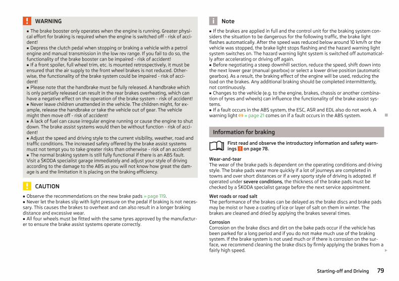
WARNING
■ The brake booster only operates when the engine is running. Greater physi-cal effort for braking is required when the engine is switched off - risk of acci-dent!■ Depress the clutch pedal when stopping or braking a vehicle with a petrolengine and manual transmission in the low rev range. If you fail to do so, thefunctionality of the brake booster can be impaired - risk of accident!■ If a front spoiler, full wheel trim, etc. is mounted retrospectively, it must beensured that the air supply to the front wheel brakes is not reduced. Other-wise, the functionality of the brake system could be impaired - risk of acci-dent!■ Please note that the handbrake must be fully released. A handbrake whichis only partially released can result in the rear brakes overheating, which canhave a negative effect on the operation of the brake system - risk of accident!■ Never leave children unattended in the vehicle. The children might, for ex-ample, release the handbrake or take the vehicle out of gear. The vehiclemight then move off - risk of accident!■ A lack of fuel can cause irregular engine running or cause the engine to shutdown. The brake assist systems would then be without function - risk of acci-dent!■ Adjust the speed and driving style to the current visibility, weather, road andtraffic conditions. The increased safety offered by the brake assist systemsmust not tempt you to take greater risks than otherwise - risk of an accident!■ The normal braking system is still fully functional if there is an ABS fault.Visit a ŠKODA specialist garage immediately and adjust your style of drivingaccording to the damage to the ABS as you will not know how great the dam-age is and the limitation it is placing on the braking efficiency.
CAUTION
■ Observe the recommendations on the new brake pads » page 119.■ Never let the brakes slip with light pressure on the pedal if braking is not neces-sary. This causes the brakes to overheat and can also result in a longer brakingdistance and excessive wear.■ All four wheels must be fitted with the same tyres approved by the manufactur-er to ensure the brake assist systems operate correctly.
Note
■ If the brakes are applied in full and the control unit for the braking system con-siders the situation to be dangerous for the following traffic, the brake lightflashes automatically. After the speed was reduced below around 10 km/h or thevehicle was stopped, the brake light stops flashing and the hazard warning lightsystem switches on. The hazard warning light system is switched off automatical-ly after accelerating or driving off again.■ Before negotiating a steep downhill section, reduce the speed, shift down intothe next lower gear (manual gearbox) or select a lower drive position (automaticgearbox). As a result, the braking effect of the engine will be used, reducing theload on the brakes. Any additional braking should be completed intermittently,not continuously.■ Changes to the vehicle (e.g. to the engine, brakes, chassis or another combina-tion of tyres and wheels) can influence the functionality of the brake assist sys-tems.■ If a fault occurs in the ABS system, the ESC, ASR and EDL also do not work. Awarning light » page 21 comes on if a fault occurs in the ABS system. Ð
Information for braking
First read and observe the introductory information and safety warn-ings on page 78.
Wear-and-tearThe wear of the brake pads is dependent on the operating conditions and drivingstyle. The brake pads wear more quickly if a lot of journeys are completed intowns and over short distances or if a very sporty style of driving is adopted. Ifoperated under severe conditions, the thickness of the brake pads must bechecked by a ŠKODA specialist garage before the next service appointment.
Wet roads or road saltThe performance of the brakes can be delayed as the brake discs and brake padsmay be moist or have a coating of ice or layer of salt on them in winter. Thebrakes are cleaned and dried by applying the brakes several times.
CorrosionCorrosion on the brake discs and dirt on the bake pads occur if the vehicle hasbeen parked for a long period and if you do not make much use of the brakingsystem. If the brake system is not used much or if there is corrosion on the sur-face, we recommend cleaning the brake discs by firmly applying the brakes from afairly high speed. £
ä
79Starting-off and Driving

Faults in the brake surfaceIf it is found that the braking distance has suddenly become longer and that thebrake pedal can be depressed further, the brake system may be faulty. Visit aŠKODA specialist garage immediately and adjust your style of driving appropriate-ly as you will not know how great the damage is.
Low brake fluid levelAn insufficient level of brake fluid may result in problems in the brake system. Thelevel of the brake fluid is monitored electronically » page 18, Brake system .
Brake boosterThe brake booster increases the pressure generated with the brake pedal. Thebrake booster only operates when the engine is running. Ð
Handbrake
Fig. 80 Centre console: Handbrake
First read and observe the introductory information and safety warn-ings on page 78.
Apply› Pull the handbrake lever firmly upwards.
Loosening› Pull the handbrake lever up slightly and at the same time push in the locking
button » Fig. 80.› Move the lever right down while pressing the lock button.
The handbrake warning light lights up when the handbrake is applied, providedthe ignition is on. Ð
ä
Stabilisation control (ESC)
First read and observe the introductory information and safety warn-ings on page 78.
The ESC is automatically activated after starting the engine. The ESC helps tomaintain control of the vehicle in situations where it is being operated at its dy-namic limits, such as a sudden change to the direction of travel. The risk of skid-ding is reduced and your car thus offers greater driving stability depending on theconditions of the road surface.
The direction which the driver wishes to take is determined based on the steeringangle and the speed of the vehicle and is constantly compared with the actualbehaviour of the vehicle. In the event of deviations, such as if the car starts toskid, the ESC automatically brakes the appropriate wheel.
During an intervention of the system, the warning light flashes in the instru-ment cluster.
In the event of an ESC fault, the ESC warning light illuminates in the instrumentcluster » page 20.
The following systems are integrated into the electronic stabilisation control(ESC):› Antilock brake system (ABS),› Traction control (TCS),› Electronic Differential Lock (EDL)› Brake assist,› Uphill start assist.
It is not possible to deactivate ESC. You can only use the button » Fig. 81 onpage 81 to switch off ASR. The TCS warning light lights up in the instrumentcluster when the TCS is switched off.
Hydraulic brake assistThe brake assist system is activated by the very quick operation of the brake ped-al (e.g. in the event of danger). It increases the braking effect and helps to short-en the braking distance. To achieve the shortest possible braking distance, thebrake pedal must be applied firmly and held in this position until the vehicle hascome to a complete standstill.
The ABS is activated faster and more effectively with the intervention of thebrake assist system.
The brake assist function is automatically switched off when the brake pedal isreleased. £
ä
80 Using the system

Uphill start assistThe uphill start assist makes it easier to start off on steep hills. The system holdsthe brake pressure produced by the activation of the brake pedal for approx.2 seconds after the brake pedal is released. The driver can therefore move hisfoot from the brake pedal to the accelerator pedal and start off on the slope,without having to actuate the handbrake. The brake pressure drops gradually themore you operate the accelerator pedal. If the vehicle does not start off within 2seconds, it starts to roll back.
The uphill start assist is active as of a 5 % slope, if the driver door is closed. It isalways active on slopes when in forward or reverse start off. When driving down-hill, it is inactive. Ð
Antilock brake system (ABS)
First read and observe the introductory information and safety warn-ings on page 78.
ABS prevents the wheels locking when braking. Thus helping the driver to main-tain control of the vehicle.
The intervention of the ABS is noticeable from the pulsating movements of thebrake pedal which is accompanied by noises.
Do not reduce the pressure on the brake pedal during the intervention of theABS. The ABS deactivates if the brake pedal is released. Never interrupt the appli-cation of the brakes during the intervention of the ABS! Ð
Traction control system (TCS)
Fig. 81 TCS button
ä
First read and observe the introductory information and safety warn-ings on page 78.
The TCS is automatically activated after starting the engine. If the wheels areslipping, the TCS adapts the engine speed to the conditions of the road surface.The TCS makes it much easier to start off, accelerate and climb steep hills even ifthe conditions of the road surface are unfavourable.
The TCS should normally always be switched on. It may be advisable to switch offthe system in certain exceptional circumstances, such as:› when driving with snow chains;› when driving in deep snow or on a very loose surface;› when it is necessary to “rock a vehicle free” when it has got stuck.
Ensure the TCS is switched on again afterwards.
During an intervention of the system, the TCS warning light flashes in the in-strument cluster.
The TCS warning light » page 23 lights up in the instrument cluster when thereis a fault on the TCS.
You can switch the TCS off and on again as you wish by pressing the button » Fig. 81. The TCS warning light lights up in the instrument cluster when theTCS is switched off. Ð
Electronic differential lock (EDL)
First read and observe the introductory information and safety warn-ings on page 78.
If one of the wheels starts to spin, the EDL system brakes the spinning wheel andtransfers the driving force to the other wheels. This ensures the stability of thevehicle and a quick journey.
The EDL switches off automatically if unusually severe stresses exist in order toavoid excessive heat generation in the disc brake on the wheel which is beingbraked. The vehicle can continue to be driven and has the same characteristics asa vehicle not fitted with EDL. The EDL switches on again automatically as soon asthe brake has cooled down. Ð
ä
ä
81Starting-off and Driving

Shifting (manual gearbox)
Fig. 82 Shift pattern of the 5-speedmanual gearbox
Always depress the clutch pedal fully when changing gear, to prevent excessivewear of the clutch.
The gearshift indicator must be observed when changing gear » page 11, Recom-mended gear.
Only engage reverse gear when the vehicle is stationary. Depress the clutch pedaland hold it fully depressed. Wait a moment before reverse gear is engaged toavoid any shift noises.
The reversing lights will come on once reverse gear is engaged, provided the igni-tion is on.
WARNING
Never engage reverse gear when driving - risk of accident!
Note
If not in the process of changing gear, do not leave your hand on the gearshiftlever while driving. The pressure from the hand can cause the gearshift mecha-nism to wear excessively. Ð
pedals
The operation of the pedals must not be hindered under any circumstances!
In the driver's footwell, only a footmat, which is attached to the two correspond-ing attachment points, may be used.
Only use footmats from the range of ŠKODA Original Accessories, which are fittedto two attachment points.
WARNING
No objects are allowed in the driver's footwell – risk of obstruction or limita-tion in operating the pedal! Ð
Parking aid
Fig. 83 Parking aid: Range of sensors
The parking aid determines the distance between the rear bumper and an obsta-cle with the aid of ultrasound sensors. The sensors are integrated in the rearbumper.
Range of sensorsThe clearance warning begins at a distance of about 160 cm from the obstacle(area A » Fig. 83). The interval between the warning signals becomes shorter asthe clearance is reduced.
A continuous tone sounds from a distance of approx. 30 cm (area B ) - dangerarea. You should not reverse any further after this signal sounds!
On vehicles with a factory-fitted radio or navigation system, the distance to theobstacle is simultaneously graphically illustrated on the display, refer to the oper-ating instructions for the radio or navigation system.
On vehicles with a factory-fitted towing device, the border of the danger areastarts (continuous tone) 5 cm further away from the vehicle. The length of the ve-hicle can be increased with an installed detachable towing device.
On vehicles with a factory-fitted towing device, the rear sensors are deactivatedwhen towing a trailer. £
82 Using the system

Activating/deactivating the parking aidThe parking aid is activated automatically when reverse gear is engaged and theignition is turned on. This is confirmed by a brief audible signal.
The parking aid is deactivated by removing the reverse gear.
WARNING
■ The parking aid is not a substitute for the driver paying proper attention andit is always the driver's responsibility to take care when reversing the vehicleor carrying out similar manoeuvres. Pay particular attention to small childrenand animals as they are not recognised by the parking aid sensors.■ Before reversing or parking, check that there is no small obstacle, such as arock, thin post, trailer drawbar etc., in front of or behind the vehicle. Such ob-stacles may not be recognised by the parking aid sensors.■ Under certain circumstances, surfaces of certain objects and types of cloth-ing cannot reflect the signals from the parking aid. Thus, these objects or peo-ple who wear such clothing are not recognised by the parking aid sensors.■ External sound sources can have a detrimental effect on the parking aid.Under unfavourable conditions, objects or people may not be recognised.
Note
■ If a warning signal sounds for about 3 seconds after activating the system andthere is no obstacle close to your car, this indicates a system fault. Have the faultrectified by a ŠKODA specialist garage.■ The sensors must be kept clean (free of ice, etc.) to enable the parking aid tooperate properly.■ If the parking aid is activated and the selector lever of the automatic gearbox isin the position P, the warning signal is interrupted (the vehicle cannot move). Ð
Cruise control system (CCS)
ä Introduction
This chapter contains information on the following subjects:
Storing a speed 84Changing a stored speed 84Switching off the cruise control system temporarily 84Switching off the cruise control system completely 84
The cruise control system (CCS) maintains a constant speed, more than 30 km/h,once it has been set, without you having to depress the accelerator pedal. This isonly possible within the range which is permitted by the power output and brak-ing power of the engine.
The warning light illuminates in the instrument cluster when the cruise controlsystem is activated.
WARNING
■ For safety reasons, the cruise control system must not be used in densetraffic or on unfavourable road surfaces (such as icy roads, slippery roads,loose gravel) - risk of accident!■ The saved speed may only be resumed if it is not too high for the currenttraffic conditions.■ Always switch off the cruise control system after use to prevent uninten-tional use of the system.
CAUTION
■ Always depress the clutch pedal if switching to the neutral position (vehiclewith a manual gearbox) when the cruise control system is switched on! Otherwisethe engine can rev up unintentionally.■ The cruise control system is not able to maintain a constant speed when drivingin areas with steeper gradients. The weight of the vehicle increases the speed atwhich it travels. Therefore, shift to a lower gear in good time or slow the vehicledown by applying the foot brake.
Note
It is not possible on vehicles fitted with an automatic gearbox to switch on thecruise control system if the selector lever is in the position P, N or R. Ð
83Starting-off and Driving

Storing a speed
Fig. 84 Turn signal and main beam lever:Rocker switch and switch of thecruise control system
First read and observe the introductory information and safety warn-ings on page 83.
Storing a speed› Turn the switch A » Fig. 84 into the ON position.› After the desired speed has been reached, press the rocker button B into the
SET position.
After you have released the rocker button B out of the position SET, the speedyou have just stored is maintained at a constant speed without having to depressthe accelerator. Ð
Changing a stored speed
First read and observe the introductory information and safety warn-ings on page 83.
Increasing the speed with the accelerator› Depress the accelerator to increase the speed.› Release the accelerator to reduce the speed back down to the preset speed.
However, if the saved speed is exceeded by more than 10 km/h for a period ofmore than 5 minutes by depressing the accelerator, the stored speed is deletedfrom the memory. The speed must then be saved again.
Increasing the speed with the rocker button B› Press the rocker button B » Fig. 84 on page 84 » page 84 into the RES posi-
tion.
ä
ä
› The speed will increase continuously, if the rocker button is pressed and held inthe RES position. Release the rocker button once the desired speed is reached.The set speed is then stored in the memory.
Decreasing the speed› The stored speed can be reduced by pressing the rocker button B » Fig. 84 on
page 84 into the position SET.› The speed will decrease continuously, if the rocker button is pressed and held
in the SET position. Release the rocker button once the desired speed isreached. The set speed is then stored in the memory.
› If the rocker button is released at a speed of less than 30 km/h, the speed isnot stored and the memory is erased. The speed must then be stored again bypressing the rocker button B in the position SET after increasing the speed ofthe vehicle to more than 30 km/h.
The speed can also be reduced by depressing the brake pedal, which temporarilydeactivates the system. Ð
Switching off the cruise control system temporarily
First read and observe the introductory information and safety warn-ings on page 83.
The cruise control system is temporarily switched off by pressing the switchA » Fig. 84 on page 84 into the spring-tensioned position CANCEL or by depress-
ing the brake or clutch pedal.
The set speed remains stored in the memory.
Briefly press the rocker button B into the position RES to resume the storedspeed after the clutch or brake pedal is released. Ð
Switching off the cruise control system completely
First read and observe the introductory information and safety warn-ings on page 83.
› Turn the switch A » Fig. 84 on page 84 into the OFF position. Ð
ä
ä
84 Using the system

START/STOP
Fig. 85 Centre console: Button for theSTART-STOP system
The START-STOP system helps you to save fuel while at the same time reducingharmful exhaust emissions and CO2 emissions.
The function is automatically activated each time the ignition is switched on.
In the start-stop mode, the engine automatically switches to the vehicle's idlephase, e.g. when stopped at traffic lights.
Information regarding the current state of the START-STOP system is indicated inthe display of the instrument cluster.
Automatic engine shut down (stop phase)› Stop the vehicle (where necessary, apply the handbrake).› Take the vehicle out of gear.› Release the clutch pedal.
Automatic renewed engine restart (start phase).› Depress the clutch pedal.
Switching the START-STOP system on and offThe START/STOP system can be switched on/off by pressing the button » Fig. 85.
When start-stop mode is deactivated, the warning light in the button lights up.
If the vehicle is in the stop phase when manually switching off the system, theengine starts immediately.
The START-STOP system is very complex. Some of the procedures are hard tocheck without servicing. The general conditions for the proper functioning of theSTART-STOP system are listed in the following overview.
Conditions for the automatic engine shut down (stop phase)› The gearshift lever is in Neutral.› The clutch pedal is not depressed.› The driver has fastened the seat belt.› The driver's door is closed.› The bonnet is closed.› The vehicle is at a standstill.› The factory-fitted towing device is not electrically connected to a trailer.› The engine is at operating temperature.› The charge state of the vehicle battery is sufficient.› The stationary vehicle is not on a steep slope or a steep downhill section.› The engine speed is less than 1 200 rpm.› The temperature of the vehicle battery is not too low or too high.› There is sufficient pressure in the braking system.› The difference between the outdoor- and the set temperature in the interior is
not too great.› The vehicle speed since the last time the engine was switched off was greater
than 3 km/h.› No cleaning of the diesel particle filter takes place » page 22.› The front wheels are not turned excessively (the steering angle is less than 3/4
of a steering wheel revolution).
Conditions for an automatic restart (start phase)› The clutch is depressed.› The max./min. temperature is set.› The defrost function for the windscreen is switched on.› A high blower stage has been selected.› The START STOP button is pressed.
Conditions for an automatic restart without driver intervention› The vehicle moves at a speed of more than 3 km/h.› The difference between the outdoor- and the set temperature in the interior is
too great.› The charge state of the vehicle battery is not sufficient.› There is insufficient pressure in the braking system.
If the driver's seat belt is removed for more than 30 seconds or the driver's door isopened during stop mode, the engine must be started manually with the key. Thefollowing messages in the instrument cluster display must be observed. £
85Starting-off and Driving

Messages in the instrument cluster display (valid for vehicles withoutInformation display)ERROR START STOP
Error in the START-STOP system
START STOP NOT POSSIBLE Automatic engine shut down is notpossible.
START STOP ACTIVE Automatic engine shut down (stopphase)
SWITCH OFF IGNITIONSwitch off the ignition.
START MANUALLYStart the engine manually.
WARNING
■ The brake servo unit and power steering only operate if the engine is run-ning.■ Never let the vehicle roll with the engine switched off.
CAUTION
Deactivate the START-STOP system before driving through water on thestreet » page 124.
Note
■ Changes to the outdoor temperature can have an effect on the internal temper-ature of the vehicle battery even after several hours. If the vehicle remains out-doors for a long time in minus temperatures or in direct sunlight, it can take sev-eral hours until the internal temperature of the vehicle battery reaches a suitabletemperature for proper operation of the START STOP system.■ If the Climatronic is running in automatic mode, under certain conditions, theengine may not switch off automatically. Ð
86 Using the system

Automatic gearbox
Automatic gearbox
ä Introduction
This chapter contains information on the following subjects:
Introductory information 87Starting-off and driving 88Selector lever positions 88Manual shifting of gears (Tiptronic) 89Selector lever lock 89Kickdown function 90Dynamic shift programme 90Emergency programme 90Selector lever-emergency unlocking 91
WARNING
■ Do not depress the accelerator if changing the position of the selector leverwhen the vehicle is stationary and the engine is running - risk of accident!■ Never move the selector lever into position R or P when driving - risk of anaccident!■ When the engine is running and the vehicle is stationary, it is necessary tohold the car with the brake pedal in all the positions of the selector lever (ex-cept P and N) since the power transmission is never completely interrupted,also not when the engine is idling - the vehicle creeps.■ The selector lever must be placed into position P and the handbrake firmlyapplied before the bonnet can be opened and work on the running engine canbe completed - risk of accident! The safety guidelines must always be ob-served » page 136, Engine compartment.
WARNING (Continued)
■ If stopping on a hill (downhill gradient), never try to maintain the vehicle sta-tionary with the gear engaged by means of the “accelerator pedal”, i.e. by let-ting the clutch slip. This can lead to overheating of the clutch. If there is a riskof overheating of the clutch due to overload, the clutch is opened automati-cally and the vehicle rolls backward - risk of accident!■ If you have to stop on a slope, depress and hold the brake pedal to preventthe vehicle from rolling back.■ On a smooth or slippery road surface using the kickdown function can causethe driven wheels to spin - risk of skidding!
CAUTION
■ The double clutch on the automatic gearbox DSG is equipped with an overloadprotection. If the uphill function is used when the vehicle is stationary or drivingslowly uphill, the thermal stress on the clutches is increased.■ If the clutch system overheats, the symbol is shown in the information dis-play along with the message Gearbox overheated. Stop! Owner's man.! appears.An audible signal sounds as a warning signal. Stop the vehicle, switch off the en-gine, and wait until the symbol disappears - risk of gearbox damage! You cancontinue your journey as soon as the symbol disappears. Ð
Introductory information
First read and observe the introductory information and safety warn-ings on page 87.
Shifting up and down through the gears is performed automatically. The gearboxcan also be switched to Tiptronic mode. This mode makes it possible for you toalso shift gears manually » page 89.
The engine can only be started when the selector lever is in position P or N . Ifthe selector lever is not in the P or N positions when locking the steering, switch-ing the ignition on or off or when leaving the engine on, the following messagewill appear in the Information display Move selector lever to position P/N! or, inthe instrument cluster display: P/N.
At temperatures below -10 °C the engine can only be started in the selector leverposition P 1). £
ä
1) Applies to DSG.
87Automatic gearbox
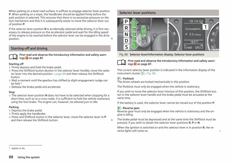
When parking on a level road surface, it suffices to engage selector lever positionP. When parking on a slope, the handbrake should be applied firmly before thepark position is selected. This ensures that there is no excessive pressure on thelock mechanism and that it is subsequently easier to move the selector lever outof position P.
If the selector lever position N is accidentally selected while driving, it is first nec-essary to release pressure on the accelerator pedal and wait for the idling speedof the engine to be reached before the selector lever can be engaged in the driveposition. Ð
Starting-off and driving
First read and observe the introductory information and safety warn-ings on page 87.
Starting off› Firmly depress and hold the brake pedal.› Press the Shiftlock button (button in the selector lever handle), move the selec-
tor lever into the desired position » page 88 and then release the Shiftlockbutton.
› Wait a moment until the gearbox has shifted (a slight engagement nudge canbe felt) 1).
› Release the brake pedal and accelerate.
Stop› The selector lever position N does not have to be selected when stopping for a
short time, such as at a cross roads. It is sufficient to hold the vehicle stationaryusing the foot brake. The engine can, however, be allowed just to idle.
Parking› Depress the brake pedal.› Firmly apply the handbrake.› Press and Shiftlock button in the selector lever, move the selector lever to P
and then release the Shiftlock button. Ð
ä
Selector lever positions
Fig. 86 Selector lever/information display: Selector lever positions
First read and observe the introductory information and safety warn-ings on page 87.
The current selector lever position is indicated in the information display of theinstrument cluster 1 » Fig. 86.
P - ParklockThe driven wheels are locked mechanically in this position.
The Parklock must only be engaged when the vehicle is stationary.
If you wish to move the selector lever into/out of this position, the Shiftlock but-ton in the selector lever handle and the brake pedal must be actuated at thesame time.
If the battery is used, the selector lever cannot be moved out of the position P.
R - Reverse gearReverse gear must only be engaged when the vehicle is stationary and the en-gine is idling.
The brake pedal must be depressed and at the same time the Shiftlock must bepressed, if you wish to obtain the selector lever positions R, P or N.
When the ignition is switched on and the selector lever is in position R, the re-verse lights will come on. £
ä
1) Applies to AG.
88 Using the system

N - NeutralThe transmission is in Neutral in this position.
The brake pedal must be depressed to move the selector lever out of the positionN (if the lever is in this position for longer than 2 seconds) into the position D or Rwhen the vehicle is travelling at less than 5 km/h or the vehicle is stationary andthe ignition is switched on.
D - Position for driving forward (normal programme)When the selector lever is in this position, the forward gears are automaticallyshifted up and down in line with the engine load, vehicle speed and dynamic shiftprogramme.
The brake pedal must be depressed to move the selector lever into position Dfrom Nwhen the vehicle is travelling at less than 5 km/h or is stationary.
Under certain circumstances (e.g. when driving in mountainous regions or whentowing a trailer) it may be beneficial to select the manual shift pro-gramme » page 89 for a short time in order to adapt the gearbox ratios manual-ly to the driving situations.
S - Position for driving forward (sports programme)Shifting up later into a higher gear makes it possible to fully exploit the power po-tential of the engine. The gearbox also then shifts down at higher engine speedsas in the position D.
The Shiftlock on the selector lever grip must be pressed when moving the selec-tor lever out of the position D into the position S. Ð
Manual shifting of gears (Tiptronic)
Fig. 87 Selector lever/information display: Selector lever positions
First read and observe the introductory information and safety warn-ings on page 87.
Tiptronic mode makes it possible to manually shift gears on the selector lever.
Switching to manual shifting› Push the selector lever to the right out of position D. The selector lever posi-
tion you have engaged is indicated in the information display of the instrumentcluster together with the engaged gear 1 » Fig. 87 on the right.
Shifting up gears› Press the selector lever forwards + » Fig. 87.
Shifting down gears› Press the selector lever backwards - » Fig. 87.
It is possible to switch to manual shifting when the car is stationary and whendriving.
When accelerating, the gearbox automatically shifts up into the higher gear justbefore the maximum permissible engine speed is reached.
If a lower gear is selected, the gearbox does not shift down until there is no riskof the engine overrevving.
If you operate the kickdown function, the gearbox shifts into a lower gear in linewith the vehicle speed and engine speed.
Note
The kickdown function is also available when manually shifting gears. Ð
Selector lever lock
First read and observe the introductory information and safety warn-ings on page 87.
Automatic selector lever lock With the ignition on, the selector lever is locked when it is in the positions P andN. The brake pedal must be depressed to move the selector lever out of this posi-tion. The indicator light » page 24 illuminates in the instrument cluster as a re-minder for the driver when the selector lever is in the positions P and N. £
ä
ä
89Automatic gearbox

The selector lever is not locked when quickly moving across the position N (e.g.from R to D). This, for example, helps to rock out a vehicle that is stuck. The selec-tor lever lock will click into place if the lever is in the N position for more than 2seconds without the brake pedal being pressed.
The selector lever lock is only active if the vehicle is stationary or moving at speedof less than 5 km/hour. The lock is switched off automatically into position Nwhen the car is travelling at a higher speed.
Shiftlock buttonThe Shiftlock button in the handle of selector lever prevents certain selector leverpositions being engaged inadvertently. The selector lever lock is cancelled whenthe Shiftlock button is pressed.
Ignition key withdrawal lockAfter the ignition is switched off, the ignition key can only be withdrawn if the se-lector lever is in the position P. If the ignition key is withdrawn, the selector leveris blocked in position P. Ð
Kickdown function
First read and observe the introductory information and safety warn-ings on page 87.
The kickdown function provides you with maximum acceleration power.
When the accelerator pedal is fully depressed, the kickdown function is activatedin the desired driving program. This function has precedence over the driving pro-gramme and serves for maximum acceleration of the vehicle when exploiting themaximum power potential of the engine without taking into account the currentselector lever position (D, S or Tiptronic). The gearbox shifts down to one or sev-eral gears in line with the driving state and the vehicle accelerates. The gearboxdoes not shift up into the highest gear until the engine has reached its maximumrevolutions for this gear range. Ð
Dynamic shift programme
First read and observe the introductory information and safety warn-ings on page 87.
The automatic gearbox of your vehicle is controlled electronically. Shifting up anddown through the gears is performed automatically on the basis of pre-defineddriving programmes.
ä
ä
Adopting a moderate style of driving will cause the gearbox to select the mosteconomical driving programme. Shifting up into a higher gear as soon as possibleand shifting down as late as possible will have a favourable effect on your fuelconsumption.
When adopting a sporty style of driving with rapid movements of the acceleratorpedal combined with sharp acceleration, frequent changes in speed and exploit-ing the top speed of the car, the gearbox will adjust to this style of driving oncethe accelerator pedal (kickdown function) is depressed and will shift down earlier,frequently by several gears in comparison to a moderate style of driving.
Selecting the most appropriate driving programme for the particular style of driv-ing is a continuous process. Irrespective of this it is, however, possible to switchor shift down into a dynamic shift programme by depressing the accelerator rap-idly. The gearbox shifts down into a lower gear in accordance with the speed,therefore enabling rapid acceleration (e.g. when overtaking) without the accelera-tor pedal having to be depressed into the kickdown range. The original pro-gramme will be reactivated to match your particular style of driving once thegearbox has shifted up again.
When driving in hilly regions, the gears are selected to match uphill and downhillsections. This avoids the gearbox frequently shifting up and down when negoti-ating an uphill stretch. When driving downhill, it is possible to shift down into theTiptronic position, in order to exploit the engine brake torque. Ð
Emergency programme
First read and observe the introductory information and safety warn-ings on page 87.
An emergency programme exists in the event of a fault in the system.
The gearbox operates in a corresponding emergency programme if there arefunctional faults in the gearbox electronics. All of the display elements illuminateor go out.
A functional fault can have the following effect:› The gearbox only shifts into certain gears;› The reverse gear R cannot be used,› The manual shift programme is switched off in emergency mode. £
ä
90 Using the system

Note
If the gearbox has switched to emergency mode, drive to a ŠKODA specialist ga-rage to have the fault rectified. Ð
Selector lever-emergency unlocking
Fig. 88 Selector lever-emergency un-locking
First read and observe the introductory information and safety warn-ings on page 87.
In case of interruption of the power supply (e.g. flat vehicle battery, defectivefuse) or defect of the selector lever lock, the selector lever can no longer be shif-ted from the position P in the normal way and the vehicle can no longer bemoved. The selector lever must be unlocked in case of emergency.› Firmly apply the handbrake.› Carefully pull up the front left and right cover.› Pull up rear cover.› Use a finger to press the yellow plastic part in the direction of the ar-
row » Fig. 88.› Simultaneously press the Shiftlock button in the handle of the selector lever
and shift the lever into the position N (if the selector lever is shifted back intothe position P, it is blocked again). Ð
ä
91Automatic gearbox

Communication
Mobile phones and two-way radio systems
ŠKODA permits the operation of mobile phones and two-way radio systems witha professionally installed external aerial and a maximum transmission power ofup to 10 watts.
Please refer to a ŠKODA Service Partner for information about the possibilities ofinstalling and operating mobile phones and two-way radio systems that have atransmission power of more than 10 W.
Operating mobile phones or two-way radio systems may interfere with the func-tionality of the electronic systems in your vehicle.
The reasons for this are as follows:› no external aerial;› external aerial incorrectly installed;› transmission power greater than 10 watts.
WARNING
■ Concentrate fully at all times on your driving! As the driver you are fully re-sponsible for road safety. Use the telephone system only to such an extentthat you are in full control of your vehicle at any time.■ The national regulations for using a mobile phone in a vehicle must be ob-served.■ If a mobile phone or a two-way radio system is operated in a vehicle withoutan external aerial or an external aerial which has been installed incorrectly,this can increase the strength of the electromagnetic field inside the vehicle.■ Two-way radio systems, mobile phones or mounts must not be installed onairbag covers or within the immediate deployment range of the airbags.■ Never leave a mobile phone on a seat, on the dash panel or in another area,from which it can be thrown during a sudden braking manoeuvre, an accidentor a collision - risk of injury.■ In the event of air transport, the Bluetooth® function for the hands-free sys-tem must be switched off by a specialist garage.
Note
■ We recommend that the installation of mobile phones and two-way radio sys-tems in a vehicle be carried out by a ŠKODA Service Partner.■ Not all mobile phones that enable Bluetooth® communication are compatiblewith the universal telephone preinstallation GSM II. You can ask an authorisedŠKODA Service Partner whether your telephone is compatible with the universaltelephone preinstallation GSM II.■ The range of the Bluetooth® connection to the hands-free system is restrictedto the vehicle interior. The range is dependent on local factors, e.g. obstacles be-tween the devices and mutual interferences with other devices. If your mobilephone is in a jacket pocket, for example, this can lead to difficulties when estab-lishing a connection with the hands-free-system or transferring data. Ð
Universal telephone preinstallation GSM II
Introductory information
The universal telephone preinstallation GSM II (hands-free system) includes aconvenience mode for the mobile phone via voice control, the multifunctionsteering wheel, the adapter, radio or the navigation system.
The universal telephone preinstallation GSM II comprises the following functions.› Phone Phonebook » page 93.› Convenience operation of the telephone via the multifunction steering
wheel » page 93.› Managing telephone calls via the adapter » page 94.› Operation of the telephone via the information display » page 95.› Voice control of the telephone » page 96.› Music playback from the telephone or other multimedia units » page 97.
All communication between a mobile phone and your vehicle's hands-free systemis established with the help of Bluetooth® technology. The adapter serves onlyfor charging the telephone and for transmitting the signal to the vehicle's exter-nal aerial.
Note
The following guidelines must be observed » page 92, Mobile phones and two-way radio systems. Ð
92 Using the system

Phone Phonebook
A phone phonebook is part of the hands-free system. This phone phonebook canbe used depending on the type of mobile phone.
After the first connection of the telephone, the system begins to load the phonebook from the phone and the SIM card into the memory of the control unit.
Each time the telephone has established a new connection with the hands-freesystem, an update of the relevant phone book is performed. The updating cantake a few minutes. During this time the phone book, which was stored after thelast update was completed, is available. Newly stored telephone numbers are on-ly shown after the updating has ended.
The update is interrupted if a telephone event (e.g. incoming or outgoing call,voice control dialogue) occurs during the updating procedure. After the telephoneevent has ended, the updating starts anew.
The internal phonebook provides 2 500 free memory locations. Each contact cancontain up to 4 numbers.
If the number of contacts loaded exceeds 2 500, the phone book is not complete. Ð
Operating the phone on the multifunction steering wheel
Fig. 89 Multifunction steering wheel:Mobile phone operation
The driver can set the basic functions of the telephone by simply operating thebuttons located on the steering wheel so that he can concentrate on the trafficsituation without being distracted as little as possible by operating the tele-phone » Fig. 89.
This applies only if your vehicle has been equipped with the universal telephonepreinstallation (hands-free system) at the factory.
If the side lights are switched on, the buttons and the symbols and on themultifunction steering wheel are illuminated.
Button Action Operation
1 Press briefly Accept call, terminate call, entry in the main menu of the telephone, list of selected numbers
1Press button for a long period
of timeReject call, last dialled numbera), switch on/off voice controlb)
2 Press briefly Switch on/off voice control
2 Turn upwards Increase volume
2 Turn downwards Decrease volume
a) Valid for vehicles with the Amundsen+ navigation system.b) Valid for vehicles without the Amundsen+ navigation system. Ð
93Communication

Inserting the mobile phone and adapter
Fig. 90 Universal telephone preinstalla-tion
Only one telephone mount is factory-fitted. An adapter for the mobile phone canbe purchased from ŠKODA Original Accessories.
Install› First of all push the adapter A in the direction of the arrow » Fig. 90 up to the
stop into the mount. Then press the adapter slightly downwards, until it lockssecurely into position.
› Insert the mobile phone into the adapter A (as specified in the instructionsfrom the manufacturer of the adapter).
Removing› Simultaneously press the locks on the mount » Fig. 90 and remove the adapter
with the mobile phone.
CAUTION
Taking the mobile phone out of the adapter during the call can lead to interrup-tion of the connection. When removing the mobile phone, the connection to thefactory-fitted antenna is interrupted, which reduces the quality of the transmit-ting and receiving signal. The charging of the mobile phone battery is also inter-rupted. Ð
Managing telephone calls with the help of the adapter
Fig. 91 Principle sketch: Adapter with one button/adapter with two buttons
Function overview of the » Fig. 91 (PTT - “push to talk”) button on the adapter:
› Switch on/off voice control;› Accept/end a call.
On some adapters include the button SOS A » Fig. 91 in addition to the button .After pressing this button for 2 seconds, the number 112 (Emergency call) is dial-led. Ð
Connecting the mobile phone to the hands-free system
To connect a mobile phone with the hands-free system, the two devices must bepaired. Detailed information on this is provided in the operating instructions foryour mobile phone.
The following steps must be carried out for the connection.› Activate Bluetooth® and the visibility of your mobile phone on your telephone.› Switch on the ignition.› Select the menu Phone - New user in the information display and wait until the
control unit has completed the search.› Select your mobile phone from the menu of the units found.› Confirm the PIN1). £
1) Depending on the Bluetooth® version on the mobile phone, an automatically generated 6-digit PIN iseither displayed or the PIN 1234 has to be entered manually.
94 Using the system

› If the hands-free system announces (as standard SKODA_BT) on the display ofthe mobile phone, enter the PIN1) within 30 seconds and wait, until the connec-tion is established2).
› After terminating the connection, confirm the creation of a new user profile inthe information display.
If there is no free space available to create a new user profile, delete an existinguser profile.
During the connecting procedure, no other mobile phone may be connected withthe hands-free system.
Up to four mobile phones can be paired with the hands-free system, whereby on-ly one mobile phone can communicate with the hands-free system.
The visibility of the hands-free system is automatically switched off 3 minutes af-ter the ignition is switched on and is also deactivated when the mobile phone hasconnected to the hands-free system.
Restoring the visibility of the hands-free system
If you have not managed to connect your mobile phone with the hands-free sys-tem within 3 minutes of switching on the ignition, the visibility of the hands-freesystem can be reestablished for 3 minutes in the following ways.› By turning the ignition off and on.› By turning voice control off and on.› Via the information display in the menu item Bluetooth - Visibility.
Creating a connection with an already paired mobile phoneAfter switching on the ignition, the connection is automatically established forthe already paired mobile phone2). Check on your mobile phone if the automaticconnection has been established.
Disconnecting the connection› By withdrawing the ignition key.› By disconnecting the hands-free system in the mobile phone.› By disconnecting the user in the information display in the menu Bluetooth -
User.
Solving connection problems
If the system announces No paired phone found, check the operating state of themobile phone.› Is the mobile phone switched on?› Is the PIN code entered?› Is Bluetooth® active?› Is the visibility of the mobile phone active?› Has the mobile phone already been paired with the hands-free system?
Note
■ If a suitable adapter is available for your mobile phone, only use your mobilephone in the adapter inserted in the telephone mount so that the radiation in thevehicle drops to a minimum.■ Placing the mobile phone in the adapter inserted in the telephone mount en-sures optimum sending and receiving power. Ð
Symbols in the information display
Symbol Importance
Charge status of the phone batterya)
Signal strengtha)
a phone is connected to the hands-free system.
The hands-free system is visible to other devices.
A multimedia unit is connected to the hands-free system.
a) This function is only supported by some mobile phones. Ð
Operate the telephone via the information display
The following menu points can be selected in the menu Phone.■ Phone book■ Dial number £
1) Depending on the Bluetooth® version on the mobile phone, an automatically generated 6-digit PIN iseither displayed or the PIN 1234 has to be entered manually.
2) Some mobile phones have a menu, in which the authorisation for establishing a Bluetooth® connec-tion is completed by inputting a code. If the authorisation input is required, it must always be per-formed when re-establishing the Bluetooth connection.
95Communication

■ Call register■ Voice mailbox■ Bluetooth■ Settings■ Back
Phone bookIn the menu point Phone book is the list of the loaded contacts from the tele-phone memory and the SIM card of the mobile phone.
Dial numberAny telephone number can be entered in the menu point Dial number. The re-quired numbers must be selected one after the other using adjustment wheeland confirmed by pressing the adjustment wheel. You can select numbers 0 - 9,symbols , , #, and functions Cancel, Call, and Delete.
Call register
The following menu items can be selected in the menu item Call register.■ Missed calls■ Dialled numbers■ Received calls
Voice mailboxIn the menu Voice mailbox, it is possible to set the number of the voice mailbox1)
and then dial the number.
Bluetooth
The following menu items can be selected in the menu Bluetooth.■ User - the overview of the stored users■ New user - Search for new mobile phones that are in the reception range■ Visibility - Switching on the visibility of the telephone unit for other devices■ Media player■ Active device■ Paired devices■ Search
■ Phone name - the possibility to change the name of the telephone unit (pre-setSKODA UHV)
Settings
The following menu items can be selected in the menu Settings.■ Phone book■ Update■ List■ Surname■ First name
■ Ring tone
BackReturn in the Start menu of the telephone. Ð
Voice control
Dialogue
The period of time during which the system is ready to receive voice commandsand to carry them out is called a dialogue. The system gives audible feedback andguides you if necessary through the relevant functions.
Optimum understanding of the voice commands depends on several factors.› Speak with a normal tone of voice without intonation and excessive pauses.› Avoid a bad pronunciation.› Close the doors, windows and sliding roof, to reduce or stop disturbing exterior
noise.› It is recommended to speak louder at higher speeds, so that the tone of your
voice is louder than the increased surrounding noise.› During the dialogue, limit additional noise in the vehicle, e.g. passengers talking
at the same time.› Do not speak, if the system makes an announcement.
The microphone for voice control is inserted in the moulded headliner and direc-ted to the driver and front passenger. Therefore the driver and the front passen-ger can operate the equipment. £
1) On vehicles fitted with the Amundsen+ navigation system, this function can be accessed via the navi-gation system menu; refer to the operating instructions for the Amundsen+ navigation system.
96 Using the system

Entering a phone numberThe telephone number can be entered as a continuous series of individually spo-ken digits (the whole number at once) or in the form of digital blocks (separatedby short pauses). After each order of digits (separation through brief voice pause)all of the digits detected up to now are repeated by the system.
The digits 0 - 9, symbols +, , # are permitted. The system detects no continuousdigit combinations such as twenty-three, but only individually spoken digits (two,three).
Switching on voice control› by briefly pressing the button on the adapter» Fig. 91 on page 94,› by briefly pressing the button 1 on the multi-function steering
wheel » page 93, Operating the phone on the multifunction steering wheel.
Switching off voice control
If the system is currently playing a message, the message that is currently beingplayed will have to be stopped:› by briefly pressing the button on the adapter;› by briefly pressing the button 1 on the multifunction steering wheel.
If the system expects a voice command, you can end the dialogue yourself:› with the CANCEL voice command;› by pressing the button on the adapter;› by briefly pressing the button 1 on the multifunction steering wheel.
Note
■ The dialogue of an incoming call is immediately interrupted.■ The voice control is only possible in vehicles fitted with a multifunction steeringwheel with telephone control or a phone mount and adapter. Ð
Voice commands
Basic voice commandsVoice command Action
HELPAfter this command the system repeats all possiblecommands.
CALL XYZThis command calls up the contact from the phonebook.
Voice command Action
PHONE BOOKAfter this command, for example, the phone bookcan be repeated back to you, a voice entry for thecontact can be updated or deleted, etc.
CALL HISTORY Lists of dialled numbers, missed calls, etc.
DIAL NUMBERAfter this command, a telephone number can be en-tered to establish a connection with the requestedparty.
REDIALAfter this command the system calls the last diallednumber.
MUSICPlay music from the mobile phone or another paireddevice.
FURTHER OPTIONSAfter this command the system offers additionalcontext-dependent commands.
SETTINGS Selection for setting Bluetooth®, dialogue etc.
CANCEL The dialogue is ended.
If a voice command is not detected, the system answers with “Sorry?” and a newentry can be completed. After the 2nd error the system repeats the aid. After the3rd error the answer “Cancelled” is given and the dialogue is ended.
Store voice recording of a contactIf automatic name recognition does not work reliably for some contacts, you canchoose to save your own voice entry for the contact in the menu Phone book -Voice Tag - Record.
Your own voice entry can also be saved using the voice control in the menu FUR-THER OPTIONS. Ð
Multimedia
Music playback via Bluetooth®
The universal telephone preinstallation GSM II makes it possible to play back mu-sic via Bluetooth® from the devices such as MP3 player, mobile phone or note-book.
To ensure the music can be played back via Bluetooth®, it is necessary to connectthe terminal device with the hands-free system in the menu Phone - Bluetooth -Media player. £
97Communication

The music playback process is performed on the connected device.
The universal telephone preinstallation GSM II ensures that the music played backvia the hands-free system can be controlled with the remote control » page 97,Voice commands.
Note
The device being connected must support the Bluetooth® A2DP profile; refer tothe operating instructions for the relevant device being connected. Ð
Operating the radio and navigation system on the multifunction steering wheel
Fig. 92 Multifunction steering wheel:control buttons
The multifunction steering wheel comprises buttons for setting the basic func-tions for the factory-fitted radio and navigation system » Fig. 92.
The radio and navigation system can of course still be operated on the devices. Adescription is included in the relevant operating instructions.
If the side lights are switched on, the buttons on the multifunction steeringwheel are illuminated.
The buttons apply for the respective operating mode of the current radio or navi-gation system.
The following functions can be completed by pressing or turning the buttons.
Button Action Radio, traffic information CD/MP3/Navigation
1 Press briefly Switch off/on tone
1Press button for along period of time
Switch the unit on/off
1 Turn upwards Increase volume
1 Turn downwards Decrease volume
2 Press brieflySwitch to the next stored radio station
Interruption of the traffic reportChanging to the next title
2Press button for along period of time
Search forwards Fast forward
3 Press brieflySwitch to the previous stored radio station
Interruption of the traffic reportChanging to the previous title
3Press button for along period of time
Search backwards Fast rewind £
98 Using the system
Note
■ The functions of button 1 are different for vehicles fitted with a universal tele-phone preinstallation GSM II » page 93.■ The loudspeakers in the vehicle are adjusted to the power output of the radioand navigation system of 4x20°W. Ð
AUX-IN and MDI inputs
The AUX-IN input is located below the front armrest and is marked with .
The MDI input is located beneath the storage compartment on the front passen-ger side.
The AUX-IN and MDI inputs are used to connect external audio sources (e.g. iPodor mp3 player) and to play back music from these devices via the factory-fitted ra-dio or navigation system.
For a description of use, refer to the operating instructions for the relevant radioor navigation system. Ð
99Communication

Safety
Passive Safety
General information
ä Introduction
This chapter contains information on the following subjects:
Safety equipment 100Before setting off 100What influences the driving safety? 101
In this section you will find important information, tips and notes on the subjectof passive safety in your vehicle. We have combined everything here which youshould be familiar with, for example, regarding seat belts, airbags, child seats andsafety of children. It is therefore important, in particular, to comply with the notesand warnings in this section for your own interest and in the interest of thosetravelling with you.
WARNING
■ This chapter contains important information on how to use the vehicle forthe driver and his occupants. You will find further information on safety, whichconcerns you and those travelling with you, in the following chapters of thisOwner's Manual.■ The complete on-board literature should always be in the vehicle. This ap-plies in particular, if you rent out or sell the vehicle. Ð
Safety equipment
First read and observe the introductory information and safety warn-ings on page 100.
The following list contains part of the safety equipment in your vehicle:
› three-point seat belts for all the seats;› belt force limiters for the front seats;
ä
› belt tensioners for front seats;› seat belt height adjusters for front seats;› Front airbag for the driver and the front seat passenger;› side airbags;› head airbags;› anchoring points for child seat using the ISOFIX system;› anchoring points for child seat using the TOP TETHER system;› head restraints adjustable for height;› adjustable steering column.
The specified safety equipment works together, in order to optimally protect youand those travelling with you in accident situations. The safety equipment doesnot protect you or the people travelling with you, if you or your occupants adoptan incorrect seated position or the equipment is not correctly adjusted or used. Ð
Before setting off
First read and observe the introductory information and safety warn-ings on page 100.
For your own safety and the safety of the people travelling with you, please payattention to the following points before setting off.
› Ensure that the lighting and the turn signal system are functioning properly.› Check the tyre inflation pressure.› Ensure that all of the windows offer good visibility to the outside.› Secure all items of luggage » page 51, Boot.› Ensure that no objects can obstruct the pedals.› Adjust the mirrors, the front seat and head restraint to your body size.› Advise your passengers to adjust the head restraints to their body size.› Protect children in suitable child seats with correctly fastened seat
belts » page 115, Transporting children safely.› Adopt the correct seated position » page 101. Tell your passengers to assume
the correct seated position.› Correctly fasten the seat belt. Also inform passengers to fasten the seat belt
correctly » page 104, Seat belts. Ð
ä
100 Safety

What influences the driving safety?
First read and observe the introductory information and safety warn-ings on page 100.
The driver is fully responsible for himself and his occupants. If your driving safetyis effected, you place yourself and the oncoming traffic at risk.
The following guidelines must therefore be observed.› Do not get distracted from concentrating on the traffic situation, e.g. by your
passengers or mobile phone calls.› Never drive when your driving ability is impaired, e.g. through medication, alco-
hol, drugs.› Keep to the traffic regulations and the permissible speed limit.› Always adjust the driving speed to the road, traffic and weather conditions.› Take regular breaks on long journeys – at least every two hours. Ð
Correct seated position
ä Introduction
This chapter contains information on the following subjects:
Correct seated position for the driver 102Correct seated position for the front passenger 102Correct seated position for the occupants on the rear seats 102Examples of an incorrect seated position 102
WARNING
■ The front seats and the head restraints must always be adjusted to matchthe body size of the seat occupant as well as the seat belts must always becorrectly fastened in order to provide an optimal protection for you and youroccupants.■ Always assume the correct seated position before setting off and do notchange this position while driving. Also advise your passengers to adopt thecorrect seated position and not to change this position while the car is mov-ing.
ä
WARNING (Continued)
■ If the occupant adopts an incorrect seated position, he is exposed to life-threatening injuries, in case he is hit by a deployed airbag.■ If the occupants on the rear seats are not sitting upright, the risk of injury isincreased due to incorrect routing of the seat belt.■ The driver must maintain a distance of at least 25 cm to the steering wheel.The front passenger must maintain a distance of at least 25 cm to the dashpanel. Not maintaining this minimum distance will mean that the airbag sys-tem will not be able to properly protect you - hazard!■ When driving, hold the steering wheel with both hands firmly on the outeredge in the 9 o'clock and 3 o'clock position. Never hold the steering wheel inthe 12 o'clock position or in any other way (e.g. in the middle or inner edge ofthe steering wheel). In such cases, you could severely injure the arms, handsand head when the driver airbag is deployed.■ The seat backrests must not be angled too far back when driving otherwisethis will affect proper operation of the seat belts and of the airbag system -risk of injury!■ Ensure that there are no objects in the driver's footwell as they may getcaught behind the pedals when driving or applying the braking. You wouldthen no longer be able to operate the clutch, brake or accelerate.■ Always keep your feet in the footwell when the car is being driven - neverplace your feet on the instrument panel, out of the window or on the surfacesof the seats. You will be exposed to increased risk of injury if it becomes nec-essary to apply the brake or in the event of an accident. If an airbag is de-ployed, you may suffer fatal injuries when adopting an incorrect seated posi-tion! Ð
101Passive Safety

Correct seated position for the driver
Fig. 93 The correct distance of the driver to the steering wheel/The correcthead restraint adjustment
First read and observe the introductory information and safety warn-ings on page 101.
For your own safety and to reduce the risk of injury in the event of an accident,we recommend the following setting.
› Adjust the steering wheel so that the distance A » Fig. 93 between the steer-ing wheel and your chest is at least 25 cm.
› Adjust the driver’s seat in the forward/back direction so that the pedals can befully depressed with slightly bent legs.
› Adjust the seat backrest so that the highest point of the steering wheel can bereached with your arms at a slight angle.
› Adjust the head restraint so that the top edge B of the head restraint is at thesame level as the upper part of your head.
› Correctly fasten the seat belt » page 104, Seat belts.
Driver seat adjustment » page 47, Adjusting the front seats. Ð
Correct seated position for the front passenger
First read and observe the introductory information and safety warn-ings on page 101.
ä
ä
For the safety of the front passenger and to reduce the risk of injury in the eventof an accident, we recommend the following setting.
› Position the front passenger seat back as far as possible. The front passengermust maintain a distance of at least 25 cm to the dash panel so that the airbagoffers the greatest possible safety if it is deployed.
› Adjust the head restraint so that the top edge B » Fig. 93 onpage 102 » page 102 of the head restraint is at the same level as the upper partof your head.
› Correctly fasten the seat belt » page 104, Seat belts.
In exceptional cases the front passenger airbag can be deactivated » page 113,Deactivating airbags.
Front passenger adjustment » page 47, Adjusting the front seats. Ð
Correct seated position for the occupants on the rear seats
First read and observe the introductory information and safety warn-ings on page 101.
To reduce the risk of injury in the event of a sudden braking manoeuvre or an ac-cident, the occupants on the rear seats must observe the following.
› Adjust the head restraint so that the top edge B » Fig. 93 onpage 102 » page 102 of the head restraint is at the same level as the upper partof your head.
› Correctly fasten the seat belt » page 104.› Use a suitable child restraint system if transporting children in the vehi-
cle » page 115, Transporting children safely. Ð
Examples of an incorrect seated position
First read and observe the introductory information and safety warn-ings on page 101.
Seat belts offer their optimum protection only if the webbing of the seat belts isproperly routed. Incorrect seated positions considerably reduce the protectivefunctions of the seat belts and therefore increase the risk of injury due to an in-correct routing of the seat belt. The driver is fully responsible for himself and pas-sengers, especially children. Never allow a passenger to adopt an incorrect seatedposition when the car is moving. £
ä
ä
102 Safety

The following list contains examples of which seated positions can cause seriousinjuries or death. This list is not complete, however we would like you to familiar-ise yourself with this subject.
Therefore, while the car is moving never:› stand up in the vehicle;› stand up on the seats;› kneel on the seats;› tilt the seat backrest fully to the back;› lean against the dash panel;› lie on the rear seat bench;› only sit on the front area of the seat;› sit to the side;› lean out of the window;› put the feet out of the window;› put the feet on the dash panel;› put the feet on the seat upholstery;› transport somebody in the footwell;› have the seat belt not fastened when driving;› be in the boot. Ð
103Passive Safety

Seat belts
Seat belts
ä Introduction
Fig. 94 Driver wearing seat belt
This chapter contains information on the following subjects:
The physical principle of a frontal collision 105Fastening and unfastening seat belts 106Seat belt height adjuster on the front seats 107Seat belt for the rear middle seat 107Belt tensioners 107
Seat belts that are fastened correctly offer good protection in the event of an ac-cident. They reduce the risk of an injury and increase the chance of survival in theevent of a major accident.
Correctly fastened seat belts hold occupants of the car in the correct seated posi-tion » Fig. 94.
The seat belts reduce the kinetic energy (energy of motion) to a considerable ex-tent. They also prevent uncontrolled movements which, in turn, may well result insevere injuries.
The occupants of a vehicle who have fastened and correctly adjusted their seatbelt, profit to a major extent from the fact that the kinetic energy is optimally ab-sorbed by the belts. The structure of the front end of the vehicle and other pas-sive safety measures, such as the airbag system, also contribute to reducing thekinetic energy. The energy produced is thus absorbed and there is less risk of in-jury.
Particular safety aspects must be observed when transporting children in the ve-hicle » page 115, Transporting children safely.
WARNING
■ Fasten your seat belt before each journey - even when driving in town! Thisalso applies to the people seated at the rear - risk of injury!■ Expectant women must also always wear a seat belt. This is the only way ofensuring optimal protection for the unborn child » page 106, Fastening andunfastening seat belts.■ Adjust the height of the belt in such a way that the shoulder part of the beltis roughly positioned across the middle of your shoulder - on no accountacross your neck.■ Always ensure that the webbing of the seat belts is properly routed. Seatbelts which are not correctly adjusted can themselves cause injuries even inminor accidents.■ The maximum protection which seat belts can offer is only achieved if youare correctly seated » page 101, Correct seated position.■ The seat backrests of the front seats must not be tilted too far to the rearotherwise the seatbelts can lose their effectiveness.■ The belt webbing must not be jammed in-between at any point or twisted,or chafe against any sharp edges.■ A seat belt which is hanging too loose can result in injuries as your body ismoved forward by the kinetic energy produced in an accident and is then sud-denly held firm by the belt.■ The belt webbing must not run across solid or fragile objects (e.g. specta-cles, ball-point pens, keys etc.) as this may be a cause of injuries.■ No two persons (also not children) should ever use a single seat belt togeth-er.■ The lock tongue should only be inserted into the lock which is the correctone for your seat. Wrong use of the safety belt will reduce its capacity to pro-tect and the risk of injury increases.■ The slot of the belt tongue must not be blocked by paper or similar objectsotherwise the belt tongue will not lock in place properly.■ Many layers of clothing and loose clothing (e. g. a winter coat over a jacket)do not allow you to be correctly seated and impairs proper operation of theseat belts.■ It is prohibited to use clamps or other objects to adjust seat belts (e. g. forshortening the belts for smaller persons). £
104 Safety

WARNING (Continued)
■ The seat belts for the rear seats can only fulfil their function reliably whenthe seat backrests are correctly locked into position » page 49, Folding theseat backrest forwards and folding the seat fully forwards.■ The belt webbing must always be kept clean. Soiled belt webbing may im-pair proper operation of the inertia reel » page 133, Seat belts.■ The seat belts must not be removed or changed in any way. Do not attemptto repair the seat belts yourself.■ Check the condition of all the seat belts on a regular basis. If any damage tothe seat belts, seat belt tongue, inertia reel or the lock is detected, the rele-vant seat belt must be replaced by a specialist garage.■ Damaged seat belts which have been subjected to stress in an accident andwere therefore stretched, must be replaced - this is best done by a specialistgarage. The anchorage points of the belts must also be inspected. The an-chorage points for the belts should also be checked.
Note
The national legal requirements must be observed when using seat belts. Ð
The physical principle of a frontal collision
Fig. 95 Driver without a fastened seat belt/rear seat passenger without afastened seat belt
First read and observe the introductory information and safety warn-ings on page 104.
The physical principle of a frontal collision can be explained quite simply.
ä
As soon as the vehicle is moving, so-called kinetic energy (the energy of motion)is produced both in terms of the car as well as in terms of the occupants. Themagnitude of this kinetic energy depends essentially on the speed at which thevehicle is travelling and on the weight of the vehicle including the occupants. Thegreater the speed and weight increase, the greater the amount of energy whichhas to be absorbed in the event of an accident.
The speed of the vehicle is, nevertheless, the most important factor. Doubling thespeed of the vehicle from 25 km/h up to 50 km/hour increases the kinetic energyfour times.
The common opinion that it is possible to support your body in a minor accidentwith your hands, is incorrect. Even in a collision at only a low speed, the forcesacting on the body are such that it is no longer possible to support your body.
Even if you only drive at a speed of 30 km/h to 50 km/h, the forces that your bodyis exposed to in the event of an accident can exceed a tonne (1 000 kg).
In the event of a frontal collision, occupants of the car not wearing a seat belt, arethrown forward and strike in an uncontrolled way parts of the interior of the car,such as steering wheel, dash panel or windscreen » Fig. 95 - . In certain circum-stances you could even be thrown out of the vehicle, which could cause lifethreatening or even fatal injuries.
It is also important that rear seat occupants fasten their seat belts as they willotherwise be thrown through the vehicle in an uncontrolled manner in the eventof an accident A rear seat passenger who has not fastened the seat belt is a dan-ger not only to himself but also for those seated at the front » Fig. 95 - . Ð
105Seat belts

Fastening and unfastening seat belts
Fig. 96 Fastening/unfastening the seat belt
Fig. 97 Routing of belt webbing over the shoulders and the lap belt/Routingof belt webbing for an expectant mother
First read and observe the introductory information and safety warn-ings on page 104.
Fasten› Correctly adjust the front seat and head restraint before fastening the seat
belt » page 48, Head restraints.› Use the lock tongue to slowly pull the webbing over your chest and pelvis.› Insert the lock tongue into the belt buckle » Fig. 96 - that is part of the seat
until it clicks into place.› Pull on the belt to check that it has engaged correctly in the lock.
A plastic knob in the belt webbing holds the belt tongue in a position which iseasy to get hold of.
ä
It is important that the belt webbing is properly routed to ensure seat belts offerthe maximum protection. The shoulder part of the seat belt must never runacross the neck but must roughly run over the middle of the shoulder and fitsnugly against the chest. The lap part of the belt must run across the pelvis, mustnot be positioned across the stomach and must always fit snugly » Fig. 97 - .
Expectant women must also always wear a seat belt. This is the only way of en-suring optimal protection for the unborn child. On expectant mothers, the lap partof the belt must be positioned as low as possible on the pelvis to avoid exertingany pressure on the lower abdomen » Fig. 97 - .
ReleaseRelease the seat belt only when the vehicle is stationary.› Press the red button in the belt buckle » Fig. 96 - , the lock tongue pops out.› Manually guide the belt back so that it is easier to fully roll up the webbing, the
seat belt does not twist.
Belt inertia reelEach seat belt is equipped with an inertia reel. This inertia reel offers you com-plete freedom of movement if the belt is unreeled slowly. If the brakes are ap-plied suddenly, the inertia reel will block. The belts also block when the car accel-erates, when driving downhill and when cornering.
CAUTION
When releasing the seatbelt ensure that the tongue of the lock does not damagethe door trim or other parts of the interior. Ð
106 Safety

Seat belt height adjuster on the front seats
Fig. 98 Front seat: Seat belt height ad-juster
First read and observe the introductory information and safety warn-ings on page 104.
The seat belt height adjuster makes it possible to adjust the routing of the frontseat belts in the area of the shoulder to the body size.› Press the height adjuster and move up or down in the desired direc-
tion » Fig. 98.› Then pull firmly on the belt to ensure that the seat belt height adjuster has cor-
rectly locked in place. Ð
Seat belt for the rear middle seat
First read and observe the introductory information and safety warn-ings on page 104.
The seat belt for the rear middle seat is anchored in the area of the boot on theleft side of the headliner.
Fasten› Pull the belt with both lock tongues out of the headliner mount.› Insert the lock tongue at the end of the belt into the belt buckle on the left side
until it is heard to lock in place.› Pull the second lock tongue, which is moveable on the seat belt, over the chest
and insert it into the belt buckle on the right side until it is heard to lock inplace.
› Pull on the seat belt to check that both lock tongues are securely engaged inthe locks.
ä
ä
The belt tongues for the rear middle seat are shaped differently so that they onlyfit into the correct belt buckle. If you are not able to insert a lock tongue into thewrong belt lock you probably tried to put it into the wrong buckle.
Release› Take off the safety belt in the reverse order to how you fasten it.› Guide the belt back by hand so that the webbing rolls up easily, the seat belt is
not twisted and the trim panel is not damaged.
WARNING
■ After releasing the seat belt hold it tight and let it slowly reel up until bothlock tongues lock into the headliner mount and are secured with a magnet -risk of injury.■ Never unlock both lock tongues simultaneously. Ð
Belt tensioners
First read and observe the introductory information and safety warn-ings on page 104.
Safety for the driver and front passenger wearing their seat belts is enhanced bythe belt tensioners fitted to the inertia reels of the front three-point seat belts.
The three-point seat belts are automatically tensioned in the event of a frontalcollision of a certain severity. The belt tensioners can also be deployed if the seatbelts are not fastened.
The fastened three-point seat belts are automatically tensioned in the event of afrontal or side collision of a certain severity.
Belt tensioners are not activated in the event of minor frontal collisions, side andrear-end collisions, in the case of a rollover and also not in accidents in which nomajor forces are produced from the front.
WARNING
■ Any work on the belt tensioner system including removal and installation ofsystem components because of other repair work, must only be carried out bya specialist garage.■ The protective function of the system is only adequate for a single accident.If the belt tensioners have been deployed, it is then necessary to replace theentire system. £
ä
107Seat belts

Note
■ Smoke is generated when the belt tensioners are deployed. This is not an indi-cation of a fire in the vehicle.■ When disposing of the vehicle or parts of the belt tensioner system, it is impor-tant to comply with national legal requirements. ŠKODA Service Partners are fa-miliar with these regulations and will be able to provide you with detailed infor-mation. Ð
108 Safety

Airbag system
Description of the airbag system
Introductory information
The operational readiness of the airbag system is monitored electronically. Theairbag warning light comes on for a few seconds each time the ignition isswitched on » page 23.
The airbags inflate in fractions of a second and at a high speed to offer additionalprotection in the event of an accident.
The airbag system (according to vehicle equipment) consists of:› an electronic control unit;› Front airbags for the driver and front seat passenger » page 110;› side airbags » page 111;› head airbags » page 112;› an airbag warning light in the instrument cluster » page 23;› a key switch for the front seat passenger airbag » page 113;› an warning light in the middle of the dash panel to indicate the front seat pas-
senger airbag is switched off » page 113.
A fault in the airbag system exists if:› the warning light does not illuminate when the ignition is switched on;› the warning light does not go out 3 seconds after the ignition is switched on;› the warning light goes out and comes on again after the ignition is switched
on;› the warning light comes on or flashes when driving;› the warning light in the middle of the dash panel for the deactivated front seat
passenger airbag flashes.
WARNING
■ The airbag is not a substitute for the seat belt, but instead forms part of thecomplete passive vehicle safety concept. Please note that an airbag can onlyoffer you optimal protection in combination with a seat belt which is fas-tened.■ To ensure passengers are protected with the greatest possible effect whenthe airbag is deployed, the front seats must be correctly adjusted to matchthe body size » page 101, Correct seated position.■ If you do not fasten the seat belts when driving, lean too far forward oradopt an incorrect seated position, you are exposing yourself to increased riskof injury in the event of an accident.■ If there is a fault, have the airbag system checked immediately by a ŠKODAspecialist garage. Otherwise, there is a risk of the airbag not being activated inthe event of an accident.■ No modifications of any kind must be made to parts of the airbag system.Any work on the airbag system including the installation and removal of sys-tem components due to other repair work (e.g. removal of the steering wheel)must only be carried out by a ŠKODA specialist garage.■ Never make any changes to the front bumper or bodywork.■ It is prohibited to manipulate individual parts of the airbag system as thismight result in the airbag being deployed.■ The protective function of the airbag system is sufficient for only one acci-dent. The airbag system must then be replaced if the airbag has been de-ployed.■ The airbag system needs no maintenance during its working life.■ If you sell your vehicle, provide the complete vehicle documentation to thenew owner. Please note that the information relating to the possibility of de-activating the front passenger airbag must be included!■ When disposing of vehicle or parts of the airbag system, it is important tocomply with the national legal requirements. Ð
When are the airbags deployed?
The airbag system is only functional when the ignition is switched on.
In certain accident situations, the several airbags may be deployed simultaneous-ly.
The airbags are not deployed in the case of minor frontal and side collisions, rear-end collisions, tilting of the vehicle and vehicle rollover. £
109Airbag system

Deployment factorsIt is not possible to generally determine which deployment conditions apply tothe airbag system in every situation. An important role is played by factors suchas the type of object that the vehicle hits (hard, soft), the impact angle, vehiclespeed, etc.
A decisive factor for the deployment of the airbags is the deceleration which oc-curs. The control unit analyses the nature of the collision and activates the rele-vant restraint system. If the vehicle deceleration which occurs and is measuredduring the collision remains below the prescribed reference values specified inthe control unit, the airbags are not deployed although the vehicle may well suf-fer severe damage to the bodywork as a consequence of the accident.
The following will be deployed in the event of a severe frontal collision:› driver’s front airbag;› passenger’s front airbag.
The following will be deployed in the event of a severe side collision:› front side airbag on the side of the accident;› head airbags on the side of the accident.
In the event of an accident in which the airbags are deployed:› the interior lighting comes on (if the switch for the interior light is in the door
contact position),› the hazard warning light is switched on;› all the doors are unlocked;› the fuel supply to the engine is interrupted.
Note
A grey white or red, non-harmful gas is released when the airbag is inflated. Thisis perfectly normal and is not an indication of a fire in the vehicle. Ð
Front airbags
Fig. 99 Driver airbag in the steering wheel/front passenger airbag in thedashboard
Fig. 100 Safe distance to steering wheel/inflated airbags.
In the event of a severe frontal collision, the front airbag system offers additionalprotection for the head and chest area of the driver and front passenger.
The front airbag for the driver is housed in the steering wheel » Fig. 99 - .
The front airbag for the front seat passenger is located in the dash panel abovethe stowage compartment - » Fig. 99.
If the airbags are deployed, the airbags are filled with a propellant gas and infla-ted in front of the driver and front passenger » Fig. 100 - . The forward move-ment of the driver and of the front passenger is cushioned when they make con-tact with the fully inflated airbag and the risk of injury to head and chest is thusreduced. £
110 Safety

The airbag allows the gas to flow out of the inflated airbag in a controlled manner(depending on the load of the particular car occupant) in order to cushion headand chest areas. The airbag then deflates subsequently to such an extent, afteran accident, to again provide a clear view forward.
WARNING
■ For the driver and front passenger, it is important to maintain a distance ofat least 25 cm to the steering wheel or dashboard A » Fig. 100. Not maintain-ing this minimum distance will mean that the airbag system will not be able toproperly protect you - hazard! The front seats and the head restraints mustalways also be correctly adjusted to match the body size of the occupant.■ The airbag develops enormous forces when triggered, which can lead to in-juries if the sitting position or seated position is not correct.■ There must not by any further persons, animals or objects positioned be-tween the front seated occupants and the deployment area of the airbag.■ Never transport children on the front seat of a vehicle without using a prop-er restraint system. If airbags are deployed in the event of an accident, thechild might suffer severe or even fatal injuries!■ It is essential to always switch off the front passenger airbag when attach-ing a child safety seat to the front passenger seat where the child is seatedwith its back facing in direction of travel » page 113. If this is not done, thereis a risk of the child suffering severe or even fatal injuries if the front passen-ger airbag is deployed. When transporting a child on the front passenger seat,pay attention to any relevant national regulations regarding the use of childsafety seats.■ The steering wheel and the surface of the airbag module in the dash panelon the passenger side must not have stickers attached, be covered or modi-fied in any other way. These parts should only be cleaned with a cloth that isdry or has been moistened with water. No objects such as cup holders, mobilephone mounts, etc. must be attached to the covers of the airbag modules orbe located within their immediate vicinity.■ Never place objects on the surface of the front passenger airbag module inthe dash panel. Ð
Side airbags
Fig. 101 Location of the side airbag in the driver's seat/gas-filled side airbag
In the event of severe side collisions, the side airbag system provides additionalprotection for the upper body (chest, stomach and pelvis) of passengers in the ve-hicle.
The side airbags are housed in the upholstery of the seat backrests of the frontseats » Fig. 101 - .
When the side airbags » Fig. 101 - are deployed, the head airbag and belt ten-sioner are also automatically deployed on the relevant side.
The load of the occupants is cushioned when plunging into the fully inflated air-bag and the risk of injury to the entire upper body (chest, stomach and pelvis) isreduced on the side facing the door.
WARNING
■ Your head should never be positioned in the deployment area of the sideairbag. You might suffer severe injuries in the event of an accident. This ap-plies in particular to children who are transported without using a suitablechild safety seat » page 116, Child safety and side airbag.■ There must not be any further persons, animals as well as objects posi-tioned between the occupants and the deployment area of the airbag. No ac-cessories, such as cup holders, should be attached to the doors.■ If children adopt an incorrect seated position when travelling, they may beexposed to an increased risk of injury in the event of an accident. This can re-sult in serious injuries » page 115, Child seat. £
111Airbag system

WARNING (Continued)
■ Only hang light items of clothing on the hooks fitted in the vehicle. Neverleave any heavy or sharp-edged objects in the pockets of the items of cloth-ing.■ Ensure that there are no excessive forces, such as violent knocks, kicks etc.,impact on the backrests of the seats otherwise the system may be damaged.The side airbags would not be deployed in such a case!■ Any seat or protective covers which you fit to the driver or front passengerseats must only be of the type expressly authorized by ŠKODA. In view of thefact that the airbag inflates out of the backrest of the seat, use of non-ap-proved seat or protective covers would considerably impair the protectivefunction of the side airbag.■ Any damage to the original seat covers in the area of the side airbag modulemust be repaired without delay by your ŠKODA specialist garage.■ The airbag modules in the front seats must not display any damage, cracksor deep scratches. It is not permissible to use force in order to open the mod-ules. Ð
Head airbags
Fig. 102 Location of the head airbag/gas-filled head airbag
In the event of a severe side collision, the head airbag system offers additionalprotection for the head and neck area of passengers.
The head airbags are positioned above the doors on both sides in the interior ofthe car » Fig. 102 - .
In the event of a side collision the head airbag is deployed together with the rele-vant side airbag and the belt tensioner on the side of the car on which the acci-dent occurs.
When deployed, the airbag covers the windows of the front and rear doors, aswell as the door pillar » Fig. 102 - .
Any impact of the head against parts of the interior or objects outside of the car,is cushioned by the inflated head airbag. The reduction in any impact to the headand the resultant minimizing of any movements of the head additionally reducethe risk of injuries to the neck area. The head airbag also offers additional protec-tion in the case of an offset impact by covering the front door pillar.
WARNING
■ There must not be any objects in the deployment area of the head airbagswhich might prevent the airbags from inflating properly.■ Only hang light items of clothing on the hooks fitted in the vehicle. Neverleave any heavy or sharp-edged objects in the pockets of the items of cloth-ing. Additionally, clothes hangers must not be used to hang up items of cloth-ing.■ The airbag control unit operates with sensors located in the front doors. Forthis reason no adjustments must be carried out to the doors and door panels(e.g. additional installation of loudspeakers). Resulting damages can have anegative affect on the operation of the airbag system. All work on the frontdoors and their panels must only be carried out by a ŠKODA specialist garage.■ There must no other persons (e.g. children) or animals between the passen-ger and the deployment area of the head airbag. In addition, none of the occu-pants should lean their head out of the window when driving, or extend theirarms and hands out of the window.■ The sun visors must not be swivelled towards the side windows in the de-ployment area of the head airbags if any objects, such as ball-point pens, etc.are attached to them. This might result in injuries to the occupants if the headairbag is deployed.■ The installation of impermissible accessories in the vicinity of the head air-bags can considerably impair the protection offered by the head airbag in theevent of it being deployed. When the deployed head airbag is inflated, parts ofthe fitted accessories could be thrown into the interior of the car and injurethe occupants. Ð
112 Safety

Deactivating airbags
Deactivating airbags
Deactivation of airbags is envisaged only for particular instances, such as if:› using a child seat on the front passenger seat, in which the child has its back to
the vehicle's direction of travel (in some countries this must be in the directionof travel due to different legal regulations applying) » page 115, Child seat;
› not being able to maintain a distance of at least 25 cm between the middle ofthe steering wheel and chest, despite the driver's seat being correctly adjusted;
› special attachments are required in the area of the steering wheel because of aphysical disability;
› other seats have been installed (e.g. orthopaedic seats without side airbags).
The front passenger airbag can be switched off with the key-operatedswitch » page 113.
We recommend that you ask a ŠKODA Service Partner to switch off any other air-bags.
Monitoring the airbag systemThe functionality of the airbag system is also monitored electronically when oneairbag has been switched off.
If the airbag was switched off using diagnostic equipment:› The airbag indicator light lights up for 3 seconds after the ignition is switched
on and then flashes after that for about 12 seconds.
If the airbag was switched off using the key switch on the side of the dash pan-el:› The airbag warning light comes on for 3 seconds after the ignition has been
switched on;› Activation of the airbag is indicated by the illumination of the yellow indicator
light in display in the middle of the dash panel 3 » Fig. 103on page 113.
Note
■ The national regulations for switching off airbags must be observed.■ A ŠKODA Service Partner will be able to inform you which airbags in your vehiclecan/must be deactivated. Ð
Key switch for the front seat passenger airbag
Fig. 103 Key-operated switch for the front passenger airbag/warning lightfor front seat passenger airbag deactivation
Only the front passenger airbag is deactivated with the key switch.
Deactivating an airbag› Switch off the ignition.› Use the key to turn the slot of the key-operated switch into the position
2 » Fig. 103 OFF) .› Check whether the airbag indicator light 3 in the display in the middle of the dash panel lights up when the ignition is turned on.
Activating an airbag› Switch off the ignition.› Use the key to turn the slot of the key-operated switch into the position
1 » Fig. 103 ON.› Check whether the airbag indicator light 3 in the display in the middle of the dash panel does not light up when the ignition is turnedon.
Indicator light in the display (front passenger airbagswitched off)In cases where the front passenger airbag is switched off the airbag indicatorlight comes on for a few seconds after switching on the ignition, goes out forabout a second and then comes on again.
There is a system fault in the deactivated airbag » if the airbag warning lightflashes. Seek help from a ŠKODA specialist garage. £
113Airbag system

WARNING
■ The driver is responsible for whether the airbag is switched on or switchedoff.■ Only switch off the airbag when the ignition is switched off! Otherwise afault can occur in the system for deactivating the airbag.■ If the airbag warning light (airbag switched off) flashes, the front pas-senger airbag will not be deployed in the event of an accident! Have the air-bag system checked by a ŠKODA specialist garage immediately. Ð
114 Safety

Transporting children safely
Child seat
ä Introduction
This chapter contains information on the following subjects:
Use of a child seat on the front passenger seat 115Child safety and side airbag 116Classification of child seats 116Suitability of child seats 117Child seats with the ISOFIX system 117Child seat with the TOP TETHER system 118
Children are generally safer on the rear seats than on the front passenger seat.
In contrast to adults, the muscles and bone structure of children are not yet fullydeveloped. Thus children are exposed to increased risk of injury.
Children should be transported in accordance with the relevant statutory provi-sions.
Child seats that comply with the ECE-R 44 standard must be used. The ECE-RNorm stands for: Economic Commission for Europe - Regulation.
Child seats that comply with the ECE-R 44 standard have a test seal that cannotbe removed: a large E within a circle with the test number below.
WARNING
■ The national legal requirements must be observed when using child seats.■ One should never carry children, and also not babies! - on one's lap.■ Never leave children unattended in the vehicle. Certain outside climatic con-ditions can cause life-threatening temperatures in the vehicle.■ Under no circumstances allow children to be transported without the use ofa suitable restraint system. In the event of an accident the child will bethrown through the vehicle and may as a result suffer fatal injuries, and alsoinjure other occupants.
WARNING (Continued)
■ Children are exposed to an increased risk of injury in the event of an acci-dent if they lean forward or adopt an incorrect seated position when the vehi-cle is moving. This particularly applies to children who are transported on thefront passenger seat as they can suffer severe, or even fatal injuries if the air-bag system is deployed!■ Pay particular attention to the information provided by the manufacturer ofthe child safety seat regarding the correct routing of the belt. Seat beltswhich are not correctly adjusted can themselves cause injuries even in minoraccidents.■ Safety belts must be checked to ensure that they are running properly. Oneshould also ensure that the belt is not damaged by sharp-edged fittings.■ It is essential to switch off the front passenger airbag if using a child seat inwhich the child is seated with its back facing the direction of travel on thefront passenger seat. Further information » page 115, Use of a child seat onthe front passenger seat.
Note
We recommend that you use child seats from ŠKODA Original Accessories. Thesechild seats were developed and also tested for use in ŠKODA vehicles. They fulfilthe ECE-R 44 standard. Ð
Use of a child seat on the front passenger seat
Fig. 104 Sticker on the B column on thefront passenger side.
First read and observe the introductory information and safety warn-ings on page 115.
For safety reasons, we recommend that you install child seats on the rear seatswhenever possible. £
ä
115Transporting children safely

The following guidelines must be observed when using a child safety seat inwhich the child is seated with its back facing the direction of travel on the frontpassenger seat.› Switch off the front passenger airbag » page 113, Deactivating airbags.› Slide the front passenger seat all the way back.› Move the front passenger seat backrest into the vertical position.› Set the height-adjustable front passenger seat as high up as possible.› Set the front passenger seat belt as high up as possible.› Place and fasten the child seat on the seat and the child in the child seat ac-
cording to the specifications in the manufacturer's user manual of the childseat .
WARNING
■ It is essential to always switch off the front passenger airbag when attach-ing a child safety seat to the front passenger seat where the child is seatedwith its back facing in direction of travel » page 113, Deactivating airbags.■ Never use a child safety seat in which the child is seated with its back facingthe direction of travel on the front passenger seat if the airbag is switched on.This child safety seat is positioned in the deployment area of the front pas-senger airbag. The airbag may cause the child severe, or even fatal injuries, inthe event of it being deployed.■ This is also clearly stated on the sticker which is located on the B column onthe front passenger side » Fig. 104 or on the front passenger's sun visor.■ If a child safety seat in which the child faces in the direction of travel is usedon the front passenger seat, the front passenger seat must be moved backand to the top fully. Move the backrest into the vertical position.■ The front passenger airbag must be reactivated as soon as you no longeruse a child seat on the front passenger seat. Ð
Child safety and side airbag
Fig. 105 Incorrect seated position of a child who is not properly secured -risk from the side airbag/Child properly protected by safety seat
First read and observe the introductory information and safety warn-ings on page 115.
The child must not be positioned in the deployment area of the side air-bag » Fig. 105 - . There must be sufficient room between the child and the de-ployment area of the side airbag so that the airbag can provide as much protec-tion as possible » Fig. 105 - .
WARNING
■ Children must never be seated with their head in the deployment area ofthe side airbag - risk of injury!■ Do not place any objects within the deployment area of the side airbags -risk of injury! Ð
Classification of child seats
First read and observe the introductory information and safety warn-ings on page 115.
Child safety seats are classified in 5 groups:
Group Weight of the child Approximate age
0 0-10 kg up to 9 months
0+ up to 13 kg up to 18 months £
ä
ä
116 Safety

Group Weight of the child Approximate age
1 9-18 kg up to 4 years
2 15-25 kg up to 7 years
3 22-36 kg over 7 years Ð
Suitability of child seats
First read and observe the introductory information and safety warn-ings on page 115.
Overview of the suitability of child seats according to the standard ECE-R 44
SeatChild seat
type
Front passenger seat U
Rear seat outside U + T
Rear seat middle UF
Universal category – a child seat with the word UNIVERSAL, which is de-signed for fastening on the seat with the seat belt.Universal category - a child seat, fastened in the direction of travel, with theword UNIVERSAL, which is designed for fastening on the seat using the seatbelt.ISOFIX – a child seat which is designed for fastening on the seat with eyeletsfor the ISOFIX system is provided » page 117.TOP TETHER – a child seat which is designed for fastening on the seat withan eyelet for the TOP TETHER system is provided » page 118. Ð
ä
U
UF
+
T
Child seats with the ISOFIX system
Fig. 106 Rear seat: ISOFIX
First read and observe the introductory information and safety warn-ings on page 115.
There are two locking eyes between the rear exterior seats for fixing the ISOFIXsystem child seat in place. The places are marked with labels with the ISOFIXlogo » Fig. 106.
A child seat fitted with the ISOFIX system can only be mounted in a vehicle fittedwith an ISOFIX system if the child seat has been approved for this type of vehicle.Further information is available from a ŠKODA Service Partner.
WARNING
■ Always refer to the instructions from the manufacturer of the child seatwhen installing and removing a child seat with the ISOFIX system.■ Never attach other child seats, belts or objects to the locking eyes intendedfor the installation of a child seat with the ISOFIX system - hazard!
Note
Child seats with the ISOFIX system can be purchased from ŠKODA Original Acces-sories. Ð
ä
117Transporting children safely

Child seat with the TOP TETHER system
Fig. 107 Rear seat: TOP TETHER
First read and observe the introductory information and safety warn-ings on page 115.
There are fixing eyes on the rear side of the rear seat backrests for attaching thefixing belt for a child seat with the TOP TETHER system » Fig. 107.
WARNING
■ Always refer to the instructions from the manufacturer of the child seatwhen installing and removing a child seat with the TOP TETHER system.■ Only use child seats with the TOP TETHER system on the seats with thelocking eyes.■ Only ever attach one belt from the child seat to a locking eye.■ On no account should you equip your vehicle, e.g. mount screws or other an-chorage points. Ð
ä
118 Safety

Driving Tips
Driving and the Environment
The first 1 500 km
New engine
The engine has to be run in during the first 1 500 kilometres.
Up to 1 000 kilometres› Do not drive faster than 3/4 of the maximum speed of the gear in use, i.e. 3/4 of
the maximum permissible engine speed.› No full throttle.› Avoid high engine speeds.› Do not tow a trailer.
From 1 000 up to 1 500 kilometres› Gradually increase the power output of the engine up to the full speed of the
gear engaged, i.e. up to the maximum permissible engine speed.
During the first operating hours the engine has higher internal friction than lateruntil all of the moving parts have harmonized. The driving style which you adoptduring the first approx.1 500 kilometres plays a decisive part in the success ofrunning in your car.
Never drive at unnecessarily high engine speeds even after the running-in periodis complete. The maximum permissible engine speed is marked by the start of thered scale area of the revolutions counter. On vehicles fitted with a manual gear-box, at the very latest shift up into the next gear when the red area is reached.During acceleration (depressing the accelerator) exceptionally high enginespeeds are automatically reduced, yet the engine is not protected against toohigh engine speeds which are caused by incorrectly shifting down the gears re-sulting in a sudden increase of the engine speeds above the permitted maximumrevolutions which can lead to engine damage.
For a vehicle fitted with a manual gearbox the converse situation also applies: Donot drive at an engine speed that is too low. Shift down a gear when the engineis no longer running smoothly. Observe the recommended gear » page 11, Recom-mended gear.
CAUTION
All the speed and engine revolution figures apply only when the engine is at itsnormal operating temperature. Never rev up a cold engine when the vehicle isstationary or when driving in individual gears.
For the sake of the environment
Not driving at unnecessarily high engine revolutions and shifting to a higher gearas early as possible are ways to minimise fuel consumption and operating noiselevels and protects the environment. Ð
New tyres
New tyres have to be “run in” since they do not offer optimal grip at first. Driveespecially carefully for the first 500 km or so. Ð
New brake pads
New brake pads initially do not provide full braking efficiency. The brake padsmust initially be “run in”. Drive especially carefully for the first 200 km or so. Ð
Catalytic converter
Proper operation of the emission control system (catalytic converter) is of majorsignificance for driving your vehicle in an environmentally conscious way.
The following guidelines must be observed:› Vehicles fitted with a petrol engine must always be refueled with unleaded pet-
rol » page 135, Unleaded petrol;› Do not pour too much oil into the engine » page 139, Checking the engine oil
level;› Do not switch off the ignition while driving.
If you drive your vehicle in a country in which unleaded petrol is not available, youmust have the catalytic converter replaced later when driving the vehicle into acountry in which use of a catalytic converter is mandatory. £
119Driving and the Environment

WARNING
■ In view of the high temperatures which can be produced in the catalytic con-verter, the vehicle should be parked in such a way that the catalytic convertercannot come into contact with easily flammable materials under the vehicle -risk of fire!■ Never use additional underbody protection or anti-corrosion agents for ex-haust pipes, catalytic converters or heat shields - risk of fire!
CAUTION
■ Never drive until the fuel tank is completely empty! The irregular supply of fuelcan cause misfiring, which can result in considerable damage to parts of the en-gine and exhaust system.■ Just filling the tank with leaded petrol once will damage the exhaust system! Ð
Economical and environmentally friendly driving
Introductory information
Your fuel consumption, any pollution of the environmental and the wear-and-tearto the engine, brakes and tyres, depend essentially on three factors:› your personal style of driving;› the conditions under which your vehicle is operated;› technical aspects.
The fuel economy by can be improved by 10 -15 % by always looking ahead anddriving in an economical way.
Fuel consumption is also be influenced by external factors which are beyond thedriver's control. Consumption increases during the winter or under difficult condi-tions, on poor roads, etc.
Fuel consumption can vary considerably from the manufacturer's data, as a resultof outside temperatures, the weather and driving style.
The technical requirements for low fuel usage and economic efficiency of the ve-hicle have already been built into the vehicle at the works. ŠKODA places a partic-ular emphasis on minimising negative effects on the environment. It is necessaryto take note of the guidelines given in this chapter in order to make best use ofthese characteristics and to maintain their effectiveness.
The optimal engine speed should be obtained when accelerating, in order toavoid a high fuel consumption and resonance of the vehicle. Ð
Looking ahead when driving
A vehicle's highest fuel consumption occurs when accelerating, therefore unnec-essary accelerating and braking should be avoided. If looking ahead when driving,less braking and consequently less accelerating are required. If possible, let yourvehicle coast to a stop, or use the engine brake, if you can see that the next setof traffic lights is on red, for example. Ð
Shifting to save energy
Fig. 108 Principle sketch: Fuel consump-tion in litres/100 km dependingon the selected gear
Shifting up early saves on fuel.
Manual gearbox› Drive no more than about one length of your vehicle in first gear.› Shift up into the next gear at approx. 2 000 revolutions.
An effective way of achieving good fuel economy is to shift up early. Observe therecommended gear » page 11, Recommended gear.
A suitably selected gear can have an effect on fuel consumption » Fig. 108.
Automatic gearbox› Slowly apply the accelerator pedal. However, do not depress it to the kickdown
position.› If the accelerator pedal is only depressed slowly on a vehicle fitted with an au-
tomatic gearbox, an economic driving programme is automatically selected. £
120 Driving Tips

Note
Observe the recommended gear » page 11, Recommended gear. Ð
Avoiding full throttle
Fig. 109 Principle sketch: Fuel consump-tion in litres/100 km. and speedin km/h.
Driving more slowly means saving fuel.
Sensitive use of the accelerator will not only significantly reduce fuel consump-tion but also positively influence environmental pollution and wear of your vehi-cle.
The maximum speed of your vehicle should, as far possible, never be used. Fuelconsumption, pollutant emissions and vehicle noises increase disproportionally athigh speeds.
The » Fig. 109 shows the ratio of fuel consumption to the speed of your vehicle.Fuel consumption will be halved if only three-quarters of the possible top speedof your vehicle is used. Ð
Reducing idling
Idling also costs fuel.
In vehicles not equipped with the START-STOP system, turn off the engine whenin a traffic jam, at a level crossing or traffic lights with longer wait times. Even af-ter just 30 - 40 seconds you will have saved more fuel than that is needed whenyou start the engine up again.
If an engine is only idling it takes much longer for it to reach its normal operatingtemperature. Wear-and-tear and pollutant emissions, though, are particularlyhigh in the warming-up phase. Therefore, start driving as soon as the engine hasstarted, whereby high engine speeds should be avoided. Ð
Regular servicing
A poorly tuned engine uses an unnecessarily high amount of fuel.
By having your vehicle regularly maintained by a ŠKODA specialist garage, youcreate the conditions needed for driving economically. The maintenance state ofyour vehicle has a positive effect on traffic safety and value retention
A poorly tuned engine can result in a fuel consumption which is 10 % higher thannormal.
Also check the oil level when refuelling. Oil consumption is dependent to a con-siderable extent on the load and speed of the engine. Oil consumption could beas high as 0.5 litres/1 000 km depending on your style of driving.
It is quite normal that a new engine has a higher oil consumption at first, and rea-ches its lowest level only after a certain running in time. The oil consumption of anew vehicle can therefore only be correctly assessed after driving about5 000 km.
For the sake of the environment
■ Additional improvements to the fuel economy can be made by using synthetichigh-lubricity oils.■ Regularly check the ground under the vehicle. Have your vehicle inspected by aŠKODA specialist garage if you find any stains caused by oil or other fluids on thefloor.
Note
We recommend that your vehicle is serviced on a regular basis by a ŠKODA Serv-ice Partner. Ð
121Driving and the Environment

Avoid short distances
Fig. 110 Principle sketch: Fuel consump-tion in l/100 km at different tem-peratures
Short distances result in an above-average high fuel consumption. We thereforerecommend avoiding distances of less than 4 km if the engine is cold.
A cold engine consumes the most fuel immediately after the start. Fuel consump-tion drops to 10 litres/100 km after just 1 kilometre. The consumption stabilisesonce the engine and catalytic converter have reached their operating tempera-ture.
An important factor in this connection is also the ambient temperature. The im-age » Fig. 110 shows the different levels of fuel consumption after driving a cer-tain distance at a temperature of +20 °C and a temperature of -10 °C. Your vehiclehas a higher fuel consumption in the winter than in the summer. Ð
Checking tyre inflation pressures
Tyres which are correctly inflated save fuel.
Always ensure the tyre inflation pressure is correct. The rolling resistance will beincreased if the tyre filling pressure is too low. This will not only increase fuel con-sumption but also tyre wear and the driving behaviour will worsen.
Always check the tyre inflation pressure when the tyres are cold. Ð
Avoid unnecessary ballast
Transporting ballast costs fuel.
Each kilogramme of weight increases the fuel consumption. It is worth checkingthe boot to avoid transporting any unnecessary ballast.
It is particularly in town traffic, when one is accelerating quite often, that the ve-hicle weight will have a significant effect upon the fuel consumption. A rule ofthumb here is that an increase in weight of 100 kilograms will cause an increasein fuel consumption of about 1 litre/100 kilometres.
At a speed of 100 - 120 km/h, a vehicle fitted with a roof rack cross member with-out a load will use about 10 % more fuel than normal due to the increased aero-dynamic drag. Ð
Saving electricity
When the engine is running, the alternator generates and supplies electrical pow-er. If more electrical components of the electrical system are switched on, morefuel is needed to operate the alternator. We therefore recommend switching offelectrical components if these are no longer required. Ð
Environmental compatibility
Environmental protection has played a major role in the design, selection of mate-rials and manufacture of your new ŠKODA. Particular emphasis has been placedon the following points:
Design measures› Joints designed to be easily detached.› Simplified disassembly due to the modular structure system.› Improved purity of different classes of materials.› Identification of all plastic parts in accordance with VDA Recommendation 260.› Reduced fuel consumption and exhaust emission CO2.› Minimum fuel leakage during accidents.› Reduced noise.
Choice of materials› Extensive use of recyclable material.› Air conditioning filled with CFC-free refrigerant.› No cadmium.› No asbestos.› Reduction in the “vaporisation” of plastics.
Manufacture› Solvent-free cavity protection.› Solvent-free protection of the vehicle for transportation from the production
plant to the customer. £
122 Driving Tips

› The use of solvent-free adhesives.› No CFCs used in the production process.› Without use of mercury.› Use of water-soluble paints.
Trade-in and recycling of old carsŠKODA meets the requirements of the brand and its products with regard to pro-tecting the environment and the preserving resources. All new ŠKODA vehiclescan be utilized up to 95 % and always 1) be returned. In a lot of countries sufficienttrade-in networks have been created, where you can trade-in your vehicle. Afteryou trade-in your vehicle, you will receive a confirmation stating the recycling inaccordance with environmental regulations.
Note
Detailed information about the trade-in and recycling of old cars is available froma ŠKODA Service Partner. Ð
Driving abroad
Introductory information
In certain countries it is also possible that the ŠKODA Service Partner network islimited or has not been established yet. This is the reason why procuring certainspare parts may be somewhat complicated and specialist garages may only beable to make limited repairs. ŠKODA in the Czech Republic and its importers arehappy to provide information about technical aspects of the vehicle, requiredmaintenance work and possibilities for getting repairs done. Ð
Unleaded petrol
A vehicle fitted with a petrol engine must always be refuelled with unleaded pet-rol » page 135, Unleaded petrol. Information regarding the locations of filling sta-tions that offer unleaded petrol is, for example, provided by the automobile asso-ciations. Ð
Headlights
The low beam of your headlights is set asymmetrically. It illuminates the side ofthe road on which the vehicle is being driven to a greater extent.
When driving in countries in which the traffic drives on the other side of the roadthan in your home country, the asymmetrical low beam may dazzle oncomingdrivers. To prevent oncoming traffic from being dazzled, the headlights must beadjusted by a ŠKODA Service Partner.
Note
Further information on adjusting the headlights is available from a ŠKODA ServicePartner. Ð
Avoiding damage to your vehicle
To prevent damage to your vehicle, pay special attention:› When driving on poorly maintained roads and lanes› When driving over kerb stones› When driving up steep ramps› So that any low-slung parts, such as the spoiler and exhaust, do not touch the
ground and get damaged
This particularly applies to models with a sport suspension and also when yourvehicle is fully laden. Ð
1) Subject to fulfilment of the national legal requirements.
123Driving and the Environment

Driving through water on the street
Fig. 111 Driving through water
The following must be observed to avoid damage to the vehicle when drivingthrough bodies of water (e.g. flooded roads):
› Therefore determine the depth of the water before driving through bodies ofwater. The water level must fit around the strut on the side member as a maxi-mum » Fig. 111;
› Do not drive any faster than at a walking speed. At a higher speed, a waterwave can form in front of the vehicle which can cause water to penetrate intothe air induction system of the engine or into other parts of the vehicle;
› Never stop in the water, do not reverse and do not switch the engine off;› Deactivate the START-STOP system before driving through water » page 85,
START/STOP.
WARNING
■ Driving through water, mud, sludge etc. can reduce the braking power andextend the braking distance - risk of accident!■ Avoid abrupt and sudden braking immediately after water crossings.■ After driving through bodies of water, the brakes must be cleaned and driedas soon as possible by intermittent braking. Only apply the brakes for the pur-pose of drying and cleaning the brake discs if the traffic conditions permit this.Do not place any other road users in jeopardy.
CAUTION
■ When driving through bodies of water, parts of the vehicle such as the engine,gearbox, chassis or electrics can be severely damaged.■ Oncoming vehicles can generate water waves which can exceed the permissiblewater level for your vehicle.
■ Potholes, mud or rocks can be hidden under the water making it difficult or im-possible to drive through the body of water.■ Do not drive through salt water. The salt can lead to corrosion. Any vehicle partsthat have come into contact with salt water must be rinsed immediately withfresh water.
Note
After driving through a body of water, we recommend that the vehicle is checkedby a ŠKODA specialist garage. Ð
124 Driving Tips

Towing a trailer
Towing a trailer
Technical requirements
If your vehicle has already been factory-fitted with a towing device or is fittedwith a towing device from ŠKODA Original Accessories, then it meets all of thetechnical requirements and national legal provisions for towing a trailer.
On vehicles with a towing device, the ball rod is detachable and is stowed togeth-er with separate operating instructions in the spare wheel well or in the compart-ment for the spare wheel within the boot » page 156, Vehicle tool kit.
Your vehicle is fitted with a 13-pin power socket for the electrical connection be-tween the vehicle and trailer. If the trailer that is to be towed has a 7-pin connec-tor, you can use a suitable adapter from ŠKODA Original Accessories.
If a towing device is retrofitted, it must be completed in accordance with themanufacturer's specifications.
Note
If you have any questions, please contact a ŠKODA Service Partner. Ð
Loading a trailer
Loading a trailerThe vehicle/trailer combination must be balanced, whereby the maximum permis-sible drawbar load must be utilised. If the drawbar load is too low, it jeopardisesthe performance of the vehicle/trailer combination.
Distribution of the loadDistribute the load in the trailer in such a way that heavy items are located asclose to the axle as possible. Secure the items from slipping.
The distribution of the weight is very poor if your vehicle is unladen and the trail-er is laden. Maintain a particularly low speed if you cannot avoid driving with thiscombination.
Tyre pressureCorrect the tyre inflation pressure on your vehicle for a “full load” » page 149,Service life of tyres.
Trailer loadThe permissible trailer load must not be exceeded under any circumstan-ces » page 176, Technical data.
The trailer loads specified apply only to altitudes up to 1 000 metres above meansea level. As the engine output drops at an increasing altitude due to the declin-ing air pressure and therefore the climbing ability is also reduced, this means thatthe maximum permissible towed weight must be reduced by 10 % for every fur-ther increase of 1 000 m in height. The towed weight comprises the actual weightof the (loaded) towing vehicle and the (loaded) trailer. Always drive particularlycarefully with the trailer.
The trailer and drawbar load information on the type plate of the towing deviceare merely test data for the towing device The vehicle-specific values are detailedin the vehicle documents.
WARNING
■ If the maximum permissible axle and drawbar load and the maximum per-missible total or towed weight of the vehicle and the trailer are exceeded thiscan cause accidents and serious injuries.■ Slipping loads can significantly affect the stability and safety of the vehicle/trailer combination, causing accidents and serious injuries. Ð
Towing a trailer
Exterior mirrorsYou have to have additional exterior mirrors fitted if you are not able to see thetraffic behind the trailer with the standard rear-view mirrors. The national legalrequirements must be observed.
HeadlightsThe headlight settings must be checked before starting a journey with a coupledtrailer. If necessary, adjust the settings with the headlight beam adjust-ment » page 39, Headlight beam adjustment .
Driving speedFor safety reasons, do not drive faster than the maximum permissible speed indi-cated on the trailer. £
125Towing a trailer

Immediately reduce your speed as soon as even the slightest swaying of the trail-er is detected. Never attempt to stop the trailer from “swaying” by accelerating.
BrakesApply the brakes in good time! If the trailer is fitted with a trailer brake, apply thebrakes gently at first, then brake firmly. This will avoid brake jolts resulting fromthe trailer wheels locking. On downhill sections shift down a gear in good time toalso use the engine as a brake.
Trailer is connected to the anti-theft alarm system.› If the vehicle is factory-fitted with an anti-theft alarm system and a towing de-
vice.› If the trailer is electrically connected to the towing vehicle by means of the trail-
er socket.› If the electrical system of the vehicle and trailer is fully functional.› If the vehicle is locked with the car key and the anti-theft alarm system is acti-
vated.
When the vehicle is locked, the alarm is activated as soon as the electrical con-nection to the trailer is interrupted.
Always deactivate the anti-theft alarm system before a trailer is connected/dis-connected. Otherwise, the anti-theft alarm system could accidentally be trig-gered » page 30, Anti-theft alarm system.
Engine overheatingIf the needle for the coolant temperature gauge moves into the right-hand areaor the red area of the scale, the speed must be reduced immediately. Stop andswitch off the engine if the warning light in the instrument cluster starts toflash. Wait a few minutes and check the level of coolant in the coolant expansionbottle » page 141, Checking the coolant level.
The following guidelines must be observed » page 19, Coolant temperature/cool-ant level .
The coolant temperature can be reduced by switching on the heating.
WARNING
■ Adapt your speed to the conditions of the road surface and to the traffic sit-uation.■ Improper or incorrectly connected electric cables can energise the trailer andcause functional faults to the vehicle's entire electrical system as well as acci-dents and severe injuries.■ Any work on the electrical system must be carried out only by ŠKODA spe-cialist garages.■ Never directly connect the trailer's electrical system with the electrical con-nections for the tail lights or other current sources.
CAUTION
■ Avoid abrupt and sudden driving/braking manoeuvres.■ When the ball rod is removed, the mounting shaft must be sealed with an ap-propriate cover. This prevents foreign matter from penetrating into the mountingshaft. See the fitting instructions for the towing device.
Note
■ We recommend that you also have your vehicle inspected between service in-tervals if you tow a trailer frequently.■ The handbrake on the towing vehicle must be put on when coupling and decou-pling the trailer.■ For technical reasons, trailers with rear LED lights cannot be connected to theanti-theft alarm system. Ð
126 Driving Tips
General Maintenance
Taking care of and cleaning the vehicle
Taking care of your vehicle
ä Introduction
This chapter contains information on the following subjects:
Washing the vehicle 128Automatic car wash systems 128Washing by hand 128Washing with a high-pressure cleaner 128Preserving and polishing the vehicle paintwork 129Chrome parts 129Paint damage 129Plastic parts 129De-icing windows and exterior mirrors 130Radio reception and aerial 130Headlight lenses 130Rubber seals 130Door lock cylinders 130Wheels 131Underbody protection 131Protection of hollow spaces 131Artificial leather and materials 132Fabric covers on electrically heated seats 132Natural leather 132Seat belts 133
Regular and proper care help to retain the efficiency and value of your vehicle. Itmay also be one of the requirements for the acceptance of warranty claims relat-ing to corrosion damage and paint defects on the bodywork.
We recommend using care products from ŠKODA Original Accessories that areavailable from ŠKODA Service Partners. The instructions for use on the packagemust be observed.
WARNING
■ Care products may be harmful to your health if not used according to the in-structions.■ Always store care products in a safe place, out of the reach of children - riskof poisoning!■ When washing your vehicle in the winter: Water and ice in the brake systemcan affect the braking efficiency - risk of accident!■ Only wash the vehicle when the ignition is switched off - risk of accident!■ Protect your hands and arms from sharp-edged metal parts when cleaningthe underfloor, the inside of the wheel housings or the wheel trims - risk ofcuts!■ Air fresheners and scents can be hazardous to heath when the temperatureinside the vehicle is high.
CAUTION
■ Be sure to check clothing for colourfastness to avoid any damage or visiblestains on the material (leather), panels and textiles.■ Cleaners containing solvents can damage the material being cleaned.■ Do not wash your vehicle in bright sunlight - risk of paint damage.■ If washing the vehicle in the winter using a hose or high-pressure cleaner, en-sure that the jet of water is not aimed directly at the locking cylinders or thedoor/panel joints - risk of freezing!■ Do not use any insect sponges, rough kitchen sponges or similar cleaning prod-ucts - risk of damaging the surface of paintwork.■ Do not stick any stickers on the inside of the rear windows, in the vicinity of theheating elements or near the window aerial. These may get damaged. With re-gard to the antenna, they may interfere with the radio or navigation system.■ Do not clean the inside of the windows with sharp-edged objects or corrosiveand acidic cleaning agents - risk of damaging the heating elements or windowaerial.■ Do not attach scents and air fresheners to the dashboard - risk of damage tothe dashboard.■ To avoid damaging the parking aid sensors while cleaning with high-pressurecleaners or steam jets, the sensors must only be directly sprayed for short periodswhile a minimum distance of 10 cm must be observed.■ Do not clean the roof trim with a brush - risk of damage to the trim surface. £
127Taking care of and cleaning the vehicle

For the sake of the environment
■ Used cans of vehicle care products represent a special type of hazardous waste.These must be disposed of in accordance with national legal regulations.■ Only wash the vehicle at washing bays intended for this purpose.
Note
■ Remove fresh stains such as those from ball-point pens, ink, lipstick, shoe pol-ish, etc., from the material (leather), panels and textiles as quickly as possible.■ Due to possible issues with the cleaning and care of the interior of your vehicle,the special tools and knowledge required, we recommend that this is completedby a ŠKODA Service Partner. Ð
Washing the vehicle
First read and observe the introductory information and safety warn-ings on page 127.
The best protection for your vehicle against harmful environmental influences isfrequent washing and wax treatment. How often the vehicle should be washeddepends on a wide range of factors, such as:
› Frequency of use;› The parking situation (garage, below trees etc.);› Season of the year;› Weather conditions;› Environmental influences.
The longer insect residues, bird droppings, tree sap, road and industrial dust, tar,soot particles, road salt and other aggressive deposits remain adhering to thepaintwork of your vehicle, the more detrimental their destructive effect can be.High temperatures, such as those caused by intensive sun's rays, accentuate thiscaustic effect.
It is essential to also thoroughly clean the underside of the vehicle at the end ofthe winter. Ð
Automatic car wash systems
First read and observe the introductory information and safety warn-ings on page 127.
ä
ä
Your vehicle can be washed in automatic car wash systems.
Take the usual precautionary measures before washing the vehicle in an auto-matic car wash system. (Close the windows etc.)
If your vehicle is fitted with any particular attached parts, such as a spoiler, roofluggage rack, two-way radio aerial - it is best to consult the operator of the carwash system beforehand.
It is important to degrease the lips of the windscreen wiper rubbers after passingthrough the automatic vehicle wash system. Ð
Washing by hand
First read and observe the introductory information and safety warn-ings on page 127.
When washing by hand, first soften the dirt with plenty of water and rinse off asmuch as possible.
Clean the vehicle with a soft sponge, a washing glove or a washing brush. Workfrom the top to the bottom - starting with the roof. Only apply slight pressurewhen cleaning the vehicle's paintwork. Only use a car shampoo for stubborn dirt.
Wash out the sponge or washing glove thoroughly at short intervals.
Clean wheels, door sills and similar parts last. Use a second sponge for suchareas.
Give the vehicle a good rinse after washing it and dry it off using a chamois leath-er. Ð
Washing with a high-pressure cleaner
First read and observe the introductory information and safety warn-ings on page 127.
When washing the vehicle with a high-pressure cleaner, the instructions for useof the equipment must be observed. This applies in particular to the pressureused and to the spraying distance. Maintain a sufficiently large distance to theparking aid sensors and soft materials such as rubber hoses or insulation materi-al. £
ä
ä
128 General Maintenance

WARNING
Never use circular spray nozzles or dirt cutters!
CAUTION
The temperature of the water used for cleaning must not exceed 60 °C - risk ofdamaging the vehicle. Ð
Preserving and polishing the vehicle paintwork
First read and observe the introductory information and safety warn-ings on page 127.
Preserving the vehicle paintworkGood wax treatment is an effective way of protecting the paintwork from harmfulenvironmental influences.
The vehicle must be treated with a high-quality hard wax polish at the latest,when no more drops form on the clean paintwork.
A new layer of a high-quality hard wax polish can be applied to the clean body-work after it has dried thoroughly. Even if you use a wax preserver regularly westill recommend that you treat the paintwork of the vehicle at least twice a yearwith hard wax.
PolishingPolishing is necessary if the vehicle's paintwork has become unattractive and if itis no longer possible to achieve a gloss with wax preservatives.
If the polish does not contain any preserving elements, the paint must be treatedwith a preservative afterwards.
CAUTION
■ Never apply wax to the windows.■ Mat painted or plastic parts must not be treated with polishing products or hardwaxes.■ Do not polish the paintwork of the vehicle in a dusty environment, otherwisethe paintwork can be scratched. Ð
ä
Chrome parts
First read and observe the introductory information and safety warn-ings on page 127.
First clean the chrome parts with a damp cloth and then polish them with a soft,dry cloth. If this method does not completely clean chrome parts, use a specificchrome care product.
CAUTION
Do not polish the chrome parts in a dusty environment, otherwise they can bescratched. Ð
Paint damage
First read and observe the introductory information and safety warn-ings on page 127.
Slight damage to paintwork such as scratches, scuffs or traces of chip damagemust be treated immediately.
The ŠKODA Service Partners have a range of matching touch-up pens or spraycans available in the colour of your vehicle.
Note
We recommend that any repairs to damaged paintwork are carried out by aŠKODA Service Partner. Ð
Plastic parts
First read and observe the introductory information and safety warn-ings on page 127.
Plastic parts can be cleaned using a damp cloth. If this does not prove to be ade-quate, the parts can be treated with special solvent-free plastic cleaning prod-ucts.
Paint care products are not suitable for plastic parts. Ð
ä
ä
ä
129Taking care of and cleaning the vehicle

De-icing windows and exterior mirrors
First read and observe the introductory information and safety warn-ings on page 127.
Use a plastic ice scraper for removing snow and ice from the windows and mir-rors. The ice scraper should not be moved forward and backward but in one direc-tion to avoid any damage to the surface of the glass.
Clean the windows from the inside on a regular basis.
Dry the glass surfaces with a clean chamois leather or a cloth intended for thispurpose.
When drying the windows after washing the vehicle, do not use window leathersthat have been used to polish the bodywork. Residues of preservatives in thewindow leather can dirty the window and reduce visibility.
CAUTION
■ Never remove snow or ice from glass parts using warm or hot water - risk of for-mation of cracks in the glass!■ When removing snow or ice from windows and mirror lenses ensure that thepaintwork of the vehicle is not to damage.■ Snow or ice that is contaminated with coarse dirt such as fine gravel, sand, andsalt must not be removed from the window glass and mirrors - risk of damage tothe surface of the windows and mirrors. Ð
Radio reception and aerial
First read and observe the introductory information and safety warn-ings on page 127.
Car parks, tunnels, tall buildings or mountains can disrupt the radio signal evencausing it to fail completely.
With factory-fitted radios and navigation systems, the aerial for the radio recep-tion can be installed at different locations in the vehicle:› on the inside of the rear window along with the rear window heater;› on the roof. Ð
ä
ä
Headlight lenses
First read and observe the introductory information and safety warn-ings on page 127.
Use soap and clean water to clean the plastic headlight lenses.
CAUTION
■ Never wipe the headlights dry and do not use any sharp objects to clean theplastic lenses, this may damage the protective paintwork and consequently causethe formation of cracks on the headlight lenses.■ Do not use any aggressive cleaning or chemical solvent products to clean theheadlights - risk of damaging the headlight lenses. Ð
Rubber seals
First read and observe the introductory information and safety warn-ings on page 127.
The rubber seals on doors, the sliding roof and other windows remain smootherand last longer if the seals are treated regularly with a suitable rubber care prod-uct. This helps to prevent leakages and premature wear of the seals. Rubberseals which are well cared for also do not stick together in cold winter weather. Ð
Door lock cylinders
First read and observe the introductory information and safety warn-ings on page 127.
Specific products must be used for de-icing door lock cylinders.
Note
■ When washing your vehicle, ensure as little water as possible gets into the lock-ing cylinders.■ We recommend that suitable materials from ŠKODA Original Accessories areused for maintaining the door lock cylinders. Ð
ä
ä
ä
130 General Maintenance

Wheels
First read and observe the introductory information and safety warn-ings on page 127.
Wheel rimsAlso thoroughly wash the wheel rims when washing the vehicle on a regular ba-sis. Regularly remove salt and brake abrasion from the wheel rims otherwise thematerial will be affected. Damage to the paint layer on the wheel rims must betouched up immediately.
Light alloy wheelsAfter washing thoroughly and treat the wheel rims with a protective product forlight alloy wheels. Products which cause abrasion must not be used to treat thewheel rims.
WARNING
Water, ice and grit in the brake system can affect the braking efficiency - riskof accident!
CAUTION
Severe layers of dirt on the wheels can also result in wheel imbalance. This mayshow itself in the form of a wheel vibration which is transmitted to the steeringwheel which, in certain circumstances, can cause premature wear of the steering.This means it is necessary to remove the dirt.
Note
We recommend that any repairs to damaged paintwork are carried out by aŠKODA Service Partner. Ð
Underbody protection
First read and observe the introductory information and safety warn-ings on page 127.
The underside of your vehicle is protected for life against chemical and mechani-cal influences.
ä
ä
As damage to the protective layer when driving cannot be ruled out completely,we recommend that you inspect the protective layer on the underside of your ve-hicle and on the chassis at specific intervals - preferably at the beginning and endof the winter.
ŠKODA Service Partners have suitable spray products and the necessary equip-ment available, and are familiar with the instructions for use. We therefore rec-ommend that touch-up work or additional corrosion protection measures are car-ried out by a ŠKODA Service Partner.
WARNING
Never use additional underbody protection or anti-corrosion agents for ex-haust pipes, catalytic converters, diesel particle filters or heat shields. Whenthe engine reaches its operating temperature, these substances might ignite -risk of fire! Ð
Protection of hollow spaces
First read and observe the introductory information and safety warn-ings on page 127.
All the cavities of your vehicle which are at risk from corrosion are protected forlife by a layer of protective wax applied in the factory.
This wax protection does not require to be inspected or re-treated. If any smallamount of wax flow out of the cavities at high temperatures, these must be re-moved with a plastic scraper and the stains cleaned using a petroleum cleaner.
WARNING
Safety regulations should be observed when using petroleum cleaner to re-move wax - risk of fire! Ð
ä
131Taking care of and cleaning the vehicle

Artificial leather and materials
First read and observe the introductory information and safety warn-ings on page 127.
The artificial leather can be cleaned using a damp cloth. If this does not prove tobe adequate, these parts can only be treated with special solvent-free plasticcleaning and care products.
Clean upholstery cover materials and cloth trims on doors, boot cover, etc. usingspecific cleaning agents, e.g., dry foam. Use a soft sponge, brush, or commerciallyavailable microfibre cloth. Use a cloth and a specific cleaning agent to clean theroof trim.
Some clothing materials, such as dark denim, do, in part, not have sufficient col-our fastness. This can cause damage or clearly visible discolouration to seat cov-ers (fabric or leather) even when used correctly. This particularly applies to lightseat covers (fabric or leather). This is not a defect in the seat cover, but poor col-our fastness of the clothing textiles. Ð
Fabric covers on electrically heated seats
First read and observe the introductory information and safety warn-ings on page 127.
Do not clean the seat covers using moisture as this can damage the seat heatingsystem.
Use a specific cleaning agent such as dry foam or similar to clean the covers. Ð
Natural leather
First read and observe the introductory information and safety warn-ings on page 127.
Depending on the amount of wear-and-tear, the leather should be cleaned on aregular basis.
Normal cleaningClean soiled areas of the leather with slightly moistened cotton or woollen cloth.
ä
ä
ä
Severe soilingEnsure that the leather is not soaked through at any point and that no water getsinto the stitching of the seams.
Dry off the leather with a soft, dry cloth.
Removing stainsRemove fresh water-based stains (e.g., coffee, tea, juices, blood) with an absorb-ent cloth or household cleaning paper. A specific cleaning agent is required fordried-on stains.
Remove fresh grease-based stains (e.g. butter, mayonnaise, chocolate, etc.) withan absorbent cloth, household cleaning paper, or use a suitable cleaner if thestain has not yet penetrated into the surface.
Use a grease solvent for grease stains which have dried in.
Remove specific stains (e.g. ball-point pens, marker pen, nail varnish, dispersionpaint, shoe polish, etc.) with a special stain remover suitable for leather.
Leather careTreat the leather roughly every six months with a suitable leather care product.
Apply only a small amount of the cleaning and care product.
Dry off the leather with a soft, dry cloth.
CAUTION
■ Avoid leaving the vehicle for lengthy periods in bright sunlight to avoid theleather from bleaching. If the vehicle is parked in the open for lengthy periods,protect the leather from direct sunlight by covering it.■ Sharp-edged objects on items of clothing such as zip fasteners, rivets, sharp-edged belts, jewellery and pendants may leave permanent scratches or signs ofrubbing on the surface.■ The use of a mechanical steering wheel lock may damage the leather surface ofthe steering wheel.
Note
■ Use a care cream with light blocker and impregnation effect on a regular basisand each time after cleaning. The cream nourishes the leather, allows it tobreathe and keeps it supple and also provides moisture. It also creates surfaceprotection.■ Clean the leather every 2 to 3 months, remove any fresh stains as they occur. £
132 General Maintenance

■ Also look after the leather dye. Refresh any areas with a special coloured leath-er cream as required.■ The leather is a natural material with specific properties. During the use of thevehicle, minor optical changes can occur on the leather parts of the covers (e. gwrinkles or creases as a result of the stress of the covers). Ð
Seat belts
First read and observe the introductory information and safety warn-ings on page 127.
Keep the seat belts clean!
Clean dirty seat belts using a mild soapy solution and remove coarse dirt with asoft brush!
Check the condition of all the seat belts on a regular basis.
Belt webbing which has become severely soiled may prevent the inertia reel fromreeling up the belt properly.
WARNING
■ The seat belts must not be removed for cleaning.■ Never clean the seat belts chemically as chemical cleaning products coulddestroy the fabric. The seat belts must also not be allowed to come into con-tact with corrosive liquids (such as acids etc.).■ Seat belts which have damage to the webbing, connections, inertia reel orlock should be replaced by a ŠKODA specialist garage.■ Inertia reel belts must be completely dried before being reeled up. Ð
ä
133Taking care of and cleaning the vehicle

Inspecting and replenishing
Fuel
ä Introduction
This chapter contains information on the following subjects:
Refuelling 134Unleaded petrol 135Diesel fuel 136
The correct type of fuel for your vehicle and the tyre size and inflation pressureare specified on the inside of the fuel filler flap » Fig. 112 on page 134 - .
WARNING
The national legal requirements must be observed if carrying a spare canisterin the vehicle. We do not recommend carrying any fuel canisters in your vehi-cle for safety reasons. In the event of an accident, the canister might be dam-aged and fuel may leak out - risk of fire!
CAUTION
■ Never drive until the fuel tank is completely empty! The irregular supply of fuelcan cause misfiring, which can result in considerable damage to parts of the en-gine and exhaust system.■ Immediately remove any fuel that has spilled onto the vehicle's paintwork - riskof paint damage! Ð
Refuelling
Fig. 112 Right rear side of the vehicle: Fuel filler flap/fuel filler flap with capunscrewed
First read and observe the introductory information and safety warn-ings on page 134.
Open fuel filler flap› Open the fuel filler flap with one hand » Fig. 112 - .› Hold the fuel filler cap on the fuel filler tube with one hand and unlock it by
moving it to the left with the vehicle key.› Unscrew the filler cap by turning it to the left and place the cap onto the top of
the fuel filler flap » Fig. 112 - .
Closing the filler cap› Turn the filler cap to the right until it clicks into place.› Hold the fuel filler cap on the fuel filler tube with one hand and lock it by turn-
ing the vehicle key to the right and remove the key.› Close the filler cap.
CAUTION
■ Before refuelling it is necessary to switch off the auxiliary heating system (aux-iliary heating and ventilation).■ The fuel tank is full just as soon as the pump nozzle switches off for the firsttime, provided the nozzle has been operated properly. Do not continue filling thefuel tank otherwise the expansion volume is filled up. £
ä
134 General Maintenance

Note
The fuel tank has a capacity of about 55 litres, containing a reserve of approx.7 litres. Ð
Unleaded petrol
First read and observe the introductory information and safety warn-ings on page 134.
Your vehicle can only be operated with unleaded fuel that complies with thestandard EN 228 (in Germany: standard DIN 51626-1 or E10 for unleaded fuel withan octane rating of 95 RON and 91 RON or DIN 51626-2 or E5 for unleaded fuelwith the octane rating 95 RON and 98 RON).
Prescribed fuel - unleaded fuel 95/91 RONUse unleaded fuel with the octane rating 95 RON. Unleaded petrol 91 RON can al-so be used but results in a slight loss in performance.
If, in an emergency, the vehicle has to be refuelled with petrol of a lower octanenumber than the one prescribed, the journey must only be continued at mediumengine speeds and a low engine load. Driving at high engine revs or a high engineload can severely damage the engine! Refuel using petrol of the prescribed oc-tane number as soon as possible.
Prescribed fuel - unleaded petrol min. 95 RONUse unleaded fuel with the octane rating 95 RON.
In case of necessity, you can refuel with petrol with the octane rating 91 RON ifpetrol with the octane rating 95 RON is not available. The journey must only becontinued at medium engine speeds and a minimum engine load. Driving at highengine revs or a high engine load can severely damage the engine! Refuel usingpetrol of the prescribed octane number as soon as possible.
Even in the event of an emergency, petrol of a lower octane number than 91 RONmust not be used, otherwise the engine can be severely damaged!
Unleaded petrol with higher octane numberUnleaded petrol that has a higher octane number than that required by the en-gine can be used without limitations.
On vehicles with prescribed unleaded petrol 95/91 RON, the use of petrol with ahigher octane number than 95 RON does not result in a noticeable power in-crease or a lower fuel consumption.
ä
On vehicles using prescribed unleaded petrol of min. 95 RON, the use of petrolwith a higher octane number than 95 RON can increase the power and reducefuel consumption.
Prescribed fuel - unleaded petrol 98/(95) RONUse unleaded fuel with the octane rating 98 RON. Unleaded petrol 95 RON canalso be used but results in a slight loss in performance.
In case of necessity, you can refuel with petrol with the octane rating91 RON ofunleaded fuel with octane rating 98 RON or 95 RON is not available. The journeymust only be continued at medium engine speeds and a minimum engine load.Driving at high engine revs or a high engine load can severely damage the engine!Refuel using petrol of the prescribed octane number as soon as possible.
Even in the event of an emergency, petrol of a lower octane number than 91 RONmust not be used, otherwise the engine can be severely damaged!
Fuel additivesOnly use unleaded petrol, which complies with the standard EN 228 (in Germany:standard DIN 51626-1 or E10 for unleaded fuel with an octane rating of 95 RONand 91 RON or DIN 51626-2 or E5 for unleaded fuel with an octane rating of95 RON and 98 RON), as these meet all of the requirements for fault-free engineoperation. We therefore recommend that no fuel additives are used.
CAUTION
■ All ŠKODA vehicles with petrol engines must only be operated with unleadedpetrol. Just filling the tank with leaded petrol once will damage the exhaust sys-tem!■ Engine parts can be damaged if petrol with a lower octane number than the oneprescribed is used.■ In no case may fuel additives with metal components be used, especially notwith manganese and iron content. LRP (lead replacement petrol) fuels with met-allic components may not be used. There is a risk of causing considerable damageto parts of the engine or exhaust system!■ Fuels with metallic content may not be used. There is a risk of causing consider-able damage to parts of the engine or exhaust system!■ The use of unsuitable fuel additives can cause considerable damage to parts ofthe engine or the exhaust system. Ð
135Inspecting and replenishing

Diesel fuel
First read and observe the introductory information and safety warn-ings on page 134.
Your vehicle can only be operated with diesel fuel, which complies with thestandard EN 590 (standard DIN 51628 in Germany, standard ÖNORM C 1590 inAustria, GOST R 52368-2005/EN 590:2004 in Russia).
Operation in winter - Winter-grade diesel fuelIn the winter, only use diesel fuel, which complies with the standard EN 590(standard DIN 51628 in Germany, standard ÖNORM C 1590 in Austria,GOST R 52368-2005/EN 590:2004 in Russia). “Winter-grade diesel fuel” will stilloperate properly even at a temperature of -20 °C.
It is often the case in countries with different climatic conditions that diesel fuelsavailable have a different temperature characteristic. The ŠKODA Service Partnersand filling stations in the relevant country will be able to provide you with infor-mation regarding the diesel fuels available.
Preheating fuelThe vehicle is fitted with a fuel filter preheating system. This secures operation ofa vehicle using diesel fuel down to an environmental temperature of -25 °C.
Fuel additivesFuel additives, so-called “flow improvers” (petrol and similar products) must notbe added to the diesel fuel.
CAUTION
■ Just filling the tank once with diesel fuel that does not comply with the stand-ard, can cause severe damage to parts of the engine, the fuel and exhaust sys-tem!■ If a different fuel other than diesel fuel, which complies to the above mentionedstandards (e.g. petrol) is used by mistake do not start the engine or switch on theignition! Extensive damage to engine parts can occur! We recommend that thefuel system is cleaned by a ŠKODA Service Partner.■ Water which has collected in the fuel filter can cause engine faults.■ Your vehicle is not adapted for use of biofuel (RME), therefore this fuel must notbe refuelled and driven. The use of biofuel (RME) can cause considerable damageto parts of the engine or fuel system. Ð
äEngine compartment
ä Introduction
This chapter contains information on the following subjects:
Opening and closing the bonnet 138Engine compartment overview 138Checking the engine oil level 139Replenishing the engine oil 139Changing engine oil 140Coolant 140Checking the coolant level 141Replenishing the coolant 141Radiator fan 142Checking the brake fluid 142Changing the brake fluid 142Windscreen washer system 143
There is a risk of injuries, scalding, accidents and fire when working in the en-gine compartment, e.g. inspecting and replenishing oil and other fluids. For thisreason, it is essential to comply with the warning instructions stated below andwith the general applicable rules of safety. The vehicle's engine compartment isa hazardous area.
WARNING
■ Never open the bonnet if you can see steam or coolant flowing out of theengine compartment - risk of scalding! Wait until the steam or coolant hasstopped escaping.■ Turn off the engine and withdraw the ignition key.■ If the vehicle is fitted with a manual gearbox, move the gearshift lever intoNeutral, or if the vehicle is fitted with an automatic gearbox, move the selec-tor lever into position P.■ Firmly apply the handbrake.■ Allow the engine to cool.■ For safety reasons, the bonnet must always be properly closed when driving.This is why after closing the bonnet, the lock must always be checked to en-sure it has engaged properly. £
136 General Maintenance

WARNING (Continued)
■ If you notice that the lock is not properly engaged while driving, stop the ve-hicle immediately and close the bonnet - risk of an accident!■ Keep children clear of the engine compartment.■ Do not touch any hot engine parts - risk of burns!■ Never spill fluids on the hot engine. Such fluids (e.g. the antifreeze con-tained in the coolant) may ignite!■ Avoid short circuits in the electrical system - particularly on the vehicle'sbattery.■ Never touch the radiator fan while the engine is still warm. The fan mightsuddenly start running!■ Never open the end cover of the coolant expansion reservoir while the en-gine is still warm. The cooling system is pressurized!■ When opening the end cover of the coolant expansion reservoir, cover itwith a cloth to protect your face, hands and arms from hot steam or hot cool-ant.■ Do not leave any items such as cloths or tools in the engine compartment.■ If you wish to work under the vehicle, you must secure the vehicle from roll-ing away and support it with suitable supporting blocks: the car jack is notsufficient for this - risk of injury!■ If any inspection work has to be carried out when the engine is running,there is an additional risk from rotating parts (e.g. V-belt, alternator, radiatorfan) and the high-voltage ignition system. The following must also be ob-served:■ Never touch the electric wiring on the ignition system.■ Always make sure that no jewellery, loose clothing or long hair can getcaught in rotating engine parts - hazard! Always remove any jewellery, tieback long hair and wear tight fitting clothing before completing any work.
■ Additionally, the following warning instructions must be observed if workhas to be carried out on the fuel or electrical system.■ Always disconnect the vehicle battery from the electrical system.■ Do not smoke.■ Never work near open flames.■ Always have a functioning fire extinguisher nearby.
CAUTION
■ Always top up using the correct specification of fluids. This may result in majoroperating problems and also vehicle damage!■ Never open the bonnet using the locking lever - danger of causing damage.
For the sake of the environment
In view of the environmentally friendly disposal of fluids, the specials tools andknowledge required for such work, we recommend that fluids are changed by aŠkoda Service Partner as part of the inspection service.
Note
■ If you have any questions regarding the fluids, visit a ŠKODA Service Partner.■ Fluids with the correct specifications can be purchased from ŠKODA Original Ac-cessories. Ð
137Inspecting and replenishing

Opening and closing the bonnet
Fig. 113 Bonnet/radiator grille release lever: Release lever
Fig. 114 Securing the bonnet with thebonnet support
First read and observe the introductory information and safety warn-ings on page 136.
Opening› Pull the release lever under the dash panel 1 » Fig. 113.
Before opening the bonnet, ensure that the arms of the windscreen wipers arecorrectly in place against the windscreen otherwise the paintwork could be dam-aged.› Press the release lever in the direction of the arrow 2 » Fig. 113 and the bon-
net is unlocked.› Grab hold of the bonnet and lift.› Take the bonnet support out of its holder and secure the opened bonnet by in-
serting the end of the support in the opening 3 » Fig. 114 designed for it.
ä
Closing› Lift the bonnet slightly and unhook the bonnet support. Press the bonnet sup-
port into the holder designed to hold it.› Let the bonnet drop into the lock carrier lock from a height of around 20 cm –
do not push it in.› Check that the bonnet is closed properly. Ð
Engine compartment overview
Fig. 115 1.6 l/77 kW diesel engine
First read and observe the introductory information and safety warn-ings on page 136.
Coolant expansion reservoir 141Windscreen washer fluid reservoir 143Engine oil filler opening 139Engine oil dipstick 139Brake fluid reservoir 142Battery (below a cover) 143
Note
The location of the inspection points in the engine compartment of petrol anddiesel engines is practically identical. Ð
ä1
2
3
4
5
6
138 General Maintenance

Checking the engine oil level
Fig. 116 Dipstick
First read and observe the introductory information and safety warn-ings on page 136.
The dipstick indicates the level of oil in the engine » Fig. 116.
Checking the oil level› Ensure that the vehicle is positioned on a level surface and the engine has
reached its operating temperature.› Switch off the engine.› Open the bonnet.› Wait a few minutes until the engine oil flows back into the oil sump and remove
the dipstick.› Wipe the dipstick with a clean cloth and insert it again to the stop.› Then pull the dipstick out again and check the oil level.
Oil level within range A› No oil must be refilled.
Oil level within range B› Oil can be refilled. It is possible that the oil level may then be within range A
after doing this.
Oil level within range C› Oil must be refilled. It is sufficient, once this is done, to keep the oil level within
range B .
It is normal for the engine to consume oil. The oil consumption may be as much as0.5 l/1 000 km depending on your style of driving and the conditions under whichyou operate your vehicle. Consumption may be slightly higher than this during thefirst 5 000 kilometres.
ä
One should therefore check the oil level at regular intervals, preferably every timeafter the fuel tank is filled or after driving for long stretches.
We recommend maintaining the oil level within the range A , but not above, ifthe engine has been operating at high loads, for example, during a lengthy motor-way trip during the summer months, towing a trailer or negotiating a high moun-tain pass.
The warning light in the instrument cluster will indicate whether the oil level istoo low » page 19, warning light . In this case, check the oil level with thedipstick, as soon as possible. Add oil accordingly.
CAUTION
■ The oil level must on no account extend beyond the range A » Fig. 116. Risk ofdamaging the exhaust system!■ If it is not possible to top up the engine oil under the prevailing conditions, donot continue your journey! Switch off the engine and obtain professional assis-tance from a ŠKODA specialist garage, otherwise it could cause severe enginedamage.
Note
Engine oil specifications » page 179. Ð
Replenishing the engine oil
First read and observe the introductory information and safety warn-ings on page 136.
› Check the engine oil level » page 139.› Unscrew the cap of the engine oil filler opening.› Replenish the oil in portions of 0.5 litres in accordance with the correct specifi-
cations » page 179, Specifications and engine oil capacity.› Check the oil level » page 139.› Carefully screw on the oil filler opening cap and push the dipstick in fully. Ð
ä
139Inspecting and replenishing

Changing engine oil
First read and observe the introductory information and safety warn-ings on page 136.
The engine oil must be changed at the intervals stated in the Service schedule oraccording to the service interval indicator » page 10, Service Interval Display.
CAUTION
Additives must not be added to the engine oil - risk of causing considerable dam-age to parts of the engine! Damage, which results from such product, are exclu-ded from the warranty.
Note
If your skin has come into contact with oil, it must be washed thoroughly. Ð
Coolant
First read and observe the introductory information and safety warn-ings on page 136.
The cooling system is filled with a coolant in the factory.
The coolant consists of water with a concentration of coolant additive of 40 %.This mixture provides antifreeze protection down to -25 °C and also protects thecooling and heating system from corrosion. It also prevents the formation of scaleand significantly increases the boiling point of the coolant.
The concentration of coolant must therefore not be reduced by adding water dur-ing the summer months or in countries with a warm climate. The concentration ofcoolant additive in the coolant must be at least 40 %.
If a higher concentration of antifreeze is required for climatic reasons, the amountof coolant additive can only be increased up to 60 % (antifreeze protection downto approx. -40 °C). The antifreeze protection tails off above that concentration.
Vehicles exported to countries with a cold climate are already factory-filled with acoolant which offers antifreeze protection down to about -35 °C. In these coun-tries the concentration of coolant additive should be at least 50 %.
When refilling, we only recommend you use the same antifreeze written on theantifreeze expansion tank » Fig. 117 on page 141.
ä
ä
Coolant capacityPetrol engines Capacities (in litres)
1.2 l/51 kW 5.5
1.2 ltr./63 kW TSI 7.7
1.2 ltr./77 kW TSI 7.7
1.4 l/63 kW 5.5
1.6 l/77 kW 5.5
Diesel engines Capacities (in litres)
1.2 ltr./55 kW TDI CR DPF 6.6
1.6 ltr./66 kW TDI CR DPF 8.4
1.6 ltr./77 kW TDI CR DPF 8.4
CAUTION
■ Other coolant additives that do not comply with the correct specifications canabove all significantly reduce the anticorrosion effect.■ Any faults resulting from corrosion may cause a loss of coolant and can conse-quently result in major engine damage!
Note
On vehicles that are fitted with an auxiliary heater (auxiliary heating and ventila-tion), the coolant capacity is approx. 1 l larger. Ð
140 General Maintenance

Checking the coolant level
Fig. 117 Engine compartment: Coolantexpansion reservoir
First read and observe the introductory information and safety warn-ings on page 136.
The coolant expansion bottle is located in the engine compartment.› Switch off the engine.› Open the bonnet » page 138.› Check the level of coolant in the coolant expansion bottle » Fig. 117. The coolant
level when the engine is cold must lie between the B (MIN) and A (MAX) mark-ings. The level may also rise slightly above the A (MAX) marking when the en-gine is warm.
If the coolant level in the coolant expansion tank is too low, this is indicated bythe warning light lighting up in the instrument cluster » page 19, Coolant tem-perature/coolant level . We still recommend inspecting the coolant level di-rectly at the reservoir from time to time.
Loss of coolantA loss of coolant is first and foremost an indication of a leak in the system. Donot merely top up the coolant. Have the cooling system checked by a ŠKODA spe-cialist garage immediately.
CAUTION
If a fault causes the engine to overheat, we recommend visiting a ŠKODA ServicePartner immediately, otherwise serious engine damage may occur. Ð
ä
Replenishing the coolant
First read and observe the introductory information and safety warn-ings on page 136.
› Switch off the engine.› Allow the engine to cool.› Place a cloth over the cap of the coolant expansion reservoir » Fig. 117 on
page 141 and unscrew the cap carefully.› Replenish the coolant.› Turn the cap until it clicks into place.
Do not use an alternative additive if the specified coolant is not available in anemergency. In this case, just use water and have the correct mixing ratio of waterand the coolant additive restored by a ŠKODA specialist garage as soon as possi-ble.
Only use new coolant to top up the system.
Do not fill the coolant above the mark A (max.) » Fig. 117 on page 141! Excesscoolant heats up and then is forced out of the cooling system through the pres-sure relief valve in the cap.
WARNING
■ The coolant additive and thus all of the coolant is harmful to your health.Avoid contact with the coolant. Coolant vapours are also harmful to health.Therefore always safely store the coolant additive in its original container outof the reach of children - risk of poisoning!■ If any coolant splashes into your eyes, immediately rinse out your eyes withclear water and contact a doctor as soon as possible.■ You should also consult a doctor without delay if you have inadvertentlyswallowed coolant.
CAUTION
Do not continue your journey, if it is not possible to top up the coolant underthe prevailing conditions. Contact a ŠKODA Service Partner to avoid the risk ofserious engine. Ð
ä
141Inspecting and replenishing

Radiator fan
First read and observe the introductory information and safety warn-ings on page 136.
The radiator fan is driven by an electric motor and controlled according to thecoolant temperature.
After switching off the ignition, the radiator fan can intermittently continue to op-erate for approx. 10 minutes. Ð
Checking the brake fluid
Fig. 118 Engine compartment: Brake fluidreservoir
First read and observe the introductory information and safety warn-ings on page 136.
The brake fluid reservoir is located in the engine compartment.› Switch off the engine.› Open the bonnet » page 138.› Check the level of brake fluid in the reservoir » Fig. 118. The level must be be-
tween the “MIN” and “MAX” markings.
When driving, a slight drop in the fluid level is caused by the wear-and-tear andautomatic adjustment of the brake pads, and is therefore perfectly normal.
There may be an indication of a leak in the brake system, however, if the fluid lev-el drops significantly within a short time or if it drops below the “MIN” marking. Ifthe brake fluid level is too low, this is indicated by the warning light lighting upin the instrument cluster » page 18, Brake system .
ä
ä
WARNING
If the fluid level has dropped below the MIN marking, do not continue yourjourney - risk of accident! Seek help from a ŠKODA specialist garage. Ð
Changing the brake fluid
First read and observe the introductory information and safety warn-ings on page 136.
Brake fluid absorbs moisture. Over time it therefore absorbs moisture from theenvironment. Excessive water in the brake fluid may be the cause of corrosion inthe brake system. The water content also lowers the boiling point of the brakefluid.
The brake fluid must comply with the following standards or specifications:› VW 50114;› FMVSS 116 DOT4.
WARNING
Using old brake fluid can result in severe stress on the brakes because of theformation of vapour bubbles in the brake system. This greatly impairs thebraking efficiency and thus also the safety of your vehicle.
CAUTION
Brake fluid damages the paintwork of the vehicle. Ð
ä
142 General Maintenance

Windscreen washer system
Fig. 119 Engine compartment: Wind-screen washer fluid reservoir
First read and observe the introductory information and safety warn-ings on page 136.
The windscreen washer fluid reservoir contains the cleaning fluid for the wind-screen or rear window and for the headlight cleaning system. The windscreenwasher fluid reservoir is located in the engine compartment.
The capacity of the reservoir is about 3.5 litres or about 5.4 litres on vehicles thathave a headlight cleaning system.
Clear water is not sufficient to intensively clean the windscreen and headlights.We therefore recommend using clean water with a screen cleaner (including anti-freeze in the winter) that is able to remove stubborn dirt.
Antifreeze should always be added to the cleaning water in the winter even if thevehicle is fitted with heated windscreen washer nozzles.
Under exceptional circumstances, methylated spirits can also be used if no screencleaner with antifreeze is available. The concentration of methylated spirits mustnot be more than 15 %. The freeze protection at this concentration is sufficientonly to -5 °C.
CAUTION
■ Under no circumstances must radiator antifreeze or other additives be added tothe windscreen washer fluid.■ If the vehicle is fitted with a headlight cleaning system, only cleaning productswhich do not attack the polycarbonate coating of the headlights must be addedto the windscreen washer fluid.
ä
Note
Do not remove the filter from the windscreen washer fluid reservoir when replen-ishing it with liquid otherwise the liquid transportation system can be contamina-ted, which can cause the windscreen washer system to malfunction. Ð
Vehicle battery
ä Introduction
This chapter contains information on the following subjects:
Battery cover 145
Checking the battery electrolyte level 145
Operation in winter 145
Charging a vehicle battery 146
Disconnecting and reconnecting the vehicle battery 146
Replacing the vehicle battery 146
Automatic load deactivation 147
Warning symbols on the vehicle batterySymbol Importance
Always wear eye protection.
Battery acid is severely caustic. Always wear gloves and eye protec-tion.
Keep fire, sparks, open flames and lit cigarettes well clear of the ve-hicle battery.
When charging the vehicle battery, a highly explosive gas mixture isproduced.
Keep children away from the vehicle battery.
Improper handling of the vehicle battery can cause damage. We therefore recom-mend that any work on the vehicle battery is carried out by a ŠKODA Service Part-ner. £
143Inspecting and replenishing

There is a risk of injuries, scalding, accidents and burns when carrying out anywork on the battery and on the electrical system. For this reason, it is essential tocomply with the warning instructions stated below and with the general applica-ble rules of safety.
WARNING
■ The battery acid is strongly corrosive and must, therefore, be handled withthe greatest of care. Always wear protective gloves, eye and skin protectionwhen handling the vehicle battery. Corrosive fumes in the air irritate the airpassages and lead to conjunctivitis and inflammation of the air passages inthe lungs. They corrode tooth enamel. After contact with the skin, the acidcreates deep wounds which take a long time to heal. Repeated contact withdiluted acids causes skin diseases (inflammations, ulcers, slin cracks). Acidscoming into contact with water are diluted accompanied by significant devel-opment of heat.■ Do not tilt the battery otherwise battery electrolyte may flow out of the bat-tery vent openings. Protect the eyes with safety glasses or a shield! There isthe danger of suffering blindness! If any battery electrolyte comes into con-tact with your eyes, rinse the relevant eye immediately with clear water forseveral minutes. Then consult a doctor immediately.■ Splashes of acid on your skin or clothes should be neutralised as soon aspossible using soap suds and then rinsed with plenty of water. If acid wasswallowed, seek immediate medical attention.■ Keep children away from the vehicle battery.■ When you charge a battery, hydrogen is released, and a highly explosive gasmixture is also produced. An explosion can be caused through sparkling overduring unclamping or loosening of the cable plug while the ignition is on.■ Bridging of the poles will create a short circuit (e.g. through metal objects,cables). Possible consequences of a short circuit: Melting of lead struts, explo-sion and burning of the battery, jets of acid spurting out.■ It is prohibited to work with a naked flame and light, to smoke or to carryout any activities which produce sparks. Avoid creating sparks when workingwith cables and electrical devices. Strong sparking represents a risk of injury.■ Before carrying out any work on the electrical system, switch off the engine,the ignition and all of the electrical components and disconnect the negativeterminal (-) on the battery. If you wish to replace a bulb it suffices to switch offthe relevant light.■ Never charge a frozen or thawed vehicle battery - risk of explosion andcaustic burns! Replace a frozen vehicle battery.
WARNING (Continued)
■ Never jump-start vehicle batteries with an electrolyte level that is too low -risk of explosion and caustic burns.■ Never use a damaged vehicle battery - risk of explosion! Replace a damagedvehicle battery immediately.
CAUTION
■ The vehicle battery must only be disconnected if the ignition is switched off,otherwise the vehicle's electrical system (electronic components) can be dam-aged. When disconnecting the battery from the electrical system, first of all dis-connect the negative terminal (-) of the battery. Then disconnect the positive ter-minal (+).■ When connecting the battery to the electrical system, first connect the positiveterminal (+) of the battery. Then connect the negative terminal (-). Under no cir-cumstances must the battery cables be connected incorrectly - risk of a cable fire.■ Ensure that battery acid does not come into contact with the bodywork - risk ofdamage to the paintwork.■ Do not place the battery in direct daylight in order to protect the vehicle batteryhousing from the effects of ultra-violet light.■ If the vehicle has not been driven for more than 3 to 4 weeks, the battery willdischarge. This is because certain electrical components consume electricity (e. g.control units) also in idle state. Prevent the battery from discharging by discon-necting the battery's negative terminal or continuously charging the battery witha very low charging current.■ If the vehicle is frequently used for making short trips, the vehicle battery willnot have time to charge up sufficiently and may discharge.
For the sake of the environment
A vehicle battery that has been removed is a special type of hazardous waste.These must be disposed of in accordance with national legal regulations.
Note
You should replace batteries older than 5 years. Ð
144 General Maintenance

Battery cover
Fig. 120 Vehicle battery: Open up thecover
First read and observe the introductory information and safety warn-ings on page 143.
The battery is located in the engine compartment below a plastic box.› Push the lid in the direction of the arrow » Fig. 120.› The installation of the battery cover on the positive terminal side takes place in
the reverse order. Ð
Checking the battery electrolyte level
Fig. 121 Vehicle battery: Electrolyte levelindicator
First read and observe the introductory information and safety warn-ings on page 143.
ä
ä
We recommend you have the electrolyte level checked by a ŠKODA specialist ga-rage from time to time, especially in the following cases.
› High outside temperatures.› Long daily drives› After each charge » page 146.
On vehicles with a vehicle battery fitted with a colour indicator, the so-calledmagic eye » Fig. 121, the electrolyte level can be determined by looking at thechange in colour.
Air bubbles can influence the colour of the indicator. For this reason carefullyknock on the indicator before carrying out the check.› Black colour - electrolyte level is correct.› Colourless or light yellow colour - electrolyte level too low, the battery must be
replaced.
Note
■ The battery electrolyte level is periodically checked by a ŠKODA Service Partneras part of the Inspection Service.■ For technical reasons, on vehicles with the description “AGM”, the electrolytelevel cannot be checked.■ Vehicles with a START-STOP system are fitted with a battery control unit forchecking the energy level for the recurring engine start. Ð
Operation in winter
First read and observe the introductory information and safety warn-ings on page 143.
At low temperatures, the vehicle battery only has part of the initial power outputthat it has at normal temperatures.
A discharged vehicle battery may already freeze at temperatures just below 0°C.
We therefore recommend that you have the battery checked and, if necessary, re-charged by a ŠKODA Service Partner before the start of the winter. Ð
ä
145Inspecting and replenishing

Charging a vehicle battery
First read and observe the introductory information and safety warn-ings on page 143.
A properly charged vehicle battery is essential for reliably starting the engine.› Switch off the ignition and all of the electrical components.› Only for “quick-charging”: Disconnect both battery cables (first of all “negative”,
then “positive”).› Attach the terminal clamps of the charger to the battery terminals (red = “posi-
tive”, black = “negative”).› Only now plug the mains cable of the charger into the power socket and switch
on the device.› When charging is completed: Switch off the charger and remove the mains ca-
ble from the power socket.› Only then disconnect the charger's terminal clamps.› Reconnect the cables to the battery, if necessary (first of all “positive”, then
“negative”).
It is not normally necessary to disconnect the cables of the battery if you re-charge the vehicle battery using low amperages (as for example from a mini-charger). Refer to the instructions of the charger manufacturer.
A charging current of 0.1 multiple of the total vehicle battery capacity (or lower)must be used until full charging is achieved.
It is, however, necessary to disconnect both cables before charging the batterywith high amperages, so-called “quick-charging”.
“Quick-charging” the vehicle battery is dangerous and requires a special chargerand specialist knowledge. We therefore recommend having the quick charging ofvehicle batteries undertaken by a ŠKODA specialist garage.
The vent plugs of the vehicle battery should not be opened for charging.
CAUTION
On vehicles with the START/STOP system, the pole terminal of the charger mustnot be connected directly to the negative terminal of the vehicle battery, but onlyto the engine earth » page 164, Jump-starting in vehicles with the START-STOPsystem. Ð
ä
Disconnecting and reconnecting the vehicle battery
First read and observe the introductory information and safety warn-ings on page 143.
On disconnecting and reconnecting the vehicle battery the following functionsare initially deactivated or are no longer able to operate fault-free:
Operation Operating measure
Electrical power window (operational faults) » page 35
Enter the radio/navigation system code num-ber
» User manual of the radioor » user manual of the naviga-tion system
Setting the clock » page 11
Data in the multifunction display are deleted. » page 12
Note
We recommend having the vehicle checked by a ŠKODA Service Partner to ensurethe full functionality of all electrical systems. Ð
Replacing the vehicle battery
First read and observe the introductory information and safety warn-ings on page 143.
When replacing a battery, the new vehicle battery must have the same capacity,voltage, amperage and be the same size. Suitable types of vehicle batteries canbe purchased from a ŠKODA Service Partner.
We recommend that the battery is replaced by a ŠKODA Service Partner, wherethe new vehicle battery will be installed properly and the original battery will bedisposed of in accordance with national regulations. Ð
ä
ä
146 General Maintenance
Automatic load deactivation
First read and observe the introductory information and safety warn-ings on page 143.
An intelligent vehicle power management system automatically takes variousmeasures at high loads on the vehicle battery to prevent discharging of the bat-tery: This manifests itself by the following:
› The idling speed is raised to allow the generator to deliver more electricity tothe electrical system.
› Where appropriate large consumers of power, e.g. seat heaters, rear windowheaters, voltage supply to the 12V power socket, have their power limited or incase of emergency shut off completely.
Note
Despite such intervention by the vehicle electric system management, the vehiclebattery may be drained. For example, when the ignition is switched on a long timewith the engine turned off or the side or parking lights are turned on during lon-ger parking. Driving comfort is not put at risk by any shutting off of consumers.Often the driver is not aware of it having taken place. Ð
ä
147Inspecting and replenishing

Wheels and Tyres
Tyres
ä Introduction
This chapter contains information on the following subjects:
Service life of tyres 149Handling wheels and tyres 150New wheels and tyres 150Unidirectional tyres 151Spare wheel 151Full wheel trim 152Wheel bolts 152Wheel trim caps 152Tyre control display 153Wheel bolts 154Winter tyres 154Snow chains 154
WARNING
■ During the first 500 km, new tyres do not offer optimum grip and appropri-ate care should therefore be taken when driving - risk of accident!■ Never drive with damaged tyres - risk of accident!■ Only use those tyres or wheel rims which have been approved by ŠKODA foryour model of vehicle. Failure to observe this instruction will adversely affectthe road safety of your vehicle - risk of accident!■ The maximum permissible speed for your tyres must not be exceeded underany circumstances - risk of an accident resulting from tyre damage and loss ofcontrol of the vehicle.■ If the inflation pressure is too low, the tyre must perform a higher rolling re-sistance. At higher speeds the tyre will warm up as a result of this. This canresult in tread separation and a tyre blowout.
WARNING (Continued)
■ Do not, where possible, replace individual tyres but at least replace them onboth wheels of a given axle at the same time. Always fit the tyres with thedeeper tread depth to the front wheels.■ Never use tyres if you do not know anything about the condition and age.■ You must have your tyres replaced with new ones at the latest when thewear indicators have been worn down.■ Worn tyres do not provide the necessary adhesion to the road surface athigh speeds on wet roads. One could experience “aquaplaning” (uncontrolledmovements of the vehicle - “swimming” on a wet road surface).■ Immediately replace damaged wheel rims or tyres.■ Do not use summer or winter tyres that are older than 6 years or 4 years re-spectively.■ The wheel bolts must be clean and must turn easily. However, they mustnever be treated with grease or oil.■ If the wheel bolts are tightened to a too low tightening torque, the rim cancome loose when the car is moving - risk of accident! A tightening torquewhich is too high can damage the bolts and threads and this can result in per-manent deformation of the contact surfaces on the rim.■ In case of incorrect treatment of the wheel bolts, the wheel can loosenwhen the car is moving - risk of accident!■ Observe the national legal regulations relating to the use of tyres and snowchains.
CAUTION
■ If a spare wheel is used that is not identical to the fitted tyres, the followingmust be observed » page 151, Spare wheel.■ The prescribed tightening torque of the wheel bolts for steel and light alloywheels is 120 Nm.■ Protect the tyres from contact with oil, grease and fuel.■ Replace any lost valve caps immediately.
For the sake of the environment
Tyres which are insufficiently inflated increase your fuel consumption. £
148 General Maintenance
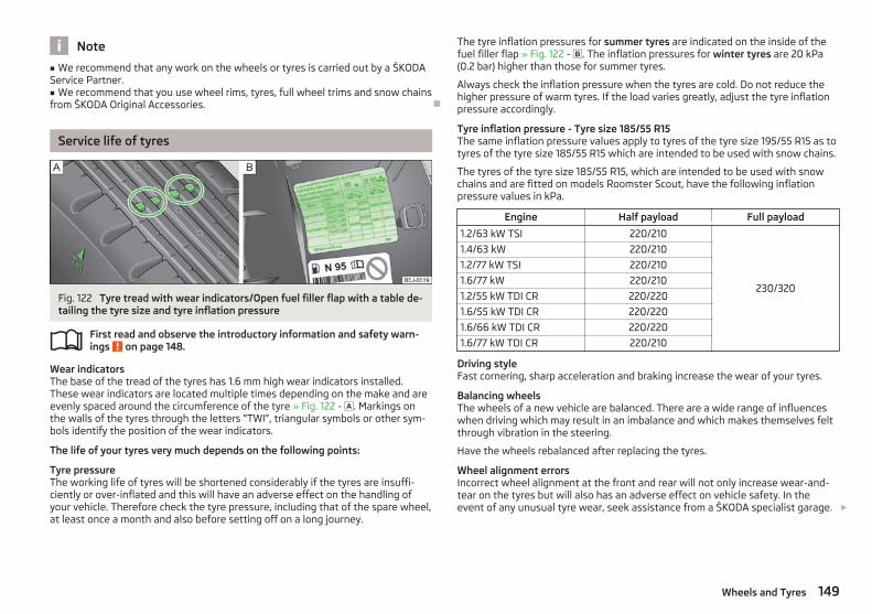
Note
■ We recommend that any work on the wheels or tyres is carried out by a ŠKODAService Partner.■ We recommend that you use wheel rims, tyres, full wheel trims and snow chainsfrom ŠKODA Original Accessories. Ð
Service life of tyres
Fig. 122 Tyre tread with wear indicators/Open fuel filler flap with a table de-tailing the tyre size and tyre inflation pressure
First read and observe the introductory information and safety warn-ings on page 148.
Wear indicatorsThe base of the tread of the tyres has 1.6 mm high wear indicators installed.These wear indicators are located multiple times depending on the make and areevenly spaced around the circumference of the tyre » Fig. 122 - . Markings onthe walls of the tyres through the letters “TWI”, triangular symbols or other sym-bols identify the position of the wear indicators.
The life of your tyres very much depends on the following points:
Tyre pressureThe working life of tyres will be shortened considerably if the tyres are insuffi-ciently or over-inflated and this will have an adverse effect on the handling ofyour vehicle. Therefore check the tyre pressure, including that of the spare wheel,at least once a month and also before setting off on a long journey.
ä
The tyre inflation pressures for summer tyres are indicated on the inside of thefuel filler flap » Fig. 122 - . The inflation pressures for winter tyres are 20 kPa(0.2 bar) higher than those for summer tyres.
Always check the inflation pressure when the tyres are cold. Do not reduce thehigher pressure of warm tyres. If the load varies greatly, adjust the tyre inflationpressure accordingly.
Tyre inflation pressure - Tyre size 185/55 R15The same inflation pressure values apply to tyres of the tyre size 195/55 R15 as totyres of the tyre size 185/55 R15 which are intended to be used with snow chains.
The tyres of the tyre size 185/55 R15, which are intended to be used with snowchains and are fitted on models Roomster Scout, have the following inflationpressure values in kPa.
Engine Half payload Full payload
1.2/63 kW TSI 220/210
230/320
1.4/63 kW 220/210
1.2/77 kW TSI 220/210
1.6/77 kW 220/210
1.2/55 kW TDI CR 220/220
1.6/55 kW TDI CR 220/220
1.6/66 kW TDI CR 220/220
1.6/77 kW TDI CR 220/210
Driving styleFast cornering, sharp acceleration and braking increase the wear of your tyres.
Balancing wheelsThe wheels of a new vehicle are balanced. There are a wide range of influenceswhen driving which may result in an imbalance and which makes themselves feltthrough vibration in the steering.
Have the wheels rebalanced after replacing the tyres.
Wheel alignment errorsIncorrect wheel alignment at the front and rear will not only increase wear-and-tear on the tyres but will also has an adverse effect on vehicle safety. In theevent of any unusual tyre wear, seek assistance from a ŠKODA specialist garage. £
149Wheels and Tyres

Tyre damageDrive over curbs on the side of the road and other such obstacles slowly and,where possible, at a right angle in order to avoid damage to tyres and wheeltrims.
We recommend checking your tyres and wheel rims for damage (punctures, cuts,splits and bulges, etc.) on a regular basis. Remove foreign bodies from the tyreprofile.
Unusual vibrations or pulling of the vehicle to one side could be a sign of tyredamage. If there is any doubt that a wheel is damaged, immediately reduce yourspeed and stop! Check the tyres for signs of damage (bulges, splits, etc.). If no ex-ternal damage is evident, drive slowly and carefully to the nearest ŠKODA special-ist garage to have the vehicle checked. Ð
Handling wheels and tyres
Fig. 123 Changing wheels around
First read and observe the introductory information and safety warn-ings on page 148.
Changing wheels aroundIf significantly greater wear is present on the front tyres, we recommend chang-ing the front wheels around with the rear wheels as shown in the dia-gram » Fig. 123. You will then obtain approximately the same life for all the tyres.
We recommend that you change the wheels around every 10 000 km in order toachieve even wear on all wheels and to obtain optimal tyre life.
Storing tyresMark wheels before removing them so that their previous direction of running canbe maintained when mounted them again.
ä
Always store wheels or tyres which been removed in a cool, dry and, where possi-ble, dark place. Tyres which are not fixed to a wheel trim should be stored up-right. Ð
New wheels and tyres
First read and observe the introductory information and safety warn-ings on page 148.
Only fit tyres of the same type, size (rolling circumference) and the same treadpattern on one axle on all 4 wheels.
The tyre/wheel combinations which are approved for your vehicle are indicated inyour vehicle documents.
Proper knowledge of the tyre data makes it easier for you to select the correcttype of tyre. Tyres, for example, have the following inscription on their walls.
185/65 R 14 86 T
What this means is:
185 Tyre width in mm
65 Height/width ratio in %
R Code letter for the type of tyre - Radial
14 Diameter of wheel in inches
86 Load index
T Speed symbol
The following speed restrictions apply to tyres.
Speed symbol Permissible maximum speed
Q 160 km/h
R 170 km/h
S 180 km/h
T 190 km/h
U 200 km/h
H 210 km/h
V 240 km/h
W 270 km/h £
ä
150 General Maintenance

The date of manufacture is also stated on the tyre wall (possibly only on the in-side of wheel): e.g.
DOT ... 20 12...
means, for example, that the tyre was manufactured in the 20th week of 2012.
The following must be observed if only one temporary spare wheel is availa-ble » page 151. Ð
Unidirectional tyres
First read and observe the introductory information and safety warn-ings on page 148.
The direction of rotation of the tyres is marked by arrows on the wall of the tyre.The so specified running direction must absolutely be complied with. Only thenare the tyres able to provide the optimal properties in terms of grip, low noise,wear-and-tear and aquaplaning.
If, in the event of a puncture, it is necessary to fit a spare wheel with a tyre with-out a dedicated running direction or the opposite running direction, drive carefullyas the optimum characteristics of the tyre are no longer applicable in this situa-tion. Ð
Spare wheel
Fig. 124 Boot: Spare wheel
First read and observe the introductory information and safety warn-ings on page 148.
The spare wheel is located in a well under the floor covering in the boot and isfixed in place with a special bolt » Fig. 124.
ä
ä
Before removing the spare wheel, the box containing the vehicle tool kit must beremoved.
It is important to check the inflation pressure in the spare wheel (preferably everytime the tyre air pressure is checked - see sticker on the fuel filler flap » page 149)to ensure it is always ready to use.
If the dimensions or design of the spare wheel differ from the tyres fitted to thevehicle (e.g. winter tyres or low-profile tyres), it must only be used briefly in theevent of a puncture and if an appropriately cautious style of driving is adop-ted » .
Replace it with a wheel having the appropriate mode and dimensions as soon aspossible
Temporary spare wheelA warning label is displayed on the wheel rim of the spare wheel to indicate thatyour vehicle is equipped with a temporary spare wheel.
Please observe the following when driving with a temporary spare wheel.› The warning label must not be covered after installing the wheel.› Do not drive faster than 80 km/h with the temporary spare wheel and pay par-
ticular attention while driving. Avoid accelerating at full throttle, sharp brakingand fast cornering.
› The inflation pressure for this spare wheel is identical to the maximum inflationpressure of the standard tyres.
› Only use this temporary spare wheel to reach the nearest ŠKODA specialist ga-rage as it is not intended for continuous use.
WARNING
■ Never use the temporary spare wheel if it is damaged.■ If the dimensions or design of the temporary spare wheel differ from the fit-ted tyres, never drive faster than 80 km/h (or 50 mph). Avoid accelerating atfull throttle, sharp braking and fast cornering.
CAUTION
Observe the instructions on the sticker on the temporary spare wheel.
Note
The tyre pressure should be at the highest pressure specified for your vehicle atall times. Ð
151Wheels and Tyres

Full wheel trim
First read and observe the introductory information and safety warn-ings on page 148.
Pulling off› Hook the clamp found in the vehicle tool kit into the reinforced edge of the
wheel trim.› Push the wheel wrench through the clamp, support on the tyre and pull off the
wheel trim.
Install› First press the full wheel trim onto the wheel rim at the valve opening provided.
Then press the full wheel trim into the wheel rim until its entire circumferencelocks correctly in place.
CAUTION
■ Use the pressure of your hand, do not knock the full wheel trim! Heavy knocksmainly on the points where the full wheel trim has not been inserted into thewheel, can result in damage to the guide and centring elements of the full wheeltrim.■ First of all check that the theft-deterrent wheel bolt is located in the hole nearthe valve before fitting the full wheel trim onto a steel wheel which is attachedwith a theft-deterrent wheel bolt » page 160, Securing wheels against theft.■ If wheel trims are retrofitted it must be ensured that an adequate flow of air isassured to cool the brake system. Ð
Wheel bolts
Fig. 125 Remove the cap
ä
First read and observe the introductory information and safety warn-ings on page 148.
Pulling off› Push the plastic clip sufficiently far onto the cap until the inner catches of the
clip are positioned at the collar of the cap and detach the cap » Fig. 125.
Install› Push the caps onto the wheel bolts up to the stop.
The wheel bolt caps are housed in a plastic box in the spare wheel or in the stor-age space for the spare wheel. Ð
Wheel trim caps
Fig. 126 Pull off the wheel trim cap onlight alloy wheels
First read and observe the introductory information and safety warn-ings on page 148.
Pulling off› Carefully remove the wheel trim cap using the wire clamp from the vehicle tool
kit » Fig. 126. Ð
ä
ä
152 General Maintenance

Tyre control display
Fig. 127 Button for setting the tyre infla-tion pressure control value
First read and observe the introductory information and safety warn-ings on page 148.
The tyre control display compares the speed and thus the rolling circumference ofthe individual wheels with the help of the ABS sensors. If the rolling circumfer-ence of a wheel is changed, the warning light in the instrument clus-ter » page 23, Tyre control display and an audible signal sounds.
The rolling circumference of the tyre can change if:› the tyre inflation pressure is too low;› the structure of the tyre is damaged;› the vehicle is loaded on one side;› the wheels of an axle are loaded heavily (e.g. when towing a trailer or when
driving uphill or downhill);› snow chains are mounted;› the temporary spare wheel is mounted;› one wheel per axle was changed.
Basic setting of the system
After changing the tyre inflation pressure, after changing one or several wheels,the position of a wheel on the vehicle (e.g. exchanging the wheels between theaxles) or when the warning light lights up while driving, a basic setting of the sys-tem must be carried out as follows:› Inflate all of the tyres to the specified inflation pressure » page 149, Service life
of tyres.› Switch on the ignition.
ä
› Press and hold the button » Fig. 127 for longer than 2 seconds. Whilepressing the button, the warning light illuminates. At the same time the sys-tem memory is erased and the new calibration is started, which is confirmedwith an audible signal and then the warning light goes out.
› If the warning light does not go out after the basic setting, this indicates asystem fault. Seek help from a ŠKODA specialist garage.
The warning light is litIf the tyre inflation pressure of at least one wheel is insufficiently inflated in com-parison to the stored basic value, the warning light » lights up.
The warning light flashesIf the warning light flashes, there is a system fault. Seek help from a ŠKODA spe-cialist garage to correct the fault.
WARNING
■ When the warning light illuminates, immediately reduce the speed andavoid sudden steering and brake manoeuvres. Stop the vehicle as soon aspossible and inspect the tyres and their inflation pressure.■ Under certain circumstances (e.g. sporty style of driving, wintry or unpavedroads) the warning light can be delayed or does not light up at all.■ The tyre control display does not absolve the driver of the responsibility toensure the correct tyre inflation pressure. For this reason, the tyre inflationpressure must be checked regularly.
Note
■ The tyre control display does therefore not replace the regular tyre inflationpressure control, as the system cannot detect an even loss of pressure.■ The tyre control display cannot provide a warning in the event of very rapid tyreinflation pressure loss, e.g. in the case of sudden tyre damage. In this case care-fully bring the vehicle to a standstill without sudden steering movements orsharp braking.■ To ensure a proper functioning of the tyre control display, it is necessary to re-peat the basic setting every 10 000 km or once a year. Ð
153Wheels and Tyres

Wheel bolts
First read and observe the introductory information and safety warn-ings on page 148.
Wheels and wheel bolts are matched to each other in terms of design. Each timeyou fit other wheels, e.g. light alloy wheels or wheels with winter tyres, you musttherefore also use the matching wheel bolts of the correct length and shape ofspherical cap. This is essential to ensure that the wheels are tightly fitted andthat the brake system operates properly. Ð
Winter tyres
First read and observe the introductory information and safety warn-ings on page 148.
The handling of your vehicle will be significantly improved when driving on wintryroads if you fit winter tyres. Summer tyres do not offer the same grip on ice, snowand at temperatures below 7 °C because of their construction (width, rubberblend, tread pattern).
To achieve the best possible handling properties, winter tyres must be fitted onall 4 wheels, the minimum tread depth must be 4 mm and tyres must be no olderthan 4 years.
Winter tyres of a lower speed category can be used provided that the permissiblemaximum speed of these tyres is not exceeded even if the possible maximumspeed of the vehicle is higher.
For the sake of the environment
Fit the summer tyres on again in good time as they provide better handling prop-erties, a shorter braking distance, less tyre noise, and reduced tyre wear on roadswhich are free of snow and ice as well as at temperatures above 7 °C. The fuelconsumption is also lower. Ð
Snow chains
First read and observe the introductory information and safety warn-ings on page 148.
Snow chains must only be mounted on the front wheels.
ä
ä
ä
When driving on wintry roads, snow chains improve not only traction, but also thebraking performance.
For technical reasons, it is only permissible to fit snow chains with the followingwheel/tyre combinations.
Wheel size Depth (D) Tyre size
5J x 14 35 mm 175/70
6J x 14 37 mm 185/65
6J x 15 43 mm 185/55
Only fit snow chains with links and locks not larger than 12 mm.
Remove the full wheel trims before installing the snow chains.
Observe the national legal regulations relating to the use of snow chains and themaximum vehicle speed with snow chains.
CAUTION
The chains must be removed when driving on roads which are free of snow. Theyadversely affect the handling of your vehicle, damage the tyres and are rapidlydestroyed. Ð
154 General Maintenance

Accessories, changes and replacement ofparts
Introductory information
If you want to retrofit the vehicle with accessories, if a vehicle part is to be re-placed with a new one, or when needing to make technical changes, the follow-ing instructions must be observed.
› Always seek advice from a ŠKODA Service Partner before purchasing any acces-sories or parts and before making any technical changes » .
› The guidelines and instructions issued by ŠKODA must be observed when mak-ing technical changes.
Adhering to the prescribed procedures will prevent any kind of damage to the ve-hicle, and its travelling and operating safety will be maintained. The vehicle alsocomplies with German road transport regulations (StVZO). More information isavailable from a ŠKODA Service Partner who can also perform the necessary workcorrectly.
Vehicles with special built-on typesTechnical documents regarding changes carried out on the vehicle must be keptby the vehicle user, in order to hand over later to the old car user. This ensuresthe recycling in accordance with environmental regulations.
Interference on the electronic components and their software can lead to opera-tional faults. This interference can also impair not directly affected systems be-cause of the networking of the electronic components. In other words, the vehi-cle's roadworthiness may be put at risk and increased wear on parts may arise.
Any damage caused by technical changes made without consent by ŠKODA is ex-cluded from the warranty – see the warranty certificate.
WARNING
■ Work or modifications on your vehicle, which have been carried out unpro-fessionally, can cause operational faults - risk of accident!■ We advise you, in your own interest, to only use ŠKODA Original Accessoriesand ŠKODA Original Parts which have been expressly approved for use onyour vehicle. Reliability, safety and suitability have been established forŠKODA Original Accessories and ŠKODA Original Parts.■ Although we constantly monitor the market, we are not able to assess orwarrant the parts even though in some instances such parts may have a typeapproval or may have been approved by a nationally recognised testing labo-ratory.
Note
ŠKODA Original Accessories and ŠKODA Original Parts can be purchased fromŠKODA Service Partners who will also professionally undertake the assembly ofthe purchased parts. Ð
Changes and impairments of the airbag system
Repairs and technical modifications must comply with ŠKODA guidelines.
We recommend that any modifications and repairs to the front bumper, doors,front seats, headliner or bodywork be carried out by a ŠKODA Service Partner.These vehicle parts may include system components for the airbag system.
WARNING
■ Airbag modules can not be repaired, but must be replaced.■ Never install any airbag parts into the vehicle that have been removed fromold cars or have been recycled.■ A modification to the suspension of the vehicle including the use of non-ap-proved rim-tyre combinations can alter the functioning of the airbag and in-crease the risk of serious or fatal injuries in an accident.■ Parts of the airbag system may be damaged when working on the airbagsystem or removing and installing system parts due to other repairs. This maymean that the airbags will not deploy properly or not at all in the event of anaccident. Ð
155Accessories, changes and replacement of parts

Do-it-yourself
Do-it-yourself
First-aid kit and warning triangle
Fig. 128 Placing of the warning triangle
A warning triangle with the maximum dimensions 39 x 68 x 450 mm can be at-tached to the trim panel of the rear wall with rubber straps » Fig. 128.
WARNING
The first-aid kit and warning triangle must always be secured safely so thatthey do not come loose when making an emergency braking or in a vehiclecollision which could cause injuries to occupants.
Note
■ Pay attention to the expiration date of the first-aid kit.■ We recommend using a first-aid box from ŠKODA Original Accessories availablefrom a ŠKODA Service Partner. Ð
Fire extinguisher
The fire extinguisher is attached with straps in a holder under the driver seat.
Please read carefully the instructions which are attached to the fire extinguish-er.
The fire extinguisher must be checked by an authorised person on an annual ba-sis (the national legal provisions must be observed).
WARNING
The fire extinguisher must always be secured safely so that they do not comeloose when making an emergency braking or in a vehicle collision which couldcause injuries to occupants.
Note
■ The fire extinguisher must comply with the relevant applicable national legal re-quirements.■ Pay attention to the expiration date of the fire extinguisher. If the fire extin-guisher is used after the expiration date, its proper function is no longer assured.■ The fire extinguisher is part of the scope of delivery in certain countries only. Ð
Vehicle tool kit
Fig. 129 Boot: Storage compartment forvehicle too kit
The vehicle tool kit and the lifting jack with sticker are housed in a plastic box inthe spare wheel » Fig. 129 or in the storage space for the spare wheel. There isalso space here for the removable ball rod for the trailer towing device. The box isattached with a strap on the spare wheel.
The vehicle tool kit contains the following parts (depending on equipment fitted):› wire clamps for removing the full wheel trims;› wheel wrench;› towing eye;› Adapter for anti-theft wheel bolts;› Extraction pliers for wheel bolt caps; £
156 Do-it-yourself

› Replacement bulb set;› Screwdriver.
Before placing the lifting jack back into its storage area, screw in the arm of thelifting jack fully.
WARNING
■ The factory-supplied lifting jack is only intended for your model of vehicle.Under no circumstances attempt to lift heavier vehicles or other loads - risk ofinjury!■ Ensure that the vehicle tool kit is safely secured in the boot.
Note
Ensure that the box is always secured with the strap. Ð
Changing a wheel
ä Introduction
This chapter contains information on the following subjects:
Preliminary work 157Changing a wheel 158Subsequent steps 158Loosening and tightening wheel bolts 159Raising the vehicle 159Securing wheels against theft 160
WARNING
■ If you are in flowing traffic, switch on the hazard warning light system andset up the warning triangle at the prescribed distance! The national legal re-quirements must be observed. In this way you are not only protecting yourselfbut other road users as well.■ If the wheel is damaged or in the event of a puncture, park the vehicle as faraway as possible from the flow of traffic. Park on as flat and firm a surface aspossible.
WARNING (Continued)
■ If the wheel has to be changed on a slope, first of all block the oppositewheel with a stone or similar object to prevent the vehicle from unexpectedlyrolling away.■ If the vehicle is subsequently fitted with tyres which are different to those itwas fitted with at the works, follow these guidelines » page 150, New wheelsand tyres.■ Always raise the vehicle with the doors closed.■ Never position any body parts, such as arms or legs under the vehicle, whilethe vehicle is raised with a lifting jack.■ Secure the base plate of the lifting jack with suitable means to prevent pos-sible moving. A soft and slippery ground under the base plate may move thelifting jack, causing the vehicle to fall down. It is therefore always necessary toplace the lifting jack on a solid surface or use a wide and stable base. Use anon-slip base (e.g. a rubber foot mat) if the surface is smooth, such as cobbledstones, tiled floor, etc.■ Never start the engine with the vehicle sitting on the raised jack - danger ofsuffering injury.■ Only attach the lifting jack to the attachment points provided for this pur-pose.
CAUTION
■ The prescribed tightening torque of the wheel bolts for steel and light alloywheels is 120 Nm.■ If the anti-theft wheel bolt is fastened too tightly, it can cause damage to theanti-theft wheel bolt and adapter.
Note
■ The anti-theft wheel bolt set and adapter can be purchased from a ŠKODA Serv-ice Partner.■ The national legal requirements must be observed when changing a wheel. Ð
Preliminary work
First read and observe the introductory information and safety warn-ings on page 157.
The following steps must be carried out before actually changing the wheel: £
ä
157Do-it-yourself

› In the event of a puncture, park the vehicle as far away as possible from theflow of traffic. The place you choose should be level.
› Let all of the occupants get out. While changing a tyre, the occupants of thevehicle should not stand on the road (instead they should remain behind a crashbarrier).
› Switch off the engine and move the gearshift lever into Neutral or move theselector lever for the automatic gearbox into position P.
› Firmly apply the handbrake.› If a trailer is connected, remove it.› Remove the vehicle tool kit » page 156 and the spare wheel » page 151, Spare
wheel from the boot. Ð
Changing a wheel
First read and observe the introductory information and safety warn-ings on page 157.
Always change a wheel on a level surface as far as possible.› Remove the full wheel trim » page 152 or caps » page 152.› In the case of light alloy wheel rims remove the wheel trim cap » page 152.› First of all slacken the anti-theft wheel bolt and then the other wheel
bolts » page 159.› Jack up the vehicle until the wheel that needs changing is clear of the
ground » page 159.› Unscrew the wheel bolts and place them on a clean surface (cloth, paper, etc.).› Remove the wheel.› Attach the spare wheel and slightly screw on the wheel bolts.› Lower the vehicle.› Alternately tighten the wheel bolts opposite each other using the wheel
wrench (crosswise) and then tighten the anti-theft wheel bolt » page 159.› Reinstall the wheel trim/wheel trim cap or the caps.
Note
■ All bolts must be clean and must turn easily.■ Under no circumstances grease or oil the wheel bolts!■ When fitting unidirectional tyres, ensure that the direction of rotation is cor-rect » page 148. Ð
ä
Subsequent steps
First read and observe the introductory information and safety warn-ings on page 157.
The following steps must also be performed after changing the wheel.› Stow and attach the replaced wheel in the spare wheel well using a special
screw » page 151, Spare wheel.› Stow the vehicle tool kit in the space provided.› Check the tyre pressure on the installed spare wheel as soon as possible.› Have the tightening torque of the wheel bolts checked with a torque wrench
as soon as possible.› Change the damaged wheel or consult a ŠKODA specialist garage about repair
possibilities.
Note
■ If it is determined that the wheel bolts are corroded and difficult to turn whenchanging the wheel, the bolts must be replaced before checking the tighteningtorque.■ Drive cautiously and only at a moderate speed until the tightening torque hasbeen checked. Ð
ä
158 Do-it-yourself
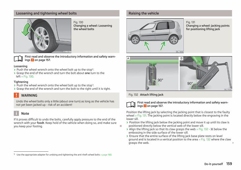
Loosening and tightening wheel bolts
Fig. 130 Changing a wheel: Looseningthe wheel bolts
First read and observe the introductory information and safety warn-ings on page 157.
Loosening› Push the wheel wrench onto the wheel bolt up to the stop1).› Grasp the end of the wrench and turn the bolt about one turn to the
left » Fig. 130.
Tightening› Push the wheel wrench onto the wheel bolt up to the stop1 ).› Grasp the end of the wrench and turn the bolt to the right until it is tight.
WARNING
Undo the wheel bolts only a little (about one turn) as long as the vehicle hasnot yet been jacked up - risk of an accident!
Note
If it proves difficult to undo the bolts, carefully apply pressure to the end of thewrench with your foodt. Keep hold of the vehicle when doing so, and make sureyou keep your footing. Ð
ä
Raising the vehicle
Fig. 131 Changing a wheel: Jacking pointsfor positioning lifting jack
Fig. 132 Attach lifting jack
First read and observe the introductory information and safety warn-ings on page 157.
Position the lifting jack by selecting the jacking point that is closest to the faultywheel » Fig. 131. The jacking point is located directly below the engraving in thelower sill.› Position the lifting jack below the jacking point and move it up until its claw is
positioned directly below the vertical web of the lower sill.› Align the lifting jack so that its claw grasps the web » Fig. 132 - below the
embossing in the side surface of the lower sill.› Ensure that the entire surface of the lifting jack base plate rests on level
ground and is located in a vertical position to the area » Fig. 132 where the clawgrasps the web. £
ä
1) Use the appropriate adapter for undoing and tightening the anti-theft wheel bolts » page 160.
159Do-it-yourself

› Continue turning up the jack until the wheel is just about lifted off the ground. Ð
Securing wheels against theft
Fig. 133 Principle sketch: Anti-theftwheel bolt with adapter
First read and observe the introductory information and safety warn-ings on page 157.
The anti-theft wheel bolts on vehicles fitted with them (one anti-theft wheel boltper wheel) can only be loosened or tighten up by using the adapter provided.› Pull off the full wheel trim from the wheel rim or the cap from the anti-theft
wheel bolt.› Insert the adapter B » Fig. 133 with its toothed side fully into the inner tooth-
ing of the safety wheel bolt A until the stop so that only the outer hexagon isjutting out.
› Push the wheel wrench onto the adapter B up to the stop.› Loosen or tighten the wheel bolt » page 159.› After removing the adapter, reinstall the full wheel trim or place the cap onto
the anti-theft wheel bolt.› Have the tightening torque checked with a torque wrench as soon as possible.
It is advisable to make a note of the code number hammered into the rear side ofthe adapter or the rear side of the anti-theft wheel bolt. This number can be usedto purchase a replacement adapter from a ŠKODA Service Partner, if necessary.
We recommend that you always carry the adapter for the wheel bolts with you inthe vehicle. It should be stowed in the vehicle tool kit. Ð
ä
Breakdown kit
ä Introduction
This chapter contains information on the following subjects:
Components of the breakdown kit 161Preparing to use the breakdown kit 161Sealing and inflating tyres 162Check after driving for 10 minutes 162
The breakdown kit is located in a box under the floor covering in the boot.
Use the breakdown kit to reliably repair tyre damage caused by foreign bodies ora puncture with diameters up to approx. 4 mm. Do not remove foreign bodies, e.g.screws or nails, from the tyre!
The repair can be undertaken on the vehicle immediately.
Repairs with the breakdown kit do not in any way replace a permanent repair ofthe tyre, it only serves to reach the next ŠKODA specialist garage.
The breakdown kit must not be used under the following circumstances:› if there is damage to the wheels;› in outside temperatures of less than -20 °C;› with tears or punctures greater than 4 mm in size;› if there is damage to the tyre wall;› when driving with very low tyre pressure or with a completely flat tyre;› if the use-by-date (see inflation bottle) has passed.
WARNING
■ If you are in flowing traffic, switch on the hazard warning light system andset up the warning triangle at the prescribed distance! The national legal re-quirements must be observed. In this way you are not only protecting yourselfbut other road users as well.■ If the wheel is damaged or in the event of a puncture, park the vehicle as faraway as possible from the flow of traffic. Park on as flat and firm a surface aspossible.■ A tyre filled with sealant has the same driving characteristics as a standardtyre. £
160 Do-it-yourself

WARNING (Continued)
■ Do not drive faster than 80 km/h (50 mph).■ Avoid accelerating at full throttle, sharp braking and fast cornering.■ Check the tyre inflation pressure after driving for 10 minutes!■ The sealant is hazardous to heath. Remove immediately if it comes into con-tact with the skin.
For the sake of the environment
Used sealant or sealant whose expiry date has passed must be disposed of in ac-cordance with environmental protection regulations.
Note
■ Observe the manufacturer's usage instructions for the breakdown kit.■ A new bottle of sealant can be purchased from ŠKODA Original Accessories.■ Immediately replace the wheel that was repaired using the breakdown kit orconsult a ŠKODA specialist garage about repair possibilities. Ð
Components of the breakdown kit
Fig. 134 Components of the breakdown kit
First read and observe the introductory information and safety warn-ings on page 160.ä
The breakdown kit contains the following parts:
Valve removerSticker with speed designation “max. 80 km/h”/“max. 50 mph”Inflation hose with plugAir compressorTyre inflation hoseTyre inflation pressure indicatorAir release valveON and OFF switch12 volt cable connectorTyre inflator bottle with sealing agentReplacement valve core
The valve remover 1 has a slot at its lower end which fits into the valve core.This is the only way in which you can remove and re-install the valve core fromthe tyre valve. The same also applies to the replacement valve core 11 . Ð
Preparing to use the breakdown kit
First read and observe the introductory information and safety warn-ings on page 160.
The following preparatory work must be carried out before using the breakdownkit.› In the event of a puncture, park the vehicle as far away as possible from the
flow of traffic. Park on as flat and firm a surface as possible.› Let all of the occupants get out. While changing a tyre, the occupants of the
vehicle should not stand on the road (instead they should remain behind a crashbarrier).
› Switch off the engine and move the gearshift lever into Neutral or move theselector lever for the automatic gearbox into position P.
› Firmly apply the handbrake.› Check that you can carry out the repairs with the breakdown kit » page 160.› If a trailer is connected, remove it.› Remove the breakdown kit from the boot.› Stick the sticker 2 » Fig. 134 on page 161 on the dash panel in view of the driv-
er.› Do not remove the foreign body, e.g. screw or nail, from the tyre.› Unscrew the valve cap. £
1
2
3
4
5
6
7
8
9
10
11
ä
161Do-it-yourself

› Use the valve remover 1 to unscrew the valve core and place it on a clean sur-face (rag, paper, etc.). Ð
Sealing and inflating tyres
First read and observe the introductory information and safety warn-ings on page 160.
Sealing› Forcefully shake the tyre inflator bottle 10 » Fig. 134 on page 161 several times.› Firmly screw the inflation hose 3 onto the tyre inflator bottle 10 in a clockwise
direction. The film on the cap is pierced automatically.› Remove the plug from the inflation hose 3 and plug the open end fully onto
the tyre valve.› Hold the bottle 10 with the bottom facing upwards and fill all of the sealing
agent from the tyre inflator bottle into the tyre.› Remove the empty tyre inflator bottle from the valve.› Screw the valve core back into the tyre valve using the valve remover 1 .
Inflating› Screw the tyre inflation hose 5 » Fig. 134 on page 161 of the air compressor
firmly onto the tyre valve.› Check that the air release valve 7 is closed.› Start the engine and run it in idle.› Plug the connector 9 into 12 Volt socket » page 61, 12-volt power socket.› Switch on the air compressor with the ON and OFF switch 8 .› Allow the air compressor to run until a pressure of 2.0 - 2.5 bar is achieved.
Maximum run time of 8 minutes » !› Switch off the air compressor.› If you cannot reach an air pressure of 2.0 – 2.5 bar, unscrew the tyre inflation
hose 5 from the tyre valve.› Drive the vehicle 10 metres forwards or backwards to allow the sealing agent to
“distribute” in the tyre.› Firmly screw the tyre inflation hose 5 back onto the tyre valve and repeat the
inflation process.› If you cannot reach the required tyre inflation pressure here either, this means
the tyre has sustained too much damage. You cannot seal with tyre with thebreakdown kit » .
› Switch off the air compressor.› Remove the tyre inflation hose 5 from the tyre valve.
Once a tyre inflation pressure of 2.0 – 2.5 bar is achieved, continue the journey ata maximum speed of 80 km/h (50 mph).
ä
Check the tyre inflation pressure after driving for 10 minutes » page 162.
WARNING
■ During inflation, the tyre inflation hose and air compressor may get hot- riskof injury!■ Do not place the hot tyre inflation hose or hot air compressor on flammablematerials - risk of fire!■ If you cannot inflate the tyre to at least 2.0 bar, this means the damage sus-tained was too serious. The sealing agent cannot be used to seal the tyre. Donot drive the vehicle. Get professional assistance!
CAUTION
Switch off the air compressor after running 8 minutes at the latest - danger ofoverheating! Allow the air compressor to cool a few minutes before switching iton again. Ð
Check after driving for 10 minutes
First read and observe the introductory information and safety warn-ings on page 160.
Check the tyre inflation pressure after driving for 10 minutes!
If the tyre inflation pressure is 1.3 bar or less:› Do not drive the vehicle! You cannot properly seal with tyre with the break-
down kit.› Get professional assistance.
If the tyre inflation pressure is 1.3 bar or more:› Adjust the tyre inflation pressure to the correct value (see inside of fuel filler
cap).› Continue driving carefully to the nearest ŠKODA specialist garage at a maxi-
mum speed of 80 km/h (50 mph). Ð
ä
162 Do-it-yourself

Jump-starting
ä Introduction
This chapter contains information on the following subjects:
Jump-starting 163Jump-starting in vehicles with the START-STOP system 164
The battery of another vehicle can be used to jump-start your vehicle if the en-gine will not start because the battery is flat. Jump-start cables are required forthis purpose.
Both batteries must have a rated voltage of 12 V. The capacity (Ah) of the batterysupplying the power must not be significantly less than the capacity of the dis-charged battery in your vehicle.
Jump-start cablesOnly use jump-start cables which have an adequately large cross-section and in-sulated terminal clamps. Observe the manufacturer's instructions.
Positive cable - colour coding in the majority of cases is red.
Negative cable - colour coding in the majority of cases is black.
WARNING
■ A discharged vehicle battery may already freeze at temperatures just below0 °C. In case of frozen battery carry out no jump-starting - risk of explosion!■ Pay attention to the warning instructions relating to working in the enginecompartment » page 136, Engine compartment.■ The non-insulated parts of the terminal clamps must never make contactwith each other. In addition, the jump-start cable connected to the positiveterminal of the battery must not come into contact with electrically conduct-ing parts of the vehicle - risk of short circuit!■ Do not clamp the jump-start cable to the negative terminal of the dis-charged battery. There is the risk of detonating gas seeping out the batterybeing ignited by the strong spark which results from the engine being started.■ Route the jump-start cables so that they cannot be caught by any rotatingparts in the engine compartment.■ Do not bend over the battery - risk of caustic burns!■ The vent screws of the battery cells must be tightened firmly.
WARNING (Continued)
■ Keep any sources of ignition (naked flame, smouldering cigarettes, etc.)away from the battery - risk of an explosion!■ Never jump-start vehicle batteries with an electrolyte level that is too low -risk of explosion and caustic burns.
Note
■ There must not be any contact between the two vehicles otherwise currentmay flow as soon as the negative terminals are connected.■ The discharged battery must be properly connected to the system of the vehi-cle.■ We recommend you buy jump-start cables from a car battery specialist. Ð
Jump-starting
Fig. 135 Jump-starting using the batteryfrom another vehicle: A - flat ve-hicle battery, B - battery provid-ing current
First read and observe the introductory information and safety warn-ings on page 163.
The jump-start cables must be attached in the following sequence.
Connecting positive terminals› Attach one end 1 » Fig. 135 to the positive terminal of the discharged battery
A .› Attach the other end 2 to the positive terminal of the battery supplying the
power B .
Connecting negative terminal and engine block› Attach one end 3 » Fig. 135 to the negative terminal of the battery supplying
the power B . £
ä
163Do-it-yourself
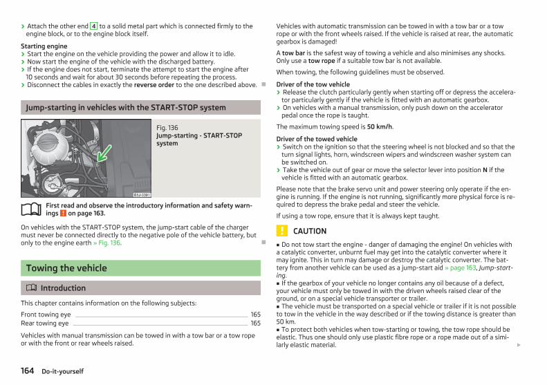
› Attach the other end 4 to a solid metal part which is connected firmly to theengine block, or to the engine block itself.
Starting engine› Start the engine on the vehicle providing the power and allow it to idle.› Now start the engine of the vehicle with the discharged battery.› If the engine does not start, terminate the attempt to start the engine after
10 seconds and wait for about 30 seconds before repeating the process.› Disconnect the cables in exactly the reverse order to the one described above. Ð
Jump-starting in vehicles with the START-STOP system
Fig. 136 Jump-starting - START-STOPsystem
First read and observe the introductory information and safety warn-ings on page 163.
On vehicles with the START-STOP system, the jump-start cable of the chargermust never be connected directly to the negative pole of the vehicle battery, butonly to the engine earth » Fig. 136. Ð
Towing the vehicle
ä Introduction
This chapter contains information on the following subjects:
Front towing eye 165Rear towing eye 165
Vehicles with manual transmission can be towed in with a tow bar or a tow ropeor with the front or rear wheels raised.
ä
Vehicles with automatic transmission can be towed in with a tow bar or a towrope or with the front wheels raised. If the vehicle is raised at rear, the automaticgearbox is damaged!
A tow bar is the safest way of towing a vehicle and also minimises any shocks.Only use a tow rope if a suitable tow bar is not available.
When towing, the following guidelines must be observed.
Driver of the tow vehicle› Release the clutch particularly gently when starting off or depress the accelera-
tor particularly gently if the vehicle is fitted with an automatic gearbox.› On vehicles with a manual transmission, only push down on the accelerator
pedal once the rope is taught.
The maximum towing speed is 50 km/h.
Driver of the towed vehicle› Switch on the ignition so that the steering wheel is not blocked and so that the
turn signal lights, horn, windscreen wipers and windscreen washer system canbe switched on.
› Take the vehicle out of gear or move the selector lever into position N if thevehicle is fitted with an automatic gearbox.
Please note that the brake servo unit and power steering only operate if the en-gine is running. If the engine is not running, significantly more physical force is re-quired to depress the brake pedal and steer the vehicle.
If using a tow rope, ensure that it is always kept taught.
CAUTION
■ Do not tow start the engine - danger of damaging the engine! On vehicles witha catalytic converter, unburnt fuel may get into the catalytic converter where itmay ignite. This in turn may damage or destroy the catalytic converter. The bat-tery from another vehicle can be used as a jump-start aid » page 163, Jump-start-ing.■ If the gearbox of your vehicle no longer contains any oil because of a defect,your vehicle must only be towed in with the driven wheels raised clear of theground, or on a special vehicle transporter or trailer.■ The vehicle must be transported on a special vehicle or trailer if it is not possibleto tow in the vehicle in the way described or if the towing distance is greater than50 km.■ To protect both vehicles when tow-starting or towing, the tow rope should beelastic. Thus one should only use plastic fibre rope or a rope made out of a simi-larly elastic material. £
164 Do-it-yourself

■ One should be constantly vigilant not to allow impermissibly high towing forcesor jerky loadings. There is always a risk of excessive stresses and damage result-ing at the points to which you attach the tow rope or tow bar when you attemptto tow a vehicle which is not standing on a paved road.■ Attach the tow rope or the tow bar to the towing eyes or to the detachable ballhead of the towing device » page 165 or » page 165.
Note
■ We recommend using a tow rope from ŠKODA Original Accessories availablefrom a ŠKODA Service Partner.■ Towing another vehicle requires a certain amount of practice. Both driversshould be familiar with the particular points about towing a vehicle. Unskilleddrivers should not attempt to tow in another vehicle or to be towed in.■ When towing, respect the national legal provisions, especially those which re-late to the identification of the towing vehicle and the vehicle being towed.■ The tow rope must not be twisted as it may in certain circumstances result inthe front towing eye being unscrewed out of your vehicle. Ð
Front towing eye
Fig. 137 Front bumper: Cap/installing the towing eye
First read and observe the introductory information and safety warn-ings on page 164.
Remove the cap carefully as follows.› Press on the left half of the cap in the area of the arrow » Fig. 137 - .› Remove the cap from the front bumper.
ä
› Screw in the towing eye by hand to the left up to the stop » Fig. 137 - . Fortightening purposes, we recommend, for example, using the wheel wrench,towing eye from another vehicle or a similar object that can be pushed throughthe eye.
› In order to reinstall the cap after screwing out the towing eye, insert it in themounts and then press on the right side of the cap. The cap must engage firmly.
CAUTION
The towing eye must always be screwed in fully and firmly tightened, otherwisethe towing eye can tear when towing in or tow-starting. Ð
Rear towing eye
Fig. 138 Rear towing eye
First read and observe the introductory information and safety warn-ings on page 164.
The rear towing eye is located below the rear bumper on the right » Fig. 138. Ð
ä
165Do-it-yourself

Fuses and light bulbs
Fuses
ä Introduction
This chapter contains information on the following subjects:
Fuses in the dash panel 167Fuses in the engine compartment 168
Individual electrical circuits are protected by fuses.
› Before replacing a fuse, switch off the ignition and the appropriate consumer› Find out which fuse belongs to the component that is not operat-
ing » page 167, Fuses in the dash panel or » page 168, Fuses in the enginecompartment.
› Take the plastic clip out of its fixture in the cover of the fuse box, place it on therelevant fuse and pull it out.
› A blown fuses is recognisable by the molten metal strip. Replace the faulty fusewith a new one of the same amperage.
Colour coding of fusesColour Maximum amperage
light brown 5
dark brown 7.5
red 10
blue 15
yellow 20
white 25
green 30
WARNING
Always read and observe the warnings before completing any work in the en-gine compartment » page 136, Engine compartment.
CAUTION
■ Never “repair” fuses and also do not replace them with a fuse of a higher am-perage - risk of fire! This may also cause damage at another part of the electricalsystem.■ Have the electrical system checked as quickly as possible by a ŠKODA specialistgarage if a newly inserted fuse blows again after a short time.
Note
■ We recommend always carrying replacement fuses in the vehicle. A box of re-placement fuses can be purchased from ŠKODA Original Accessories.■ Multiple fuses may exist for a single power consuming device.■ Multiple power consuming devices can share a single fuse. Ð
166 Do-it-yourself

Fuses in the dash panel
Fig. 139 Underside of the dash panel:Distribution board cover.
Fig. 140 Schematic representation of the fuse box for vehicles with left-hand steering/right-hand steering
First read and observe the introductory information and safety warn-ings on page 166.
The fuses are located on the left side of the dash panel behind a cover.
› Carefully remove the cover in the direction of the arrow » Fig. 139.› After the fuse has been replaced, replace the cover in the dash panel in the op-
posite direction of the arrow so that the guide lugs are guided into the open-ings of the dash panel. Close the cover until it clicks into place.
Fuse assignment in the dash panelNo. Power consumer
1 S-contact
2 START-STOP, air-conditioning system
3 Instrument cluster, headlamp beam adjustment
ä
No. Power consumer
4 Control unit for ABS, button for START STOP
5 Petrol engine: Speed regulating system
6 Reversing light (manual gearbox)
7 Ignition, engine control unit, automatic gearbox
8 Brake pedal switch, clutch pedal switch
9Operating controls for the heating, control unit for air conditioning sys-tem, parking aid, control unit for cornering lights, radiator fan, washingnozzles
10 Windscreen Wiper and Washer System
11 Mirror adjustment
12 Control unit for trailer detection
13 Control unit for automatic gearbox
14 Motor for halogen projector headlights with cornering light function
15 PDA navigation system
16 Electrohydraulic power steering
17 START-STOP (radio), daylight driving light
18 Mirror heater
19 S-contact
20 Alarm
21 Reversing light, fog lights with the function CORNER
22Operating controls for the heating, control unit for air conditioning sys-tem, parking aid, mobile phone, instrument cluster, steering anglesender, ESC, vehicle voltage control unit, multifunction steering wheel
23Interior lighting, storage compartment and luggage compartment, sidelights
24 Central control unit
25 Seat heaters
26 Rear window wiper
27 Telephone preinstallation
28 Petrol engine: AKF valve, Diesel engine: Control flap
29 Injection, coolant pump
30 Fuel pump, ignition, Cruise control system, operation of PTC relay
31 Lambda probe £
167Fuses and light bulbs
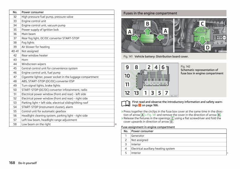
No. Power consumer
32 High pressure fuel pump, pressure valve
33 Engine control unit
34 Engine control unit, vacuum pump
35 Power supply of ignition lock
36 Main beam
37 Rear fog light, DC/DC converter START-STOP
38 Fog lights
39 Air blower for heating
40-41 Not assigned
42 Rear window heater
43 Horn
44 Windscreen wipers
45 Central control unit for convenience system
46 Engine control unit, fuel pump
47 Cigarette lighter, power socket in the luggage compartment
48 ABS, START-STOP (DC/DC) converter ESP
49 Turn signal lights, brake lights
50 START-STOP (DC/DC) converter infotainment, radio
51 Electrical power window (front and rear) - left side
52 Electrical power window (front and rear) - right side
53 Parking light = left side, electrical sliding/tilting roof
54 START-STOP (instrument cluster), alarm
55 Control unit for automatic gearbox
56 Headlight cleaning system, parking light - right side
57 Left low beam, headlight range adjustment
58 Low beam on the right Ð
Fuses in the engine compartment
Fig. 141 Vehicle battery: Distribution board cover.
Fig. 142 Schematic representation offuse box in engine compartment
First read and observe the introductory information and safety warn-ings on page 166.
› Press together the circlips in the fuse box cover at the same time in the direc-tion of arrow A » Fig. 141 and remove the cover in the direction of arrow B .
› Release the fixtures in the openings C using a flat screwdriver and fold thecover upwards in direction of arrow D .
Fuse assignment in engine compartmentNo. Power consumer
1 Generator
2 Not assigned
3 Interior
4 Electrical auxiliary heating system
5 Interior £
ä
168 Do-it-yourself

No. Power consumer
6 Glow plugs, radiator fan
7 Electrohydraulic power steering
8 ABS or TCS or ESC
9 Radiator fan
10 Automatic gearbox
11 ABS or TCS or ESC
12 Central control unit
13 Electrical auxiliary heating system
Note
Fuses 1 - 7 are replaced by a specialist ŠKODA garage. Ð
Bulbs
ä Introduction
This chapter contains information on the following subjects:
Headlights 170Replacing a bulb for low beam and main beam (halogen headlights) 170Replacing the bulb for the low beam (Halogen projector headlights) 171Replacing the bulb for the main beam (Halogen projector headlights) 171Changing the bulb for the front turn signal light 171Changing the light bulb for the front parking light 171Fog lights and daytime running lights 172Fog lights - Roomster Scout 172Changing the bulb for the licence plate light 173Tail lamp assembly 173
Some manual skills are required to change a bulb. For this reason, if uncertain, werecommend that bulbs are replaced by a ŠKODA specialist garage or other experthelp is sought.
› Switch off the ignition and all of the lights before replacing a bulb.› Faulty bulbs must only be replaced with the same type of bulbs. The designa-
tion is located on the light socket or the glass bulb.› A stowage compartment for replacement bulbs is located in a plastic box in the
spare wheel or underneath the floor covering in the boot.
WARNING
■ Accidents can be caused if the road in front of the vehicle is not sufficientlyilluminated and the vehicle cannot or can only be seen with difficulty by otherroad users.■ Always read and observe the warnings before completing any work in theengine compartment » page 136, Engine compartment.■ Bulbs H7 and H4 are pressurised and may burst when changing the bulb -risk of injury! We therefore recommended wearing gloves and safety glasseswhen changing a bulb.
CAUTION
■ Do not take hold of the glass bulb with naked fingers (even the smallestamount of dirt reduces the working life of the light bulb). Use a clean cloth, nap-kin, or similar.■ When removing and installing the tail light make sure that the paintwork of thevehicle and the tail light are not damaged.
Note
■ This Owner's Manual only describes the replacement of bulbs where it is possi-ble to replace the bulbs on your own without any complications arising. Otherlight bulbs should be changed by a ŠKODA specialist garage.■ We recommend that a box of replacement bulbs be always carried in the vehi-cle. Replacement bulbs can be purchased from ŠKODAOriginal Accessories.■ We recommend that the headlight settings are checked by a ŠKODA specialistgarage after replacing a bulb in the main or low beam.■ LED diodes should be changed by a specialist ŠKODA garage. Ð
169Fuses and light bulbs

Headlights
Fig. 143 Bulb arrangement: Halogen headlights/halogen projector head-lights
First read and observe the introductory information and safety warn-ings on page 169.
Bulb arrangement in the Halogen headlampA - low beam, main beam and side lights
B - front turn signal light
Bulb arrangement in the Halogen projector headlights1 - low beam light
2 - main beam and side lights
3 - front turn signal light Ð
ä
Replacing a bulb for low beam and main beam (halogenheadlights)
Fig. 144 Removing bulbs for low andmain beam
First read and observe the introductory information and safety warn-ings on page 169.
› Remove the rubber cover A » Fig. 143 on page 170.› Remove the connector on the bulb, unlock the circlip, and remove the light
bulb » Fig. 144.› Insert a new light bulb in such a way that the fixing lugs of the bulb socket fit in
the recesses of the reflector.› Lock the circlip and insert the connector in the bulb.› Insert the rubber cover. Ð
ä
170 Do-it-yourself
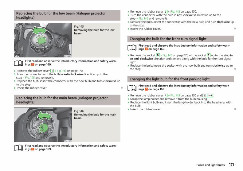
Replacing the bulb for the low beam (Halogen projectorheadlights)
Fig. 145 Removing the bulb for the lowbeam
First read and observe the introductory information and safety warn-ings on page 169.
› Remove the rubber cover 1 » Fig. 143 on page 170.› Turn the connector with the bulb in anti-clockwise direction up to the
stop » Fig. 145 and remove it.› Replace the bulb, insert the connector with the new bulb and turn clockwise up
to the stop.› Insert the rubber cover. Ð
Replacing the bulb for the main beam (Halogen projectorheadlights)
Fig. 146 Removing the bulb for the mainbeam
First read and observe the introductory information and safety warn-ings on page 169.
ä
ä
› Remove the rubber cover 2 » Fig. 143 on page 170.› Turn the connector with the bulb in anti-clockwise direction up to the
stop » Fig. 146 and remove it.› Replace the bulb, insert the connector with the new bulb and turn clockwise up
to the stop.› Insert the rubber cover. Ð
Changing the bulb for the front turn signal light
First read and observe the introductory information and safety warn-ings on page 169.
› Remove the socket B » Fig. 143 on page 170 or the socket 3 up to the stop inan anti-clockwise direction and remove along with the bulb for the turn signallight.
› Replace the bulb, insert the socket with the new bulb and turn clockwise up tothe stop. Ð
Changing the light bulb for the front parking light
First read and observe the introductory information and safety warn-ings on page 169.
› Remove the rubber cover A » Fig. 143 on page 170 and 2 . 2nd .› Grasp the lamp holder and remove it from the bulb housing.› Replace the light bulb and insert the lamp holder back into the headlamp with
the bulb.› Insert the rubber cover. Ð
ä
ä
171Fuses and light bulbs

Fog lights and daytime running lights
Fig. 147 Front bumper: Protective grille/removing the fog light
First read and observe the introductory information and safety warn-ings on page 169.
Bulb arrangement » Fig. 147.
A - Bulb for daylight driving light
B - Light bulb for fog lights
Removing the cap› Grasp the protective grille in the areas marked by the arrows » Fig. 147 - and
remove the cover.
Replacing light bulbs for fog lights/daytime running lights› Insert your hand into the opening in the protective grille and press the
catch » Fig. 147 - in the direction of the arrow.› Remove the front fog lamp.› Turn the connector with the bulb in counter-clockwise up to the stop and re-
move.› Replace the lamp, insert the connector with the new bulb and turn clockwise
up to the stop.› To re-install the fog light, first of all place the fog light with the lug on the side
opposite the licence plate.› Press in the fog lamp on the side closest to the licence plate.› Insert the cap, beginning with the lug on the side opposite the license plate.› Press in the cap on the side facing the license plate. The cap must engage firm-
ly. Ð
ä
Fog lights - Roomster Scout
Fig. 148 Front bumper: Roomster Scout
Fig. 149 Front bumper: Fog lights/fog lights: Replacing the light bulb
First read and observe the introductory information and safety warn-ings on page 169.
Removing the cap and fog light› Guide the wire clamp » Fig. 148 into the opening above the fog light » page 156,
Vehicle tool kit and remove the cover.› Use the screwdriver » page 156, Vehicle tool kit to remove the screws » Fig. 149
- .› Remove the front fog lamp.
Changing light bulbs and installing fog lights› Press the locking button 1 » Fig. 149 of the plug A and remove the plug from
the socket B .› Turn the socket B with the bulb counter-clockwise up to the stop and remove.› Replace the bulb, insert the socket with the new bulb and turn clockwise up to
the stop. £
ä
172 Do-it-yourself

› Insert the plug A into the socket B .› Retighten the screws and insert the cap. The cap must engage firmly. Ð
Changing the bulb for the licence plate light
Fig. 150 Remove the licence plate light
First read and observe the introductory information and safety warn-ings on page 169.
› Open the luggage compartment door and unscrew the glass cover » Fig. 150.› Remove the faulty bulb from the holder and insert a new one.› Replace the glass cover and push in until the stop. Make sure that you install
the rubber seal in the right direction.› Slightly screw the glass cover. Ð
Tail lamp assembly
Fig. 151 Removing the tail light assembly/disconnecting the plug connection
ä
Fig. 152 Remove the middle part of the light/bulb arrangement
First read and observe the introductory information and safety warn-ings on page 169.
Bulb arrangement in the tail light assembly » Fig. 152
1 - Brake lights
2 - Turn signal lights
3 - Reversing light
4 - Rear fog light
5 - parking lights
Removing and installing the tail light› Open the boot lid.› Unscrew the light » Fig. 151 - .› Grip the light in the upper and lower area and move backwards somewhat.› Disconnect plug connection » Fig. 151 - .› To access the bulbs, unscrew the middle of the light and press off the latching
mechanism » Fig. 152 - .› To reinstall, screw the middle part of the light onto the housing of the rail light.› Reconnect the plug connection and put the light into the original position.› Screw the light into place
Replacing the bulbs in the tail lamp assembly› Remove the faulty bulb 1 , 2 , 3 or 4 » Fig. 152 from the holder and insert a
new bulb.› To replace the bulb, turn the bulb holder 5 anti-clockwise up to the stop and
remove it from the housing.› Replace the bulb, insert the holder with the bulb into the housing and turn in a
clockwise direction to the the stop. Ð
ä
173Fuses and light bulbs

Praktik
Praktik
Rear interior light
Fig. 153 Interior light - Praktik
Switching on› Place the cover glass in the position » Fig. 153.
Switching off› Place the cover glass in the position O » Fig. 153.
Door contact setting› Place the cover glass in the middle position » Fig. 153.
Note
We recommend you have the bulb replacement performed by a specialist garage. Ð
Lashing eyes
Fig. 154 Loading area: Lashing eyes
Eyes are located on the sides of the loading area for lashing the load to be loa-ded » Fig. 154.
WARNING
The load to be transported must always be secured safely so that it does notcome loose when making an emergency braking or in a vehicle collision whichcould cause injuries to occupants. Ð
Adjustable safety partition behind the front seats
Fig. 155 Adjustable safety partition
The adjustable safety partition behind the front seats can be adjusted up to 100mm (only valid for certain countries) for improving the comfort for the driver andthe front passenger. Ð
174 Praktik

Fixing of the loading floor
Fig. 156 Loop for raising the loading floor/Fixing the loading floor with aplastic hook
You can fix the loading floor with a hook on the top edge of the boot lid cutout, inorder to e. g. reach the spare wheel.› Raise the loading floor at the loop » Fig. 156 - and fix it with a plastic hook (it
is located below the loading floor edge) to the top edge of the tailgate cut-out » Fig. 156 - . Ð
Adjustment of the safety partition
Fig. 157 Top/lower support of the safety partition
Only valid for some countries.› Raise the loading floor part behind the safety partition.› On each side in the upper area of the body, undo and remove a bolt » Fig. 157 - and undo and remove a bolt in the lower area » Fig. 157 - .
› Move the safety partition into the required position. Ensure it is always movethe same distance- the same number of holes on both sides both upwards anddownwards.
› On each side in the upper area of the body, undo and remove a bolt and undoand remove a bolt in the lower area.
› Have the tightening torque of the bolts checked with a torque wrench as soonas possible. The tightening torque must be 20 Nm.
› Change the position of the cover of the luggage compartment floor behind thesafety partition so that it lines up with the new position of the safety partition.
› Fold back the loading floor part. Ð
Emergency unlocking of the loading area door
Fig. 158 Emergency unlocking of theloading area door
If there is a fault in the central locking, you can unlock the loading area door asfollows:› Pull the control cable towards you and pull on it.› Press on the loading area door to open it.› Press the control cable back again. Ð
175Praktik

Technical data
Technical data
Introductory information
The details given in the vehicle's technical documentation always take prece-dence over the details in the Owner's Manual. Please refer to the official vehicleregistration documents or consult a ŠKODA Service Partner to determine whichengine your vehicle is equipped with.
The listed performance values were determined without performance-reducingequipment, e.g. air conditioning system.
Vehicle identification number (VIN)The vehicle identification number - VIN (vehicle body number) is stamped into theengine compartment on the right hand suspension strut dome. This number is al-so located on a sign on the lower left hand edge below the windscreen (togetherwith a VIN bar code).
Engine numberThe engine number is stamped into the engine block. Ð
Data on the vehicle sticker and the type plate
Fig. 159 Vehicle data sticker/type plate
Vehicle data stickerThe vehicle data sticker » Fig. 159 is located on the floor of the boot and is alsostated in the service schedule.
The vehicle data sticker contains the following data:
Vehicle identification number (VIN)Vehicle typeGearbox code/paint number/interior equipment/engine output/engine codePartial vehicle descriptionOperating weight (in kg)Fuel consumption (in ltr./100 km) - intra-urban/extra-urban/combinedCO2 emission levels - combined (in g/km)
Type plateThe type plate » Fig. 159 is located on the lower part of the column between thefront and rear doors on the front passenger's side.
The type plate lists the following weights:
Maximum permissible gross weightMaximum permissible towed weight (towing vehicle and trailer)Maximum permissible front axle loadMaximum permissible rear axle load
Operating weightThe specified operating weight is for orientation purposes only. This value repre-sents the minimum operating weight without additional weight-increasing equip-ment such as air conditioning system, spare wheel, or trailer hitch.
The operating weight also contains the weight of the driver (75 kg), the weight ofthe operating fluids, the tool kit, and a fuel tank filled to 90 % capacity.
It is possible to calculate the approximate loading capacity from the differencebetween the permissible total weight and the operating weight » .
The payload consists of the following components:› Passengers› All items of luggage and other loads› Roof load including roof rack system› Equipment not included in the operating weight› Trailer drawbar load when towing a trailer (max. 50 kg).
Measuring fuel consumption according to ECE standards and EU guidelinesThe measurement of the intra-urban cycle begins with a cold start of the engine.Afterwards urban driving is simulated. £
1
2
3
4
5
6
7
8
9
10
11
176 Technical data

In the extra-urban driving cycle, the vehicle is accelerated and decelerated in allgears, corresponding to daily routine driving conditions. The driving speed variesbetween 0 and 120 km/h.
The calculation of the combined fuel consumption considers a weighting of about37 % for the intra-urban cycle and 63 % for the extra-urban cycle.
WARNING
Do not exceed the specified maximum permissible weights - risk of accidentand damage.
Note
■ If required, you can find out the precise weight of your vehicle by contacting aŠKODA Service Partner.■ Depending on the range of equipment, style of driving, traffic situation, weatherinfluences and vehicle condition, consumption values may deviate from the indi-cated values. Ð
177Technical data

Dimensions
Dimensions (mm) ROOMSTER PRAKTIK SCOUT
Length 4214 4213 4240
Width 1684 1684 1695
Width including exterior mirror 1882 1882 1882
Height 1607 1607 1650
Clearance 140 140 141
Wheel base 2620 2620 2620
Track gauge front/rear1436/1500
(1420/1484)a)
1436/1500(1420/1484)a) 1427/1494
a) Valid for vehicles, which have factory-fitted 15" wheels. Ð
178 Technical data

Specifications and engine oil capacity
The engine has been factory-filled with a high-grade oil that can be use through-out the year - except in extreme climate zones.
Various oils can be mixed together when refilling. However, this does not apply tovehicles with flexible service intervals.
Engine oils are, of course, undergoing continuous further development. Thus theinformation stated in this Owner's Manual is only correct at the time of publica-tion.
ŠKODA Service Partners are informed about the latest changes by ŠKODA. Wetherefore recommend that the oil change is completed by a ŠKODA Service Part-ner.
The specifications (VW standards) stated in the following can be indicated sepa-rately or together with other specifications on the bottle.
The oil capacities include oil filter change. Check the oil level when filling; do notover fill. The oil level must be between the markings » page 139.
Specifications and capacity (in l) for vehicles with flexible service intervalsPetrol engines Specification Filling level
1.2 l/51 kW VW 503 00, VW 504 00 2.8
1.2 ltr./63 kW TSI VW 504 00 3.6
1.2 ltr./77 kW TSI VW 504 00 3.6
1.4 l/63 kW VW 503 00, VW 504 00 3.2
Diesel engines Specification Filling level
1.2 ltr./55 kW TDI CR VW 507 00 4.3
1.6 ltr./66 kW TDI CR DPF VW 507 00 4.3
1.6 ltr./77 kW TDI CR DPF VW 507 00 4.3
Specifications and capacity (in l) for vehicles with fixed service intervalsPetrol engines Specification Filling level
1.2 l/51 kW VW 501 01, VW 502 00 2.8
1.2 ltr./63 kW TSI VW 502 00 3.6
1.2 ltr./77 kW TSI VW 502 00 3.6
1.4 l/63 kW VW 501 01, VW 502 00 3.2
1.6 l/77 kW VW 501 01, VW 502 00 3.6
If the oils specified above are not available, oils according to ACEA A2 or ACEA A3can be used once for refilling.
Diesel engines Specification Filling level
1.2 ltr./55 kW TDI CR VW 507 00 4.3
1.6 ltr./66 kW TDI CR DPF VW 507 00 4.3
1.6 ltr./77 kW TDI CR DPF VW 507 00 4.3
If the oils specified above are not available, oils according to ACEA B3 or ACEA B4can be used once for refilling.
CAUTION
Only the above-mentioned oils can be used on vehicles with flexible service inter-vals. We recommend always refilling with oil of the same specification since thiswill maintain the properties of the oil. In exceptional cases, a maximum of 0.5 l ofspecification VW 502 00 (only for petrol engines) or specification VW 505 01 (onlyfor diesel engines) engine oil can be used to refill once. Other engine oils mustnot be used - risk of engine damage!
Note
■ Before a long drive we recommend that you purchase and carry with you engineoil which complies with the specification for your vehicle.■ We recommend that you use oils from ŠKODA Original Accessories. Ð
179Technical data

Vehicle-specific details per engine type
1.2 ltr./51 kW engine
Output (kW per rpm) Max. torque (Nm at rpm) Number of cylinders/Displacement (cm3)
51/5400 112/3000 3/1198
Performances ROOMSTER PRAKTIK
Top speed (km/h) 159
Acceleration 0 - 100 km/h (s) 15.9
Permissible trailer load, braked (kg) 700a)/900b)
Permissible trailer load, unbraked (kg) 600/450c) 580/450c)
a) Uphills up to 12 %b) Uphills up to 8 %c) Vehicles without ABS.
1.2 ltr./63 kW TSI engine
Output (kW per rpm) Max. torque (Nm at rpm) Number of cylinders/Displacement (cm3)
63/4800 160/1500-3500 4/1197
Performances ROOMSTER PRAKTIK
Top speed (km/h) 172
Acceleration 0 - 100 km/h (s) 12.6
Permissible trailer load, braked (kg) 1000a)/1200b)
Permissible trailer load, unbraked (kg) 610/450c) 590/450c)
a) Uphills up to 12 %b) Uphills up to 8 %c) Vehicles without ABS. £
180 Technical data

1.2 ltr./77 kW TSI engine
Output (kW per rpm) Max. torque (Nm at rpm) Number of cylinders/Displacement (cm3)
77/5000 175/1500-4100 4/1197
Performances ROOMSTER MG5 ROOMSTER DSG7
Top speed (km/h) 184 184
Acceleration 0 - 100 km/h (s) 10.9 11.0
Permissible trailer load, braked (kg) 1100a)/1200b)
Permissible trailer load, unbraked (kg) 610/450c) 630/450c)
a) Uphills up to 12 %b) Uphills up to 8 %c) Vehicles without ABS.
1.4 ltr./63 kW engine
Output (kW per rpm) Max. torque (Nm at rpm) Number of cylinders/Displacement (cm3)
63/5000 132/3800 4/1390
Performances ROOMSTER PRAKTIK
Top speed (km/h) 171
Acceleration 0 - 100 km/h (s) 13.0
Permissible trailer load, braked (kg) 900a)/1100b)
Permissible trailer load, unbraked (kg) 600/450c) 580/450c)
a) Uphills up to 12 %b) Uphills up to 8 %c) Vehicles without ABS. £
181Technical data

1.6 ltr./77 kW engine
Output (kW per rpm) Max. torque (Nm at rpm) Number of cylinders/Displacement (cm3)
77/5600 153/3800 4/1598
Performances ROOMSTER MG5 ROOMSTER AG6
Top speed (km/h) 183 180
Acceleration 0 - 100 km/h (s) 11.3 12.5
Permissible trailer load, braked (kg) 1000a)/1200b)
Permissible trailer load, unbraked (kg) 610/450c) 630/450c)
a) Uphills up to 12 %b) Uphills up to 8 %c) Vehicles without ABS.
1.2 ltr./55 kW TDI CR engine
Output (kW per rpm) Max. torque (Nm at rpm) Number of cylinders/Displacement (cm3)
55/4200 180/2000 3/1199
Performances ROOMSTERROOMSTERGreenLine
PRAKTIK
Top speed (km/h) 162 165 162
Acceleration 0 - 100 km/h (s) 15.5 15.4 15.5
Permissible trailer load, braked (kg) 1000a)/1200b)
Permissible trailer load, unbraked (kg) 650/450c) 630/450c)
a) Uphills up to 12 %b) Uphills up to 8 %c) Vehicles without ABS. £
182 Technical data

1.6 ltr./66 kW TDI CR engine
Output (kW per rpm) Max. torque (Nm at rpm) Number of cylinders/Displacement (cm3)
66/4200 230/1500-2500 4/1598
Performances ROOMSTER PRAKTIK
Top speed (km/h) 171
Acceleration 0 - 100 km/h (s) 13.3
Permissible trailer load, braked (kg) 1200
Permissible trailer load, unbraked (kg) 660/450a) 640/450a)
a) Vehicles without ABS.
1.6 ltr./77 kW TDI CR engine
Output (kW per rpm) Max. torque (Nm at rpm) Number of cylinders/Displacement (cm3)
77/4400 250/1500-2500 4/1598
Performances
Top speed (km/h) 181
Acceleration 0 - 100 km/h (s) 11.5
Permissible trailer load, braked (kg) 1200
Permissible trailer load, unbraked (kg) 660/450a)
a) Vehicles without ABS. Ð
183Technical data

Index
AABS 81
Warning light 21Accessories 155Adjusting
Exterior mirror 45Adjusting seats 101Adjustment
Seat 47Aerial 128
see Radio reception 130Airbag 109
Deployment 109Front airbag 110Head airbag 112Side airbag 111
Airbag system 109Air conditioning system
Air outlet vents 68Climatronic 73Manual air conditioning system 70
Alarm 30Anti-theft alarm system 30Antilock brake system 81Armrest 64Ashtray 60Assistance systems
ESC 80Assist systems
ABS 21, 81Cruise control systems (CCS) 83EDL 81ESC 20Parking aid 82START/STOP 85TCS 21, 81
Auto Check Control 16Automatic gearbox 87
Dynamic shift programme 90Emergency programme 90Information for driving 87Kickdown 90Manual shifting of gears 89Parking 88Selector lever-emergency unlocking 91Selector lever lock 89Selector lever positions 88Starting off 88Stopping 88Tiptronic 89
Automatic load deactivation 147AUX-IN 99Avoiding damage to your vehicle 123
BBefore setting off 100Belts 104Belt tensioners 107Bicycle carrier 56Bonnet
Closing 138Opening 138
BootClass N1 vehicles 52Cover 53Emergency unlocking 33Fastening elements 52Fixing nets 53Folding hooks 53Light 41see Boot lid 32Unlocking the boot lid 33Variable loading floor 55
Boot lid 32Automatic locking 32
Brake assist 80
Brake booster 80Brake fluid
Checking 142Brakes
Brake booster 80Handbrake 80Running in 119Warning light 18
BrakingBrake fluid 142
Breakdown kit 160Bulbs
Replacing 169Button in the driver's door
Electrical power windows 33
CCar computer
see Multifunction display 12Car jack 156Carrier 58Catalytic converter 119Central locking button 28Central locking system 27
lock 28unlock 28
Changes 155Changing
Engine oil 140Wheel 157
Charging a vehicle battery 146Checking
Battery electrolyte level 145Brake fluid 142Coolant level 141Engine oil 139Oil level 139Windscreen washer fluid 143
Children and safety 115
184 Index

Child safetySide airbag 116
Child safety lock 26Child seat
Classification 116ISOFIX 117on the front passenger seat 115Suitability 117TOP TETHER 118
Chrome partsrefer to Taking care of your vehicle 129
Cigarette lighter 60Cleaning 127
Artificial leather 132Headlight lenses 130Material coverings 132Materials 132Natural leather 132Plastic parts 129Wheels 131
ClimatronicRecirculated air mode 74
Clock 11Clothes hooks 65Cockpit
12-volt power socket 61Ashtray 60Cigarette lighter 60General view 7Light 41Storage compartments 61
Compartments 61Computer
see Multifunction display 12Coolant
Checking 141Replenishing 141
Coolant temperature gaugedisplay 9
Correct seated position 101Counter for distance driven 10
Cruise control system (CCS) 83Cup holders 59
DDaylight driving light 37Deactivating an airbag 113Defrsoting rear window 42Delayed locking of the boot lid
see Boot lid 32Diesel
refer to Fuel 136Diesel fuel
Operation in winter 136Diesel particulate filter 22Digital clock 11Dipstick 139Display
Service interval 10Distance driven 10Door
Child safety lock 26Doors
Emergency locking 31Driving
Abroad 123Driving through water on the street 124Emissions 176Fuel consumption 176Maximum speed 180
EEconomical and environmentally friendly driving 120EDL 81Electrical power windows
Button in the driver's door 33, 34Button in the rear door 34Central locking system 35Operational faults 35
Electronic differential lock 81Electronic immobiliser 77Emergency
Automatic gearbox 90Changing a wheel 157Hazard warning light system 40Jump-starting 163locking of the doors 31Selector lever-unlocking 91Towing the vehicle 164Tyre repair 160Unlocking the boot lid 33
Emissions 176Engine
Running in 119Starting and stopping the engine 76
Engine compartmentBrake fluid 142Coolant 140Overview 138Vehicle battery 143
Engine oilCapacity 179Changing 140Checking 139Engine oil 19Replenishing 139Specification 179
Engine revolutions counter 9Environment 120Environmental compatibility 122Environmentally friendly driving 120ESC
Function 80Warning light 20
FFire extinguisher 156First-aid kit 156Floor mats 82
185Index

Front airbag 110Front seats 47Fuel 134
Diesel 136Fuel gauge 9gauge 9refer to Fuel 134Refuelling 134Unleaded petrol 135
Fuel consumption 120Fuses
Assignment 166Replacing 166
GGear
Recommended gear 11General view
Cockpit 7Glow plug system - indicator light 22GSM 92
HHandbrake 80Head airbag 112Headlight cleaning system
Headlight cleaning system 44Headlights
Driving abroad 123Headlight cleaning system 44
Head restraint 48Heating 68
Defrosting windows 69Exterior mirror 45Rear window 42Recirculated air mode 69Seats 48
Heating rear window 42Horn 7
IIgnition 78Ignition lock 78Immobiliser 77Information display
see MAXI DOT 15Instrument cluster 8Interior light
Praktik 174Interior lighting
Praktik 174Interior monitor 31ISOFIX 117
JJacking points
Raise vehicle 159Jump-starting 163
LLever
Main beam 40Turn signal 40
LightCockpit 41Daylight driving light 37Fog lights 38Fog lights with the function CORNER 38Halogen projector headlights with cornering light
function 37Hazard warning light system 40Headlight beam adjustment 39Headlight flasher 40Low beam 36Main beam 40Parking light 36, 37Rear fog light 39Replacing bulbs 169
Tourist light 38Turn signal 40
Lightsswitching on and off 36Warning lights 17
Loads 176Lock
Central locking system 28Locking
Emergency locking 31Remote control 29without central locking 26
Locking and unlocking from the inside 28
MMAXI DOT 15
Main menu 15Settings 15
Maximum speed 180MDI 99Mirror
Additional interior mirror 45Exterior mirror 45Manual dimming interior mirror 45Vanity 42
Mobile phone 92Connecting to the hands-free system 94
Multifunction displayFunctions 12Memory 12Operation 13
Multimedia 97
NNet partition 54
186 Index

OOil
refer to Engine oil 139Onboard computer
see Multifunction display 12Operation in winter
De-icing windows 130Diesel fuel 136Vehicle battery 145
Outside temperature 13Overview
Engine compartment 138Warning lights 17
PPaint
see Paint damage 129Paint damage 129Panorama roof 35Parking
Parking aid 82Parking ticket holder 66Passive Safety 100Periodic wiping 43Petrol
refer to Fuel 135Polishing the paintwork
refer to Taking care of your vehicle 129Power steering 77Preservation
refer to Taking care of your vehicle 129
RRadiator fan 142Radio reception
Aerial 130Functional fault 130
Raise vehicle 159Rear mirror
Exterior mirror 45Manual dimming interior mirror 45
Recirculated air modeManual air conditioning system 72
Recommended gear 11Refuelling 134
Fuel 134Regulation
Headlight beam 39Remote control 29
Synchronisation process 30Remote control key
Replacing the battery 25Replacement of parts 155Replacing
bulbs 169Fuses 166Vehicle battery 146Windscreen wiper blade 44
ReplenishingCoolant 141Engine oil 139Windscreen washer fluid 143
Running inBrake pads 119Engine 119The first 1 500 km 119Tyres 119
SSafe securing system 27Safety 100
Child safety 115Child safety seats 115Head restraints 48ISOFIX 117TOP TETHER 118
Save electrical energy 120
SeatAdjusting 47
Seat beltWarning light 18
Seat belt height adjuster 107Seat belts 104
Cleaning 133fastening and unfastening 106Height adjustment 107
Seatsfolding forward 49Head restraints 48Heating 48Removing seats 50
Selector leversee selector lever positions 88
Selector lever positions 88Service display 10Setting
Manual air conditioning system 72Manual dimming interior mirror 45Steering wheel 77
Setting temperatureHeating 68
Setting the clockClock 11
ShiftingDiving economically 120Gearshift lever 82
Side airbag 111Snow chains 154Spare wheel 151Speedometer 9START/STOP
Function 85Starting and stopping the engine 76Starting engine
Jump-starting 163START STOP
Jump-starting 164
187Index

Steering force assistance 77Steering wheel 77Storage 61Storage compartment
Lighting 41Storage compartments 61Sun visors 42Switching lights on and off 36
TTaking care of the vehicle
Artificial leather 132Material coverings 132Materials 132Natural leather 132Seat belts 133
Taking care of your vehicle 127Automatic car wash system 128Chrome parts 129Cleaning the wheels 131Door lock cylinders 130Headlight lenses 130High-pressure cleaner 128Plastic parts 129Polishing the paintwork 129Preservation 129Rubber seals 130Washing 128Washing by hand 128Wash system 128
TCS 81Warning light 21
Technical data 176Telephone 92Tiptronic 87
see automatic gearbox 89Tool 156TOP TETHER 118Towing 164Towing a trailer 125
Towing eye 165Towing protection 31Traction control system (TCS) 81Trailer 125
Towing a trailer 125Transport
Boot 51Roof rack system 58
Transporting children safely 115Two-way radio systems 92Type plate 176Tyre repair 160Tyres
see Wheels and tyres 150
UUnderbody protection 131unlock
Central locking system 28Unlocking
Remote control 29without central locking 26
Uphill start assist 80
VVehicle battery
Automatic load deactivation 147Charging 146Checking the electrolyte level 145Operation in winter 145Replacing 146Safety instructions 143
Vehicle Conditionsee Auto Check Control 16
Vehicle data sticker 176Vehicle dimensions 178Vehicle key 25Vehicle tool kit 156
Visors 42
WWarning lights 17Warning symbols
see Warning lights 17Warning triangle 156Washing 127
Automatic car wash system 128by hand 128Chrome parts 129High-pressure cleaner 128
Weights 176Wheel bolts
Anti-theft wheel bolt 160Caps 152Loosening and tightening 159
Wheels 148Wheels and tyres
Changing a wheel 157Full wheel trim 152General information 148Handling wheels and tyres 150new tyres 150Service life of tyres 149Snow chains 154Spare wheel 151Wheel bolts 154Winter tyres 154
Window convenience operation 35Windows
De-icing 130See Electrical power windows 33
Windscreen washer fluidChecking 143Replenishing 143Warning light 23Winter 143
Windscreen washer system 143Windscreen wipers 43
188 Index

Windscreen wiperReplacing the rear window wiper blade 44Replacing the windscreen wiper blades 44
Windscreen wipersActivating 43Cleaning the windscreen wiper blades 44Windscreen washer fluid 143
Winter operationSnow chains 154
Winter tyressee Wheels and tyres 154
189Index

ŠKODA pursues a policy of constant product and model development. We trustthat you will understand that changes to models in terms of shape, equipmentand engineering, may be introduced at any time. The information about appear-ance, performances, dimensions, weight, standards and functions of the vehicle iscorrect at the time of publication. Certain items of equipment might only be in-stalled at a later date (information provided by your local ŠKODA Service Partner)or are only offered in particular markets. It is therefore not possible for legalclaims to be made based on the data, illustrations and descriptions contained inthis Owner's Manual.
Reprinting, reproduction or translation, either in whole or in part, is not permittedwithout the written consent of ŠKODA.
ŠKODA expressly reserves all rights relating to copyright laws.
Subject to change.
Issued by: ŠKODA AUTO a.s.
© ŠKODA AUTO a.s.


www.skoda-auto.com
You also can do something for the environment!
The fuel consumption of your ŠKODA and the related pollutantemissions are determined crucially on how you drive.
The noise and the wear of the vehicle depend on the way howyou deal with your vehicle.
This Owner's Manual shows you how to use your ŠKODA vehi-cle with utmost care for the environment while driving eco-nomically at the same time.
Also please pay attention to those parts in the Owner's Manualthat are marked below.
Work with us – for the sake of the environment.
Návod k obsluzeRoomster anglicky 11.2012S80.5610.09.205J7 012 003 LB