SkidWeigh Plus, Series ED3
13
Installation & Calibration Manual SkidWeigh ED3/ED4 Plus Series ED3/ED4-AT V118 Integrated Visual Data Technology Inc. 3439 Whilabout Terrace, Oakville, Ontario, Canada L6L 0A7 www.skidweigh.com
-
Upload
ted-jurca -
Category
Technology
-
view
22 -
download
0
Transcript of SkidWeigh Plus, Series ED3
!
Installation & Calibration Manual
SkidWeigh ED3/ED4 Plus Series
ED3/ED4-AT V118
Integrated Visual Data Technology Inc. 3439 Whilabout Terrace, Oakville, Ontario, Canada L6L 0A7 www.skidweigh.com

!
General Installation Guide
This ED3/ED4-AT SkidWeigh Plus V118 Series guide describes how to install, calibrate, test and use your material handling vehicle onboard check weighing system. Following the instructions in the ADMINISTRATIVE MENU guide will enable you to get the weighing scale calibrated and the system up and running. In the event that you require additional assistance, please contact customer support via e-mail at [email protected] , visit www.skidweigh.com or contact us at the address or contact number below:
Integrated Visual Data Technology Inc. 3439 Whilabout Terrace, Oakville, ON, Canada, L6L 0A7 Phone: 905-469-0985
Safety Always disconnect the vehicle battery while installing SkidWeigh system or any other electronic product. Make sure that unit, pressure transducer and any other associated cables are securely mounted and do not impede any of the vehicle’s controls. Use care when routing the components cables. Route the cables where they will be protected. Use commonly accepted install practices for after market industrial vehicle electronic devices. The installation of the SkidWeigh systems should only be performed by an acknowledged lift truck dealer technician or end user electro and hydraulic technical installer. Here are two acceptable methods of making a wire connections: * Soldering your connections (recommended) * Crimp connectors ( with the use of the proper crimping tool) Regardless of the method you choose, ensure that the connection is mechanically sound and properly insulated. Use high quality electrical tape and shrink tubing where necessary. This product is connected directly to the vehicle’s ignition switch, 12 to 55 VDC. There is no on-off switch on the unit.
Electro-Magnetic Compatibility CE conformity to EC directive 89/336 (EMC) by application of harmonized standards: Interference stability EN 61000-6-2 and EN 61326-1 interference emit EN 61000-6-3, EN 61326-1 for the pressure transducer.
ED3/ED4-AT SkidWeigh Plus Series Our policy is one of continuous improvement and the information in this document is subject to change without notice. The software version is displayed on the LCD display once the power is turned on to the system.
Overview of components The standard ED3/ED4-AT SkidWeigh Plus system consist of two main components: * Digital indicator, wiring harness, mounting bracket and anti-vibration mount * Hydraulic pressure transducer with 3 wires cable * Installation & calibration manual and operator usage instruction
Integrated Visual Data Technology Inc. 3439 Whilabout Terrace, Oakville, Ontario, Canada L6L 0A7 www.skidweigh.com

!
Operation The ED3/ED4-AT SkidWeigh Plus operation is based on the hydraulic pressure transducer mounted in the vehicle lifting circuit
Pressure transducer installation The pressure transducer must be installed in the lifting hydraulic line between the lift control valve and lift cylinder(s).
Mount a T-piece in lifting hydraulic line.
Pressure transducer installation precautions Before installation of the pressure transducer the hydraulic lift circuit must be pressure free.
Pressure transducer has 1/4”-18 NPT male thread. Use thread seal to ensure tight fit.
Selecting the mounting location for digital indicator
Note: Use the mounting bracket with the anti vibration mount and fasten digital indicator on the vehicle dashboard. There are many examples of mounting locations that will depend on the vehicle model. However, additional mounting items such as a flat brackets may be needed to help secure digital indicator.
Electrical connections All ED3/ED4-AT SkidWeigh Plus systems operate from 12 to 55 VDC. - Orange Wire (+) Ignition switch - Brown Wire (-) Battery negative
Integrated Visual Data Technology Inc. 3439 Whilabout Terrace, Oakville, Ontario, Canada L6L 0A7 www.skidweigh.com
!
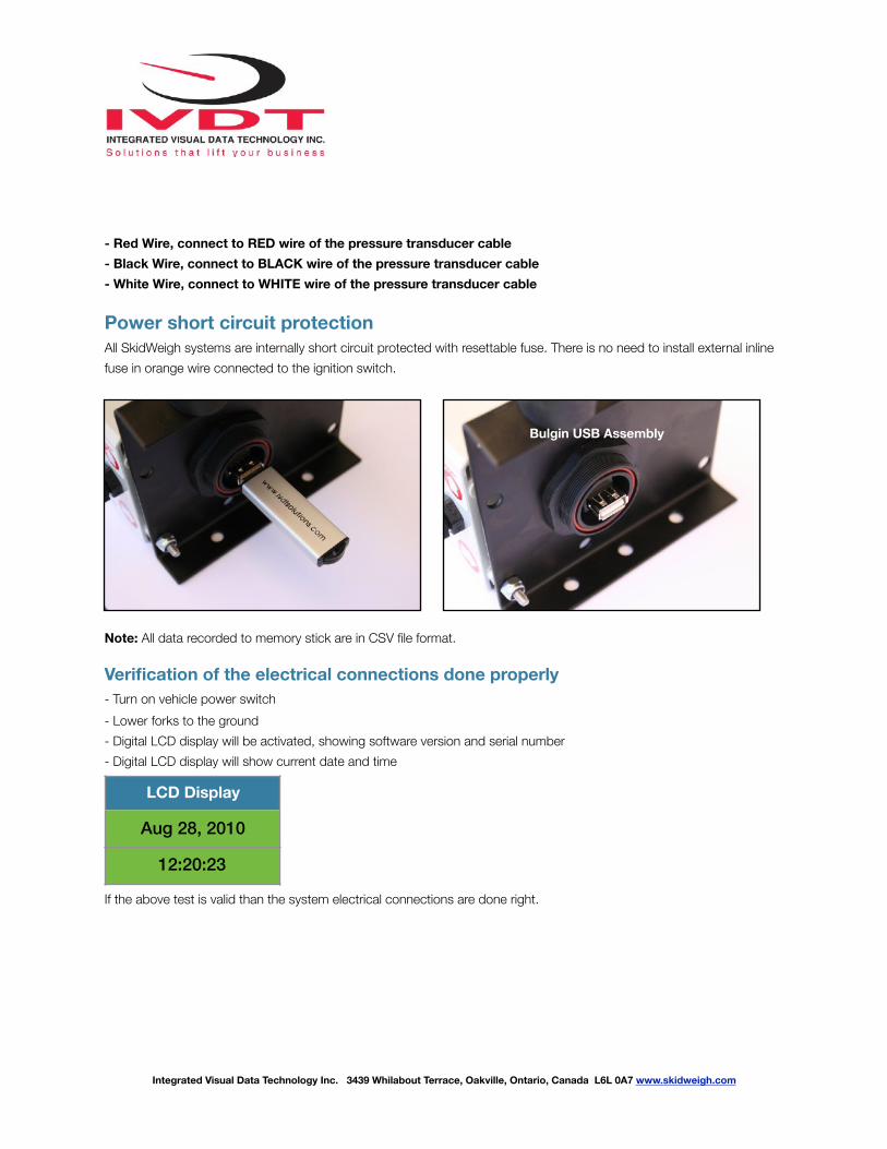
- Red Wire, connect to RED wire of the pressure transducer cable - Black Wire, connect to BLACK wire of the pressure transducer cable - White Wire, connect to WHITE wire of the pressure transducer cable
Power short circuit protection All SkidWeigh systems are internally short circuit protected with resettable fuse. There is no need to install external inline fuse in orange wire connected to the ignition switch.
Note: All data recorded to memory stick are in CSV file format.
Verification of the electrical connections done properly - Turn on vehicle power switch - Lower forks to the ground - Digital LCD display will be activated, showing software version and serial number - Digital LCD display will show current date and time
If the above test is valid than the system electrical connections are done right.
LCD Display
Aug 28, 2010
12:20:23
Integrated Visual Data Technology Inc. 3439 Whilabout Terrace, Oakville, Ontario, Canada L6L 0A7 www.skidweigh.com
Bulgin USB Assembly

!
Integrated Visual Data Technology Inc. 3439 Whilabout Terrace, Oakville, Ontario, Canada L6L 0A7 www.skidweigh.com
LCD Display Special Functions Button Bluetooth Icon
Keypad
“Enter key” ↵ Toggle Arrows Keys in set up menu
Print key
FUNCTION MODE KEY
F 9 ADMINISTRATIVE MENU (Password protected)
F 0 OPERATOR MENU (Bluetooth pairing, Tare input, Parts Count, etc. if applicable)
Impact Monitoring
Mounting Bracket With Anti Vibration Mounts
!
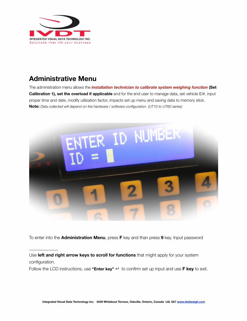
Administrative Menu The administration menu allows the installation technician to calibrate system weighing function (Set Calibration 1), set the overload if applicable and for the end user to manage data, set vehicle ID#, input proper time and date, modify utilization factor, impacts set up menu and saving data to memory stick. Note: Data collected will depend on the hardware / software configuration. (UT10 to UT60 series)
To enter into the Administration Menu, press F key and than press 9 key. Input password
_____________ Use left and right arrow keys to scroll for functions that might apply for your system configuration. Follow the LCD instructions, use “Enter key” ↵ to confirm set up input and use F key to exit.
Integrated Visual Data Technology Inc. 3439 Whilabout Terrace, Oakville, Ontario, Canada L6L 0A7 www.skidweigh.com
!
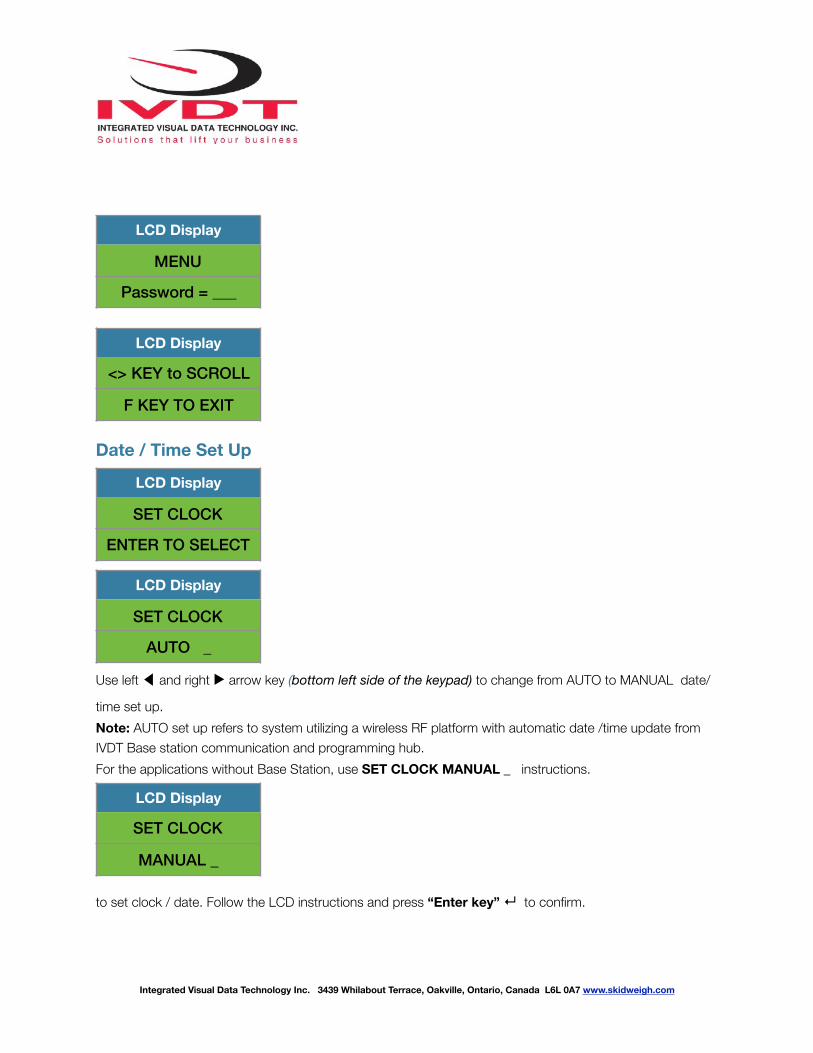
Date / Time Set Up
Use left ◀ and right ▶ arrow key (bottom left side of the keypad) to change from AUTO to MANUAL date/
time set up. Note: AUTO set up refers to system utilizing a wireless RF platform with automatic date /time update from IVDT Base station communication and programming hub. For the applications without Base Station, use SET CLOCK MANUAL _ instructions.
to set clock / date. Follow the LCD instructions and press “Enter key” ↵ to confirm.
LCD Display
MENU
Password = ___
LCD Display
<> KEY to SCROLL
F KEY TO EXIT
LCD Display
SET CLOCK
ENTER TO SELECT
LCD Display
SET CLOCK
AUTO _
LCD Display
SET CLOCK
MANUAL _
Integrated Visual Data Technology Inc. 3439 Whilabout Terrace, Oakville, Ontario, Canada L6L 0A7 www.skidweigh.com

!
Press “Enter key” ↵ to confirm the setting. The cursor will automatically move to the next item to be changed
( Month, Day, Year, Hours, Minutes, Seconds). On the last correction, seconds item press “Enter key” ↵ to confirm
new date / time set up.
Set vehicle ID# - Maximum input number for vehicle ID# is 3 digits.
LCD Display
Aug 28, 2010
12:20:23
LCD Display
<> KEY to SCROLL
F KEY TO EXIT
LCD Display
SET VEHICLE ID
ENTER TO SELECT
LCD Display
ENTER VEHICLE ID
1_
LCD Display
VEHICLE ID
CONFIGURATED
Integrated Visual Data Technology Inc. 3439 Whilabout Terrace, Oakville, Ontario, Canada L6L 0A7 www.skidweigh.com

!
Saving recorded data to USB memory stick
The ED3/ED4-AT SkidWeigh Plus system will allow you to download all recorded data onto a USB drive. Follow instructions shown on the LCD displayThis function is located in Administrative Menu.
When the system has finished uploading the data to the USB memory stick the LCD display will prompt you to erase the SDRAM , all files contained on the UTX SkidWeigh Plus. Make selection Y or N and press “Enter key” ↵ to confirm selection and the system will automatically bring you back to the main screen in the administrative menu.
LCD Display
<> KEY TO SCROLL
F KEY TO EXIT
LCD Display
SAVE TO USB
ENTER TO SELECT
LCD Display
SAVING TO USB
—————-
LCD Display
ERASE SDRAM ? N
LCD Display
<> KEY TO SCROLL
F KEY TO EXIT
Integrated Visual Data Technology Inc. 3439 Whilabout Terrace, Oakville, Ontario, Canada L6L 0A7 www.skidweigh.com
Print / Send “Enter key” ↵
!
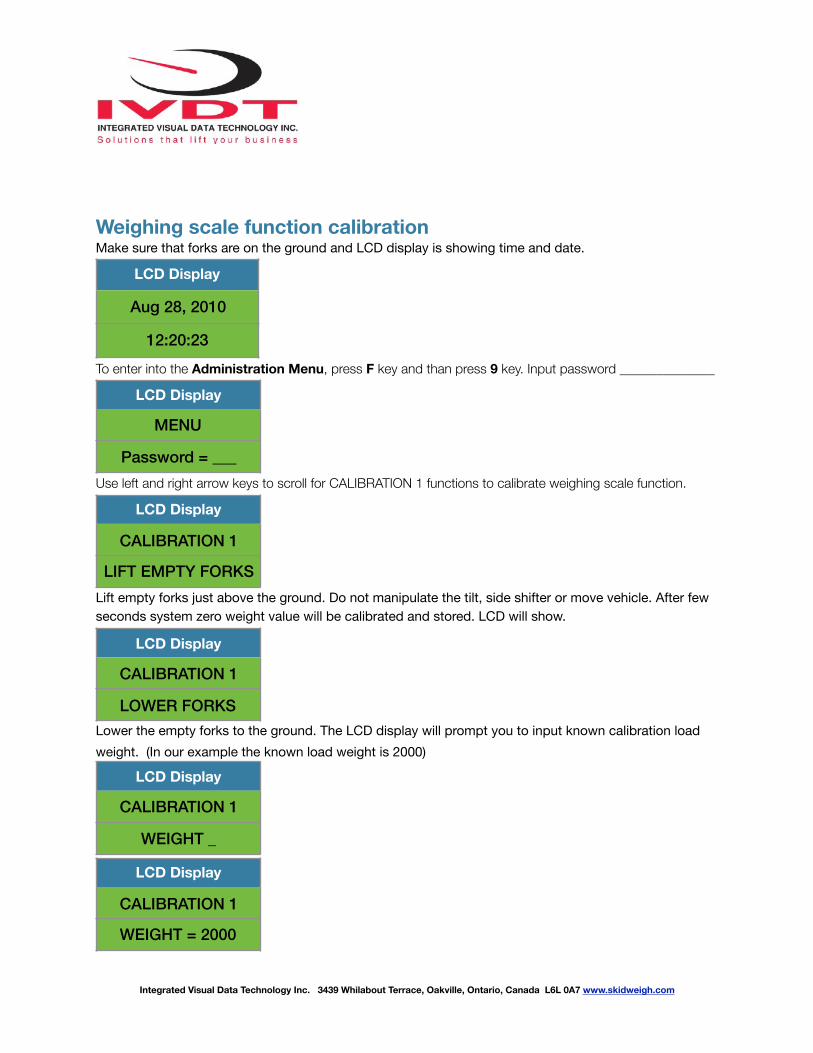
Weighing scale function calibration Make sure that forks are on the ground and LCD display is showing time and date.
To enter into the Administration Menu, press F key and than press 9 key. Input password _____________
Use left and right arrow keys to scroll for CALIBRATION 1 functions to calibrate weighing scale function.
Lift empty forks just above the ground. Do not manipulate the tilt, side shifter or move vehicle. After few seconds system zero weight value will be calibrated and stored. LCD will show.
Lower the empty forks to the ground. The LCD display will prompt you to input known calibration load weight. (In our example the known load weight is 2000)
LCD Display
Aug 28, 2010
12:20:23
LCD Display
MENU
Password = ___
LCD Display
CALIBRATION 1
LIFT EMPTY FORKS
LCD Display
CALIBRATION 1
LOWER FORKS
LCD Display
CALIBRATION 1
WEIGHT _
LCD Display
CALIBRATION 1
WEIGHT = 2000
Integrated Visual Data Technology Inc. 3439 Whilabout Terrace, Oakville, Ontario, Canada L6L 0A7 www.skidweigh.com

!
Pick up a known load weight and lower the loaded forks to the ground. Input into the system the known load weight (Our example is 2000) and press “Enter key” ↵ . The LCD display will show
Activate lift control valve and lift loaded forks just above the ground. Do not manipulate the tilt, side shifter or move vehicle. After few seconds calibrated load weight value of 2000 will stored. Within few seconds the LCD will show.
As soon the loaded forks are lowered to the ground the LCD display will show date / time . System check weighing function calibration is completed. System is ready to be used.
Overload Warning Function (Optional)
As soon forks are lowered the LCD display will show
The LCD display will prompt you to input the overload load weight value. Input the applicable overload value and press “Enter key” ↵ . Press F key to exit the ADMINISTRATIVE MENU.
LCD Display
CALIBRATION 1
LIFT LOAD
LCD Display
CALIBRATION 1
LOWER FORKS
LCD Display
CALIBRATION 1
CONFIGURATED
LCD Display
CALIBRATION 1
LOWER FORKS
LCD Display
CALIBRATION 1
OVERLOAD = _
Integrated Visual Data Technology Inc. 3439 Whilabout Terrace, Oakville, Ontario, Canada L6L 0A7 www.skidweigh.com
!
Default Factory Set Up - Low impact 6 G , visual and audio - Audio alarm set to 5 seconds - High Impact 12 G , visual and audio - Audio alarm set to 5 seconds - Optional audio alarm in continuous mode until reseted by supervisor - Utilization factor, default value set to 30 (End use programable) - Safety checklist start time 7:00 AM (End use programable) - Safety checklist time period 8 hours (End use programable, 8 or 12 hours) - IDLING, automatic unidentify true idling events within utilization factor
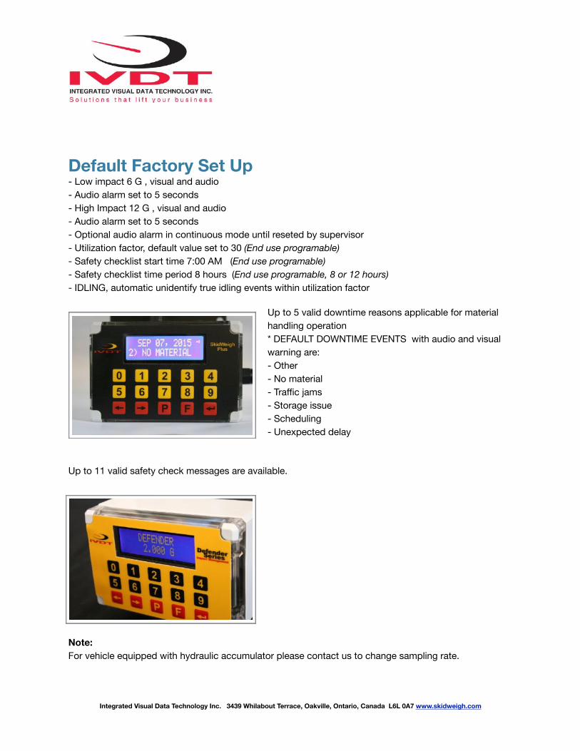
Up to 5 valid downtime reasons applicable for material handling operation * DEFAULT DOWNTIME EVENTS with audio and visual warning are: - Other - No material - Traffic jams - Storage issue - Scheduling - Unexpected delay
Up to 11 valid safety check messages are available.
Note: For vehicle equipped with hydraulic accumulator please contact us to change sampling rate.
Integrated Visual Data Technology Inc. 3439 Whilabout Terrace, Oakville, Ontario, Canada L6L 0A7 www.skidweigh.com

!
Lift Truck Operator Load Weighing Guide
Integrated Visual Data Technology Inc. 3439 Whilabout Terrace, Oakville, Ontario, Canada L6L 0A7 www.skidweigh.com
Loaded forks must be lowered to the ground LCD display must show date / time Lift the load approximately 2” off the ground. Do not use tilt, side shift or move vehicle during the weighing cycle Within few seconds LCD display will show the load weigh
* Impact detection, no operator input required * Overload detection, no operator input required * Safety checklist, operator input required
Vehicle Operational Idling Recordings Within Utilization Factor Visual /Audio notification of all idling events is shown to the operator on the LCD display
* Unidentify operational idling, no operator input required * Valid downtime reasons events, operator input required
Note: Use “P’ key to print and save load weight information to the USB. Use “Enter key” ↵ to accumulate individual load weight information.