SKIDDING WINCH MODELS FX65, FX90 AND FX120 - Wallenstein
52
SKIDDING WINCH MODELS FX65, FX90 AND FX120 OPERATOR'S MANUAL BY EMB MFG INC. EMB Manufacturing Inc. 4144 Boomer Line · St. Clements, On · N0B 2M0 · Canada Ph: (519) 699-9283 · Fax: (519) 699-4146 www.embmfg.com FX65 FX120 FX90 PRINTED IN CANADA REV 131011 PART NUMBER: Z97055
Transcript of SKIDDING WINCH MODELS FX65, FX90 AND FX120 - Wallenstein

SKIDDING WINCHMODELS FX65, FX90 AND FX120
OPERATOR'S MANUAL
BY EMB MFG INC.
EMB Manufacturing Inc.4144 Boomer Line · St. Clements, On · N0B 2M0 · Canada
Ph: (519) 699-9283 · Fax: (519) 699-4146 www.embmfg.com
FX65
FX120 FX90
PRINTED IN CANADAREV 131011 PART NUMBER: Z97055

2
TABLE OF CONTENTSDELIVERY INSPECTION REPORT ...................................................................4SERIAL NUMBER LOCATION ..........................................................................51 INTRODUCTION ...................................................................................62 SAFETY ................................................................................................7
2.1 GENERAL SAFETY .........................................................................82.2 EQUIPMENT SAFETY GUIDELINES ..............................................92.3 SAFETY TRAINING .......................................................................102.4 SAFETY SIGNS .............................................................................102.5 PREPARATION ..............................................................................112.6 MAINTENANCE SAFETY ..............................................................112.7 OPERATING SAFETY ...................................................................122.8 STORAGE SAFETY ......................................................................132.9 TRANSPORT SAFETY ..................................................................132.10 SIGN-OFF FORM ..........................................................................14
3 SAFETY SIGN LOCATIONS ..............................................................153.1 THREE PANEL SAFETY SIGNS ...................................................153.2 TWO PANEL SAFETY SIGNS .......................................................16
4 DRIVELINE DIMENSION ....................................................................175 OPERATION .......................................................................................18
5.1 TO THE NEW OPERATOR OR OWNER ......................................185.2 MACHINE COMPONENTS ...........................................................195.3 MACHINE BREAK-IN ....................................................................205.4 PRE-OPERATION CHECKLIST ....................................................205.5 CONTROLS ...................................................................................215.6 ATTACH AND DETACHING SKIDDER WINCH ............................225.7 FIELD OPERATION .......................................................................255.8 TRANSPORTING ..........................................................................405.9 STORAGE .....................................................................................415.9.1 PLACING IN STORAGE ................................................................415.9.2 REMOVING FROM STORAGE .....................................................41
6 SERVICE AND MAINTENANCE ........................................................426.1 SERVICE .......................................................................................426.1.1 FLUIDS AND LUBRICANTS ..........................................................426.1.2 GREASING ....................................................................................426.1.3 SERVICE ILLUSTRATION .............................................................436.1.4 SERVICE RECORD CHART .........................................................446.2 MAINTENANCE .............................................................................456.2.1 DRIVELINE MAINTENANCE .........................................................456.2.2 CLUTCH ADjUSTMENT ...............................................................466.2.3 ROLLER CHAIN TENSIONER ......................................................476.2.4 DRUM BRAKE ADjUSTMENT ......................................................48
7 TROUBLE SHOOTING .......................................................................488 SPECIFICATIONS ..............................................................................50
8.2 BOLT TORQUE .............................................................................51INDEX...............................................................................................................52

3
WARRANTYEffective on products retailed on or after January 1, 2011.
Register your product online at www.embmfg.com within 30 days of purchase to activate warranty.
This product is warranted to be free of defects in materials and workmanship under normal use and service, for a period of
from the date of purchase, when operated and maintained in accordance with the Operating and Maintenance Instructions supplied with this unit. Warranty is limited to the repair of the product and/or replacement of parts.
This warranty does not cover the following items:1) Machines or parts lost or damaged during shipment,2) Normal maintenance or adjustments after initial pre-service and set up is completed3) Normal replacement of service items.4) Accessory items / parts not supplied by EMB MFG INC.5) Damages resulting from:
• misuse, negligence, accident, theft or fire• use of improper or insufficient fuel, fluids or lubricants • use of parts or after market accessories other than genuine EMB MFG INC. parts • modifications, alteration, tampering or improper repair performed by parties other than an authorized dealer• any device or accessories installed by parties other than an authorized EMB dealer or distributor
Engines are covered by the manufacturer of the engine and covered by the warranty period specified by that manufacturer. Engine warranty must be registered at the engine manufactures website. For service contact your local engine dealer.
Under no circumstances will the manufacturer be liable for any consequential damage or expense of any kind, including loss of profits. The manufacturer is under no circumstances liable for tow vehicle of any kind. The manufacturer is not liable for the maintenance of the product.
This warranty is extended only to the original purchaser and is not transferable. Warranty is void if repairs are attempted by anyone other than a Wallenstein Authorized Service Centre.
If a difficulty develops with the product, contact the local dealer from which you purchased the unit. Only Wallenstein author-ized dealers are authorized to make repairs to the product or affect the replacement of defective parts, which will be done at no charge within a reasonable time after the receipt of the product. Unit or parts shall be returned at the customer’s expense to the Authorized Service Centre. Damage in transit is not covered by warranty. Include the original purchase receipt with any claim (keep a copy of the receipt for your files).
The distributor’s liability under warranty is limited to the repair of the product and/or replacement of parts and is given to the purchaser in lieu of all other remedies including incidental and consequential charges. There are no warranties, expressed or implied, other than those specified herein.
EMB MFG Inc4144 Boomer Line, St Clements, ON N0B 2M0 Canada
Phone: 519-699-9283 Fax: 519-699-4146 : attention to Warranty DeptEmail: [email protected]
WARRANTY IS VOID IF NOT REGISTERED
Three (3) Years for ConsumerOne (1) Year for Commercial/Rental
rev.201011

4
WALLENSTEINSKIDDING WINCH
DELIVERY INSPECTION REPORT
Date Dealer’s Rep. Signature
Date Owner's Signature
The above equipment and Operator’s Manual have been received by me and I have been thoroughly instructed as to care, adjustments, safe operation and applicable warranty policy.
This form must be filled out by the dealer and signed by both the dealer and the customer at the time of delivery.
Customer’s Name Dealer Name
Address Address
City, State/Province, Code City, State/Province, Code
Phone Number ( ) Phone Number ( )
Contact Name
Model
Serial Number Delivery Date
I have thoroughly instructed the buyer on the above described equipment which review included the Op-erator’s Manual content, equipment care, adjustments, safe operation and applicable warranty policy.
DEALER INSPECTION REPORT
SAFETY
____ All Decals Installed ____ Guards and Shields Installed and Secured ____ Review Operating and Safety Instructions
____ Check Condition of Cable ____ Fasteners Tight ____ Lubricate Machine ____ Retainers Installed Through Mounting Pins ____ PTO Driveline Telescopes and Shield Turns
To activate warranty, register your product online at
www.embmfg.com
5
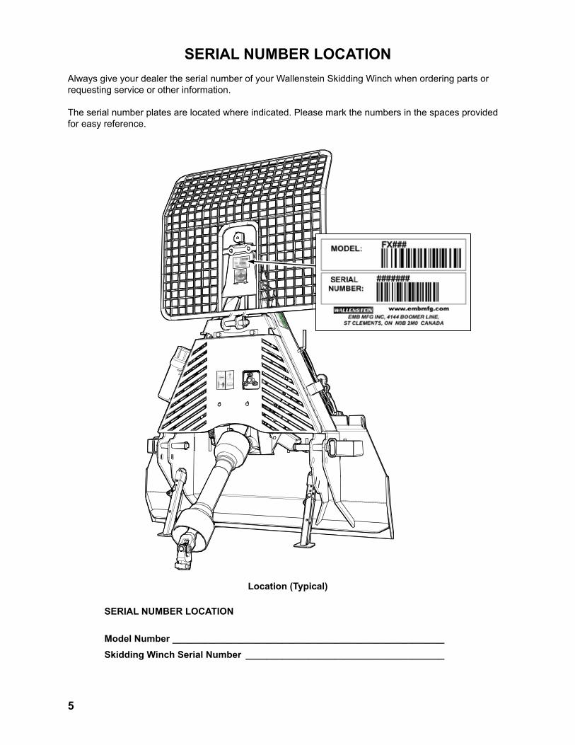
SERIAL NUMBER LOCATIONAlways give your dealer the serial number of your Wallenstein Skidding Winch when ordering parts or requesting service or other information.
The serial number plates are located where indicated. Please mark the numbers in the spaces provided for easy reference.
SERIAL NUMBER LOCATION
Model Number ____________________________________________________Skidding Winch Serial Number ______________________________________
Location (Typical)

6
1 INTRODUCTIONCongratulations on your choice of a Wallenstein Skidding Winch to compliment your operation. This equipment has been designed and manufactured to meet the needs of a discerning timber or landscaping industry.
Safe, efficient and trouble free operation of your Wallenstein Skidding Winch requires that you and any-one else who will be using or maintaining the Winch, read and understand the Safety, Operation, Mainte-nance and Trouble Shooting information contained within the Operator's Manual.
This manual covers the Wallenstein Skidding Winch Models FX65, FX90 and FX120. Use the Table of Contents or Index as a guide to locate required information.
Keep this manual handy for frequent reference and to pass on to new operators or owners. Call your Wallenstein dealer or the Distributor if you need assistance, information or additional copies of the manu-als.
OPERATOR ORIENTATION - The directions left, right, front and rear, as mentioned throughout this manual, are determined when sitting in the tractor driver's seat and facing over the winch.
FX65
FX90
FX120

7
2 SAFETYSAFETY ALERT SYMBOL
Why is SAFETY important to you?
The Safety Alert symbol identifies important safety messages on the Wallenstein Skidding Winch and in the manual. When you see this symbol, be alert to the possibility of personal injury or death. Follow the instructions in the safety message.
This Safety Alert symbol means ATTENTION! BECOME ALERT! YOUR SAFETY IS INVOLVED!
Accidents Disable and Kill Accidents Cost Accidents Can Be Avoided
3 Big Reasons
If you have any questions not answered in this manual or require additional copies or the manual is dam-aged, please contact your dealer or Wallenstein, 4144 Boomer Line, St. Clements, ON, N0B 2M0. Phone (519) 699-9283 or Fax (519) 699-4146.
DANGER - Indicates an imminently hazardous situation that, if not avoided, will result in death or serious injury. This signal word is to be limited to the most extreme situations typically for machine components which, for func-tional purposes, cannot be guarded.
WARNING - Indicates a potentially hazardous situation that, if not avoided, could result in death or serious injury, and includes hazards that are exposed when guards are removed. It may also be used to alert against unsafe practices.
CAUTION - Indicates a potentially hazardous situation that, if not avoided, may result in minor or moderate injury. It may also be used to alert against unsafe practices.
SIGNAL WORDS:
Note the use of the signal words DANGER, WARNING and CAUTION with the safety messages. The appropriate signal word for each message has been selected using thefollowing guide-lines:

8
SAFETYYOU are responsible for the SAFE operation and maintenance of your Wallenstein Skidding Winch. YOU must ensure that you and anyone else who is going to use, maintain or work around the Skidding Winch be familiar with the using and maintenance procedures and related SAFETY information contained in this manual. This manual will take you step-by-step through your working day and alerts you to all good safety practices that should be used while using the Skidding Winch.
Remember, YOU are the key to safety. Good safety practices not only protect you but also the people around you. Make these practices a work-ing part of your safety program. Be certain that EVERYONE using this equipment is familiar with the recommended using and maintenance proce-dures and follows all the safety precautions. Most accidents can be prevented. Do not risk injury or death by ignoring good safety practices.
• Skidding Winch owners must give operating instructions to operators or employees before allowing them to operate the machine, and at least annually thereafter.
• The most important safety device on this equipment is a SAFE operator. It is the op-erator’s responsibility to read and understand ALL Safety and Operating instructions in the manual and to follow these. Most accidents can be avoided.
• A person who has not read and understood all using and safety instructions is not qualified to use the machine. An untrained operator exposes himself and bystanders to possible serious injury or death.
• Do not modify the equipment in any way. Unauthorized modification may impair the function and/or safety and could affect the life of the equipment.
• Think SAFETY! Work SAFELY!
1. Read and understand the Op-erator’s Manual and all safety signs before using, maintain-ing, adjusting or cleaning the Skidding Winch.
2. Have a first-aid kit available for use should the need arise and know how to use it.
3. Have a fire extinguisher avail-able for use should the need arise and know how to use it.
4. Do not allow riders.
5. Wear appropriate protective gear. This list includes but is not limited to:
- A hard hat - Protective shoes with slip resistant soles - Protective glasses,
goggles or face shield - Heavy gloves - Wet weather gear - Hearing Protection - Respirator or filter mask
6. Install and secure all guards before starting.
7. Wear suitable ear protection for prolonged exposure to excessive noise.
8. Move controls to neutral or OFF position, stop engine, remove ignition key and place in your pocket, set park brake and wait for all moving parts to stop before servicing, repairing or maintaining.
9. Clear the area of people, especially small children, before using the unit.
10. Review safety related items annually with all personnel who will operating or maintaining the Skidding Winch.
2.1 GENERAL SAFETY

9
2.2 EQUIPMENT SAFETY GUIDELINES
1. Safety of the operator and bystanders is one of the main concerns in designing and de-veloping equipment. However, every year many accidents occur which could have been avoided by a few seconds of thought and a more careful approach to handling equipment. You, the operator, can avoid many accidents by observing the following precautions in this section. To avoid personal injury or death, study the following precautions and insist those working with you, or for you to follow them.
2. In order to provide a better view, certain photographs or illustrations in this manual may show an assembly with a safety shield removed. However, equipment should never be used in this condition. Keep all shields in place. If shield removal becomes necessary for repairs, replace the shield prior to use.
3. Replace any safety sign or instruction sign that is not readable or is missing. Location of such safety signs is indicated in this manual.
4. Never use alcoholic beverages or drugs which can hinder alertness or coordination while us-ing this equipment. Consult your doctor about using this machine while taking prescription medications.
5. Under no circumstances should young children be allowed to work with this equipment. Do not allow persons to use or assemble this unit until they have read this manual and have developed a thorough understanding of the safety precautions and of how it works. Review the safety instructions with all users annually.
6. This equipment is dangerous to children and persons unfamiliar with its operation. The operator should be a responsible, properly trained and physically able person familiar with machinery and trained in this equipment's operations. If the elderly are assisting with work, their physical limitations need to be recognized and accommodated.
7. Operate the machine only with a tractor equipped with an approved Roll-Over-Protective-Structure (ROPS). Always wear your seat belt when oper-ating the tractor. Serious injury or even death could result from falling off the tractor - - particularly during a turnover when the operator could be pinned under the ROPS or the tractor.
8. Never exceed the limits of a piece of machin-ery. If its ability to do a job, or to do so safely, is in question - DON'T TRY IT.
9. Do not modify the equipment in any way. Un-authorized modification may result in serious injury or death and may impair the function and life of the equipment.
10. In addition to the design and configuration of this implement, including Safety Signs and Safety Equipment, hazard control and ac-cident prevention are dependent upon the awareness, concern, prudence, and proper training of personnel involved in the operation, transport, maintenance, and storage of the machine. Refer also to Safety Messages and operation instruction in each of the appropri-ate sections of the tractor and machine manu-als. Pay close attention to the Safety Signs affixed to the tractor and the machine.

10
2.3 SAFETY TRAINING
1. Safety is a primary concern in the design and manufacture of our products. Unfortunately, our efforts to provide safe equipment can be wiped out by a single careless act of an operator or bystander.
2. In addition to the design and configuration of equipment, hazard control and accident pre-vention are dependent upon the awareness, concern, prudence and proper training of personnel involved in the operation, transport, maintenance and storage of this equipment.
3. It has been said, "The best safety feature is an informed, careful opera-tor." We ask you to be that kind of an operator. It is the operator's responsibility to read and under-stand ALL Safety and Using instructions in the manual and to follow these. Accidents can be avoided.
4. Working with unfamiliar equipment can lead to careless injuries. Read this manual before assembly or using, to acquaint yourself with the machine. If this machine is used by any person other than yourself, or is loaned or rented, it is the machine owner's responsibility to make certain that the operator, prior to using:
a. Reads and understands the operator's manuals.
b. Is instructed in safe and proper use.
5. Know your controls and how to stop tractor and machine quickly in an emergency. Read
this manual and the one provided with tractor.
6. Train all new personnel and review instruc-tions frequently with existing workers. Be certain only a properly trained and physically able person will use the machinery. A person who has not read and understood all using and safety instructions is not qualified to use the machine. An untrained operator exposes himself and bystanders to possible serious in-jury or death. If the elderly are assisting with the work, their physical limitations need to be recognized and accommodated.
2.4 SAFETY SIGNS
1. Keep safety signs clean and legible at all times.
2. Replace safety signs that are missing or have become illegible.
3. Replaced parts that displayed a safety sign should also display the current sign.
4. Safety signs displayed in Section 3 each have a part number in the lower right hand corner. Use this part number when ordering replace-ment parts.
5. Safety signs are available from your author-ized Distributor or Dealer Parts Department or the factory.
How to Install Safety Signs:
• Be sure that the installation area is clean and dry.
• Be sure temperature is above 50°F (10°C).
• Determine exact position before you remove the backing paper.
• Remove the smallest portion of the split back-ing paper.
• Align the sign over the specified area and carefully press the small portion with the ex-posed sticky backing in place.
• Slowly peel back the remaining paper and carefully smooth the remaining portion of the sign in place.
• Small air pockets can be pierced with a pin and smoothed out using the piece of sign backing paper.
11
2.5 PREPARATION
1. Never use the machine until you have read and completely understand this manual, the tractor Operator's Manual and each of the Safety Messages found on the safety signs on the tractor and machine.
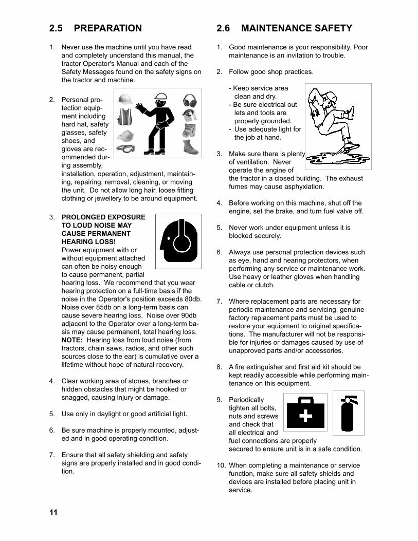
2. Personal pro-tection equip-ment including hard hat, safety glasses, safety shoes, and gloves are rec-ommended dur-ing assembly, installation, operation, adjustment, maintain-ing, repairing, removal, cleaning, or moving the unit. Do not allow long hair, loose fitting clothing or jewellery to be around equipment.
3. PROLONGED EXPOSURE TO LOUD NOISE MAY CAUSE PERMANENT HEARING LOSS!
Power equipment with or without equipment attached can often be noisy enough to cause permanent, partial hearing loss. We recommend that you wear hearing protection on a full-time basis if the noise in the Operator's position exceeds 80db. Noise over 85db on a long-term basis can cause severe hearing loss. Noise over 90db adjacent to the Operator over a long-term ba-sis may cause permanent, total hearing loss. NOTE: Hearing loss from loud noise (from tractors, chain saws, radios, and other such sources close to the ear) is cumulative over a lifetime without hope of natural recovery.
4. Clear working area of stones, branches or hidden obstacles that might be hooked or snagged, causing injury or damage.
5. Use only in daylight or good artificial light.
6. Be sure machine is properly mounted, adjust-ed and in good operating condition.
7. Ensure that all safety shielding and safety signs are properly installed and in good condi-tion.
2.6 MAINTENANCE SAFETY
1. Good maintenance is your responsibility. Poor maintenance is an invitation to trouble.
2. Follow good shop practices.
- Keep service area clean and dry.
- Be sure electrical out lets and tools are properly grounded.
- Use adequate light for the job at hand.
3. Make sure there is plenty of ventilation. Never operate the engine of the tractor in a closed building. The exhaust fumes may cause asphyxiation.
4. Before working on this machine, shut off the engine, set the brake, and turn fuel valve off.
5. Never work under equipment unless it is blocked securely.
6. Always use personal protection devices such as eye, hand and hearing protectors, when performing any service or maintenance work. Use heavy or leather gloves when handling cable or clutch.
7. Where replacement parts are necessary for periodic maintenance and servicing, genuine factory replacement parts must be used to restore your equipment to original specifica-tions. The manufacturer will not be responsi-ble for injuries or damages caused by use of unapproved parts and/or accessories.
8. A fire extinguisher and first aid kit should be kept readily accessible while performing main-tenance on this equipment.
9. Periodically tighten all bolts, nuts and screws and check that all electrical and fuel connections are properly secured to ensure unit is in a safe condition.
10. When completing a maintenance or service function, make sure all safety shields and devices are installed before placing unit in service.

12
2.7 OPERATING SAFETY1. Please remember it is important that you read
and heed the safety signs on the Skidding Winch. Clean or replace all safety signs if they cannot be clearly read and understood. They are there for your safety, as well as the safety of others. The safe use of this machine is strictly up to you, the operator.
2. All things with moving parts are potentially hazardous. There is no substitute for a cau-tious, safe-minded operator who recognizes potential hazards and follows reasonable safety practices. The manufacturer has designed this Skidding Winch to be used with all its safety equipment properly attached, to minimize the chance of accidents. Study this manual to make sure you have all safety equipment attached.
3. Close and secure all guards, deflectors and shields before starting and operating.
4. Read and understand operator's manual before starting. Review safety instructions annually.
5. Personal protection equipment including hear-ing protection, hard hat, safety glasses, safety shoes, and gloves are recommended during assembly, installation, operation, adjustment, maintaining, repairing, removal, or moving. Do not allow long hair, loose-fitting clothing, or jewellery to be around moving parts.
6. Do not allow anyone within 20 ft (6 m) of ma-chine or logs during operation. Keep children away.
7. Never place any part of your body where it would be in danger if movement should occur during assembly, installation, operation, main-tenance, repairing, unplugging or moving.
8. Move controls to neutral or OFF position, stop engine, remove ignition key and place in your pocket, set park brake and wait for all mov-ing parts to stop before servicing, repairing or maintaining.
9. Always lower frame blade to the ground when operating to provide stability.
10. Stand at least 10 ft (3 m) to the side of winch to pull control rope when operating winch.
11. Do not operate winch from tractor seat unless protective shield is in place.
12. Never stand directly in line with cable while pulling.
13. Check cable condition before using winch. Cable may break during operation if it is cor-roded, knotted, has broken strands or sharp kinks. Replace cable if damaged.
14. Do not touch cable during operation.
15. Never use alcoholic beverages or drugs which can hinder alertness or coordination while operating this equipment. Consult your doc-tor about operating this machine while taking prescription medications.
16. Do not allow riders on this machine at any time. There is no safe place for any riders.
17. Operate only on level ground and lower winch blade when winching.
18. Do not exceed winching angle of more than + 25°.
19. Always winch up a slope.
20. Do not winch across a slope.
21. Do not operate on hillsides or when working area is cluttered, wet, muddy or icy to prevent slipping and tripping.
22. Keep working area clean and free of debris to prevent tripping. Operate only on level ground.
23. Stop engine when leaving unattended.
24. Do not exceed a safe travel speed when transporting.
25. Do not use a tractor unless it is equipped with a ROPS.
26. Be sure the tractor is equipped with a full complement of suitcase weights on the front frame or a front end loader for added stability.

13
2.8 STORAGE SAFETY1. Store the unit in an area away from human
activity.
2. Do not children to play on or around the stored machine.
3. Store the unit in a dry, level area. Support the frame with planks if required.
2.9 TRANSPORT SAFETY
1. Comply with state and local laws governing safety and transporting of machinery on public roads.
2. Check that all the lights, reflectors and other lighting requirements are installed and in good working condition.
3. Do not exceed a safe travel speed. Slow down for rough terrain and cornering.
4. Be sure the winch is hitched positively to the tractor and retainers are used through the mounting pins.
5. Do not drink and drive.
6. Be a safe and courteous driver. Always yield to oncoming traffic in all situations, including narrow bridges, intersections, etc. Watch for traffic when operating near or crossing road-ways.
7. Never allow riders on the machine.

14
2.10 SIGN-OFF FORMWallenstein follows the general Safety Standards specified by the American Society of Agricultural and Biological Engineers (ASABE) and the Occupational Safety and Health Administration (OSHA). Anyone who will be using and/or maintaining the Skidding Winch must read and clearly understand ALL Safety, Usage and Maintenance information presented in this manual.
Do not use or allow anyone else to use this winch until such information has been reviewed. Annually re-view this information before the season start-up.
Make these periodic reviews of SAFETY and OPERATION a standard practice for all of your equipment. We feel that an untrained operator is unqualified to use this machine.
A sign-off sheet is provided for your record keeping to show that all personnel who will be working with the equipment have read and understand the information in the Operator’s Manual and have been instructed in the operation of the equipment.
DATE EMPLOYEES SIGNATURE EMPLOYERS SIGNATURESIGN-OFF FORM

15
REMEMBER - If safety signs have been damaged, removed, become illegible or parts replaced without safety signs, new signs must be applied. New safety signs are available from your authorized dealer.
3 SAFETY SIGN LOCATIONS3.1 THREE PANEL SAFETY SIGNSThe types of safety signs and locations on the equipment are shown in the illustrations that follow. Good safety requires that you familiarize yourself with the various safety signs, the type of warning and the area, or particular function related to that area, that requires your SAFETY AWARENESS.
• Think SAFETY! Work SAFELY!
A
Z94041
FLYING OBJECT HAZARDSTAY BEHIND SCREEN
To prevent serious injury or death from a flying object:
• Stay behind protective screen while operating winch when seated on tractor.
• Stay at least 10 ft. (3m) away from frame when operating from the side.
• Release tension on cable before unhooking log.
WARNING
Z94043
Z94043
Z94042
Z94042
16
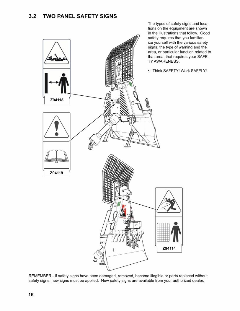
REMEMBER - If safety signs have been damaged, removed, become illegible or parts replaced without safety signs, new signs must be applied. New safety signs are available from your authorized dealer.
Z94118
Z94119
Z94114
3.2 TWO PANEL SAFETY SIGNSThe types of safety signs and loca-tions on the equipment are shown in the illustrations that follow. Good safety requires that you familiar-ize yourself with the various safety signs, the type of warning and the area, or particular function related to that area, that requires your SAFE-TY AWARENESS.
• Think SAFETY! Work SAFELY!

17
Fig. 5 DRIVELINE DIMENSIONS
Fig. 6 CUT OFF DIMENSION
Fig. 7 SHORTENING
4 DRIVELINE DIMENSIONA PTO driveline is supplied with the machine. To accommodate the variety of 3 point hitch geom-etry available today, the driveline may be too long for your machine. It is very important that the driveline be free to telescope and not bottom out when going through its working range. If the driveline bottoms out, the bearings on both the machine and tractor PTO shaft will be overloaded and will fail in a short time.
1. To determine the proper length of the driveline, follow this procedure:
a. Clear the area of bystanders, especially small children.
b. Attach the winch to the tractor (see sec-tion 5.8) but do not attach the driveline.
c. Raise the machine until the input shaft is level with the tractor PTO shaft.
d. Measure the dimension between the lock-ing grooves on the tractor PTO shaft and the machine input shaft.
e. Measure the same dimensions on the compressed driveline.
f. If the compressed driveline dimension exceeds the machine dimension, the driveline will have to be cut.
2. When cutting the driveline, follow this pro-cedure:
a. Subtract the machine dimension "A" from the uncut driveline dimension "B", see fig 5. This dimension determines how much the shaft needs to be shortened.
b. To be sure the shaft doesn't bottom out, add one inch (25 mm) to the cut off di-mension to determine (C) the final cut off dimension.
c. Use a hacksaw to cut dimension (C) from both ends. Cut both the plastic tubes and the metal cores.
d. Use a file to remove the burrs from the edges that were cut.
e. Assemble the 2 ends of the shaft.
f. Make sure the shaft can telescope freely. If it does not, separate the 2 parts and inspect for burrs or cuttings on the shaft ends. Be sure it telescopes freely before installing.

18
5 OPERATION
The Wallenstein Skidding Wenches are designed to connect to and pull logs to the machine. The operator should be familiar with the machine prior to starting.
It is the responsibility of the owner or opera-tor to read this manual and to train all other operators before they start working with the machine. Follow all safety instructions exact-ly. Safety is everyone's business. By follow-ing recommended procedures, a safe working environment is provided for the operator, bystanders and the area around the worksite. Untrained operators are not qualified to use the machine.
Follow all safety instructions exactly. Safety is everyone's business. By following recom-mended procedures, a safe working environ-ment is provided for the operator, bystanders and the area around the worksite. Untrained operators are not qualified to operate the ma-chine.
Many features incorporated into this machine are the result of suggestions made by customers like you. Read this manual carefully to learn how to use the winch safely and how to set it to provide maximum field efficiency. By following the using instructions in conjunction with a good mainte-nance program, your Skidding Winch will provide many years of trouble-free service.
5.1 TO THE NEW OPERATOR OR OWNER
OPERATING SAFETY• Read and understand operator's manual
before starting. Review safety instructions annually.
• Do not allow anyone within 20 ft (6 m) of machine or logs during operation. Keep chil-dren away.
• Move controls to neutral or OFF position, stop engine, remove ignition key and place in your pocket, set park brake and wait for all moving parts to stop before servicing, repairing or maintaining.
• Always lower frame blade to the ground when operating to provide stability.
• Stand at least 10 ft (3 m) to the side of winch to pull control rope when operating winch.
• Do not operate winch from tractor seat unless protective shield is in place.
• Never stand directly in line with cable while pulling.
• Check cable condition before using winch. Cable may break during operation if it is corroded, knotted, has broken strands or sharp kinks. Replace cable if damaged.
• Do not touch cable during operation.
• Do not allow riders on this machine at any time. There is no safe place for any riders.
• Operate only on level ground and lower winch blade when winching.
• Do not exceed winching angle of more than + 25°.
• Always winch up a slope.
• Do not winch across a slope.
• Do not operate on hillsides or when working area is cluttered, wet, muddy or icy to prevent slipping and tripping.
• Keep working area clean and free of debris to prevent tripping. Operate only on level ground.
• Do not use a tractor unless it is equipped with a ROPS.
• Be sure the tractor is equipped with a full complement of suitcase weights on the front frame or a front end loader for added stability.

19
5.2 MACHINE COMPONENTS
Fig. 8 PRINCIPLE COMPONENTS
Top Cable Pulley
PTO Driveline
Manual Tube
Chain Tow Bar
Snatch Block
Safety Screen
Drum Lock Rope (green)
Winch Clutch Rope (white)
Support Legs
Anchor Blade
Winch Cable
Draw Bar
Clutch Adjuster
Chain Key Hole Slider
The Wallenstein Skidding Winch consists of a winch mounted in a frame to pull or winch logs. The white rope which exits out of the top of the frame through a swivel pulley, engages the winch clutch to pull in the cable. The en-gaging clutch and rope is spring-loaded and will return to its free-wheeling mode when the rope is released. The green rope, which exits the frame on the left, locks the winch drum which allows the machine to be used as a skidding unit.
Power to drive the winch is provided through the tractor PTO and a drive-line. A blade on the bottom back of the frame is used to anchor the ma-chine when winching. The skidding winch is lowered so the blade digs itself into the ground as the weight of the
The cable is routed out through the top of the frame and goes through a pulley and snatchblock. Keyhole sliders on the cable are used to attach additional logs when pulling. A towing bar is designed into the rear frame to attach more logs when skidding. A safety screen is mounted on the top of the frame for optimal protection.

20
5.3 MACHINE BREAK-INAlthough there are no operational restrictions on the Skidding Winch when used for the first time, it is recommended that the following mechanical items be checked:
A. After operating for 1 hour:
1. Torque all fasteners and hardware.
2. Check condition of rotor winch clutch.
3. Check the condition of the cable. Replace if kinked, frayed or if it has any broken strands.
4. Check for entangled material. Remove all entangled material before resuming work.
5. Lubricate all grease fittings.
B. After operating for 10 hours:
1. Repeat steps 1 through 5 listed above. (Section A)
2. Go to the normal servicing and mainte-nance schedule as defined in the Mainte-nance Section.
5.4 PRE-OPERATION CHECKLIST
Efficient and safe operation of the Wallenstein Skidding Winch requires that each operator reads and understands the using procedures and all re-lated safety precautions outlined in this section. A pre-operation checklist is provided for the opera-tor. It is important for both the personal safety and maintaining good mechanical condition that this checklist is followed.
Before operating the Winch and each time there-after, the following areas should be checked off:
1. Lubricate the machine per the schedule out-line in the Maintenance Section.
2. Check for entangled material. Remove any twine, wire or other material that has become entangled.
3. Check the condition of the cable. Replace if kinked, frayed or if it has any broken strands
4. Check that all bearings turn freely. Replace any that are rough or seized.
5. Make sure that all guards and shields are in place, secured and functioning as designed.
6. Check the condition of the winch clutch. It must be in good condition to operate properly.

21
5.5 CONTROLS
Before starting to work, all operators should famil-iarize themselves with the location and function of the controls.
1. Engage Winch Clutch: This spring-loaded clutch, actuated by the
white rope, engages or releases the cable retracting winch. Pull firmly on the white rope and hold to engage the clutch and retract the cable. If the cable does not retract, pull harder on the rope to increase the engaging force for heavier loads.
The white clutch rope runs through a swivel pulley which allows it to be operated from any angle behind the skidding winch.
2. Disengage Winch Clutch Release the rope to disengage the clutch and
winch will go into its free-wheeling status.
3. Engage Winch Lockout: Pull on the green winch lock rope to engage
the drum lock. Pull sharply on the rope to engage the latching lock brake on the winch drum when preparing to drive the tractor ahead.
When the brake lock is engaged, the winch drum is locked and the machine to tow or pull a load.
4. Disengage Winch Lockout: Pull on the white winch clutch rope disen-
gage the drum lock. The winch will then free wheel and the cable is ready to be retracted or pulled out by hand.
On the CE version of the Skidding Winch, the operator has the option to automatically engage the drum lock after winching: apply tension to the green brake rope to engage the brake, tie a loop in the rope and hook the loop around the CE brake hook on the winch frame.
Clutch
Brake
Fig. 9 CONTROLS
NOTEDo not allow clutch to
slip, engage clutch fully to avoid premature wear and excessive heat in the
clutch ass'y.
Brake Hook (CE Version)
White rope (winch clutch)
Green rope (winch lock)

22
5.6 ATTACH AND DETACHING SKIDDER WINCHWhen attaching winch to a tractor, follow this procedure:
1. Clear the area of bystanders, especially small children.
2. Make sure there is enough room and clear-ance to safely back up to the winch.
3. Place the tractor arms in their full sway position.
4. Back up slowly and align the lower link arms to the pins on the machine.
5. Attaching to 3-Point Hitch
Fig. 10 TRACTOR LOWER LINKS
Aligned
Pinned
Fig. 11 LOWER ARMS
a. Align the left lower link with the left winch pin.
b. Insert the left pin through the ball and install the retainer.
c. Align the right arm to the pin by turning the jackscrew on the arm.
d. Insert the right pin through the ball and install the retainer. Return the jack-screw to its starting position.
IMPORTANTIt may be necessary to add weight to the lower lift arms to bring them to the required height.

23
6. Set the 3 point hitch in the non-sway position (see tractor manual for details).
7. PTO install driveline:
a. Depress the pin on the yoke, align the splines and slide the yoke onto the trac-tor shaft.
b. Release the pin and make sure the locking pin clicks into position.
c. Attach the shield anchor chain to an adjacent frame member.
NOTEBe sure the telescoping
portion of the shaft is greased and free of dirt.
IMPORTANTBefore proceeding,
ensure the driveline has been cut to the required
length, see page 17.
Fig. 13 PTO SHAFT
e. Remove the top pin and install the top link. Use the turnbuckle to align the top link. Insert the pins and install the retainers. Return the turnbuckle to its original length and lock.
Shaft
Anchor Chain
Fig. 12 TOP LINK

24
8. Slowly raise the machine through its working range to make sure the telescoping portion of the PTO shaft doesn't bottom out.
9. Level the machine front and rear, and side to side using the jackscrew on the right arm and the turnbuckle on the top link.
The winch should always be level on the ground in its working position.
11. Raise support legs and lock with snapper pins.
12. To detach skidder from the tractor, reverse the above procedure. Always park the machine in a dry, level area. Ensure support legs are lowered and locked in position.
If vandalism is a problem, remove the PTO driveline and store in a secure place. Place planks under the frame or support legs if required.
Fig. 14 LEVELLING ADJUSTMENTS
Fig. 15 SUPPORT LEGS RAISED
25
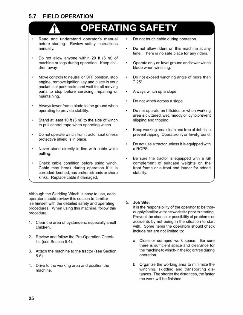
5.7 FIELD OPERATION
Although the Skidding Winch is easy to use, each operator should review this section to familiar-ize himself with the detailed safety and operating procedures. When using this machine, follow this procedure:
1. Clear the area of bystanders, especially small children.
2. Review and follow the Pre-Operation Check-list (see Section 5.4).
3. Attach the machine to the tractor (see Section 5.6).
4. Drive to the working area and position the machine.
OPERATING SAFETY• Read and understand operator's manual
before starting. Review safety instructions annually.
• Do not allow anyone within 20 ft (6 m) of machine or logs during operation. Keep chil-dren away.
• Move controls to neutral or OFF position, stop engine, remove ignition key and place in your pocket, set park brake and wait for all moving parts to stop before servicing, repairing or maintaining.
• Always lower frame blade to the ground when operating to provide stability.
• Stand at least 10 ft (3 m) to the side of winch to pull control rope when operating winch.
• Do not operate winch from tractor seat unless protective shield is in place.
• Never stand directly in line with cable while pulling.
• Check cable condition before using winch. Cable may break during operation if it is corroded, knotted, has broken strands or sharp kinks. Replace cable if damaged.
• Do not touch cable during operation.
• Do not allow riders on this machine at any time. There is no safe place for any riders.
• Operate only on level ground and lower winch blade when winching.
• Do not exceed winching angle of more than + 25°.
• Always winch up a slope.
• Do not winch across a slope.
• Do not operate on hillsides or when working area is cluttered, wet, muddy or icy to prevent slipping and tripping.
• Keep working area clean and free of debris to prevent tripping. Operate only on level ground.
• Do not use a tractor unless it is equipped with a ROPS.
• Be sure the tractor is equipped with a full complement of suitcase weights on the front frame or a front end loader for added stability.
5. Job Site: It is the responsibility of the operator to be thor-
oughly familiar with the work site prior to starting. Prevent the chance or possibility of problems or accidents by not being in the situation to start with. Some items the operators should check include but are not limited to:
a. Close or cramped work space. Be sure there is sufficient space and clearance for the machine to winch-in the log or tree during operation.
b. Organize the working area to minimize the winching, skidding and transporting dis-tances. The shorter the distances, the faster the work will be finished.

26
Fig. 16 TRAINING
6. Training: Each operator must be trained in the
proper operating procedures prior to being allowed to operate the machine.
a. Review control location, function and movement directions.
b. Move the unit to a large open area to allow the operator to become familiar with control function and machine response.
c. When a new operator is familiar and comfortable with the machine, they can proceed with the work. Do not allow untrained operators to use the machine. They can endanger themselves and others or damage property and the ma-chine.
27
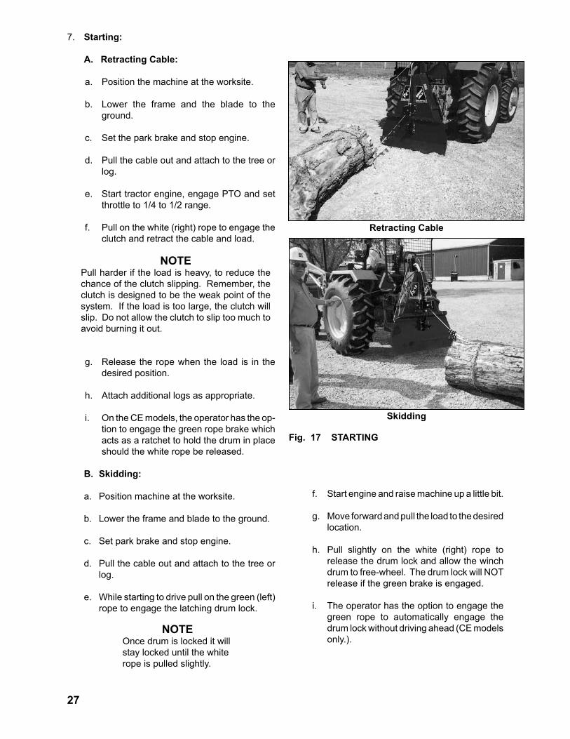
7. Starting:
A. Retracting Cable:
a. Position the machine at the worksite.
b. Lower the frame and the blade to the ground.
c. Set the park brake and stop engine.
d. Pull the cable out and attach to the tree or log.
e. Start tractor engine, engage PTO and set throttle to 1/4 to 1/2 range.
f. Pull on the white (right) rope to engage the clutch and retract the cable and load.
g. Release the rope when the load is in the desired position.
h. Attach additional logs as appropriate.
i. On the CE models, the operator has the op-tion to engage the green rope brake which acts as a ratchet to hold the drum in place should the white rope be released.
B. Skidding:
a. Position machine at the worksite.
b. Lower the frame and blade to the ground.
c. Set park brake and stop engine.
d. Pull the cable out and attach to the tree or log.
e. While starting to drive pull on the green (left) rope to engage the latching drum lock.
NOTEPull harder if the load is heavy, to reduce the chance of the clutch slipping. Remember, the clutch is designed to be the weak point of the system. If the load is too large, the clutch will slip. Do not allow the clutch to slip too much to avoid burning it out.
Fig. 17 STARTING
Retracting Cable
Skidding
NOTEOnce drum is locked it will stay locked until the white rope is pulled slightly.
f. Start engine and raise machine up a little bit.
g. Move forward and pull the load to the desired location.
h. Pull slightly on the white (right) rope to release the drum lock and allow the winch drum to free-wheel. The drum lock will NOT release if the green brake is engaged.
i. The operator has the option to engage the green rope to automatically engage the drum lock without driving ahead (CE models only.).

28
8. Stopping:
A. Retracting Cable:
a. Release the white rope and the cable will stop retracting and go into the free-wheeling mode unless the green rope lock is engaged.
b. Turn PTO off and stop engine.
B. Skidding:
a. Stop the forward motion of the tractor.
b. Stop engine.
9. Emergency Stopping:
A. Retracting Cable:
a. Release cable, disengage PTO and stop engine.
B. Skidding:
a. Stop the forward motion of the tractor and stop engine.
10. Cable Condition: Always inspect the cable as it is pulled out of the
machine. Do not use the machine if the cable is kinked, frayed or any strand is broken. Any problem can result in early failure and create an unsafe operating condition. Replace damaged cable before resuming work.
Retracting Cable
Fig. 18 STOPPING
Skidding
Fig. 19 CABLE CONDITION

29
11. Operator Position: To avoid potential hazards while pulling a load,
the operator should be at least 10 ft (3 m) to the side of the machine while operating the winch.
When driving the tractor to skid a load, the op-
erator should set the winch drum lock and stay behind the safety screen.
Fig. 20 OPERATOR POSITION
Skidding
Pulling
Schematic - Pull
Schematic - Skid

30
Angle
Pull Angle Schematic
Fig. 21 PULL ANGLE
Fig. 22 PULLING
12. Pull Angle: It is recommended that the pull angle of the ca-
ble not exceed + 25° from the longitudinal axis of the tractor. Exceeding that angle can subject the tractor to a tipping load and tip the machine over.
Always move the tractor to reduce or eliminate the tipping load.
The cable can also be threaded through the snatchblock in its lowest position to lower the loading point and reduce the chance of tipping the tractor.
13. Tractor Position:
a. Pulling: Always pull the load directly behind the
tractor to minimize the chance of tipping or moving the tractor.
b. Operating: It is recommended that the tractor be posi-
tioned on the uphill side of the log or load to prevent the log from rolling down into the frame or operator. Being uphill allows the operator to see all aspects of the operation, and change/adjust the operation as re-quired.
31
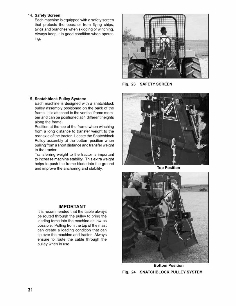
14. Safety Screen: Each machine is equipped with a safety screen
that protects the operator from flying chips, twigs and branches when skidding or winching. Always keep it in good condition when operat-ing.
15. Snatchblock Pulley System: Each machine is designed with a snatchblock
pulley assembly positioned on the back of the frame. It is attached to the vertical frame mem-ber and can be positioned at 4 different heights along the frame.
Position at the top of the frame when winching from a long distance to transfer weight to the rear axle of the tractor. Locate the Snatchblock Pulley assembly at the bottom position when pulling from a short distance and transfer weight to the tractor.
Transferring weight to the tractor is important to increase machine stability. This extra weight helps to push the frame blade into the ground and improve the anchoring and stability. Top Position
Fig. 23 SAFETY SCREEN
Bottom PositionFig. 24 SNATCHBLOCK PULLEY SYSTEM
IMPORTANTIt is recommended that the cable always be routed through the pulley to bring the loading force into the machine as low as possible. Pulling from the top of the mast can create a loading condition that can tip over the machine and tractor. Always ensure to route the cable through the pulley when in use

32
16. Log Chain: The operator must find a way to connect the
cable to the log or tree. A standard log chain works well and is readily available at most work sites. To use a log chain, follow this procedure:
a. Slide the log chain under the log and con-nect on the other side.
b. Extend the cable to the log chain.
c. Connect the hook on the end of the cable to the end of the log chain.
d. Start tractor, start PTO and engage winch clutch.
e. If skidding, drive forward.
Chain
Attached
Fig. 25 LOG CHAIN

33
Under Log
Winching
Cable End
Chain Hook
Ends
Fig. 26 CHOKER CHAIN
17. Optional Choker Chain: An optional choker chain is available to go
around logs and attach to the cable. Follow this procedure when using the choker chain:
a. Pull the cable out of the winch.
b. Push the end of the choker chain under the log.
c. Pull the ends together.
d. Slide the hook on the end over the chain and pull tight.
e. Connect the hook on the end of the cable over the choker chain.
f. Start tractor, start PTO and engage winch clutch.
g. If skidding, drive forward.
NOTEEnsure cable is routed
through the snatchblock pulley.
IMPORTANTDo not roll the log over the chain if working on slopes to reduce the chance of the log rolling away.

34
Sliders
Choker Chain
AttachedFig. 27 KEYHOLE SLIDERS
18. Keyhole Sliders: Each cable is equipped with 3 keyhole sliders to
allow additional logs to be attached to the cable. Follow this procedure when using the keyhole sliders:
a. Pull the choker chain around the log and secure.
b. Slide end of the choker chain through the keyhole slider.
c. Secure link in slot.
d. Start tractor, start PTO and engage winch clutch.
e. If skidding, drive forward.
35
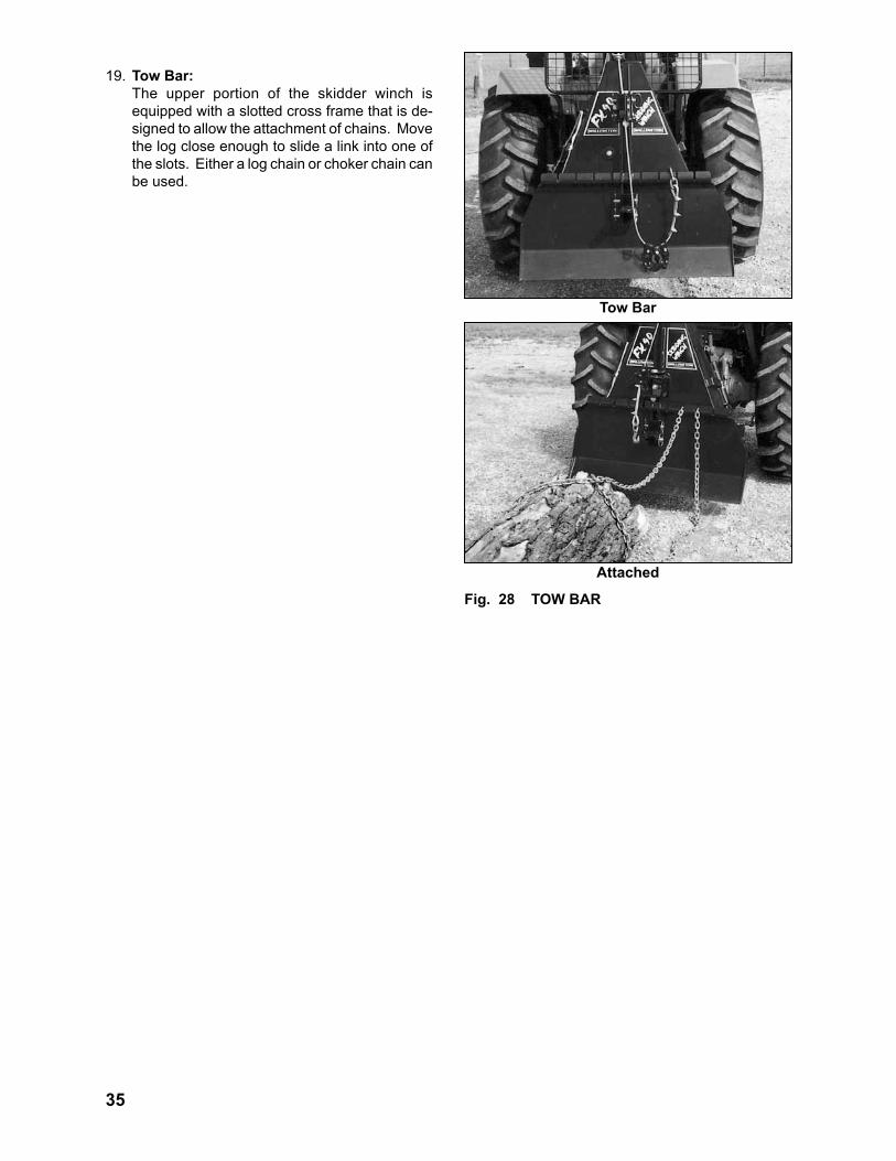
19. Tow Bar: The upper portion of the skidder winch is
equipped with a slotted cross frame that is de-signed to allow the attachment of chains. Move the log close enough to slide a link into one of the slots. Either a log chain or choker chain can be used.
Tow Bar
Fig. 28 TOW BAR
Attached
36
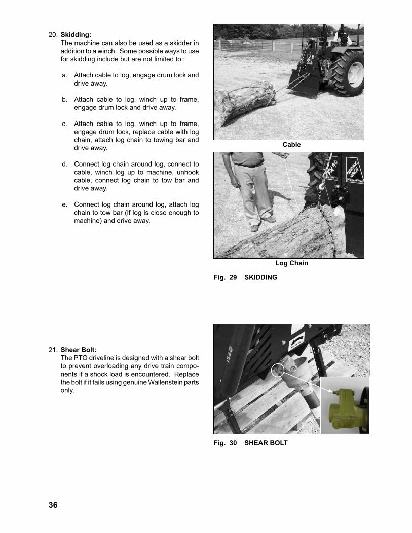
20. Skidding: The machine can also be used as a skidder in
addition to a winch. Some possible ways to use for skidding include but are not limited to::
a. Attach cable to log, engage drum lock and drive away.
b. Attach cable to log, winch up to frame, engage drum lock and drive away.
c. Attach cable to log, winch up to frame, engage drum lock, replace cable with log chain, attach log chain to towing bar and drive away.
d. Connect log chain around log, connect to cable, winch log up to machine, unhook cable, connect log chain to tow bar and drive away.
e. Connect log chain around log, attach log chain to tow bar (if log is close enough to machine) and drive away.
21. Shear Bolt: The PTO driveline is designed with a shear bolt
to prevent overloading any drive train compo-nents if a shock load is encountered. Replace the bolt if it fails using genuine Wallenstein parts only.
Cable
Log Chain
Fig. 29 SKIDDING
Fig. 30 SHEAR BOLT

37
Fig. 31 DRIVELINE ANGLE
22. Engine RPM: The Winch is designed to operate at up to 540
PTO RPM. However, when the winch is being used, the frame should be lowered to the ground with the blade biting into the ground to help an-chor the machine. In this operating condition, the driveline will be at a severe angle and it is recommended that the tractor only be run at a slow speed or at less than 1/4 throttle.
23. Driveline Angle: The driveline mounts between the tractor and
the winch. It is recommended that the angles of the universal joints be kept as straight as possible when operating to obtain the expected life. Operate only at low speed to reduce the loading on the bearings of the universals.
24. Tractor Weights: It is recommended that the tractor be equipped
with a full complement of suitcase weights on the front or a loader to provide the required bal-last for stability. This will reduce the chance of the tractor tipping back or to the side.
25. Tractor Brakes: The tractor parking brakes should always be
set whenever the machine is being used or the operator is leaving the seat. On steep slopes it is also recommended that chocks be placed behind all the tires to prevent the tractor from moving.

38
26. Rough Terrain: When moving the logs over rough terrain, drop
the load and drive across the rough condition. Re-attach the logs/load and winch the load across the rough conditions. Re-attach the load and drive away.
27. Operating Hints:
a. Always stay 10 ft (3 m) to the side of the of machine when operating the clutch rope and behind the safety screen when operat-ing from the tractor seat.
b. Lower frame to the ground to allow the blade to engage the ground when operating the winch.
c. Raise frame above the ground to clear the ground when skidding.
Fig. 32 OPERATING
Fig. 33 FIELD
Rope
Seat
Winching
Skidding

39
d. Use a log chain or optional choker chain to connect to the winch cable. Do not use a rope or other fabric attaching device to prevent breakage from abrasion or snag-ging.
e. Be sure the tractor is equipped with suit-case weights or a loader to increase stabil-ity.
f. Keep the driveline angles as small as pos-sible when using the winch.
Fig. 34 ATTACHING
Log Chain
Choker Chain
Fig. 35 DRIVELINE
40
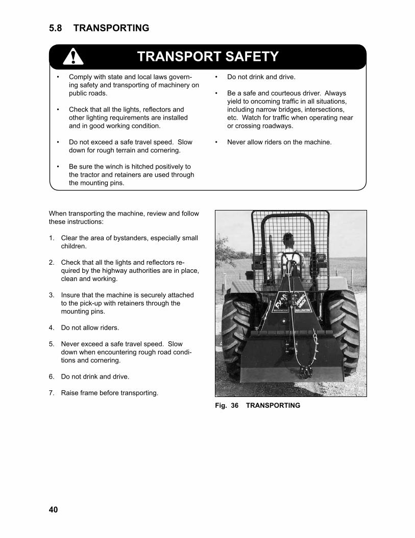
TRANSPORT SAFETY• Comply with state and local laws govern-
ing safety and transporting of machinery on public roads.
• Check that all the lights, reflectors and other lighting requirements are installed and in good working condition.
• Do not exceed a safe travel speed. Slow down for rough terrain and cornering.
• Be sure the winch is hitched positively to the tractor and retainers are used through the mounting pins.
• Do not drink and drive.
• Be a safe and courteous driver. Always yield to oncoming traffic in all situations, including narrow bridges, intersections, etc. Watch for traffic when operating near or crossing roadways.
• Never allow riders on the machine.
Fig. 36 TRANSPORTING
When transporting the machine, review and follow these instructions:
1. Clear the area of bystanders, especially small children.
2. Check that all the lights and reflectors re-quired by the highway authorities are in place, clean and working.
3. Insure that the machine is securely attached to the pick-up with retainers through the mounting pins.
4. Do not allow riders.
5. Never exceed a safe travel speed. Slow down when encountering rough road condi-tions and cornering.
6. Do not drink and drive.
7. Raise frame before transporting.
5.8 TRANSPORTING
41
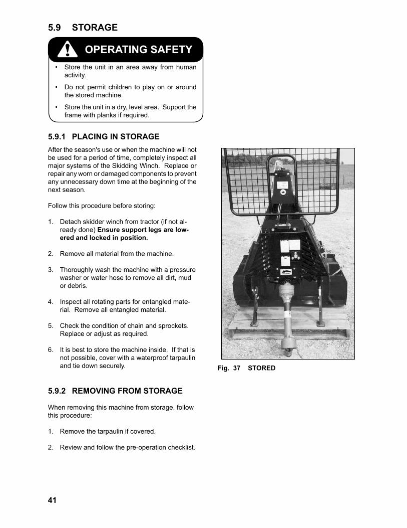
OPERATING SAFETY• Store the unit in an area away from human
activity.
• Do not permit children to play on or around the stored machine.
• Store the unit in a dry, level area. Support the frame with planks if required.
5.9 STORAGE
After the season's use or when the machine will not be used for a period of time, completely inspect all major systems of the Skidding Winch. Replace or repair any worn or damaged components to prevent any unnecessary down time at the beginning of the next season.
Follow this procedure before storing:
1. Detach skidder winch from tractor (if not al-ready done) Ensure support legs are low-ered and locked in position.
2. Remove all material from the machine.
3. Thoroughly wash the machine with a pressure washer or water hose to remove all dirt, mud or debris.
4. Inspect all rotating parts for entangled mate-rial. Remove all entangled material.
5. Check the condition of chain and sprockets. Replace or adjust as required.
6. It is best to store the machine inside. If that is not possible, cover with a waterproof tarpaulin and tie down securely.
5.9.2 REMOVING FROM STORAGE
When removing this machine from storage, followthis procedure:
1. Remove the tarpaulin if covered.
2. Review and follow the pre-operation checklist.
5.9.1 PLACING IN STORAGE
Fig. 37 STORED

42
MAINTENANCE SAFETY
• Good maintenance is your responsibility. Poor maintenance is an invitation to trouble.
• Follow good shop practices.
- Keep service area clean and dry. - Be sure electrical outlets and tools are properly grounded. - Use adequate light for the job at hand.
• Make sure there is plenty of ventilation. Never operate the engine of the tractor in a closed building. The exhaust fumes may cause asphyxiation.
• Before working on this machine, shut off the engine, set the brake, and turn fuel valve off.
• Never work under equipment unless it is blocked securely.
• Always use personal protection devices such as eye, hand and hearing protectors, when performing any service or main-tenance work. Use heavy gloves when handling sharp components.
• Where replacement parts are necessary for periodic maintenance and servicing, genuine factory replacement parts must be used to restore your equipment to original specifications. The manufacturer will not be responsible for injuries or damages caused by use of unapproved parts and/or acces-sories.
• A fire extinguisher and first aid kit should be kept readily accessible while performing maintenance on this equipment.
• Periodically tighten all bolts, nuts and screws and check that all electrical and fuel connections are properly secured to ensure unit is in a safe condition.
• When completing a maintenance or service function, make sure all safety shields and de-vices are installed before placing unit in serv-ice.
6 SERVICE AND MAINTENANCE6.1 SERVICE
6.1.1 FLUIDS AND LUBRICANTS
1. Grease: Use an SAE multipurpose high temperature grease with extreme pressure (EP) perform-ance. Also acceptable is an SAE multipur-pose lithium base grease
2. Storing Lubricants: Your machine can operate at top efficiency only if clean lubricants are used. Use clean containers to handle all lubricants. Store them in an area protected from dust, moisture and other contaminants.
3. Chain Lubricant: Use a good quality aerosol chain lubricant. A non-wax based product is best to reduce film build up and ensure good lubrication.
6.1.2 GREASING
Use the Maintenance Checklist provided to keep a record of all scheduled maintenance.
1. Use a hand-held grease gun for all greasing.
2. Wipe grease fitting with a clean cloth before greasing, to avoid injecting dirt and grit.
3. Replace and repair broken fittings immedi-ately.
4. If fittings will not take grease, remove and clean thoroughly. Also clean lubricant pas-sageway. Replace fittings if necessary.

43
On a regular basis check all nuts, bolts and screws and ensure they are all
properly secured
On a regular basis check the condition of all ropes,
chains and cables. Replace any that are damaged. Re-route those that are rubbing, pinched or crimped. Ensure all ropes, chains and cables
are clean and free of dirt.
Annually, wash and clean skid-
der winch, remove entangled material, wood chips, small
debris
6.1.3 SERVICE ILLUSTRATIONSee Service Record Chart
This illustration shows the general location of service points for all models in this manual.
IMPORTANT Do Not over grease.
40 Hours or weekly grease drive shaft
bearing
40 Hours or weekly
lubricate chain drive
Avoid getting lubricant in
clutch assembly
8 Hours or daily, all models, grease PTO drive line lubrication points
(see driveline maintenance pg 48)
40 Hours or weekly grease PTO
shaft and tube
On a regular basis check the condition of
the safety screen

44
6.1.4 SERVICE RECORD CHART
Check Check Grease Grease Lubricate Check Grease Check Clean
8 Hours or Daily40 Hours or
Weekly100 Hours or
Annually50 Hours or
Annually3
poin
t hitc
h, fr
ame
slide
, sup
port
legs
Secu
re fa
sten
ers
PTO
Drive
line
PTO
Drive
Shaf
t, Dr
ive Sh
aft B
earin
gCh
ain
Drive
Clut
ch R
ope,
Lock
Ro
pe
Grea
se B
lock
Slid
e,
Hing
es, P
ivot P
oint
sIn
spec
t Cab
le
Clea
n M
achi
ne
.

45
6.2 MAINTENANCEBy following a careful service and maintenance program for your machine, you will enjoy manyyears or trouble-free operation.
6.2.1 DRIVELINE MAINTENANCE
The PTO driveline is designed to telescope to al-low for dimensional changes as the machine goes through its operational range. A tubular guard encloses the driving components and is designed to turn relative to the driving components. The driveline should telescope easily and the guard turn freely on the shaft at all times. Annual disas-sembly, cleaning and lubrication is recommended to insure that all components function as intended. To maintain the driveline, follow this procedure:
Fig. 41 DRIVELINE COMPONENTS
1. Remove the driveline from the machine.
2. Pull driveline apart.
3. Use a screwdriver to turn lock studs on each end. There are 2 studs per guard.
4. Pull the shaft out of the plastic tubular guard.
5. Use a solvent to clean the male and female portions of the telescoping ends.
6. Apply a light coat of grease to each end.
7. Use a solvent to wash the grooves on each end where the studs are located. Clean each end also.
8. Apply a light coat of grease to each groove.
9. Insert the shaft into its respective guard and align the studs with the holes.
10. Insert the studs through the holes and seat in the groove.
11. Turn each stud to secure guard to shaft.
12. Check that each guard turns freely on the shaft.
13. Assemble the driveline.
14. Check that the driveline telescopes easily.
15. Replace any components that are damaged or worn.
16. Install the driveline on the machine.
Guard Removal
Disassemble and clean
Lubricate shaft and tube
46
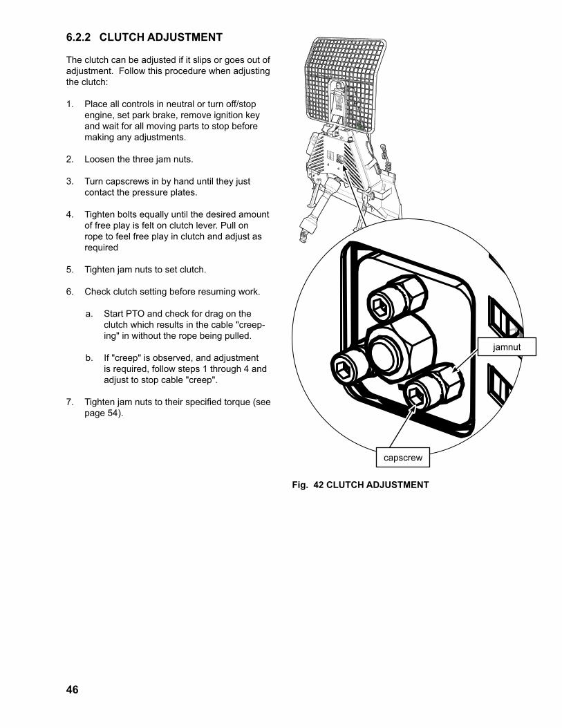
6.2.2 CLUTCH ADJUSTMENT
The clutch can be adjusted if it slips or goes out of adjustment. Follow this procedure when adjusting the clutch:
1. Place all controls in neutral or turn off/stop engine, set park brake, remove ignition key and wait for all moving parts to stop before making any adjustments.
2. Loosen the three jam nuts.
3. Turn capscrews in by hand until they just contact the pressure plates.
4. Tighten bolts equally until the desired amount of free play is felt on clutch lever. Pull on rope to feel free play in clutch and adjust as required
5. Tighten jam nuts to set clutch.
6. Check clutch setting before resuming work.
a. Start PTO and check for drag on the clutch which results in the cable "creep-ing" in without the rope being pulled.
b. If "creep" is observed, and adjustment is required, follow steps 1 through 4 and adjust to stop cable "creep".
7. Tighten jam nuts to their specified torque (see page 54).
Fig. 42 CLUTCH ADJUSTMENT
capscrew
jamnut

47
Fig. 43 ROLLER CHAIN TENSIONER
6.2.3 ROLLER CHAIN TENSIONER
NOTEThe nut should not contact the spring tension box during opera-tion.
The winch is designed with a roller chain to trans-mit the power between the PTO input and the clutch/winch. The chain tension is automatically set through a spring-loaded sliding tensioner.
The chain tensioning system is designed with an internal compression spring to set maximum chain tension during operation. When replacing the roller chain, follow this procedure to release ten-sion on the chain:
1. Place all controls in neutral, stop engine, set park brake, remove ignition key and wait for all moving parts to stop before making any adjustments.
2. Find the roller chain tension box ass'y at the side of the PTO
3. Turn in (tighten) the adjusting nut on tension bolt till chain tension is released (minimum chain tension).
4. Remove the old chain and install the new chain.
5. To set the chain to maximum tension: Turn out the adjusting nut on tension bolt within 1/4" (6 mm) from end of tension bolt.
Adjusting nut positions
Roller chain tension box ass'y
Maximum chain tension position
Minimum chain tension position

48
6.2.4 DRUM BRAKE ADJUSTMENT
Anchor Bolt
Anchor Bolt
Fig. 44 BRAKE BLOCK ADJUSTMENT
The winch is designed with a brake to stop the drum from turning when the brake is engaged. The brake must be set to hold the drum from freewheeling when the cable is not being pulled out to avoid tangling the cable.
When adjusting the brake, follow this proce-dure:
1. Place all controls in neutral, stop engine, set park brake, remove igni-tion key and wait for all moving parts to stop before making any adjustments.
2. Winch Brake Operation: When the cable is pulled off the drum,
it is routed over the top of the brake assembly arm. The force of pulling the cable off the drum, moves the arm to release the brake. When the cable is no longer being pulled on, the spring pulls the arm back and engages the brake. The brake must be set to stop the drum from freewheeling when the cable is not being pulled out to avoid tangling the cable.
3. Loosen jam nut on adjustment bolt.
4. Tighten the adjustment bolt until the brake just contacts the drum.
5. Tighten jam nut to its specified torque (see page 54).
7 TROUBLE SHOOTINGThe Wallenstein Skidding Winch is designed with a winch mounted in a frame to retract or extend a cable that attaches to a log or tree. It is a simple and reliable system that requires minimal maintenance.
In the following chart, we have listed many of the problems, causes and solutions to the problems that you may encounter.

49
If you encounter a problem that is difficult to solve, even after having read through this trouble shooting section, please call your local distributor or dealer. Before you call, please have this Operator's Manual from your unit and serial number ready.
Cable jammedDisengage winch or release brake, pull cable out and rewind cable on to the spool. Check winch brake.
Winch clutch disengaged
Engage winch clutch
PTO not on. Turn PTO on.
Clutch worn out. Replace clutch pads.Ensure machine is off / Call technician
Clutch out of adjustment.
Adjust clutch. Ensure machine is off
Broken shear pin. Replace pin and reduce size of load. Ensure machine is off
Winch lock engaged Disengage winch lock
Cable jammedDisengage winch or release brake, pull cable out and rewind cable on to the spool. Check winch brake.
Slow PTO speed. Increase PTO speed. (540 rpm max)
Pull harder on clutch rope.
Adjust clutch. Ensure machine is off
Replace worn clutch parts.Ensure machine is off / Call technician
Reduce load.
Greasy clutch pads - clean or replace clutch pads & assembly (improper chain lubrication)
Ensure machine is off / Call technician
Lock not engaged. Pull harder on lock rope.
Drum lock broken.Inspect and repair or replace lock mechanism.
Ensure machine is off / Call technician
Adjust brake block Ensure machine is off
Clean brake block (greasy) Ensure machine is off
Replace brake block (worn out)Ensure machine is off / Call technician
Repair damaged brake partsEnsure machine is off / Call technician
Cable pulls when clutch not engaged
Clutch out of adjustment.
Adjust clutch to prevent cable creep Ensure machine is off
Check chain tensioner, adjust. Ensure machine is off
Replace tension spring assembly.Ensure machine is off / Call technician
Drive sprocket misaligned, PTO shaft too long.
Check that PTO shaft is the correct length Ensure machine is off
PROBLEM CAUSE SOLUTION CAUTION
Slow cable retraction.Clutch slipping.
Winch doesn't lock.
Cable twists/jams and doesn't wind correctly
Winch Brake not working properly
Cable does not retract
Cable does not pull out
Winch jerks and shakes while in operation.
Chain loose

50
8 SPECIFICATIONS
SPECIFICATIONS SUBJECT TO CHANGE WITHOUT NOTICE
8.1 MECHANICAL
Model FX65 FX90 FX120
Pulling Capacity 6,500 lbs28.9 kN
9,000 lbs40 kN
12,000 lbs53.4 kN
Recommended Tractor Size 17-30 HP13-22.5 kW
30-80 HP22.5-60 kW
60-100 HP45-74.5 kW
Mounting (3 Pt Hitch) Category I Category I & II Category I & II
PTO Input Speed 540 RPM Max 540 RPM Max 540 RPM Max
Cable Speed @ 540 RPM 75-175 ft/min 22.8-53.3 m/min.
75-175 ft/min 22.8-53.3 m/min.
75-175 ft/min 22.8-53.3 m/min.
Cable Size 165' of 3/8" dia 50.29 m of 9.5 mm dia
165' of 3/8" dia 50.29 m of 9.5 mm dia
165' of 1/2" dia50.29 m of 12.7 mm dia
Clutch Type Mechanical, Dry Disk Mechanical, Dry Disk Mechanical, Dry Disk
Maximum Input Torque 398.25 ft-lbs 540 N-m
795.76 ft-lbs1,079 N-m
1.020 ft-lbs1,383 N-m
Maximum Bare Drum Pull 14,097 lbs62.7 kN
24,130 lbs107.4 kN
35,012 lbs155.7 kN
Maximum Full Drum Pull 4,931 lbs21.9 kN
7,963 lbs35.4 kN
11,795 lbs52.5 kN
Maximum Length of Cable 239 ft72.84 m
207.58 ft63.2 m
165 ft50.29 m
Weight 470 lbs213.2 kg
796 lbs361.0 kg
898 lbs407.3 kg
Height 53"134.62 cm
63"160.02 cm
67"170.18 cm
Width 40"101.6 cm
50.5"128.27 cm
58.5"148.59 cm

51
8.2 BOLT TORQUECHECKING BOLT TORQUE
The tables shown below give correct torque values for various bolts and capscrews. Tighten all bolts to the torques specified in chart unless otherwise noted. Check tightness of bolts periodically, using bolt torque chart as a guide. Replace hardware with the same strength bolt.
Torque figures indicated are valid for non-greased or non-oiled threads and heads unless otherwise specified. Therefore, do not grease or oil bolts or capscrews unless otherwise specified in this manual. When using locking elements, increase torque values by 5%.
* Torque value for bolts and capscrews are identified by their head markings.
1/4" 8 6 12 9 17 125/16" 13 10 25 19 36 273/8" 27 20 45 33 63 457/16" 41 30 72 53 100 751/2" 61 45 110 80 155 1159/16" 95 60 155 115 220 1655/8" 128 95 215 160 305 2203/4" 225 165 390 290 540 4007/8" 230 170 570 420 880 6501" 345 225 850 630 1320 970
Bolt Torque*
SAE 2 (N.m) (lb-ft)
SAE 5 (N.m) (lb-ft)
SAE 8 (N.m) (lb-ft)
Bolt Diamter
"A"
ENGLISH TORQUE SPECIFICATIONS
M3 0.5 0.4 1.8 1.3M4 3 2.2 4.5 3.3M5 6 4 9 7M6 10 7 15 11M8 25 18 35 26
M10 50 37 70 52M12 90 66 125 92M14 140 103 200 148M16 225 166 310 229M20 435 321 610 450M24 750 553 1050 774M30 1495 1103 2100 1550M36 2600 1917 3675 2710
BoltDiameter
"A"
Bolt Torque*8.8
(N.m) (lb-ft)10.9
(N.m) (lb-ft)
METRIC TORQUE SPECIFICATIONS

52
INDEXA
ATTACH ............................................................22B
BREAK-IN .........................................................20C
CABLE CONDITION .........................................28CE VERSION ...................................................21CHOKER CHAIN ..............................................33CLUTCH ...........................................................46COMPONENTS ................................................19CONTROLS ......................................................21
DDELIVERY INSPECTION ...................................4DETACHING .....................................................22DRIVELINE .......................................................17
CUTTING .....................................................17INSTALL .......................................................23MAINTENANCE ...........................................45PROPER LENGTH ......................................17E
EMERGENCY STOPPING ...............................28F
FIELD OPERATION .........................................25G
GREEN ROPE ..................................................21I
ILLUSTRATION ................................................43INTRODUCTION ................................................6
jjOB SITE ..........................................................25
KKEYHOLE SLIDERS ........................................34
LLOG CHAIN ......................................................32
MMAINTENANCE ...............................................45
OOPERATING HINTS .........................................38OPERATION .....................................................18
ATTACHING .................................................22BREAK-IN ....................................................20COMPONENTS ...........................................19CONTROLS .................................................21DETACH .......................................................24FIELD OPERATION .....................................25PRE-OPERATION CHECKLIST ..................20
OPERATOR POSITION ...................................29
PPRE-OPERATION CHECKLIST .......................20PTO ..................................................................17PTO DRIVELINE ..............................................17PTO INSTALL ...................................................23PULL ANGLE ....................................................30
RRETRACTING CABLE .....................................27
SSAFETY ..............................................................7
EQUIPMENT SAFETY GUIDELINES ............9GENERAL SAFETY .......................................8MAINTENANCE ........................................... 11PREPARATION ............................................ 11SAFETY SIGNS ...........................................10SAFETY TRAINING .....................................10SIGNAL WORDS ...........................................7SIGN-OFF FORM ........................................14STORAGE ....................................................13TRANSPORT ...............................................13
SAFETY SCREEN ............................................31SAFETY SIGN LOCATIONS ............................15
THREE PANEL ............................................15TWO PANEL ................................................16
SERIAL NUMBER ..............................................5SERVICE ..........................................................42SERVICE AND MAINTENANCE
SERVICE ILLUSTRATION ...........................43SERVICE RECORD .........................................44SHEAR BOLT ...................................................36SKIDDING ................................................. 27, 36SNATCHBLOCK ...............................................31STOPPING .......................................................28STORAGE ........................................................41
TTENSIONER .....................................................47TORQUE ..........................................................51TOW BAR .........................................................35TRACTOR POSITION ......................................30TRAINING ........................................................26
WWHITE ROPE ...................................................21WINCH CLUTCH ..............................................21WINCH LOCKOUT ...........................................21