Skid-Steer Rock Saw Drive Train Modification · PDF file•Skid steer attachment...
26
Skid-Steer Rock Saw Drive Train Modification Team Members Kelly Hogue Kristen Tucker Matthew Gassen Buck Melton by Prepared for CONEQTEC Universal and Senior Design - BAE 4022
Transcript of Skid-Steer Rock Saw Drive Train Modification · PDF file•Skid steer attachment...
Skid-Steer Rock Saw
Drive Train Modification
Team Members
Kelly Hogue Kristen Tucker
Matthew Gassen Buck Melton
by
Prepared for CONEQTEC Universal and Senior Design - BAE 4022
Project Sponsor
• CONEQTEC Universal
• Skid steer attachment manufacturer
• President Gary Cochran
Mission Statement
• Blue Diamond Machinery strives to
improve products by implementing high
quality designs, increasing efficiency, and
surpassing the demands of our clients.
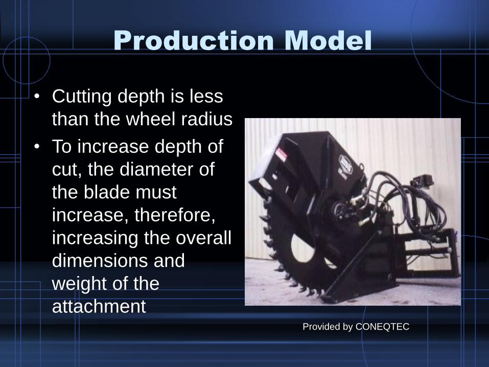
Production Model
• Cutting depth is less
than the wheel radius
• To increase depth of
cut, the diameter of
the blade must
increase, therefore,
increasing the overall
dimensions and
weight of the
attachmentProvided by CONEQTEC

Patent Search
• Slashing Loader – Ring & Pinion Gears
• Tree Harvester – Saw Blade
• Power Saw – Gears, Blade
• Concrete Saw – Debris Removal

CONEQTEC Rock Saw Prototype
Provided by Coneqtec
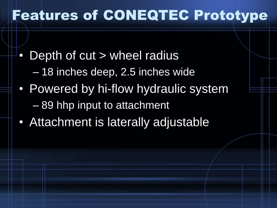
Features of CONEQTEC Prototype
• Depth of cut > wheel radius
– 18 inches deep, 2.5 inches wide
• Powered by hi-flow hydraulic system
– 89 hhp input to attachment
• Attachment is laterally adjustable

Hydraulic System Specifications
Hydraulic Power Kits A B C
Flow (gpm) 34 40 33
Pressure (psi) 4500 3200 4060
Power (hhp) 89 75 78
Hydraulic Motor
Displacement (cc) 200 200 200
RPM 320 380 310
Torque (ft lbs) 730 520 660
Total Force (lbs) 450 320 410
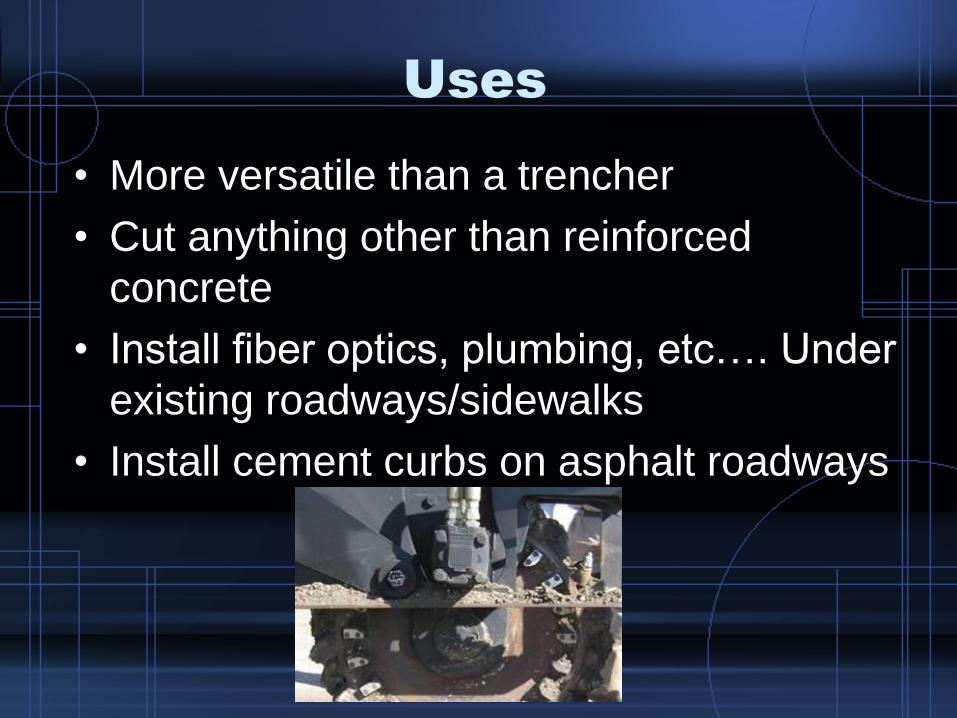
Uses
• More versatile than a trencher
• Cut anything other than reinforced
concrete
• Install fiber optics, plumbing, etc…. Under
existing roadways/sidewalks
• Install cement curbs on asphalt roadways
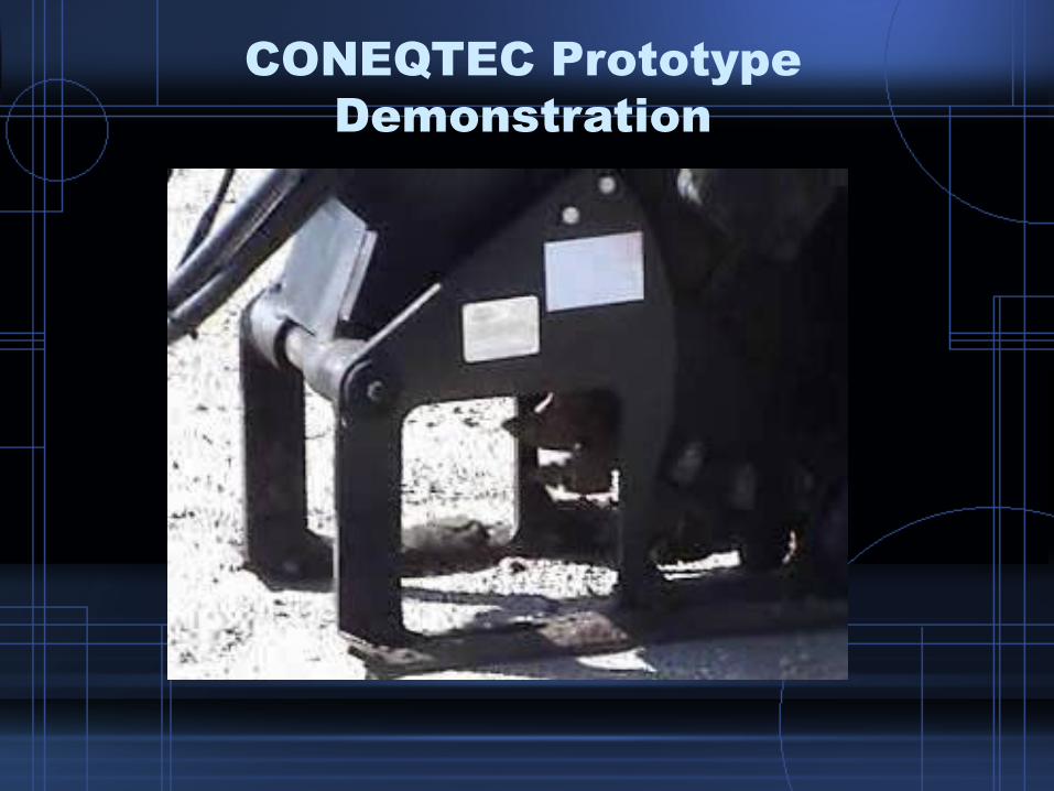
CONEQTEC Prototype
Demonstration
Problem Statement
• Increase cutting depth to greater than
blade radius
• Modify CONEQTEC prototype to
increase useful life
• Prevent hydraulic motors from running in
debris piles
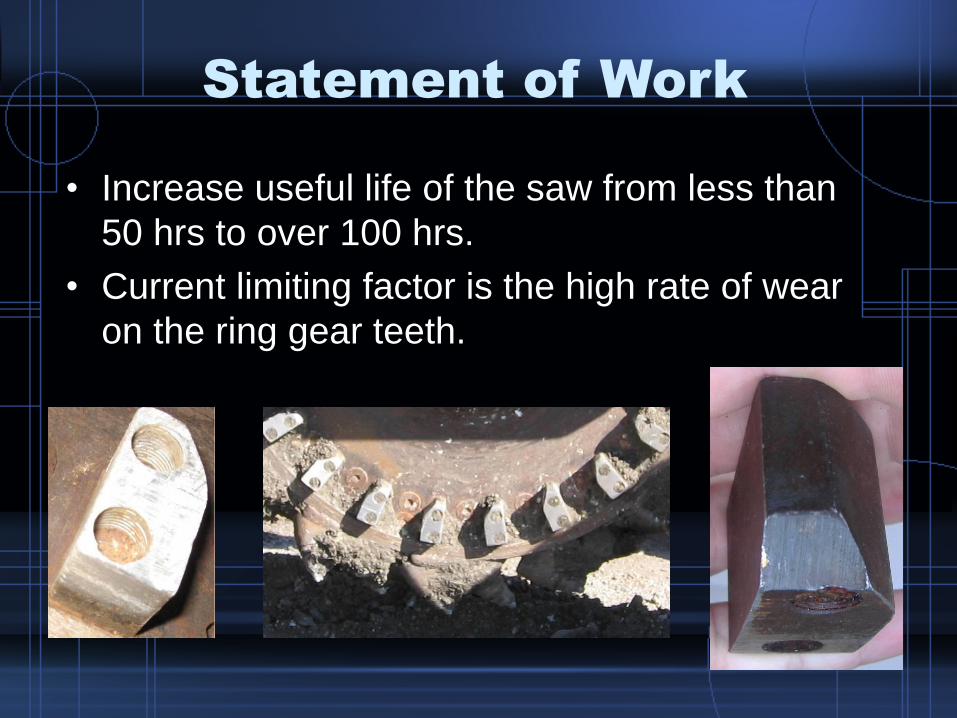
Statement of Work
• Increase useful life of the saw from less than
50 hrs to over 100 hrs.
• Current limiting factor is the high rate of wear
on the ring gear teeth.
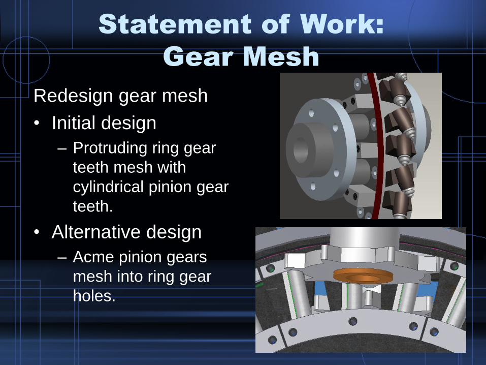
Statement of Work:
Gear Mesh
Redesign gear mesh
• Initial design
– Protruding ring gear
teeth mesh with
cylindrical pinion gear
teeth.
• Alternative design
– Acme pinion gears
mesh into ring gear
holes.
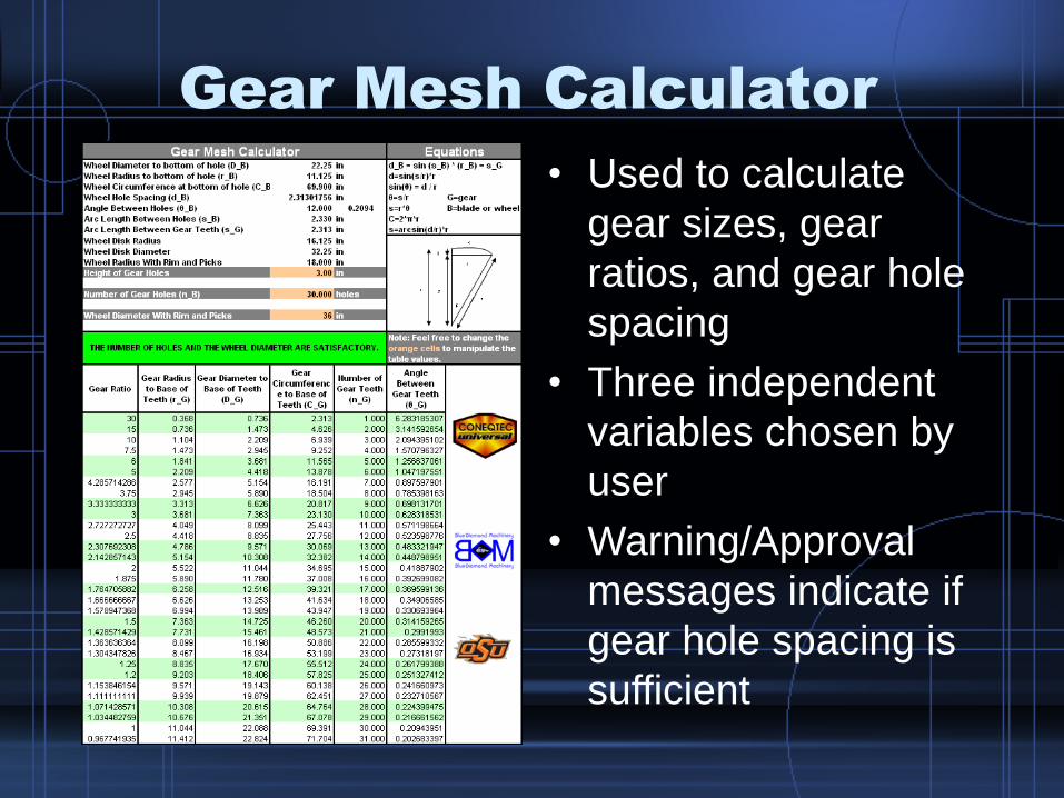
Gear Mesh Calculator
• Used to calculate
gear sizes, gear
ratios, and gear hole
spacing
• Three independent
variables chosen by
user
• Warning/Approval
messages indicate if
gear hole spacing is
sufficient

Gear Specifications
• 2 Gears – 7 teeth
• 3/4” thick steel
• 1/4” spacing between gears
• Top Gear– Dedendum circle diameter
(D): 6.16”
– Addendum circle diameter (A): 8.08”
• Bottom Gear– Dedendum circle diameter
(D): 5.76”
– Addendum circle diameter (A): 7.62”
D
A

Wheel and Gear Specifications
Hydraulic Power Kits A B C
Cutting Wheel
RPM 75 88 73
Torque (ft lbs) 3100 2200 2800
Force (lbs) 8300 5900 7500
Ring Gear Holes
Shear Force (psi) 1000 720 910
Pinion Gear
Shear Force (psi) 300 220 270
Fatigue Load (psi) 41,000

Ring Gear Evolution
CONEQTEC PROTOTYPE BDM PROTOTYPE
BDM PROTOTYPE INSERT PROGRESSION
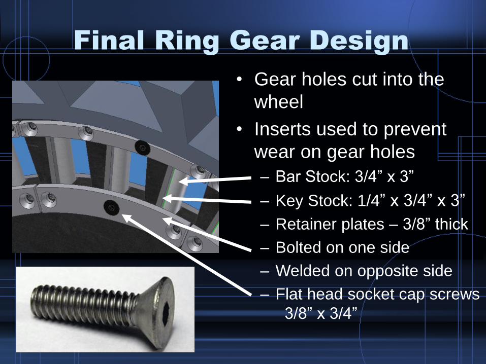
Final Ring Gear Design
• Gear holes cut into the
wheel
• Inserts used to prevent
wear on gear holes
– Bar Stock: 3/4” x 3”
– Key Stock: 1/4” x 3/4” x 3”
– Retainer plates – 3/8” thick
– Bolted on one side
– Welded on opposite side
– Flat head socket cap screws
3/8” x 3/4”

BDM Gear Mesh Demonstration

Statement of Work: Motors
• Prevent hydraulic motors from running in
debris
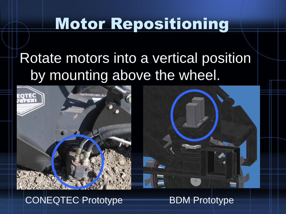
Motor Repositioning
Rotate motors into a vertical position
by mounting above the wheel.
CONEQTEC Prototype BDM Prototype
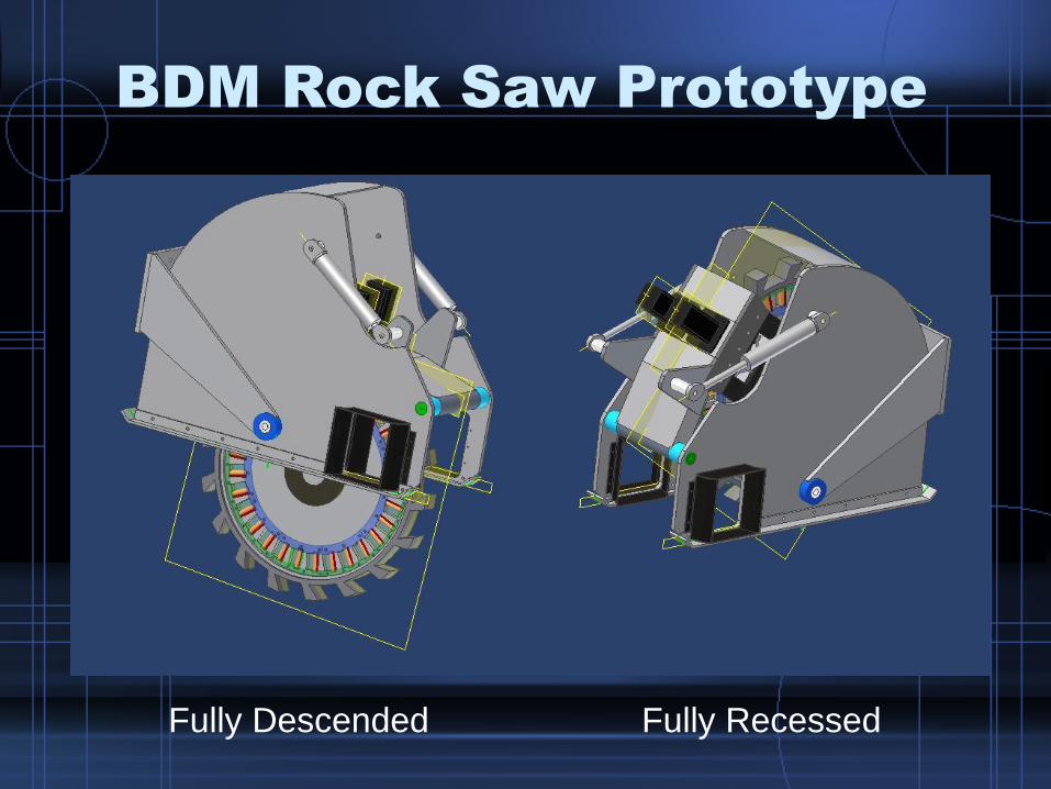
BDM Rock Saw Prototype
Fully Descended Fully Recessed

Budget
Materials $1,623
Fasteners $112
Tools $36
Total $1,772
Recommendations
• Replace gear shafts by using hydraulic motors with wheel mount flange
• Make motors vertically and laterally adjustable to allow for gear adjustability
• Attach a front debris flap for added safety
• Holes could be added to outer frame to reduce weight and increase ease of maintenance
Recognitions
• Gary Cochran – CONEQTEC Universal
• Dennis Skraba – CONEQTEC Universal
• Dr. Paul Weckler – OSU BAE Senior Design Professor and Advisor
• Wayne Kiner – OSU BAE Laboratory Manager
• Bobby Flores, Robert Harrington,
and Robert Harshman – OSU BAE Laboratory
• Stillwater Steel – Fabrication
• Steve Miller – Interstate Tool – Fabrication
• Railroad Yard – Fabrication
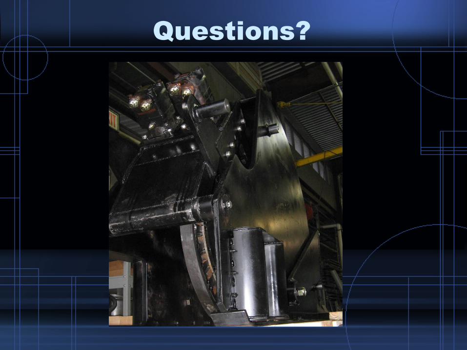
Questions?