SKF Vibration Sensors Catalog · 2 Introduction The measurement of vibration is the most common...
104
SKF Vibration Sensors Catalog Vibration sensors, sensor selection, installation and mounting, cables and connectors, mounting accessories
-
Upload
nguyenkiet -
Category
Documents
-
view
217 -
download
0
Transcript of SKF Vibration Sensors Catalog · 2 Introduction The measurement of vibration is the most common...
SKF Vibration Sensors CatalogVibration sensors, sensor selection, installation and mounting, cables and connectors, mounting accessories
ContentsIntroduction 2
Vibration sensor selection 3
Pulp and Paper 4
General purpose, food and beverage 5
Oil and gas, reining, petrochemicals 6
Power generation (fossil fuel, nuclear, hydro) 7
Power generation (wind turbines) 8
Metals 9
Mining, mineral processing and cement 10
Industrial accelerometers for widespread applications 11
Accelerometers with extended temperature range 34
Combination vibration and temperature sensors 39
Hazardous area approved sensors 52
Portable analysis accelerometers 69
Special purpose sensors 74
Low-frequency accelerometers 75
Vibration sensor installation and mounting requirements 79
Vibration sensor cables and accessories 88
Mounting hardware 97
1
2
IntroductionThe measurement of vibration is the most
common method of assessing the mechani-
cal status of machinery for condition moni-
toring purposes
Although advances have been made in the
ield of vibration monitoring and analysis
equipment, the selection of sensors and the
way they are installed on a machine remain
critical factors in determining the success of
any condition monitoring program Invest-
ments made for installing superior sensors
are a prudent investment since the informa-
tion provided about the machine of interest
is accurate and reliable Poor quality sensors
and inadequate installation can easily give
misleading data or, in some cases, cause a
critical machine condition to be completely
overlooked
SKF has developed a range of industrial
vibration sensors that incorporates over
three decades of practical experience from
providing transducers such as eddy current
probe displacement sensors, accelerometers
and velocity sensors, to machinery monitor-
ing of all classes in multiple industries
The measurements of vibration
The three parameters representing motion
detected by vibration monitors are:
• Displacement
• Velocity
• Acceleration
These parameters can be measured by a
variety of motion sensors and are mathe-
matically related:
• Velocity is the irst time derivative of
displacement
• Acceleration is the irst time derivative of
velocity
Selection of a sensor proportional to dis-
placement, velocity or acceleration depends
upon the type and design of the equipment
that is to be monitored, the frequencies of
interest and the signal levels involved
Displacement sensors
Eddy current probes are non-contact sen-
sors primarily used to measure displace-
ment that relects shaft radial vibration,
shaft/rotor position and clearance and rota-
tional speed Also referred to as “proximity
probes” or “displacement probes”, eddy cur-
rent probes are typically applied on
machines utilizing sleeve/journal bearings
They have excellent frequency response with
no lower frequency limit and can also be
used to provide a trigger input for phase-re-
lated measurements Eddy current probe
systems are the best solution for shaft posi-
tion measurements in sleeve bearing equip-
ment The selection and speciications of
SKF’s range of eddy current probes is
detailed in a separate catalog
Velocity sensors
Velocity sensors are used for low to medium
frequency measurements They are useful
for vibration monitoring and balancing oper-
ations on rotating machinery As compared
to accelerometers, velocity sensors have
lower sensitivity to high frequency vibra-
tions There are two types:
• Traditional, “self-generating” velocity sen-
sors or “velocity pickups” These are of a
mechanical design that use an electro-
magnetic (coil and magnet) system to
generate the velocity signal Their advan-
tage is a direct measurement of velocity
Their disadvantages are that they wear
out over time, owing to the moving parts,
and are sensitive to mounting orientation
• Piezoelectric velocity sensors (internally
integrated accelerometers) These are
more common today, as they have
improved capabilities over self-generating
types and are a more rugged and smaller
size design
AccelerometersThe acceleration sensor is versatile, reliable
and the most popular vibration sensor for
machinery monitoring For a given mechani-
cal acceleration level, piezoelectric acceler-
ometers have a constant signal over a wide
frequency range, typically up to 20 kHz, and
are very useful for all types of vibration
measurements Acceleration integrated to
velocity can be used for low frequency
measurements Acceleration signals in the
high frequency range added with various
signal processing techniques like Accelera-
tion Enveloping (gE) are very useful for
bearing and gear measurements
The basic acceleration sensor has a good
signal to noise ratio over a wide dynamic
range They are useful for measuring low to
very high frequencies and are available in a
wide variety of general purpose and applica-
tion speciic designs
When combined with vibration monitors
capable of integrating from acceleration to
velocity, accelerometers can be useful com-
ponents in a multi-parameter monitoring
program
Sensor wiring, mounting hardware and accessoriesIn addition to sensor selection, sensor
mounting and wiring are important aspect of
vibration sensor installation As with sensors
and monitoring equipment, using superior
installation components is a good invest-
ment Time and effort to troubleshoot prob-
lems related to poor cabling and inferior
mounting can easily exceed the original cost
of an inferior installation
SKF offers a comprehensive product line
of sensor wiring, mounting hardware and
accessories These are the same compo-
nents that SKF uses in its own bearing man-
ufacturing plants and for customer systems
that are installed and maintained under SKF
service contracts

3
Vibration sensor selection
The range of vibration sensors offered is wide, as a vibration sensor
has many different characteristics that may vary, including measure-
ment related factors such as frequency response, sensitivity and
accuracy Physical characteristics such as temperature rating, size
and connector orientation are also considerations
The following is a guide to SKF’s experience in sensor use in the
most common industrial sectors in which vibration monitoring is
employed
For each industry, the top four features required of a quality vibra-
tion sensor are stated and explained Industrial sensor choices are
graded:
• “Good” – A general purpose choice that has adequate measure-
ment and physical characteristics for condition monitoring pro-
grams, where data is trended for change and absolute precision is
not so important
• “Better” – A general purpose choice that has adequate measure-
ment and physical characteristics for condition monitoring pro-
grams, but adds a speciic feature such as an extended tempera-
ture range or mounting orientation better suited to the application
• “Best” – A premium choice that has optimum measurement and
physical characteristics, but also offers the longest history as evi-
dence of reliability These are particularly suited to critical machin-
ery applications where the sensor may be used in safety-related
functions such as machinery protection
4
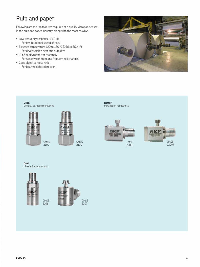
Pulp and paperFollowing are the top features required of a quality vibration sensor
in the pulp and paper industry, along with the reasons why:
• Low frequency response ≤ 1,0 Hz
– For low rotational speed of rolls
• Elevated temperature 120 to 150 °C (250 to 300 °F)
– For dryer section heat and humidity
• IP 68 cable/connector assembly
– For wet environment and frequent roll changes
• Good signal to noise ratio
– For bearing defect detection
CMSS 2100
CMSS 2100T
CMSS 2200T
CMSS 2200
CMSS 2207
CMSS 2106
GoodGeneral purpose monitoring
BestElevated temperatures
BetterInstallation robustness
5
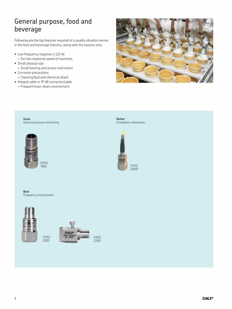
General purpose, food and beverage
Following are the top features required of a quality vibration sensor
in the food and beverage industry, along with the reasons why:
• Low frequency response ≤ 1,0 Hz
– For low rotational speed of machines
• Small physical size
– Small bearing and access restrictions
• Corrosion precautions
– Cleaning luid and chemical attack
• Integral cable or IP 68 connector/cable
– Frequent hose-down environment
CMSS 780C CMSS
2100F
CMSS 2100
CMSS 2200
GoodGeneral purpose monitoring
BestFrequency and precision
BetterInstallation robustness
6
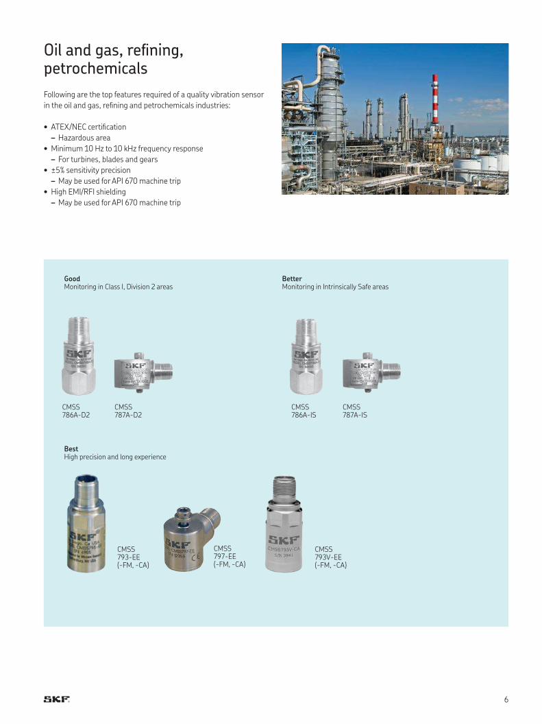
Oil and gas, reining, petrochemicals
Following are the top features required of a quality vibration sensor
in the oil and gas, reining and petrochemicals industries:
• ATEX/NEC certiication
– Hazardous area
• Minimum 10 Hz to 10 kHz frequency response
– For turbines, blades and gears
• ±5% sensitivity precision
– May be used for API 670 machine trip
• High EMI/RFI shielding
– May be used for API 670 machine trip
CMSS 797-EE (-FM, -CA)
CMSS 793-EE (-FM, -CA)
CMSS 786A-D2
CMSS 786A-IS
CMSS 787A-D2
CMSS 787A-IS
CMSS 793V-EE (-FM, -CA)
GoodMonitoring in Class I, Division 2 areas
BestHigh precision and long experience
BetterMonitoring in Intrinsically Safe areas
7
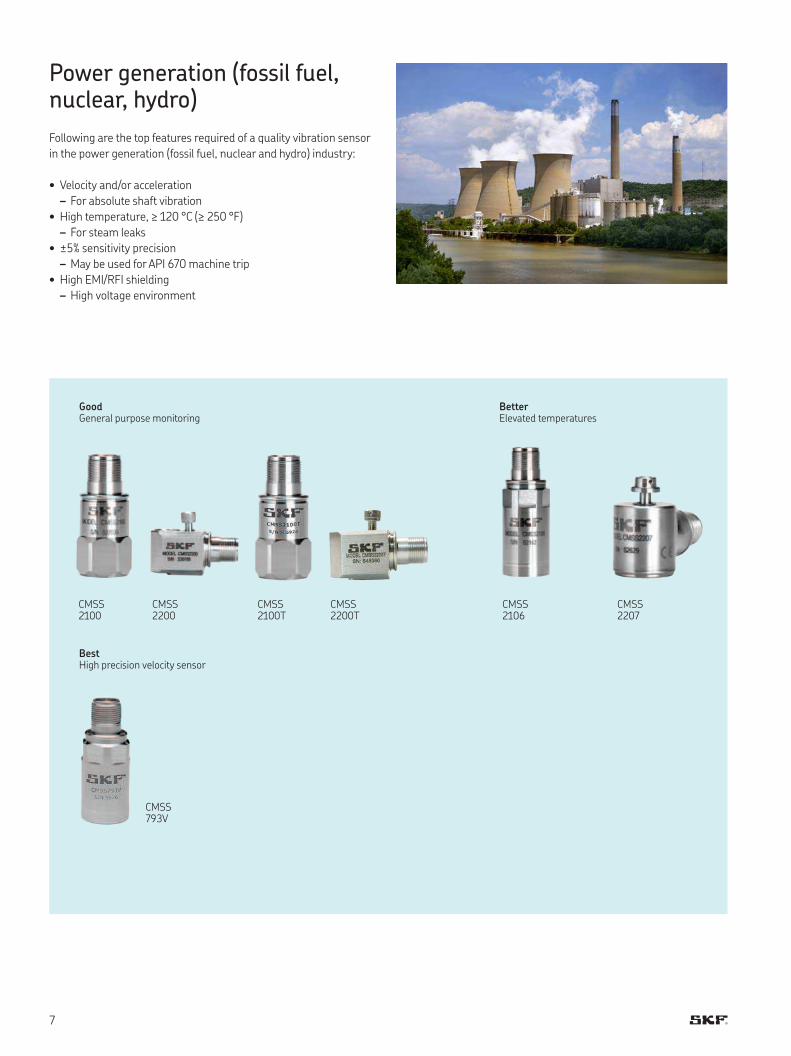
Power generation (fossil fuel, nuclear, hydro)
Following are the top features required of a quality vibration sensor
in the power generation (fossil fuel, nuclear and hydro) industry:
• Velocity and/or acceleration
– For absolute shaft vibration
• High temperature, ≥ 120 °C (≥ 250 °F)
– For steam leaks
• ±5% sensitivity precision
– May be used for API 670 machine trip
• High EMI/RFI shielding
– High voltage environment
CMSS 2100
CMSS 2100T
CMSS 2200
CMSS 2200T
CMSS 2106
CMSS 2207
CMSS 793V
GoodGeneral purpose monitoring
BestHigh precision velocity sensor
BetterElevated temperatures
8
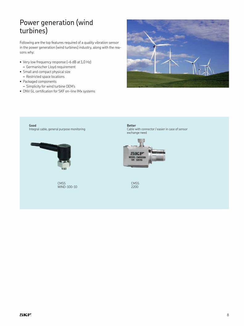
Power generation (wind turbines)
Following are the top features required of a quality vibration sensor
in the power generation (wind turbines) industry, along with the rea-
sons why:
• Very low frequency response (–6 dB at 1,0 Hz)
– Germanischer Lloyd requirement
• Small and compact physical size
– Restricted space locations
• Packaged components
– Simplicity for wind turbine OEM’s
• DNV GL certiication for SKF on-line IMx systems
CMSS WIND-100-10
CMSS 2200
GoodIntegral cable, general purpose monitoring
BetterCable with connector / easier in case of sensor exchange need
9
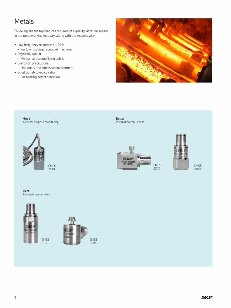
MetalsFollowing are the top features required of a quality vibration sensor
in the metalworking industry, along with the reasons why:
• Low frequency response ≤ 1,0 Hz
– For low rotational speed of machines
• Physically robust
– Misuse, abuse and lying debris
• Corrosion precautions
– Hot, dusty and corrosive environment
• Good signal-to-noise ratio
– For bearing defect detection
CMSS 2110
CMSS 2100
CMSS 2200
CMSS 2106
CMSS 2207
GoodGeneral purpose monitoring
BestElevated temperature
BetterInstallation robustness
10
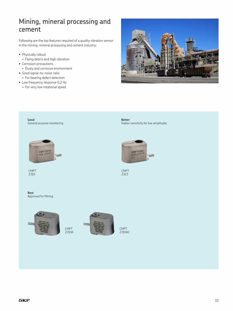
Mining, mineral processing and cement
Following are the top features required of a quality vibration sensor
in the mining, mineral processing and cement industry:
• Physically robust
– Flying debris and high vibration
• Corrosion precautions
– Dusty and corrosive environment
• Good signal-to-noise ratio
– For bearing defect detection
• Low frequency response 0,2 Hz
– For very low rotational speed
CMPT 2310AC
CMPT 2310A
CMPT 2310
CMPT 2323
GoodGeneral purpose monitoring
BestApproved for Mining
BetterHigher sensitivity for low amplitudes
1111
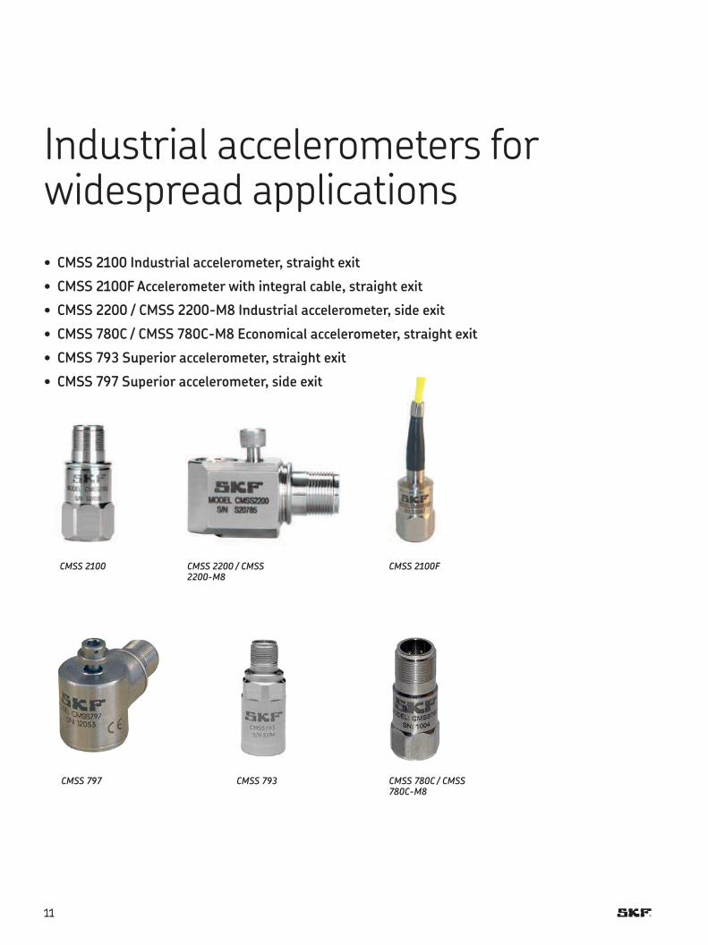
Industrial accelerometers for widespread applications
• CMSS 2100 Industrial accelerometer, straight exit
• CMSS 2100F Accelerometer with integral cable, straight exit
• CMSS 2200 / CMSS 2200-M8 Industrial accelerometer, side exit
• CMSS 780C / CMSS 780C-M8 Economical accelerometer, straight exit
• CMSS 793 Superior accelerometer, straight exit
• CMSS 797 Superior accelerometer, side exit
CMSS 2100 CMSS 2200 / CMSS 2200-M8
CMSS 2100F
CMSS 793 CMSS 780C / CMSS 780C-M8
CMSS 797
1212
A
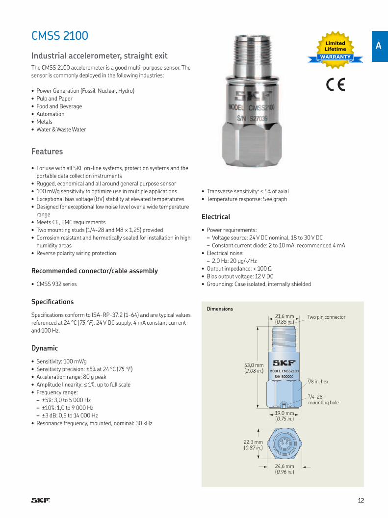
CMSS 2100
Industrial accelerometer, straight exit
The CMSS 2100 accelerometer is a good multi-purpose sensor The
sensor is commonly deployed in the following industries:
• Power Generation (Fossil, Nuclear, Hydro)
• Pulp and Paper
• Food and Beverage
• Automation
• Metals
• Water & Waste Water
Features
• For use with all SKF on-line systems, protection systems and the
portable data collection instruments
• Rugged, economical and all around general purpose sensor
• 100 mV/g sensitivity to optimize use in multiple applications
• Exceptional bias voltage (BV) stability at elevated temperatures
• Designed for exceptional low noise level over a wide temperature
range
• Meets CE, EMC requirements
• Two mounting studs (1/4-28 and M8 × 1,25) provided
• Corrosion resistant and hermetically sealed for installation in high
humidity areas
• Reverse polarity wiring protection
Recommended connector/cable assembly
• CMSS 932 series
Speciications
Speciications conform to ISA-RP-37 2 (1-64) and are typical values
referenced at 24 °C (75 °F), 24 V DC supply, 4 mA constant current
and 100 Hz
Dynamic
• Sensitivity: 100 mV/g
• Sensitivity precision: ±5% at 24 °C (75 °F)
• Acceleration range: 80 g peak
• Amplitude linearity: ≤ 1%, up to full scale
• Frequency range:
– ±5%: 3,0 to 5 000 Hz
– ±10%: 1,0 to 9 000 Hz
– ±3 dB: 0,5 to 14 000 Hz
• Resonance frequency, mounted, nominal: 30 kHz
• Transverse sensitivity: ≤ 5% of axial
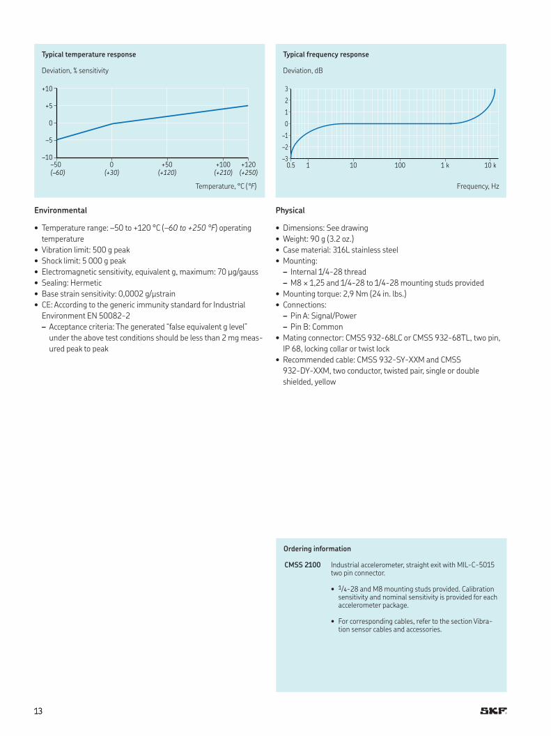
• Temperature response: See graph
Electrical
• Power requirements:
– Voltage source: 24 V DC nominal, 18 to 30 V DC
– Constant current diode: 2 to 10 mA, recommended 4 mA
• Electrical noise:
– 2,0 Hz: 20 µg/√Hz
• Output impedance: < 100 Ω
• Bias output voltage: 12 V DC
• Grounding: Case isolated, internally shielded
Limited
Lifetime
WARRANTY
Dimensions
MODEL CMSS2100
S/N S00000
A B
Two pin connector
53,0 mm (2.08 in.)
24,6 mm (0.96 in.)
22,3 mm (0.87 in.)
19,0 mm (0.75 in )
21,6 mm (0.85 in )
1/4-28 mounting hole
7/8 in hex
1313
+ 1 0
+ 5
0
– 5
– 1 0
– 5 0 0 + 5 0 + 1 0 0 + 1 2 0
(–60) (+30) (+120) (+210) (+250)
Typical temperature response
Deviation, % sensitivity
3
2
1
0
–1
–2
–30.5 1 10 100 1 k 10 k
Typical frequency response
Deviation, dB
Temperature, °C (°F) Frequency, Hz
Environmental
• Temperature range: –50 to +120 °C (–60 to +250 °F) operating
temperature
• Vibration limit: 500 g peak
• Shock limit: 5 000 g peak
• Electromagnetic sensitivity, equivalent g, maximum: 70 µg/gauss
• Sealing: Hermetic
• Base strain sensitivity: 0,0002 g/μstrain
• CE: According to the generic immunity standard for Industrial
Environment EN 50082-2
– Acceptance criteria: The generated “false equivalent g level”
under the above test conditions should be less than 2 mg meas-
ured peak to peak
Physical
• Dimensions: See drawing
• Weight: 90 g (3 2 oz )
• Case material: 316L stainless steel
• Mounting:
– Internal 1/4-28 thread
– M8 × 1,25 and 1/4-28 to 1/4-28 mounting studs provided
• Mounting torque: 2,9 Nm (24 in lbs )
• Connections:
– Pin A: Signal/Power
– Pin B: Common
• Mating connector: CMSS 932-68LC or CMSS 932-68TL, two pin,
IP 68, locking collar or twist lock
• Recommended cable: CMSS 932-SY-XXM and CMSS
932-DY-XXM, two conductor, twisted pair, single or double
shielded, yellow
Ordering information
CMSS 2100 Industrial accelerometer, straight exit with MIL-C-5015 two pin connector
• 1/4-28 and M8 mounting studs provided Calibration sensitivity and nominal sensitivity is provided for each accelerometer package
• For corresponding cables, refer to the section Vibra-tion sensor cables and accessories
1414
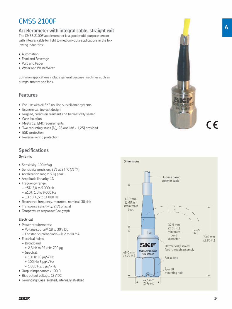
A
CMSS 2100FAccelerometer with integral cable, straight exitThe CMSS 2100F accelerometer is a good multi-purpose sensor
with integral cable for light to medium-duty applications in the fol-
lowing industries:
• Automation
• Food and Beverage
• Pulp and Paper
• Water and Waste Water
Common applications include general purpose machines such as
pumps, motors and fans
Features
• For use with all SKF on-line surveillance systems
• Economical, top exit design
• Rugged, corrosion resistant and hermetically sealed
• Case isolation
• Meets CE, EMC requirements
• Two mounting studs (1/4-28 and M8 × 1,25) provided
• ESD protection
• Reverse wiring protection
SpeciicationsDynamic
• Sensitivity: 100 mV/g
• Sensitivity precision: ±5% at 24 °C (75 °F)
• Acceleration range: 80 g peak
• Amplitude linearity: 1%
• Frequency range:
– ±5%: 3,0 to 5 000 Hz
– ±10%: 1,0 to 9 000 Hz
– ±3 dB: 0,5 to 14 000 Hz
• Resonance frequency, mounted, nominal: 30 kHz
• Transverse sensitivity: ≤ 5% of axial
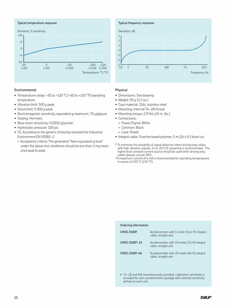
• Temperature response: See graph
Electrical
• Power requirements:
– Voltage source1): 18 to 30 V DC
– Constant current diode1), 2): 2 to 10 mA
• Electrical noise:
– Broadband:
2,5 Hz to 25 kHz: 700 µg
– Spectral:
10 Hz: 10 µg/√Hz
100 Hz: 5 µg/√Hz
1 000 Hz: 5 µg/√Hz
• Output impedance: < 100 Ω
• Bias output voltage: 12 V DC
• Grounding: Case isolated, internally shielded
Dimensions
MODEL CMSS2100F
S/N S00000
Fluorine based polymer cable
42,7 mm (1.68 in.)
strain relief boot
45,0 mm (1.77 in.)
24,6 mm(0.96 in.)
37,5 mm (1.50 in.) minimum
bend diameter
70,0 mm (2.80 in.)
Hermetically sealed feed-through assembly
7/8 in. hex
1/4-28 mounting hole
1515
Ordering information
CMSS 2100F Accelerometer with 5 meter (16,4 ft) integral cable, straight exit.
CMSS 2100F-33 Accelerometer with 10 meter (33 ft) integral cable, straight exit.
CMSS 2100F-66 Accelerometer with 20 meter (66 ft) integral cable, straight exit.
Physical
• Dimensions: See drawing
• Weight: 90 g (3.2 oz.)
• Case material: 316L stainless steel
• Mounting: Internal 1/4-28 thread
• Mounting torque: 2,9 Nm (24 in. lbs.)
• Connections:
– Power/Signal: White
– Common: Black
– Case: Shield
• Integral cable: Fluorine based polymer, 5 m (16.4 ft.) blunt cut
1) To minimize the possibility of signal distortion when driving long cables with high vibration signals, 24 to 30 V DC powering is recommended. The higher level constant current source should be used when driving long cables (please consult SKF).
2) A maximum current of 6 mA is recommended for operating temperatures in excess of 100 °C (210 °F).
Environmental
• Temperature range: –50 to +120 °C (–60 to +250 °F) operating
temperature
• Vibration limit: 500 g peak
• Shock limit: 5 000 g peak
• Electromagnetic sensitivity, equivalent g maximum: 70 µg/gauss
• Sealing: Hermetic
• Base strain sensitivity: 0,0002 g/µstrain
• Hydrostatic pressure: 100 psi
• CE: According to the generic immunity standard for Industrial
Environment EN 50082-2
– Acceptance criteria: The generated “false equivalent g level”
under the above test conditions should be less than 2 mg meas-
ured peak to peak
Typical temperature response
Temperature, °C (°F)
Deviation, % sensitivity
+10
+5
0
–5
–10–50 0 +50 +100 +120
(–60) (+30) (+120) (+210) (+250)
Typical frequency response
Frequency, Hz
Deviation, dB
3
2
1
0
–1
–2
–30.5 1 10 100 1 k 10 k
• 1/4-28 and M8 mounting studs provided. Calibration sensitivity is provided for each accelerometer package with nominal sensitivity etched on each unit.
1616
A
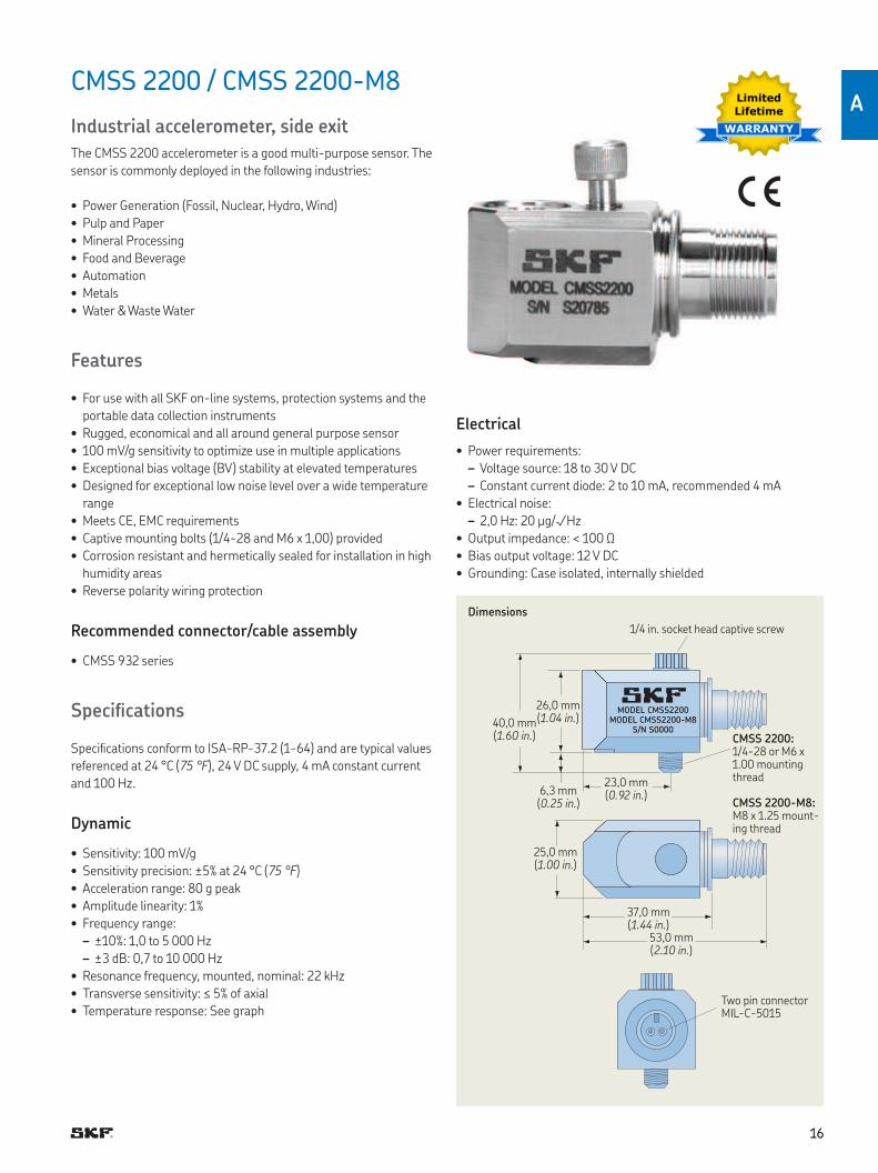
CMSS 2200 / CMSS 2200-M8
Industrial accelerometer, side exit
The CMSS 2200 accelerometer is a good multi-purpose sensor The
sensor is commonly deployed in the following industries:
• Power Generation (Fossil, Nuclear, Hydro, Wind)
• Pulp and Paper
• Mineral Processing
• Food and Beverage
• Automation
• Metals
• Water & Waste Water
Features
• For use with all SKF on-line systems, protection systems and the
portable data collection instruments
• Rugged, economical and all around general purpose sensor
• 100 mV/g sensitivity to optimize use in multiple applications
• Exceptional bias voltage (BV) stability at elevated temperatures
• Designed for exceptional low noise level over a wide temperature
range
• Meets CE, EMC requirements
• Captive mounting bolts (1/4-28 and M6 x 1,00) provided
• Corrosion resistant and hermetically sealed for installation in high
humidity areas
• Reverse polarity wiring protection
Recommended connector/cable assembly
• CMSS 932 series
Speciications
Speciications conform to ISA-RP-37 2 (1-64) and are typical values
referenced at 24 °C (75 °F), 24 V DC supply, 4 mA constant current
and 100 Hz
Dynamic
• Sensitivity: 100 mV/g
• Sensitivity precision: ±5% at 24 °C (75 °F)
• Acceleration range: 80 g peak
• Amplitude linearity: 1%
• Frequency range:
– ±10%: 1,0 to 5 000 Hz
– ±3 dB: 0,7 to 10 000 Hz
• Resonance frequency, mounted, nominal: 22 kHz
• Transverse sensitivity: ≤ 5% of axial
• Temperature response: See graph
Electrical
• Power requirements:
– Voltage source: 18 to 30 V DC
– Constant current diode: 2 to 10 mA, recommended 4 mA
• Electrical noise:
– 2,0 Hz: 20 µg/√Hz
• Output impedance: < 100 Ω
• Bias output voltage: 12 V DC
• Grounding: Case isolated, internally shielded
Limited
Lifetime
WARRANTY
MODEL CMSS2200MODEL CMSS2200-M8
S/N S0000
Dimensions
1/4 in socket head captive screw
26,0 mm(1.04 in.)
23,0 mm(0.92 in.)
40,0 mm(1.60 in.)
6,3 mm(0.25 in.)
25,0 mm(1.00 in.)
53,0 mm (2.10 in.)
37,0 mm (1.44 in.)
Two pin connector MIL-C-5015
CMSS 2200:1/4-28 or M6 x 1 00 mounting thread
CMSS 2200-M8:M8 x 1 25 mount-ing thread
1717
+10
+5
0
–5
–10
–50 0 +50 +100 +120
(–60) (+30) (+120) (+210) (+250)
Typical temperature response
Deviation, % sensitivity
3
2
1
0
–1
–2
–30.7 1 10 100 1 k 10 k
Typical frequency response
Deviation, dB
Temperature, °C (°F) Frequency, Hz
Environmental
• Temperature range: –50 to +120 °C (–60 to +250 °F) operating
temperature
• Vibration limit: 500 g peak
• Shock limit: 5 000 g
• Electromagnetic sensitivity, equivalent g, maximum: 30 µg/gauss
• Sealing: Hermetic
• Base strain sensitivity: 0,002 g/µstrain
• CE: According to the generic immunity standard for Industrial
Environment EN 50082-2
– Acceptance criteria: The generated “false equivalent g level”
under the above test conditions should be less than 2 mg meas-
ured peak to peak
Physical
• Dimensions: See drawing
• Weight: 135 g (4.8 oz.)
• Case material: 316L stainless steel
• Mounting: 1/4-28 and M6 x 1 captive socket head screw
• Mounting torque: 2,9 Nm (24 in lbs )
• Connections:
– Shell: Ground
– Pin A: Power/Signal
– Pin B: Common
• Mating connector: CMSS 932-68LC or CMSS 932-68TL, two pin,
IP 68, locking collar or twist lock
• Recommended cable: CMSS 932-SY-XXM and CMSS
932-DY-XXM, two conductor, twisted pair, single shielded, yellow
Ordering information
CMSS 2200 CMSS 2200 Industrial accelerometer with side exit MIL-C-5015 two pin connector
CMSS 2200-M8
• 1/4-28 and M6 captive socket head screws provided Calibration sensitivity and nominal sensitivity is pro-vided for each accelerometer package
CMSS 2200-M8 Industrial accelerometer with side exit MIL-C-5015 two pin connector
• M8 x 1,25 captive socket head screw provided Cali-bration sensitivity and nominal sensitivity is provided for each accelerometer package
1818
A
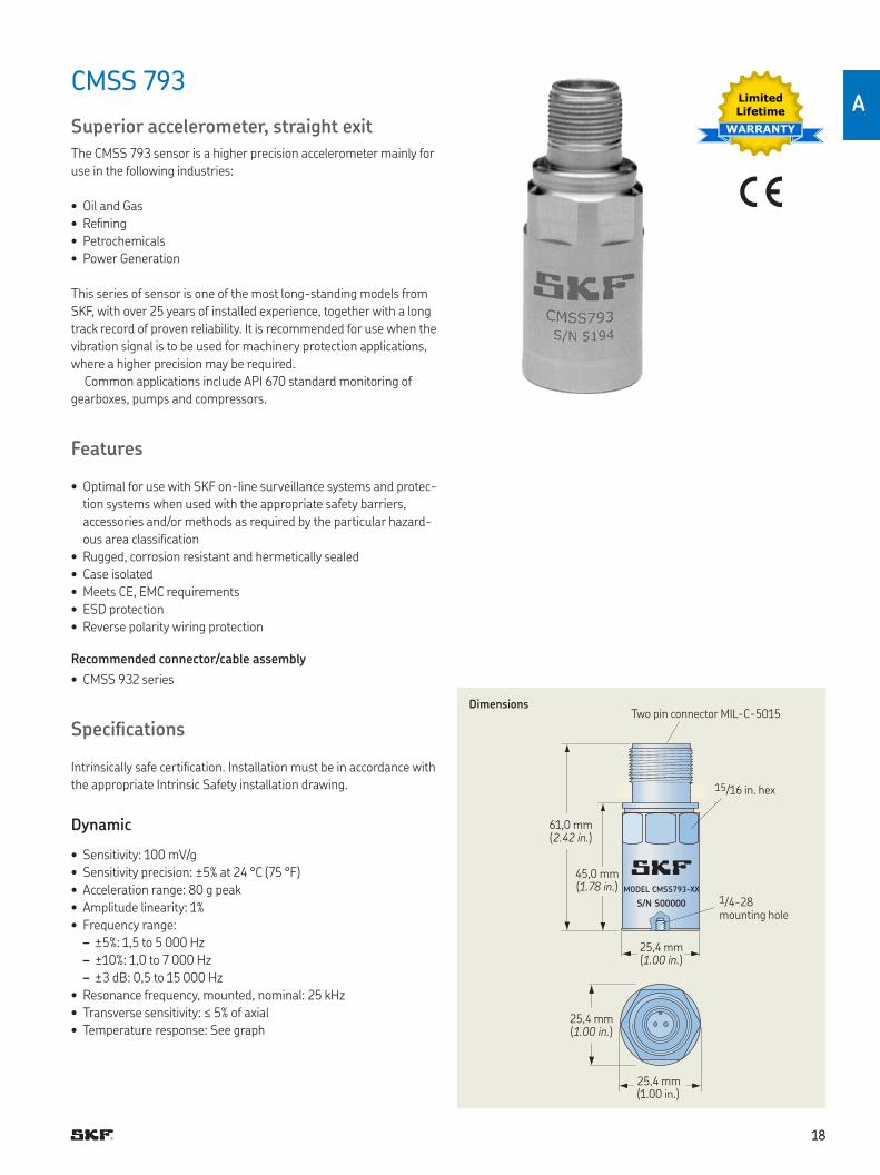
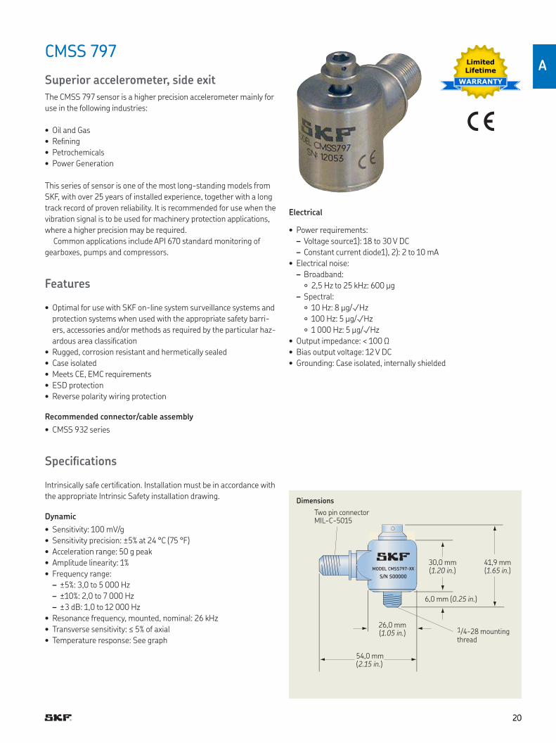
CMSS 793
Superior accelerometer, straight exit
The CMSS 793 sensor is a higher precision accelerometer mainly for
use in the following industries:
• Oil and Gas
• Reining
• Petrochemicals
• Power Generation
This series of sensor is one of the most long-standing models from
SKF, with over 25 years of installed experience, together with a long
track record of proven reliability It is recommended for use when the
vibration signal is to be used for machinery protection applications,
where a higher precision may be required
Common applications include API 670 standard monitoring of
gearboxes, pumps and compressors
Features
• Optimal for use with SKF on-line surveillance systems and protec-
tion systems when used with the appropriate safety barriers,
accessories and/or methods as required by the particular hazard-
ous area classiication
• Rugged, corrosion resistant and hermetically sealed
• Case isolated
• Meets CE, EMC requirements
• ESD protection
• Reverse polarity wiring protection
Recommended connector/cable assembly
• CMSS 932 series
Speciications
Intrinsically safe certiication Installation must be in accordance with
the appropriate Intrinsic Safety installation drawing
Dynamic
• Sensitivity: 100 mV/g
• Sensitivity precision: ±5% at 24 °C (75 °F)
• Acceleration range: 80 g peak
• Amplitude linearity: 1%
• Frequency range:
– ±5%: 1,5 to 5 000 Hz
– ±10%: 1,0 to 7 000 Hz
– ±3 dB: 0,5 to 15 000 Hz
• Resonance frequency, mounted, nominal: 25 kHz
• Transverse sensitivity: ≤ 5% of axial
• Temperature response: See graph
Limited
Lifetime
WARRANTY
MODEL CMSS793-XX
S/N S00000
DimensionsTwo pin connector MIL-C-5015
61,0 mm(2.42 in.)
45,0 mm(1.78 in.)
25,4 mm(1.00 in.)
25,4 mm (1.00 in.)
25,4 mm (1 00 in )
15/16 in hex
1/4-28 mounting hole
1919
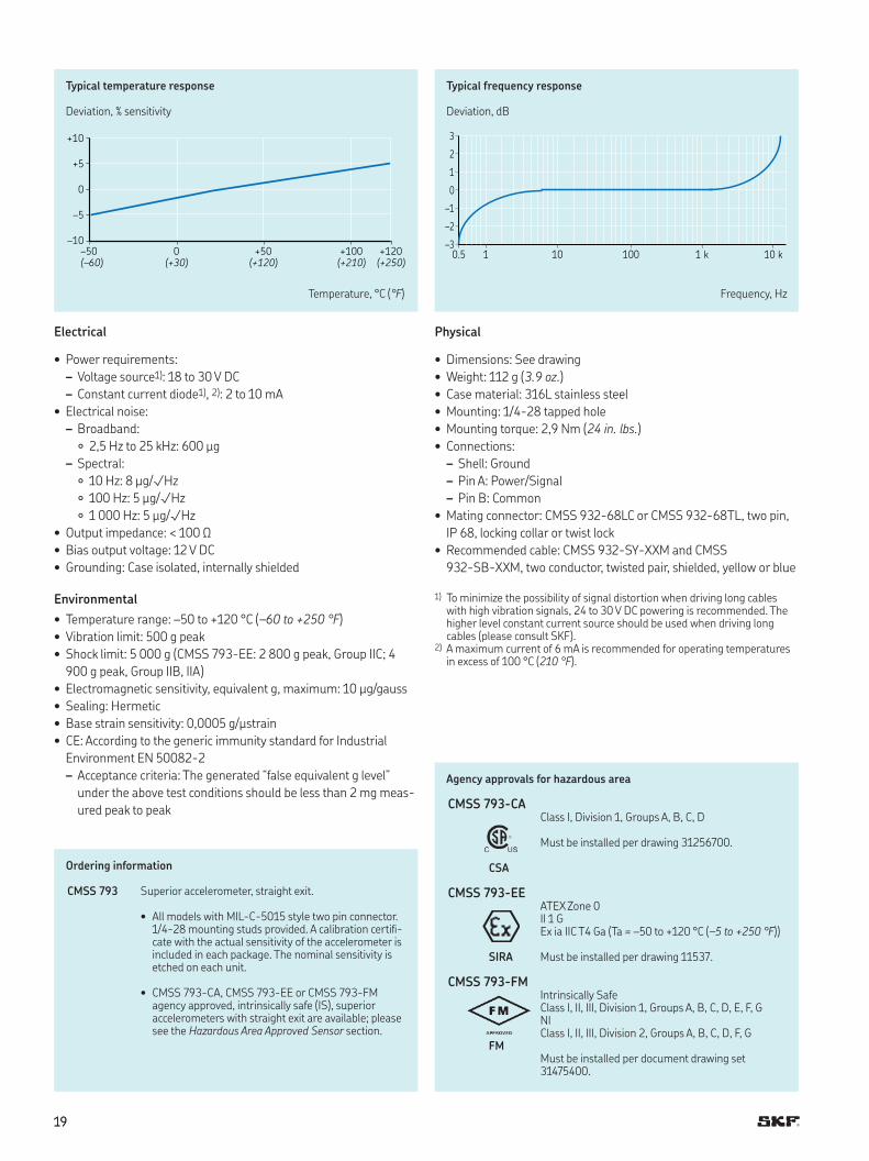
+10
+5
0
–5
–10
–50 0 +50 +100 +120
(–60) (+30) (+120) (+210) (+250)
Typical temperature response
Deviation, % sensitivity
3
2
1
0
–1
–2
–30.5 1 10 100 1 k 10 k
Typical frequency response
Deviation, dB
Temperature, °C (°F) Frequency, Hz
Electrical
• Power requirements:
– Voltage source1): 18 to 30 V DC
– Constant current diode1), 2): 2 to 10 mA
• Electrical noise:
– Broadband:
2,5 Hz to 25 kHz: 600 µg
– Spectral:
10 Hz: 8 µg/√Hz
100 Hz: 5 µg/√Hz
1 000 Hz: 5 µg/√Hz
• Output impedance: < 100 Ω
• Bias output voltage: 12 V DC
• Grounding: Case isolated, internally shielded
Environmental
• Temperature range: –50 to +120 °C (–60 to +250 °F)
• Vibration limit: 500 g peak
• Shock limit: 5 000 g (CMSS 793-EE: 2 800 g peak, Group IIC; 4
900 g peak, Group IIB, IIA)
• Electromagnetic sensitivity, equivalent g, maximum: 10 µg/gauss
• Sealing: Hermetic
• Base strain sensitivity: 0,0005 g/µstrain
• CE: According to the generic immunity standard for Industrial
Environment EN 50082-2
– Acceptance criteria: The generated “false equivalent g level”
under the above test conditions should be less than 2 mg meas-
ured peak to peak
Physical
• Dimensions: See drawing
• Weight: 112 g (3.9 oz.)
• Case material: 316L stainless steel
• Mounting: 1/4-28 tapped hole
• Mounting torque: 2,9 Nm (24 in. lbs.)
• Connections:
– Shell: Ground
– Pin A: Power/Signal
– Pin B: Common
• Mating connector: CMSS 932-68LC or CMSS 932-68TL, two pin,
IP 68, locking collar or twist lock
• Recommended cable: CMSS 932-SY-XXM and CMSS
932-SB-XXM, two conductor, twisted pair, shielded, yellow or blue
1) To minimize the possibility of signal distortion when driving long cables with high vibration signals, 24 to 30 V DC powering is recommended The higher level constant current source should be used when driving long cables (please consult SKF)
2) A maximum current of 6 mA is recommended for operating temperatures in excess of 100 °C (210 °F)
Ordering information
CMSS 793 Superior accelerometer, straight exit
• All models with MIL-C-5015 style two pin connector 1/4-28 mounting studs provided A calibration certii-cate with the actual sensitivity of the accelerometer is included in each package The nominal sensitivity is etched on each unit
• CMSS 793-CA, CMSS 793-EE or CMSS 793-FM agency approved, intrinsically safe (IS), superior accelerometers with straight exit are available; please see the Hazardous Area Approved Sensor section
Agency approvals for hazardous area
CMSS 793-CAClass I, Division 1, Groups A, B, C, D
Must be installed per drawing 31256700
CSA
CMSS 793-EEATEX Zone 0II 1 GEx ia IIC T4 Ga (Ta = –50 to +120 °C (–5 to +250 °F))
SIRA Must be installed per drawing 11537
CMSS 793-FMIntrinsically SafeClass I, II, III, Division 1, Groups A, B, C, D, E, F, GNIClass I, II, III, Division 2, Groups A, B, C, D, F, G
FMMust be installed per document drawing set31475400
2020
A
CMSS 797
Superior accelerometer, side exit
The CMSS 797 sensor is a higher precision accelerometer mainly for
use in the following industries:
• Oil and Gas
• Reining
• Petrochemicals
• Power Generation
This series of sensor is one of the most long-standing models from
SKF, with over 25 years of installed experience, together with a long
track record of proven reliability It is recommended for use when the
vibration signal is to be used for machinery protection applications,
where a higher precision may be required
Common applications include API 670 standard monitoring of
gearboxes, pumps and compressors
Features
• Optimal for use with SKF on-line system surveillance systems and
protection systems when used with the appropriate safety barri-
ers, accessories and/or methods as required by the particular haz-
ardous area classiication
• Rugged, corrosion resistant and hermetically sealed
• Case isolated
• Meets CE, EMC requirements
• ESD protection
• Reverse polarity wiring protection
Recommended connector/cable assembly
• CMSS 932 series
Speciications
Intrinsically safe certiication Installation must be in accordance with
the appropriate Intrinsic Safety installation drawing
Dynamic
• Sensitivity: 100 mV/g
• Sensitivity precision: ±5% at 24 °C (75 °F)
• Acceleration range: 50 g peak
• Amplitude linearity: 1%
• Frequency range:
– ±5%: 3,0 to 5 000 Hz
– ±10%: 2,0 to 7 000 Hz
– ±3 dB: 1,0 to 12 000 Hz
• Resonance frequency, mounted, nominal: 26 kHz
• Transverse sensitivity: ≤ 5% of axial
• Temperature response: See graph
Limited
Lifetime
WARRANTY
MODEL CMSS797-XX
S/N S00000
Dimensions
Two pin connector MIL-C-5015
30,0 mm(1.20 in.)
41,9 mm(1.65 in.)
26,0 mm(1.05 in.)
6,0 mm (0.25 in.)
54,0 mm (2.15 in.)
1/4-28 mounting thread
Electrical
• Power requirements:
– Voltage source1): 18 to 30 V DC
– Constant current diode1), 2): 2 to 10 mA
• Electrical noise:
– Broadband:
2,5 Hz to 25 kHz: 600 µg
– Spectral:
10 Hz: 8 µg/√Hz
100 Hz: 5 µg/√Hz
1 000 Hz: 5 µg/√Hz
• Output impedance: < 100 Ω
• Bias output voltage: 12 V DC
• Grounding: Case isolated, internally shielded
2121
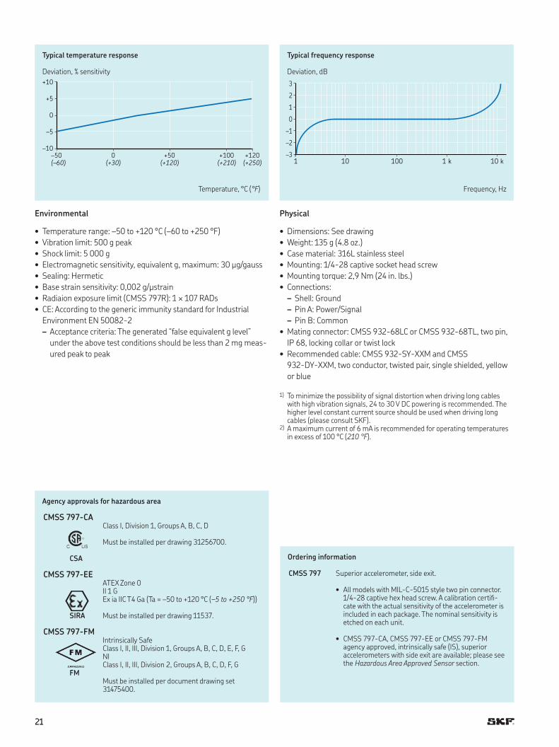
+10
+5
0
–5
–10
–50 0 +50 +100 +120
(–60) (+30) (+120) (+210) (+250)
Typical temperature response
Deviation, % sensitivity
3
2
1
0
–1
–2
–31 10 100 1 k 10 k
Typical frequency response
Deviation, dB
Temperature, °C (°F) Frequency, Hz
Environmental
• Temperature range: –50 to +120 °C (–60 to +250 °F)
• Vibration limit: 500 g peak
• Shock limit: 5 000 g
• Electromagnetic sensitivity, equivalent g, maximum: 30 µg/gauss
• Sealing: Hermetic
• Base strain sensitivity: 0,002 g/µstrain
• Radiaion exposure limit (CMSS 797R): 1 × 10⁷ RADs
• CE: According to the generic immunity standard for Industrial
Environment EN 50082-2
– Acceptance criteria: The generated “false equivalent g level”
under the above test conditions should be less than 2 mg meas-
ured peak to peak
Physical
• Dimensions: See drawing
• Weight: 135 g (4 8 oz )
• Case material: 316L stainless steel
• Mounting: 1/4-28 captive socket head screw
• Mounting torque: 2,9 Nm (24 in lbs )
• Connections:
– Shell: Ground
– Pin A: Power/Signal
– Pin B: Common
• Mating connector: CMSS 932-68LC or CMSS 932-68TL, two pin,
IP 68, locking collar or twist lock
• Recommended cable: CMSS 932-SY-XXM and CMSS
932-DY-XXM, two conductor, twisted pair, single shielded, yellow
or blue
1) To minimize the possibility of signal distortion when driving long cables with high vibration signals, 24 to 30 V DC powering is recommended The higher level constant current source should be used when driving long cables (please consult SKF)
2) A maximum current of 6 mA is recommended for operating temperatures in excess of 100 °C (210 °F)
Agency approvals for hazardous area
CMSS 797-CAClass I, Division 1, Groups A, B, C, D
Must be installed per drawing 31256700
CSA
CMSS 797-EEATEX Zone 0II 1 GEx ia IIC T4 Ga (Ta = –50 to +120 °C (–5 to +250 °F))
SIRA Must be installed per drawing 11537
CMSS 797-FMIntrinsically SafeClass I, II, III, Division 1, Groups A, B, C, D, E, F, GNIClass I, II, III, Division 2, Groups A, B, C, D, F, G
FMMust be installed per document drawing set31475400
Ordering information
CMSS 797 Superior accelerometer, side exit
• All models with MIL-C-5015 style two pin connector 1/4-28 captive hex head screw A calibration certii-cate with the actual sensitivity of the accelerometer is included in each package The nominal sensitivity is etched on each unit
• CMSS 797-CA, CMSS 797-EE or CMSS 797-FM agency approved, intrinsically safe (IS), superior accelerometers with side exit are available; please see the Hazardous Area Approved Sensor section
2222
A
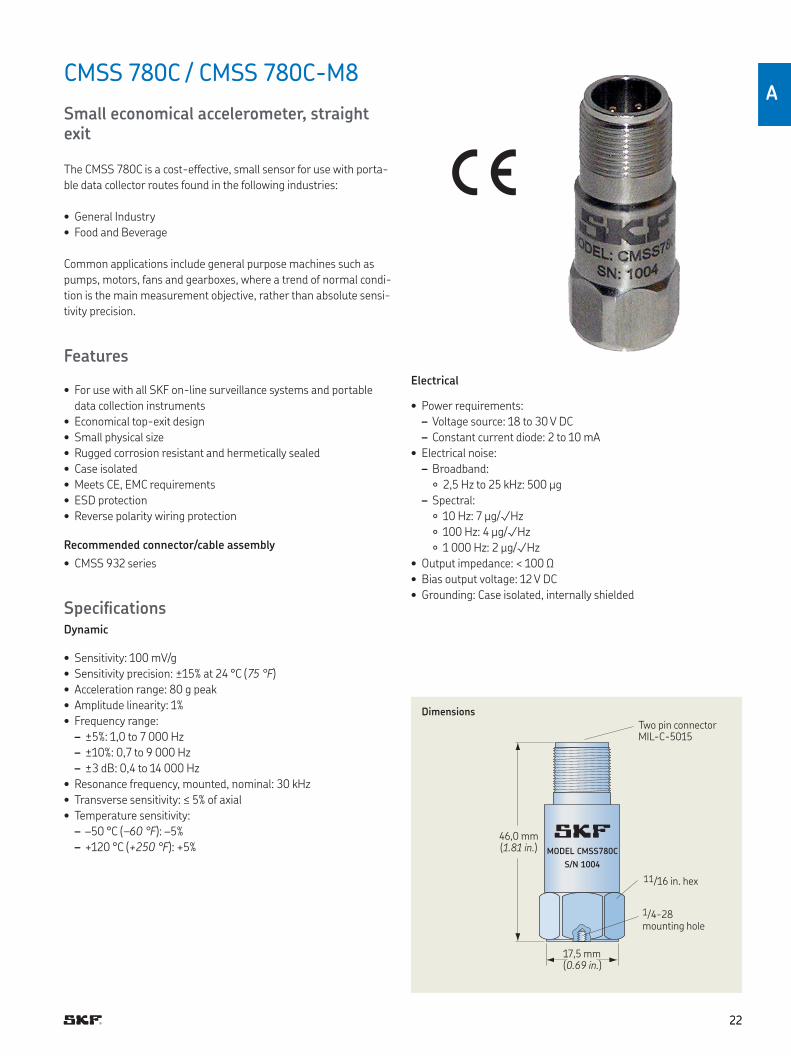
CMSS 780C / CMSS 780C-M8
Small economical accelerometer, straight exit
The CMSS 780C is a cost-effective, small sensor for use with porta-
ble data collector routes found in the following industries:
• General Industry
• Food and Beverage
Common applications include general purpose machines such as
pumps, motors, fans and gearboxes, where a trend of normal condi-
tion is the main measurement objective, rather than absolute sensi-
tivity precision
Features
• For use with all SKF on-line surveillance systems and portable
data collection instruments
• Economical top-exit design
• Small physical size
• Rugged corrosion resistant and hermetically sealed
• Case isolated
• Meets CE, EMC requirements
• ESD protection
• Reverse polarity wiring protection
Recommended connector/cable assembly
• CMSS 932 series
SpeciicationsDynamic
• Sensitivity: 100 mV/g
• Sensitivity precision: ±15% at 24 °C (75 °F)
• Acceleration range: 80 g peak
• Amplitude linearity: 1%
• Frequency range:
– ±5%: 1,0 to 7 000 Hz
– ±10%: 0,7 to 9 000 Hz
– ±3 dB: 0,4 to 14 000 Hz
• Resonance frequency, mounted, nominal: 30 kHz
• Transverse sensitivity: ≤ 5% of axial
• Temperature sensitivity:
– –50 °C (–60 °F): –5%
– +120 °C (+250 °F): +5% MODEL CMSS780C
S/N 1004
DimensionsTwo pin connector MIL-C-5015
46,0 mm(1.81 in.)
17,5 mm (0.69 in.)
11/16 in hex
1/4-28 mounting hole
Electrical
• Power requirements:
– Voltage source: 18 to 30 V DC
– Constant current diode: 2 to 10 mA
• Electrical noise:
– Broadband:
2,5 Hz to 25 kHz: 500 µg
– Spectral:
10 Hz: 7 µg/√Hz
100 Hz: 4 µg/√Hz
1 000 Hz: 2 µg/√Hz
• Output impedance: < 100 Ω
• Bias output voltage: 12 V DC
• Grounding: Case isolated, internally shielded
2323
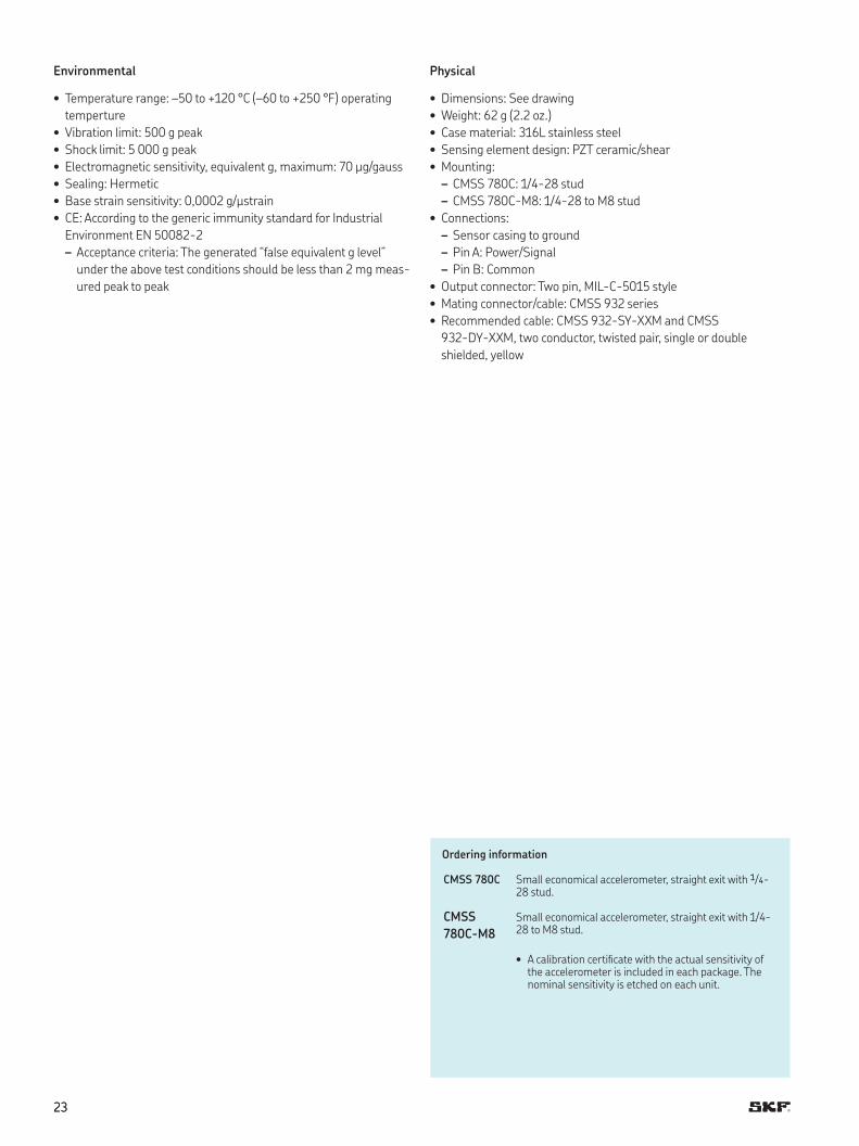
Environmental
• Temperature range: –50 to +120 °C (–60 to +250 °F) operating
temperture
• Vibration limit: 500 g peak
• Shock limit: 5 000 g peak
• Electromagnetic sensitivity, equivalent g, maximum: 70 µg/gauss
• Sealing: Hermetic
• Base strain sensitivity: 0,0002 g/µstrain
• CE: According to the generic immunity standard for Industrial
Environment EN 50082-2
– Acceptance criteria: The generated “false equivalent g level”
under the above test conditions should be less than 2 mg meas-
ured peak to peak
Physical
• Dimensions: See drawing
• Weight: 62 g (2 2 oz )
• Case material: 316L stainless steel
• Sensing element design: PZT ceramic/shear
• Mounting:
– CMSS 780C: 1/4-28 stud
– CMSS 780C-M8: 1/4-28 to M8 stud
• Connections:
– Sensor casing to ground
– Pin A: Power/Signal
– Pin B: Common
• Output connector: Two pin, MIL-C-5015 style
• Mating connector/cable: CMSS 932 series
• Recommended cable: CMSS 932-SY-XXM and CMSS
932-DY-XXM, two conductor, twisted pair, single or double
shielded, yellow
Ordering information
CMSS 780C Small economical accelerometer, straight exit with 1/4-28 stud
CMSS
780C-M8
Small economical accelerometer, straight exit with 1/4-28 to M8 stud
• A calibration certiicate with the actual sensitivity of the accelerometer is included in each package The nominal sensitivity is etched on each unit
2424
A
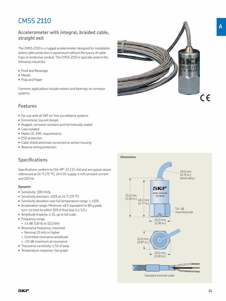
CMSS 2110
Accelerometer with integral, braided cable, straight exit
The CMSS 2110 is a rugged accelerometer designed for installation
where cable protection is paramount without the luxury of cable
trays or protective conduit The CMSS 2110 is typically used in the
following industries:
• Food and Beverage
• Metals
• Pulp and Paper
Common applications include motors and bearings on conveyor
systems
Features
• For use with all SKF on-line surveillance systems
• Economical, top exit design
• Rugged, corrosion resistant and hermetically sealed
• Case isolated
• Meets CE, EMC requirements
• ESD protection
• Cable shield and braid connected to sensor housing
• Reverse wiring protection
Speciications
Speciications conform to ISA-RP-37 2 (1-64) and are typical values
referenced at 24 °C (75 °F), 24 V DC supply, 4 mA constant current
and 100 Hz
Dynamic
• Sensitivity: 100 mV/g
• Sensitivity precision: ±10% at 24 °C (75 °F)
• Sensitivity deviation over full temperature range: ≤ ±10%
• Acceleration range: Minimum ±8 V equivalent to 80 g peak;
turn-on time to within 10% of inal bias is ≤ 1,0 s
• Amplitude linearity: ≤ 1%, up to full scale
• Frequency range:
– ±3 dB: 0,8 Hz to 10,0 kHz
• Resonance frequency, mounted:
– Nominal 25 kHz or higher
– Controlled resonance amplitude
– +15 dB maximum at resonance
• Transverse sensitivity: ≤ 5% of axial
• Temperature response: See graph
MODEL CMSS2110
S/N 98765
Dimensions
Standard armored cable
51,0 mm(2.00 in.) 45,0 mm
(1.77 in.)
25,0 mm(1.00 in.)
22,0 mm(0.87 in.)
19,0 mm(0.75 in.)bend radius
25,0 mm (1.00 in.)
1/4-28 mounting hole
2525
+10
+5
0
–5
–10
–50 0 +50 +100 +120
(–60) (+30) (+120) (+210) (+250)
Typical temperature response
Deviation, % sensitivity
+20
0
–20 1 10 100 1k 10k 100k
+10
–10
Typical frequency response
Deviation, dB
Temperature, °C (°F) Frequency, Hz
Electrical
• Power requirements:
– Voltage source: 24 V DC nominal, ±20%
– Constant current diode: 2 to 10 mA, recommend 4 mA
• Electrical noise:
– Broadband (2,5 Hz to 25,0 kHz): < 0,6 mg RMS
• Output impedance: < 50 Ω
• Bias output voltage:
– 12,5 to 13,5 V DC for 24 V DC supply over temperature range –50
to +100 °C (–60 to +210 °F)
– 11,0 to 14,0 V DC for 24 V DC supply over temperature range 100
to 120 °C (210 to 250 °F)
• Grounding:
– Case isolated, internally shielded (Faraday cage)
– The internal Faraday cage is connected to the signal return of
the shielded twisted pair
– The internal shield, as well as the stainless steel braid, is con-
nected to the sensor housing
• Isolation to sensor housing: > 10 MΩ over full temperature range
• Over-voltage protection
• Reverse polarity (wiring) protection
Environmental
• Temperature range: –50 to +120 °C (–60 to +250 °F) operating
temperature
• Vibration limit: 500 g peak
• Shock limit: 1 000 g peak
• Electromagnetic sensitivity, equivalent g, maximum: < 100 µg/
gauss at 50 to 60 Hz
• Base strain sensitivity: 200 µg/µstrain
• CE: According to the generic immunity standard for Industrial
Environment EN 50082-2
– Acceptance criteria: The generated “false equivalent g level”
under the above test conditions should be less than 2 mg meas-
ured peak to peak
Physical
• Dimensions: See drawing
• Cable length: 5 m (16.4 ft.)
• Weight: 350 g (12.4 oz.), including cable
• Case material: 316L stainless steel
• Mounting:
– Internal 1/4-28 thread
– M8 × 1,25 and 1/4-28 to 1/4-28 mounting studs provided
• Mounting torque: 2,9 Nm (24 in. lbs.)
• Connections:
– Power signal: White
– Common: Black
– Shielding: Drain
• Cable:
– Integral cable, 5 m (16.4 ft.) long
– Shielded twisted pair; two times AWG 20
– Shield grounded to sensor housing
– Cable armored with 304 stainless steel braid
– Braid also connected to sensor housing
– High temperature cable
– Cable diameter less than 5 mm (0.19 in.)
• Cable speciications: 2/C 20 AWG FEP/A/M/FEP 10-1254; recom-
mend two wire, twisted, shielded
Ordering information
CMSS 2110 Accelerometer with 5 meter (16,4 ft) overbraided inte-gral cable, straight exit
CMSS
2110-33
Accelerometer with 10 meter (33 ft) integral braided cable, straight exit
• 1/4-28 and M8 mounting studs provided Calibration sensitivity is provided for each accelerometer package with nominal sensitivity etched on each unit
2626
A
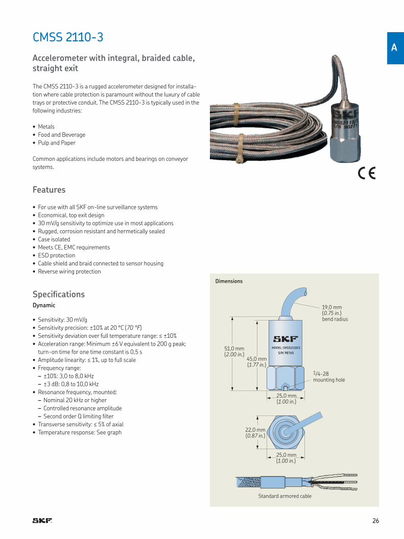
CMSS 2110-3
Accelerometer with integral, braided cable, straight exit
The CMSS 2110-3 is a rugged accelerometer designed for installa-
tion where cable protection is paramount without the luxury of cable
trays or protective conduit The CMSS 2110-3 is typically used in the
following industries:
• Metals
• Food and Beverage
• Pulp and Paper
Common applications include motors and bearings on conveyor
systems
Features
• For use with all SKF on-line surveillance systems
• Economical, top exit design
• 30 mV/g sensitivity to optimize use in most applications
• Rugged, corrosion resistant and hermetically sealed
• Case isolated
• Meets CE, EMC requirements
• ESD protection
• Cable shield and braid connected to sensor housing
• Reverse wiring protection
SpeciicationsDynamic
• Sensitivity: 30 mV/g
• Sensitivity precision: ±10% at 20 °C (70 °F)
• Sensitivity deviation over full temperature range: ≤ ±10%
• Acceleration range: Minimum ±6 V equivalent to 200 g peak;
turn-on time for one time constant is 0,5 s
• Amplitude linearity: ≤ 1%, up to full scale
• Frequency range:
– ±10%: 3,0 to 8,0 kHz
– ±3 dB: 0,8 to 10,0 kHz
• Resonance frequency, mounted:
– Nominal 20 kHz or higher
– Controlled resonance amplitude
– Second order Q limiting ilter
• Transverse sensitivity: ≤ 5% of axial
• Temperature response: See graph
MODEL CMSS2110/3
S/N 98765
Dimensions
Standard armored cable
51,0 mm(2.00 in.)
45,0 mm(1.77 in.)
25,0 mm(1.00 in.)
22,0 mm(0.87 in.)
19,0 mm(0.75 in.)bend radius
25,0 mm (1.00 in.)
1/4-28 mounting hole

Typical temperature response
Deviation, % sensitivity
Typical frequency response
Deviation [dB]
Temperature, °C (°F) Frequency [Hz]
+10
+5
0
–5
–10
–50 0 +50 +100 +120
(–60) (+30) (+120) (+210) (+250)
+20
0
–20 1 10 100 1k 10k 100k
+10
–10
Electrical
• Power requirements:
– Voltage source: 24 V DC, ±20%
– Constant current diode: 2 to 6 mA
• Electrical noise:
– Broadband (2,0 to 20,0 kHz): < 0,7 mg RMS
• Output impedance: < 50 Ω
• Bias output voltage: 11,5 V DC ( ±10%) for 24 V DC supply voltage
over the temperature range from –50 to +100 °C (–60 to +210 °F)
• Grounding:
– Case isolated, internally shielded (Faraday cage)
– The internal Faraday cage is connected to the signal return of
the shielded twisted pair
– The internal shield, as well as the stainless steel braid, is con-
nected to the sensor housing
• Isolation to sensor housing: > 10 MΩ over full temperature range
• Over-voltage protection
• Reverse polarity (wiring) protection
Environmental
• Temperature range: –50 to +120 °C (–60 to +250 °F) operating
temperature
• Vibration limit: 500 g peak
• Shock limit: 1 000 g peak
• Electromagnetic sensitivity, equivalent g, maximum:
< 100 µg/gauss at 50 to 60 Hz
• Base strain sensitivity: 200 µg/µstrain
• CE: According to the generic immunity standard for Industrial
Environment EN 50082-2
– Acceptance criteria: The generated “false equivalent g level”
under the above test conditions should be less than 2 mg meas-
ured peak to peak
Physical
• Dimensions: See drawing
• Cable length: 5 m (16.4 ft.)
• Weight: 350 g (12.3 oz.), including cable
• Case material: 316L stainless steel
• Mounting: 1/4-28 to M8 and 1/4-28 to 1/4-28 mounting studs
provided
• Mounting torque: 2,9 Nm (24 in- lbs.)
• Connections:
– Integral cable
– Power/Signal: White
– Common: Black
– Shielding: Drain
• Cable:
– Integral cable, 5 m (16.4 ft.) long
– Shielded twisted pair; two times AWG 20
– Shield grounded to sensor housing
– Cable armored with 304 stainless steel braid
– Braid also connected to sensor housing
– High temperature cable
– Cable diameter less than 5 mm (0.19 in.)
• Cable speciications: 2/C 20 AWG FEP/A/M/FEP 10-1254
• Cable capacitance: 25 pF/m (80 pF/ft.)
Ordering information
CMSS 2110-3 Accelerometer, 30mV/g, with 5 meter (16.4 ft) integral braided cable, straight exit
• 1/4-28 and M8 mounting studs provid Calibration sensitivity is provided for each accelerometer package with nominal sensitivity etched on each unit
2727
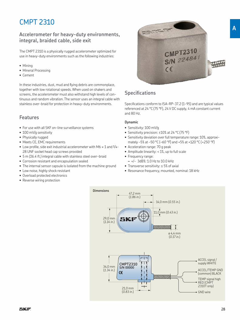
CMPT 2310
Accelerometer for heavy-duty environments, integral, braided cable, side exit
The CMPT 2310 is a physically rugged accelerometer optimized for
use in heavy-duty environments such as the following industries:
• Mining
• Mineral Processing
• Cement
In these industries, dust, mud and lying debris are commonplace,
together with low rotational speeds When used on shakers and
screens, the accelerometer must also withstand high levels of con-
tinuous and random vibration The sensor uses an integral cable with
stainless over-braid for protection in heavy-duty environments
Features
• For use with all SKF on-line surveillance systems
• 100 mV/g sensitivity
• Physically rugged
• Meets CE, EMC requirements
• Low proile, side exit industrial accelerometer with M6 × 1 and 1/4-
28 UNF socket head cap screws provided
• 5 m (16.4 ft.) integral cable with stainless steel over-braid
• Corrosion resistant and encapsulation sealed
• The internal sensor capsule is isolated from the machine ground
• Low noise, highly shock resistant
• Overload protected electronics
• Reverse wiring protection
Speciications
Speciications conform to ISA-RP-37 2 (1-95) and are typical values
referenced at 24 °C (75 °F), 24 V DC supply, 4 mA constant current
and 80 Hz
Dynamic
• Sensitivity: 100 mV/g
• Sensitivity precision: ±10% at 24 °C (75 °F)
• Sensitivity deviation over full temperature range: 10%, approxi-
mately –5% at –50 °C (–60 °F) and +5% at +120 °C (+250 °F)
• Acceleration range: 70 g peak
• Amplitude linearity: < 1%, up to full scale
• Frequency range:
– +/- 3dB%: 1 0 Hz to 10 0 kHz
• Transverse sensitivity: ≤ 5% of axial
• Resonance frequency, mounted, nominal: 18 kHz
2828
A
CMPT2310S/N 00000
Dimensions
ACCEL signal / supply WHITE
ACCEL/TEMP GND (common) BLACK
TEMP signal high RED (CMPT 2310T only)
GND wire
47,2 mm(1.86 in.)
21,0 mm(0.83 in.)
ø 4,4 mm(0.17 in.)
29,0 mm(1.14 in.)
34,0 mm(1.34 in.)
14,0 mm (0.55 in.)
11,0 mm (0.43 in.)

2929
Electrical
• Power requirements:
– Voltage source: 24 V DC nominal, 18 to 30 V DC
– Constant current diode: 4 mA at 24 V, 2 to 10 mA is permissible
• Electrical noise: < 1 mg RMS broadband 2,5 Hz to 25,0 kHz
• Bias output voltage: 11,5 V DC, ±10% for 24 V DC supply at
25 °C (77°F)
• Grounding: Case isolated, internally shielded (Faraday cage)
– Faraday cage connected to power supply return
• Over-voltage protection: Approximately 18 V DC
• Reverse polarity (wiring) protection
Environmental
• Temperature range:
– Accelerometer measurement temperature range:
–50 to +120 °C (–60 to +250 °F)
– Maximum operating temperature: 120 °C (250 °F)
– Storage temperature: –50 to +150 °C (–60 to +300 °F)
• Vibration limit: 70 g peak
• Shock limit: 5 000 g peak
• Electromagnetic sensitivity, equivalent g, maximum: < 100 µg/
gauss at 50 to 60 Hz
• CE: According to the generic immunity standard for Industrial
Environment EN 50082-2
– Acceptance criteria: The generated “false equivalent g level”
under the above test conditions should be less than 2 mg meas-
ured peak to peak
• IEC: 529, IP 67 (For climatic conditions, recommend to use conduit/
hose over braided cable )
Physical
• Dimensions: See drawing
• Weight:
– Sensor without cable: 210 g (7.4 oz.)
– Sensor with cable: 410 g (14.5 oz.)
• Case material: 304 stainless steel
• Mounting: M6 × 1 and 1/4-28 UNF socket head cap screws
provided
• Mounting torque: 6 Nm (50 in. lbs.)
• Cable: Integral cable, 5 m (16.4 ft.) length
• Wire speciication: 0,32 mm2 (AWG 22) stranded tin copper
(seven strands at 0,05 mm2 each)
• Connections:
– White: ACCEL signal/power (connected to constant current
source)
– Black: ACCEL signal ground (GND)
– Blank twisted wire: Screen connected to internal shield
Ordering information
CMPT 2310 Accelerometer with 5 meter (16,4 ft) integral braided cable, side exit
CMPT 2310X10
Accelerometer with 10 meter (33 ft) integral braided cable, side exit
CMPT 2310X15
Accelerometer with 15 meter (50 ft) integral braided cable, side exit
• 1/4-28 and M6 × 1 socket head cap screws provided. Calibration certiicate with the actual sensitivity is provided for each accelerometer package.
3030
A
CMPT 2323
Accelerometer for heavy-duty environments, integral, braided cable, side exit
The CMPT 2323 is a physically rugged accelerometer optimized for
use in heavy-duty environments such as the following industries:
• Mining
• Mineral Processing
• Cement
In these industries, dust, mud and lying debris are commonplace,
together with low rotational speeds When used on shakers and
screens, the accelerometer must also withstand high levels of con-
tinuous and random vibration The sensor uses an integral cable with
stainless over-braid for protection in heavy-duty environments A
higher sensitivity is used for detection of low amplitude signals in
slow moving equipment
Features
• For use with all SKF on-line surveillance systems
• 230 mV/g sensitivity
• Physically rugged
• Meets CE, EMC requirements
• Low proile, side exit industrial accelerometer with M6 × 1 and
1/4-28 UNF socket head cap screws provided
• 5 m (16.4 ft.) integral cable with stainless steel over-braid
• Corrosion resistant and encapsulation sealed
• The internal sensor capsule is isolated from the machine ground
• Low noise, highly shock resistant
• Overload protected electronics
• Reverse wiring protection
Speciications
Speciications conform to ISA-RP-37 2 (1-95) and are typical values
referenced at 24 °C (75 °F), 24 V DC supply, 4 mA constant current
and 80 Hz
Dynamic
• Sensitivity: 230 mV/g
• Sensitivity precision: ±10% at 24 °C (75 °F)
• Sensitivity deviation over full temperature range: 10%, approxi-
mately –5% at –50 °C (–60 °F) and +5% at +120 °C (+250 °F)
• Acceleration range: 70 g peak
• Amplitude linearity: < 1%, up to full scale
• Frequency range:
– +/- 3dB: 0 2 Hz to 10 0kHz
• Transverse sensitivity: ≤ 5% of axial
• Resonance frequency, mounted, nominal: 18 kHz
CMPT2323S/N 00000
Dimensions
ACCEL signal / supply WHITE
ACCEL/TEMP GND (common) BLACK
TEMP signal high RED (CMPT 2323T only)
GND wire
47,2 mm(1.86 in.)
21,0 mm(0.83 in.)
ø 4,4 mm(0.17 in.)
29,0 mm(1.14 in.)
34,0 mm(1.34 in.)
14,0 mm (0.55 in.)
11,0 mm (0.43 in.)

3131
Electrical
• Power requirements:
– Voltage source: 24 V DC nominal, 18 to 30 V DC
– Constant current diode: 4 mA at 24 V, 2 to 10 mA is permissible
• Electrical noise: < 1 mg RMS broadband 2,5 Hz to 25,0 kHz
• Bias output voltage: 11,5 V DC, ±10% for 24 V DC supply at
25 °C (77 °F)
• Grounding: Case isolated, internally shielded (Faraday cage)
– Faraday cage connected to power supply return
• Over-voltage protection: Approximately 18 V DC
• Reverse polarity (wiring) protection
Environmental
• Temperature range:
– Accelerometer measurement temperature range:
–50 to +120 °C (–60 to +250 °F)
– Maximum operating temperature: 120 °C (250 °F)
– Storage temperature: –50 to +150 °C (–60 to +300 °F)
• Vibration limit: 70 g peak
• Shock limit: 5 000 g peak
• Electromagnetic sensitivity, equivalent g, maximum: < 100 µg/
gauss at 50 to 60 Hz
• CE: According to the generic immunity standard for Industrial
Environment EN 50082-2
– Acceptance criteria: The generated “false equivalent g level”
under the above test conditions should be less than 2 mg meas-
ured peak to peak
• IEC: 529, IP 67 (For climatic conditions, recommend to use conduit/
hose over braided cable )
Physical
• Dimensions: See drawing
• Weight:
– Sensor without cable: 210 g (7.4 oz.)
– Sensor with cable: 410 g (14.5 oz.)
• Case material: 304 stainless steel
• Mounting: M6 × 1 and 1/4-28 UNF socket head cap screws
provided
• Mounting torque: 6 Nm (50 in. lbs.)
• Cable: Integral cable, 5 m (16.4 ft.) length
• Wire speciication: 0,32 mm2 (AWG 22) stranded tin copper
(seven strands at 0,05 mm2 each)
• Connections:
– White: ACCEL signal/power (connected to constant current
source)
– Black: ACCEL signal ground (GND)
– Blank twisted wire: Screen connected to internal shield
Ordering information
CMPT 2323 Accelerometer, 230 mV/g, with 5 meter (16,4 ft) integral braided cable, side exit
CMPT 2323X10
Accelerometer, 230 mV/g, with 10 meter (33 ft) integral braided cable, side exit
CMPT 2323X15
Accelerometer, 230 mV/g, with 15 meter (50 ft) integral braided cable, side exit
• 1/4-28 and M6 × 1 socket head cap screws provided. Calibration certiicate with the actual sensitivity is provided for each accelerometer package.
3232
A
CMSS WIND-100-10
Small accelerometer, with integral cable, side exit
The CMSS WIND-100-10 is an compact accelerometer commonly
used in the following applications:
• Wind turbine gearboxes
• Wind turbine generators
The small-size accelerometer is specially conigured for unobtrusive
mounting on wind turbine drive components, within the relatively
protected environment of the turbine’s nacelle An integral cable is
used to eliminate any cause to travel to a remote site to ix a loose
connector
Features
• For use with all SKF on-line surveillance systems
• 100 mV/g sensitivity
• Meets CE, EMC requirements
• High resistance to electrical noise
• Low proile integral cable accelerometer
• Compact design ideal for mounting with limited space
• Corrosion resistant
Speciications
Speciications based on low proile industrial constant current accel-
erometer, 100 mV/g, 0,5 to 10 000 Hz, side exit, 3 m (10 ft.) integral
cable and swiveled base
Dynamic
• Sensitivity: 100 mV/g
• Sensitivity precision: ±15% at 24 °C (75 °F)
• Acceleration range: 50 g peak
• Amplitude linearity: ±1%
• Frequency range: +/- 3dB: 0,5 Hz to 10 kHz (30 to 600 000 cpm)
• Resonance frequency, mounted, nominal: 25 kHz (1 500 kcpm)
• Transverse sensitivity: ≤ 7%
• Temperature response:See graph
40,1(1.58)
24,6(0.97)
1/2-20 UNF-2A
M6 x 1,00-6g
15,9(0.63)
Dimensions
14,0 mm (0.56 in.) hex
1/8 in. hex allen key required
Molded integral cable terminating in blunt cut 3 m (10 ft.) from application
Mounting stud model (supplied)
Red: Signal/Power
Black: GroundShielding: Drain
3
2
1
0
–1
–2
–30.5 1 10 100 1 k 10 k
+20
+10
0
–10
–20
–54 0 +50 +100 +121
(–65) (+30) (+120) (+210) (+250)
Typical temperature response
Deviation, % sensitivity
Typical frequency response
Deviation [dB]
Temperature, °C (° F ) Frequency [Hz]
Electrical
• Power requirements:
– Voltage source: 18 to 28 V DC
– Constant current diode: 2 to 20 mA
• Electrical noise:
– Spectral:
Output impedance: < 150 Ω
• Bias output voltage: 8 to 12 V DC
• Electrical isolation (case): > 108 Ω
Environmental
• Temperature range: –55 to +120 °C (–65 to +250 °F)
• Shock limit: 5 000 g peak
• Sealing: Welded hermetic
• CE: According to the generic immunity standard for Industrial
Environment EN 50082-2
– Acceptance criteria: The generated “false equivalent g level”
under the above test conditions should be less than 2 mg meas-
ured peak to peak
Physical
• Dimensions: See drawing
• Weight: 31 g (1.1 oz.)
• Case material: 316L Stainless steel, with molded integral cable
• Enclosure rating: IP 68
• Sensing element: Ceramic, shear
• Mounting: Threaded stud 1/4-28 male
• Mounting torque:
– Stud: 9,5 to 10,8 Nm (7 to 8 ft. lbs.)
– Hex nut: 2,7 to 6,8 Nm (2 to 5 ft. lbs.)
• Connection: Molded integral cable, side
• Cable type: Integral FEP cable, stainless steel overbraid
Ordering information
CMSS WIND-100-10
Small accelerometer with integral cable, side exit, 10 m (32.8 ft.)
CMSS WIND-100-15
Small accelerometer with integral cable, side exit, 15 m (49.2 ft.)
CMSS WIND-100-20
Small accelerometer with integral cable, side exit, 20 m (65.6 ft.)
Optional accessories
CMSS-WIND-201 Mounting pad, size 20mm AF dia, 10mm height, M6 thread, stainless steel
3333
3434
BAccelerometers with extended temperature range
• CMSS 2106 Extended temperature range accelerometer, straight exit
• CMSS 2207 Extended temperature range accelerometer, side exit
CMSS 2106 CMSS 2207
Limited
Lifetime
WARRANTY
3535
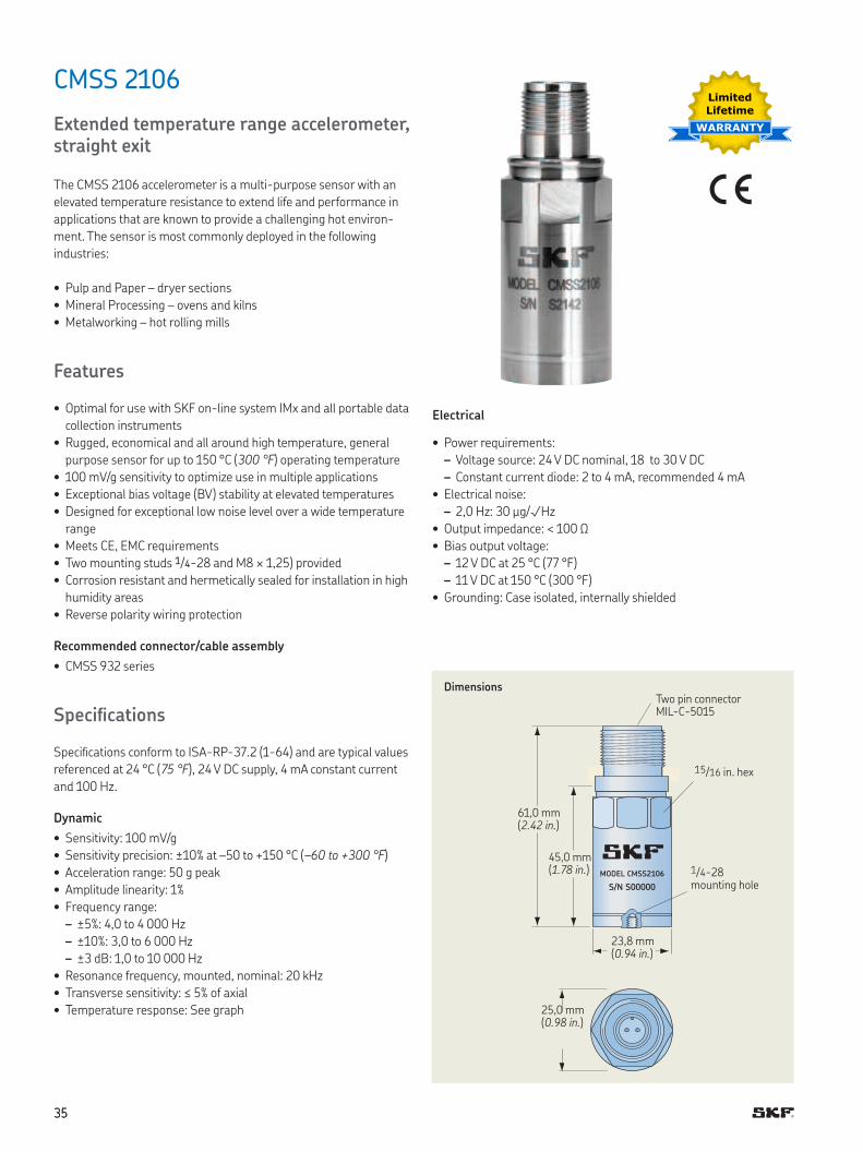
CMSS 2106
Extended temperature range accelerometer, straight exit
The CMSS 2106 accelerometer is a multi-purpose sensor with an
elevated temperature resistance to extend life and performance in
applications that are known to provide a challenging hot environ-
ment The sensor is most commonly deployed in the following
industries:
• Pulp and Paper – dryer sections
• Mineral Processing – ovens and kilns
• Metalworking – hot rolling mills
Features
• Optimal for use with SKF on-line system IMx and all portable data
collection instruments
• Rugged, economical and all around high temperature, general
purpose sensor for up to 150 °C (300 °F) operating temperature
• 100 mV/g sensitivity to optimize use in multiple applications
• Exceptional bias voltage (BV) stability at elevated temperatures
• Designed for exceptional low noise level over a wide temperature
range
• Meets CE, EMC requirements
• Two mounting studs 1/4-28 and M8 × 1,25) provided
• Corrosion resistant and hermetically sealed for installation in high
humidity areas
• Reverse polarity wiring protection
Recommended connector/cable assembly
• CMSS 932 series
Speciications
Speciications conform to ISA-RP-37 2 (1-64) and are typical values
referenced at 24 °C (75 °F), 24 V DC supply, 4 mA constant current
and 100 Hz
Dynamic
• Sensitivity: 100 mV/g
• Sensitivity precision: ±10% at –50 to +150 °C (–60 to +300 °F)
• Acceleration range: 50 g peak
• Amplitude linearity: 1%
• Frequency range:
– ±5%: 4,0 to 4 000 Hz
– ±10%: 3,0 to 6 000 Hz
– ±3 dB: 1,0 to 10 000 Hz
• Resonance frequency, mounted, nominal: 20 kHz
• Transverse sensitivity: ≤ 5% of axial
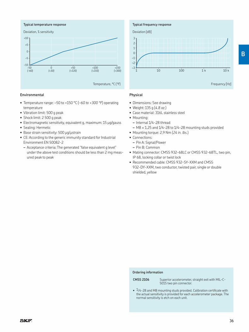
• Temperature response: See graph
Electrical
• Power requirements:
– Voltage source: 24 V DC nominal, 18 to 30 V DC
– Constant current diode: 2 to 4 mA, recommended 4 mA
• Electrical noise:
– 2,0 Hz: 30 µg/√Hz
• Output impedance: < 100 Ω
• Bias output voltage:
– 12 V DC at 25 °C (77 °F)
– 11 V DC at 150 °C (300 °F)
• Grounding: Case isolated, internally shielded
MODEL CMSS2106
S/N S00000
Dimensions
23,8 mm (0.94 in.)
25,0 mm (0.98 in.)
61,0 mm (2.42 in.)
45,0 mm (1.78 in.) 1/4-28
mounting hole
15/16 in hex
Two pin connector MIL-C-5015
3
2
1
0
–1
–2
–31 10 100 1 k 10 k
+10
+5
0
–5
–10
–50 0 +50 +100 +150
(–60) (+30) (+120) (+210) (+300)
Typical temperature response
Deviation, % sensitivity
Typical frequency response
Deviation [dB]
Temperature, °C (°F) Frequency [Hz]
Environmental
• Temperature range: –50 to +150 °C (–60 to +300 °F) operating
temperature
• Vibration limit: 500 g peak
• Shock limit: 2 500 g peak
• Electromagnetic sensitivity, equivalent g, maximum: 15 µg/gauss
• Sealing: Hermetic
• Base strain sensitivity: 500 µg/µstrain
• CE: According to the generic immunity standard for Industrial
Environment EN 50082-2
– Acceptance criteria: The generated “false equivalent g level”
under the above test conditions should be less than 2 mg meas-
ured peak to peak
Physical
• Dimensions: See drawing
• Weight: 135 g (4.8 oz.)
• Case material: 316L stainless steel
• Mounting:
– Internal 1/4-28 thread
– M8 × 1,25 and 1/4-28 to 1/4-28 mounting studs provided
• Mounting torque: 2,9 Nm (24 in. lbs.)
• Connections:
– Pin A: Signal/Power
– Pin B: Common
• Mating connector: CMSS 932-68LC or CMSS 932-68TL, two pin,
IP 68, locking collar or twist lock
• Recommended cable: CMSS 932-SY-XXM and CMSS
932-DY-XXM, two conductor, twisted pair, single or double
shielded, yellow
Ordering information
CMSS 2106 Superior accelerometer, straight exit with MIL-C-5015 two pin connector
• 1/4-28 and M8 mounting studs provided Calibration certiicate with the actual sensitivity is provided for each accelerometer package The normal sensitivity is etch on each unit
3636
B
CMSS 2207
Extended temperature range accelerometer, side exit
The CMSS 2207 accelerometer is a multi-purpose sensor with an
elevated temperature resistance to extend life and performance in
applications that are known to provide a challenging hot environ-
ment The sensor is most commonly deployed in the following
industries:
• Pulp and Paper – dryer sections
• Mineral Processing – ovens and kilns
• Metalworking – hot rolling mills
Features
• Optimal for use with SKF on-line system IMx and all portable data
collection instruments
• Rugged, economical and all around high temperature, general
purpose sensor for up to 150 °C (300 °F) operating temperature
• 100 mV/g sensitivity to optimize use in multiple applications
• Exceptional bias voltage (BV) stability at elevated temperatures
• Designed for exceptional low noise level over a wide temperature
range
• Meets CE, EMC requirements
• Captive mounting bolts (1/4-28 or M6 × 1,0) provided
• Corrosion resistant and hermetically sealed for installation in high
humidity areas
• Reverse polarity wiring protection
Recommended connector/cable assembly
• CMSS 932 series
Speciications
Speciications conform to ISA-RP-37 2 (1-64) and are typical values
referenced at 24 °C (75 °F), 24 V DC supply, 4 mA constant current
and 100 Hz
Dynamic
• Sensitivity: 100 mV/g
• Sensitivity precision: ±10% at 24 °C (75 °F)
• Acceleration range: 50 g peak
• Amplitude linearity: ≤ 1%, up to full scale
• Frequency range:
– ±5%: 4,0 to 5 000 Hz
– ±10%: 3,0 to 7 000 Hz
– ±3 dB: 1,0 to 11 000 Hz
• Resonance frequency, mounted, nominal: 18 5 kHz
• Transverse sensitivity, maximum: ≤ 5% of axial
• Temperature response: See graph
Electrical
• Power requirements:
– Voltage source: 24 V DC nominal, 18 to 30 V DC
– Constant current diode: 2 to 4 mA, recommended 4 mA
• Electrical noise:
• 2,0 Hz: 30 µg/√Hz
• Output impedance: < 100 Ω
• Bias output voltage:
– 12 V DC at 25 °C (77 °F)
– 11 V DC at 150 °C (300 °F)
• Grounding: Case isolated, internally shielded
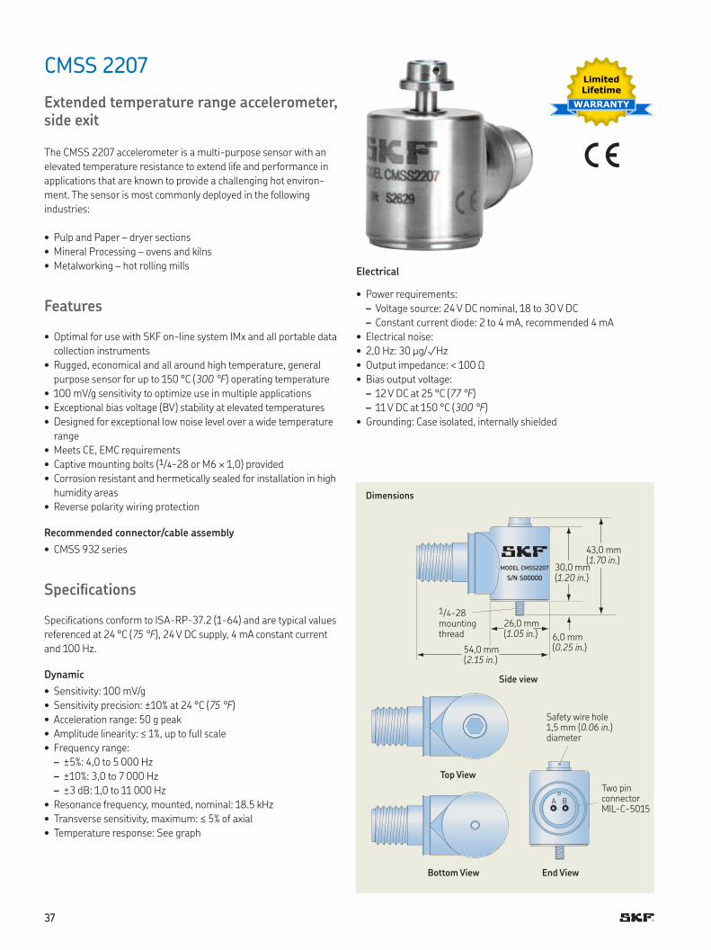
A B
MODEL CMSS2207
S/N S00000
Dimensions
43,0 mm (1.70 in.)
30,0 mm (1.20 in.)
26,0 mm (1.05 in.)
54,0 mm (2.15 in.)
6,0 mm (0.25 in.)
Side view
Top View
Bottom View End View
Safety wire hole 1,5 mm (0.06 in.) diameter
Two pin connector MIL-C-5015
1/4-28 mounting thread
Limited
Lifetime
WARRANTY
3737
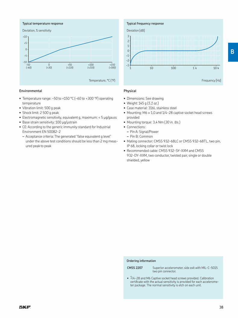
3
2
1
0
–1
–2
–31 10 100 1 k 10 k
+10
+5
0
–5
–10
–50 0 +50 +100 +150
(–60) (+30) (+120) (+210) (+300)
Typical temperature response
Deviation, % sensitivity
Typical frequency response
Deviation [dB]
Temperature, °C (°F) Frequency [Hz]
Environmental
• Temperature range: –50 to +150 °C (–60 to +300 °F) operating
temperature
• Vibration limit: 500 g peak
• Shock limit: 2 500 g peak
• Electromagnetic sensitivity, equivalent g, maximum: < 5 µg/gauss
• Base strain sensitivity: 100 µg/µstrain
• CE: According to the generic immunity standard for Industrial
Environment EN 50082-2
– Acceptance criteria: The generated “false equivalent g level”
under the above test conditions should be less than 2 mg meas-
ured peak to peak
Physical
• Dimensions: See drawing
• Weight: 145 g (5.1 oz.)
• Case material: 316L stainless steel
• Mounting: M6 × 1,0 and 1/4-28 captive socket head screws
provided
• Mounting torque: 3,4 Nm (30 in. lbs.)
• Connections:
– Pin A: Signal/Power
– Pin B: Common
• Mating connector: CMSS 932-68LC or CMSS 932-68TL, two pin,
IP 68, locking collar or twist lock
• Recommended cable: CMSS 932-SY-XXM and CMSS
932-DY-XXM, two conductor, twisted pair, single or double
shielded, yellow
Ordering information
CMSS 2207 Superior accelerometer, side exit with MIL-C-5015 two pin connector
• 1/4-28 and M6 Captive socket head screws provided. Calibration certiicate with the actual sensitivity is provided for each accelerome-ter package. The normal sensitivity is etch on each unit.
3838
B
3939
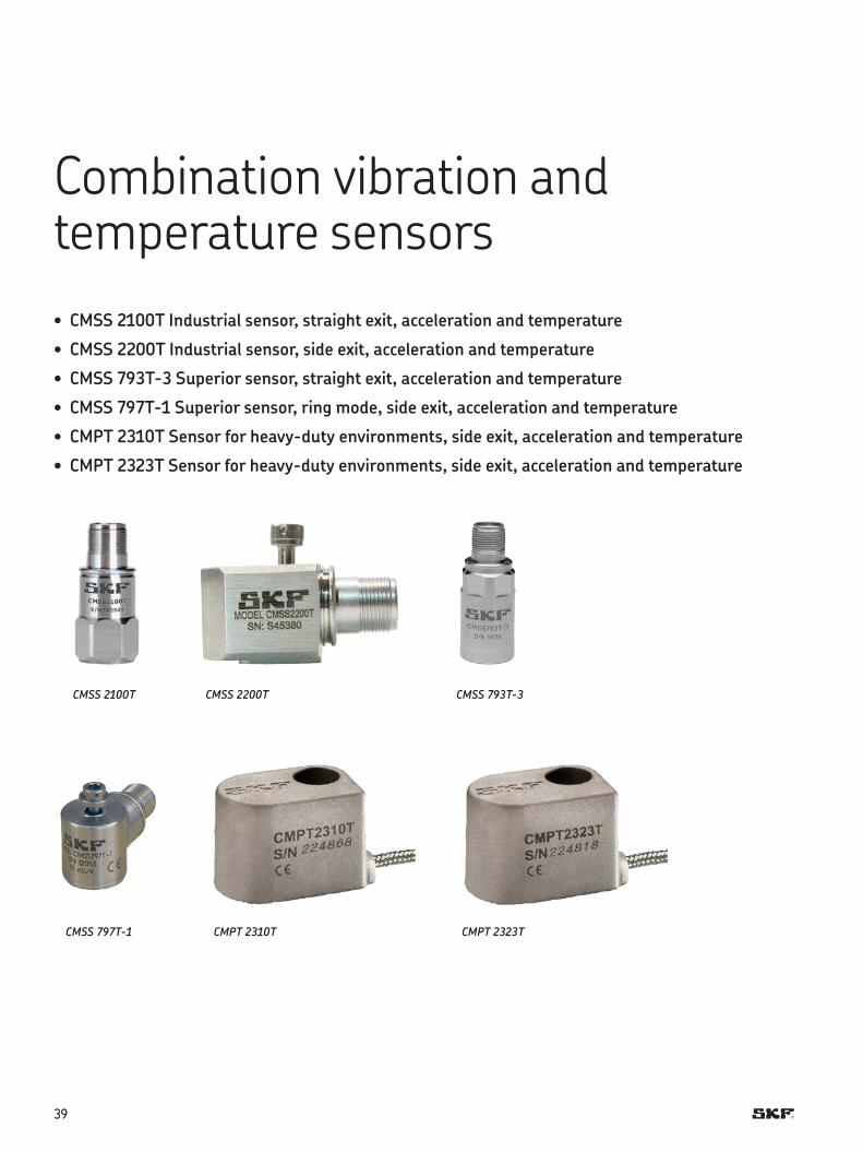
Combination vibration and temperature sensors
• CMSS 2100T Industrial sensor, straight exit, acceleration and temperature
• CMSS 2200T Industrial sensor, side exit, acceleration and temperature
• CMSS 793T-3 Superior sensor, straight exit, acceleration and temperature
• CMSS 797T-1 Superior sensor, ring mode, side exit, acceleration and temperature
• CMPT 2310T Sensor for heavy-duty environments, side exit, acceleration and temperature
• CMPT 2323T Sensor for heavy-duty environments, side exit, acceleration and temperature
CMSS 2100T
CMSS 797T-1
CMSS 2200T
CMPT 2310T
CMSS 793T-3
CMPT 2323T
4040
C
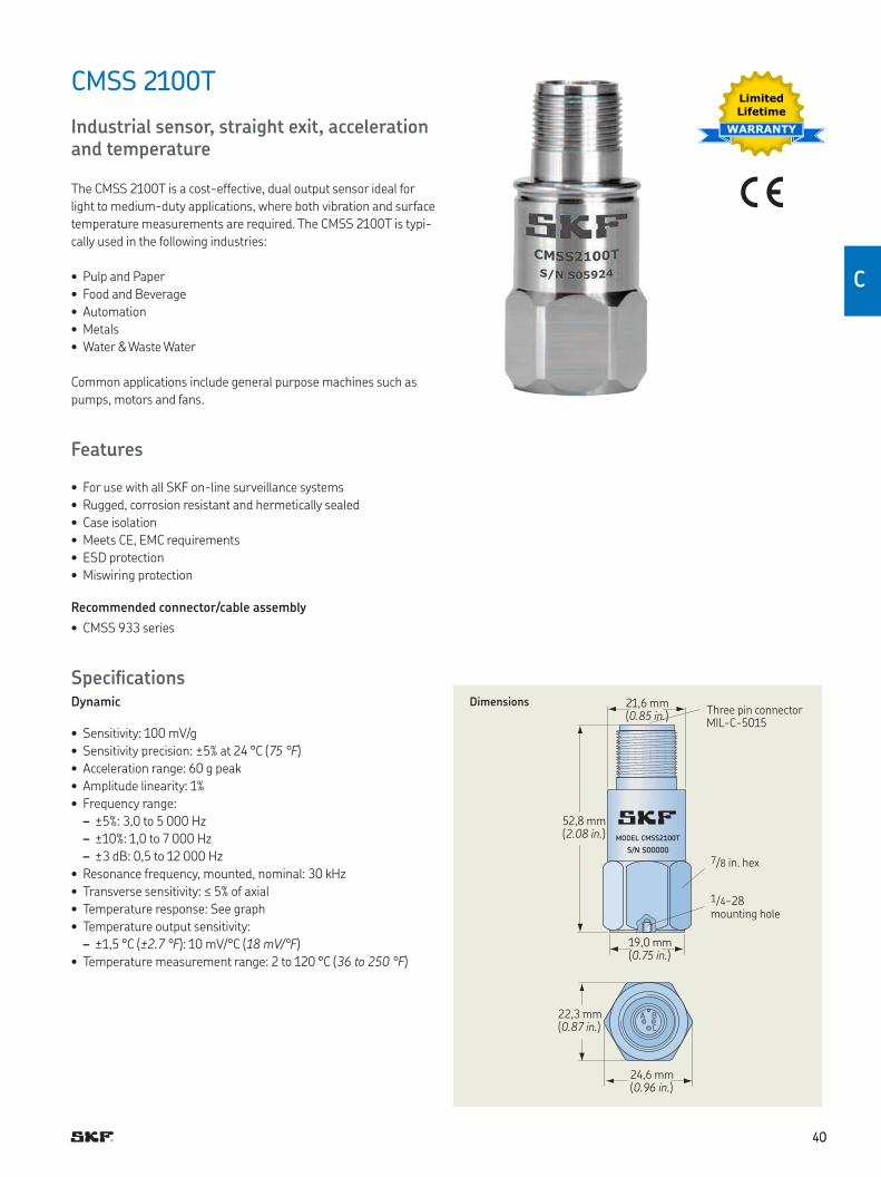
MODEL CMSS2100T
S/N S00000
A B
C
CMSS 2100T
Industrial sensor, straight exit, acceleration and temperature
The CMSS 2100T is a cost-effective, dual output sensor ideal for
light to medium-duty applications, where both vibration and surface
temperature measurements are required The CMSS 2100T is typi-
cally used in the following industries:
• Pulp and Paper
• Food and Beverage
• Automation
• Metals
• Water & Waste Water
Common applications include general purpose machines such as
pumps, motors and fans
Features
• For use with all SKF on-line surveillance systems
• Rugged, corrosion resistant and hermetically sealed
• Case isolation
• Meets CE, EMC requirements
• ESD protection
• Miswiring protection
Recommended connector/cable assembly
• CMSS 933 series
SpeciicationsDynamic
• Sensitivity: 100 mV/g
• Sensitivity precision: ±5% at 24 °C (75 °F)
• Acceleration range: 60 g peak
• Amplitude linearity: 1%
• Frequency range:
– ±5%: 3,0 to 5 000 Hz
– ±10%: 1,0 to 7 000 Hz
– ±3 dB: 0,5 to 12 000 Hz
• Resonance frequency, mounted, nominal: 30 kHz
• Transverse sensitivity: ≤ 5% of axial
• Temperature response: See graph
• Temperature output sensitivity:
– ±1,5 °C (±2.7 °F): 10 mV/°C (18 mV/°F)
• Temperature measurement range: 2 to 120 °C (36 to 250 °F)
Dimensions
1/4-28 mounting hole
7/8 in hex
Three pin connector MIL-C-5015
Limited
Lifetime
WARRANTY
52,8 mm (2.08 in.)
19,0 mm (0.75 in.)
24,6 mm (0.96 in.)
22,3 mm (0.87 in.)
21,6 mm (0.85 in.)
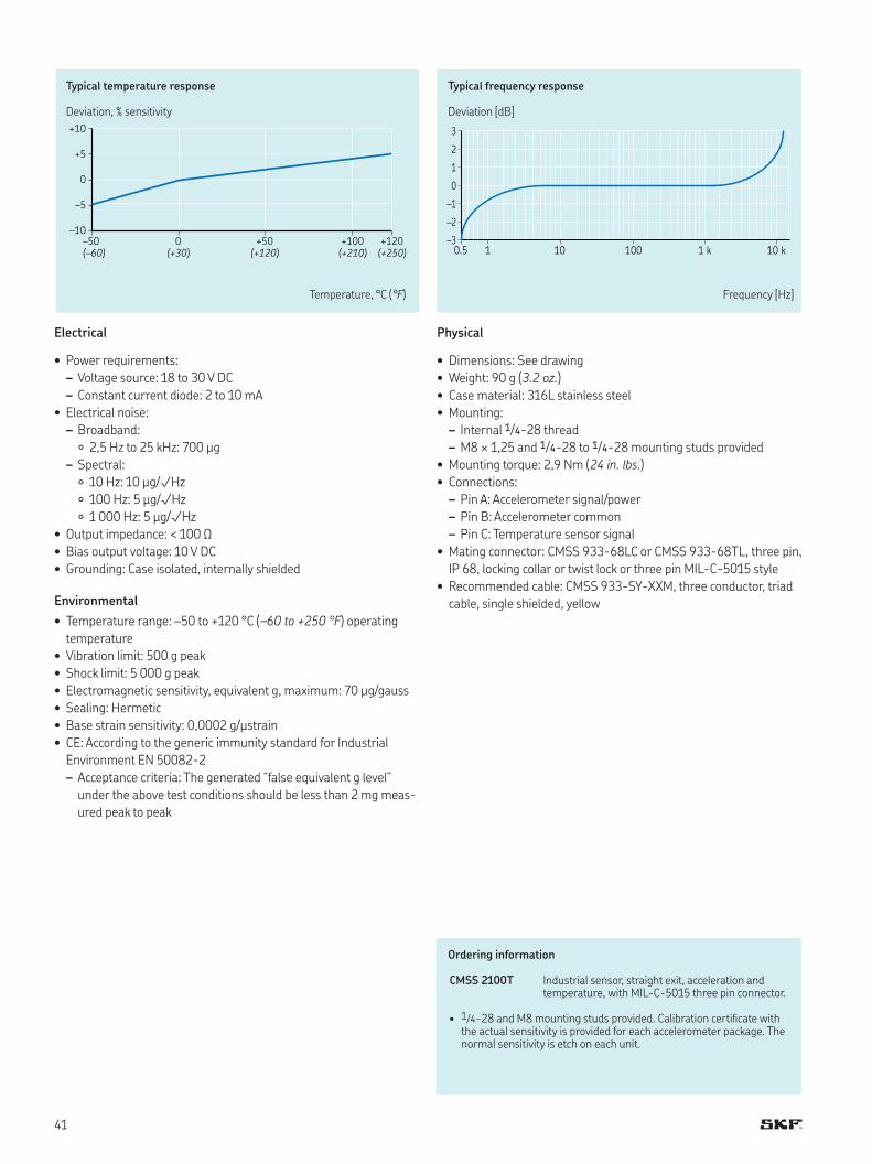
3
2
1
0
–1
–2
–30.5 1 10 100 1 k 10 k
+10
+5
0
–5
–10
–50 0 +50 +100 +120
(–60) (+30) (+120) (+210) (+250)
Typical temperature response
Deviation, % sensitivity
Typical frequency response
Deviation [dB]
Temperature, °C (°F) Frequency [Hz]
Electrical
• Power requirements:
– Voltage source: 18 to 30 V DC
– Constant current diode: 2 to 10 mA
• Electrical noise:
– Broadband:
2,5 Hz to 25 kHz: 700 µg
– Spectral:
10 Hz: 10 µg/√Hz
100 Hz: 5 µg/√Hz
1 000 Hz: 5 µg/√Hz
• Output impedance: < 100 Ω
• Bias output voltage: 10 V DC
• Grounding: Case isolated, internally shielded
Environmental
• Temperature range: –50 to +120 °C (–60 to +250 °F) operating
temperature
• Vibration limit: 500 g peak
• Shock limit: 5 000 g peak
• Electromagnetic sensitivity, equivalent g, maximum: 70 µg/gauss
• Sealing: Hermetic
• Base strain sensitivity: 0,0002 g/µstrain
• CE: According to the generic immunity standard for Industrial
Environment EN 50082-2
– Acceptance criteria: The generated “false equivalent g level”
under the above test conditions should be less than 2 mg meas-
ured peak to peak
Physical
• Dimensions: See drawing
• Weight: 90 g (3.2 oz.)
• Case material: 316L stainless steel
• Mounting:
– Internal 1/4-28 thread
– M8 × 1,25 and 1/4-28 to 1/4-28 mounting studs provided
• Mounting torque: 2,9 Nm (24 in. lbs.)
• Connections:
– Pin A: Accelerometer signal/power
– Pin B: Accelerometer common
– Pin C: Temperature sensor signal
• Mating connector: CMSS 933-68LC or CMSS 933-68TL, three pin,
IP 68, locking collar or twist lock or three pin MIL-C-5015 style
• Recommended cable: CMSS 933-SY-XXM, three conductor, triad
cable, single shielded, yellow
Ordering information
CMSS 2100T Industrial sensor, straight exit, acceleration and temperature, with MIL-C-5015 three pin connector
• 1/4-28 and M8 mounting studs provided Calibration certiicate with the actual sensitivity is provided for each accelerometer package The normal sensitivity is etch on each unit
41
4242
C
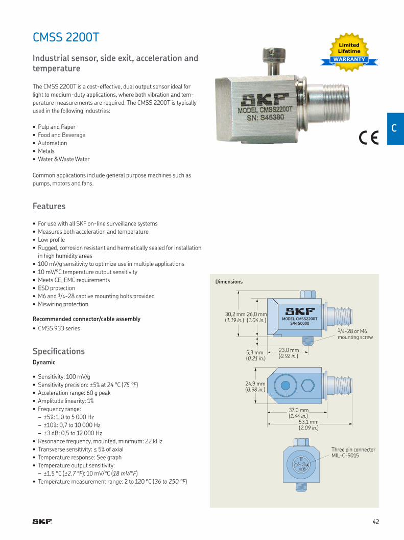
MODEL CMSS2200T
S/N S0000
C A
B
CMSS 2200T
Industrial sensor, side exit, acceleration and temperature
The CMSS 2200T is a cost-effective, dual output sensor ideal for
light to medium-duty applications, where both vibration and tem-
perature measurements are required The CMSS 2200T is typically
used in the following industries:
• Pulp and Paper
• Food and Beverage
• Automation
• Metals
• Water & Waste Water
Common applications include general purpose machines such as
pumps, motors and fans
Features
• For use with all SKF on-line surveillance systems
• Measures both acceleration and temperature
• Low proile
• Rugged, corrosion resistant and hermetically sealed for installation
in high humidity areas
• 100 mV/g sensitivity to optimize use in multiple applications
• 10 mV/°C temperature output sensitivity
• Meets CE, EMC requirements
• ESD protection
• M6 and 1/4-28 captive mounting bolts provided
• Miswiring protection
Recommended connector/cable assembly
• CMSS 933 series
SpeciicationsDynamic
• Sensitivity: 100 mV/g
• Sensitivity precision: ±5% at 24 °C (75 °F)
• Acceleration range: 60 g peak
• Amplitude linearity: 1%
• Frequency range:
– ±5%: 1,0 to 5 000 Hz
– ±10%: 0,7 to 10 000 Hz
– ±3 dB: 0,5 to 12 000 Hz
• Resonance frequency, mounted, minimum: 22 kHz
• Transverse sensitivity: ≤ 5% of axial
• Temperature response: See graph
• Temperature output sensitivity:
– ±1,5 °C (±2.7 °F): 10 mV/°C (18 mV/°F)
• Temperature measurement range: 2 to 120 °C (36 to 250 °F)
Dimensions
1/4-28 or M6 mounting screw
Three pin connector MIL-C-5015
30,2 mm (1.19 in.)
26,0 mm (1.04 in.)
5,3 mm (0.21 in.)
23,0 mm (0.92 in.)
24,9 mm (0.98 in.)
37,0 mm (1.44 in.)
53,1 mm (2.09 in.)
Limited
Lifetime
WARRANTY
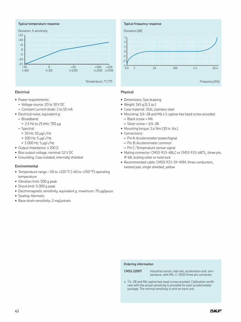
4343
3
2
1
0
–1
–2
–30.5 1 10 100 1 k 10 k
+15
+10
+5
0
–5
–10
–15
–50 0 +50 +100 +120
(–60) (+30) (+120) (+210) (+250)
Typical temperature response
Deviation, % sensitivity
Typical frequency response
Deviation [dB]
Temperature, °C (°F) Frequency [Hz]
Electrical
• Power requirements:
– Voltage source: 20 to 30 V DC
– Constant current diode: 2 to 10 mA
• Electrical noise, equivalent g:
– Broadband:
2,5 Hz to 25 kHz: 700 µg
– Spectral:
10 Hz: 10 µg/√Hz
100 Hz: 5 µg/√Hz
1 000 Hz: 5 µg/√Hz
• Output impedance: ≤ 100 Ω
• Bias output voltage, nominal: 12 V DC
• Grounding: Case isolated, internally shielded
Environmental
• Temperature range: –50 to +120 °C (–60 to +250 °F) operating
temperature
• Vibration limit: 500 g peak
• Shock limit: 5 000 g peak
• Electromagnetic sensitivity, equivalent g, maximum: 70 µg/gauss
• Sealing: Hermetic
• Base strain sensitivity: 2 mg/µstrain
Physical
• Dimensions: See drawing
• Weight: 145 g (5 1 oz )
• Case material: 316L stainless steel
• Mounting: 1/4-28 and M6 x 1 captive hex head screw provided
– Black screw = M6
– Silver screw = 1/4-28
• Mounting torque: 3,4 Nm (30 in lbs )
• Connections:
– Pin A: Accelerometer power/signal
– Pin B: Accelerometer common
– Pin C: Temperature sensor signal
• Mating connector: CMSS 933-68LC or CMSS 933-68TL, three pin,
IP 68, locking collar or twist lock
• Recommended cable: CMSS 933-SY-XXM, three conductors,
twisted pair, single shielded, yellow
Ordering information
CMSS 2200T Industrial sensor, side exit, acceleration and tem-perature, with MIL-C-5015 three pin connector
• 1/4-28 and M6 captive hex head screw provided Calibration certii-cate with the actual sensitivity is provided for each accelerometer package The normal sensitivity is etch on each unit
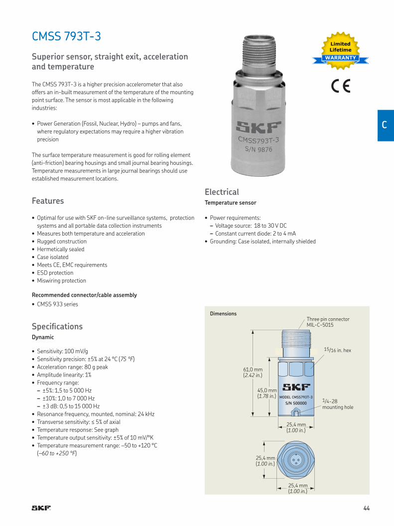
4444
C
MODEL CMSS793T-3
S/N S00000
CMSS 793T-3
Superior sensor, straight exit, acceleration and temperature
The CMSS 793T-3 is a higher precision accelerometer that also
offers an in-built measurement of the temperature of the mounting
point surface The sensor is most applicable in the following
industries:
• Power Generation (Fossil, Nuclear, Hydro) – pumps and fans,
where regulatory expectations may require a higher vibration
precision
The surface temperature measurement is good for rolling element
(anti-friction) bearing housings and small journal bearing housings
Temperature measurements in large journal bearings should use
established measurement locations
Features
• Optimal for use with SKF on-line surveillance systems, protection
systems and all portable data collection instruments
• Measures both temperature and acceleration
• Rugged construction
• Hermetically sealed
• Case isolated
• Meets CE, EMC requirements
• ESD protection
• Miswiring protection
Recommended connector/cable assembly
• CMSS 933 series
SpeciicationsDynamic
• Sensitivity: 100 mV/g
• Sensitivity precision: ±5% at 24 °C (75 °F)
• Acceleration range: 80 g peak
• Amplitude linearity: 1%
• Frequency range:
– ±5%: 1,5 to 5 000 Hz
– ±10%: 1,0 to 7 000 Hz
– ±3 dB: 0,5 to 15 000 Hz
• Resonance frequency, mounted, nominal: 24 kHz
• Transverse sensitivity: ≤ 5% of axial
• Temperature response: See graph
• Temperature output sensitivity: ±5% of 10 mV/°K
• Temperature measurement range: –50 to +120 °C
(–60 to +250 °F)
DimensionsThree pin connector MIL-C-5015
1/4-28 mounting hole
45,0 mm (1.78 in.)
15/16 in hex
61,0 mm (2.42 in.)
25,4 mm (1.00 in.)
25,4 mm (1.00 in.)
25,4 mm (1.00 in.)
Limited
Lifetime
WARRANTY
ElectricalTemperature sensor
• Power requirements:
– Voltage source: 18 to 30 V DC
– Constant current diode: 2 to 4 mA
• Grounding: Case isolated, internally shielded
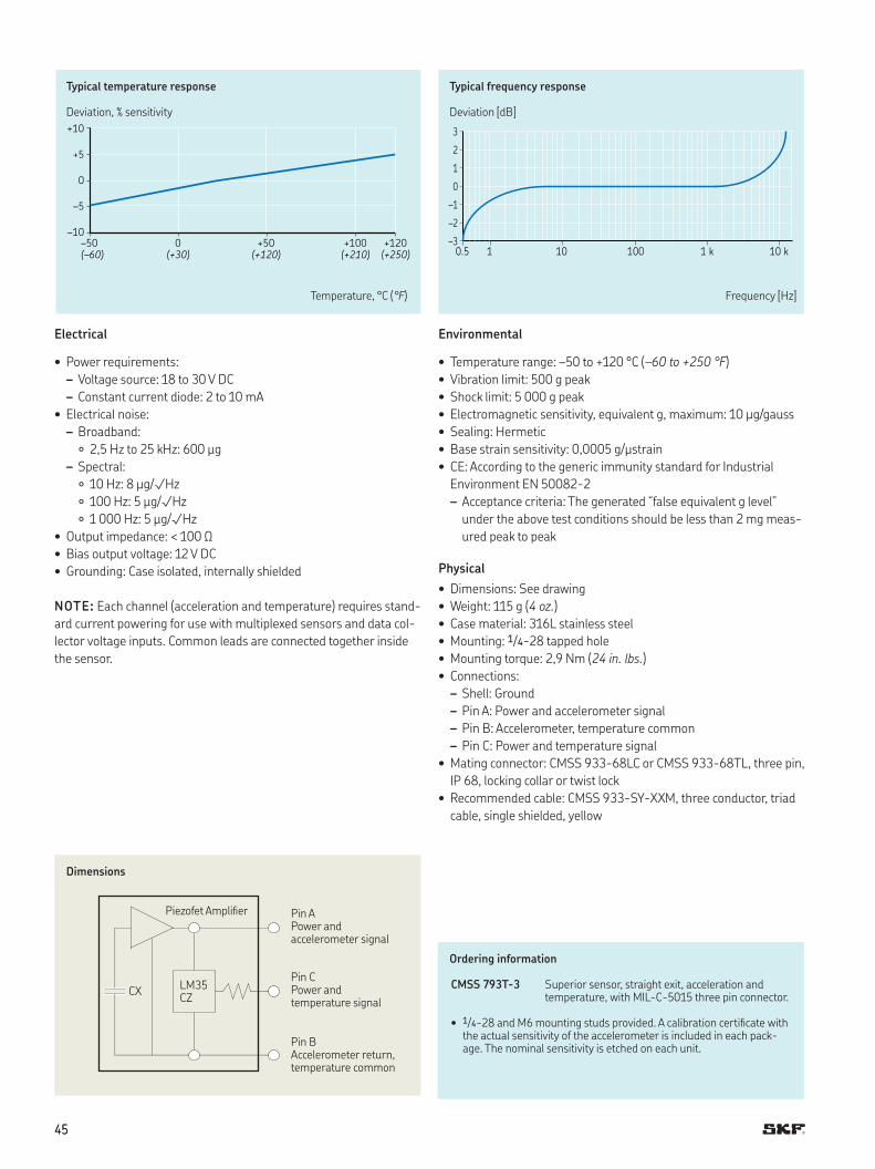
4545
3
2
1
0
–1
–2
–30.5 1 10 100 1 k 10 k
+10
+5
0
–5
–10
–50 0 +50 +100 +120
(–60) (+30) (+120) (+210) (+250)
Typical temperature response
Deviation, % sensitivity
Typical frequency response
Deviation [dB]
Temperature, °C (°F) Frequency [Hz]
Electrical
• Power requirements:
– Voltage source: 18 to 30 V DC
– Constant current diode: 2 to 10 mA
• Electrical noise:
– Broadband:
2,5 Hz to 25 kHz: 600 µg
– Spectral:
10 Hz: 8 µg/√Hz
100 Hz: 5 µg/√Hz
1 000 Hz: 5 µg/√Hz
• Output impedance: < 100 Ω
• Bias output voltage: 12 V DC
• Grounding: Case isolated, internally shielded
NOTE: Each channel (acceleration and temperature) requires stand-
ard current powering for use with multiplexed sensors and data col-
lector voltage inputs Common leads are connected together inside
the sensor
Ordering information
CMSS 793T-3 Superior sensor, straight exit, acceleration and temperature, with MIL-C-5015 three pin connector
• 1/4-28 and M6 mounting studs provided A calibration certiicate with the actual sensitivity of the accelerometer is included in each pack-age The nominal sensitivity is etched on each unit
Dimensions
Pin A Power and accelerometer signal
Piezofet Ampliier
LM35 CZ
CXPin C Power and temperature signal
Pin B Accelerometer return, temperature common
Environmental
• Temperature range: –50 to +120 °C (–60 to +250 °F)
• Vibration limit: 500 g peak
• Shock limit: 5 000 g peak
• Electromagnetic sensitivity, equivalent g, maximum: 10 µg/gauss
• Sealing: Hermetic
• Base strain sensitivity: 0,0005 g/µstrain
• CE: According to the generic immunity standard for Industrial
Environment EN 50082-2
– Acceptance criteria: The generated “false equivalent g level”
under the above test conditions should be less than 2 mg meas-
ured peak to peak
Physical
• Dimensions: See drawing
• Weight: 115 g (4 oz.)
• Case material: 316L stainless steel
• Mounting: 1/4-28 tapped hole
• Mounting torque: 2,9 Nm (24 in. lbs.)
• Connections:
– Shell: Ground
– Pin A: Power and accelerometer signal
– Pin B: Accelerometer, temperature common
– Pin C: Power and temperature signal
• Mating connector: CMSS 933-68LC or CMSS 933-68TL, three pin,
IP 68, locking collar or twist lock
• Recommended cable: CMSS 933-SY-XXM, three conductor, triad
cable, single shielded, yellow
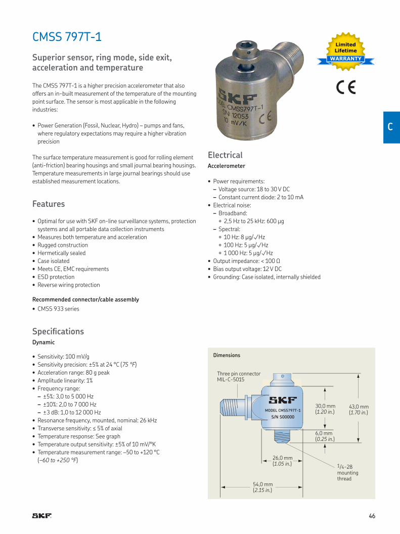
4646
C
CMSS 797T-1
Superior sensor, ring mode, side exit, acceleration and temperature
The CMSS 797T-1 is a higher precision accelerometer that also
offers an in-built measurement of the temperature of the mounting
point surface The sensor is most applicable in the following
industries:
• Power Generation (Fossil, Nuclear, Hydro) – pumps and fans,
where regulatory expectations may require a higher vibration
precision
The surface temperature measurement is good for rolling element
(anti-friction) bearing housings and small journal bearing housings
Temperature measurements in large journal bearings should use
established measurement locations
Features
• Optimal for use with SKF on-line surveillance systems, protection
systems and all portable data collection instruments
• Measures both temperature and acceleration
• Rugged construction
• Hermetically sealed
• Case isolated
• Meets CE, EMC requirements
• ESD protection
• Reverse wiring protection
Recommended connector/cable assembly
• CMSS 933 series
SpeciicationsDynamic
• Sensitivity: 100 mV/g
• Sensitivity precision: ±5% at 24 °C (75 °F)
• Acceleration range: 80 g peak
• Amplitude linearity: 1%
• Frequency range:
– ±5%: 3,0 to 5 000 Hz
– ±10%: 2,0 to 7 000 Hz
– ±3 dB: 1,0 to 12 000 Hz
• Resonance frequency, mounted, nominal: 26 kHz
• Transverse sensitivity: ≤ 5% of axial
• Temperature response: See graph
• Temperature output sensitivity: ±5% of 10 mV/°K
• Temperature measurement range: –50 to +120 °C
(–60 to +250 °F)
Limited
Lifetime
WARRANTY
MODEL CMSS797T-1
S/N S00000
Dimensions
Three pin connector MIL-C-5015
1/4-28 mounting thread
30,0 mm (1.20 in.)
43,0 mm (1.70 in.)
6,0 mm (0.25 in.)
26,0 mm (1.05 in.)
54,0 mm (2.15 in.)
ElectricalAccelerometer
• Power requirements:
– Voltage source: 18 to 30 V DC
– Constant current diode: 2 to 10 mA
• Electrical noise:
– Broadband:
2,5 Hz to 25 kHz: 600 µg
– Spectral:
10 Hz: 8 µg/√Hz
100 Hz: 5 µg/√Hz
1 000 Hz: 5 µg/√Hz
• Output impedance: < 100 Ω
• Bias output voltage: 12 V DC
• Grounding: Case isolated, internally shielded
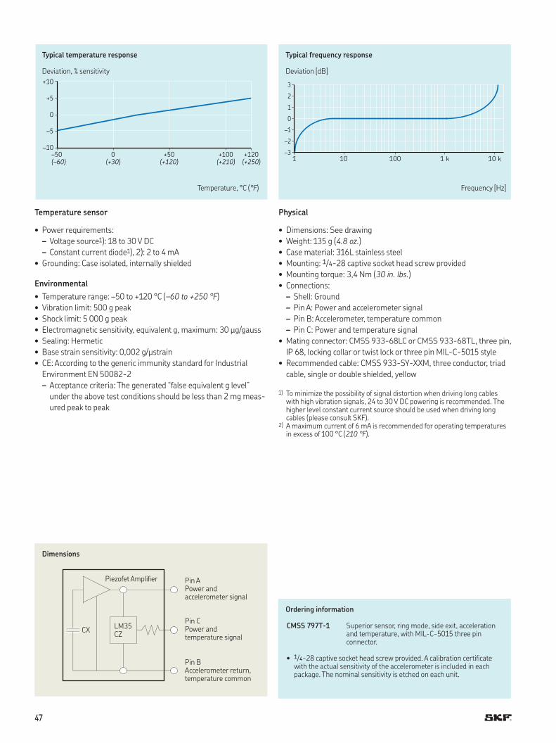
4747
3
2
1
0
–1
–2
–31 10 100 1 k 10 k
+10
+5
0
–5
–10
–50 0 +50 +100 +120
(–60) (+30) (+120) (+210) (+250)
Typical temperature response
Deviation, % sensitivity
Typical frequency response
Deviation [dB]
Temperature, °C (°F) Frequency [Hz]
Temperature sensor
• Power requirements:
– Voltage source1): 18 to 30 V DC
– Constant current diode1), 2): 2 to 4 mA
• Grounding: Case isolated, internally shielded
Environmental
• Temperature range: –50 to +120 °C (–60 to +250 °F)
• Vibration limit: 500 g peak
• Shock limit: 5 000 g peak
• Electromagnetic sensitivity, equivalent g, maximum: 30 µg/gauss
• Sealing: Hermetic
• Base strain sensitivity: 0,002 g/µstrain
• CE: According to the generic immunity standard for Industrial
Environment EN 50082-2
– Acceptance criteria: The generated “false equivalent g level”
under the above test conditions should be less than 2 mg meas-
ured peak to peak
Ordering information
CMSS 797T-1 Superior sensor, ring mode, side exit, acceleration and temperature, with MIL-C-5015 three pin connector
• 1/4-28 captive socket head screw provided A calibration certiicate with the actual sensitivity of the accelerometer is included in each package The nominal sensitivity is etched on each unit
Physical
• Dimensions: See drawing
• Weight: 135 g (4.8 oz.)
• Case material: 316L stainless steel
• Mounting: 1/4-28 captive socket head screw provided
• Mounting torque: 3,4 Nm (30 in. lbs.)
• Connections:
– Shell: Ground
– Pin A: Power and accelerometer signal
– Pin B: Accelerometer, temperature common
– Pin C: Power and temperature signal
• Mating connector: CMSS 933-68LC or CMSS 933-68TL, three pin,
IP 68, locking collar or twist lock or three pin MIL-C-5015 style
• Recommended cable: CMSS 933-SY-XXM, three conductor, triad
cable, single or double shielded, yellow
1) To minimize the possibility of signal distortion when driving long cables with high vibration signals, 24 to 30 V DC powering is recommended The higher level constant current source should be used when driving long cables (please consult SKF)
2) A maximum current of 6 mA is recommended for operating temperatures in excess of 100 °C (210 °F)
Dimensions
Pin A Power and accelerometer signal
Piezofet Ampliier
LM35 CZ
CXPin C Power and temperature signal
Pin B Accelerometer return, temperature common
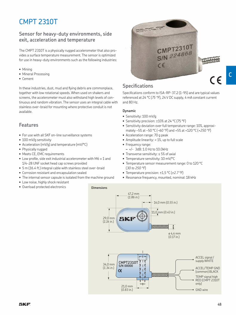
4848
C
CMPT 2310T
Sensor for heavy-duty environments, side exit, acceleration and temperature
The CMPT 2310T is a physically rugged accelerometer that also pro-
vides a surface temperature measurement The sensor is optimized
for use in heavy-duty environments such as the following industries:
• Mining
• Mineral Processing
• Cement
In these industries, dust, mud and lying debris are commonplace,
together with low rotational speeds When used on shakers and
screens, the accelerometer must also withstand high levels of con-
tinuous and random vibration The sensor uses an integral cable with
stainless over-braid for mounting where protective conduit is not
available
Features
• For use with all SKF on-line surveillance systems
• 100 mV/g sensitivity
• Acceleration (mV/g) and temperature (mV/°C)
• Physically rugged
• Meets CE, EMC requirements
• Low proile, side exit industrial accelerometer with M6 × 1 and
1/4-28 UNF socket head cap screws provided
• 5 m (16.4 ft.) integral cable with stainless steel over-braid
• Corrosion resistant and encapsulation sealed
• The internal sensor capsule is isolated from the machine ground
• Low noise, highly shock resistant
• Overload protected electronics
CMPT2310TS/N 00000
Dimensions
ACCEL signal / supply WHITE
TEMP signal high RED (CMPT 2310T only)
ACCEL/TEMP GND (common) BLACK
GND wire
47,2 mm (1.86 in.)
29,0 mm (1.14 in.)
14,0 mm (0.55 in.)
11,0 mm (0.43 in.)
ø 4,4 mm (0.17 in.)
34,0 mm (1.34 in.)
21,0 mm (0.83 in.)
SpeciicationsSpeciications conform to ISA-RP-37 2 (1-95) and are typical values
referenced at 24 °C (75 °F), 24 V DC supply, 4 mA constant current
and 80 Hz
Dynamic
• Sensitivity: 100 mV/g
• Sensitivity precision: ±10% at 24 °C (75 °F)
• Sensitivity deviation over full temperature range: 10%, approxi-
mately –5% at –50 °C (–60 °F) and +5% at +120 °C (+250 °F)
• Acceleration range: 70 g peak
• Amplitude linearity: < 1%, up to full scale
• Frequency range:
– +/- 3dB: 1 0 Hz to 10 0kHz
• Transverse sensitivity: ≤ 5% of axial
• Temperature sensitivity: 10 mV/°C
• Temperature sensor measurement range: 0 to 120 °C
(30 to 250 °F)
• Temperature precision: ±1,5 °C (±2.7 °F)
• Resonance frequency, mounted, nominal: 18 kHz

4949
Electrical
• Power requirements:
– Voltage source: 24 V DC nominal, 18 to 30 V DC
– Constant current diode: 4 mA at 24 V, 2 to 10 mA is permissible
• Electrical noise: < 1 mg RMS broadband 2,5 Hz to 25,0 kHz
• Bias output voltage: 11,5 V DC, ±10% for 24 V DC supply at
25 °C (77 °F)
• Grounding: Case isolated, internally shielded (Faraday cage)
– Faraday cage connected to power supply return
• Over-voltage protection: Approximately 18 V DC
• Reverse polarity (wiring) protection
Environmental
• Temperature range:
– Accelerometer measurement temperature range:
–50 to +120 °C (–60 to +250 °F)
– Maximum operating temperature: 120 °C (250 °F)
– Storage temperature: –50 to +150 °C (–60 to +300 °F)
• Vibration limit: 70 g peak
• Shock limit: 5 000 g peak
• Electromagnetic sensitivity, equivalent g, maximum: < 100 µg/
gauss at 50 to 60 Hz
• CE: According to the generic immunity standard for Industrial
Environment EN 50082-2
– Acceptance criteria: The generated “false equivalent g level”
under the above test conditions should be less than 2 mg meas-
ured peak to peak
• IEC: 529, IP 67 (For climatic conditions, recommend to use conduit/
hose over braided cable )
Ordering information
CMPT 2310T Acceleration and temperature sensor with 5 meter (16,4 ft) integral braided cable, side exit
CMPT 2310Tx10 Acceleration and temperature sensor with 10 meter (33 ft) integral braided cable, side exit
CMPT 2310Tx15 Acceleration and temperature sensor with 15 meter (50 ft) integral braided cable, side exit
• 1/4-28 and M6 × 1 socket head cap screws provided Calibration sen-sitivity is provided for each accelerometer package
Physical
• Dimensions: See drawing
• Weight:
– Sensor without cable: 210 g (7.4 oz.)
– Sensor with cable: 410 g (14.5 oz.)
• Case material: 304 stainless steel
• Mounting: M6 × 1 and 1/4-28 UNF socket head cap screws
provided
• Mounting torque: 6 Nm (50 in. lbs.)
• Cable: Integral cable, 5 m (16.4 ft.) length
• Wire speciication: 0,32 mm2 (AWG 22) stranded tin copper
(seven strands at 0,05 mm2 each)
• Connections:
– White: ACCEL signal/power
– Black: ACCEL/TEMP signal ground (GND)
– Red: TEMP signal high
– Blank twisted wire: Screen connected to internal shield
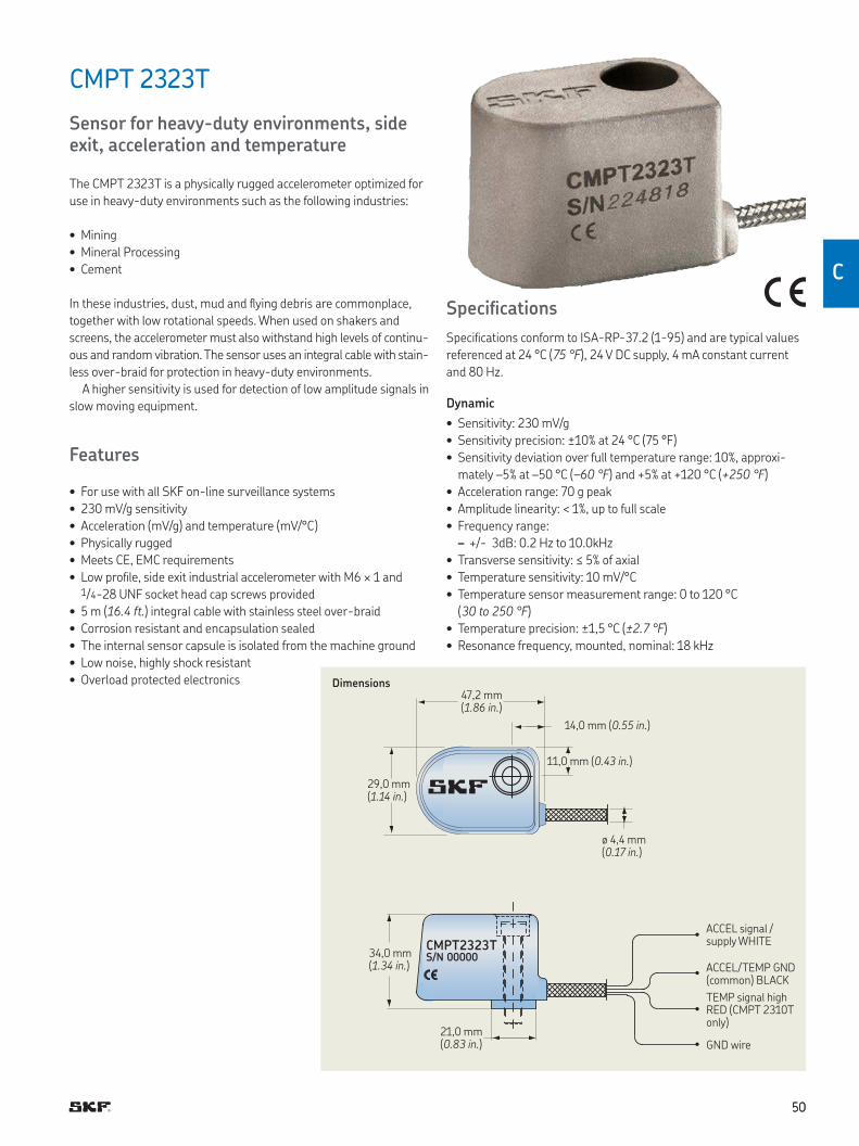
5050
C
CMPT 2323T
Sensor for heavy-duty environments, side exit, acceleration and temperature
The CMPT 2323T is a physically rugged accelerometer optimized for
use in heavy-duty environments such as the following industries:
• Mining
• Mineral Processing
• Cement
In these industries, dust, mud and lying debris are commonplace,
together with low rotational speeds When used on shakers and
screens, the accelerometer must also withstand high levels of continu-
ous and random vibration The sensor uses an integral cable with stain-
less over-braid for protection in heavy-duty environments
A higher sensitivity is used for detection of low amplitude signals in
slow moving equipment
Features
• For use with all SKF on-line surveillance systems
• 230 mV/g sensitivity
• Acceleration (mV/g) and temperature (mV/°C)
• Physically rugged
• Meets CE, EMC requirements
• Low proile, side exit industrial accelerometer with M6 × 1 and 1/4-28 UNF socket head cap screws provided
• 5 m (16.4 ft.) integral cable with stainless steel over-braid
• Corrosion resistant and encapsulation sealed
• The internal sensor capsule is isolated from the machine ground
• Low noise, highly shock resistant
• Overload protected electronics
CMPT2323TS/N 00000
Dimensions
ACCEL signal / supply WHITE
TEMP signal high RED (CMPT 2310T only)
ACCEL/TEMP GND (common) BLACK
GND wire
47,2 mm (1.86 in.)
29,0 mm (1.14 in.)
14,0 mm (0.55 in.)
11,0 mm (0.43 in.)
ø 4,4 mm (0.17 in.)
34,0 mm (1.34 in.)
21,0 mm (0.83 in.)
Speciications
Speciications conform to ISA-RP-37 2 (1-95) and are typical values
referenced at 24 °C (75 °F), 24 V DC supply, 4 mA constant current
and 80 Hz
Dynamic
• Sensitivity: 230 mV/g
• Sensitivity precision: ±10% at 24 °C (75 °F)
• Sensitivity deviation over full temperature range: 10%, approxi-
mately –5% at –50 °C (–60 °F) and +5% at +120 °C (+250 °F)
• Acceleration range: 70 g peak
• Amplitude linearity: < 1%, up to full scale
• Frequency range:
– +/- 3dB: 0 2 Hz to 10 0kHz
• Transverse sensitivity: ≤ 5% of axial
• Temperature sensitivity: 10 mV/°C
• Temperature sensor measurement range: 0 to 120 °C
(30 to 250 °F)
• Temperature precision: ±1,5 °C (±2.7 °F)
• Resonance frequency, mounted, nominal: 18 kHz
5151
Electrical
• Power requirements:
– Voltage source: 24 V DC nominal, 18 to 30 V DC
– Constant current diode: 4 mA at 24 V, 2 to 10 mA is permissible
• Electrical noise: < 1 mg RMS broadband 2,5 Hz to 25,0 kHz
• Bias output voltage: 11,5 V DC, ±10% for 24 V DC supply at 25 °C
(77 °F)
• Grounding: Case isolated, internally shielded (Faraday cage)
– Faraday cage connected to power supply return
• Over-voltage protection: Approximately 18 V DC
• Reverse polarity (wiring) protection
Environmental
• Temperature range:
– Accelerometer measurement temperature range:
–50 to +120 °C (–60 to +250 °F)
– Maximum operating temperature: 120 °C (250 °F)
– Storage temperature: –50 to +150 °C (–60 to +300 °F)
• Vibration limit: 70 g peak
• Shock limit: 5 000 g peak
• Electromagnetic sensitivity, equivalent g, maximum: < 100 µg/
gauss at 50 to 60 Hz
• CE: According to the generic immunity standard for Industrial
Environment EN 50082-2
– Acceptance criteria: The generated “false equivalent g level”
under the above test conditions should be less than 2 mg meas-
ured peak to peak
• IEC: 529, IP 67 (For climatic conditions, recommend to use conduit/
hose over braided cable )
Ordering information
CMPT 2323T Acceleration and temperature sensor, 230 mV/g, with 5 m (16,4 ft) integral braided cable, side exit
CMPT 2323Tx10 Acceleration and temperature sensor, 230 mV/g, with 10 m (33 ft) integral braided cable, side exit
CMPT 2323Tx15 Acceleration and temperature sensor, 230 mV/g, with 15 m (50 ft) integral braided cable, side exit
• 1/4-28 and M6 × 1 socket head cap screws provided Calibration sen-sitivity is provided for each accelerometer package
Physical
• Dimensions: See drawing
• Weight:
– Sensor without cable: 210 g (7.4 oz.)
– Sensor with cable: 410 g (14.5 oz.)
• Case material: 304 stainless steel
• Mounting: M6 × 1 and 1/4-28 UNF socket head cap screws
provided
• Mounting torque: 6 Nm (50 in. lbs.)
• Cable: Integral cable, 5 m (16.4 ft.) length
• Wire speciication: 0,32 mm2 (AWG 22) stranded tin copper
(seven strands at 0,05 mm2 each)
• Connections:
– White: ACCEL signal/power
– Black: ACCEL/TEMP signal ground (GND)
– Red: TEMP signal high
– Blank twisted wire: Screen connected to internal shield
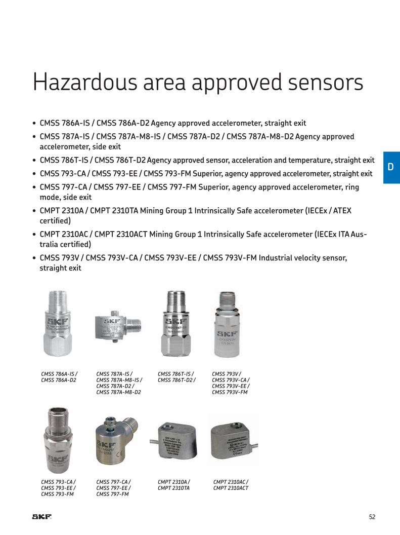
5252
D
Hazardous area approved sensors
• CMSS 786A-IS / CMSS 786A-D2 Agency approved accelerometer, straight exit
• CMSS 787A-IS / CMSS 787A-M8-IS / CMSS 787A-D2 / CMSS 787A-M8-D2 Agency approved accelerometer, side exit
• CMSS 786T-IS / CMSS 786T-D2 Agency approved sensor, acceleration and temperature, straight exit
• CMSS 793-CA / CMSS 793-EE / CMSS 793-FM Superior, agency approved accelerometer, straight exit
• CMSS 797-CA / CMSS 797-EE / CMSS 797-FM Superior, agency approved accelerometer, ring mode, side exit
• CMPT 2310A / CMPT 2310TA Mining Group 1 Intrinsically Safe accelerometer (IECEx / ATEX certiied)
• CMPT 2310AC / CMPT 2310ACT Mining Group 1 Intrinsically Safe accelerometer (IECEx ITA Aus-tralia certiied)
• CMSS 793V / CMSS 793V-CA / CMSS 793V-EE / CMSS 793V-FM Industrial velocity sensor, straight exit
CMSS 786A-IS / CMSS 786A-D2
CMSS 793-CA / CMSS 793-EE /CMSS 793-FM
CMSS 787A-IS / CMSS 787A-M8-IS /CMSS 787A-D2 / CMSS 787A-M8-D2
CMPT 2310A /CMPT 2310TA
CMSS 797-CA / CMSS 797-EE /CMSS 797-FM
CMSS 786T-IS / CMSS 786T-D2 /
CMSS 793V / CMSS 793V-CA / CMSS 793V-EE / CMSS 793V-FM
CMPT 2310AC /CMPT 2310ACT
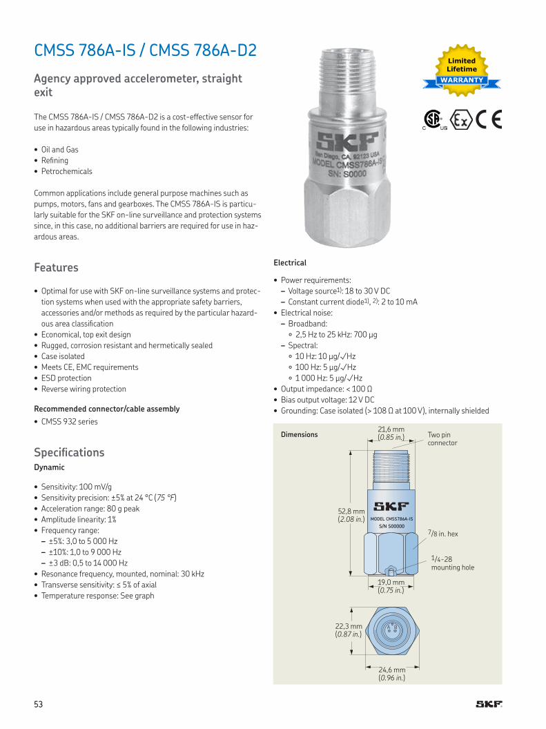
5353
CMSS 786A-IS / CMSS 786A-D2
Agency approved accelerometer, straight exit
The CMSS 786A-IS / CMSS 786A-D2 is a cost-effective sensor for
use in hazardous areas typically found in the following industries:
• Oil and Gas
• Reining
• Petrochemicals
Common applications include general purpose machines such as
pumps, motors, fans and gearboxes The CMSS 786A-IS is particu-
larly suitable for the SKF on-line surveillance and protection systems
since, in this case, no additional barriers are required for use in haz-
ardous areas
Features
• Optimal for use with SKF on-line surveillance systems and protec-
tion systems when used with the appropriate safety barriers,
accessories and/or methods as required by the particular hazard-
ous area classiication
• Economical, top exit design
• Rugged, corrosion resistant and hermetically sealed
• Case isolated
• Meets CE, EMC requirements
• ESD protection
• Reverse wiring protection
Recommended connector/cable assembly
• CMSS 932 series
SpeciicationsDynamic
• Sensitivity: 100 mV/g
• Sensitivity precision: ±5% at 24 °C (75 °F)
• Acceleration range: 80 g peak
• Amplitude linearity: 1%
• Frequency range:
– ±5%: 3,0 to 5 000 Hz
– ±10%: 1,0 to 9 000 Hz
– ±3 dB: 0,5 to 14 000 Hz
• Resonance frequency, mounted, nominal: 30 kHz
• Transverse sensitivity: ≤ 5% of axial
• Temperature response: See graph
MODEL CMSS786A-IS
S/N S00000
A B
Dimensions
1/4-28 mounting hole
Two pin connector
52,8 mm (2.08 in.)
19,0 mm (0.75 in.)
22,3 mm (0.87 in.)
24,6 mm (0.96 in.)
7/8 in hex
Electrical
• Power requirements:
– Voltage source1): 18 to 30 V DC
– Constant current diode1), 2): 2 to 10 mA
• Electrical noise:
– Broadband:
2,5 Hz to 25 kHz: 700 µg
– Spectral:
10 Hz: 10 µg/√Hz
100 Hz: 5 µg/√Hz
1 000 Hz: 5 µg/√Hz
• Output impedance: < 100 Ω
• Bias output voltage: 12 V DC
• Grounding: Case isolated (> 108 Ω at 100 V), internally shielded
Limited
Lifetime
WARRANTY
21,6 mm (0.85 in.)
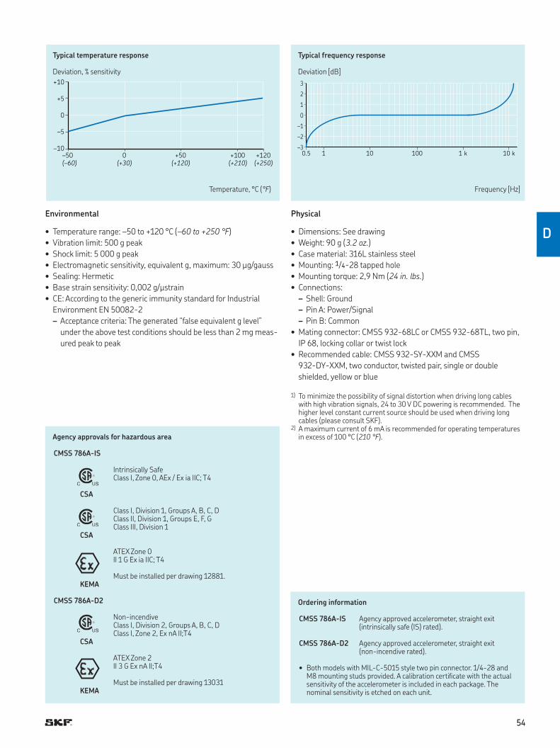
5454
D
3
2
1
0
–1
–2
–30.5 1 10 100 1 k 10 k
+10
+5
0
–5
–10
–50 0 +50 +100 +120
(–60) (+30) (+120) (+210) (+250)
Typical temperature response
Deviation, % sensitivity
Typical frequency response
Deviation [dB]
Temperature, °C (°F) Frequency [Hz]
Environmental
• Temperature range: –50 to +120 °C (–60 to +250 °F)
• Vibration limit: 500 g peak
• Shock limit: 5 000 g peak
• Electromagnetic sensitivity, equivalent g, maximum: 30 µg/gauss
• Sealing: Hermetic
• Base strain sensitivity: 0,002 g/µstrain
• CE: According to the generic immunity standard for Industrial
Environment EN 50082-2
– Acceptance criteria: The generated “false equivalent g level”
under the above test conditions should be less than 2 mg meas-
ured peak to peak
Ordering information
CMSS 786A-IS Agency approved accelerometer, straight exit (intrinsically safe (IS) rated)
CMSS 786A-D2 Agency approved accelerometer, straight exit (non-incendive rated)
• Both models with MIL-C-5015 style two pin connector 1/4-28 and M8 mounting studs provided A calibration certiicate with the actual sensitivity of the accelerometer is included in each package The nominal sensitivity is etched on each unit
Physical
• Dimensions: See drawing
• Weight: 90 g (3.2 oz.)
• Case material: 316L stainless steel
• Mounting: 1/4-28 tapped hole
• Mounting torque: 2,9 Nm (24 in. lbs.)
• Connections:
– Shell: Ground
– Pin A: Power/Signal
– Pin B: Common
• Mating connector: CMSS 932-68LC or CMSS 932-68TL, two pin,
IP 68, locking collar or twist lock
• Recommended cable: CMSS 932-SY-XXM and CMSS
932-DY-XXM, two conductor, twisted pair, single or double
shielded, yellow or blue
1) To minimize the possibility of signal distortion when driving long cables with high vibration signals, 24 to 30 V DC powering is recommended The higher level constant current source should be used when driving long cables (please consult SKF)
2) A maximum current of 6 mA is recommended for operating temperatures in excess of 100 °C (210 °F) Agency approvals for hazardous area
CMSS 786A-IS
Intrinsically SafeClass I, Zone 0, AEx / Ex ia IIC; T4
CSA
Class I, Division 1, Groups A, B, C, DClass II, Division 1, Groups E, F, GClass III, Division 1
CSA
ATEX Zone 0II 1 G Ex ia IIC; T4
Must be installed per drawing 12881 KEMA
CMSS 786A-D2
Non-incendiveClass I, Division 2, Groups A, B, C, DClass I, Zone 2, Ex nA II;T4
CSA
ATEX Zone 2II 3 G Ex nA II;T4
Must be installed per drawing 13031KEMA
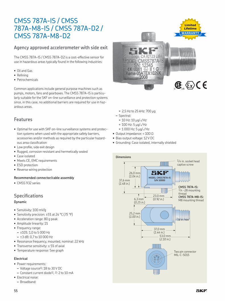
5555
CMSS 787A-IS / CMSS 787A-M8-IS / CMSS 787A-D2 / CMSS 787A-M8-D2
Agency approved accelerometer with side exit
The CMSS 787A-IS / CMSS 787A-D2 is a cost-effective sensor for
use in hazardous areas typically found in the following industries:
• Oil and Gas
• Reining
• Petrochemicals
Common applications include general purpose machines such as
pumps, motors, fans and gearboxes The CMSS 787A-IS is particu-
larly suitable for the SKF on-line surveillance and protection systems
since, in this case, no additional barriers are required for use in haz-
ardous areas
Features
• Optimal for use with SKF on-line surveillance systems and protec-
tion systems when used with the appropriate safety barriers,
accessories and/or methods as required by the particular hazard-
ous area classiication
• Low proile, side exit design
• Rugged, corrosion resistant and hermetically sealed
• Case isolated
• Meets CE, EMC requirements
• ESD protection
• Reverse wiring protection
Recommended connector/cable assembly
• CMSS 932 series
SpeciicationsDynamic
• Sensitivity: 100 mV/g
• Sensitivity precision: ±5% at 24 °C (75 °F)
• Acceleration range: 80 g peak
• Amplitude linearity: 1%
• Frequency range:
– ±10%: 1,0 to 5 000 Hz
– ±3 dB: 0,7 to 10 000 Hz
• Resonance frequency, mounted, nominal: 22 kHz
• Transverse sensitivity: ≤ 5% of axial
• Temperature response: See graph
Electrical
• Power requirements:
– Voltage source1): 18 to 30 V DC
– Constant current diode1), 2): 2 to 10 mA
• Electrical noise:
– Broadband:
MODEL CMSS787A-ISS/N S0000
A B
+ –
Dimensions
CMSS 787A-IS:1 /4 -28 mounting threadCMSS 787A-M8-IS:M8 mounting thread
1/4 in socket head captive screw
26,0 mm (1.04 in.)
37,6 mm (1.48 in.)
23,0 mm (0.92 in.)6,3 mm
(0.25 in.)
25,2 mm (1.00 in.)
37,0 mm (1.44 in.)
53,0 mm (2.10 in.)
Two pin connector MIL-C-5015
7/8 in hex
2,5 Hz to 25 kHz: 700 µg
– Spectral:
10 Hz: 10 µg/√Hz
100 Hz: 5 µg/√Hz
1 000 Hz: 5 µg/√Hz
• Output impedance: < 100 Ω
• Bias output voltage: 12 V DC
• Grounding: Case isolated, internally shielded
Limited
Lifetime
WARRANTY
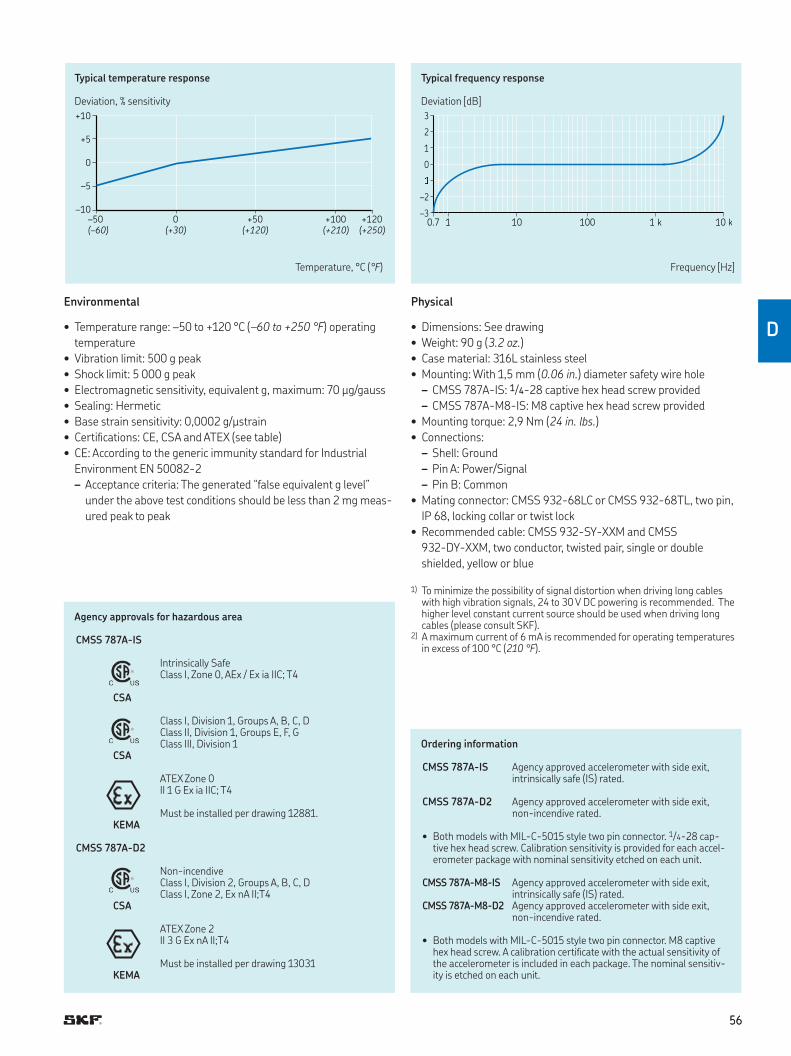
5656
D
3
2
1
0
–2
–30.7 1 10 100 1 k 10 k
+10
+5
0
–5
–10
–50 0 +50 +100 +120
(–60) (+30) (+120) (+210) (+250)
Typical temperature response
Deviation, % sensitivity
Typical frequency response
Deviation [dB]
Temperature, °C (°F) Frequency [Hz]
Environmental
• Temperature range: –50 to +120 °C (–60 to +250 °F) operating
temperature
• Vibration limit: 500 g peak
• Shock limit: 5 000 g peak
• Electromagnetic sensitivity, equivalent g, maximum: 70 µg/gauss
• Sealing: Hermetic
• Base strain sensitivity: 0,0002 g/µstrain
• Certiications: CE, CSA and ATEX (see table)
• CE: According to the generic immunity standard for Industrial
Environment EN 50082-2
– Acceptance criteria: The generated “false equivalent g level”
under the above test conditions should be less than 2 mg meas-
ured peak to peak
Ordering information
CMSS 787A-IS Agency approved accelerometer with side exit, intrinsically safe (IS) rated
CMSS 787A-D2 Agency approved accelerometer with side exit, non-incendive rated
• Both models with MIL-C-5015 style two pin connector 1/4-28 cap-tive hex head screw Calibration sensitivity is provided for each accel-erometer package with nominal sensitivity etched on each unit
CMSS 787A-M8-IS Agency approved accelerometer with side exit, intrinsically safe (IS) rated
CMSS 787A-M8-D2 Agency approved accelerometer with side exit, non-incendive rated
• Both models with MIL-C-5015 style two pin connector M8 captive hex head screw A calibration certiicate with the actual sensitivity of the accelerometer is included in each package The nominal sensitiv-ity is etched on each unit
Physical
• Dimensions: See drawing
• Weight: 90 g (3.2 oz.)
• Case material: 316L stainless steel
• Mounting: With 1,5 mm (0.06 in.) diameter safety wire hole
– CMSS 787A-IS: 1/4-28 captive hex head screw provided
– CMSS 787A-M8-IS: M8 captive hex head screw provided
• Mounting torque: 2,9 Nm (24 in. lbs.)
• Connections:
– Shell: Ground
– Pin A: Power/Signal
– Pin B: Common
• Mating connector: CMSS 932-68LC or CMSS 932-68TL, two pin,
IP 68, locking collar or twist lock
• Recommended cable: CMSS 932-SY-XXM and CMSS
932-DY-XXM, two conductor, twisted pair, single or double
shielded, yellow or blue
1) To minimize the possibility of signal distortion when driving long cables with high vibration signals, 24 to 30 V DC powering is recommended The higher level constant current source should be used when driving long cables (please consult SKF)
2) A maximum current of 6 mA is recommended for operating temperatures in excess of 100 °C (210 °F)
Agency approvals for hazardous area
CMSS 787A-IS
Intrinsically SafeClass I, Zone 0, AEx / Ex ia IIC; T4
CSA
Class I, Division 1, Groups A, B, C, DClass II, Division 1, Groups E, F, GClass III, Division 1
CSA
ATEX Zone 0II 1 G Ex ia IIC; T4
Must be installed per drawing 12881 KEMA
CMSS 787A-D2
Non-incendiveClass I, Division 2, Groups A, B, C, DClass I, Zone 2, Ex nA II;T4
CSA
ATEX Zone 2II 3 G Ex nA II;T4
Must be installed per drawing 13031KEMA
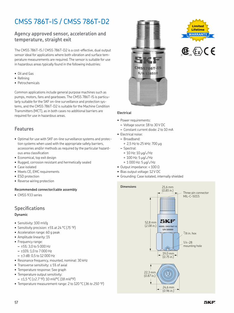
5757
CMSS 786T-IS / CMSS 786T-D2
Agency approved sensor, acceleration and temperature, straight exit
The CMSS 786T-IS / CMSS 786T-D2 is a cost-effective, dual output
sensor ideal for applications where both vibration and surface tem-
perature measurements are required The sensor is suitable for use
in hazardous areas typically found in the following industries:
• Oil and Gas
• Reining
• Petrochemicals
Common applications include general purpose machines such as
pumps, motors, fans and gearboxes The CMSS 786T-IS is particu-
larly suitable for the SKF on-line surveillance and protection sys-
tems, and the CMSS 786T-D2 is suitable for the Machine Condition
Transmitters (MCT), as in both cases no additional barriers are
required for use in hazardous areas
Features
• Optimal for use with SKF on-line surveillance systems and protec-
tion systems when used with the appropriate safety barriers,
accessories and/or methods as required by the particular hazard-
ous area classiication
• Economical, top exit design
• Rugged, corrosion resistant and hermetically sealed
• Case isolated
• Meets CE, EMC requirements
• ESD protection
• Reverse wiring protection
Recommended connector/cable assembly
• CMSS 933 series
SpeciicationsDynamic
• Sensitivity: 100 mV/g
• Sensitivity precision: ±5% at 24 °C (75 °F)
• Acceleration range: 60 g peak
• Amplitude linearity: 1%
• Frequency range:
– ±5%: 3,0 to 5 000 Hz
– ±10%: 1,0 to 7 000 Hz
– ±3 dB: 0,5 to 12 000 Hz
• Resonance frequency, mounted, nominal: 30 kHz
• Transverse sensitivity: ≤ 5% of axial
• Temperature response: See graph
• Temperature output sensitivity:
– ±1,5 °C (±2.7 °F): 10 mV/°C (18 mV/°F)
• Temperature measurement range: 2 to 120 °C (36 to 250 °F)
MODEL CMSS786T-IS
S/N S00000
A B
C
Dimensions
Three pin connector MIL-C-5015
52,8 mm (2.08 in.)
22,3 mm (0.87 in.)
19,0 mm (0.75 in.)
24,6 mm (0.96 in.)
1/4-28 mounting hole
7/8 in hex
Electrical
• Power requirements:
– Voltage source: 18 to 30 V DC
– Constant current diode: 2 to 10 mA
• Electrical noise:
– Broadband:
2,5 Hz to 25 kHz: 700 µg
– Spectral:
10 Hz: 10 µg/√Hz
100 Hz: 5 µg/√Hz
1 000 Hz: 5 µg/√Hz
• Output impedance: < 100 Ω
• Bias output voltage: 12 V DC
• Grounding: Case isolated, internally shielded
Limited
Lifetime
WARRANTY
21,6 mm (0.85 in.)
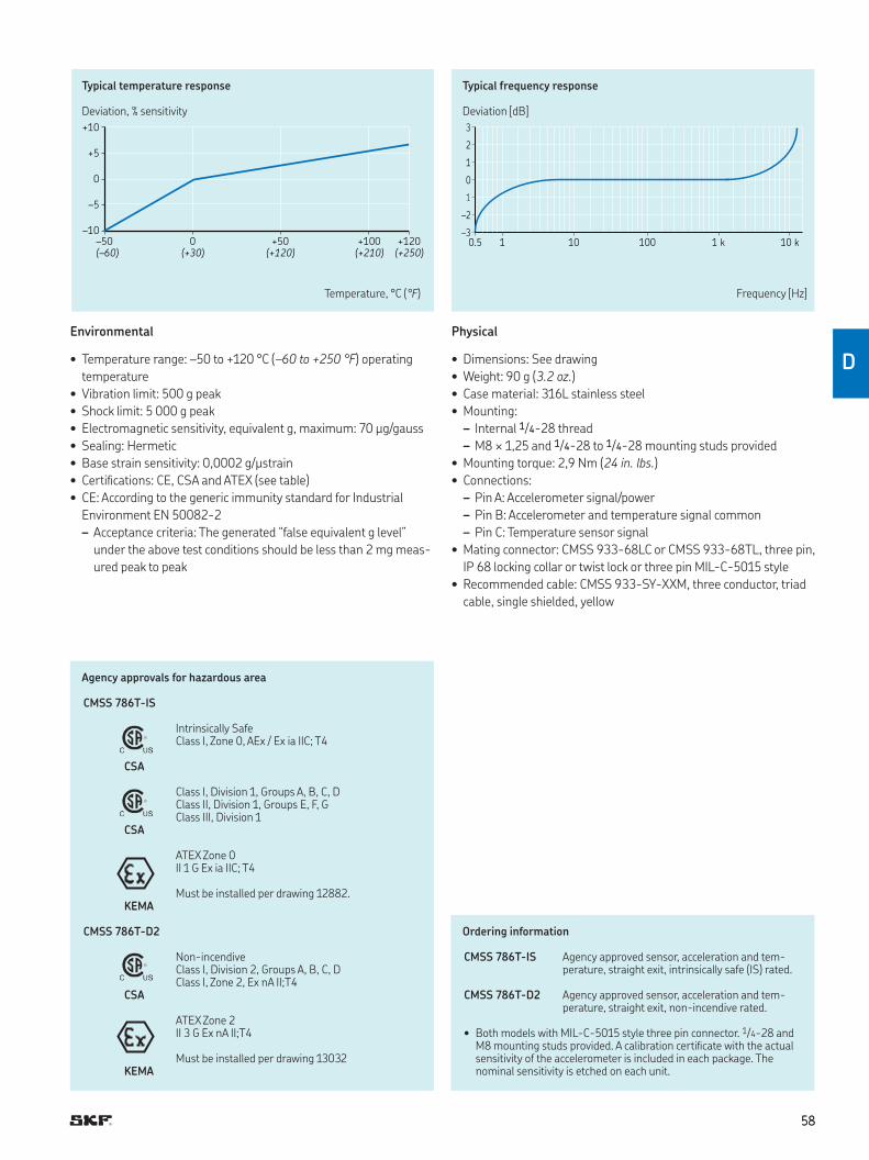
5858
D
3
2
1
0
–2
–30.5 1 10 100 1 k 10 k
+10
+5
0
–5
–10
–50 0 +50 +100 +120
(–60) (+30) (+120) (+210) (+250)
Typical temperature response
Deviation, % sensitivity
Typical frequency response
Deviation [dB]
Temperature, °C (°F) Frequency [Hz]
Environmental
• Temperature range: –50 to +120 °C (–60 to +250 °F) operating
temperature
• Vibration limit: 500 g peak
• Shock limit: 5 000 g peak
• Electromagnetic sensitivity, equivalent g, maximum: 70 µg/gauss
• Sealing: Hermetic
• Base strain sensitivity: 0,0002 g/µstrain
• Certiications: CE, CSA and ATEX (see table)
• CE: According to the generic immunity standard for Industrial
Environment EN 50082-2
– Acceptance criteria: The generated “false equivalent g level”
under the above test conditions should be less than 2 mg meas-
ured peak to peak
Ordering information
CMSS 786T-IS Agency approved sensor, acceleration and tem-perature, straight exit, intrinsically safe (IS) rated
CMSS 786T-D2 Agency approved sensor, acceleration and tem-perature, straight exit, non-incendive rated
• Both models with MIL-C-5015 style three pin connector 1/4-28 and M8 mounting studs provided A calibration certiicate with the actual sensitivity of the accelerometer is included in each package The nominal sensitivity is etched on each unit
Physical
• Dimensions: See drawing
• Weight: 90 g (3.2 oz.)
• Case material: 316L stainless steel
• Mounting:
– Internal 1/4-28 thread
– M8 × 1,25 and 1/4-28 to 1/4-28 mounting studs provided
• Mounting torque: 2,9 Nm (24 in. lbs.)
• Connections:
– Pin A: Accelerometer signal/power
– Pin B: Accelerometer and temperature signal common
– Pin C: Temperature sensor signal
• Mating connector: CMSS 933-68LC or CMSS 933-68TL, three pin,
IP 68 locking collar or twist lock or three pin MIL-C-5015 style
• Recommended cable: CMSS 933-SY-XXM, three conductor, triad
cable, single shielded, yellow
Agency approvals for hazardous area
CMSS 786T-IS
Intrinsically SafeClass I, Zone 0, AEx / Ex ia IIC; T4
CSA
Class I, Division 1, Groups A, B, C, DClass II, Division 1, Groups E, F, GClass III, Division 1
CSA
ATEX Zone 0II 1 G Ex ia IIC; T4
Must be installed per drawing 12882 KEMA
CMSS 786T-D2
Non-incendiveClass I, Division 2, Groups A, B, C, DClass I, Zone 2, Ex nA II;T4
CSA
ATEX Zone 2II 3 G Ex nA II;T4
Must be installed per drawing 13032KEMA
5959
CMSS 793-CA / CMSS 793-EE / CMSS 793-FM
Superior, agency approved accelerometer, straight exit
The CMSS 793-CA, CMSS 793-EE and CMSS 793-FM are superior
acceleration sensors with a top exit, two pin connector and agency
approvals They are based on the CMSS 793 sensor speciications
Features
• Agency approval
– CMSS 793-CA: Canadian Standards Association (CSA)
Class I, II, III, Division 1 certiication
– CMSS 793-EE: ATEX Zone 0 intrinsically safe (IS) certiication
– CMSS 793-FM: Factory Mutual (FM) intrinsically safe (IS)
certiication
• Ground isolated
• Rugged construction
• Corrosion resistant and hermetically sealed for installation in high
humidity areas
• Meets CE, EMC requirements
• ESD protection
• Reverse wiring protection
For more information about this hazardous area approved sensor,
refer to the section Industrial accelerometers for widespread applica-
tions († page 18).
Limited
Lifetime
WARRANTY
Ordering information
CMSS 793-CA Superior, CSA approved accelerometer, straight exit
CMSS 793-EE Superior, ATEX approved accelerometer, straight exit
CMSS 793-FM Superior, FM approved accelerometer, straight exit
• 1/4-28 mounting studs are provided for all models A calibration cer-tiicate with the actual sensitivity of the accelerometer is included in each package The nominal sensitivity is etched on each unit
Optional accessories
CMSS 908-MD Medium duty magnetic base
Agency approvals for hazardous area
CMSS 793-CA
Class I, Division 1, Groups A, B, C, D
Must be installed per drawing 31256700CSA
CMSS 793-EE
ATEX Zone 0II 1 GEx ia IIC T4 Ga (Ta = –50 to +120 °C (–60 to +250 °F)
SIRAMust be installed per drawing 11535
CMSS 793-FM
Intrinsically SafeClass I, II, III, Division 1, Groups A, B, C, D, E, F, GNIClass I, II, III, Division 2, Groups A, B, C, D, F, G
FMMust be installed per document drawing set 31533600
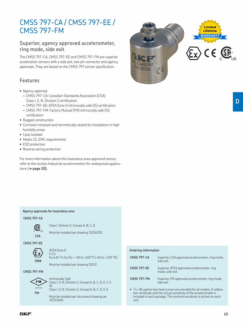
6060
D
CMSS 797-CA / CMSS 797-EE / CMSS 797-FM
Superior, agency approved accelerometer, ring mode, side exit
The CMSS 797-CA, CMSS 797-EE and CMSS 797-FM are superior
acceleration sensors with a side exit, two pin connector and agency
approvals They are based on the CMSS 797 sensor speciication
Features
• Agency approval
– CMSS 797-CA: Canadian Standards Association (CSA)
Class I, II, III, Division 1 certiication
– CMSS 797-EE: ATEX Zone 0 intrinsically safe (IS) certiication
– CMSS 797-FM: Factory Mutual (FM) intrinsically safe (IS)
certiication
• Rugged construction
• Corrosion resistant and hermetically sealed for installation in high
humidity areas
• Case isolated
• Meets CE, EMC requirements
• ESD protection
• Reverse wiring protection
For more information about this hazardous area approved sensor,
refer to the section Industrial accelerometers for widespread applica-
tions († page 20).
Ordering information
CMSS 797-CA Superior, CSA approved accelerometer, ring mode, side exit
CMSS 797-EE Superior, ATEX approved accelerometer, ring mode, side exit
CMSS 797-FM Superior, FM approved accelerometer, ring mode, side exit
• 1/4-28 captive hex head screws are provided for all models A calibra-tion certiicate with the actual sensitivity of the accelerometer is included in each package The nominal sensitivity is etched on each unit
Agency approvals for hazardous area
CMSS 797-CA
Class I, Division 1, Groups A, B, C, D
Must be installed per drawing 31256700 CSA
CMSS 797-EE
ATEX Zone 0II 1 GEx ia IIC T4 Ga (Ta = –50 to +120 °C (–60 to +250 °F))
SIRAMust be installed per drawing 11537
CMSS 797-FM
Intrinsically SafeClass I, II, III, Division 1, Groups A, B, C, D, E, F, GNIClass I, II, III, Division 2, Groups A, B, C, D, F, G
FMMust be installed per document drawing set 31533600
Limited
Lifetime
WARRANTY
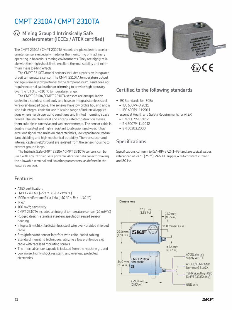
6161
CMPT 2310A / CMPT 2310TA
Mining Group 1 Intrinsically Safe accelerometer (IECEx / ATEX certiied)
The CMPT 2310A / CMPT 2310TA models are piezoelectric acceler-
ometer sensors especially made for the monitoring of machinery
operating in hazardous mining environments They are highly relia-
ble with their high shock limit, excellent thermal stability and mini-
mum mass loading effects
The CMPT 2310TA model sensors includes a precision integrated
circuit temperature sensor The CMPT 2310TA temperature output
voltage is linearly proportional to the temperature (°C) and does not
require external calibration or trimming to provide high accuracy
over the full 0 to +110 °C temperature range
The CMPT 2310A / CMPT 2310TA sensors are encapsulation
sealed in a stainless steel body and have an integral stainless steel
wire over-braided cable The sensors have low proile housing and a
side exit integral cable for use in a wide range of industrial applica-
tions where harsh operating conditions and limited mounting space
prevail The stainless steel and encapsulated construction makes
them suitable in corrosive and wet environments The sensor cable is
double insulated and highly resistant to abrasion and wear It has
excellent signal transmission characteristics, low capacitance, redun-
dant shielding and high mechanical durability The transducer and
internal cable shield/ground are isolated from the sensor housing to
prevent ground loops
The Intrinsic Safe CMPT 2310A / CMPT 2310TA sensors can be
used with any Intrinsic Safe portable vibration data collector having
the allowable terminal and isolation parameters, as deined in the
features section
Features
• ATEX certiication:
• I M 1 Ex ia I Ma (–50 °C ≤ Ta ≤ +110 °C)
• IECEx certiication: Ex ia I Ma (–50 °C ≤ Ta ≤ +110 °C)
• IP 67
• 100 mV/g sensitivity
• CMPT 2310TA includes an integral temperature sensor (10 mV/°C)
• Rugged design, stainless steel encapsulation sealed sensor
housing
• Integral 5 m (16.4 feet) stainless steel wire over-braided shielded
cable
• Straightforward sensor interface with color-coded cabling
• Standard mounting techniques, utilizing a low proile side exit
cable with recessed mounting screws
• The internal sensor capsule is isolated from the machine ground
• Low noise, highly shock resistant, and overload protected
electronics
Certiied to the following standards
• IEC Standards for IECEx
– IEC 60079-0:2011
– IEC 60079-11:2011
• Essential Health and Safety Requirements for ATEX
– EN 60079-0:2012
– EN 60079-11:2012
– EN 50303:2000
Speciications
Speciications conform to ISA-RP-37 2 (1-95) and are typical values
referenced at 24 °C (75 °F), 24 V DC supply, 4 mA constant current
and 80 Hz
CMPT 2310AS/N 00000
Dimensions
47,2 mm (1.86 in.) 14,0 mm
(0.55 in.)
11,0 mm (0.43 in.)
ø 4,4 mm (0.17 in.)
29,0 mm (1.14 in.)
ø 21,0 mm (0.83 in.)
34,0 mm (1.34 in.)
ACCEL signal / supply WHITE
ACCEL/TEMP GND (common) BLACK
TEMP signal high RED (CMPT 2323TA only)
GND wire
6262
D
Ordering information
Standard sensor, 5 m (16.4 ft.) coniguration*Sensor with 5 m (16.4 ft.) integral cable, 1/4-28 and M6 x 1 socket head cap screws provided
CMPT 2310A Sensor for mining industry, side exit and acceleration
CMPT 2310TA Sensor for mining industry, side exit, acceleration and temperature
10 m (32.8 ft.) coniguration*Sensor with 10 m (32.8 ft.) integral cable, 1/4-28 and M6 x 1 socket head cap screws provided
CMPT 2310A-10 Sensor for mining industry, side exit and acceleration
CMPT 2310TA-10 Sensor for mining industry, side exit, acceleration and temperature
15 m (49.2 ft.) coniguration*Sensor with 15 m (49.2 ft.) integral cable, 1/4-28 and M6 x 1 socket head cap screws provided
CMPT 2310A-15 Sensor for mining industry, side exit and acceleration
CMPT 2310TA-15 Sensor for mining industry, side exit, acceleration and temperature
* Calibration sensitivity is provided for each accelerometer package with nominal sensitivity etched on each unit
Sensor Accelerometer (CMPT 2310A / CMPT 2310TA)
• Mounted base resonance: 22 kHz (nominal)
• Sensitivity: 100 mV/g, ±10%, nominal 80 Hz at 22 °C (72 °F)
• Frequency response: 2 Hz to 10 kHz, ±5%, 0,8 Hz to 15 kHz
• Isolation: Base isolated
• Acceleration output range: 70 g
• Transverse sensitivity: <5% of axial
• Accelerometer measurement temperature range: –50 to +110 °C
(–58 to +230 °F)
Sensor – Temperature (CMPT 2310TA)
• Sensitivity: 10 mV/°C
• Temperature sensor measurement range: 0 to +110 °C
(32 to +230 °F)
Electrical
• Power requirements:
– Voltage source: +24 V DC nominal, +18 to +30 V DC
– Constant current diode: 4 mA DC at +24 V DC, 2 to 10 mA is
permissible
• Acceleration sensor electrical noise: <1 mg RMS broadband 2,5 Hz
to 25,0 kHz
• Acceleration sensor bias output voltage: 11,5 V DC, ±10% for +24 V
DC supply at 25 °C (77 °F)
• Over-voltage protection: Approximately 18 V DC
• Reverse polarity (wiring) Protection
• Settling time: 2 seconds
• Output impedance: 200 Ohms maximum
• Case isolation: >108 Ohms at 500 V
Wire connections (CMPT 2310A)
• White: ACCEL signal/power (connected to constant current source)
• Black: ACCEL signal ground (GND)
• Drain wire: Screen connected to internal shield (isolated from case)
Wire connections (CMPT 2310TA)
• Wire connections (CMPT 2310TA)
• White: ACCEL signal/power (connected to constant current source)
• Black: ACCEL signal ground (GND)
• Red: Temperature signal high
• Drain wire: Screen connected to internal shield (isolated from case)
Environmental
• Storage temperature range: –50 to +110 °C (-58 to +230 °F)
• Vibration limit: 70 g peak
• Shock limit: 5 000 g
• Electromagnetic sensitivity, equivalent g, maximum: <100 µg/
gauss at 50 to 60 Hz
• Emissions: EN 61000-6-4:2001
• Immunity: EN 61000-6-2:1999
• CE: According to the generic immunity standard for Industrial Envi-
ronment EN 50082-2
– Acceptance criteria: The generated “false equivalent g level”
under the above test conditions should be less than 2 mg meas-
ured peak to peak
• IEC: 529, IP 67 (For climatic conditions, recommend to use conduit/
hose over braided cable )
Physical
• Dimensions: See drawing
• Weight: Sensor with cable 410 g (14.5 oz.)
• Case material: 304 stainless steel
• Sensing element/construction: PZT/Compression
• Mounting: M6 x 1 (30 mm long) and 1/4–28 UNF (1.25 in. long)
socket head cap screws provided
• Mounting torque: 6 Nm (50 in. lbs.)
• Cable: Integral cable, 5 m (16.4 ft.)
• Wire speciication: 0,32 mm2 (AWG 22) stranded tin copper (seven
strands at 0,02 mm2 each)
Intrinsically Safe Requirements
• Cable: Integral cable, 5 m (16.4 ft.)
• Certiicate details: Group I
– IECEx BAS 08 0087, Ex ia I Ma (–50 °C ≤ Ta ≤ +110 °C)
– Baseefa08ATEX0268, I M 1 Ex ia I Ma (–50 °C ≤ Ta ≤ +110 °C)
• Terminal parameters: Ui = 28 V, Ii = 93 mA, Pi = 0 65 W
• 500 V isolation: Units will pass a 500 V Isolation Test
• Equipment: The equipment must be returned to the manufacturer
for maintenance or replacement
– Address:
SKF Condition Monitoring Centre (Livingston) Ltd
2 Michaelson Square, Kirkton Campus,
Livingston, United Kingdom EH54 7DP
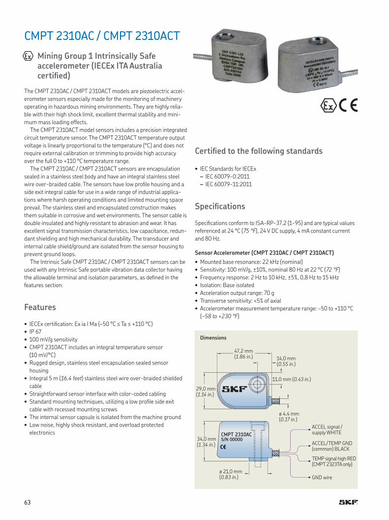
6363
CMPT 2310AC / CMPT 2310ACT
Mining Group 1 Intrinsically Safe accelerometer (IECEx ITA Australia certiied)
The CMPT 2310AC / CMPT 2310ACT models are piezoelectric accel-
erometer sensors especially made for the monitoring of machinery
operating in hazardous mining environments They are highly relia-
ble with their high shock limit, excellent thermal stability and mini-
mum mass loading effects
The CMPT 2310ACT model sensors includes a precision integrated
circuit temperature sensor The CMPT 2310ACT temperature output
voltage is linearly proportional to the temperature (°C) and does not
require external calibration or trimming to provide high accuracy
over the full 0 to +110 °C temperature range
The CMPT 2310AC / CMPT 2310ACT sensors are encapsulation
sealed in a stainless steel body and have an integral stainless steel
wire over-braided cable The sensors have low proile housing and a
side exit integral cable for use in a wide range of industrial applica-
tions where harsh operating conditions and limited mounting space
prevail The stainless steel and encapsulated construction makes
them suitable in corrosive and wet environments The sensor cable is
double insulated and highly resistant to abrasion and wear It has
excellent signal transmission characteristics, low capacitance, redun-
dant shielding and high mechanical durability The transducer and
internal cable shield/ground are isolated from the sensor housing to
prevent ground loops
The Intrinsic Safe CMPT 2310AC / CMPT 2310ACT sensors can be
used with any Intrinsic Safe portable vibration data collector having
the allowable terminal and isolation parameters, as deined in the
features section
Features
• IECEx certiication: Ex ia I Ma (–50 °C ≤ Ta ≤ +110 °C)
• IP 67
• 100 mV/g sensitivity
• CMPT 2310ACT includes an integral temperature sensor
(10 mV/°C)
• Rugged design, stainless steel encapsulation sealed sensor
housing
• Integral 5 m (16.4 feet) stainless steel wire over-braided shielded
cable
• Straightforward sensor interface with color-coded cabling
• Standard mounting techniques, utilizing a low proile side exit
cable with recessed mounting screws
• The internal sensor capsule is isolated from the machine ground
• Low noise, highly shock resistant, and overload protected
electronics
Certiied to the following standards
• IEC Standards for IECEx
– IEC 60079-0:2011
– IEC 60079-11:2011
Speciications
Speciications conform to ISA-RP-37 2 (1-95) and are typical values
referenced at 24 °C (75 °F), 24 V DC supply, 4 mA constant current
and 80 Hz
Sensor Accelerometer (CMPT 2310AC / CMPT 2310ACT)
• Mounted base resonance: 22 kHz (nominal)
• Sensitivity: 100 mV/g, ±10%, nominal 80 Hz at 22 °C (72 °F)
• Frequency response: 2 Hz to 10 kHz, ±5%, 0,8 Hz to 15 kHz
• Isolation: Base isolated
• Acceleration output range: 70 g
• Transverse sensitivity: <5% of axial
• Accelerometer measurement temperature range: –50 to +110 °C
(–58 to +230 °F)
CMPT 2310ACS/N 00000
Dimensions
47,2 mm (1.86 in.) 14,0 mm
(0.55 in.)
11,0 mm (0.43 in.)
ø 4,4 mm (0.17 in.)
29,0 mm (1.14 in.)
ø 21,0 mm (0.83 in.)
34,0 mm (1.34 in.)
ACCEL signal / supply WHITE
ACCEL/TEMP GND (common) BLACK
TEMP signal high RED (CMPT 2323TA only)
GND wire
6464
D
Ordering information
Standard sensor, 5 m (16.4 ft.) coniguration*Sensor with 5 m (16.4 ft.) integral cable, 1/4-28 and M6 x 1 socket head cap screws provided
CMPT 2310AC Sensor for mining industry, side exit and acceleration
CMPT 2310ACT Sensor for mining industry, side exit, acceleration and temperature
10 m (32.8 ft.) coniguration*Sensor with 10 m (32.8 ft.) integral cable, 1/4-28 and M6 x 1 socket head cap screws provided
CMPT 2310AC-10 Sensor for mining industry, side exit and acceleration
CMPT 2310ACT-10 Sensor for mining industry, side exit, acceleration and temperature
15 m (49.2 ft.) coniguration*Sensor with 15 m (49.2 ft.) integral cable, 1/4-28 and M6 x 1 socket head cap screws provided
CMPT 2310AC-15 Sensor for mining industry, side exit and acceleration
CMPT 2310ACT-15 Sensor for mining industry, side exit, acceleration and temperature
* Calibration sensitivity is provided for each accelerometer package with nominal sensitivity etched on each unit
Sensor – Temperature (CMPT 2310ACT)
• Sensitivity: 10 mV/°C
• Temperature sensor measurement range: 0 to +110 °C
(32 to +230 °F)
Electrical
• Power requirements:
– Voltage source: +24 V DC nominal, +18 to +30 V DC
– Constant current diode: 4 mA DC at +24 V DC, 2 to 10 mA is
permissible
• Acceleration sensor electrical noise: <1 mg RMS broadband 2,5 Hz
to 25,0 kHz
• Acceleration sensor bias output voltage: 11,5 V DC, ±10% for +24 V
DC supply at 25 °C (77 °F)
• Over-voltage protection: Approximately 18 V DC
• Reverse polarity (wiring) Protection
• Settling time: 2 seconds
• Output impedance: 200 Ohms maximum
• Case isolation: >108 Ohms at 500 V
Wire connections (CMPT 2310AC)
• White: ACCEL signal/power (connected to constant current source)
• Black: ACCEL signal ground (GND)
• Drain wire: Screen connected to internal shield (isolated from case)
Wire connections (CMPT 2310ACT)
• White: ACCEL signal/power (connected to constant current source)
• Black: ACCEL signal ground (GND)
• Red: Temperature signal high
• Drain wire: Screen connected to internal shield (isolated from case)
Environmental
• Storage temperature range: –50 to +110 °C (-58 to +230 °F)
• Vibration limit: 70 g peak
• Shock limit: 5 000 g
• Electromagnetic sensitivity, equivalent g, maximum: <100 µg/
gauss at 50 to 60 Hz
• Emissions: EN 61000-6-4:2001
• Immunity: EN 61000-6-2:1999
• CE: According to the generic immunity standard for Industrial Envi-
ronment EN 50082-2
– Acceptance criteria: The generated “false equivalent g level”
under the above test conditions should be less than 2 mg meas-
ured peak to peak
• IEC: 529, IP 67 (For climatic conditions, recommend to use conduit/
hose over braided cable )
Physical
• Dimensions: See drawing
• Weight: Sensor with cable 410 g (14.5 oz.)
• Case material: 304 stainless steel
• Sensing element/construction: PZT/Compression
• Mounting: M6 x 1 (30 mm long) and 1/4–28 UNF (1 25 in long)
socket head cap screws provided
• Mounting torque: 6 Nm (50 in. lbs.)
• Cable: Integral cable, 5 m (16.4 ft.)
• Wire speciication: 0,32 mm2 (AWG 22) stranded tin copper (seven
strands at 0,02 mm2 each)
Intrinsically Safe Requirements
• Cable: Integral cable, 5 m (16.4 ft.)
• Certiicate details: Group I
– IECEx ITA 13 0008X, Ex ia I Ma (–50 °C to +110 °C)
• Terminal parameters: Ui = 28 V, Ii = 93 mA, Pi = 0 65 W
• 500 V isolation: Units will pass a 500 V Isolation Test
• Equipment: The equipment must be returned to the manufacturer
for maintenance or replacement
– Address:
SKF Condition Monitoring Centre (Livingston) Ltd
2 Michaelson Square, Kirkton Campus,
Livingston, United Kingdom EH54 7DP
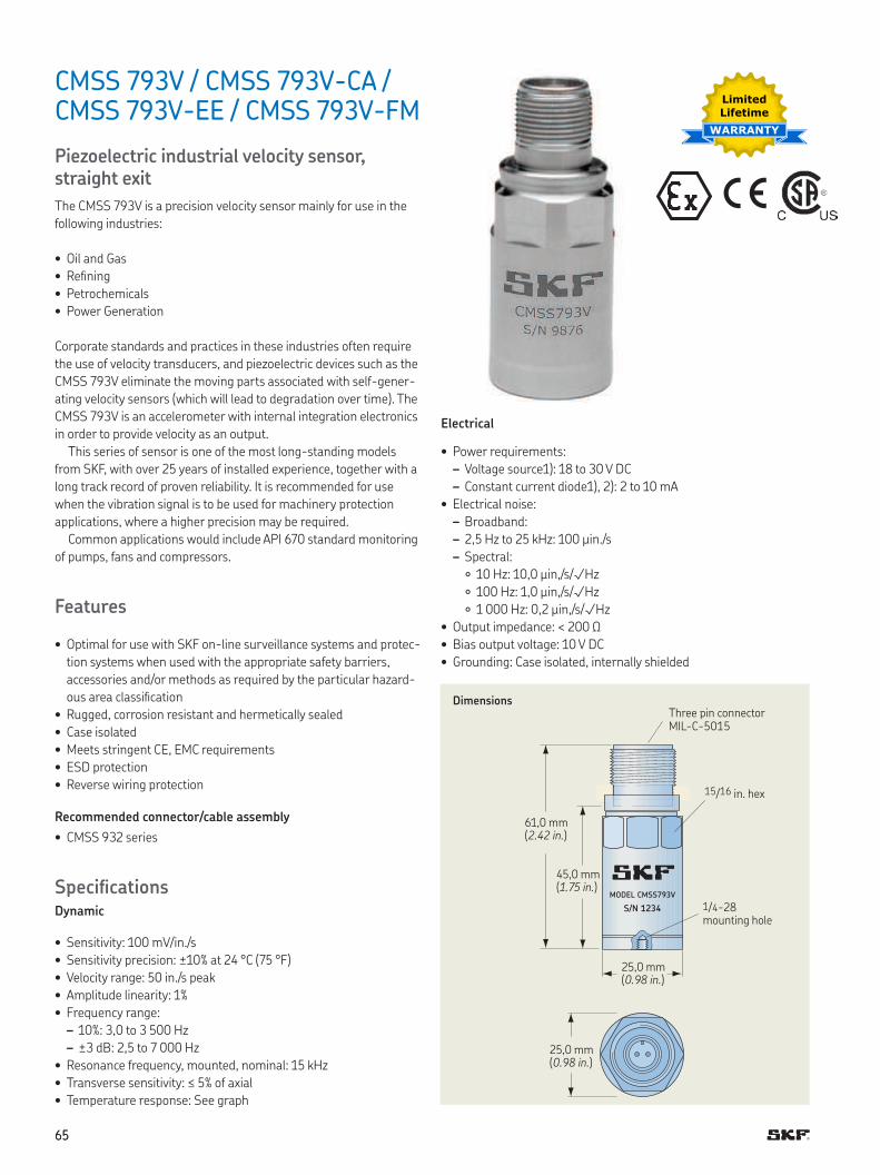
6565
CMSS 793V / CMSS 793V-CA / CMSS 793V-EE / CMSS 793V-FM
Piezoelectric industrial velocity sensor, straight exit
The CMSS 793V is a precision velocity sensor mainly for use in the
following industries:
• Oil and Gas
• Reining
• Petrochemicals
• Power Generation
Corporate standards and practices in these industries often require
the use of velocity transducers, and piezoelectric devices such as the
CMSS 793V eliminate the moving parts associated with self-gener-
ating velocity sensors (which will lead to degradation over time) The
CMSS 793V is an accelerometer with internal integration electronics
in order to provide velocity as an output
This series of sensor is one of the most long-standing models
from SKF, with over 25 years of installed experience, together with a
long track record of proven reliability It is recommended for use
when the vibration signal is to be used for machinery protection
applications, where a higher precision may be required
Common applications would include API 670 standard monitoring
of pumps, fans and compressors
Features
• Optimal for use with SKF on-line surveillance systems and protec-
tion systems when used with the appropriate safety barriers,
accessories and/or methods as required by the particular hazard-
ous area classiication
• Rugged, corrosion resistant and hermetically sealed
• Case isolated
• Meets stringent CE, EMC requirements
• ESD protection
• Reverse wiring protection
Recommended connector/cable assembly
• CMSS 932 series
SpeciicationsDynamic
• Sensitivity: 100 mV/in /s
• Sensitivity precision: ±10% at 24 °C (75 °F)
• Velocity range: 50 in /s peak
• Amplitude linearity: 1%
• Frequency range:
– 10%: 3,0 to 3 500 Hz
– ±3 dB: 2,5 to 7 000 Hz
• Resonance frequency, mounted, nominal: 15 kHz
• Transverse sensitivity: ≤ 5% of axial
• Temperature response: See graph
MODEL CMSS793V
S/N 1234
DimensionsThree pin connector MIL-C-5015
61,0 mm (2.42 in.)
45,0 mm (1.75 in.)
25,0 mm (0.98 in.)
25,0 mm (0.98 in.)
1/4-28 mounting hole
15/16 in hex
Electrical
• Power requirements:
– Voltage source1): 18 to 30 V DC
– Constant current diode1), 2): 2 to 10 mA
• Electrical noise:
– Broadband:
– 2,5 Hz to 25 kHz: 100 µin /s
– Spectral:
10 Hz: 10,0 µin,/s/√Hz
100 Hz: 1,0 µin,/s/√Hz
1 000 Hz: 0,2 µin,/s/√Hz
• Output impedance: < 200 Ω
• Bias output voltage: 10 V DC
• Grounding: Case isolated, internally shielded
Limited
Lifetime
WARRANTY
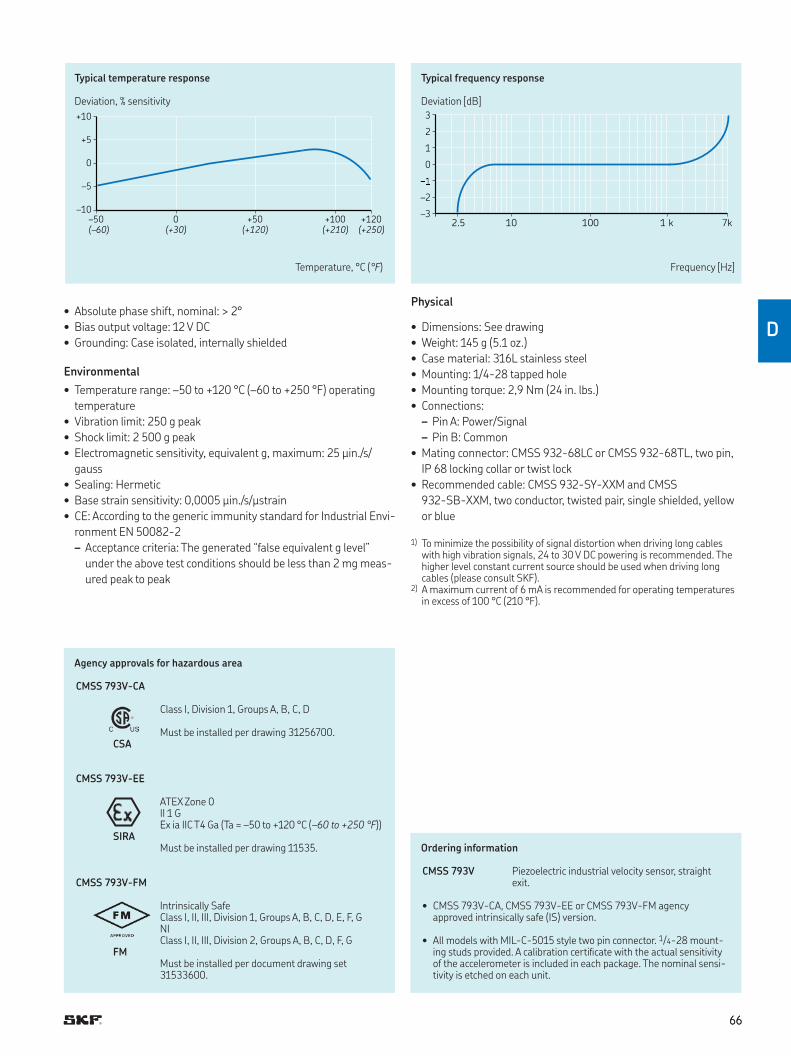
6666
D
3
2
1
0
–2
–32.5 10 100 1 k 7k
+10
+5
0
–5
–10
–50 0 +50 +100 +120
(–60) (+30) (+120) (+210) (+250)
Typical temperature response
Deviation, % sensitivity
Typical frequency response
Deviation [dB]
Temperature, °C (°F) Frequency [Hz]
Ordering information
CMSS 793V Piezoelectric industrial velocity sensor, straight exit
• CMSS 793V-CA, CMSS 793V-EE or CMSS 793V-FM agency approved intrinsically safe (IS) version
• All models with MIL-C-5015 style two pin connector 1/4-28 mount-ing studs provided A calibration certiicate with the actual sensitivity of the accelerometer is included in each package The nominal sensi-tivity is etched on each unit
Physical
• Dimensions: See drawing
• Weight: 145 g (5 1 oz )
• Case material: 316L stainless steel
• Mounting: 1/4-28 tapped hole
• Mounting torque: 2,9 Nm (24 in lbs )
• Connections:
– Pin A: Power/Signal
– Pin B: Common
• Mating connector: CMSS 932-68LC or CMSS 932-68TL, two pin,
IP 68 locking collar or twist lock
• Recommended cable: CMSS 932-SY-XXM and CMSS
932-SB-XXM, two conductor, twisted pair, single shielded, yellow
or blue
1) To minimize the possibility of signal distortion when driving long cables with high vibration signals, 24 to 30 V DC powering is recommended The higher level constant current source should be used when driving long cables (please consult SKF)
2) A maximum current of 6 mA is recommended for operating temperatures in excess of 100 °C (210 °F)
Agency approvals for hazardous area
CMSS 793V-CA
Class I, Division 1, Groups A, B, C, D
Must be installed per drawing 31256700 CSA
CMSS 793V-EE
ATEX Zone 0II 1 GEx ia IIC T4 Ga (Ta = –50 to +120 °C (–60 to +250 °F))
SIRAMust be installed per drawing 11535
CMSS 793V-FM
Intrinsically SafeClass I, II, III, Division 1, Groups A, B, C, D, E, F, GNIClass I, II, III, Division 2, Groups A, B, C, D, F, G
FMMust be installed per document drawing set 31533600
• Absolute phase shift, nominal: > 2°
• Bias output voltage: 12 V DC
• Grounding: Case isolated, internally shielded
Environmental
• Temperature range: –50 to +120 °C (–60 to +250 °F) operating
temperature
• Vibration limit: 250 g peak
• Shock limit: 2 500 g peak
• Electromagnetic sensitivity, equivalent g, maximum: 25 µin /s/
gauss
• Sealing: Hermetic
• Base strain sensitivity: 0,0005 µin /s/µstrain
• CE: According to the generic immunity standard for Industrial Envi-
ronment EN 50082-2
– Acceptance criteria: The generated “false equivalent g level”
under the above test conditions should be less than 2 mg meas-
ured peak to peak
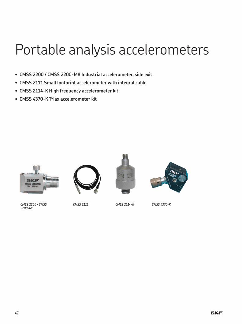
6767
Portable analysis accelerometers
• CMSS 2200 / CMSS 2200-M8 Industrial accelerometer, side exit
• CMSS 2111 Small footprint accelerometer with integral cable
• CMSS 2114-K High frequency accelerometer kit
• CMSS 4370-K Triax accelerometer kit
CMSS 2200 / CMSS 2200-M8
CMSS 2114-KCMSS 2111 CMSS 4370-K
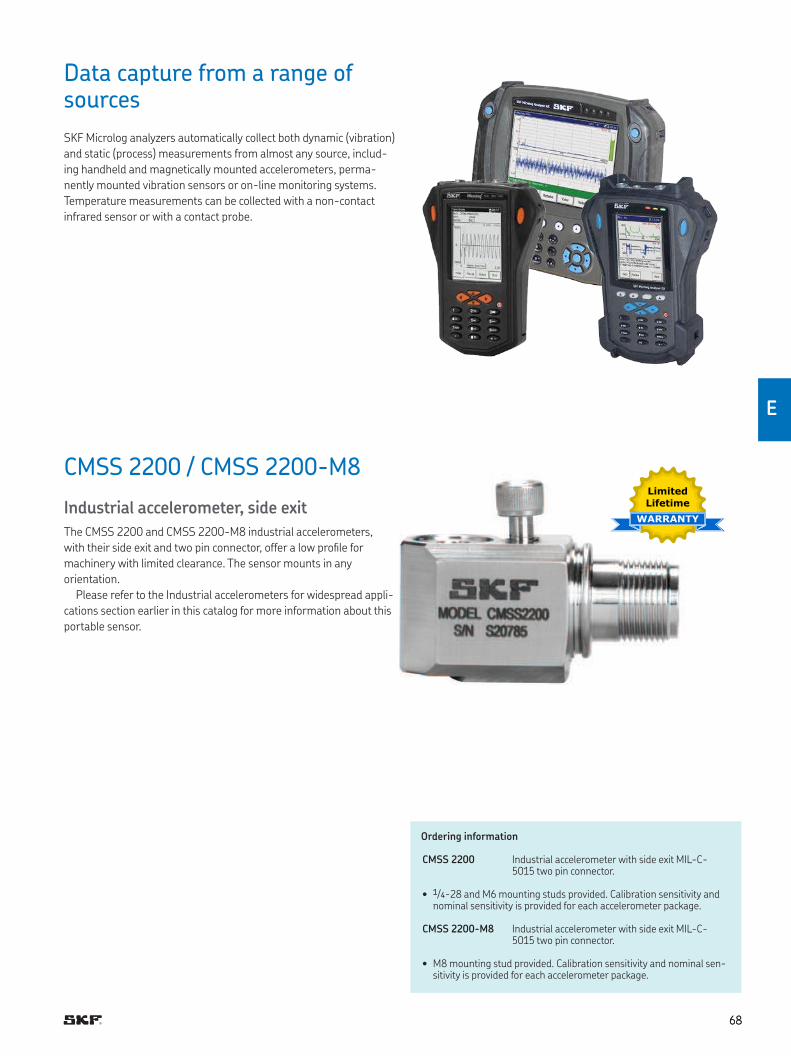
6868
E
Data capture from a range of sources
SKF Microlog analyzers automatically collect both dynamic (vibration)
and static (process) measurements from almost any source, includ-
ing handheld and magnetically mounted accelerometers, perma-
nently mounted vibration sensors or on-line monitoring systems
Temperature measurements can be collected with a non-contact
infrared sensor or with a contact probe
CMSS 2200 / CMSS 2200-M8
Industrial accelerometer, side exit
The CMSS 2200 and CMSS 2200-M8 industrial accelerometers,
with their side exit and two pin connector, offer a low proile for
machinery with limited clearance The sensor mounts in any
orientation
Please refer to the Industrial accelerometers for widespread appli-
cations section earlier in this catalog for more information about this
portable sensor
Ordering information
CMSS 2200 Industrial accelerometer with side exit MIL-C-5015 two pin connector
• 1/4-28 and M6 mounting studs provided Calibration sensitivity and nominal sensitivity is provided for each accelerometer package
CMSS 2200-M8 Industrial accelerometer with side exit MIL-C-5015 two pin connector
• M8 mounting stud provided Calibration sensitivity and nominal sen-sitivity is provided for each accelerometer package
Limited
Lifetime
WARRANTY
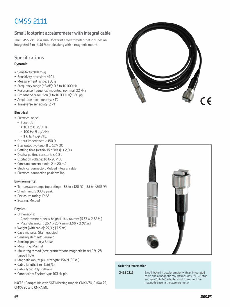
6969
CMSS 2111
Small footprint accelerometer with integral cable
The CMSS 2111 is a small footprint accelerometer that includes an
integrated 2 m (6.56 ft.) cable along with a magnetic mount
SpeciicationsDynamic
• Sensitivity: 100 mVg
• Sensitivity precision: ±10%
• Measurement range: ±50 g
• Frequency range (±3 dB): 0,5 to 10 000 Hz
• Resonance frequency, mounted, nominal: 22 kHz
• Broadband resolution (1 to 10 000 Hz): 350 μg
• Amplitude non-linearity: ±1%
• Transverse sensitivity: ≤ 7%
Electrical
• Electrical noise:
– Spectral:
10 Hz: 8 μg/√Hz
100 Hz: 5 μg/√Hz
1 kHz: 4 μg/√Hz
• Output impedance: < 150 Ω
• Bias output voltage: 8 to 12 V DC
• Settling time (within 1% of bias): ≤ 2,0 s
• Discharge time constant: ≤ 0,3 s
• Excitation voltage: 18 to 28 V DC
• Constant current diode: 2 to 20 mA
• Electrical connector: Molded integral cable
• Electrical connection position: Top
Environmental
• Temperature range (operating): –55 to +120 °C (–65 to +250 °F)
• Shock limit: 5 000 g peak
• Enclosure rating: IP 68
• Sealing: Molded
Physical
• Dimensions:
– Accelerometer (hex × height): 14 × 64 mm (0.55 × 2.52 in )
– Magnetic mount: 25,4 × 25,9 mm (1.00 × 1.02 in.)
• Weight (with cable): 99,3 g (3.5 oz.)
• Case material: Stainless steel
• Sensing element: Ceramic
• Sensing geometry: Shear
• Mounting: Magnet
• Mounting thread (accelerometer and magnetic base): 1/4-28
tapped hole
• Magnetic mount pull strength: 156 N (35 lb.)
• Cable length: 2 m (6.56 ft.)
• Cable type: Polyurethane
• Connection: Fischer type 103 six pin
NOTE: Compatible with SKF Microlog models CMXA 70, CMXA 75,
CMXA 80 and CMXA 50
Ordering information
CMSS 2111 Small footprint accelerometer with an integrated cable and a magnetic mount; includes 1/4–28 stud and 1/4–28 to M6 adapter stud to connect the magnetic base to the accelerometer
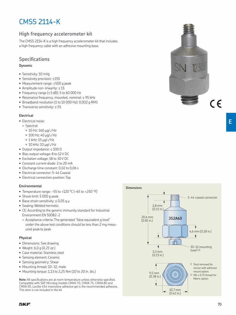
7070
E
CMSS 2114-K
High frequency accelerometer kit
The CMSS 2114-K is a high frequency accelerometer kit that includes
a high frequency cable with an adhesive mounting base
SpeciicationsDynamic
• Sensitivity: 10 mVg
• Sensitivity precision: ±15%
• Measurement range: ±500 g peak
• Amplitude non-linearity: ≤ 1%
• Frequency range (±3 dB): 5 to 60 000 Hz
• Resonance frequency, mounted, nominal: ≥ 95 kHz
• Broadband resolution (1 to 10 000 Hz): 0,002 g RMS
• Transverse sensitivity: ≤ 5%
Electrical
• Electrical noise:
– Spectral:
10 Hz: 160 μg/√Hz
100 Hz: 40 μg/√Hz
1 kHz: 15 μg/√Hz
10 kHz: 10 μg/√Hz
• Output impedance: ≤ 100 Ω
• Bias output voltage: 8 to 12 V DC
• Excitation voltage: 18 to 30 V DC
• Constant current diode: 2 to 20 mA
• Discharge time constant: 0,02 to 0,06 s
• Electrical connector: 5-44 Coaxial
• Electrical connection position: Top
Environmental
• Temperature range: –55 to +120 °C (–65 to +250 °F)
• Shock limit: 5 000 g peak
• Base strain sensitivity: ≤ 0,05 g μ
• Sealing: Welded hermetic
• CE: According to the generic immunity standard for Industrial
Environment EN 50082-2
– Acceptance criteria: The generated “false equivalent g level”
under the above test conditions should be less than 2 mg meas-
ured peak to peak
Physical
• Dimensions: See drawing
• Weight: 6,0 g (0.21 oz.)
• Case material: Stainless steel
• Sensing element: Ceramic
• Sensing geometry: Shear
• Mounting thread: 10-32, male
• Mounting torque: 1,13 to 2,25 Nm (10 to 20 in. lbs.)
Note: All speciications are at room temperature unless otherwise speciied. Compatible with SKF Microlog models CMXA 70, CMXA 75, CMXA 80 and CMXA 50. Loctite 454 insensitive adhesive gel is the recommended adhesive. This item is not included in the kit
352A60
Dimensions
5-44 coaxial connector
4,6 mm (0.18 in.)
2,8 mm (0.11 in.)
20,6 mm (0.81 in.)
3,3 mm (0.13 in.)
10,7 mm (0.42 in.)
9,5 mm (0.38 in.)
10-32 mounting hole1) 2)
1) Stud removed for
sensor with adhesive
mount option 2) M6 × 0,75 thread for
Metric option
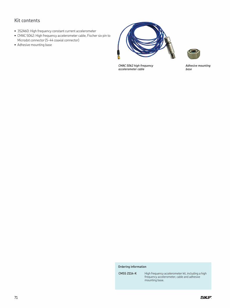
7171
Kit contents
• 352A60: High frequency constant current accelerometer
• CMAC 5062: High frequency accelerometer cable, Fischer six pin to
Microdot connector (5-44 coaxial connector)
• Adhesive mounting base
Ordering information
CMSS 2114-K High frequency accelerometer kit, including a high frequency accelerometer, cable and adhesive mounting base
CMAC 5062 high frequency accelerometer cable
Adhesive mounting base
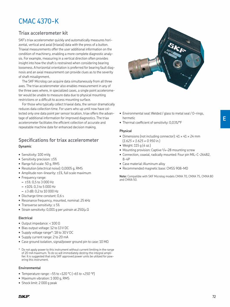
7272
E
CMAC 4370-K
Triax accelerometer kit
SKF’s triax accelerometer quickly and automatically measures hori-
zontal, vertical and axial (triaxial) data with the press of a button
Triaxial measurements offer the user additional information on the
condition of machinery, enabling a more complete diagnostic analy-
sis For example, measuring in a vertical direction often provides
insight into how the shaft is restrained when considering bearing
looseness A horizontal orientation is preferred for bearing fault diag-
nosis and an axial measurement can provide clues as to the severity
of shaft misalignment
The SKF Microlog can acquire data simultaneously from all three
axes The triax accelerometer also enables measurement in any of
the three axes where, in specialized cases, a single point accelerome-
ter would be unable to measure data due to physical mounting
restrictions or a dificult to access mounting surface
For those who typically collect triaxial data, the sensor dramatically
reduces data collection time For users who up until now have col-
lected only one data point per sensor location, triax offers the advan-
tage of additional information for improved diagnostics The triax
accelerometer facilitates the eficient collection of accurate and
repeatable machine date for enhanced decision making
Speciications for triax accelerometerDynamic
• Sensitivity: 100 mVg
• Sensitivity precision: ±5%
• Range full scale: 50 g, RMS
• Resolution (electrical noise): 0,0005 g, RMS
• Amplitude non-linearity: ±1%, full scale maximum
• Frequency range:
– ±5%: 0,5 to 3 000 Hz
– ±10%: 0,3 to 5 000 Hz
– ±3 dB: 0,2 to 10 000 Hz
• Discharge time constant: 0,6 s
• Resonance frequency, mounted, nominal: 25 kHz
• Transverse sensitivity: ≤ 5%
• Strain sensitivity: 0,001 g per µstrain at 250/μ Ω
Electrical
• Output impedance: < 100 Ω
• Bias output voltage: 12 to 13 V DC
• Supply voltage range*: 18 to 30 V DC
• Supply current range: 2 to 20 mA
• Case ground isolation, signal/power ground pin to case: 10 MΩ
* Do not apply power to this instrument without current limiting in the range of 20 mA maximum To do so will immediately destroy the integral ampli-ier It is suggested that only SKF approved power units be utilized for pow-ering this instrument
Environmental
• Temperature range: –55 to +120 °C (–65 to +250 °F)
• Maximum vibration: 1 000 g, RMS
• Shock limit: 2 000 g peak
• Environmental seal: Welded / glass to metal seal / O-rings,
hermetic
• Thermal coeficient of sensitivity: 0,03%/°F
Physical
• Dimensions (not including connector): 41 × 41 × 24 mm
(1.625 × 1.625 × 0.950 in.)
• Weight: 115 g (4 oz.)
• Mounting provision: Captive 1/4–28 mounting screw
• Connection, coaxial, radically mounted: Four pin MIL-C-26482,
8-4P
• Case material: Aluminum alloy
• Recommended magnetic base: CMSS 908-MD
Note: Compatible with SKF Microlog models CMXA 70, CMXA 75, CMXA 80 and CMXA 50.
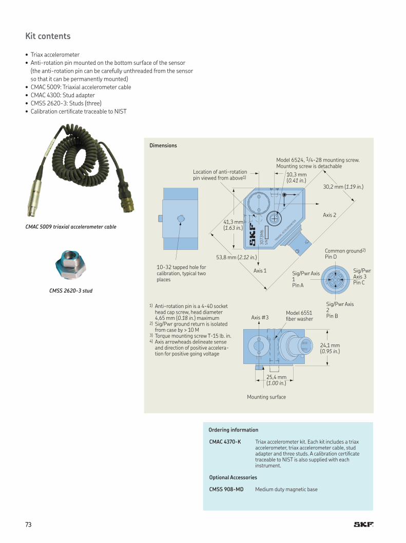
7373
Kit contents
• Triax accelerometer
• Anti-rotation pin mounted on the bottom surface of the sensor
(the anti-rotation pin can be carefully unthreaded from the sensor
so that it can be permanently mounted)
• CMAC 5009: Triaxial accelerometer cable
• CMAC 4300: Stud adapter
• CMSS 2620-3: Studs (three)
• Calibration certiicate traceable to NIST
Ordering information
CMAC 4370-K Triax accelerometer kit Each kit includes a triax accelerometer, triax accelerometer cable, stud adapter and three studs A calibration certiicate traceable to NIST is also supplied with each instrument
Optional Accessories
CMSS 908-MD Medium duty magnetic base
CMAC 5009 triaxial accelerometer cable
CMSS 2620-3 stud
TRIAXIAL
ACC
ELER
OMET
ER
3073M
6S/N
3
1
2
Dimensions
Model 6524, 1/4-28 mounting screw. Mounting screw is detachable
10-32 tapped hole for calibration, typical two places
Location of anti-rotation pin viewed from above1)
Mounting surface
Common ground2)
Pin D53,8 mm (2.12 in.)
Sig/Pwr Axis 3 Pin C
10,3 mm (0.41 in.)
30,2 mm (1.19 in.)
Axis 241,3 mm (1.63 in.)
Axis #3
Axis 1
25,4 mm (1.00 in.)
24,1 mm (0.95 in.)
Sig/Pwr Axis 2 Pin B
Model 6551 iber washer
Sig/Pwr Axis 1 Pin A
1) Anti-rotation pin is a 4-40 socket head cap screw, head diameter 4,65 mm (0.18 in.) maximum
2) Sig/Pwr ground return is isolated from case by > 10 M
3) Torque mounting screw T-15 lb in 4) Axis arrowheads delineate sense
and direction of positive accelera-tion for positive going voltage
7474
F
Special purpose sensors
Low frequency accelerometers• CMSS 793L Low frequency accelerometer, straight exit
• CMSS 797L Low frequency industrial accelerometer, ring mode, side exit
CMSS 793L CMSS 797L
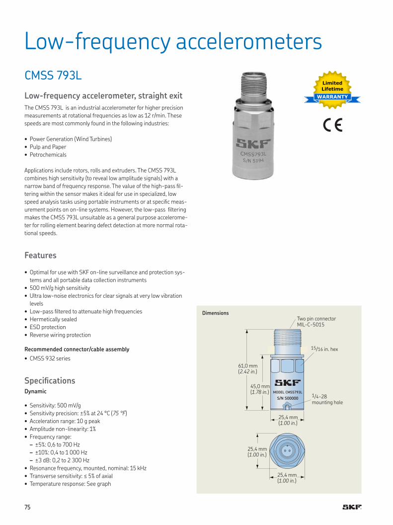
7575
CMSS 793L
Low-frequency accelerometer, straight exit
The CMSS 793L is an industrial accelerometer for higher precision
measurements at rotational frequencies as low as 12 r/min These
speeds are most commonly found in the following industries:
• Power Generation (Wind Turbines)
• Pulp and Paper
• Petrochemicals
Applications include rotors, rolls and extruders The CMSS 793L
combines high sensitivity (to reveal low amplitude signals) with a
narrow band of frequency response The value of the high-pass il-
tering within the sensor makes it ideal for use in specialized, low
speed analysis tasks using portable instruments or at speciic meas-
urement points on on-line systems However, the low-pass iltering
makes the CMSS 793L unsuitable as a general purpose accelerome-
ter for rolling element bearing defect detection at more normal rota-
tional speeds
Features
• Optimal for use with SKF on-line surveillance and protection sys-
tems and all portable data collection instruments
• 500 mV/g high sensitivity
• Ultra low-noise electronics for clear signals at very low vibration
levels
• Low-pass iltered to attenuate high frequencies
• Hermetically sealed
• ESD protection
• Reverse wiring protection
Recommended connector/cable assembly
• CMSS 932 series
SpeciicationsDynamic
• Sensitivity: 500 mV/g
• Sensitivity precision: ±5% at 24 °C (75 °F)
• Acceleration range: 10 g peak
• Amplitude non-linearity: 1%
• Frequency range:
– ±5%: 0,6 to 700 Hz
– ±10%: 0,4 to 1 000 Hz
– ±3 dB: 0,2 to 2 300 Hz
• Resonance frequency, mounted, nominal: 15 kHz
• Transverse sensitivity: ≤ 5% of axial
• Temperature response: See graph
MODEL CMSS793L
S/N S00000
DimensionsTwo pin connectorMIL-C-5015
15/16 in hex
61,0 mm (2.42 in.)
25,4 mm (1.00 in.)
45,0 mm (1.78 in.)
25,4 mm (1.00 in.)
25,4 mm (1.00 in.)
1/4-28 mounting hole
Low-frequency accelerometers
Limited
Lifetime
WARRANTY
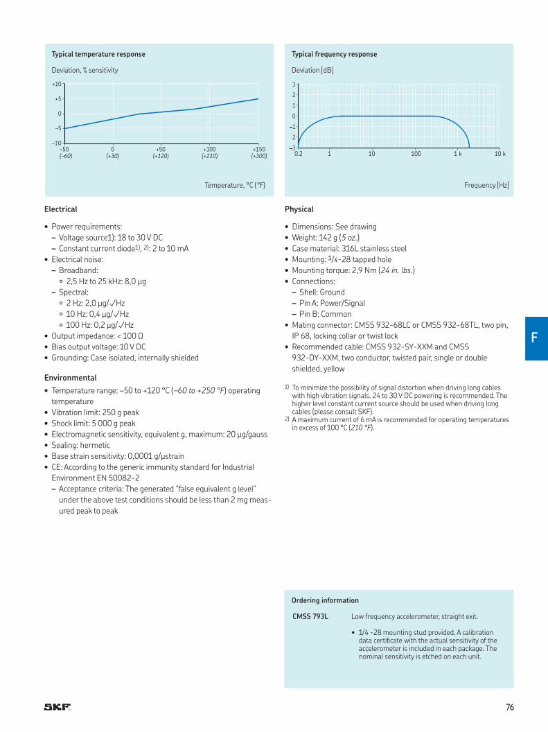
7676
F
3
2
1
0
1
2
30.2 1 10 100 1 k 10 k
+10
+5
0
–5
–10
–50 0 +50 +100 +150
(–60) (+30) (+120) (+210) (+300)
Typical temperature response
Deviation, % sensitivity
Typical frequency response
Deviation [dB]
Temperature, °C (°F) Frequency [Hz]
Electrical
• Power requirements:
– Voltage source1): 18 to 30 V DC
– Constant current diode1), 2): 2 to 10 mA
• Electrical noise:
– Broadband:
2,5 Hz to 25 kHz: 8,0 µg
– Spectral:
2 Hz: 2,0 µg/√Hz
10 Hz: 0,4 µg/√Hz
100 Hz: 0,2 µg/√Hz
• Output impedance: < 100 Ω
• Bias output voltage: 10 V DC
• Grounding: Case isolated, internally shielded
Environmental
• Temperature range: –50 to +120 °C (–60 to +250 °F) operating
temperature
• Vibration limit: 250 g peak
• Shock limit: 5 000 g peak
• Electromagnetic sensitivity, equivalent g, maximum: 20 µg/gauss
• Sealing: hermetic
• Base strain sensitivity: 0,0001 g/µstrain
• CE: According to the generic immunity standard for Industrial
Environment EN 50082-2
– Acceptance criteria: The generated “false equivalent g level”
under the above test conditions should be less than 2 mg meas-
ured peak to peak
Ordering information
CMSS 793L Low frequency accelerometer, straight exit
• 1/4 -28 mounting stud provided A calibration data certiicate with the actual sensitivity of the accelerometer is included in each package The nominal sensitivity is etched on each unit
Physical
• Dimensions: See drawing
• Weight: 142 g (5 oz.)
• Case material: 316L stainless steel
• Mounting: 1/4-28 tapped hole
• Mounting torque: 2,9 Nm (24 in. lbs.)
• Connections:
– Shell: Ground
– Pin A: Power/Signal
– Pin B: Common
• Mating connector: CMSS 932-68LC or CMSS 932-68TL, two pin,
IP 68, locking collar or twist lock
• Recommended cable: CMSS 932-SY-XXM and CMSS
932-DY-XXM, two conductor, twisted pair, single or double
shielded, yellow
1) To minimize the possibility of signal distortion when driving long cables with high vibration signals, 24 to 30 V DC powering is recommended The higher level constant current source should be used when driving long cables (please consult SKF)
2) A maximum current of 6 mA is recommended for operating temperatures in excess of 100 °C (210 °F)
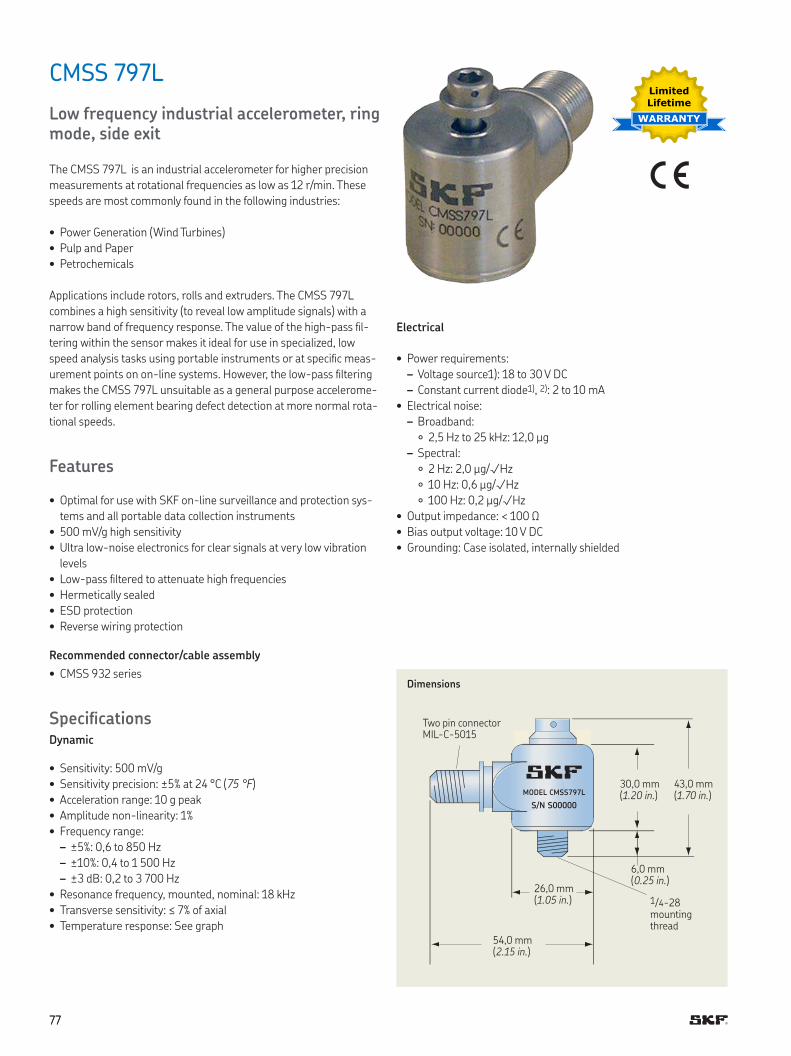
7777
CMSS 797L
Low frequency industrial accelerometer, ring mode, side exit
The CMSS 797L is an industrial accelerometer for higher precision
measurements at rotational frequencies as low as 12 r/min These
speeds are most commonly found in the following industries:
• Power Generation (Wind Turbines)
• Pulp and Paper
• Petrochemicals
Applications include rotors, rolls and extruders The CMSS 797L
combines a high sensitivity (to reveal low amplitude signals) with a
narrow band of frequency response The value of the high-pass il-
tering within the sensor makes it ideal for use in specialized, low
speed analysis tasks using portable instruments or at speciic meas-
urement points on on-line systems However, the low-pass iltering
makes the CMSS 797L unsuitable as a general purpose accelerome-
ter for rolling element bearing defect detection at more normal rota-
tional speeds
Features
• Optimal for use with SKF on-line surveillance and protection sys-
tems and all portable data collection instruments
• 500 mV/g high sensitivity
• Ultra low-noise electronics for clear signals at very low vibration
levels
• Low-pass iltered to attenuate high frequencies
• Hermetically sealed
• ESD protection
• Reverse wiring protection
Recommended connector/cable assembly
• CMSS 932 series
SpeciicationsDynamic
• Sensitivity: 500 mV/g
• Sensitivity precision: ±5% at 24 °C (75 °F)
• Acceleration range: 10 g peak
• Amplitude non-linearity: 1%
• Frequency range:
– ±5%: 0,6 to 850 Hz
– ±10%: 0,4 to 1 500 Hz
– ±3 dB: 0,2 to 3 700 Hz
• Resonance frequency, mounted, nominal: 18 kHz
• Transverse sensitivity: ≤ 7% of axial
• Temperature response: See graph
MODEL CMSS797L
S/N S00000
Dimensions
1/4-28 mounting thread
30,0 mm (1.20 in.)
6,0 mm (0.25 in.)
43,0 mm (1.70 in.)
Two pin connector MIL-C-5015
54,0 mm (2.15 in.)
26,0 mm (1.05 in.)
Electrical
• Power requirements:
– Voltage source1): 18 to 30 V DC
– Constant current diode1), 2): 2 to 10 mA
• Electrical noise:
– Broadband:
2,5 Hz to 25 kHz: 12,0 µg
– Spectral:
2 Hz: 2,0 µg/√Hz
10 Hz: 0,6 µg/√Hz
100 Hz: 0,2 µg/√Hz
• Output impedance: < 100 Ω
• Bias output voltage: 10 V DC
• Grounding: Case isolated, internally shielded
Limited
Lifetime
WARRANTY
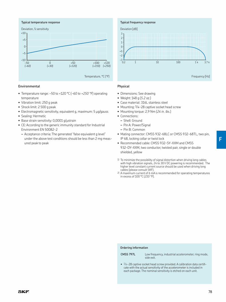
7878
F
3
2
1
0
–2
–30.2 1 10 100 1 k 3.7 k
+10
+5
0
–5
–10
–50 0 +50 +100 +120
(–60) (+30) (+120) (+210) (+250)
Typical temperature response
Deviation, % sensitivity
Typical frequency response
Deviation [dB]
Temperature, °C (°F) Frequency [Hz]
Environmental
• Temperature range: –50 to +120 °C (–60 to +250 °F) operating
temperature
• Vibration limit: 250 g peak
• Shock limit: 2 500 g peak
• Electromagnetic sensitivity, equivalent g, maximum: 5 µg/gauss
• Sealing: Hermetic
• Base strain sensitivity: 0,0001 g/µstrain
• CE: According to the generic immunity standard for Industrial
Environment EN 50082-2
– Acceptance criteria: The generated “false equivalent g level”
under the above test conditions should be less than 2 mg meas-
ured peak to peak
Ordering information
CMSS 797L Low frequency, industrial accelerometer, ring mode, side exit
• 1/4-28 captive socket head screw provided A calibration data certii-cate with the actual sensitivity of the accelerometer is included in each package The nominal sensitivity is etched on each unit
Physical
• Dimensions: See drawing
• Weight: 148 g (5.2 oz.)
• Case material: 316L stainless steel
• Mounting: 1/4-28 captive socket head screw
• Mounting torque: 2,9 Nm (24 in. lbs.)
• Connections:
– Shell: Ground
– Pin A: Power/Signal
– Pin B: Common
• Mating connector: CMSS 932-68LC or CMSS 932-68TL, two pin,
IP 68, locking collar or twist lock
• Recommended cable: CMSS 932-SY-XXM and CMSS
932-DY-XXM, two conductor, twisted pair, single or double
shielded, yellow
1) To minimize the possibility of signal distortion when driving long cables with high vibration signals, 24 to 30 V DC powering is recommended The higher level constant current source should be used when driving long cables (please consult SKF)
2) A maximum current of 6 mA is recommended for operating temperatures in excess of 100 °C (210 °F)
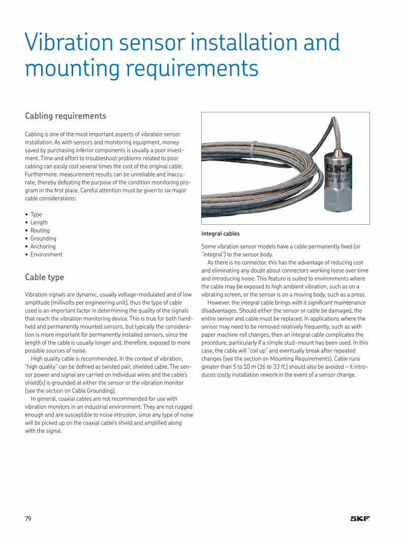
7979
Cabling requirements
Cabling is one of the most important aspects of vibration sensor
installation As with sensors and monitoring equipment, money
saved by purchasing inferior components is usually a poor invest-
ment Time and effort to troubleshoot problems related to poor
cabling can easily cost several times the cost of the original cable
Furthermore, measurement results can be unreliable and inaccu-
rate, thereby defeating the purpose of the condition monitoring pro-
gram in the irst place Careful attention must be given to six major
cable considerations:
• Type
• Length
• Routing
• Grounding
• Anchoring
• Environment
Cable type
Vibration signals are dynamic, usually voltage-modulated and of low
amplitude (millivolts per engineering unit), thus the type of cable
used is an important factor in determining the quality of the signals
that reach the vibration monitoring device This is true for both hand-
held and permanently mounted sensors, but typically the considera-
tion is more important for permanently installed sensors, since the
length of the cable is usually longer and, therefore, exposed to more
possible sources of noise
High quality cable is recommended In the context of vibration,
“high quality” can be deined as twisted pair, shielded cable The sen-
sor power and signal are carried on individual wires and the cable’s
shield(s) is grounded at either the sensor or the vibration monitor
(see the section on Cable Grounding)
In general, coaxial cables are not recommended for use with
vibration monitors in an industrial environment They are not rugged
enough and are susceptible to noise intrusion, since any type of noise
will be picked up on the coaxial cable’s shield and ampliied along
with the signal
Vibration sensor installation and mounting requirements
Integral cables
Some vibration sensor models have a cable permanently ixed (or
“integral”) to the sensor body
As there is no connector, this has the advantage of reducing cost
and eliminating any doubt about connectors working loose over time
and introducing noise This feature is suited to environments where
the cable may be exposed to high ambient vibration, such as on a
vibrating screen, or the sensor is on a moving body, such as a press
However, the integral cable brings with it signiicant maintenance
disadvantages Should either the sensor or cable be damaged, the
entire sensor and cable must be replaced In applications where the
sensor may need to be removed relatively frequently, such as with
paper machine roll changes, then an integral cable complicates the
procedure, particularly if a simple stud-mount has been used In this
case, the cable will “coil up” and eventually break after repeated
changes (see the section on Mounting Requirements) Cable runs
greater than 5 to 10 m (16 to 33 ft.) should also be avoided – it intro-
duces costly installation rework in the event of a sensor change
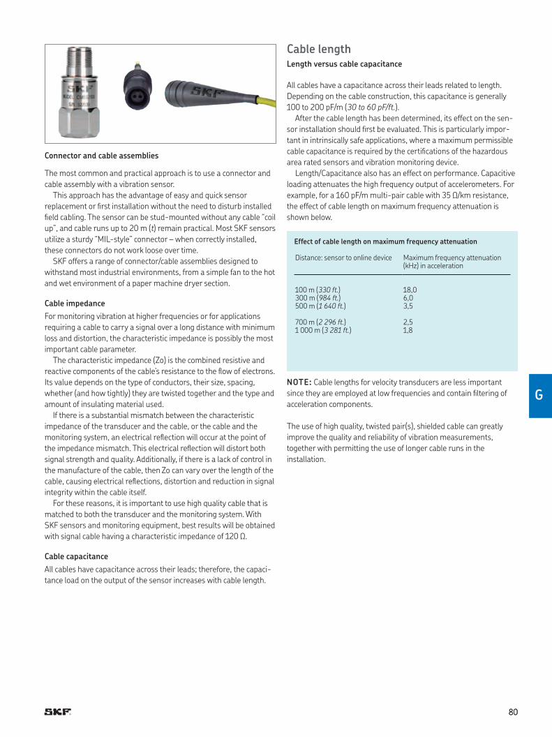
8080
G
Cable lengthLength versus cable capacitance
All cables have a capacitance across their leads related to length
Depending on the cable construction, this capacitance is generally
100 to 200 pF/m (30 to 60 pF/ft.)
After the cable length has been determined, its effect on the sen-
sor installation should irst be evaluated This is particularly impor-
tant in intrinsically safe applications, where a maximum permissible
cable capacitance is required by the certiications of the hazardous
area rated sensors and vibration monitoring device
Length/Capacitance also has an effect on performance Capacitive
loading attenuates the high frequency output of accelerometers For
example, for a 160 pF/m multi-pair cable with 35 Ω/km resistance,
the effect of cable length on maximum frequency attenuation is
shown below
Effect of cable length on maximum frequency attenuation
Distance: sensor to online device Maximum frequency attenuation (kHz) in acceleration
100 m (330 ft.) 18,0300 m (984 ft.) 6,0500 m (1 640 ft.) 3,5
700 m (2 296 ft.) 2,51 000 m (3 281 ft.) 1,8
NOTE: Cable lengths for velocity transducers are less important
since they are employed at low frequencies and contain iltering of
acceleration components
The use of high quality, twisted pair(s), shielded cable can greatly
improve the quality and reliability of vibration measurements,
together with permitting the use of longer cable runs in the
installation
Connector and cable assemblies
The most common and practical approach is to use a connector and
cable assembly with a vibration sensor
This approach has the advantage of easy and quick sensor
replacement or irst installation without the need to disturb installed
ield cabling The sensor can be stud-mounted without any cable “coil
up”, and cable runs up to 20 m (t) remain practical Most SKF sensors
utilize a sturdy “MIL-style” connector – when correctly installed,
these connectors do not work loose over time
SKF offers a range of connector/cable assemblies designed to
withstand most industrial environments, from a simple fan to the hot
and wet environment of a paper machine dryer section
Cable impedance
For monitoring vibration at higher frequencies or for applications
requiring a cable to carry a signal over a long distance with minimum
loss and distortion, the characteristic impedance is possibly the most
important cable parameter
The characteristic impedance (Zo) is the combined resistive and
reactive components of the cable’s resistance to the low of electrons
Its value depends on the type of conductors, their size, spacing,
whether (and how tightly) they are twisted together and the type and
amount of insulating material used
If there is a substantial mismatch between the characteristic
impedance of the transducer and the cable, or the cable and the
monitoring system, an electrical relection will occur at the point of
the impedance mismatch This electrical relection will distort both
signal strength and quality Additionally, if there is a lack of control in
the manufacture of the cable, then Zo can vary over the length of the
cable, causing electrical relections, distortion and reduction in signal
integrity within the cable itself
For these reasons, it is important to use high quality cable that is
matched to both the transducer and the monitoring system With
SKF sensors and monitoring equipment, best results will be obtained
with signal cable having a characteristic impedance of 120 Ω
Cable capacitance
All cables have capacitance across their leads; therefore, the capaci-
tance load on the output of the sensor increases with cable length
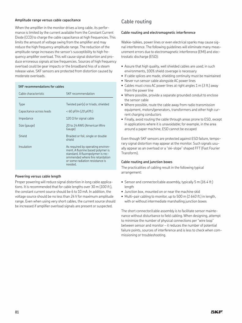
8181
Amplitude range versus cable capacitance
When the ampliier in the monitor drives a long cable, its perfor-
mance is limited by the current available from the Constant Current
Diode (CCD) to charge the cable capacitance at high frequencies This
limits the amount of voltage swing from the ampliier and may
reduce the high frequency amplitude range The reduction of the
amplitude range increases the sensor’s susceptibility to high fre-
quency ampliier overload This will cause signal distortion and pro-
duce erroneous signals at low frequencies Sources of high frequency
overload could be gear impacts or the broadband hiss of a steam
release valve SKF sensors are protected from distortion caused by
moderate overloads
SKF recommendations for cables
Cable characteristic SKF recommendation
Type Twisted pair(s) or triads, shielded
Capacitance across leads < 60 pF/m (20 pF/ft.)
Impedance 120 Ω for signal cable
Size (gauge) 20 to 24 AWG (American Wire Gauge)
Shield Braided or foil, single or double shield
Insulation As required by operating environ-ment A luorine based polymer is standard A luoropolymer is rec-ommended where ire retardation or some radiation resistance is needed
Powering versus cable length
Proper powering will reduce signal distortion in long cable applica-
tions It is recommended that for cable lengths over 30 m (100 ft.),
the constant current source should be 6 to 10 mA In addition, the
voltage source should be no less than 24 V for maximum amplitude
range Even when using very short cables, the current source should
be increased if ampliier overload signals are present or suspected
Cable routing
Cable routing and electromagnetic interference
Walkie-talkies, power lines or even electrical sparks may cause sig-
nal interference The following guidelines will eliminate many meas-
urement errors due to electromagnetic interference (EMI) and elec-
trostatic discharge (ESD):
• Assure that high quality, well shielded cables are used; in such
environments, 100% shield coverage is necessary
• If cable splices are made, shielding continuity must be maintained
• Never run sensor cable alongside AC power lines
• Cables must cross AC power lines at right angles 1 m (3 ft.) away
from the power line
• Where possible, provide a separate grounded conduit to enclose
the sensor cable
• Where possible, route the cable away from radio transmission
equipment, motors/generators, transformers and other high cur-
rent charging conductors
• Finally, avoid routing the cable through areas prone to ESD, except
in applications where it is unavoidable; for example, in the area
around a paper machine, ESD cannot be escaped
Even though SKF sensors are protected against ESD failure, tempo-
rary signal distortion may appear at the monitor Such signals usu-
ally appear as an overload or a “ski-slope” shaped FFT (Fast Fourier
Transform)
Cable routing and junction boxes
The practicalities of cabling result in the following typical
arrangement:
• Sensor and connector/cable assembly, typically 5 m (16.4 ft.)
length
• Junction box, mounted on or near the machine skid
• Multi-pair cabling to monitor, up to 500 m (1 640 ft.) in length,
with or without intermediate marshalling junction boxes
The short connector/cable assembly is to facilitate sensor mainte-
nance without disturbance to ield cabling When designing, attempt
to minimize the number of physical connections per “wire loop”
between sensor and monitor – it reduces the number of potential
failure points, sources of interference and is less to check when com-
missioning or troubleshooting
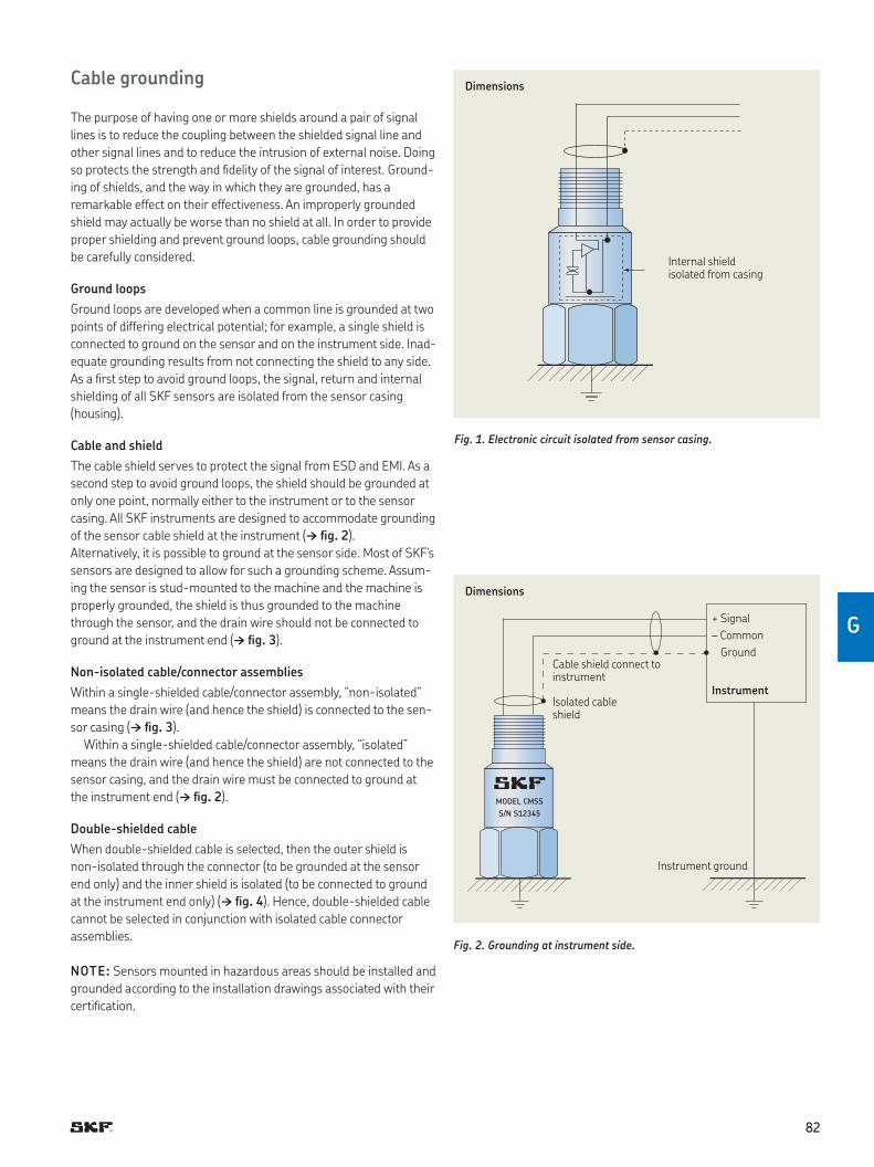
8282
G
Cable grounding
The purpose of having one or more shields around a pair of signal
lines is to reduce the coupling between the shielded signal line and
other signal lines and to reduce the intrusion of external noise Doing
so protects the strength and idelity of the signal of interest Ground-
ing of shields, and the way in which they are grounded, has a
remarkable effect on their effectiveness An improperly grounded
shield may actually be worse than no shield at all In order to provide
proper shielding and prevent ground loops, cable grounding should
be carefully considered
Ground loops
Ground loops are developed when a common line is grounded at two
points of differing electrical potential; for example, a single shield is
connected to ground on the sensor and on the instrument side Inad-
equate grounding results from not connecting the shield to any side
As a irst step to avoid ground loops, the signal, return and internal
shielding of all SKF sensors are isolated from the sensor casing
(housing)
Cable and shield
The cable shield serves to protect the signal from ESD and EMI As a
second step to avoid ground loops, the shield should be grounded at
only one point, normally either to the instrument or to the sensor
casing All SKF instruments are designed to accommodate grounding
of the sensor cable shield at the instrument († ig. 2)
Alternatively, it is possible to ground at the sensor side Most of SKF’s
sensors are designed to allow for such a grounding scheme Assum-
ing the sensor is stud-mounted to the machine and the machine is
properly grounded, the shield is thus grounded to the machine
through the sensor, and the drain wire should not be connected to
ground at the instrument end († ig. 3)
Non-isolated cable/connector assemblies
Within a single-shielded cable/connector assembly, “non-isolated”
means the drain wire (and hence the shield) is connected to the sen-
sor casing († ig. 3)
Within a single-shielded cable/connector assembly, “isolated”
means the drain wire (and hence the shield) are not connected to the
sensor casing, and the drain wire must be connected to ground at
the instrument end († ig. 2)
Double-shielded cable
When double-shielded cable is selected, then the outer shield is
non-isolated through the connector (to be grounded at the sensor
end only) and the inner shield is isolated (to be connected to ground
at the instrument end only) († ig. 4) Hence, double-shielded cable
cannot be selected in conjunction with isolated cable connector
assemblies
NOTE: Sensors mounted in hazardous areas should be installed and
grounded according to the installation drawings associated with their
certiication
MODEL CMSS
S/N S12345
Internal shield isolated from casing
+ Signal
– Common
Ground
InstrumentIsolated cable shield
Cable shield connect to instrument
Instrument ground
Fig. 1. Electronic circuit isolated from sensor casing.
Fig. 2. Grounding at instrument side.
Dimensions
Dimensions
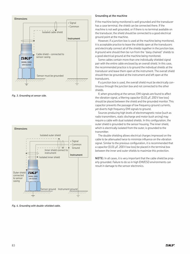
83
Grounding at the machine
If the machine being monitored is well grounded and the transducer
has a case terminal, the shield can be connected there If the
machine is not well grounded, or if there is no terminal available on
the transducer, the shield should be connected to a good electrical
ground point at the machine
However, if a junction box is used at the machine being monitored,
it is acceptable practice to leave the shields open at the transducers
and electrically connect all of the shields together in the junction box
A ground wire should then be run from the “daisy chained” shields to
a good electrical ground at the machine being monitored
Some cables contain more than one individually shielded signal
pair with the entire cable enclosed by an overall shield In this case,
the recommended practice is to ground the individual shields at the
transducer and leave them open at the instrument The overall shield
should then be grounded at the instrument and left open at the
transducers
If a junction box is used, the overall shield must be electrically con-
tinuous through the junction box and not connected to the other
shields
If, when grounding at the sensor, EMI signals are found to affect
the vibration signal, a iltering capacitor (0,01 µF, 200 V low loss)
should be placed between the shield and the grounded monitor This
capacitor prevents the passage of low frequency ground currents,
yet diverts high frequency EMI signals to ground
Sources producing high levels of electromagnetic noise (such as
radio transmitters, static discharge and motor bush arcing) may
require a cable with dual isolated shields In this coniguration, the
outer shield is grounded to the sensor housing The inner shield,
which is electrically isolated from the outer, is grounded to the
transmitter
The double shielding allows electrical charges impressed on the
cable to be attenuated twice to minimize inluence on the vibration
signal Similar to the previous coniguration, it is recommended that
a capacitor (0,01 µF, 200 V low loss) be placed in the terminal box
between the inner and outer shields to maximize this protection
NOTE: In all cases, it is very important that the cable shield be prop-
erly grounded Failure to do so in high EMI/ESD environments can
result in damage to the sensor electronics
MODEL CMSS
S/N S12345
MODEL CMSS
S/N S12345
+ Signal
– Common
Ground
Instrument
Isolated outer shield
Isolated inner shield
Outer shield connected to sensor casing
Sensor ground Instrument ground
Inner shield connect to instrument
+ Signal
– Common
Instrument
Cable shield – connected to sensor casing
Isolated cable shield
Sensor must be grounded
Fig. 3. Grounding at sensor side.
Fig. 4. Grounding with double-shielded cable.
Dimensions
Dimensions
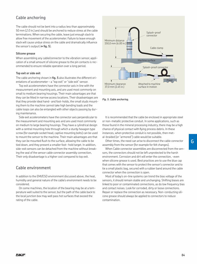
8484
G
Cable anchoring
The cable should not be bent into a radius less than approximately
50 mm (2.0 in.) and should be anchored to reduce stress at the cable
terminations When securing the cable, leave just enough slack to
allow free movement of the accelerometer Failure to leave enough
slack will cause undue stress on the cable and dramatically inluence
the sensor’s output († ig. 5)
Silicone grease
When assembling any cable/connector to the vibration sensor, appli-
cation of a small amount of silicone grease to the pin contacts is rec-
ommended to ensure reliable operation over a long period
Top exit or side exit
The cable anchoring shown in ig. 5 also illustrates the different ori-
entations of accelerometer – a “top exit” or “side exit” sensor
Top exit accelerometers have the connector axis in line with the
measurement and mounting axis, and are used most commonly on
small to medium bearing housings Their main advantages are that
they can be itted in narrow access locations Their disadvantages are
that they provide ideal hand- and foot-holds, the small studs mount-
ing them to the machine cannot take high bending loads and the
cable loops can also be entangled with other objects passing by dur-
ing maintenance
Side exit accelerometers have the connector axis perpendicular to
the measurement and mounting axis and are used most commonly
on medium to large bearing housings They have a cylindrical design
with a central mounting hole through which a sturdy hexagon type
screw (for example socket head, captive mounting bolts) can be used
to mount the sensor to the machine Their main advantages are that
they can be mounted lush to the surface, allowing the cable to be
tied down, and they present a smaller foot- hold target In addition,
side-exit sensors can be detached from the machine without break-
ing the seal of the sensor cable connector assembly connection,
Their only disadvantage is a higher cost compared to top exit
Cable environment
In addition to the EMI/ESD environment discussed above, the heat,
humidity and general nature of the cable’s environment needs to be
considered
On some machines, the location of the bearing may be at a tem-
perature well suited to the sensor, but the path of the cable back to
the local junction box may well pass hot surfaces that exceed the
rating of the cable
Splash-proof connector
Minimum distance 150,0 mm (6.00 in.)
Minimum clearance 37,0 mm (1.45 in.)
Cable clamp
Machine surface
Fixed
Splash-proof connector
Attached to machine surface in motion
Fig. 5. Cable anchoring.
It is recommended that the cable be enclosed in appropriate steel
or non-metallic protective conduit In some applications, such as
those found in the mineral processing industry, there may be a high
chance of physical contact with lying process debris In these
instances, when protective conduit is not possible, then met-
al-braided (or “armored”) cable would be suitable
Other times, the need can arise to disconnect the cable connector
assembly from the sensor (for example for felt changes)
When Cable connector assemblies are disconnected from the sen-
sors, the connectors should not be left unprotected to the harsh
environment Corrosion and dirt will enter the connection, -even
when silicone grease is used Best practices are to use the blue cap
that comes with the sensor to protect the sensor’s connector and to
tie a small plastic bag, secured with a rubber band around the cable
connector when the connection is open
Most of today’s on-line systems can trend the bias voltage of the
sensors, it should remain stable and unchanging Shifting biases are
linked to poor or contaminated connections, as do low frequency bias
and contact noises Look for corroded, dirty or loose connections
Repair or replace the connection as necessary Non-conducting sili-
cone grease should always be applied to connectors to reduce
contamination
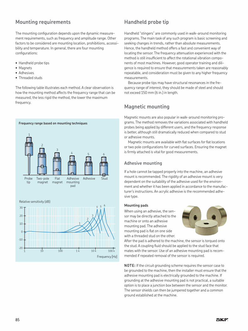
8585
Mounting requirements
The mounting coniguration depends upon the dynamic measure-
ment requirements, such as frequency and amplitude range Other
factors to be considered are mounting location, prohibitions, accessi-
bility and temperature In general, there are four mounting
conigurations:
• Handheld probe tips
• Magnets
• Adhesives
• Threaded studs
The following table illustrates each method A clear observation is
how the mounting method affects the frequency range that can be
measured; the less rigid the method, the lower the maximum
frequency
1
2
3
4 5 6
1 10 100 1 k 10 k 100 k
–10
0
10
20
30
–20
Relative sensitivity (dB)
65
3
2
1
4
Probe tip
Two-pole magnet
Flat magnet
Adhesive mounting
pad
Adhesive Stud
Handheld probe tip
Handheld “stingers” are commonly used in walk-around monitoring
programs The main task of any such program is basic screening and
seeking changes in trends, rather than absolute measurements
Hence, the handheld method offers a fast and convenient way of
locating the sensor The frequency attenuation experienced with the
method is still insuficient to affect the rotational vibration compo-
nents of most machines However, good operator training and dili-
gence is required to ensure that measurements taken are reasonably
repeatable, and consideration must be given to any higher frequency
measurements
Because probe tips may have structural resonances in the fre-
quency range of interest, they should be made of steel and should
not exceed 150 mm (6 in ) in length
Magnetic mounting
Magnetic mounts are also popular in walk-around monitoring pro-
grams The method removes the variations associated with handheld
probes being applied by different users, and the frequency response
is better, although still dramatically reduced when compared to stud
or adhesive mounts
Magnetic mounts are available with lat surfaces for lat locations
or two pole conigurations for curved surfaces Ensuring the magnet
is irmly attached is vital for good measurements
Adhesive mounting
If a hole cannot be tapped properly into the machine, an adhesive
mount is recommended The rigidity of an adhesive mount is very
dependent on the suitability of the adhesive used for the environ-
ment and whether it has been applied in accordance to the manufac-
turer’s instructions An acrylic adhesive is the recommended adhe-
sive type
Mounting pads
When using an adhesive, the sen-
sor may be directly attached to the
machine or onto an adhesive
mounting pad The adhesive
mounting pad is lat on one side
with a threaded stud on the other
After the pad is adhered to the machine, the sensor is torqued onto
the stud A coupling luid should be applied to the stud face that
mates with the sensor Use of an adhesive mounting pad is recom-
mended if repeated removal of the sensor is required
NOTE: If the circuit grounding scheme requires the sensor case to
be grounded to the machine, then the installer must ensure that the
adhesive mounting pad is electrically grounded to the machine If
grounding at the adhesive mounting pad is not practical, a suitable
option is to place a junction box between the sensor and the monitor
The sensor shields can then be jumpered together and a common
ground established at the machine
Frequency range based on mounting techniques
Frequency [Hz]
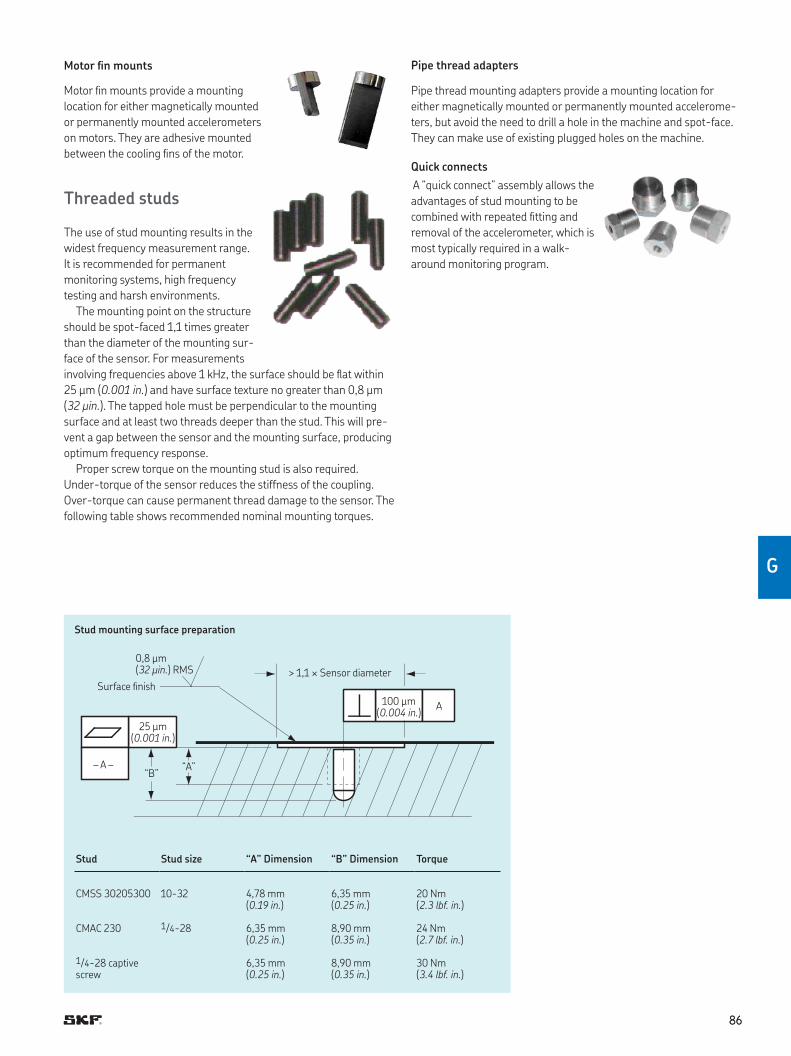
8686
G
Motor in mounts
Motor in mounts provide a mounting
location for either magnetically mounted
or permanently mounted accelerometers
on motors They are adhesive mounted
between the cooling ins of the motor
Threaded studs
The use of stud mounting results in the
widest frequency measurement range
It is recommended for permanent
monitoring systems, high frequency
testing and harsh environments
The mounting point on the structure
should be spot-faced 1,1 times greater
than the diameter of the mounting sur-
face of the sensor For measurements
involving frequencies above 1 kHz, the surface should be lat within
25 µm (0.001 in.) and have surface texture no greater than 0,8 µm
(32 µin.) The tapped hole must be perpendicular to the mounting
surface and at least two threads deeper than the stud This will pre-
vent a gap between the sensor and the mounting surface, producing
optimum frequency response
Proper screw torque on the mounting stud is also required
Under-torque of the sensor reduces the stiffness of the coupling
Over-torque can cause permanent thread damage to the sensor The
following table shows recommended nominal mounting torques
Pipe thread adapters
Pipe thread mounting adapters provide a mounting location for
either magnetically mounted or permanently mounted accelerome-
ters, but avoid the need to drill a hole in the machine and spot-face
They can make use of existing plugged holes on the machine
Quick connects
A “quick connect” assembly allows the
advantages of stud mounting to be
combined with repeated itting and
removal of the accelerometer, which is
most typically required in a walk-
around monitoring program
Surface inish
0,8 µm (32 µin.) RMS > 1,1 × Sensor diameter
100 µm (0.004 in.)
A
25 µm (0.001 in.)
– A –“B”
“A”
Stud mounting surface preparation
Stud Stud size “A” Dimension “B” Dimension Torque
CMSS 30205300 10-32 4,78 mm (0.19 in.)
6,35 mm (0.25 in.)
20 Nm (2.3 lbf. in.)
CMAC 230 1/4-28 6,35 mm (0.25 in.)
8,90 mm (0.35 in.)
24 Nm (2.7 lbf. in.)
1/4-28 captive screw
6,35 mm (0.25 in.)
8,90 mm (0.35 in.)
30 Nm (3.4 lbf. in.)
8787
Maintenance considerations
In general, piezoelectric accelerometers are almost mainte-
nance-free, with only a small number of factors that need to be
remembered, as follows
Sensitivity validation
Regular sensitivity validation (or “calibration”) is not usually a
requirement For example, the procedure is unnecessary in condition
monitoring applications where changes in gross vibrations are being
measured and extreme accuracy is not a concern
If high accuracy amplitude measurements are required, sensor
calibration should be veriied once a year and can normally be done
on-site by a qualiied technician with a vibration generator/shaker
device A piezoelectric accelerometer cannot be adjusted, so any vari-
ation measured must be accommodated by adjusting the sensitivity
used by the monitor system
Bias output voltage monitoring
A good indicator of accelerometer health can be found in its ”bias
output voltage” The bias output voltage is the base DC voltage upon
which the AC vibration signal is carried and is typically around 12 V
DC
A regular check of the bias output voltage, or a continuous trend in
an on-line system, can reveal deterioration in the electronics within
the sensor, which may be caused by the environment (such as tem-
perature) It can also lag damage to cabling Complete absence of
the bias output voltage will indicate a break in the cable or circuit
Self generating velocity sensors
These sensors wear out over time, as they contain moving parts An
annual sensitivity check is recommended
Summary
Vibration sensors are the initial source of machinery information
upon which productivity, product quality and personnel safety deci-
sions are based
It is crucial that sensors be properly selected and installed to
ensure reliable signal information Procedures should be imple-
mented to monitor the performance of all measurement channels to
further ensure the integrity of the vibration information base Fol-
lowing this process will increase the effectiveness of your vibration
monitoring program and improve productivity of plant personnel and
equipment
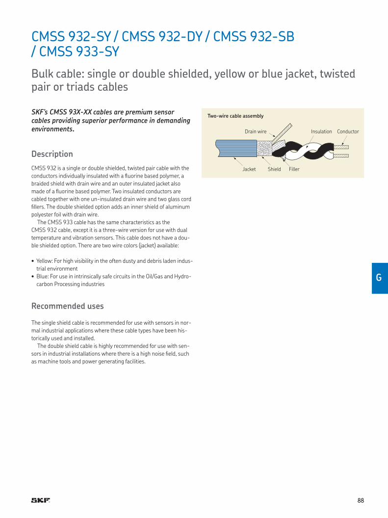
8888
G
SKF’s CMSS 93X-XX cables are premium sensor cables providing superior performance in demanding environments.
Description
CMSS 932 is a single or double shielded, twisted pair cable with the
conductors individually insulated with a luorine based polymer, a
braided shield with drain wire and an outer insulated jacket also
made of a luorine based polymer Two insulated conductors are
cabled together with one un-insulated drain wire and two glass cord
illers The double shielded option adds an inner shield of aluminum
polyester foil with drain wire
The CMSS 933 cable has the same characteristics as the
CMSS 932 cable, except it is a three-wire version for use with dual
temperature and vibration sensors This cable does not have a dou-
ble shielded option There are two wire colors (jacket) available:
• Yellow: For high visibility in the often dusty and debris laden indus-
trial environment
• Blue: For use in intrinsically safe circuits in the Oil/Gas and Hydro-
carbon Processing industries
Recommended uses
The single shield cable is recommended for use with sensors in nor-
mal industrial applications where these cable types have been his-
torically used and installed
The double shield cable is highly recommended for use with sen-
sors in industrial installations where there is a high noise ield, such
as machine tools and power generating facilities
CMSS 932-SY / CMSS 932-DY / CMSS 932-SB / CMSS 933-SY
Bulk cable: single or double shielded, yellow or blue jacket, twisted pair or triads cables
Two-wire cable assembly
Drain wire
Jacket Shield Filler
Insulation Conductor
8989
– Color code:
Conductor: Black and white pair
Jacket: Yellow (Y) or blue (B)
– Color code for CMSS 932:
A = White = Acceleration signal/power
B = Black = Common
– Color code for CMSS 933:
A = Red = Acceleration signal/power
B = Black = Acceleration and temperature common
C = White = Temperature signal
– Dimensions:
Conductor: 0,96 mm (0 038 in ) nominal
Insulation: 1,40 mm (0 058 in ) nominal
Drain wire: 0,61 mm (0 024 in ) nominal
Shield: 3,50 mm (0 138 in ) nominal
Jacket: 4,80 mm, ±0,1 mm (0 190 in , ±0 005 in )
Ordering information
CMSS 932-SY-150M Two-conductor, twisted pair, single shield, yellow cable with continuous cable length, 150 m (500 ft.) spool CMSS 932-SY-300M Two-conductor, twisted pair, single shield, yellow cable with continuous cable length, 300 m (1 000 ft.) spool CMSS 932-DY-150M Two-conductor, twisted pair, double shield, yellow cable with continuous cable length, 150 m (500 ft.) spool CMSS 932-SB-150M Two-conductor, twisted pair, single shield, blue cable with continuous cable length, 150 m (500 ft.) spool CMSS 933-SY-150M Three-conductor, triad, single shield, yellow cable with continuous cable length, 150 m (500 ft.) spool
Speciications (all models)
Electrical
• Capacitance: Approximately 89 pF/m (27 pF/ft.)
• Voltage rating: 600 V RMS maximum continuous use
Environmental
• Minimum bend radius: 48 mm (1.9 in.)
• Working temperature range: –80 to +200 °C (–110 to +390 °F)
• Heat and lame resistance: Non-lame propagating
• Plenum rated
• Meets ROHS requirements
Physical
• Materials:
– Conductor: Tin plated copper, 19 × 32 strands, size 20 AWG
(American Wire Gauge)
– Insulation: Extruded FEP
– Drain wire: Tin plated copper, 7 × 32 strands, size 24 AWG
– Shield: 36 AWG tin plated copper braid
– Jacket: Extruded FEP
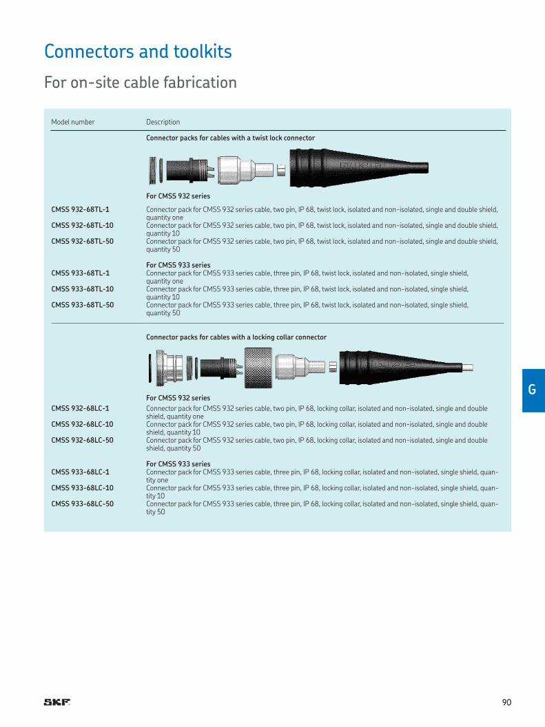
9090
G
Connectors and toolkits
For on-site cable fabrication
Model number Description
Connector packs for cables with a twist lock connector
For CMSS 932 series
CMSS 932-68TL-1 Connector pack for CMSS 932 series cable, two pin, IP 68, twist lock, isolated and non-isolated, single and double shield, quantity one
CMSS 932-68TL-10 Connector pack for CMSS 932 series cable, two pin, IP 68, twist lock, isolated and non-isolated, single and double shield, quantity 10
CMSS 932-68TL-50 Connector pack for CMSS 932 series cable, two pin, IP 68, twist lock, isolated and non-isolated, single and double shield, quantity 50
For CMSS 933 seriesCMSS 933-68TL-1 Connector pack for CMSS 933 series cable, three pin, IP 68, twist lock, isolated and non-isolated, single shield,
quantity oneCMSS 933-68TL-10 Connector pack for CMSS 933 series cable, three pin, IP 68, twist lock, isolated and non-isolated, single shield,
quantity 10CMSS 933-68TL-50 Connector pack for CMSS 933 series cable, three pin, IP 68, twist lock, isolated and non-isolated, single shield,
quantity 50
Connector packs for cables with a locking collar connector
For CMSS 932 series
CMSS 932-68LC-1 Connector pack for CMSS 932 series cable, two pin, IP 68, locking collar, isolated and non-isolated, single and double shield, quantity one
CMSS 932-68LC-10 Connector pack for CMSS 932 series cable, two pin, IP 68, locking collar, isolated and non-isolated, single and double shield, quantity 10
CMSS 932-68LC-50 Connector pack for CMSS 932 series cable, two pin, IP 68, locking collar, isolated and non-isolated, single and double shield, quantity 50
For CMSS 933 seriesCMSS 933-68LC-1 Connector pack for CMSS 933 series cable, three pin, IP 68, locking collar, isolated and non-isolated, single shield, quan-
tity oneCMSS 933-68LC-10 Connector pack for CMSS 933 series cable, three pin, IP 68, locking collar, isolated and non-isolated, single shield, quan-
tity 10CMSS 933-68LC-50 Connector pack for CMSS 933 series cable, three pin, IP 68, locking collar, isolated and non-isolated, single shield, quan-
tity 50

9191
Connectors and toolkits
For on-site cable fabrication (continued)
Model number Description
CMSS 930-68-K Toolkit for ield installationToolkit for ield installation for CMSS 93x series cable, IP 68 connectors, single and double shield (excludes connectors), for 25 to 50 connectors
Each toolkit contains:
• Crimp tool• Crimp tool positioner• Crimp tool frame• Exacto knife• Exacto knife blades (15)• Scissors• Wire stripper• High temperature epoxy (3 pack) (must use within two months)• Epoxy mix applicator gun• Metal socket insertion tool• Plastic socket insertion tool (2)• Epoxy mixing plunger• Epoxy nozzle (static mixing tubes) (10)
Epoxy nozzle (static mixing tubes), 10 each
High temperature epoxy, 3 each
Epoxy applicator gun with 4:1 plunger
15 blades
Crimp tool
Exacto knife
Wire stripper
Metal socket inser-tion tool
Plastic socket inser-tion tool, 2 each
Scissors
Crimp frame tool and crimp positioner tool
CMSS 930-68-K Toolkit for ield installation
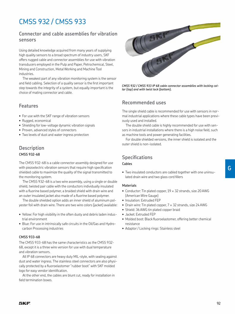
9292
G
CMSS 932 / CMSS 933
Connector and cable assemblies for vibration sensors
Using detailed knowledge acquired from many years of supplying
high quality sensors to a broad spectrum of industry users, SKF
offers rugged cable and connector assemblies for use with vibration
transducers employed in the Pulp and Paper, Petrochemical, Steel,
Mining and Construction, Metal Working and Machine Tool
industries
The weakest part of any vibration monitoring system is the sensor
and ield cabling Selection of a quality sensor is the irst important
step towards the integrity of a system, but equally important is the
choice of mating connector and cable
Features
• For use with the SKF range of vibration sensors
• Rugged, economical
• Shielding for low-voltage dynamic vibration signals
• Proven, advanced styles of connectors
• Two levels of dust and water ingress protection
DescriptionCMSS 932-68
The CMSS 932-68 is a cable connector assembly designed for use
with piezoelectric vibration sensors that require high speciication
shielded cable to maximize the quality of the signal transmitted to
the monitoring system
The CMSS 932-68 is a two wire assembly, using a single or double
shield, twisted pair cable with the conductors individually insulated
with a luorine based polymer, a braided shield with drain wire and
an outer insulated jacket also made of a luorine based polymer
The double shielded option adds an inner shield of aluminum pol-
yester foil with drain wire There are two wire colors (jacket) available:
• Yellow: For high visibility in the often dusty and debris laden indus-
trial environment
• Blue: For use in intrinsically safe circuits in the Oil/Gas and Hydro-
carbon Processing industries
CMSS 933-68
The CMSS 933-68 has the same characteristics as the CMSS 932-
68, except it is a three wire version for use with dual temperature
and vibration sensors
All IP 68 connectors are heavy duty MIL-style, with sealing against
dust and water ingress The stainless steel connectors are also physi-
cally protected by a luoroelastomer “rubber boot” with SKF molded
logo for easy vendor identiication
At the other end, the cables are blunt cut, ready for installation in
ield termination boxes
Recommended uses
The single shield cable is recommended for use with sensors in nor-
mal industrial applications where these cable types have been previ-
ously used and installed
The double shield cable is highly recommended for use with sen-
sors in industrial installations where there is a high noise ield, such
as machine tools and power generating facilities
For double shielded versions, the inner shield is isolated and the
outer shield is non-isolated
SpeciicationsCables
• Two insulated conductors are cabled together with one uninsu-
lated drain wire and two glass cord illers
Materials
• Conductor: Tin plated copper, 19 × 32 strands, size 20 AWG
(American Wire Gauge)
• Insulation: Extruded FEP
• Drain wire: Tin plated copper, 7 × 32 strands, size 24 AWG
• Shield: 36 AWG tin plated copper braid
• Jacket: Extruded FEP
• Molded boot: Black luoroelastomer, offering better chemical
resistance
• Adaptor / Locking rings: Stainless steel
CMSS 932 / CMSS 933 IP 68 cable connector assemblies with locking col-lar (top) and with twist lock (bottom).
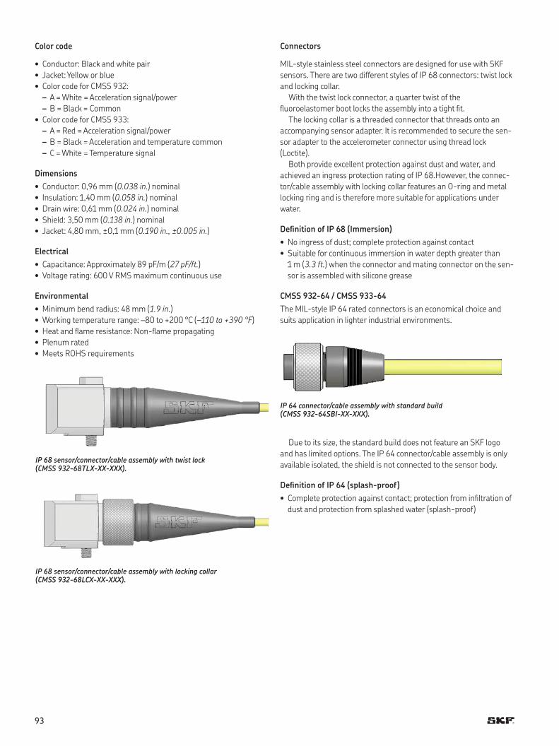
9393
Connectors
MIL-style stainless steel connectors are designed for use with SKF
sensors There are two different styles of IP 68 connectors: twist lock
and locking collar
With the twist lock connector, a quarter twist of the
luoroelastomer boot locks the assembly into a tight it
The locking collar is a threaded connector that threads onto an
accompanying sensor adapter It is recommended to secure the sen-
sor adapter to the accelerometer connector using thread lock
(Loctite)
Both provide excellent protection against dust and water, and
achieved an ingress protection rating of IP 68 However, the connec-
tor/cable assembly with locking collar features an O-ring and metal
locking ring and is therefore more suitable for applications under
water
Deinition of IP 68 (Immersion)
• No ingress of dust; complete protection against contact
• Suitable for continuous immersion in water depth greater than
1 m (3.3 ft.) when the connector and mating connector on the sen-
sor is assembled with silicone grease
CMSS 932-64 / CMSS 933-64
The MIL-style IP 64 rated connectors is an economical choice and
suits application in lighter industrial environments
IP 64 connector/cable assembly with standard build (CMSS 932-64SBI-XX-XXX).
Due to its size, the standard build does not feature an SKF logo
and has limited options The IP 64 connector/cable assembly is only
available isolated, the shield is not connected to the sensor body
Deinition of IP 64 (splash-proof)
• Complete protection against contact; protection from iniltration of
dust and protection from splashed water (splash-proof)
IP 68 sensor/connector/cable assembly with twist lock (CMSS 932-68TLX-XX-XXX).
IP 68 sensor/connector/cable assembly with locking collar (CMSS 932-68LCX-XX-XXX).
Color code
• Conductor: Black and white pair
• Jacket: Yellow or blue
• Color code for CMSS 932:
– A = White = Acceleration signal/power
– B = Black = Common
• Color code for CMSS 933:
– A = Red = Acceleration signal/power
– B = Black = Acceleration and temperature common
– C = White = Temperature signal
Dimensions
• Conductor: 0,96 mm (0.038 in.) nominal
• Insulation: 1,40 mm (0.058 in.) nominal
• Drain wire: 0,61 mm (0.024 in.) nominal
• Shield: 3,50 mm (0.138 in.) nominal
• Jacket: 4,80 mm, ±0,1 mm (0.190 in., ±0.005 in.)
Electrical
• Capacitance: Approximately 89 pF/m (27 pF/ft.)
• Voltage rating: 600 V RMS maximum continuous use
Environmental
• Minimum bend radius: 48 mm (1.9 in.)
• Working temperature range: –80 to +200 °C (–110 to +390 °F)
• Heat and lame resistance: Non-lame propagating
• Plenum rated
• Meets ROHS requirements
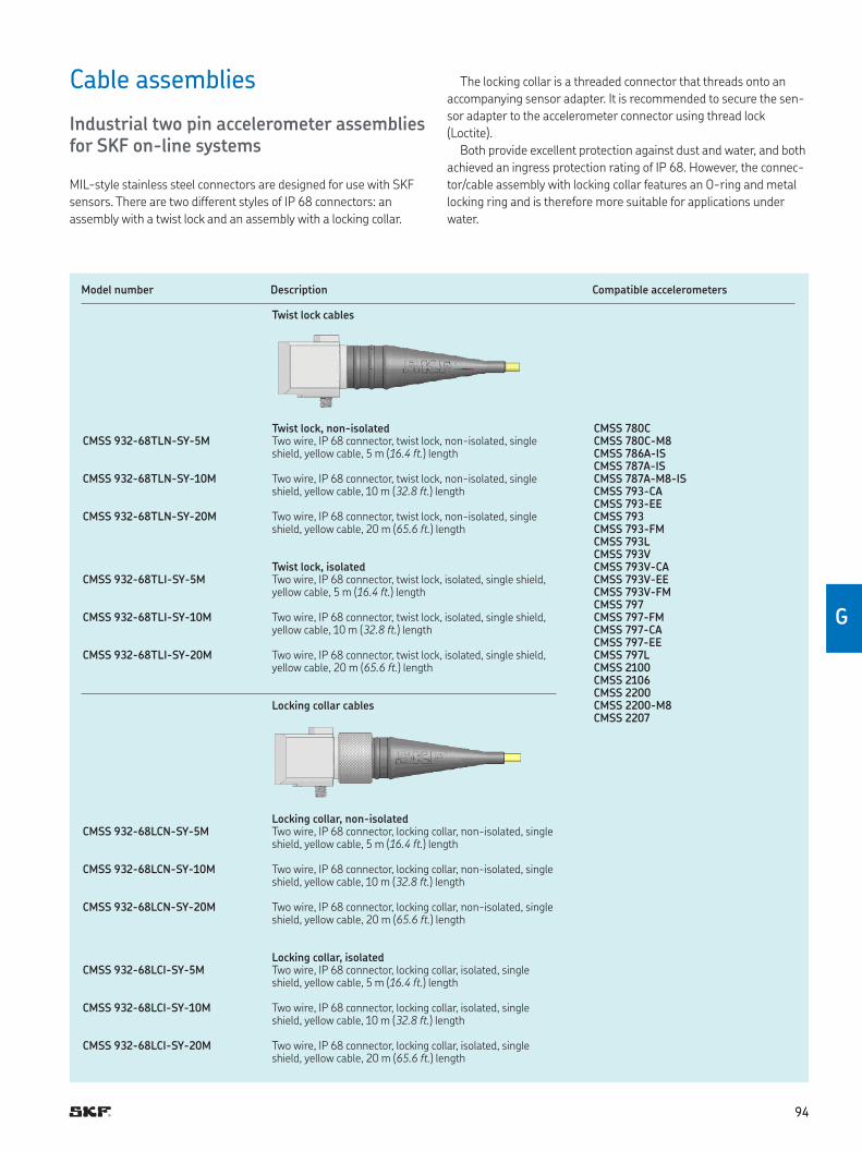
9494
G
Cable assemblies
Industrial two pin accelerometer assemblies for SKF on-line systems
MIL-style stainless steel connectors are designed for use with SKF
sensors There are two different styles of IP 68 connectors: an
assembly with a twist lock and an assembly with a locking collar
Model number Description Compatible accelerometers
Twist lock cables
Twist lock, non-isolated CMSS 780CCMSS 780C-M8CMSS 786A-ISCMSS 787A-ISCMSS 787A-M8-ISCMSS 793-CACMSS 793-EECMSS 793CMSS 793-FMCMSS 793LCMSS 793VCMSS 793V-CACMSS 793V-EECMSS 793V-FMCMSS 797CMSS 797-FMCMSS 797-CACMSS 797-EECMSS 797LCMSS 2100CMSS 2106CMSS 2200CMSS 2200-M8CMSS 2207
CMSS 932-68TLN-SY-5M Two wire, IP 68 connector, twist lock, non-isolated, single shield, yellow cable, 5 m (16.4 ft.) length
CMSS 932-68TLN-SY-10M Two wire, IP 68 connector, twist lock, non-isolated, single shield, yellow cable, 10 m (32.8 ft.) length
CMSS 932-68TLN-SY-20M Two wire, IP 68 connector, twist lock, non-isolated, single shield, yellow cable, 20 m (65.6 ft.) length
Twist lock, isolatedCMSS 932-68TLI-SY-5M Two wire, IP 68 connector, twist lock, isolated, single shield,
yellow cable, 5 m (16.4 ft.) length
CMSS 932-68TLI-SY-10M Two wire, IP 68 connector, twist lock, isolated, single shield,yellow cable, 10 m (32.8 ft.) length
CMSS 932-68TLI-SY-20M Two wire, IP 68 connector, twist lock, isolated, single shield,yellow cable, 20 m (65.6 ft.) length
Locking collar cables
CMSS 932-68LCN-SY-5MLocking collar, non-isolatedTwo wire, IP 68 connector, locking collar, non-isolated, single shield, yellow cable, 5 m (16.4 ft.) length
CMSS 932-68LCN-SY-10M Two wire, IP 68 connector, locking collar, non-isolated, single shield, yellow cable, 10 m (32.8 ft.) length
CMSS 932-68LCN-SY-20M Two wire, IP 68 connector, locking collar, non-isolated, single shield, yellow cable, 20 m (65.6 ft.) length
Locking collar, isolatedCMSS 932-68LCI-SY-5M Two wire, IP 68 connector, locking collar, isolated, single
shield, yellow cable, 5 m (16.4 ft.) length
CMSS 932-68LCI-SY-10M Two wire, IP 68 connector, locking collar, isolated, single shield, yellow cable, 10 m (32.8 ft.) length
CMSS 932-68LCI-SY-20M Two wire, IP 68 connector, locking collar, isolated, single shield, yellow cable, 20 m (65.6 ft.) length
The locking collar is a threaded connector that threads onto an
accompanying sensor adapter It is recommended to secure the sen-
sor adapter to the accelerometer connector using thread lock
(Loctite)
Both provide excellent protection against dust and water, and both
achieved an ingress protection rating of IP 68 However, the connec-
tor/cable assembly with locking collar features an O-ring and metal
locking ring and is therefore more suitable for applications under
water
9595
Cable assemblies
Economical two-pin accelerometer assemblies
The MIL-style IP 64 rated connector is an economical choice and
suits applications in lighter industrial environments Due to its size,
the standard build does not feature an SKF logo and has limited
options The IP 64 connector/cable assembly is only available iso-
lated; the shield is not connected to the sensor body
Model number Description Compatible accelerometers
Standard build cables CMSS 780CCMSS 780C-M8CMSS 786A-ISCMSS 787A-ISCMSS 787A-M8-ISCMSS 793CMSS 793-FMCMSS 793-CACMSS 793-EECMSS 793LCMSS 793VCMSS 793V-CACMSS 793V-EECMSS 793V-FMCMSS 797CMSS 797-FMCMSS 797-CACMSS 797-EECMSS 797LCMSS 2100CMSS 2106CMSS 2200CMSS 2200-M8CMSS 2207
Standard build, isolatedCMSS 932-64SBI-SY-5M Two wire, IP 64 connector, standard build, isolated, single
shield, yellow cable, 5 m (16 4 ft ) length
CMSS 932-64SBI-SY-10M Two wire, IP 64 connector, standard build, isolated, single shield, yellow cable, 10 m (32 8 ft ) length
CMSS 932 -64SBI-SY-20M Two wire, IP 64 connector, standard build, isolated, single shield, yellow cable, 20 m (65 6 ft ) length
CMSS 932-64SBI-SY-30M Two wire, IP 64 connector, standard build, isolated, single shield, yellow cable, 30 m (98 4 ft ) length
CMSS 932-64SBI-SY-50M Two wire, IP 64 connector, standard build, isolated, single shield, yellow cable, 50 m (164 ft ) length
9696
G
Cable assemblies
Industrial three pin cable assemblies
Model number Description Compatible accelerometers
Twist lock cables
Twist lock, non-isolated CMSS 786T-ISCMSS 793T-3CMSS 797T-1CMSS 2100TCMSS 2200TCMSS 2350T-D2
CMSS 933-68TLN-SY-10M Three wire, IP 68 connector, twist lock, non-isolated, single shield, yellow cable, 10 m (32.8 ft.) length
CMSS 933-68TLN-SY-20M Three wire, IP 68 connector, twist lock, non-isolated, single shield, yellow cable, 20 m (65.6 ft.) length
Twist lock, isolatedCMSS 933-68TLI-SY-10M Three wire, IP 68 connector, twist lock, isolated, single
shield, yellow cable, 10 m (32.8 ft.) length
CMSS 933-68TLI-SY-20M Three wire, IP 68 connector, twist lock, isolated, single shield, yellow cable, 20 m (65.6 ft.) length
Locking collar cables
Locking collar, non-isolatedCMSS 933-68LCN-SY-5M Three wire, IP 68 connector, locking collar, non-isolated,
single shield, yellow cable, 5 m (16.4 ft.) length
CMSS 933-68LCN-SY-10M Three wire, IP 68 connector, locking collar, non-isolated, single shield, yellow cable, 10 m (32.8 ft.) length
CMSS 933-68LCN-SY-20M Three wire, IP 68 connector, locking collar, non-isolated, single shield, yellow cable, 20 m (65.6 ft.) length
Locking collar, isolatedCMSS 933-68LCI-SY-5M Three wire, IP 68 connector, locking collar, isolated, single
shield, yellow cable, 5 m (16.4 ft.) length
CMSS 933-68LCI-SY-10M Three wire, IP 68 connector, locking collar, isolated, single shield, yellow cable, 10 m (32.8 ft.) length
CMSS 933-68LCI-SY-20M Three wire, IP 68 connector, locking collar, isolated, single shield, yellow cable, 20 m (65.6 ft.) length
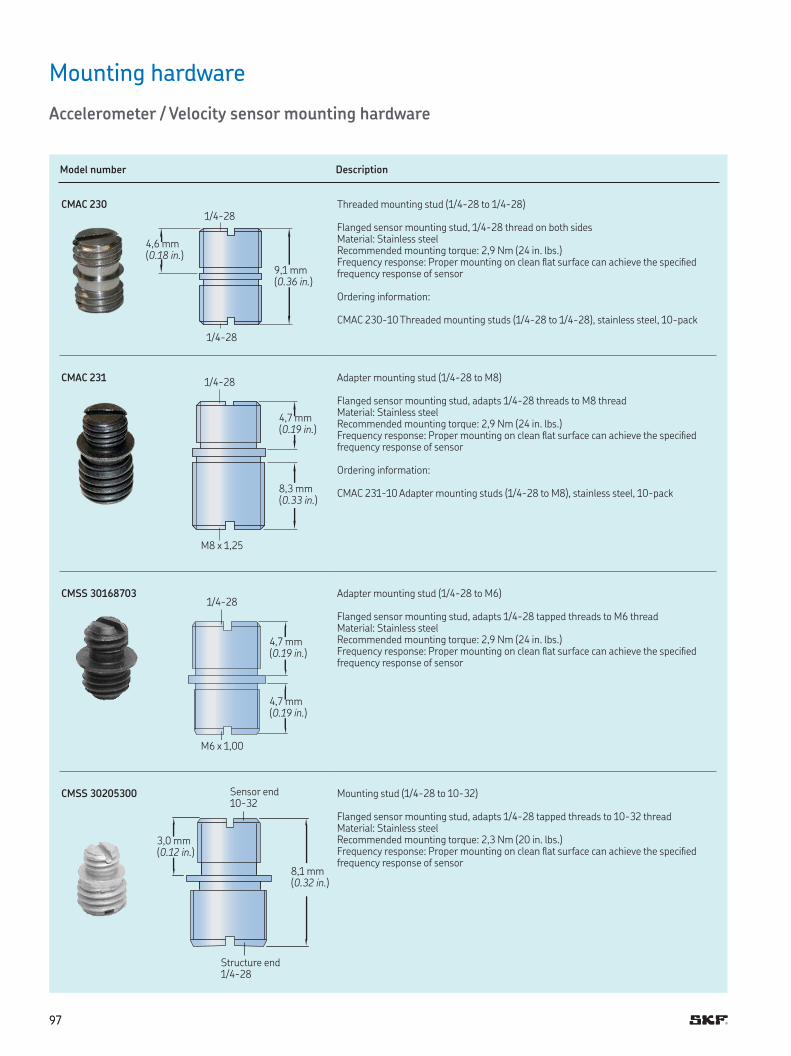
9797
Mounting hardware
Accelerometer / Velocity sensor mounting hardware
Model number Description
CMAC 230 Threaded mounting stud (1/4-28 to 1/4-28)
Flanged sensor mounting stud, 1/4-28 thread on both sidesMaterial: Stainless steelRecommended mounting torque: 2,9 Nm (24 in lbs )Frequency response: Proper mounting on clean lat surface can achieve the speciied frequency response of sensor
Ordering information:
CMAC 230-10 Threaded mounting studs (1/4-28 to 1/4-28), stainless steel, 10-pack
CMAC 231 Adapter mounting stud (1/4-28 to M8)
Flanged sensor mounting stud, adapts 1/4-28 threads to M8 threadMaterial: Stainless steelRecommended mounting torque: 2,9 Nm (24 in lbs )Frequency response: Proper mounting on clean lat surface can achieve the speciied frequency response of sensor
Ordering information:
CMAC 231-10 Adapter mounting studs (1/4-28 to M8), stainless steel, 10-pack
CMSS 30168703 Adapter mounting stud (1/4-28 to M6)
Flanged sensor mounting stud, adapts 1/4-28 tapped threads to M6 threadMaterial: Stainless steelRecommended mounting torque: 2,9 Nm (24 in lbs )Frequency response: Proper mounting on clean lat surface can achieve the speciied frequency response of sensor
CMSS 30205300 Mounting stud (1/4-28 to 10-32)
Flanged sensor mounting stud, adapts 1/4-28 tapped threads to 10-32 threadMaterial: Stainless steelRecommended mounting torque: 2,3 Nm (20 in lbs )Frequency response: Proper mounting on clean lat surface can achieve the speciied frequency response of sensor
1/4-28
4,6 mm (0.18 in.)
1/4-28
9,1 mm (0.36 in.)
1/4-28
1/4-28
Sensor end 10-32
Structure end 1/4-28
4,7 mm (0.19 in.)
4,7 mm (0.19 in.)
3,0 mm (0.12 in.)
8,1 mm (0.32 in.)
4,7 mm (0.19 in.)
8,3 mm (0.33 in.)
M8 x 1,25
M6 x 1,00
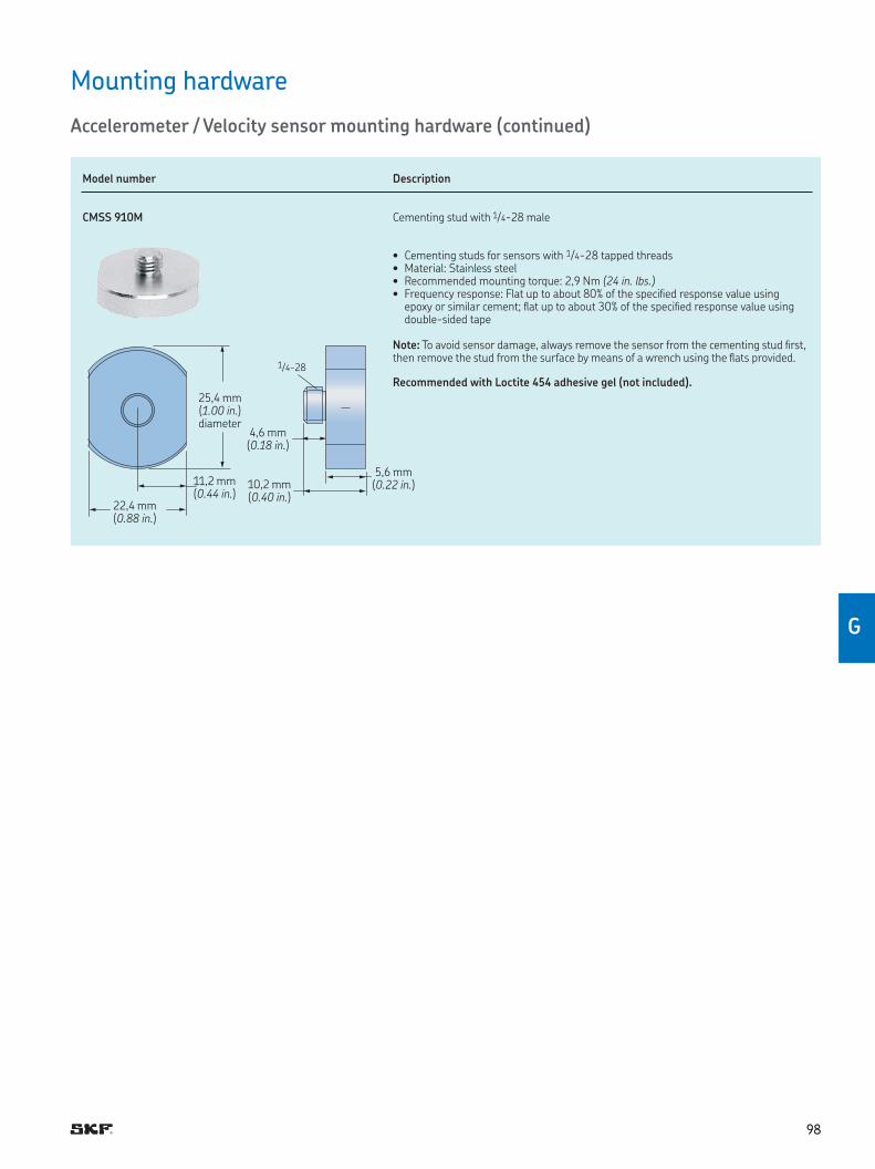
9898
G
Mounting hardware
Accelerometer / Velocity sensor mounting hardware (continued)
Model number Description
CMSS 910M Cementing stud with 1/4-28 male
• Cementing studs for sensors with 1/4-28 tapped threads• Material: Stainless steel• Recommended mounting torque: 2,9 Nm (24 in. lbs.)• Frequency response: Flat up to about 80% of the speciied response value using
epoxy or similar cement; lat up to about 30% of the speciied response value using double-sided tape
Note: To avoid sensor damage, always remove the sensor from the cementing stud irst, then remove the stud from the surface by means of a wrench using the lats provided
Recommended with Loctite 454 adhesive gel (not included).
22,4 mm (0.88 in.)
11,2 mm (0.44 in.)
25,4 mm (1.00 in ) diameter
10,2 mm (0.40 in.)
5,6 mm (0.22 in.)
4,6 mm (0.18 in.)
1/4-28
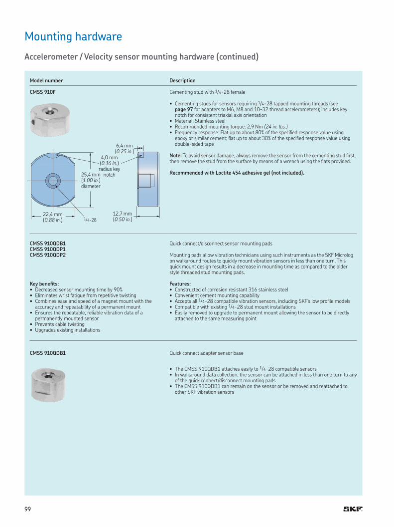
9999
Mounting hardware
Accelerometer / Velocity sensor mounting hardware (continued)
Model number Description
CMSS 910F Cementing stud with 1/4-28 female
• Cementing studs for sensors requiring 1/4-28 tapped mounting threads (see page 97 for adapters to M6, M8 and 10-32 thread accelerometers); includes key notch for consistent triaxial axis orientation
• Material: Stainless steel• Recommended mounting torque: 2,9 Nm (24 in. lbs.)• Frequency response: Flat up to about 80% of the speciied response value using
epoxy or similar cement; lat up to about 30% of the speciied response value using double-sided tape
Note: To avoid sensor damage, always remove the sensor from the cementing stud irst, then remove the stud from the surface by means of a wrench using the lats provided
Recommended with Loctite 454 adhesive gel (not included).
CMSS 910QDB1CMSS 910QDP1CMSS 910QDP2
Quick connect/disconnect sensor mounting pads
Mounting pads allow vibration technicians using such instruments as the SKF Microlog on walkaround routes to quickly mount vibration sensors in less than one turn This quick mount design results in a decrease in mounting time as compared to the older style threaded stud mounting pads
Key benefits:• Decreased sensor mounting time by 90%• Eliminates wrist fatigue from repetitive twisting• Combines ease and speed of a magnet mount with the
accuracy and repeatability of a permanent mount• Ensures the repeatable, reliable vibration data of a
permanently mounted sensor• Prevents cable twisting• Upgrades existing installations
Features:• Constructed of corrosion resistant 316 stainless steel• Convenient cement mounting capability• Accepts all 1/4-28 compatible vibration sensors, including SKF’s low proile models• Compatible with existing 1/4-28 stud mount installations• Easily removed to upgrade to permanent mount allowing the sensor to be directly
attached to the same measuring point
CMSS 910QDB1 Quick connect adapter sensor base
• The CMSS 910QDB1 attaches easily to 1/4-28 compatible sensors• In walkaround data collection, the sensor can be attached in less than one turn to any
of the quick connect/disconnect mounting pads• The CMSS 910QDB1 can remain on the sensor or be removed and reattached to
other SKF vibration sensors
22,4 mm (0.88 in.)
12,7 mm (0.50 in.)
25,4 mm (1.00 in.) diameter
4,0 mm (0.16 in.)
radius key notch
6,4 mm (0.25 in )
1/4-28
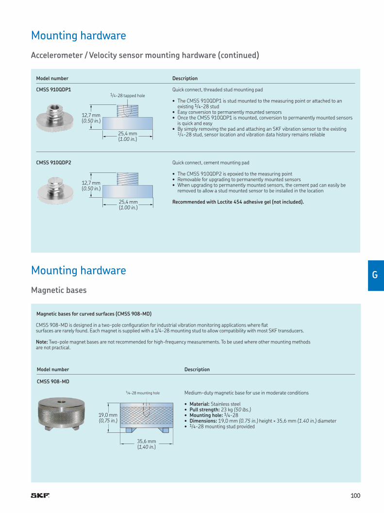
100100
G
Mounting hardware
Accelerometer / Velocity sensor mounting hardware (continued)
Model number Description
CMSS 910QDP1 Quick connect, threaded stud mounting pad
• The CMSS 910QDP1 is stud mounted to the measuring point or attached to an existing 1/4-28 stud
• Easy conversion to permanently mounted sensors• Once the CMSS 910QDP1 is mounted, conversion to permanently mounted sensors
is quick and easy• By simply removing the pad and attaching an SKF vibration sensor to the existing
1/4-28 stud, sensor location and vibration data history remains reliable
CMSS 910QDP2 Quick connect, cement mounting pad
• The CMSS 910QDP2 is epoxied to the measuring point• Removable for upgrading to permanently mounted sensors• When upgrading to permanently mounted sensors, the cement pad can easily be
removed to allow a stud mounted sensor to be installed in the location
Recommended with Loctite 454 adhesive gel (not included).
12,7 mm (0.50 in.)
25,4 mm (1.00 in.)
1/4-28 tapped hole
25,4 mm (1.00 in.)
12,7 mm (0.50 in.)
Magnetic bases for curved surfaces (CMSS 908-MD)
CMSS 908-MD is designed in a two-pole coniguration for industrial vibration monitoring applications where lat surfaces are rarely found Each magnet is supplied with a 1/4-28 mounting stud to allow compatibility with most SKF transducers Note: Two-pole magnet bases are not recommended for high-frequency measurements To be used where other mounting methods are not practical
Model number Description
CMSS 908-MD
Medium-duty magnetic base for use in moderate conditions
• Material: Stainless steel• Pull strength: 23 kg (50 lbs.)• Mounting hole: 1/4-28• Dimensions: 19,0 mm (0.75 in.) height × 35,6 mm (1.40 in.) diameter• 1/4-28 mounting stud provided
1/4-28 mounting hole
19,0 mm(0,75 in.)
35,6 mm(1,40 in.)
Mounting hardware
Magnetic bases
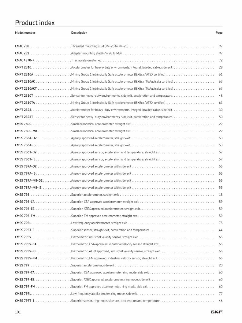
101
CMAC 230 . . . . . . . . . . . . . . . . . . . . . . . . .Threaded mounting stud (1/4-28 to 1/4-28) . . . . . . . . . . . . . . . . . . . . . . . . . . . . . . . . . . . . . . . . . . . . . . . . . . . 97
CMAC 231 . . . . . . . . . . . . . . . . . . . . . . . . .Adapter mounting stud (1/4-28 to M8) . . . . . . . . . . . . . . . . . . . . . . . . . . . . . . . . . . . . . . . . . . . . . . . . . . . . . . . 97
CMAC 4370-K . . . . . . . . . . . . . . . . . . . . . .Triax accelerometer kit . . . . . . . . . . . . . . . . . . . . . . . . . . . . . . . . . . . . . . . . . . . . . . . . . . . . . . . . . . . . . . . . . . . 72
CMPT 2310. . . . . . . . . . . . . . . . . . . . . . . .Accelerometer for heavy-duty environments, integral, braided cable, side exit . . . . . . . . . . . . . . . . . . . . . . . . . 28
CMPT 2310A . . . . . . . . . . . . . . . . . . . . . .Mining Group 1 Intrinsically Safe accelerometer (IEXEcx / ATEX certiied) . . . . . . . . . . . . . . . . . . . . . . . . . . . . . 61
CMPT 2310AC . . . . . . . . . . . . . . . . . . . . .Mining Group 1 Intrinsically Safe accelerometer (IEXEcx ITA Australia certiied) . . . . . . . . . . . . . . . . . . . . . . . . 63
CMPT 2310ACT . . . . . . . . . . . . . . . . . . . .Mining Group 1 Intrinsically Safe accelerometer (IEXEcx ITA Australia certiied) . . . . . . . . . . . . . . . . . . . . . . . . 63
CMPT 2310T . . . . . . . . . . . . . . . . . . . . . .Sensor for heavy-duty environments, side exit, acceleration and temperature . . . . . . . . . . . . . . . . . . . . . . . . . 48
CMPT 2310TA . . . . . . . . . . . . . . . . . . . . .Mining Group 1 Intrinsically Safe accelerometer (IEXEcx / ATEX certiied) . . . . . . . . . . . . . . . . . . . . . . . . . . . . . 61
CMPT 2323. . . . . . . . . . . . . . . . . . . . . . . .Accelerometer for heavy-duty environments, integral, braided cable, side exit . . . . . . . . . . . . . . . . . . . . . . . . . 30
CMPT 2323T . . . . . . . . . . . . . . . . . . . . . .Sensor for heavy-duty environments, side exit, acceleration and temperature . . . . . . . . . . . . . . . . . . . . . . . . . 50
CMSS 780C. . . . . . . . . . . . . . . . . . . . . . . .Small economical accelerometer, straight exit . . . . . . . . . . . . . . . . . . . . . . . . . . . . . . . . . . . . . . . . . . . . . . . . . 22
CMSS 780C-M8 . . . . . . . . . . . . . . . . . . . .Small economical accelerometer, straight exit . . . . . . . . . . . . . . . . . . . . . . . . . . . . . . . . . . . . . . . . . . . . . . . . . 22
CMSS 786A-D2 . . . . . . . . . . . . . . . . . . . .Agency approved accelerometer, straight exit . . . . . . . . . . . . . . . . . . . . . . . . . . . . . . . . . . . . . . . . . . . . . . . . . . 53
CMSS 786A-IS . . . . . . . . . . . . . . . . . . . . .Agency approved accelerometer, straight exit . . . . . . . . . . . . . . . . . . . . . . . . . . . . . . . . . . . . . . . . . . . . . . . . . . 53
CMSS 786T-D2 . . . . . . . . . . . . . . . . . . . .Agency approved sensor, acceleration and temperature, straight exit . . . . . . . . . . . . . . . . . . . . . . . . . . . . . . . . 57
CMSS 786T-IS . . . . . . . . . . . . . . . . . . . . .Agency approved sensor, acceleration and temperature, straight exit . . . . . . . . . . . . . . . . . . . . . . . . . . . . . . . . 57
CMSS 787A-D2 . . . . . . . . . . . . . . . . . . . .Agency approved accelerometer with side exit . . . . . . . . . . . . . . . . . . . . . . . . . . . . . . . . . . . . . . . . . . . . . . . . . 55
CMSS 787A-IS . . . . . . . . . . . . . . . . . . . . .Agency approved accelerometer with side exit . . . . . . . . . . . . . . . . . . . . . . . . . . . . . . . . . . . . . . . . . . . . . . . . . 55
CMSS 787A-M8-D2 . . . . . . . . . . . . . . . . .Agency approved accelerometer with side exit . . . . . . . . . . . . . . . . . . . . . . . . . . . . . . . . . . . . . . . . . . . . . . . . . 55
CMSS 787A-M8-IS. . . . . . . . . . . . . . . . . .Agency approved accelerometer with side exit . . . . . . . . . . . . . . . . . . . . . . . . . . . . . . . . . . . . . . . . . . . . . . . . . 55
CMSS 793. . . . . . . . . . . . . . . . . . . . . . . . .Superior accelerometer, straight exit . . . . . . . . . . . . . . . . . . . . . . . . . . . . . . . . . . . . . . . . . . . . . . . . . . . . . . . . 18
CMSS 793-CA. . . . . . . . . . . . . . . . . . . . . .Superior, CSA approved accelerometer, straight exit . . . . . . . . . . . . . . . . . . . . . . . . . . . . . . . . . . . . . . . . . . . . . 59
CMSS 793-EE. . . . . . . . . . . . . . . . . . . . . .Superior, ATEX approved accelerometer, straight exit . . . . . . . . . . . . . . . . . . . . . . . . . . . . . . . . . . . . . . . . . . . . 59
CMSS 793-FM . . . . . . . . . . . . . . . . . . . . .Superior, FM approved accelerometer, straight exit . . . . . . . . . . . . . . . . . . . . . . . . . . . . . . . . . . . . . . . . . . . . . 59
CMSS 793L. . . . . . . . . . . . . . . . . . . . . . . .Low frequency accelerometer, straight exit . . . . . . . . . . . . . . . . . . . . . . . . . . . . . . . . . . . . . . . . . . . . . . . . . . . . 75
CMSS 793T-3. . . . . . . . . . . . . . . . . . . . . .Superior sensor, straight exit, acceleration and temperature . . . . . . . . . . . . . . . . . . . . . . . . . . . . . . . . . . . . . . 44
CMSS 793V. . . . . . . . . . . . . . . . . . . . . . . .Piezoelectric industrial velocity sensor, straight exit . . . . . . . . . . . . . . . . . . . . . . . . . . . . . . . . . . . . . . . . . . . . . 65
CMSS 793V-CA . . . . . . . . . . . . . . . . . . . .Piezoelectric, CSA approved, industrial velocity sensor, straight exit . . . . . . . . . . . . . . . . . . . . . . . . . . . . . . . . . 65
CMSS 793V-EE . . . . . . . . . . . . . . . . . . . .Piezoelectric, ATEX approved, industrial velocity sensor, straight exit . . . . . . . . . . . . . . . . . . . . . . . . . . . . . . . . 65
CMSS 793V-FM . . . . . . . . . . . . . . . . . . . .Piezoelectric, FM approved, industrial velocity sensor, straight exit . . . . . . . . . . . . . . . . . . . . . . . . . . . . . . . . . . 65
CMSS 797. . . . . . . . . . . . . . . . . . . . . . . . .Superior accelerometer, side exit . . . . . . . . . . . . . . . . . . . . . . . . . . . . . . . . . . . . . . . . . . . . . . . . . . . . . . . . . . . 20
CMSS 797-CA. . . . . . . . . . . . . . . . . . . . . .Superior, CSA approved accelerometer, ring mode, side exit . . . . . . . . . . . . . . . . . . . . . . . . . . . . . . . . . . . . . . . 60
CMSS 797-EE. . . . . . . . . . . . . . . . . . . . . .Superior, ATEX approved accelerometer, ring mode, side exit . . . . . . . . . . . . . . . . . . . . . . . . . . . . . . . . . . . . . . 60
CMSS 797-FM . . . . . . . . . . . . . . . . . . . . .Superior, FM approved accelerometer, ring mode, side exit . . . . . . . . . . . . . . . . . . . . . . . . . . . . . . . . . . . . . . . 60
CMSS 797L. . . . . . . . . . . . . . . . . . . . . . . .Low frequency accelerometer, ring mode, side exit. . . . . . . . . . . . . . . . . . . . . . . . . . . . . . . . . . . . . . . . . . . . . . 77
CMSS 797T-1. . . . . . . . . . . . . . . . . . . . . .Superior sensor, ring mode, side exit, acceleration and temperature . . . . . . . . . . . . . . . . . . . . . . . . . . . . . . . . 46
Product index
Model number Description Page
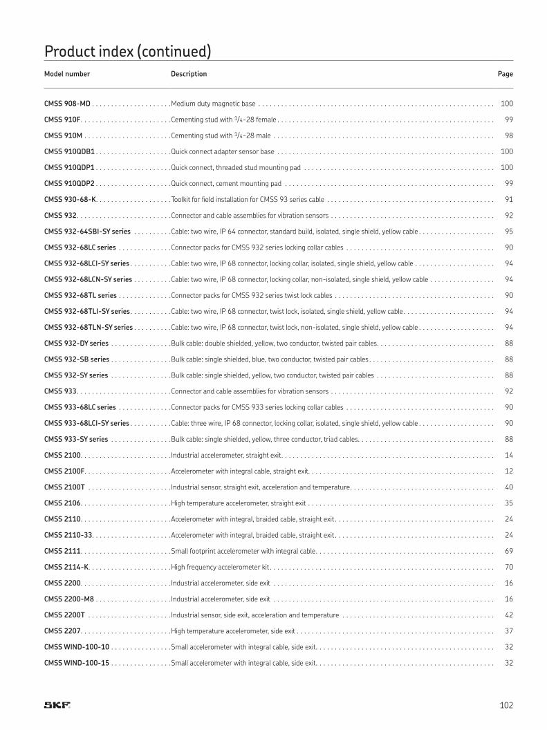
102
CMSS 908-MD . . . . . . . . . . . . . . . . . . . . .Medium duty magnetic base . . . . . . . . . . . . . . . . . . . . . . . . . . . . . . . . . . . . . . . . . . . . . . . . . . . . . . . . . . . . . . 100
CMSS 910F. . . . . . . . . . . . . . . . . . . . . . . .Cementing stud with 1/4-28 female . . . . . . . . . . . . . . . . . . . . . . . . . . . . . . . . . . . . . . . . . . . . . . . . . . . . . . . . . 99
CMSS 910M . . . . . . . . . . . . . . . . . . . . . . .Cementing stud with 1/4-28 male . . . . . . . . . . . . . . . . . . . . . . . . . . . . . . . . . . . . . . . . . . . . . . . . . . . . . . . . . . 98
CMSS 910QDB1 . . . . . . . . . . . . . . . . . . . .Quick connect adapter sensor base . . . . . . . . . . . . . . . . . . . . . . . . . . . . . . . . . . . . . . . . . . . . . . . . . . . . . . . . . 100
CMSS 910QDP1 . . . . . . . . . . . . . . . . . . . .Quick connect, threaded stud mounting pad . . . . . . . . . . . . . . . . . . . . . . . . . . . . . . . . . . . . . . . . . . . . . . . . . . 100
CMSS 910QDP2 . . . . . . . . . . . . . . . . . . . .Quick connect, cement mounting pad . . . . . . . . . . . . . . . . . . . . . . . . . . . . . . . . . . . . . . . . . . . . . . . . . . . . . . . 99
CMSS 930-68-K. . . . . . . . . . . . . . . . . . . .Toolkit for ield installation for CMSS 93 series cable . . . . . . . . . . . . . . . . . . . . . . . . . . . . . . . . . . . . . . . . . . . . 91
CMSS 932. . . . . . . . . . . . . . . . . . . . . . . . .Connector and cable assemblies for vibration sensors . . . . . . . . . . . . . . . . . . . . . . . . . . . . . . . . . . . . . . . . . . . 92
CMSS 932-64SBI-SY series . . . . . . . . . .Cable: two wire, IP 64 connector, standard build, isolated, single shield, yellow cable . . . . . . . . . . . . . . . . . . . . 95
CMSS 932-68LC series . . . . . . . . . . . . . .Connector packs for CMSS 932 series locking collar cables . . . . . . . . . . . . . . . . . . . . . . . . . . . . . . . . . . . . . . . 90
CMSS 932-68LCI-SY series . . . . . . . . . . .Cable: two wire, IP 68 connector, locking collar, isolated, single shield, yellow cable . . . . . . . . . . . . . . . . . . . . . 94
CMSS 932-68LCN-SY series . . . . . . . . . .Cable: two wire, IP 68 connector, locking collar, non-isolated, single shield, yellow cable . . . . . . . . . . . . . . . . . 94
CMSS 932-68TL series . . . . . . . . . . . . . .Connector packs for CMSS 932 series twist lock cables . . . . . . . . . . . . . . . . . . . . . . . . . . . . . . . . . . . . . . . . . . 90
CMSS 932-68TLI-SY series. . . . . . . . . . .Cable: two wire, IP 68 connector, twist lock, isolated, single shield, yellow cable . . . . . . . . . . . . . . . . . . . . . . . . 94
CMSS 932-68TLN-SY series . . . . . . . . . .Cable: two wire, IP 68 connector, twist lock, non-isolated, single shield, yellow cable . . . . . . . . . . . . . . . . . . . . 94
CMSS 932-DY series . . . . . . . . . . . . . . . .Bulk cable: double shielded, yellow, two conductor, twisted pair cables . . . . . . . . . . . . . . . . . . . . . . . . . . . . . . . 88
CMSS 932-SB series . . . . . . . . . . . . . . . .Bulk cable: single shielded, blue, two conductor, twisted pair cables . . . . . . . . . . . . . . . . . . . . . . . . . . . . . . . . . 88
CMSS 932-SY series . . . . . . . . . . . . . . . .Bulk cable: single shielded, yellow, two conductor, twisted pair cables . . . . . . . . . . . . . . . . . . . . . . . . . . . . . . . 88
CMSS 933. . . . . . . . . . . . . . . . . . . . . . . . .Connector and cable assemblies for vibration sensors . . . . . . . . . . . . . . . . . . . . . . . . . . . . . . . . . . . . . . . . . . . 92
CMSS 933-68LC series . . . . . . . . . . . . . .Connector packs for CMSS 933 series locking collar cables . . . . . . . . . . . . . . . . . . . . . . . . . . . . . . . . . . . . . . . 90
CMSS 933-68LCI-SY series . . . . . . . . . . .Cable: three wire, IP 68 connector, locking collar, isolated, single shield, yellow cable . . . . . . . . . . . . . . . . . . . . 90
CMSS 933-SY series . . . . . . . . . . . . . . . .Bulk cable: single shielded, yellow, three conductor, triad cables. . . . . . . . . . . . . . . . . . . . . . . . . . . . . . . . . . . . 88
CMSS 2100. . . . . . . . . . . . . . . . . . . . . . . . Industrial accelerometer, straight exit . . . . . . . . . . . . . . . . . . . . . . . . . . . . . . . . . . . . . . . . . . . . . . . . . . . . . . . . 14
CMSS 2100F. . . . . . . . . . . . . . . . . . . . . . .Accelerometer with integral cable, straight exit. . . . . . . . . . . . . . . . . . . . . . . . . . . . . . . . . . . . . . . . . . . . . . . . . 12
CMSS 2100T . . . . . . . . . . . . . . . . . . . . . . Industrial sensor, straight exit, acceleration and temperature . . . . . . . . . . . . . . . . . . . . . . . . . . . . . . . . . . . . . . 40
CMSS 2106. . . . . . . . . . . . . . . . . . . . . . . .High temperature accelerometer, straight exit . . . . . . . . . . . . . . . . . . . . . . . . . . . . . . . . . . . . . . . . . . . . . . . . . 35
CMSS 2110. . . . . . . . . . . . . . . . . . . . . . . .Accelerometer with integral, braided cable, straight exit . . . . . . . . . . . . . . . . . . . . . . . . . . . . . . . . . . . . . . . . . . 24
CMSS 2110-33. . . . . . . . . . . . . . . . . . . . .Accelerometer with integral, braided cable, straight exit . . . . . . . . . . . . . . . . . . . . . . . . . . . . . . . . . . . . . . . . . . 24
CMSS 2111. . . . . . . . . . . . . . . . . . . . . . . .Small footprint accelerometer with integral cable . . . . . . . . . . . . . . . . . . . . . . . . . . . . . . . . . . . . . . . . . . . . . . . 69
CMSS 2114-K. . . . . . . . . . . . . . . . . . . . . .High frequency accelerometer kit . . . . . . . . . . . . . . . . . . . . . . . . . . . . . . . . . . . . . . . . . . . . . . . . . . . . . . . . . . . 70
CMSS 2200. . . . . . . . . . . . . . . . . . . . . . . . Industrial accelerometer, side exit . . . . . . . . . . . . . . . . . . . . . . . . . . . . . . . . . . . . . . . . . . . . . . . . . . . . . . . . . . 16
CMSS 2200-M8 . . . . . . . . . . . . . . . . . . . . Industrial accelerometer, side exit . . . . . . . . . . . . . . . . . . . . . . . . . . . . . . . . . . . . . . . . . . . . . . . . . . . . . . . . . . 16
CMSS 2200T . . . . . . . . . . . . . . . . . . . . . . Industrial sensor, side exit, acceleration and temperature . . . . . . . . . . . . . . . . . . . . . . . . . . . . . . . . . . . . . . . . 42
CMSS 2207. . . . . . . . . . . . . . . . . . . . . . . .High temperature accelerometer, side exit . . . . . . . . . . . . . . . . . . . . . . . . . . . . . . . . . . . . . . . . . . . . . . . . . . . . 37
CMSS WIND-100-10 . . . . . . . . . . . . . . . .Small accelerometer with integral cable, side exit . . . . . . . . . . . . . . . . . . . . . . . . . . . . . . . . . . . . . . . . . . . . . . . 32
CMSS WIND-100-15 . . . . . . . . . . . . . . . .Small accelerometer with integral cable, side exit . . . . . . . . . . . . . . . . . . . . . . . . . . . . . . . . . . . . . . . . . . . . . . . 32
Product index (continued)
Model number Description Page
Please contact:
SKF SwedenAurorum 30, SE-977 75 Lulea, SwedenTel: +46 31 337 1000, Support: +46 31 337 6500
Web: www.skf.com/cm® SKF, MICROLOG, and MULTILOG are registered trademarks of the SKF Group
CSA is a registered trademark of Canadian Standards Association
Loctite is a registered trademark of Henkel Corporation
All other trademarks are the property of their respective owners
© SKF Group 2018The contents of this publication are the copyright of the publisher and may not be reproduced (even extracts) unless prior written permission is granted Every care has been taken to ensure the accuracy of the information contained in this publication but no liability can be accepted for any loss or damage whether direct, indirect or consequential arising out of the use of the information contained herein
Patents: US 4,768,380 · US 5,633,811 · US 5,679,900 · US 5,845,230 · US 5,852,351 · US 5,854,553 · US 5,854,994 · US 5,870,699 · US 5,907,491 · US 5,992,237 US 6,006,164 · US 6,124,692 · US 6,138,078 · US 6,199,422 · US 6,202,491 · US 6,275,781 · US 6,301,514 · US 6,437,692 · US 6,489,884 · US 6,513,386 · US 6,633,822 · US 6,789,025 · US 6,792,360 · US 7,103,511 · US 7,697,492 · WO/2003/048714
PUB CM/P1 11604/16 EN · May 2018
Certain image(s) used under license from Shutterstock com