
SKF Shaft Alignment Tool Horizontal machines app · 2 EN 1. Using the Horizontal shaft alignment...
24
Short flex couplings SKF Shaft Alignment Tool Horizontal machines app Instructions for use
Transcript of SKF Shaft Alignment Tool Horizontal machines app · 2 EN 1. Using the Horizontal shaft alignment...
Short flex couplings
SKF Shaft Alignment ToolHorizontal machines app
Instructions for use

1EN
1. Using the Horizontal shaft alignment app .................................................................................. 21.1 How to change the app language ..............................................................................................................21.2 Main menu ....................................................................................................................................................31.3 Settings .........................................................................................................................................................41.4 Select units ....................................................................................................................................................51.5 Machine information ....................................................................................................................................51.6 Sensor status ................................................................................................................................................91.7 Measuring procedure ................................................................................................................................ 101.8 Manual measuring with ixed angles ...................................................................................................... 131.9 “As Found” measuring results ................................................................................................................. 141.10 Vertical correction ..................................................................................................................................... 151.11 Horizontal correction ................................................................................................................................ 161.12 Verify the alignment .................................................................................................................................. 161.13 “As Corrected” measuring results ........................................................................................................... 171.14 Report ...................................................................................................................................................... 181.15 Machine library .......................................................................................................................................... 19
Table of contents
Original instructions
2 EN
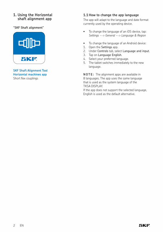
1. Using the Horizontal shaft alignment app
“SKF Shaft alignment”
SKF Shaft Alignment ToolHorizontal machines appShort l ex couplings
1.1 How to change the app language
The app will adapt to the language and date format currently used by the operating device.
• To change the language of an iOS device, tap: Settings --> General --> Language & Region
• To change the language of an Android device:1. Open the Settings app.2. Under Controls tab, select Language and input.3. Tap on Language English.4. Select your preferred language.5. The tablet switches immediately to the new
language.
N OT E : The alignment apps are available in 8 languages. The app uses the same language that is used as the system language of the TKSA DISPLAY. If the app does not support the selected language, English is used as the default alternative.
3EN
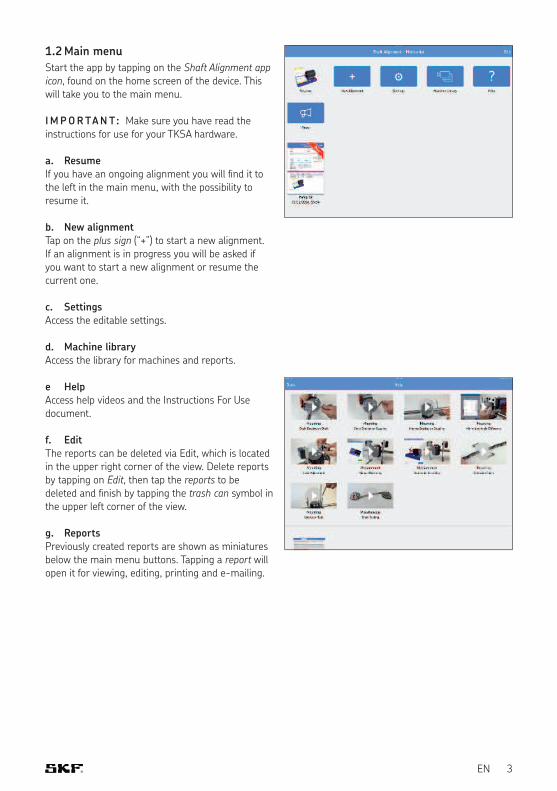
1.2 Main menu
Start the app by tapping on the Shaft Alignment app icon, found on the home screen of the device. This will take you to the main menu.
I M P O R TA N T: Make sure you have read the instructions for use for your TKSA hardware.
a. ResumeIf you have an ongoing alignment you will ind it to the left in the main menu, with the possibility to resume it.
b. New alignmentTap on the plus sign (“+”) to start a new alignment. If an alignment is in progress you will be asked if you want to start a new alignment or resume the current one.
c. SettingsAccess the editable settings.
d. Machine libraryAccess the library for machines and reports.
e HelpAccess help videos and the Instructions For Use document.
f. EditThe reports can be deleted via Edit, which is located in the upper right corner of the view. Delete reports by tapping on Edit, then tap the reports to be deleted and inish by tapping the trash can symbol in the upper left corner of the view.
g. ReportsPreviously created reports are shown as miniatures below the main menu buttons. Tapping a report will open it for viewing, editing, printing and e-mailing.
4 EN
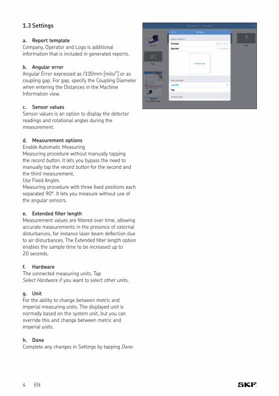
1.3 Settings
a. Report templateCompany, Operator and Logo is additional information that is included in generated reports.
b. Angular errorAngular Error expressed as /100mm [mils/”] or as coupling gap. For gap, specify the Coupling Diameter when entering the Distances in the Machine Information view.
c. Sensor valuesSensor values is an option to display the detector readings and rotational angles during the measurement.
d. Measurement optionsEnable Automatic MeasuringMeasuring procedure without manually tapping the record button. It lets you bypass the need to manually tap the record button for the second and the third measurement.Use Fixed AnglesMeasuring procedure with three ixed positions each separated 90°. It lets you measure without use of the angular sensors.
e. Extended filter lengthMeasurement values are iltered over time, allowing accurate measurements in the presence of external disturbances, for instance laser beam delection due to air disturbances. The Extended ilter length option enables the sample time to be increased up to 20 seconds.
f. HardwareThe connected measuring units. Tap Select Hardware if you want to select other units.
g. UnitFor the ability to change between metric and imperial measuring units. The displayed unit is normally based on the system unit, but you can override this and change between metric and imperial units.
h. DoneComplete any changes in Settings by tapping Done.
5EN
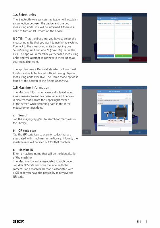
1.4 Select units
The Bluetooth wireless communication will establish a connection between the device and the two measuring units. You will be informed if there is a need to turn on Bluetooth on the device.
N OT E : That the irst time, you have to select the measuring units that you want to use in the system. Connect to the measuring units by tapping one S (stationary) unit and one M (movable) unit in the lists. The app will remember your chosen measuring units and will attempt to connect to these units at your next alignment.
The app features a Demo Mode which allows most functionalities to be tested without having physical measuring units available. The Demo Mode option is found at the bottom of the Select Units view.
1.5 Machine information
The Machine Information view is displayed when a new measurement has been initiated. The view is also reachable from the upper right corner of the screen while recording data in the three measurement positions.
a. SearchTap the magnifying glass to search for machines in the library.
b. QR code scanTap the QR code icon to scan for codes that are associated with machines in the library. If found, the machine info will be illed out for that machine.
c. Machine IDEnter a machine name that will be the identiication of the machine.The Machine ID can be associated to a QR code. Tap Add QR code and scan the label with the camera. For a machine ID that is associated with a QR code you have the possibility to remove the QR code.
6 EN
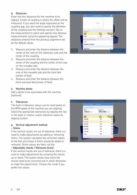
d. DistancesEnter the four distances for the machine to be aligned. Center of coupling is where the offset will be measured. If you want the angle expressed as the coupling gap, you also need to specify the diameter of the coupling (see the Settings section). Tap on the measurement to select and specify new distance measurements using the appearing keypad. The distances entered from the previous alignment will be the default values.
1. Measure and enter the distance between the center of the rods on the stationary side and the center of the coupling.
2. Measure and enter the distance between the center of the coupling and the center of the rods on the movable side.
3. Measure and enter the distance between the rods of the movable side and the front feet (center of feet).
4. Measure and enter the distance between the front and back feet (center of feet).
e. Machine photoAdd a photo to be associated with the machine (optional).
f. TolerancesThe built-in tolerance values can be used based on the RPM speed of the machine you are aligning. Select the appropriate tolerances by tapping the row in the table or choose custom tolerance values by tapping Custom.
g. Vertical adjustment method– ShimsIf the vertical results are out of tolerance, there is a need to make adjustments by adding or removing shims. The system calculates the correction values at the feet and shows if shims should be added or removed. Shims values are ixed, not live.– Adjustable chocks / Vibracons (Live)If the vertical results are out of tolerance, there is a need to make adjustments by screwing the chocks up or down. The system shows how much the chocks need to be corrected and in which directions to make the adjustments. Choose this mode if you prefer live values.
7EN
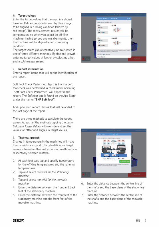
h. Target valuesEnter the target values that the machine should have in off-line condition (shown by blue image) to be aligned in running condition (shown by red image). The measurement results will be compensated so when you adjust an off-line machine, having zeroed any misalignments, then the machine will be aligned when in running condition.The target values can alternatively be calculated in one of three different methods. By thermal growth, entering target values at feet or by selecting a hot and a cold measurement.
i. Report informationEnter a report name that will be the identiication of the report.
Soft Foot Check Performed: Tap this box if a Soft foot check was performed. A check mark indicating “Soft Foot Check Performed” will appear in the report. The Soft foot app is found on the App Storeunder the name: “SKF Soft foot”.
Add up to four Report Photos that will be added to the last page of the report.
There are three methods to calculate the target values. At each of the methods tapping the button Calculate Target Values will override and set the values for offset and angles in Target Values.
j. Thermal growthChange in temperature in the machines will make them shrink or expand. The calculation for target values is based on thermal expansion coeficients for respectively selected material.
1. At each feet pair, tap and specify temperature for the off-line temperatures and the running temperatures.
2. Tap and select material for the stationary machine.
3. Tap and select material for the movable machine.
4. Enter the distance between the front and back feet of the stationary machine.
5. Enter the distance between the front feet of the stationary machine and the front feet of the movable machine.
6. Enter the distance between the centre line of the shafts and the base plane of the stationary machine.
7. Enter the distance between the centre line of the shafts and the base plane of the movable machine.
8 EN
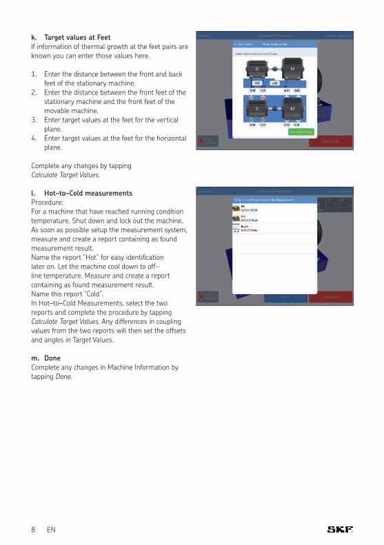
k. Target values at FeetIf information of thermal growth at the feet pairs are known you can enter those values here.
1. Enter the distance between the front and back feet of the stationary machine.
2. Enter the distance between the front feet of the stationary machine and the front feet of the movable machine.
3. Enter target values at the feet for the vertical plane.
4. Enter target values at the feet for the horizontal plane.
Complete any changes by tapping Calculate Target Values.
l. Hot–to–Cold measurementsProcedure:For a machine that have reached running condition temperature. Shut down and lock out the machine. As soon as possible setup the measurement system, measure and create a report containing as found measurement result. Name the report “Hot” for easy identiication later on. Let the machine cool down to off-line temperature. Measure and create a report containing as found measurement result. Name this report “Cold”.In Hot–to–Cold Measurements, select the two reports and complete the procedure by tapping Calculate Target Values. Any differences in coupling values from the two reports will then set the offsets and angles in Target Values.
m. DoneComplete any changes in Machine Information by tapping Done.
9EN
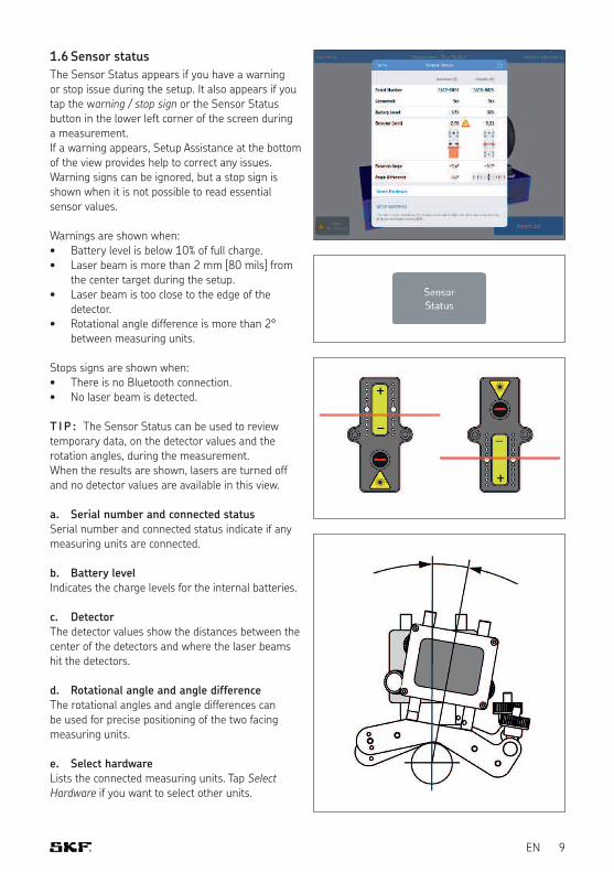
1.6 Sensor status
The Sensor Status appears if you have a warning or stop issue during the setup. It also appears if you tap the warning / stop sign or the Sensor Status button in the lower left corner of the screen during a measurement. If a warning appears, Setup Assistance at the bottom of the view provides help to correct any issues. Warning signs can be ignored, but a stop sign is shown when it is not possible to read essential sensor values.
Warnings are shown when:• Battery level is below 10% of full charge.• Laser beam is more than 2 mm [80 mils] from
the center target during the setup.• Laser beam is too close to the edge of the
detector.• Rotational angle difference is more than 2°
between measuring units.
Stops signs are shown when:• There is no Bluetooth connection.• No laser beam is detected.
T I P : The Sensor Status can be used to review temporary data, on the detector values and the rotation angles, during the measurement. When the results are shown, lasers are turned off and no detector values are available in this view.
a. Serial number and connected statusSerial number and connected status indicate if any measuring units are connected.
b. Battery levelIndicates the charge levels for the internal batteries.
c. DetectorThe detector values show the distances between the center of the detectors and where the laser beams hit the detectors.
d. Rotational angle and angle differenceThe rotational angles and angle differences can be used for precise positioning of the two facing measuring units.
e. Select hardwareLists the connected measuring units. Tap Select Hardware if you want to select other units.
10 EN
f. DoneWhen no warnings are displayed tap Done to proceed to the measurement.
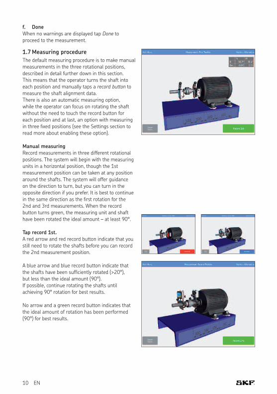
1.7 Measuring procedure
The default measuring procedure is to make manual measurements in the three rotational positions, described in detail further down in this section. This means that the operator turns the shaft into each position and manually taps a record button to measure the shaft alignment data. There is also an automatic measuring option, while the operator can focus on rotating the shaft without the need to touch the record button for each position and at last, an option with measuring in three ixed positions (see the Settings section to read more about enabling these option).
Manual measuringRecord measurements in three different rotational positions. The system will begin with the measuring units in a horizontal position, though the 1st measurement position can be taken at any position around the shafts. The system will offer guidance on the direction to turn, but you can turn in the opposite direction if you prefer. It is best to continue in the same direction as the irst rotation for the 2nd and 3rd measurements. When the record button turns green, the measuring unit and shaft have been rotated the ideal amount – at least 90°.
Tap record 1st.A red arrow and red record button indicate that you still need to rotate the shafts before you can record the 2nd measurement position.
A blue arrow and blue record button indicate that the shafts have been suficiently rotated (>20°), but less than the ideal amount (90°). If possible, continue rotating the shafts until achieving 90° rotation for best results.
No arrow and a green record button indicates that the ideal amount of rotation has been performed (90°) for best results.
11EN
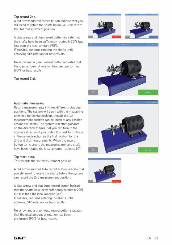
Tap record 2nd.A red arrow and red record button indicate that you still need to rotate the shafts before you can record the 3rd measurement position.
A blue arrow and blue record button indicate that the shafts have been suficiently rotated (>20°), but less than the ideal amount (90°). If possible, continue rotating the shafts until achieving 90° rotation for best results.
No arrow and a green record button indicates that the ideal amount of rotation has been performed (90°) for best results.
Tap record 3rd.
Automatic measuringRecord measurements in three different rotational positions. The system will begin with the measuring units in a horizontal position, though the 1st measurement position can be taken at any position around the shafts. The system will offer guidance on the direction to turn, but you can turn in the opposite direction if you prefer. It is best to continue in the same direction as the irst rotation for the 2nd and 3rd measurements. When the record button turns green, the measuring unit and shaft have been rotated the ideal amount – at least 90°.
Tap start auto. This records the 1st measurement position.
A red arrow and red Auto record button indicate that you still need to rotate the shafts before the system can record the 2nd measurement position.
A blue arrow and blue Auto record button indicate that the shafts have been suficiently rotated (>20°), but less than the ideal amount (90°). If possible, continue rotating the shafts until achieving 90° rotation for best results.
No arrow and a green Auto record button indicates that the ideal amount of rotation has been performed (90°) for best results.
12 EN
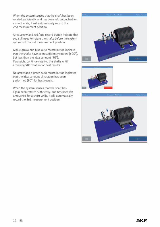
When the system senses that the shaft has been rotated suficiently, and has been left untouched for a short while, it will automatically record the 2nd measurement position.
A red arrow and red Auto record button indicate that you still need to rotate the shafts before the system can record the 3rd measurement position.
A blue arrow and blue Auto record button indicate that the shafts have been suficiently rotated (>20°), but less than the ideal amount (90°). If possible, continue rotating the shafts until achieving 90° rotation for best results.
No arrow and a green Auto record button indicates that the ideal amount of rotation has been performed (90°) for best results.
When the system senses that the shaft has again been rotated suficiently, and has been left untouched for a short while, it will automatically record the 3rd measurement position.
13EN
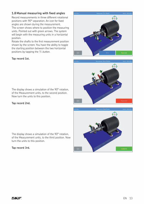
1.8 Manual measuring with fixed angles
Record measurements in three different rotational positions with 90° separation. An icon for ixed angles are shown during the measurement. The screen shows where to position the measuring units. Pointed out with green arrows. The system will begin with the measuring units in a horizontal position.Rotate the shafts to the irst measurement position shown by the screen. You have the ability to toggle the starting position between the two horizontal positions by tapping the 9/3 button.
Tap record 1st.
The display shows a simulation of the 90° rotation, of the Measurement units, to the second position. Now turn the units to this position.
Tap record 2nd.
The display shows a simulation of the 90° rotation, of the Measurement units, to the third position. Now turn the units to this position.
Tap record 3rd.
14 EN
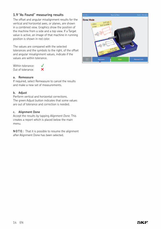
1.9 “As Found” measuring results
The offset and angular misalignment results for the vertical and horizontal axes, or planes, are shown in a combined view. Graphics show the position of the machine from a side and a top view. If a Target value is active, an image of that machine in running position is shown in red color.
The values are compared with the selected tolerances and the symbols to the right, of the offset and angular misalignment values, indicate if the values are within tolerance.
Within tolerance: √Out of tolerance: ×
a. RemeasureIf required, select Remeasure to cancel the results and make a new set of measurements.
b. AdjustPerform vertical and horizontal corrections. The green Adjust button indicates that some values are out of tolerance and correction is needed.
c. Alignment DoneAccept the results by tapping Alignment Done. This creates a report which is placed below the main menu.
N OT E : That it is possible to resume the alignment after Alignment Done has been selected.
15EN
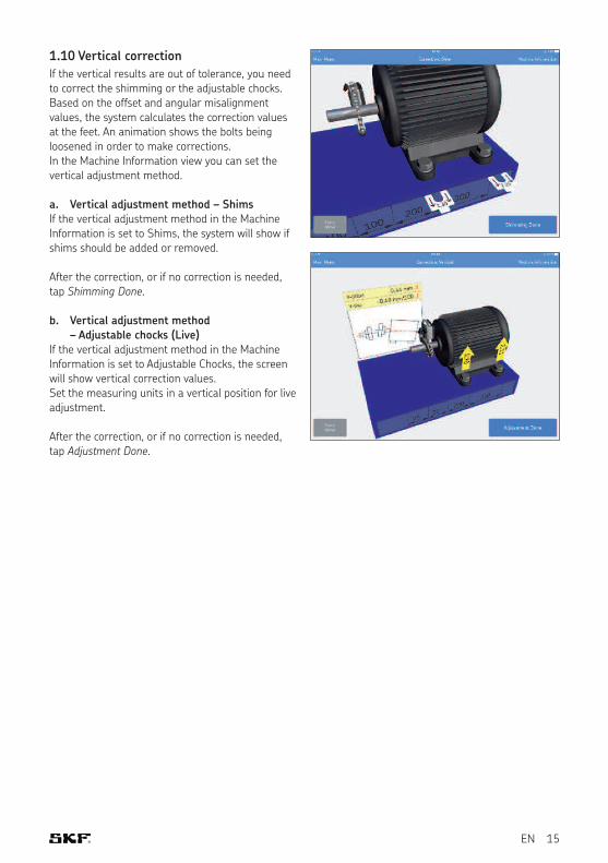
1.10 Vertical correction
If the vertical results are out of tolerance, you need to correct the shimming or the adjustable chocks. Based on the offset and angular misalignment values, the system calculates the correction values at the feet. An animation shows the bolts being loosened in order to make corrections. In the Machine Information view you can set the vertical adjustment method.
a. Vertical adjustment method – ShimsIf the vertical adjustment method in the Machine Information is set to Shims, the system will show if shims should be added or removed.
After the correction, or if no correction is needed, tap Shimming Done.
b. Vertical adjustment method – Adjustable chocks (Live)
If the vertical adjustment method in the Machine Information is set to Adjustable Chocks, the screen will show vertical correction values. Set the measuring units in a vertical position for live adjustment.
After the correction, or if no correction is needed, tap Adjustment Done.
16 EN
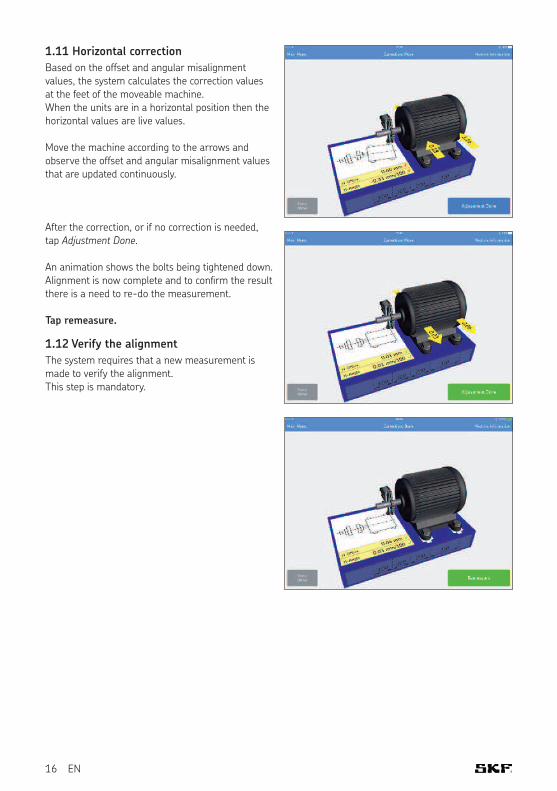
1.11 Horizontal correction
Based on the offset and angular misalignment values, the system calculates the correction values at the feet of the moveable machine. When the units are in a horizontal position then the horizontal values are live values.
Move the machine according to the arrows and observe the offset and angular misalignment values that are updated continuously.
After the correction, or if no correction is needed, tap Adjustment Done.
An animation shows the bolts being tightened down. Alignment is now complete and to conirm the result there is a need to re-do the measurement.
Tap remeasure.
1.12 Verify the alignment
The system requires that a new measurement is made to verify the alignment. This step is mandatory.
17EN
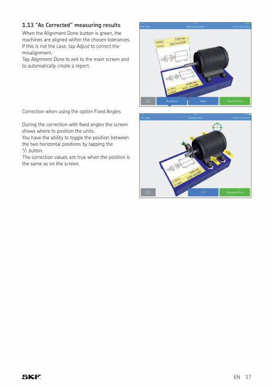
1.13 “As Corrected” measuring results
When the Alignment Done button is green, the machines are aligned within the chosen tolerances. If this is not the case, tap Adjust to correct the misalignment.Tap Alignment Done to exit to the main screen and to automatically create a report.
Correction when using the option Fixed Angles
During the correction with ixed angles the screen shows where to position the units.You have the ability to toggle the position between the two horizontal positions by tapping the 9/3 button.The correction values are true when the position is the same as on the screen.
18 EN
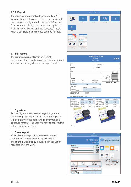
1.14 Report
The reports are automatically generated as PDF i les and they are displayed on the main menu, with the most recent alignment in the upper left corner. A report automatically contains measuring data for both the “As Found” and “As Corrected” results when a complete alignment has been performed.
a. Edit reportThe report contains information from the measurement and can be completed with additional information. Tap anywhere in the report to edit.
b. SignatureTap the Signature fi eld and write your signature in the opening Sign Report view. If a signed report is to be edited then the editor will be informed of a signature removal. The user will have to coni rm this before editing is possible.
c. Share reportWhile viewing a report it is possible to share it through for instance email or by printing it. The sharing functionality is available in the upper right corner of the view.
Shaft Alignment Report
Horizontal
Report Name
Machine ID Date
04/05/17 11:26
Company Operator
Notes
100100 200 300
Tolerances
Speed
(rpm)
Offset
(mm)
Angular Error
(mm/100)
0000-1000 0,13 0,10
Target Values
Vertical Horizontal
Offset (mm) - -
Angle (mm/100) - -Angle (mm/100)
Stationary Unit (S):
Movable Unit (M):
Soft Foot Check Performed:
Demo 1
Demo 2
No
Result
✗As Found Vertical Horizontal
Offset (mm) ✓-0,07 ✗0,15
Angle (mm/100) ✗0,17 ✗0,10
Front Feet (mm) 0,45 0,45
Rear Feet (mm) 0,98 0,75
✓As Corrected Vertical Horizontal
Offset (mm) ✓0,00 ✓0,00
Angle (mm/100) ✓0,00 ✓0,00
Front Feet (mm) 0,00 0,00
Rear Feet (mm) 0,00 0,00
Signature
...............................................................
19EN
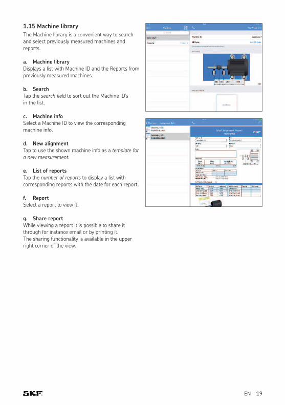
1.15 Machine library
The Machine library is a convenient way to search and select previously measured machines and reports.
a. Machine libraryDisplays a list with Machine ID and the Reports from previously measured machines.
b. SearchTap the search field to sort out the Machine ID’s in the list.
c. Machine infoSelect a Machine ID to view the corresponding machine info.
d. New alignmentTap to use the shown machine info as a template for a new measurement.
e. List of reportsTap the number of reports to display a list with corresponding reports with the date for each report.
f. ReportSelect a report to view it.
g. Share reportWhile viewing a report it is possible to share it through for instance email or by printing it. The sharing functionality is available in the upper right corner of the view.

20


skf.com | mapro.skf.com | skf.com/mount | skf.com/alignment
® SKF is a registered trademark of the SKF Group. App Store is a service mark of Apple Inc. registered in the US and other countries. Android and Google Play are trademarks of Google Inc.
© SKF Group 2018The contents of this publication are the copyright of the publisher and may not be reproduced (even extracts) unless prior written permission is granted. Every care has been taken to ensure the accuracy of the information contained in this publication but no liability can be accepted for any loss or damage whether direct, indirect or consequential arising out of the use of the information contained herein.
MP5465 EN · 2018/02