SKF Oil+Air Lubrication Units and Mixing Valves Product...
28
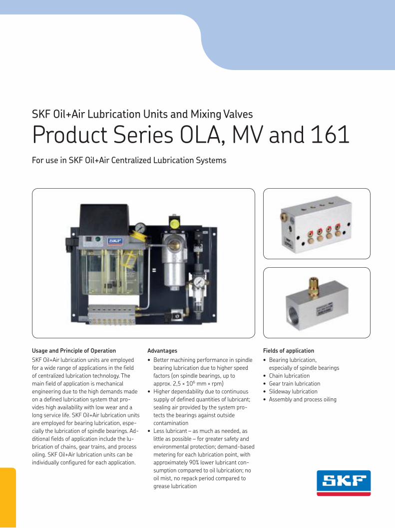
Usage and Principle of Operation SKF Oil+Air lubrication units are employed for a wide range of applications in the field of centralized lubrication technology. The main field of application is mechanical engineering due to the high demands made on a defined lubrication system that pro- vides high availability with low wear and a long service life. SKF Oil+Air lubrication units are employed for bearing lubrication, espe- cially the lubrication of spindle bearings. Ad- ditional fields of application include the lu- brication of chains, gear trains, and process oiling. SKF Oil+Air lubrication units can be individually configured for each application. Advantages • Better machining performance in spindle bearing lubrication due to higher speed factors (on spindle bearings, up to approx. 2,5 × 10 6 mm × rpm) • Higher dependability due to continuous supply of defined quantities of lubricant; sealing air provided by the system pro- tects the bearings against outside contamination • Less lubricant – as much as needed, as little as possible – for greater safety and environmental protection; demand-based metering for each lubrication point, with approximately 90% lower lubricant con- sumption compared to oil lubrication; no oil mist, no repack period compared to grease lubrication Fields of application • Bearing lubrication, especially of spindle bearings • Chain lubrication • Gear train lubrication • Slideway lubrication • Assembly and process oiling SKF Oil+Air Lubrication Units and Mixing Valves Product Series OLA, MV and 161 For use in SKF Oil+Air Centralized Lubrication Systems
Transcript of SKF Oil+Air Lubrication Units and Mixing Valves Product...
Usage and Principle of Operation
SKF Oil+Air lubrication units are employed
for a wide range of applications in the field
of centralized lubrication technology. The
main field of application is mechanical
engineering due to the high demands made
on a defined lubrication system that pro-
vides high availability with low wear and a
long service life. SKF Oil+Air lubrication units
are employed for bearing lubrication, espe-
cially the lubrication of spindle bearings. Ad-
ditional fields of application include the lu-
brication of chains, gear trains, and process
oiling. SKF Oil+Air lubrication units can be
individually configured for each application.
Advantages
• Better machining performance in spindle
bearing lubrication due to higher speed
factors (on spindle bearings, up to
approx. 2,5 × 106 mm × rpm)
• Higher dependability due to continuous
supply of defined quantities of lubricant;
sealing air provided by the system pro-
tects the bearings against outside
contamination
• Less lubricant – as much as needed, as
little as possible – for greater safety and
environmental protection; demand-based
metering for each lubrication point, with
approximately 90% lower lubricant con-
sumption compared to oil lubrication; no
oil mist, no repack period compared to
grease lubrication
Fields of application
• Bearing lubrication,
especially of spindle bearings
• Chain lubrication
• Gear train lubrication
• Slideway lubrication
• Assembly and process oiling
SKF Oil+Air Lubrication Units and Mixing Valves
Product Series OLA, MV and 161For use in SKF Oil+Air Centralized Lubrication Systems
PU
B L
S/P
2 1
3220 E
N · 1
-5012-3-EN
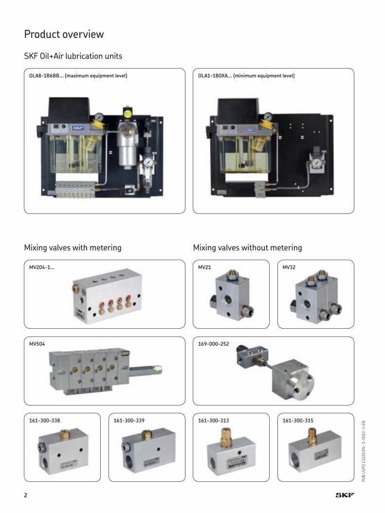
MV204-1...
OLA1-1B0XA... (minimum equipment level)
MV504
161-300-338
OLA8-1B6BB... (maximum equipment level)
Product overview
SKF Oil+Air lubrication units
Mixing valves with metering Mixing valves without metering
161-300-313
MV21
169-000-252
161-300-339 161-300-315
MV32
2
PU
B L
S/P
2 1
3220 E
N · 1
-5012-3-EN
SKF Oil+Air Lubrication Units and Mixing Valves
Contents
Product overview . . . . . . . . . . . . . . . . . . . . . . . . . . . . . . . . . . 2
Product selection table . . . . . . . . . . . . . . . . . . . . . . . . . . . . . 3
Fundamentals
SKF Oil+Air lubrication systems . . . . . . . . . . . . . . . . . . . . . . 4
Components of oil+air lubrication systems . . . . . . . . . . . . . 4
Principles of oil+air lubrication - example: rolling bearings . 5
Lubricant quantities . . . . . . . . . . . . . . . . . . . . . . . . . . . . . . 5
Requirements for compressed air . . . . . . . . . . . . . . . . . . . . 6
Requirements for lubricant . . . . . . . . . . . . . . . . . . . . . . . . . 6
Lubricant feed lines (criteria, bearing type) . . . . . . . . . . . . . 7
SKF Oil+Air lubrication units
Designs . . . . . . . . . . . . . . . . . . . . . . . . . . . . . . . . . . . . . . . 8
Configurator, order example . . . . . . . . . . . . . . . . . . . . . . . . 9
Dimensions . . . . . . . . . . . . . . . . . . . . . . . . . . . . . . . . . . . . 10
Technical data . . . . . . . . . . . . . . . . . . . . . . . . . . . . . . . . . . 11
Hydraulic layouts . . . . . . . . . . . . . . . . . . . . . . . . . . . . . . . . 12
Spare parts . . . . . . . . . . . . . . . . . . . . . . . . . . . . . . . . . 22-23
SKF Oil+Air mixing valves with metering
MV20x-1... / MV30x-1... . . . . . . . . . . . . . . . . . . . . . . 13–14
MV50x . . . . . . . . . . . . . . . . . . . . . . . . . . . . . . . . . . . . . . . 15
161-300-338 / 161-300-339 . . . . . . . . . . . . . . . . . . . . . 16
SKF Oil+Air mixing valves without metering
161-300-313 / 161-300-315 . . . . . . . . . . . . . . . . . . . . . 17
MV21–MV38 . . . . . . . . . . . . . . . . . . . . . . . . . . . . . . . . . . . 18
SKF Oil+Air flow dividers
169-000-18x / 169-000-25x . . . . . . . . . . . . . . . . . . . . . 19
Accessories
Hose coils, directional control valves,
pressurized air control valves . . . . . . . . . . . . . . . . . . . . . . 20
Nozzles, pressure switches,
differential pressure switches . . . . . . . . . . . . . . . . . . . . . . 21
Electrical connections, fittings . . . . . . . . . . . . . . . . . . . . . . 22
Tubing, pressure filters, oil-streak sensors . . . . . . . . . . . . 23
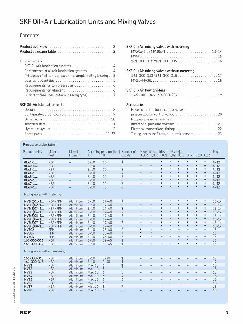
Product selection table
Product series Material Material Actuating pressure [bar] Number of Metered quantities [cm³/cycle] Page Seal Housing Air Oil outlets 0,002 0,006 0,01 0,02 0,03 0,06 0,10 0,16
OLA1-1... NBR – 3–10 30 1 – – • • • • • • 8–12OLA2-1... NBR – 3–10 30 2 – – • • • • • • 8–12OLA3-1... NBR – 3–10 30 3 – – • • • • • • 8–12OLA4-1... NBR – 3–10 30 4 – – • • • • • • 8–12OLA5-1... NBR – 3–10 30 5 – – • • • • • • 8–12OLA6-1... NBR – 3–10 30 6 – – • • • • • • 8–12OLA7-1... NBR – 3–10 30 7 – – • • • • • • 8–12OLA8-1... NBR – 3–10 30 8 – – • • • • • • 8–12
Mixing valves with metering
MV2(3)01-1... NBR / FPM Aluminum 3–10 17–40 1 – – • • • • • • 13–14MV2(3)02-1... NBR / FPM Aluminum 3–10 17–40 2 – – • • • • • • 13–14MV2(3)03-1... NBR / FPM Aluminum 3–10 17–40 3 – – • • • • • • 13–14MV2(3)04-1... NBR / FPM Aluminum 3–10 17–40 4 – – • • • • • • 13–14MV2(3)05-1... NBR / FPM Aluminum 3–10 17–40 5 – – • • • • • • 13–14MV2(3)06-1... NBR / FPM Aluminum 3–10 17–40 6 – – • • • • • • 13–14MV2(3)07-1... NBR / FPM Aluminum 3–10 17–40 7 – – • • • • • • 13–14MV2(3)08-1... NBR / FPM Aluminum 3–10 17–40 8 – – • • • • • • 13–14MV502 FPM Aluminum 3–10 25–40 2 • • – – – – – – 15MV504 FPM Aluminum 3–10 25–40 4 • • – – – – – – 15MV506 FPM Aluminum 3–10 25–40 6 • • – – – – – – 15161-300-338 NBR Aluminum 3–10 12–45 1 – – – – • • • – 16161-300-339 NBR Aluminum 3–10 12–45 1 – – – – • • • – 16
Mixing valves without metering
161-300-313 NBR Aluminum 3–10 3–40 1 – – – – – – – – 17161-300-315 NBR Aluminum 3–10 3–40 1 – – – – – – – – 17MV21 NBR Aluminum Max. 10 5 1 – – – – – – – – 18MV32 NBR Aluminum Max. 10 5 2 – – – – – – – – 18MV33 NBR Aluminum Max. 10 5 3 – – – – – – – – 18MV34 NBR Aluminum Max. 10 5 4 – – – – – – – – 18MV35 NBR Aluminum Max. 10 5 5 – – – – – – – – 18MV36 NBR Aluminum Max. 10 5 6 – – – – – – – – 18MV37 NBR Aluminum Max. 10 5 7 – – – – – – – – 18MV38 NBR Aluminum Max. 10 5 8 – – – – – – – – 18
3
PU
B L
S/P
2 1
3220 E
N · 1
-5012-3-EN
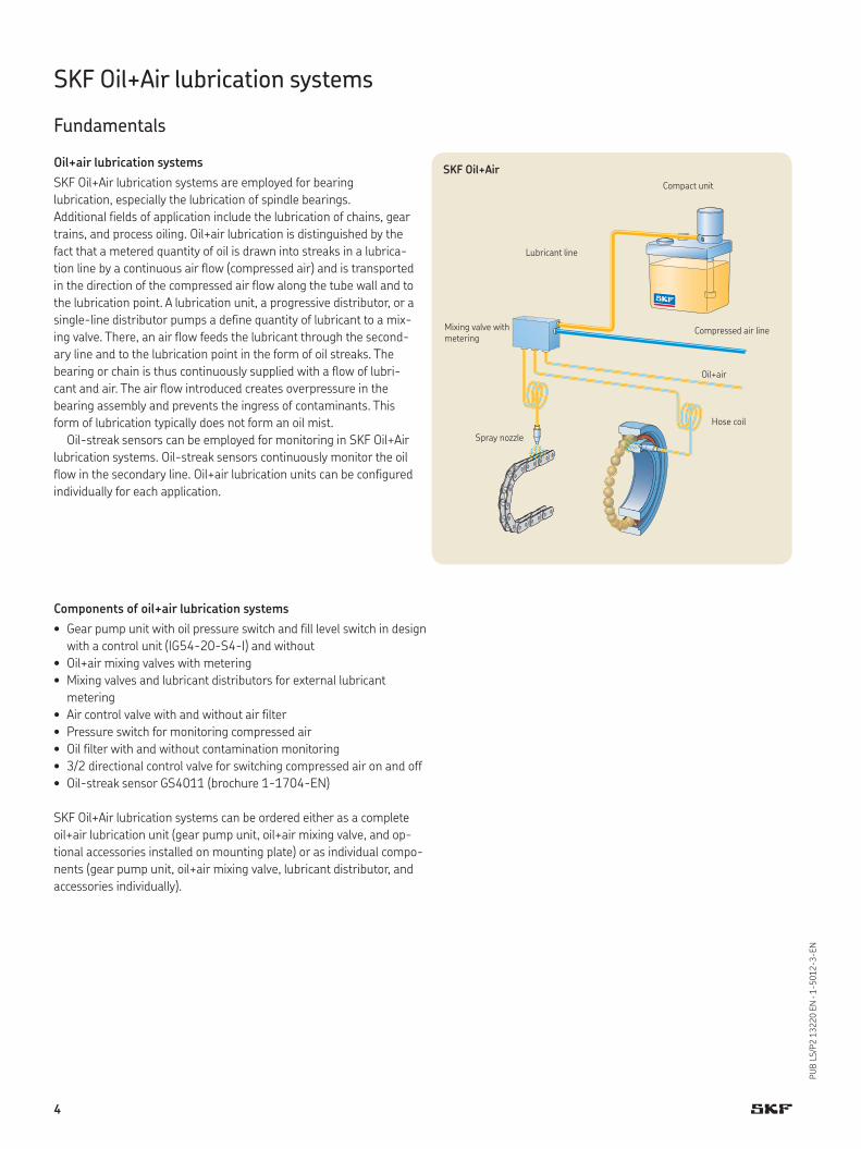
SKF Oil+Air lubrication systems
Fundamentals
Oil+air lubrication systems
SKF Oil+Air lubrication systems are employed for bearing
lubrication, especially the lubrication of spindle bearings.
Additional fields of application include the lubrication of chains, gear
trains, and process oiling. Oil+air lubrication is distinguished by the
fact that a metered quantity of oil is drawn into streaks in a lubrica-
tion line by a continuous air flow (compressed air) and is transported
in the direction of the compressed air flow along the tube wall and to
the lubrication point. A lubrication unit, a progressive distributor, or a
single-line distributor pumps a define quantity of lubricant to a mix-
ing valve. There, an air flow feeds the lubricant through the second-
ary line and to the lubrication point in the form of oil streaks. The
bearing or chain is thus continuously supplied with a flow of lubri-
cant and air. The air flow introduced creates overpressure in the
bearing assembly and prevents the ingress of contaminants. This
form of lubrication typically does not form an oil mist.
Oil-streak sensors can be employed for monitoring in SKF Oil+Air
lubrication systems. Oil-streak sensors continuously monitor the oil
flow in the secondary line. Oil+air lubrication units can be configured
individually for each application.
Mixing valve with
meteringCompressed air line
Oil+air
Lubricant line
Compact unit
Spray nozzle
Hose coil
SKF Oil+Air
Components of oil+air lubrication systems
• Gear pump unit with oil pressure switch and fill level switch in design
with a control unit (IG54-20-S4-I) and without
• Oil+air mixing valves with metering
• Mixing valves and lubricant distributors for external lubricant
metering
• Air control valve with and without air filter
• Pressure switch for monitoring compressed air
• Oil filter with and without contamination monitoring
• 3/2 directional control valve for switching compressed air on and off
• Oil-streak sensor GS4011 (brochure 1-1704-EN)
SKF Oil+Air lubrication systems can be ordered either as a complete
oil+air lubrication unit (gear pump unit, oil+air mixing valve, and op-
tional accessories installed on mounting plate) or as individual compo-
nents (gear pump unit, oil+air mixing valve, lubricant distributor, and
accessories individually).
4
PU
B L
S/P
2 1
3220 E
N · 1
-5012-3-EN
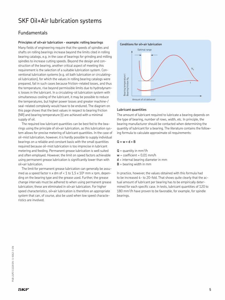
Principles of oil+air lubrication - example: rolling bearings
Many fields of engineering require that the speeds of spindles and
shafts on rolling bearings increase beyond the limits cited in rolling
bearing catalogs, e.g. in the case of bearings for grinding and milling
spindles to increase cutting speeds. Beyond the design and con-
struction of the bearing, another critical aspect of meeting this
requirement is the selection of a suitable lubrication system. Con-
ventional lubrication systems (e.g. oil bath lubrication or circulating-
oil lubrication), for which the values in rolling bearing catalogs were
prepared, fail in such cases because friction-related losses, and thus
the temperature, rise beyond permissible limits due to hydrodynam-
ic losses in the lubricant. In a circulating-oil lubrication system with
simultaneous cooling of the lubricant, it may be possible to reduce
the temperatures, but higher power losses and greater machine-/
seal-related complexity would have to be endured. The diagram on
this page shows that the best values in respect to bearing friction
(NR) and bearing temperature (t) are achieved with a minimal
supply of oil.
The required low lubricant quantities can be best fed to the bea-
rings using the principle of oil+air lubrication, as this lubrication sys-
tem allows for precise metering of lubricant quantities. In the case of
oil-mist lubrication, however, it is hardly possible to supply individual
bearings on a reliable and constant basis with the small quantities
required because oil-mist lubrication is too imprecise in lubricant
metering and feeding. Permanent grease lubrication is well suited
and often employed. However, the limit on speed factors achievable
using permanent grease lubrication is significantly lower than with
oil+air lubrication.
The limit for permanent grease lubrication can generally be assu-
med as a speed factor n x dm of < 1 to 1,5 x 106 mm x rpm, depen-
ding on the bearing type and the grease used. Further, the grease
change intervals must be adhered to when using permanent grease
lubrication; these are eliminated in oil+air lubrication. For higher
speed characteristics, oil+air lubrication is therefore an appropriate
system that can, of course, also be used when low speed characte-
ristics are involved.
Optimal range
Amount of oil delivered
Beari
ng tem
pera
ture
t
Beari
ng fri
ctio
n N
R
SKF Oil+Air lubrication systems
Fundamentals
Lubricant quantities
The amount of lubricant required to lubricate a bearing depends on
the type of bearing, number of rows, width, etc. In principle, the
bearing manufacturer should be contacted when determining the
quantity of lubricant for a bearing. The literature contains the follow-
ing formula to calculate approximate oil requirements:
Q = w × d × B
Q = quantity in mm3/h
w = coefficient = 0,01 mm/h
d = internal bearing diameter in mm
B = bearing width in mm
In practice, however, the values obtained with this formula had
to be increased 4- to 20-fold. That shows quite clearly that the ac-
tual amount of lubricant per bearing has to be empirically deter-
mined for each specific case. In tests, lubricant quantities of 120 to
180 mm3/h have proven to be favorable, for example, for spindle
bearings.
Conditions for oil+air lubrication
5
PU
B L
S/P
2 1
3220 E
N · 1
-5012-3-EN
SKF Oil+Air lubrication systems
Fundamentals
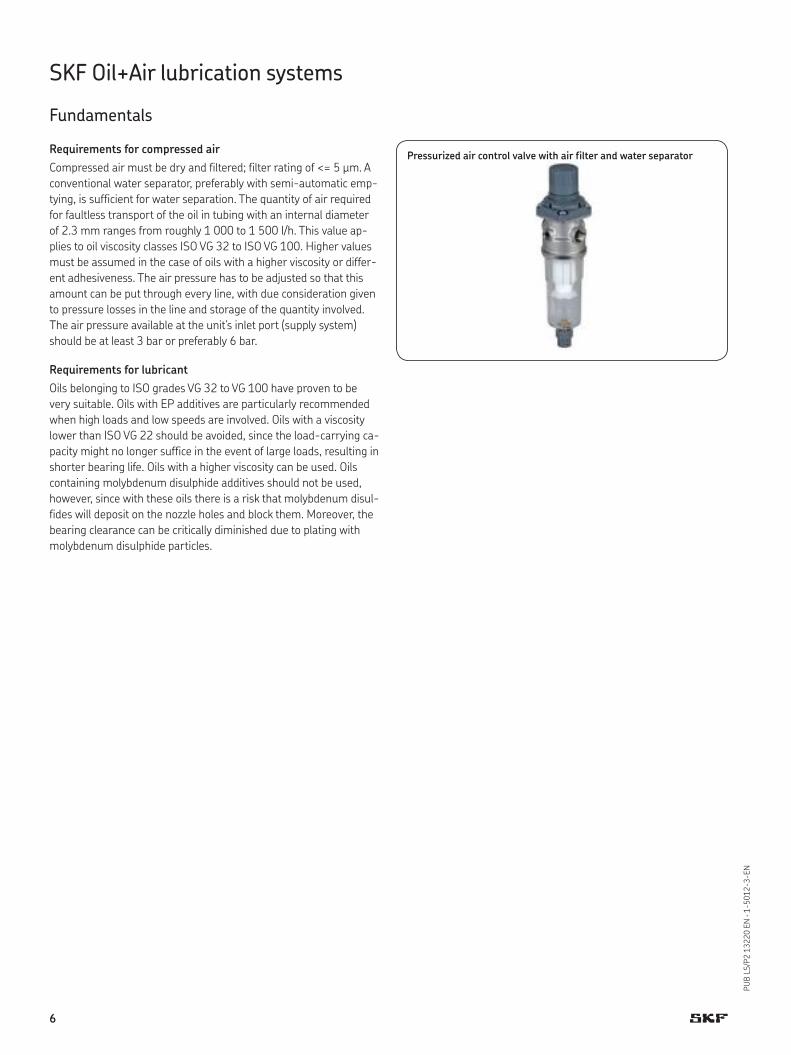
Requirements for compressed air
Compressed air must be dry and filtered; filter rating of <= 5 μm. A
conventional water separator, preferably with semi-automatic emp-
tying, is sufficient for water separation. The quantity of air required
for faultless transport of the oil in tubing with an internal diameter
of 2.3 mm ranges from roughly 1 000 to 1 500 I/h. This value ap-
plies to oil viscosity classes ISO VG 32 to ISO VG 100. Higher values
must be assumed in the case of oils with a higher viscosity or differ-
ent adhesiveness. The air pressure has to be adjusted so that this
amount can be put through every line, with due consideration given
to pressure losses in the line and storage of the quantity involved.
The air pressure available at the unit’s inlet port (supply system)
should be at least 3 bar or preferably 6 bar.
Requirements for lubricant
Oils belonging to ISO grades VG 32 to VG 100 have proven to be
very suitable. Oils with EP additives are particularly recommended
when high loads and low speeds are involved. Oils with a viscosity
lower than ISO VG 22 should be avoided, since the load-carrying ca-
pacity might no longer suffice in the event of large loads, resulting in
shorter bearing life. Oils with a higher viscosity can be used. Oils
containing molybdenum disulphide additives should not be used,
however, since with these oils there is a risk that molybdenum disul-
fides will deposit on the nozzle holes and block them. Moreover, the
bearing clearance can be critically diminished due to plating with
molybdenum disulphide particles.
Pressurized air control valve with air filter and water separator
6
PU
B L
S/P
2 1
3220 E
N · 1
-5012-3-EN
SKF Oil+Air lubrication systems
Fundamentals
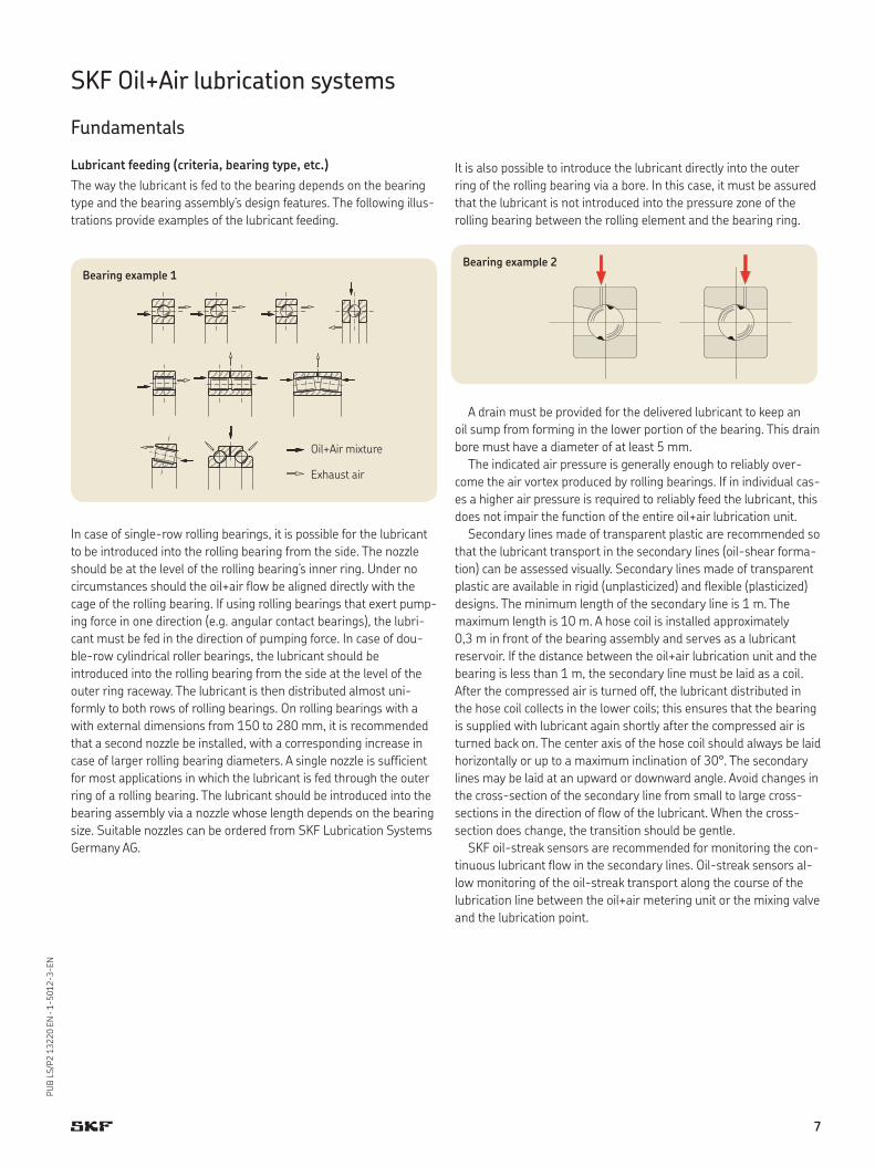
Lubricant feeding (criteria, bearing type, etc.)
The way the lubricant is fed to the bearing depends on the bearing
type and the bearing assembly’s design features. The following illus-
trations provide examples of the lubricant feeding.
In case of single-row rolling bearings, it is possible for the lubricant
to be introduced into the rolling bearing from the side. The nozzle
should be at the level of the rolling bearing’s inner ring. Under no
circumstances should the oil+air flow be aligned directly with the
cage of the rolling bearing. If using rolling bearings that exert pump-
ing force in one direction (e.g. angular contact bearings), the lubri-
cant must be fed in the direction of pumping force. In case of dou-
ble-row cylindrical roller bearings, the lubricant should be
introduced into the rolling bearing from the side at the level of the
outer ring raceway. The lubricant is then distributed almost uni-
formly to both rows of rolling bearings. On rolling bearings with a
with external dimensions from 150 to 280 mm, it is recommended
that a second nozzle be installed, with a corresponding increase in
case of larger rolling bearing diameters. A single nozzle is sufficient
for most applications in which the lubricant is fed through the outer
ring of a rolling bearing. The lubricant should be introduced into the
bearing assembly via a nozzle whose length depends on the bearing
size. Suitable nozzles can be ordered from SKF Lubrication Systems
Germany AG.
It is also possible to introduce the lubricant directly into the outer
ring of the rolling bearing via a bore. In this case, it must be assured
that the lubricant is not introduced into the pressure zone of the
rolling bearing between the rolling element and the bearing ring.
A drain must be provided for the delivered lubricant to keep an
oil sump from forming in the lower portion of the bearing. This drain
bore must have a diameter of at least 5 mm.
The indicated air pressure is generally enough to reliably over-
come the air vortex produced by rolling bearings. If in individual cas-
es a higher air pressure is required to reliably feed the lubricant, this
does not impair the function of the entire oil+air lubrication unit.
Secondary lines made of transparent plastic are recommended so
that the lubricant transport in the secondary lines (oil-shear forma-
tion) can be assessed visually. Secondary lines made of transparent
plastic are available in rigid (unplasticized) and flexible (plasticized)
designs. The minimum length of the secondary line is 1 m. The
maximum length is 10 m. A hose coil is installed approximately
0,3 m in front of the bearing assembly and serves as a lubricant
reservoir. If the distance between the oil+air lubrication unit and the
bearing is less than 1 m, the secondary line must be laid as a coil.
After the compressed air is turned off, the lubricant distributed in
the hose coil collects in the lower coils; this ensures that the bearing
is supplied with lubricant again shortly after the compressed air is
turned back on. The center axis of the hose coil should always be laid
horizontally or up to a maximum inclination of 30°. The secondary
lines may be laid at an upward or downward angle. Avoid changes in
the cross-section of the secondary line from small to large cross-
sections in the direction of flow of the lubricant. When the cross-
section does change, the transition should be gentle.
SKF oil-streak sensors are recommended for monitoring the con-
tinuous lubricant flow in the secondary lines. Oil-streak sensors al-
low monitoring of the oil-streak transport along the course of the
lubrication line between the oil+air metering unit or the mixing valve
and the lubrication point.
Bearing example 1
Oil+Air mixture
Exhaust air
Bearing example 2
7

PU
B L
S/P
2 1
3220 E
N · 1
-5012-3-EN
SKF Oil+Air lubrication unit – OLA
Designs
Pressure switch for minimum air pressure
Gear pump unit with control unit
Gear pump unit without control unit
Oil filters with monitoring
3/2 directional air control valve
Oil filters without monitoring
! Note
This page shows possible designs
of the oil+air lubrication units.
The configurator on the following
page allows the functional specification
of a unit with associated order number.
Minimal designMaximum design
SKF plug connectors
Solderless tube union
Mixing valve with meteringcompressed air control valve with air filter and water seperator
Air control valve without air filter
8
PU
B L
S/P
2 1
3220 E
N · 1
-5012-3-EN
SKF Oil+Air lubrication unit – OLA
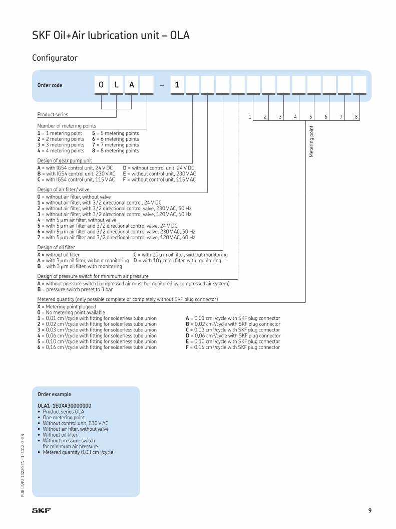
Configurator
Order example
OLA1-1E0XA30000000• Product series OLA • One metering point• Without control unit, 230 V AC• Without air filter, without valve• Without oil filter • Without pressure switch
for minimum air pressure• Metered quantity 0,03 cm³/cycle
Order code O L A – 1
2 3 4 5 6 7 8Product series
1
Number of metering points
1 = 1 metering point2 = 2 metering points3 = 3 metering points4 = 4 metering points
5 = 5 metering points6 = 6 metering points7 = 7 metering points8 = 8 metering points
Design of gear pump unit
A = with IG54 control unit, 24 V DCB = with IG54 control unit, 230 V ACC = with IG54 control unit, 115 V AC
D = without control unit, 24 V DCE = without control unit, 230 V ACF = without control unit, 115 V AC
Design of air filter / valve
0 = without air filter, without valve1 = without air filter, with 3 / 2 directional control, 24 V DC2 = without air filter, with 3 / 2 directional control valve, 230 V AC, 50 Hz3 = without air filter, with 3 / 2 directional control valve, 120 V AC, 60 Hz4 = with 5 m air filter, without valve5 = with 5 m air filter and 3 / 2 directional control valve, 24 V DC6 = with 5 m air filter and 3 / 2 directional control valve, 230 V AC, 50 Hz7 = with 5 m air filter and 3 / 2 directional control valve, 120 V AC, 60 Hz
Design of oil filter
X = without oil filterA = with 3 m oil filter, without monitoringB = with 3 m oil filter, with monitoring
C = with 10 m oil filter, without monitoringD = with 10 m oil filter, with monitoring
Design of pressure switch for minimum air pressure
A = without pressure switch (compressed air must be monitored by compressed air system)B = pressure switch preset to 3 bar
Metered quantity (only possible complete or completely without SKF plug connector)
X = Metering point plugged0 = No metering point available1 = 0,01 cm³/cycle with fitting for solderless tube union2 = 0,02 cm³/cycle with fitting for solderless tube union3 = 0,03 cm³/cycle with fitting for solderless tube union4 = 0,06 cm³/cycle with fitting for solderless tube union5 = 0,10 cm³/cycle with fitting for solderless tube union6 = 0,16 cm³/cycle with fitting for solderless tube union
A = 0,01 cm³/cycle with SKF plug connectorB = 0,02 cm³/cycle with SKF plug connectorC = 0,03 cm³/cycle with SKF plug connectorD = 0,06 cm³/cycle with SKF plug connectorE = 0,10 cm³/cycle with SKF plug connectorF = 0,16 cm³/cycle with SKF plug connector
Mete
ring p
oin
t
9
PU
B L
S/P
2 1
3220 E
N · 1
-5012-3-EN
SKF Oil+Air lubrication unit – OLA
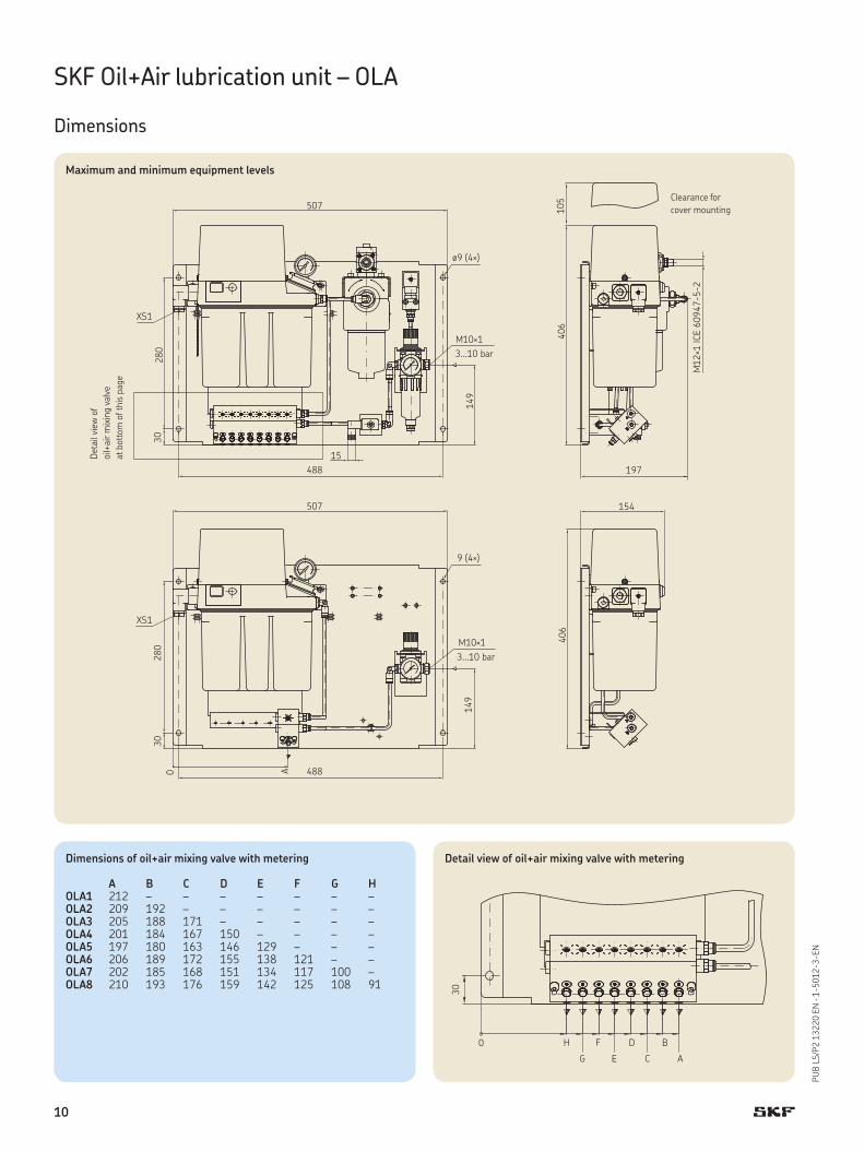
Dimensions
Maximum and minimum equipment levels
Dimensions of oil+air mixing valve with metering
A B C D E F G HOLA1 212 – – – – – – –OLA2 209 192 – – – – – –OLA3 205 188 171 – – – – –OLA4 201 184 167 150 – – – –OLA5 197 180 163 146 129 – – –OLA6 206 189 172 155 138 121 – –OLA7 202 185 168 151 134 117 100 –OLA8 210 193 176 159 142 125 108 91
Deta
il vie
w o
f
oil+
air m
ixin
g v
alv
e
at bott
om
of th
is p
age
Clearance for
cover mounting
Detail view of oil+air mixing valve with metering
10
PU
B L
S/P
2 1
3220 E
N · 1
-5012-3-EN
SKF Oil+Air lubrication unit – OLA
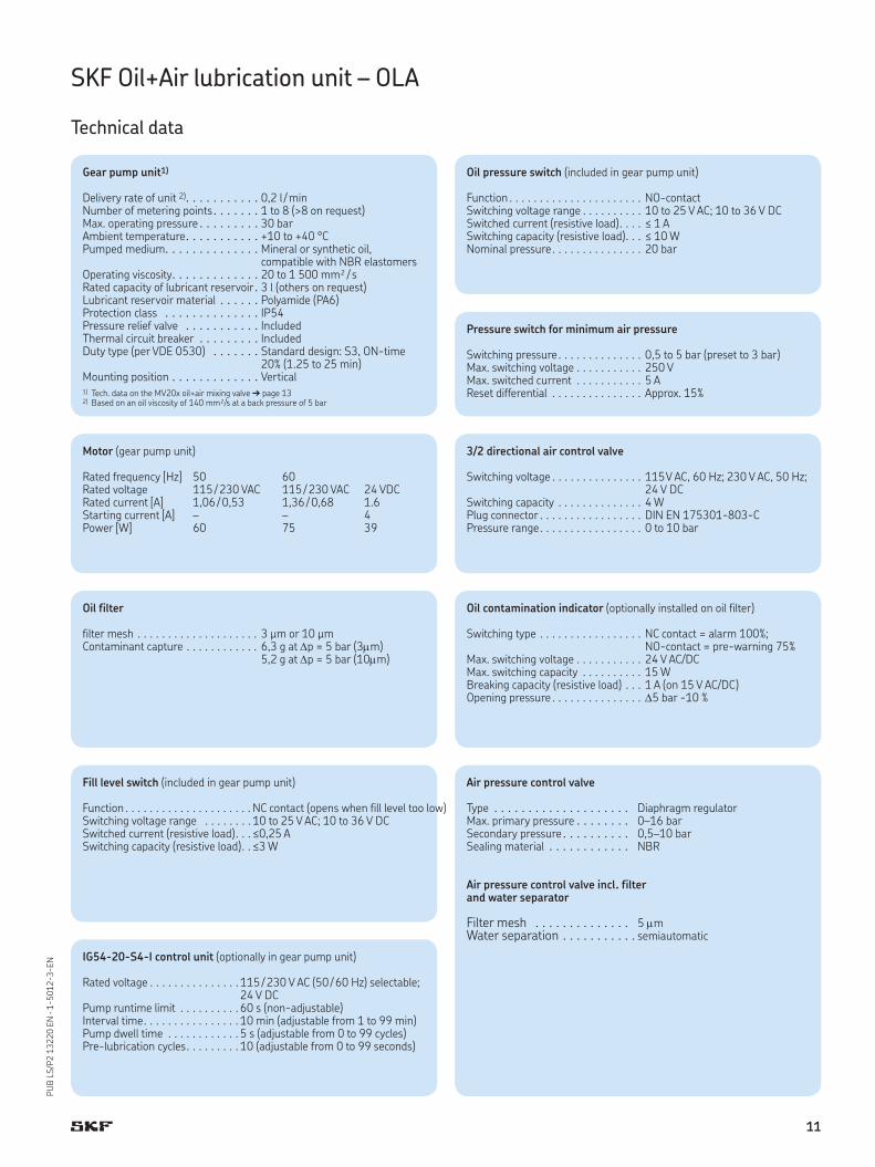
Technical data
Gear pump unit1)
Delivery rate of unit 2) . . . . . . . . . . . 0,2 l / minNumber of metering points . . . . . . . 1 to 8 (>8 on request)Max. operating pressure . . . . . . . . . 30 barAmbient temperature . . . . . . . . . . . +10 to +40 °CPumped medium . . . . . . . . . . . . . . Mineral or synthetic oil,
compatible with NBR elastomersOperating viscosity . . . . . . . . . . . . . 20 to 1 500 mm² / sRated capacity of lubricant reservoir . 3 l (others on request)Lubricant reservoir material . . . . . . Polyamide (PA6)Protection class . . . . . . . . . . . . . . IP54Pressure relief valve . . . . . . . . . . . IncludedThermal circuit breaker . . . . . . . . . IncludedDuty type (per VDE 0530) . . . . . . . Standard design: S3, ON-time
20% (1.25 to 25 min)Mounting position . . . . . . . . . . . . . Vertical
Motor (gear pump unit)
Rated frequency [Hz] 50 60Rated voltage 115 / 230 VAC 115 / 230 VAC 24 VDCRated current [A] 1,06 / 0,53 1,36 / 0,68 1.6Starting current [A] – – 4Power [W] 60 75 39
Pressure switch for minimum air pressure
Switching pressure . . . . . . . . . . . . . . 0,5 to 5 bar (preset to 3 bar)Max. switching voltage . . . . . . . . . . . 250 VMax. switched current . . . . . . . . . . . 5 AReset differential . . . . . . . . . . . . . . . Approx. 15%
Fill level switch (included in gear pump unit)
Function . . . . . . . . . . . . . . . . . . . . . NC contact (opens when fill level too low) Switching voltage range . . . . . . . . 10 to 25 V AC; 10 to 36 V DCSwitched current (resistive load) . . . ≤0,25 ASwitching capacity (resistive load) . . ≤3 W
Oil pressure switch (included in gear pump unit)
Function . . . . . . . . . . . . . . . . . . . . . . NO-contactSwitching voltage range . . . . . . . . . . 10 to 25 V AC; 10 to 36 V DCSwitched current (resistive load) . . . . ≤ 1 ASwitching capacity (resistive load) . . . ≤ 10 WNominal pressure . . . . . . . . . . . . . . . 20 bar
3/2 directional air control valve
Switching voltage . . . . . . . . . . . . . . . 115 V AC, 60 Hz; 230 V AC, 50 Hz; 24 V DC
Switching capacity . . . . . . . . . . . . . . 4 WPlug connector . . . . . . . . . . . . . . . . . DIN EN 175301-803-CPressure range . . . . . . . . . . . . . . . . . 0 to 10 bar
Oil filter
filter mesh . . . . . . . . . . . . . . . . . . . . 3 μm or 10 μmContaminant capture . . . . . . . . . . . . 6,3 g at p = 5 bar (3m)
5,2 g at p = 5 bar (10m)
Oil contamination indicator (optionally installed on oil filter)
Switching type . . . . . . . . . . . . . . . . . NC contact = alarm 100%; NO-contact = pre-warning 75%
Max. switching voltage . . . . . . . . . . . 24 V AC/DCMax. switching capacity . . . . . . . . . . 15 WBreaking capacity (resistive load) . . . 1 A (on 15 V AC/DC)Opening pressure . . . . . . . . . . . . . . . 5 bar -10 %
1) Tech. data on the MV20x oil+air mixing valve ➔ page 132) Based on an oil viscosity of 140 mm²/s at a back pressure of 5 bar
IG54-20-S4-I control unit (optionally in gear pump unit)
Rated voltage . . . . . . . . . . . . . . . 115 / 230 V AC (50 / 60 Hz) selectable; 24 V DC
Pump runtime limit . . . . . . . . . . 60 s (non-adjustable)Interval time . . . . . . . . . . . . . . . . 10 min (adjustable from 1 to 99 min)Pump dwell time . . . . . . . . . . . . 5 s (adjustable from 0 to 99 cycles)Pre-lubrication cycles . . . . . . . . . 10 (adjustable from 0 to 99 seconds)
Air pressure control valve
Type . . . . . . . . . . . . . . . . . . . . Diaphragm regulatorMax. primary pressure . . . . . . . . 0–16 barSecondary pressure . . . . . . . . . . 0,5–10 barSealing material . . . . . . . . . . . . NBR
Air pressure control valve incl. filter and water separator
Filter mesh . . . . . . . . . . . . . . 5 mWater separation . . . . . . . . . . . semiautomatic
11
PU
B L
S/P
2 1
3220 E
N · 1
-5012-3-EN
SKF Oil+Air lubrication unit – OLA
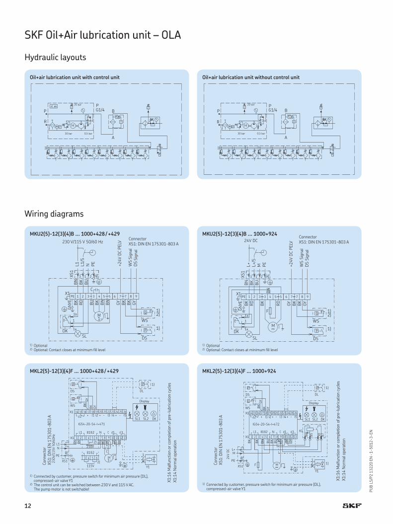
Hydraulic layouts
Oil+air lubrication unit with control unit Oil+air lubrication unit without control unit
MKU2(5)-12(3)(4)B ... 1000+428 / +429
Wiring diagrams
1) Optional2) Optional: Contact closes at minimum fill level
Connector
XS1: DIN EN 175301-803 A
Sig
nal
Sig
nal
1) Optional2) Optional: Contact closes at minimum fill level
Connector
XS1: DIN EN 175301-803 A
Sig
nal
Sig
nal
MKU2(5)-12(3)(4)B ... 1000+924
MKL2(5)-12(3)(4)F ... 1000+428 / +429
1) Connected by customer, pressure switch for minimum air pressure (DL), compressed-air valve Y1
2) The control unit can be switched between 230 V and 115 V AC. The pump motor is not switchable!
Connect
or
XS1: D
IN E
N 1
75301-803 A
X1:1
6 M
alfunct
ion o
r co
mple
tion o
f pre
-lu
bri
cation c
ycle
s
X1:1
4 N
orm
al opera
tion
Display
MKL2(5)-12(3)(4)F ... 1000+924
Connect
or
XS1: D
IN E
N 1
75301-803 A
1) Connected by customer, pressure switch for minimum air pressure (DL), compressed-air valve Y1
X1:1
6 M
alfunct
ion o
r co
mple
tion o
f pre
-lu
bri
cation c
ycle
s
X1:1
4 N
orm
al opera
tion
12
PU
B L
S/P
2 1
3220 E
N · 1
-5012-3-EN
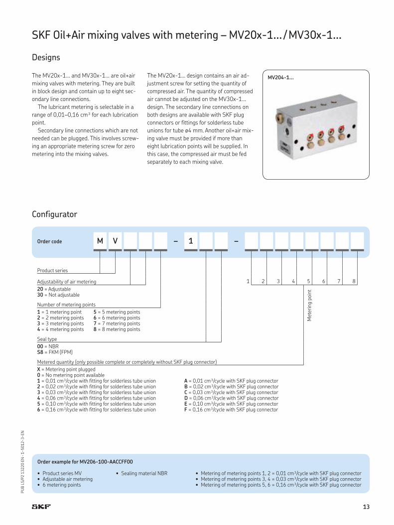
SKF Oil+Air mixing valves with metering – MV20x-1... / MV30x-1...
Designs
MV204-1...The MV20x-1... and MV30x-1... are oil+air
mixing valves with metering. They are built
in block design and contain up to eight sec-
ondary line connections.
The lubricant metering is selectable in a
range of 0,01–0,16 cm³ for each lubrication
point.
Secondary line connections which are not
needed can be plugged. This involves screw-
ing an appropriate metering screw for zero
metering into the mixing valves.
The MV20x-1... design contains an air ad-
justment screw for setting the quantity of
compressed air. The quantity of compressed
air cannot be adjusted on the MV30x-1...
design. The secondary line connections on
both designs are available with SKF plug
connectors or fittings for solderless tube
unions for tube ø4 mm. Another oil+air mix-
ing valve must be provided if more than
eight lubrication points will be supplied. In
this case, the compressed air must be fed
separately to each mixing valve.
Order example for MV206-100-AACCFF00
• Product series MV • Adjustable air metering• 6 metering points
• Sealing material NBR • Metering of metering points 1, 2 = 0,01 cm³/cycle with SKF plug connector• Metering of metering points 3, 4 = 0,03 cm³/cycle with SKF plug connector• Metering of metering points 5, 6 = 0,16 cm³/cycle with SKF plug connector
Order code M V – 1 –
2 3 4 5 6 7 8
Product series
1Adjustability of air metering
20 = Adjustable30 = Not adjustable
Number of metering points
1 = 1 metering point2 = 2 metering points3 = 3 metering points4 = 4 metering points
5 = 5 metering points6 = 6 metering points7 = 7 metering points8 = 8 metering points
Seal type
00 = NBRS8 = FKM (FPM)
Metered quantity (only possible complete or completely without SKF plug connector)
X = Metering point plugged0 = No metering point available1 = 0,01 cm³/cycle with fitting for solderless tube union2 = 0,02 cm³/cycle with fitting for solderless tube union3 = 0,03 cm³/cycle with fitting for solderless tube union4 = 0,06 cm³/cycle with fitting for solderless tube union5 = 0,10 cm³/cycle with fitting for solderless tube union6 = 0,16 cm³/cycle with fitting for solderless tube union
A = 0,01 cm³/cycle with SKF plug connectorB = 0,02 cm³/cycle with SKF plug connectorC = 0,03 cm³/cycle with SKF plug connectorD = 0,06 cm³/cycle with SKF plug connectorE = 0,10 cm³/cycle with SKF plug connectorF = 0,16 cm³/cycle with SKF plug connector
Configurator
Mete
ring p
oin
t
13
PU
B L
S/P
2 1
3220 E
N · 1
-5012-3-EN
SKF Oil+Air mixing valves with metering – MV20x-1... / MV30x-1...
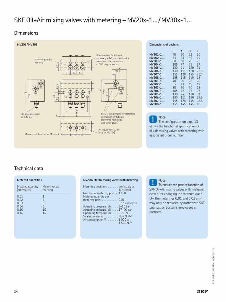
Dimensions
Metered quantity
marking
Oil+air outlets for tube ø4
optionally M8×1, counterbore for
solderless tube connection
or SKF plug connector
SKF plug connector
for tube ø4
Measurement connector M5, depth 9
Air adjustment screw
(only on MV20x)
M10×1 counterbore for solderless
connection for tube ø6
(delivered with plugs
and screw plugs)
MV203 / MV303
MV20x / MV30x mixing valves with metering
Mounting position . . . . . . . preferably as illustrated
Number of metering points . 1 to 8Metered quantity per metering point . . . . . . . . . . 0,01–
0,16 cm³/cycleActuating pressure, air . . . . 3–10 barActuating pressure, oil . . . . 17–40 barOperating temperature . . . . 5–80 °CSealing material . . . . . . . . NBR / FKM Air consumption 1) . . . . . . . 1 000 to
1 500 Nl/h
! Note
To ensure the proper function of
SKF Oil+Air mixing valves with metering
even after changing the metered quan-
tity, the meterings 0,01 and 0,02 cm³
may only be replaced by authorized SKF
Lubrication Systems employees or
partners.
Technical data
Metered quantities
Metered quantity[cm³/cycle]
Metering rate marking
0,01 10,02 20,03 30,06 60,10 100,16 16
! Note
The configurator on page 13
allows the functional specification of
oil+air mixing valves with metering with
associated order number.
Dimensions of designs
L A B CMV201-1... 40 20 22 20MV202-1... 55 43 45 19MV203-1... 80 60 70 23MV204-1... 105 77 95 27MV205-1... 130 94 120 31MV206-1... 130 111 120 22,5MV207-1... 155 128 145 26,5MV208-1... 155 145 145 18MV301-1... 40 20 22 20MV302-1... 55 43 45 19MV303-1... 80 60 70 23MV304-1... 105 77 95 27MV305-1... 130 94 120 31MV306-1... 130 111 120 22,5MV307-1... 155 128 145 26,5MV308-1... 155 145 145 18
14
PU
B L
S/P
2 1
3220 E
N · 1
-5012-3-EN
1) For secondary line with internal diameter of 2.3 mm and ISO VG 32 to 100 oil
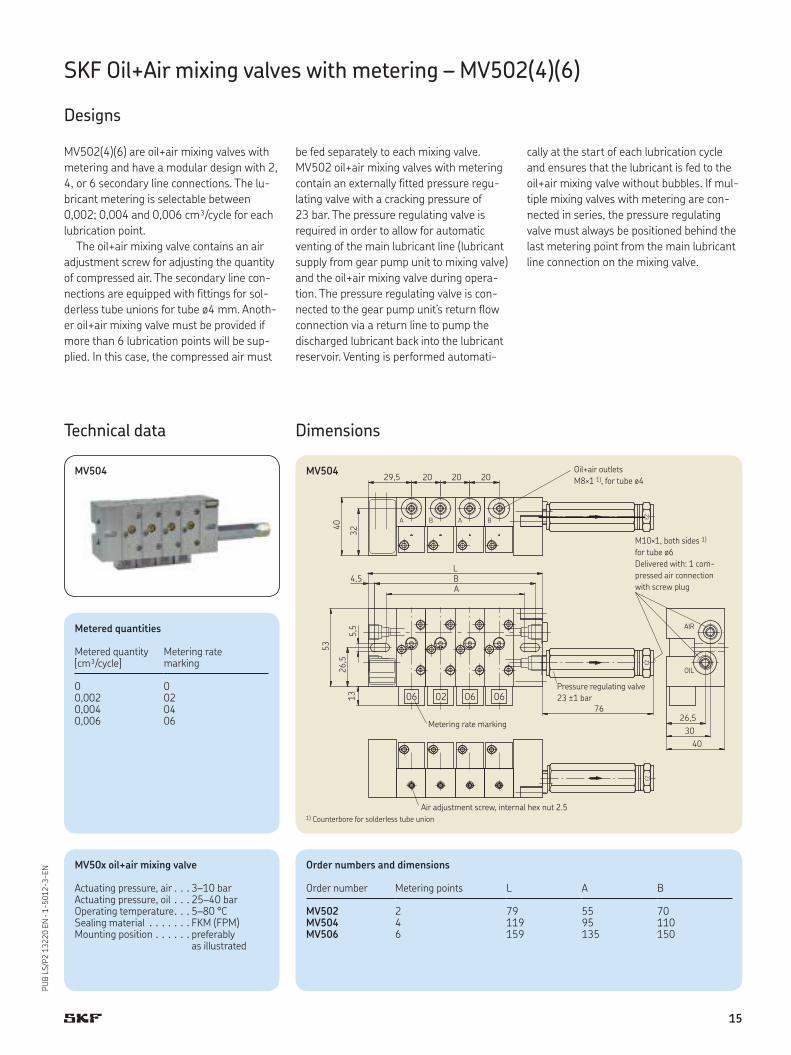
SKF Oil+Air mixing valves with metering – MV502(4)(6)
Designs
MV504
MV502(4)(6) are oil+air mixing valves with
metering and have a modular design with 2,
4, or 6 secondary line connections. The lu-
bricant metering is selectable between
0,002; 0,004 and 0,006 cm³/cycle for each
lubrication point.
The oil+air mixing valve contains an air
adjustment screw for adjusting the quantity
of compressed air. The secondary line con-
nections are equipped with fittings for sol-
derless tube unions for tube ø4 mm. Anoth-
er oil+air mixing valve must be provided if
more than 6 lubrication points will be sup-
plied. In this case, the compressed air must
be fed separately to each mixing valve.
MV502 oil+air mixing valves with metering
contain an externally fitted pressure regu-
lating valve with a cracking pressure of
23 bar. The pressure regulating valve is
required in order to allow for automatic
venting of the main lubricant line (lubricant
supply from gear pump unit to mixing valve)
and the oil+air mixing valve during opera-
tion. The pressure regulating valve is con-
nected to the gear pump unit’s return flow
connection via a return line to pump the
discharged lubricant back into the lubricant
reservoir. Venting is performed automati-
cally at the start of each lubrication cycle
and ensures that the lubricant is fed to the
oil+air mixing valve without bubbles. If mul-
tiple mixing valves with metering are con-
nected in series, the pressure regulating
valve must always be positioned behind the
last metering point from the main lubricant
line connection on the mixing valve.
Technical data
Metered quantities
Metered quantity[cm³/cycle]
Metering rate marking
0 00,002 020,004 040,006 06
MV50x oil+air mixing valve
Actuating pressure, air . . . 3–10 barActuating pressure, oil . . . 25–40 barOperating temperature . . . 5–80 °CSealing material . . . . . . . FKM (FPM) Mounting position . . . . . . preferably
as illustrated
Dimensions
MV504
Order numbers and dimensions
Order number Metering points L A B
MV502 2 79 55 70MV504 4 119 95 110MV506 6 159 135 150
Air adjustment screw, internal hex nut 2.5
Metering rate marking
Pressure regulating valve
23 ±1 bar
M10×1, both sides 1)
for tube ø6
Delivered with: 1 com-
pressed air connection
with screw plug
Oil+air outlets
M8×1 1), for tube ø4
1) Counterbore for solderless tube union
15
PU
B L
S/P
2 1
3220 E
N · 1
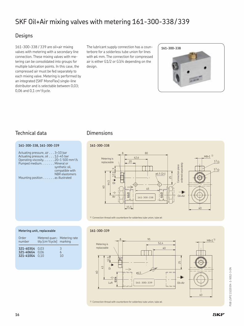
-5012-3-EN
161-300-338 / 339 are oil+air mixing
valves with metering with a secondary line
connection. These mixing valves with me-
tering can be consolidated into groups for
multiple lubrication points. In this case, the
compressed air must be fed separately to
each mixing valve. Metering is performed by
an integrated (SKF MonoFlex) single-line
distributor and is selectable between 0,03;
0,06 and 0,1 cm³/cycle.
The lubricant supply connection has a coun-
terbore for a solderless tube union for lines
with ø4 mm. The connection for compressed
air is either G1/2 or G3/4 depending on the
design.
SKF Oil+Air mixing valves with metering 161-300-338 / 339
Designs
161-300-338
Dimensions
161-300-338
161-300-339
Technical data
Metering unit, replaceable
Order number
Metered quan-tity [cm³/cycle]
Metering rate marking
321-403G4 0,03 3321-406G4 0,06 6321-410G4 0,10 10
Connect
ion p
iece
ord
ere
d s
epara
tely
Oil+Air
Oil
Air
Metering is
replaceable
1) Connection thread with counterbore for solderless tube union, tube ø4
1) Connection thread with counterbore for solderless tube union, tube ø4
Metering is
replaceable
Oil+Air
161-300-338, 161-300-339
Actuating pressure, air . . . 3–10 barActuating pressure, oil . . . 12–45 barOperating viscosity . . . . . . 20–1 500 mm²/sPumped medium . . . . . . . Mineral or
synthetic oil, compatible with NBR elastomers
Mounting position . . . . . . as illustrated
16
PU
B L
S/P
2 1
3220 E
N · 1
-5012-3-EN
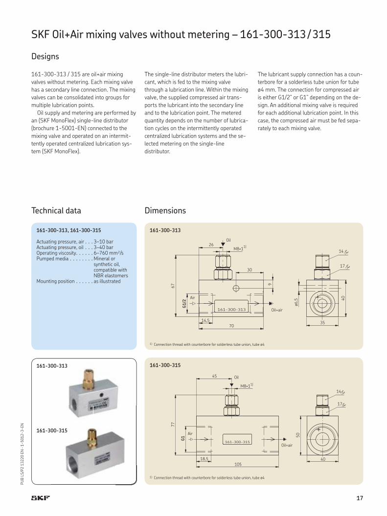
SKF Oil+Air mixing valves without metering – 161-300-313 / 315
Designs
161-300-313 / 315 are oil+air mixing
valves without metering. Each mixing valve
has a secondary line connection. The mixing
valves can be consolidated into groups for
multiple lubrication points.
Oil supply and metering are performed by
an (SKF MonoFlex) single-line distributor
(brochure 1-5001-EN) connected to the
mixing valve and operated on an intermit-
tently operated centralized lubrication sys-
tem (SKF MonoFlex).
The single-line distributor meters the lubri-
cant, which is fed to the mixing valve
through a lubrication line. Within the mixing
valve, the supplied compressed air trans-
ports the lubricant into the secondary line
and to the lubrication point. The metered
quantity depends on the number of lubrica-
tion cycles on the intermittently operated
centralized lubrication systems and the se-
lected metering on the single-line
distributor.
The lubricant supply connection has a coun-
terbore for a solderless tube union for tube
ø4 mm. The connection for compressed air
is either G1/2” or G1” depending on the de-
sign. An additional mixing valve is required
for each additional lubrication point. In this
case, the compressed air must be fed sepa-
rately to each mixing valve.
161-300-313
Dimensions
161-300-313
161-300-315
Technical data
1) Connection thread with counterbore for solderless tube union, tube ø4
1) Connection thread with counterbore for solderless tube union, tube ø4
Oil+air
Oil
Air
Oil+air
Oil
Air161-300-315
161-300-313, 161-300-315
Actuating pressure, air . . . 3–10 barActuating pressure, oil . . . 3–40 barOperating viscosity . . . . . . 6–760 mm²/sPumped media . . . . . . . . Mineral or
synthetic oil, compatible with NBR elastomers
Mounting position . . . . . . as illustrated
17
PU
B L
S/P
2 1
3220 E
N · 1
-5012-3-EN
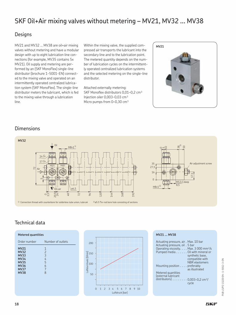
SKF Oil+Air mixing valves without metering – MV21, MV32 ... MV38
Designs
MV21MV21 and MV32 … MV38 are oil+air mixing
valves without metering and have a modular
design with up to eight lubrication line con-
nections (for example, MV35 contains 5x
MV21). Oil supply and metering are per-
formed by an (SKF MonoFlex) single-line
distributor (brochure 1-5001-EN) connect-
ed to the mixing valve and operated on an
intermittently operated centralized lubrica-
tion system (SKF MonoFlex). The single-line
distributor meters the lubricant, which is fed
to the mixing valve through a lubrication
line.
Within the mixing valve, the supplied com-
pressed air transports the lubricant into the
secondary line and to the lubrication point.
The metered quantity depends on the num-
ber of lubrication cycles on the intermittent-
ly operated centralized lubrication systems
and the selected metering on the single-line
distributor.
Attached externally metering:
SKF Monoflex distributors 0,01–0,2 cm³
Injection oiler 0,003-0,03 cm³
Micro pumps from 0–0,30 cm³
Dimensions
Technical data
Metered quantities
Order number Number of outlets
MV21 1MV32 2MV33 3MV34 4MV35 5MV36 6MV37 7MV38 8
MV32
1) Connection thread with counterbore for solderless tube union, tube ø4 2) ø5.5 Tie-rod bore hole consisting of sections
Oil+air
Oil
Air
deep
Air adjustment screw
MV21 ... MV38
Actuating pressure, air . Max. 10 barActuating pressure, oil . 5 barOperating viscosity . . . . Max. 3 000 mm²/sPumped media . . . . . . Oil with mineral or
synthetic base, compatible with NBR elastomers
Mounting position . . . . preferably as illustrated
Metered quantities (external lubricant distributors) . . . . . . . . 0,003–0,2 cm³/
cycle
18
PU
B L
S/P
2 1
3220 E
N · 1
-5012-3-EN
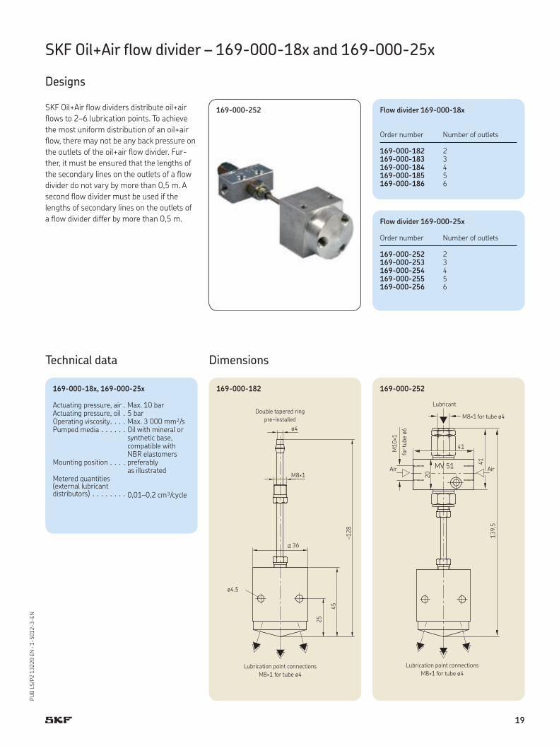
SKF Oil+Air flow divider – 169-000-18x and 169-000-25x
Designs
SKF Oil+Air flow dividers distribute oil+air
flows to 2–6 lubrication points. To achieve
the most uniform distribution of an oil+air
flow, there may not be any back pressure on
the outlets of the oil+air flow divider. Fur-
ther, it must be ensured that the lengths of
the secondary lines on the outlets of a flow
divider do not vary by more than 0,5 m. A
second flow divider must be used if the
lengths of secondary lines on the outlets of
a flow divider differ by more than 0,5 m.
Dimensions
169-000-182 169-000-252
Technical data
Flow divider 169-000-18x
Order number Number of outlets
169-000-182 2169-000-183 3169-000-184 4169-000-185 5169-000-186 6
169-000-252
Double tapered ring
pre-installed
Lubrication point connections
M8×1 for tube ø4
Air Air
Lubricant
for tube ø4
for
tube ø
6
Lubrication point connections
M8×1 for tube ø4
Flow divider 169-000-25x
Order number Number of outlets
169-000-252 2169-000-253 3169-000-254 4169-000-255 5169-000-256 6
169-000-18x, 169-000-25x
Actuating pressure, air . Max. 10 barActuating pressure, oil . 5 barOperating viscosity . . . . Max. 3 000 mm²/sPumped media . . . . . . Oil with mineral or
synthetic base, compatible with NBR elastomers
Mounting position . . . . preferably as illustrated
Metered quantities (external lubricant distributors) . . . . . . . . 0,01–0,2 cm³/cycle
19
PU
B L
S/P
2 1
3220 E
N · 1
-5012-3-EN
SKF Oil+Air lubrication
Accessories
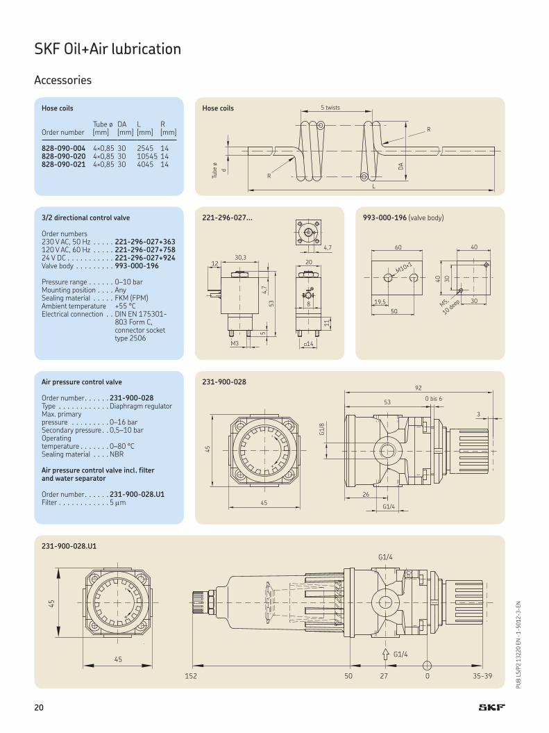
Hose coils
Tube ø
5 twistsHose coils
Order numberTube ø[mm]
DA[mm]
L[mm]
R[mm]
828-090-004 4×0,85 30 2545 14828-090-020 4×0,85 30 10545 14828-090-021 4×0,85 30 4045 14
Air pressure control valve
Order number . . . . . . 231-900-028Type . . . . . . . . . . . . Diaphragm regulatorMax. primary pressure . . . . . . . . . 0–16 barSecondary pressure . . 0,5–10 barOperating temperature . . . . . . . 0–80 °CSealing material . . . . NBR
Air pressure control valve incl. filter and water separator
Order number . . . . . . 231-900-028.U1Filter . . . . . . . . . . . . 5 m
231-900-028
231-900-028.U1
3/2 directional control valve
Order numbers230 V AC, 50 Hz . . . . . 221-296-027+363120 V AC, 60 Hz . . . . . 221-296-027+75824 V DC . . . . . . . . . . . 221-296-027+924Valve body . . . . . . . . . 993-000-196
Pressure range . . . . . . 0–10 barMounting position . . . . AnySealing material . . . . . FKM (FPM)Ambient temperature +55 °CElectrical connection . . DIN EN 175301-
803 Form C, connector socket type 2506
221-296-027... 993-000-196 (valve body)
10 dee
p
20
PU
B L
S/P
2 1
3220 E
N · 1
-5012-3-EN
SKF Oil+Air lubrication
Accessories
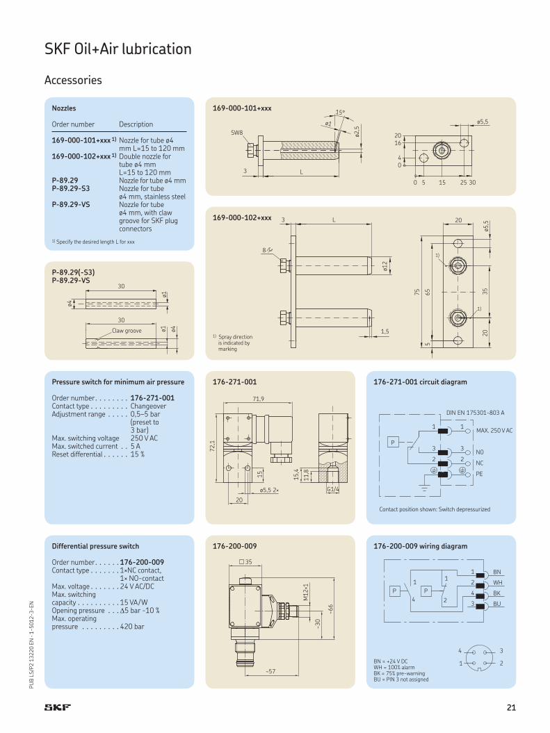
169-000-102+xxx
169-000-101+xxx
1) Spray direction is indicated by marking
Nozzles
Order number Description
169-000-101+xxx 1) Nozzle for tube ø4 mm L=15 to 120 mm
169-000-102+xxx 1) Double nozzle for tube ø4 mm L=15 to 120 mm
P-89.29 Nozzle for tube ø4 mmP-89.29-S3 Nozzle for tube
ø4 mm, stainless steelP-89.29-VS Nozzle for tube
ø4 mm, with claw groove for SKF plug connectors
1) Specify the desired length L for xxx
Differential pressure switch
Order number . . . . . . 176-200-009Contact type . . . . . . . 1×NC contact,
1× NO-contactMax. voltage . . . . . . . 24 V AC/DCMax. switchingcapacity . . . . . . . . . . 15 VA / WOpening pressure . . .5 bar -10 %Max. operating pressure . . . . . . . . . 420 bar
176-200-009 176-200-009 wiring diagram
BN = +24 V DCWH = 100% alarmBK = 75% pre-warningBU = PIN 3 not assigned
Claw groove
P-89.29(-S3) P-89.29-VS
Pressure switch for minimum air pressure
Order number . . . . . . . . 176-271-001Contact type . . . . . . . . . ChangeoverAdjustment range . . . . . 0,5–5 bar
(preset to 3 bar)
Max. switching voltage 250 V ACMax. switched current . . 5 AReset differential . . . . . . 15 %
176-271-001 176-271-001 circuit diagram
Contact position shown: Switch depressurized
MAX. 250 V AC
21
PU
B L
S/P
2 1
3220 E
N · 1
-5012-3-EN
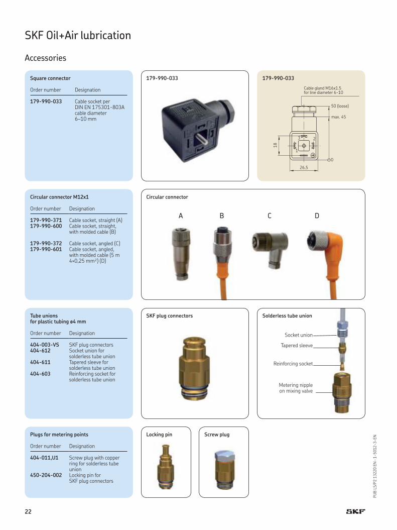
179-990-033
(loose)
Cable gland M16x1.5for line diameter 6-10
179-990-033
A B C D
Circular connector
Tapered sleeve
Reinforcing socket
Socket union
Metering nipple on mixing valve
Solderless tube union
Square connector
Order number Designation
179-990-033 Cable socket perDIN EN 175301-803Acable diameter 6–10 mm
Circular connector M12x1
Order number Designation
179-990-371 Cable socket, straight (A)179-990-600 Cable socket, straight,
with molded cable (B)
179-990-372 Cable socket, angled (C)179-990-601 Cable socket, angled,
with molded cable (5 m 4×0,25 mm²) (D)
Locking pin Screw plugPlugs for metering points
Order number Designation
404-011,U1 Screw plug with copper ring for solderless tube union
450-204-002 Locking pin for SKF plug connectors
Tube unionsfor plastic tubing ø4 mm
Order number Designation
404-003-VS SKF plug connectors404-612 Socket union for
solderless tube union404-611 Tapered sleeve for
solderless tube union404-603 Reinforcing socket for
solderless tube union
SKF Oil+Air lubrication
Accessories
SKF plug connectors
22
PU
B L
S/P
2 1
3220 E
N · 1
-5012-3-EN
SKF Oil+Air lubrication
Accessories
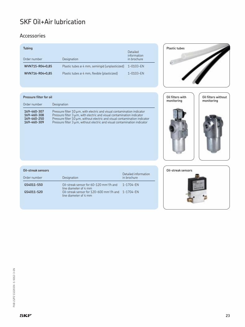
Tubing
Order number Designation
Detailed information in brochure
WVN715-R04×0,85 Plastic tubes ø 4 mm, semirigid (unplasticized) 1-0103-EN
WVN716-R04×0,85 Plastic tubes ø 4 mm, flexible (plasticized) 1-0103-EN
Pressure filter for oil
Order number Designation
169-460-307 Pressure filter 10 m, with electric and visual contamination indicator169-460-308 Pressure filter 3 m, with electric and visual contamination indicator169-460-250 Pressure filter 10 m, without electric and visual contamination indicator169-460-309 Pressure filter 3 m, without electric and visual contamination indicator
Oil-streak sensors
Order number DesignationDetailed information in brochure
GS4011-S50 Oil-streak sensor for 60-120 mm³/h and line diameter of 4 mm
1-1704-EN
GS4011-S20 Oil-streak sensor for 120-600 mm³/h and line diameter of 4 mm
1-1704-EN
Oil filters with monitoring
Oil filters without monitoring
Plastic tubes
Oil-streak sensors
23
PU
B L
S/P
2 1
3220 E
N · 1
-5012-3-EN
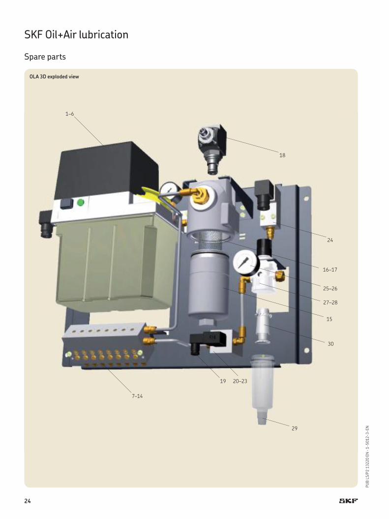
SKF Oil+Air lubrication
Spare parts
OLA 3D exploded view
1–6
7–14
15
16–17
18
19 20–23
24
25–26
27–28
30
29
24

PU
B L
S/P
2 1
3220 E
N · 1
-5012-3-EN
SKF Oil+Air lubrication
Spare parts
Spare parts list
Item Order number Designation
1 MKL2-12FC11000+428 Gear pump unit with IG54-20-S4-I control unit, for 230 V 50 / 60Hz2 MKL2-12FC11000+429 Gear pump unit with IG54-20-S4-I control unit, for 115 V 50 / 60Hz3 MKL2-12FC11000+924 Gear pump unit with IG54-20-S4-I control unit, for 24 V DC4 MKU2-12BC11000+428 Gear pump unit without control unit, for 230 V 50 / 60 Hz5 MKU2-12BC11000+429 Gear pump unit without control unit, for 115 V 50 / 60 Hz6 MKU2-12BC11000+924 Gear pump unit without control unit, for 24V DC
7 MV201-1… Oil+air metering unit, 1-port8 MV202-1… Oil+air metering unit, 2-port9 MV203-1… Oil+air metering unit, 3-port10 MV204-1… Oil+air metering unit, 4-port11 MV205-1… Oil+air metering unit, 5-port12 MV206-1… Oil+air metering unit, 6-port13 MV207-1… Oil+air metering unit, 7-port14 MV208-1… Oil+air metering unit, 8-port
15 853-880-011 NG40 housing for oil filters16 169-400-250 Filter element 10 m for oil filters17 169-400-260-V57 Filter element 3 m for oil filters18 176-200-009 Differential pressure switch for oil filters
19 179-990-465 Connector socket for 3 / 2 directional control valve20 221-296-027+263 3/2 directional control valve for 230 V, 50 Hz21 221-296-027+758 3/2 directional control valve for 120 V, 60 Hz22 221-296-027+924 3/2 directional control valve for 24 V DC23 993-000-196 Valve body, complete for 3 / 2 directional control valve
24 176-271-001 Pressure switch 3 bar for monitoring of minimum air pressure
25 169-101-606 Pressure gauge for air pressure reducing valve (sealing ring ordered separately = item 26)26 248-610.03 Sealing ring G1 / 8 CU for pressure gauge27 231-900-028.U1 Air pressure control valve + 5 μM filter complete with air filter and water separator28 231-900-028 Air pressure control valve without air filter and water separator29 231-900-035 Water separator container30 231-900-034 Filter insert 5 μM
31 995-810-047 Complete documentation for oil+air lubrication unit, incl. Declaration of Incorporation and Conformity
25
PU
B L
S/P
2 1
3220 E
N · 1
-5012-3-EN
Notes
26

PU
B L
S/P
2 1
3220 E
N · 1
-5012-3-EN
27
SKF Lubrication Systems Germany AG
Berlin Plant
Motzener Str. 35/37 · 12277 Berlin
PO Box 970444 · 12704 Berlin
Germany
Tel. +49 (0)30 72002-0
Fax +49 (0)30 72002-111
This brochure was presented to you by:
Bearings and unitsSeals Lubrication
systems
Mechatronics Services
The Power of Knowledge Engineering
Drawing on five areas of competence and application-specific expertise amassed over more than 100
years, SKF brings innovative solutions to OEMs and production facilities in every major industry world-
wide. These five competence areas include bearings and units, seals, lubrication systems, mechatronics
(combining mechanics and electronics into intelligent systems), and a wide range of services, from 3-D
computer modelling to advanced condition monitoring and reliability and asset management systems.
A global presence provides SKF customers uniform quality standards and worldwide product availability.
® SKF and SKF Oil+Air are registered trademarks of the SKF Group.
© SKF Group 2014
The contents of this publication are the copyright of the publisher and may not be reproduced (even extracts) unless prior written permis-
sion is granted. Every care has been taken to ensure the accuracy of the information contained in this publication. However, no liability can
be accepted for any loss or damage, whether direct, indirect or consequential, arising out of use of the information contained herein.
PUB LS/P2 13220 EN · June 2014 · 1-5012-3-EN
Further brochures:
1-0103-EN Fittings and Accessories
1-0994-EN Prevent Spindle Failures
1-1700-3-EN Control Units for Oil+Air Lubrication
1-1704-EN Flow Monitors and Sensors
1-2001-EN SKF MachineLube Lubrication Solutions for Machine Tools
1-5001-EN SKF MonoFlex Lubricant Distributors
1-5012-4-EN Injection Oilers, Micropumps
1-5012-EN Accessories for Minimal Quantity Metering
1-5102-EN SKF LubriLean – Minimal Quantity Lubrication
1-6917-EN Lubrication Solutions from SKF
1-9201-EN Transport of Lubricants in Centralized Lubrication Systems
! Important information on product usageAll products from SKF may be used only for their intended purpose as described in this
brochure and in any instructions. If operating instructions are supplied with the products, they must be read and followed.
Not all lubricants are suitable for use in centralized lubrication systems. SKF does offer an inspection service to test customer supplied lubricant to determine if it can be used in a central-ized system. SKF lubrication systems or their components are not approved for use with gases, liquefied gases, pressurized gases in solution and fluids with a vapor pressure exceeding normal atmospheric pressure (1 013 mbar) by more than 0,5 bar at their maximum permissible temperature.
Hazardous materials of any kind, especially the materials classified as hazardous by European Community Directive EC 67/548/EEC, Article 2, Par. 2, may only be used to fill SKF centralized lubrication systems and components and delivered and/or distributed with the same after consulting with and receiving written approval from SKF.
CAD models for products shown in
this brochure can be downloaded at:
skf-lubrication.partcommunity.com
skf.com/lubrication