
SKF Lubrication Planner · 2 SKF Lubrication Planner 1. Disclaimer ... hen this mode is selected...
24
SKF Lubrication Planner Instructions for use
Transcript of SKF Lubrication Planner · 2 SKF Lubrication Planner 1. Disclaimer ... hen this mode is selected...

SKF Lubrication Planner
Instructions for use
2 SKF Lubrication Planner
1. Disclaimer ........................................................................................................3
2. Installing the software .....................................................................................3
3. Starting the software .......................................................................................3
4. Task bar and features ......................................................................................44.1 Edit mode/Read only mode .......................................................................................... 44.2 Task lists .......................................................................................................................... 4 4.2.1 Create task lists based on strict date scheduling ............................................ 5 4.2.2 Create task lists based on “same day” date scheduling ................................. 8 4.2.3 Create task lists based on selection criteria ..................................................... 94.3 Labels ............................................................................................................................104.4 Search ...........................................................................................................................124.5 Settings .........................................................................................................................124.6 Database tools..............................................................................................................134.7 Useful links ...................................................................................................................144.8 What’s new ...................................................................................................................14
5. Data tree .......................................................................................................145.1 Home – Company Name ............................................................................................155.2 Factory ...........................................................................................................................165.3 Area ..............................................................................................................................165.4 Section ..........................................................................................................................165.5 Subsection ....................................................................................................................165.6 Machine .........................................................................................................................165.7 Part ..............................................................................................................................16
6. Tasks 176.1 LubeSelect input parameters .....................................................................................20
Table of contents
Original instructions
3SKF Lubrication Planner
1. Disclaimer
When installing the software, the user is accepting the conditions explained in the “Terms of use” displayed during the installation process. Read them carefully before accepting and proceed.
2. Installing the software
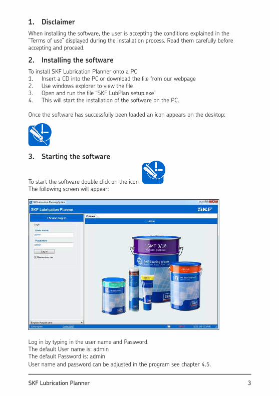
To install SKF Lubrication Planner onto a PC 1. Insert a CD into the PC or download the ile from our webpage2. Use windows explorer to view the ile3. Open and run the ile “SKF LubPlan setup.exe”4. This will start the installation of the software on the PC.
Once the software has successfully been loaded an icon appears on the desktop:
3. Starting the software
To start the software double click on the icon The following screen will appear:
Log in by typing in the user name and Password. The default User name is: adminThe default Password is: admin
User name and password can be adjusted in the program see chapter 4.5.
4 SKF Lubrication Planner
4. Task bar and features
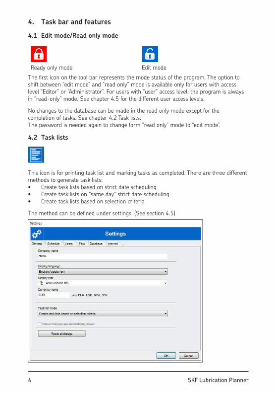
4.1 Edit mode/Read only mode
Ready only mode Edit mode
The irst icon on the tool bar represents the mode status of the program. The option to shift between “edit mode” and “read only” mode is available only for users with access level “Editor” or “Administrator”. For users with “user” access level, the program is always in “read-only” mode. See chapter 4.5 for the different user access levels.
No changes to the database can be made in the read only mode except for the completion of tasks. See chapter 4.2 Task lists. The password is needed again to change form “read only” mode to “edit mode”.
4.2 Task lists
This icon is for printing task list and marking tasks as completed. There are three different methods to generate task lists:• Create task lists based on strict date scheduling• Create task lists on “same day” strict date scheduling• Create task lists based on selection criteria
The method can be deined under settings. (See section 4.5)
5SKF Lubrication Planner
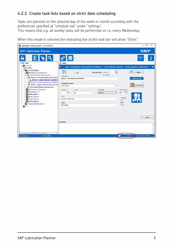
4.2.1 Create task lists based on strict date scheduling
Tasks are planned on the selected day of the week or month according with the preferences speciied at “schedule tab” under “settings”. This means that e.g. all weekly tasks will be performed on i.e. every Wednesday.
When this mode is selected the indicating box at the task bar will show “Strict”:
6 SKF Lubrication Planner
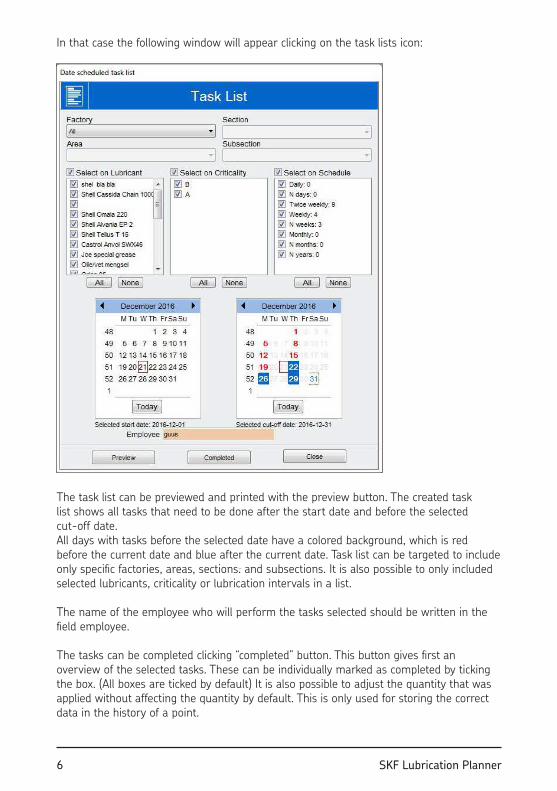
In that case the following window will appear clicking on the task lists icon:
The task list can be previewed and printed with the preview button. The created task list shows all tasks that need to be done after the start date and before the selected cut-off date. All days with tasks before the selected date have a colored background, which is red before the current date and blue after the current date. Task list can be targeted to include only speciic factories, areas, sections. and subsections. It is also possible to only included selected lubricants, criticality or lubrication intervals in a list.
The name of the employee who will perform the tasks selected should be written in the ield employee.
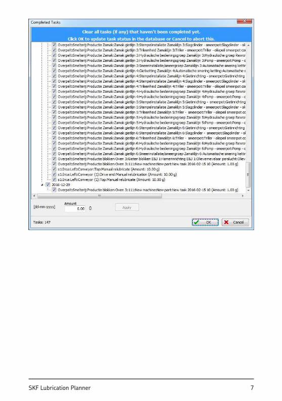
The tasks can be completed clicking “completed” button. This button gives irst an overview of the selected tasks. These can be individually marked as completed by ticking the box. (All boxes are ticked by default) It is also possible to adjust the quantity that was applied without affecting the quantity by default. This is only used for storing the correct data in the history of a point.
7SKF Lubrication Planner
8 SKF Lubrication Planner
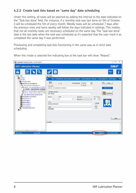
4.2.2 Create task lists based on “same day” date scheduling
Under this setting, all tasks will be planned by adding the interval to the date indicated on the “Task last done” ield. For instance, if a monthly task was last done on 5th of October, it will be scheduled the 5th of every month. Weekly tasks will be scheduled 7 days after the previous ones and twice weekly will follow the days indicated in settings. This implies that not all monthly tasks are necessary scheduled on the same day. The “task last done” date is the last date when the task was scheduled as it’s expected that the user mark it as completed the same day it was performed.
Previewing and completing task lists functioning in the same way as in strict date scheduling.
When this mode is selected the indicating box at the task bar will show “Repeat”:
9SKF Lubrication Planner
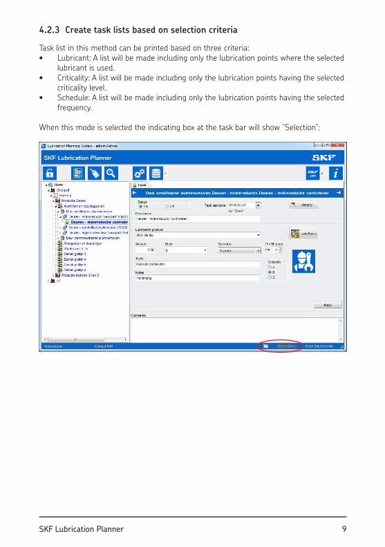
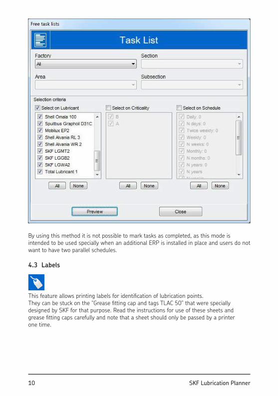
4.2.3 Create task lists based on selection criteria
Task list in this method can be printed based on three criteria: • Lubricant: A list will be made including only the lubrication points where the selected
lubricant is used.• Criticality: A list will be made including only the lubrication points having the selected
criticality level.• Schedule: A list will be made including only the lubrication points having the selected
frequency.
When this mode is selected the indicating box at the task bar will show “Selection”:
10 SKF Lubrication Planner
By using this method it is not possible to mark tasks as completed, as this mode is intended to be used specially when an additional ERP is installed in place and users do not want to have two parallel schedules.
4.3 Labels
This feature allows printing labels for identiication of lubrication points.They can be stuck on the “Grease itting cap and tags TLAC 50” that were specially designed by SKF for that purpose. Read the instructions for use of these sheets and grease itting caps carefully and note that a sheet should only be passed by a printer one time.
11SKF Lubrication Planner
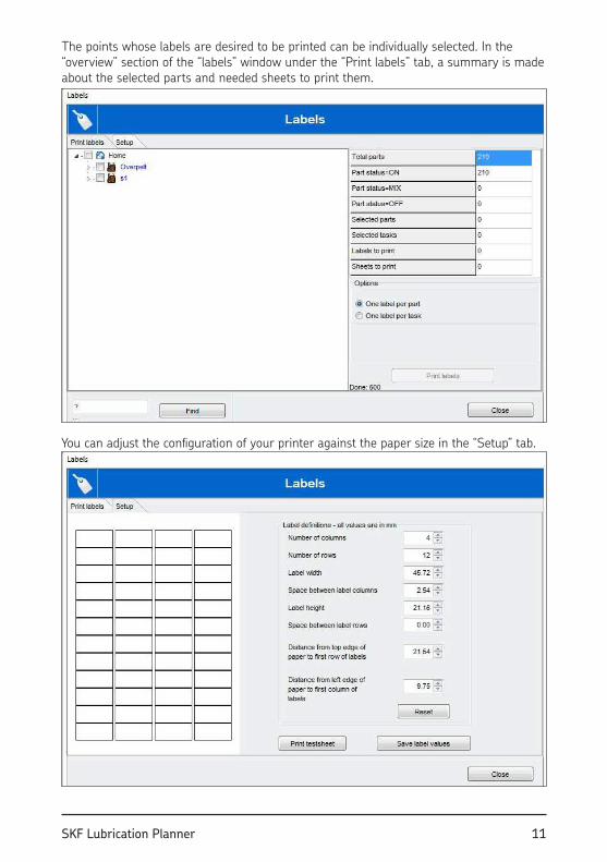
The points whose labels are desired to be printed can be individually selected. In the “overview” section of the “labels” window under the “Print labels” tab, a summary is made about the selected parts and needed sheets to print them.
You can adjust the coniguration of your printer against the paper size in the “Setup” tab.
12 SKF Lubrication Planner
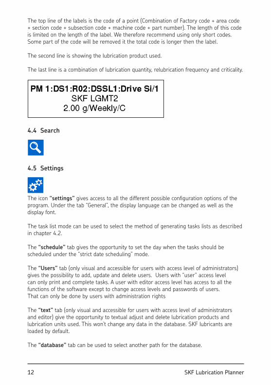
The top line of the labels is the code of a point (Combination of Factory code + area code + section code + subsection code + machine code + part number). The length of this code is limited on the length of the label. We therefore recommend using only short codes. Some part of the code will be removed it the total code is longer then the label.
The second line is showing the lubrication product used.
The last line is a combination of lubrication quantity, relubrication frequency and criticality.
4.4 Search
4.5 Settings
The icon “settings” gives access to all the different possible coniguration options of the program. Under the tab “General”, the display language can be changed as well as the display font.
The task list mode can be used to select the method of generating tasks lists as described in chapter 4.2.
The “schedule” tab gives the opportunity to set the day when the tasks should be scheduled under the “strict date scheduling” mode.
The “Users” tab (only visual and accessible for users with access level of administrators) gives the possibility to add, update and delete users. Users with “user” access level can only print and complete tasks. A user with editor access level has access to all the functions of the software except to change access levels and passwords of users. That can only be done by users with administration rights
The “text” tab (only visual and accessible for users with access level of administrators and editor) give the opportunity to textual adjust and delete lubrication products and lubrication units used. This won’t change any data in the database. SKF lubricants are loaded by default.
The “database” tab can be used to select another path for the database.
13SKF Lubrication Planner
4.6 Database tools
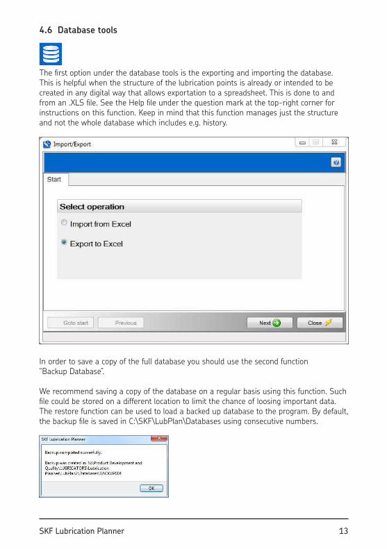
The irst option under the database tools is the exporting and importing the database. This is helpful when the structure of the lubrication points is already or intended to be created in any digital way that allows exportation to a spreadsheet. This is done to and from an .XLS ile. See the Help ile under the question mark at the top-right corner for instructions on this function. Keep in mind that this function manages just the structure and not the whole database which includes e.g. history.
In order to save a copy of the full database you should use the second function “Backup Database”.
We recommend saving a copy of the database on a regular basis using this function. Such ile could be stored on a different location to limit the chance of loosing important data. The restore function can be used to load a backed up database to the program. By default, the backup ile is saved in C:\SKF\LubPlan\Databases using consecutive numbers.
14 SKF Lubrication Planner
The “upload database” function will sent the database to an SKF server. The data provided could be processed for marketing, sales and product development purposes.
The “email database” function can be used to send an email including the database.
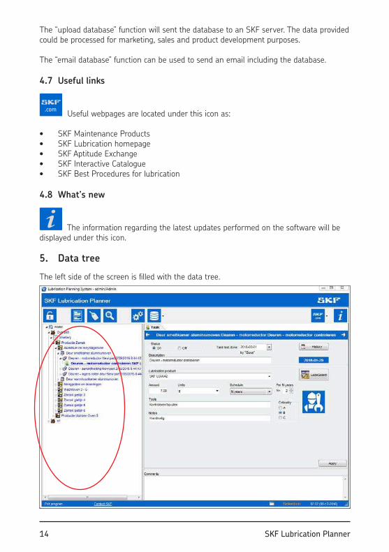
4.7 Useful links
Useful webpages are located under this icon as:
• SKF Maintenance Products • SKF Lubrication homepage• SKF Aptitude Exchange • SKF Interactive Catalogue• SKF Best Procedures for lubrication
4.8 What’s new
The information regarding the latest updates performed on the software will be displayed under this icon.
5. Data tree
The left side of the screen is illed with the data tree.
15SKF Lubrication Planner
Basically, the tree represents the structure of a facility. It uses 5 levels over the tasks:
Company Name>Factories>Areas>Sections>Subsections>Machines>Parts>Tasks
New data can be created through importing data as explained in chapter 4.6, or directly on this tree by adding new parts, or copying them.
The order in the data tree determines the sequence of tasks when printing a list. The structure can be modiied by “dragging and dropping”.
When a node is selected, the information regarding that node is displayed in the right part of the window.
The color of a node in the tree is representing the status of the node. Nodes that are “on” are blue. All tasks under this node will be scheduled in the task lists. Nodes that are “off” are represented in grey. These aren’t scheduled in the task lists and are useful when a part of the plant is temporarily shut down. Nodes that have mixed “on” and “off” tasks underneath them are represented as black.
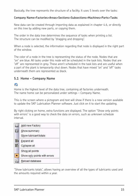
5.1 Home – Company Name
Home is the highest level of the data tree, containing all factories underneath. The name home can be personalized under settings – Company Name.
This is the screen where a pictogram and text will show if there is a new version available to update the SKF Lubrication Planner software. Just click on it to start the updating.
By right clicking on home, extra functions are displayed. The option “Show only points with errors” is a good way to check the data on errors, such as unknown schedule interval.
“Show lubricants totals”, allows having an overview of all the types of lubricants used and the amounts required within a year.
16 SKF Lubrication Planner
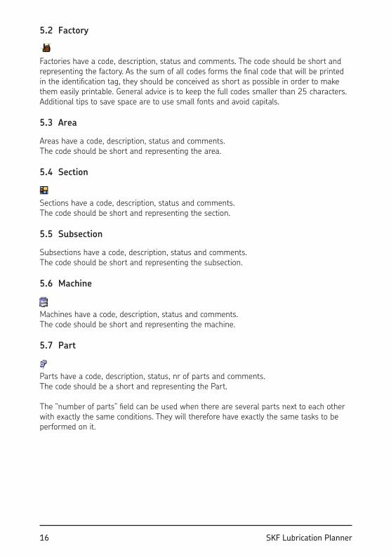
5.2 Factory
Factories have a code, description, status and comments. The code should be short and representing the factory. As the sum of all codes forms the inal code that will be printed in the identiication tag, they should be conceived as short as possible in order to make them easily printable. General advice is to keep the full codes smaller than 25 characters. Additional tips to save space are to use small fonts and avoid capitals.
5.3 Area
Areas have a code, description, status and comments.The code should be short and representing the area.
5.4 Section
Sections have a code, description, status and comments. The code should be short and representing the section.
5.5 Subsection
Subsections have a code, description, status and comments.The code should be short and representing the subsection.
5.6 Machine
Machines have a code, description, status and comments. The code should be short and representing the machine.
5.7 Part
Parts have a code, description, status, nr of parts and comments. The code should be a short and representing the Part.
The “number of parts” ield can be used when there are several parts next to each other with exactly the same conditions. They will therefore have exactly the same tasks to be performed on it.
17SKF Lubrication Planner
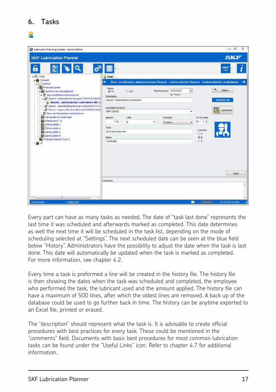
6. Tasks
Every part can have as many tasks as needed. The date of “task last done” represents the last time it was scheduled and afterwards marked as completed. This date determines as well the next time it will be scheduled in the task list, depending on the mode of scheduling selected at “Settings”. The next scheduled date can be seen at the blue ield below “History”. Administrators have the possibility to adjust the date when the task is last done. This date will automatically be updated when the task is marked as completed. For more information, see chapter 4.2.
Every time a task is preformed a line will be created in the history ile. The history ile is then showing the dates when the task was scheduled and completed, the employee who performed the task, the lubricant used and the amount applied. The history ile can have a maximum of 500 lines, after which the oldest lines are removed. A back up of the database could be used to go further back in time. The history can be anytime exported to an Excel ile, printed or erased.
The “description” should represent what the task is. It is advisable to create oficial procedures with best practices for every task. These could be mentioned in the “comments” ield. Documents with basic best procedures for most common lubrication tasks can be found under the “Useful Links” icon. Refer to chapter 4.7 for additional information.
18 SKF Lubrication Planner
Lubrication product, amount, unit and schedule should be illed in at every task.
“Tools” and “Notes” can be illed in as extra info that is printed on the task list. This is good to make sure that the lubrication technician is carrying with him all required things to properly perform the task, as grease guns, cleaners, automatic lubricators, ittings, ilters, etc.
Criticality can be speciied here to address the importance of the task. This is also printed on the task list.
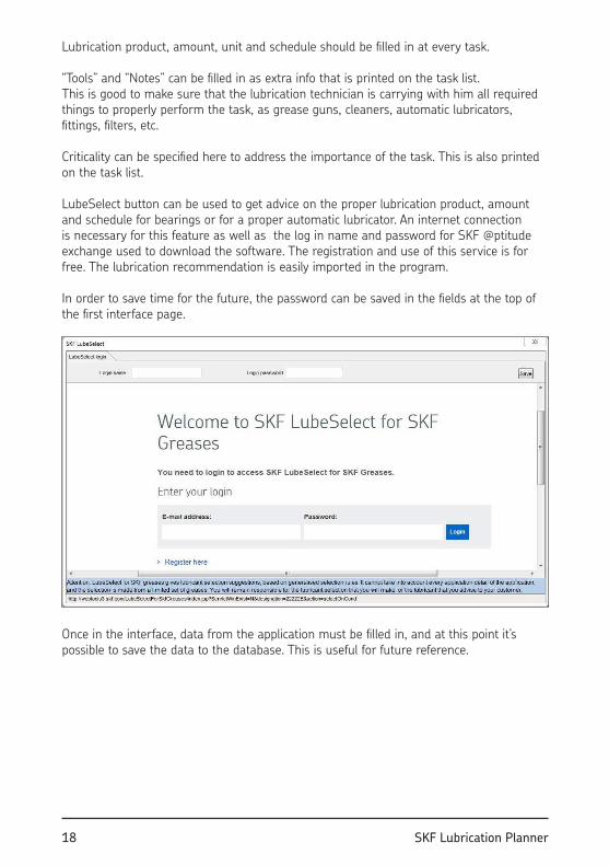
LubeSelect button can be used to get advice on the proper lubrication product, amount and schedule for bearings or for a proper automatic lubricator. An internet connection is necessary for this feature as well as the log in name and password for SKF @ptitude exchange used to download the software. The registration and use of this service is for free. The lubrication recommendation is easily imported in the program.
In order to save time for the future, the password can be saved in the ields at the top of the irst interface page.
Once in the interface, data from the application must be illed in, and at this point it’s possible to save the data to the database. This is useful for future reference.
19SKF Lubrication Planner
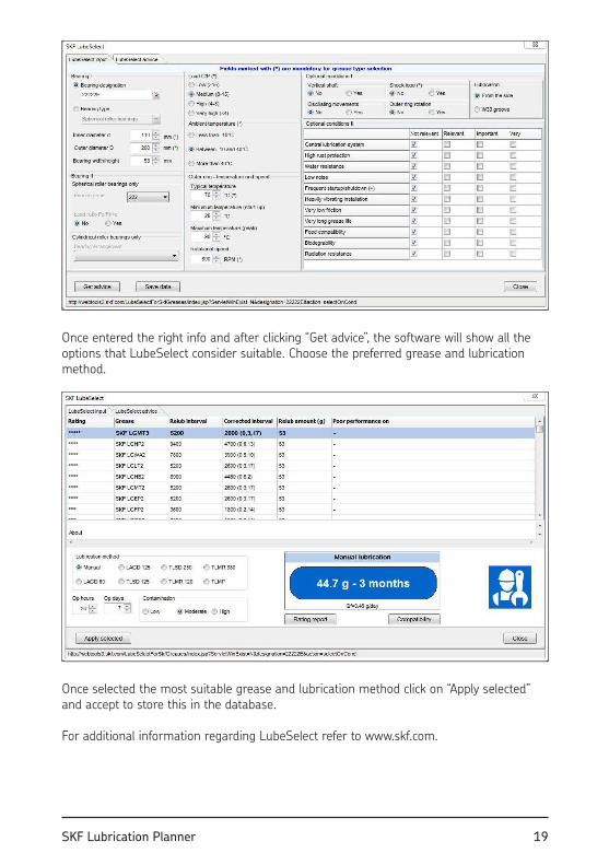
Once entered the right info and after clicking “Get advice”, the software will show all the options that LubeSelect consider suitable. Choose the preferred grease and lubrication method.
Once selected the most suitable grease and lubrication method click on “Apply selected” and accept to store this in the database.
For additional information regarding LubeSelect refer to www.skf.com.
20 SKF Lubrication Planner
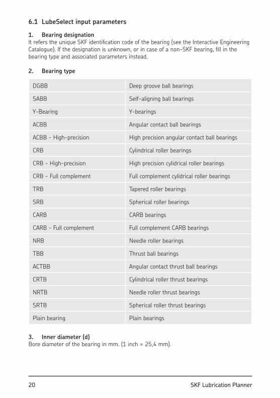
6.1 LubeSelect input parameters
1. Bearing designationIt refers the unique SKF identiication code of the bearing (see the Interactive Engineering Catalogue). If the designation is unknown, or in case of a non-SKF bearing, ill in the bearing type and associated parameters instead.
2. Bearing type
DGBB Deep groove ball bearings
SABB Self-aligning ball bearings
Y-Bearing Y-bearings
ACBB Angular contact ball bearings
ACBB - High-precision High precision angular contact ball bearings
CRB Cylindrical roller bearings
CRB - High-precision High precision cylidrical roller bearings
CRB - Full complement Full complement cylidrical roller bearings
TRB Tapered roller bearings
SRB Spherical roller bearings
CARB CARB bearings
CARB - Full complement Full complement CARB bearings
NRB Needle roller bearings
TBB Thrust ball bearings
ACTBB Angular contact thrust ball bearings
CRTB Cylindrical roller thrust bearings
NRTB Needle roller thrust bearings
SRTB Spherical roller thrust bearings
Plain bearing Plain bearings
3. Inner diameter (d)Bore diameter of the bearing in mm. (1 inch = 25,4 mm).
21SKF Lubrication Planner
4. Outer diameter (D)Outside diameter of the bearing in mm. (1 inch = 25,4 mm).
5. Bearing width/height (B,H)Height is used for radial bearings, Width for thrust bearings. This value is displayed on the results screen.
6. Filling typeLubeSelect for SKF greases concerns SKF greases only.
7. Load (C/P)Ratio of the basic dynamic load rating (C) divided by the equivalent dynamic bearing lead (P). This parameter is used to assess lubricants load capacity (antiwear properties EP, etc.) (See the General Catalog or IEC for calculation of the load).
8. Typical temperature (outer ring)Temperature in degrees Celsius of the bearing measured on the outer ring during normal operation in the application. Conversion: temperature in degrees Celsius= (5/9)*(temperature in degrees Fahrenheit-32).
9. Minimum temperature (start-up)It stands for the minimum temperature of the bearing at start-up in the application.Conversion: temperature in degrees Celsius= (5/9)*(temperature in degrees Fahrenheit-32).
10. Maximum temperature (peak)This is the peak temperature of the bearing in the application. Meaning the maximum temperature which can occur during operation or standing still.Conversion: temperature in degrees Celsius= (5/9)*(temperature in degrees Fahrenheit-32).
11. Rotational speedBearing speed, in number of revolutions per minute (RPM).
12. Shock loadBearings subjected to short, impulse-like loads, like railway boogie bearings or wind peaks acting on wind turbines and its gearbox bearings.
13. Ambient temperatureRefers to the Air temperature in the direct surroundings of the bearing (e.g. oven temperature). This parameter is used to prefer lower/higher grease consistency.
14. Bearing ArrangementThe arrangement the bearing is applied in. Used for calculating speed limits for CRB bearing.

22 SKF Lubrication Planner
15. SRB SeriesFirst three digits of SRB bearing designation, indicating which series the SRB belongs. Used for calculating speed limit for SRB bearing.
16. Large axial loadThis corresponds to the ratio of axial force and radial force larger than calculation factor e in the SKF General Catalogue 6000. Used for calculating speed limit for SRB bearing.
17. Vertical shaftSelect it where the application considers shaft in vertical position. This parameter is used to prefer leakage resistance properties.
18. Oscillating movementsBearing which does not revolve but swings back and forth. This parameter is used to prefer good anti-brinelling performance, or greases which easily provide lubricant into the contact.
19. Outer ring rotationApplicable when the outer ring is rotating instead of the inner ring. This parameter is used to prefer greases which are mechanically stable and can withstand high G-forces. (GAST test).
20. High rust protection requiredThis is important in case of aggressive water contamination (with possible additives). Typical examples: pulp & paper application, metal working, and many others.
21. Water resistance requiredThis is important in case of a highly humid environment or water spraying onto the bearing. Typical examples: water cooled bearings (as in the steel industry), bearings on the bottom of a car (because of the pools on the roads).
22. Low noise required‘Low noise’ is interpreted as a noise level of QE4 or QE5 for bearings with an outer diameter smaller than 47 mm, and a noise level of QE5 or QE6 for bearings with an outer diameter larger than 47 mm.
23. Frequent start-up/shutdownFrequent means more than once per day in this context. With this parameter, lubricants are preferred with good antiwear properties and high viscosity. Typical example: a car, stopping and accelerating frequently in city trafic.
24. Heavily vibrating installationWhen high G-forces (G>1) are present. Typical examples: railway axle boxes, vibrating screens. With this parameter, greases are preferred with good mechanical stability, tested in V2F test.
23SKF Lubrication Planner
25. Very low friction requiredRelevant in applications where a low start-up or running torque is required, or if a low running temperature is wanted. This parameter is used to prefer low base-oil viscosity. Typical example: textile industry, spindles, robots.
26. Very long grease life requiredIt’s Relevant in certain sealed/shielded bearing applications, especially when they are running at high temperatures. Typical example: car alternators, high speed electrical motors (in this case bearing life depends upon grease life).
27. Food compatibility requiredImportant if there is any chance at all that the grease will come into contact with food or food wrappings.
28. Biodegradability requiredThis is very important in case of signiicant total-loss of lubricant, or when legal requirements are in place. Typical examples: farming and forestry.
29. Radiation presentIt refers to the presence of radiation. Grease must not degrade as a result of radiation. Preference is given to radiation resistant greases. Typical example: nuclear radiation.
30. Central lubrication systemWhen this parameter is selected, greases with good pumpability are preferred.
31. W33 Groove It must be selected when the replenishment is made through the bearing outer or inner ring, instead of from the side. This parameter is used to calculate the required relubrication quantity.
32. Contamination This parameter is used to adjust the relubrication interval.

skf.com | mapro.skf.com | skf.com/lubrication
® SKF is a registered trademark of the SKF Group.
© SKF Group 2017The contents of this publication are the copyright of the publisher and may not be reproduced (even extracts) unless prior written permission is granted. Every care has been taken to ensure the accuracy of the information contained in this publication but no liability can be accepted for any loss or damage whether direct, indirect or consequential arising out of the use of the information contained herein.
MP5367 EN · 2017/01