SKA PHASE 1 SYSTEM REQUIREMENTS SPECIFICATION
58
Name Designation Affiliation Date Signature Submitted by: T. Stevenson System Engineer SPDO 2011‐02‐14 J.G. Bij de Vaate, A.J. Boonstra, A. Gunst, R. Nijboer, A.J. Faulkner and P. Alexander. Approved for release as part of SKA System dCoDR documents: P. Dewdney Project Engineer SPDO 2011‐02‐14 Important This is a living document and is intended to be filled, extended and augmented as the Requirements Capture activity continues. It will receive its first formal release prior to SKA Phase 1 System Requirements Review. SKA PHASE 1 SYSTEM REQUIREMENTS SPECIFICATION Document number ................................................................. WP2‐005.030.000‐SRS‐002 Revision ........................................................................................................................... B Author ............................................................................... T. Stevenson et al (see below) Date ................................................................................................................. 2011‐02‐14 Status ........................ First Draft – Comments, omissions and contradictions unresolved
Transcript of SKA PHASE 1 SYSTEM REQUIREMENTS SPECIFICATION

Name Designation Affiliation Date Signature
Submitted by:
T. Stevenson System Engineer SPDO 2011‐02‐14
J.G. Bij de Vaate, A.J. Boonstra, A. Gunst, R. Nijboer, A.J. Faulkner and P. Alexander.
Approved for release as part of SKA System dCoDR documents:
P. Dewdney Project Engineer SPDO 2011‐02‐14
Important
This is a living document and is intended to be filled, extended and augmented as the
Requirements Capture activity continues. It will receive its first formal release prior to
SKA Phase 1 System Requirements Review.
SKA PHASE 1 SYSTEM REQUIREMENTS SPECIFICATION
Document number ................................................................. WP2‐005.030.000‐SRS‐002
Revision ........................................................................................................................... B
Author ............................................................................... T. Stevenson et al (see below)
Date ................................................................................................................. 2011‐02‐14
Status ........................ First Draft – Comments, omissions and contradictions unresolved

WP2‐005.030.000‐SRS‐002 Revision : B
2011‐02‐14 Page 2 of 58
DOCUMENT HISTORY
Revision Date Of Issue Engineering Change
Number
Comments
A 2011‐02‐07 ‐ First draft release for internal review
B 2011‐02‐14 ‐ Updated following review
DOCUMENT SOFTWARE
Package Version Filename
Wordprocessor MSWord Word 2007 WP2‐005.030.000‐SRS‐002‐B_SKA1SysReqSpec
ORGANISATION DETAILS
Name SKA Program Development Office
Physical/Postal
Address
Jodrell Bank Centre for Astrophysics
Alan Turing Building
The University of Manchester
Oxford Road
Manchester, UK
M13 9PL
Fax. +44 (0)161 275 4049
Website www.skatelescope.org

WP2‐005.030.000‐SRS‐002 Revision : B
2011‐02‐14 Page 3 of 58
TABLE OF CONTENTS
1 INTRODUCTION ............................................................................................. 7
1.1 Purpose and scope of the document ...................................................................................... 7
1.2 Notes on document format..................................................................................................... 7
2 REFERENCES ................................................................................................. 8
2.1 Applicable documents ............................................................................................................. 8
2.2 Reference documents ............................................................................................................. 8
3 FUNCTIONAL AND PERFORMANCE REQUIREMENTS ................................................. 9
3.1 Functional Overview ............................................................................................................... 9
3.2 Science Requirements Derivation ......................................................................................... 11
3.3 Spectral Characteristics ......................................................................................................... 13
3.3.1 Operating Frequency ..................................................................................................... 13
3.3.2 Instantaneous Bandwidth ............................................................................................. 13
3.3.3 Number, width and placement of station output bands .............................................. 14
3.3.4 Spectral flatness ............................................................................................................ 14
3.3.5 Spectral Resolution ....................................................................................................... 15
3.3.6 Spectral Dynamic Range ................................................................................................ 16
3.4 SKA1 Sensitivity and Survey requirements ............................................................................ 16
3.4.1 Sensitivity ...................................................................................................................... 16
3.4.2 Survey speed ................................................................................................................. 16
3.4.3 Survey ‘On‐Sky’ time ..................................................................................................... 17
3.4.4 Deep Field Integration Time .......................................................................................... 17
3.5 Baseline requirements .......................................................................................................... 17
3.6 Temporal characteristics ....................................................................................................... 18
3.6.1 Main beam stability ....................................................................................................... 18
3.6.2 Temporal resolution ...................................................................................................... 18
3.6.3 Spatial side‐lobe stability .............................................................................................. 18
3.6.4 Beam‐switching agility .................................................................................................. 18
3.6.5 Frequency switching agility ........................................................................................... 19
3.7 Polarisation characteristics ................................................................................................... 19
3.8 RFI avoidance ........................................................................................................................ 20
3.9 Imaging characteristics .......................................................................................................... 20
3.9.1 Instantaneous field of view ........................................................................................... 20
3.9.2 Imaging dynamic range ................................................................................................. 20
3.9.3 Pointing accuracy .......................................................................................................... 21
3.9.4 Pointing estimation accuracy ........................................................................................ 21
3.10 Monitoring and Control (M&C) Function .............................................................................. 21
3.10.1 Top‐level requirements ................................................................................................. 21
3.10.2 Control requirements .................................................................................................... 24
3.10.3 Monitoring requirements .............................................................................................. 25
3.11 Data Acquisition Characteristics ........................................................................................... 26
WP2‐005.030.000‐SRS‐002 Revision : B
2011‐02‐14 Page 4 of 58
3.12 Observational Modes ............................................................................................................ 26
3.12.1 Top level modes ............................................................................................................ 26
3.12.2 Data Products ................................................................................................................ 27
4 OPERATIONAL REQUIREMENTS ....................................................................... 28
4.1 General .................................................................................................................................. 28
4.2 Routine operations ................................................................................................................ 28
4.3 Start‐up and shutdown ......................................................................................................... 29
4.4 Failure management ............................................................................................................. 31
4.4.1 General .......................................................................................................................... 31
4.4.2 Detection and reporting ................................................................................................ 32
4.4.3 Diagnosis and recovery ................................................................................................. 33
4.4.4 Lifetime ......................................................................................................................... 34
4.5 Maintenance ......................................................................................................................... 35
4.6 Disposal phase ....................................................................................................................... 38
5 DESIGN CONSTRAINTS .................................................................................. 38
5.1 Environmental Requirements ............................................................................................... 38
5.1.1 General .......................................................................................................................... 38
5.1.2 Site and infrastructure requirements ........................................................................... 39
5.1.3 Contamination and precipitation .................................................................................. 39
5.1.4 Climatic requirements ................................................................................................... 40
5.1.5 Radio Frequency Interference ....................................................................................... 41
5.1.6 Electro Magnetic Compatibility ..................................................................................... 41
5.1.7 Self‐generated RFI environment ................................................................................... 43
5.1.8 Lightning ........................................................................................................................ 43
5.1.9 Grounding...................................................................................................................... 43
5.1.10 Corrosion ....................................................................................................................... 44
5.1.11 Seismicity ....................................................................................................................... 44
5.1.12 Other Aspects ................................................................................................................ 44
5.2 Engineering Design Constraints ............................................................................................ 45
5.2.1 General .......................................................................................................................... 45
5.2.2 Size and weight ............................................................................................................. 46
5.2.3 Materials and Processes ................................................................................................ 46
5.2.4 Marking ......................................................................................................................... 47
5.2.5 Power and other utilities ............................................................................................... 48
5.3 Quality Factors Requirements ............................................................................................... 48
5.3.1 General .......................................................................................................................... 48
5.3.2 Workmanship ................................................................................................................ 49
5.3.3 System Safety ................................................................................................................ 49
5.3.4 Security .......................................................................................................................... 50
5.3.5 Reliability ....................................................................................................................... 50
5.3.6 Maintainability .............................................................................................................. 50
5.3.7 Flexibility and upgradability .......................................................................................... 51
5.3.8 Accessibility and testability ........................................................................................... 51

WP2‐005.030.000‐SRS‐002 Revision : B
2011‐02‐14 Page 5 of 58
5.3.9 Transportability and storage ......................................................................................... 52
5.3.10 Life ................................................................................................................................. 53
6 INTERFACE REQUIREMENTS ............................................................................ 53
6.1 External Interfaces ................................................................................................................ 53
6.1.1 Power ............................................................................................................................ 53
6.1.2 Data synchronization..................................................................................................... 54
6.2 Internal Interfaces ................................................................................................................. 54
6.2.1 Power ............................................................................................................................ 54
6.3 Synchronization ..................................................................................................................... 55
7 SUPPORT REQUIREMENTS ............................................................................. 55
7.1 Maintenance ......................................................................................................................... 55
7.2 Logistics ................................................................................................................................. 55
8 EXTENSIBILITY REQUIREMENTS ....................................................................... 55
8.1 Extension interfaces .............................................................................................................. 56
8.2 Extension performance ......................................................................................................... 56
9 QUALITY ASSURANCE PROVISIONS................................................................... 57
9.1 System Qualification testing ................................................................................................. 57
9.2 Test Methods ........................................................................................................................ 57
APPENDIX 1. LIST OF DRM TECHNICAL SPECIFICATIONS .............................................. 58
LIST OF FIGURES
Figure 1: High level SKA functional context diagram .............................................................................. 9
Figure 2: 2nd layer of the SKA functional hierarchy ............................................................................. 10
LIST OF TABLES
Table 1 : Specification classification of DRM science cases .................................................................. 12
WP2‐005.030.000‐SRS‐002 Revision : B
2011‐02‐14 Page 6 of 58
LIST OF ABBREVIATIONS
AA .................................. Aperture Array
AC .................................. Alternating Current
ADC ............................... Analogue to Digital Converter
ADD ............................... Architectural design Document
dB .................................. Decibel
deg ................................. degree
DRM .............................. Design Reference Mission
DC ................................. Direct Current
EM ................................. Electro Magnetic
EMC ............................... Electro Magnetic Compatibility
FOV ............................... Field of View
GHz ............................... Giga Hertz
Hz .................................. Hertz
Jy ................................... Jansky
K .................................... Kelvin
Kg .................................. kilogram
km .................................. kilometre
kVA ................................ kilo Volt Ampere
LOFAR........................... Low Frequency Array
m .................................... metre
M&C ............................... Monitoring and Control
MHz ............................... Mega Hertz
PAF ................................ Phased Array Feed
RFI ................................. Radio Frequency Interference
SKA ............................... Square Kilometre Array
SKADS .......................... SKA Design Studies
SPDO ............................ SKA Program Development Office
SRS ............................... System Requirements Specification
SS .................................. Survey Speed
TBC ............................... To Be Confirmed
TBD. .............................. To Be Determined
V .................................... Volt

WP2‐005.030.000‐SRS‐002 Revision : B
2011‐02‐14 Page 7 of 58
1 Introduction
1.1 Purpose and scope of the document
This document represents the draft SKA Phase 1 (SKA1) System Requirement Specification and as
such this document aims to:
1) Capture the envelope of all aspects that will eventually contribute and feed into the system
requirements,
2) Provide the source of requirements in a system requirement specification which will flow
down to the lower tiers of the Observatory Hierarchy,
This is a living document with applicability throughout all phases of the Project.
It is foreseen that these high level requirements which have been allocated downwards will be
influenced as more work at the lower tiers of the Observatory hierarchy is done and the feasibility of
meeting them is analysed. These influences will be rolled back up to the system level and possible
changes to the system requirements will be analysed against the higher level requirements such as
the science requirements in the Design Reference Mission. Trade‐offs will have to be performed to
confirm possible changes and if changes are to be made, these changes will have to be captured and
rolled back down to the lower levels.
During the next system engineering phase, the Definition Phase, the focus will be to continue to
gather the requirements from all the relevant sources and stakeholders, to analyse and verify these
requirements and to capture these requirements in the system requirements specification. At the
end of the phase the aim is to have a complete set of stable and traceable requirements.
The requirements currently contained in this document are based on V1.3 of the Phase 1 Design
Reference Mission (DRM), the Phase 2 DRM (V1.0) (to inform the derivation of extensibility
requirements) and requirement specifications / experience gained from other radio astronomy
instruments such as the Low Frequency Array (LOFAR).
1.2 Notes on document format
This document contains high level, formal requirements that must be:
Quantifiable
Justified
Configuration controlled
Traceable
Unambiguous
Unique
Singular

WP2‐005.030.000‐SRS‐002 Revision : B
2011‐02‐14 Page 8 of 58
Self contained
Verifiable
Additionally, and where appropriate (as an aid to verification for instance), requirement numerical
values have a tolerance within which the requirement is satisfied.
Requirements have unique identifier codes which are used in circumstances where reproducing the
text of the requirement is inappropriate. In this document they are of the format SYS_REQ_nnnn
where SYS signifies System level, REQ signifies a requirement conforming to the above rules and
nnnn is a unique numerical identifier.
Requirements in this document are of the form:
Identifier Requirement text Applicable as Mandatory or Target (or Redundant if exceeded elsewhere)
Traceable from (parent requirement) or Rationale
Verification method
The requirements that appear in this document will be entered into a database whose purpose is
(amongst other things) to provide configuration management and analysis through tracing. At
present, this representation of system level requirements is the ruling document.
2 References
2.1 Applicable documents
The following documents are applicable to the extent stated herein. In the event of conflict between
the contents of the applicable documents and this SKA1 System Requirement Specification (SRS)
document, this document shall take precedence over the applicable documents.
[1] SKA Science Working Group, “The Square Kilometre Array Design Reference Mission: SKA
Phase 1”, report, v.1.3, January 2011.
[2] SKA Science Working Group, “The Square Kilometre Array Design reference Mission: SKA‐
mid and SKA‐lo”, report, v.0.4, October 2009.
[3] The SKA Science and Support Operations Plan WP2‐001.010.010‐PLA‐002
[4] T. Stevenson, “SKA System Engineering Management Plan”, document WP2‐005.010.030‐
MP‐001, Revision F.
[5] K. Cloete et al, “Strategies and Philosophies”, document WP2‐005.010.030‐TR‐001, Rev F,
dated 2011‐02‐11.
2.2 Reference documents
The following documents are referenced in this document. In the event of conflict between the
contents of the referenced documents and this document, this document shall take precedence.

WP2‐005.030.000‐SRS‐002 Revision : B
2011‐02‐14 Page 9 of 58
[6] P. Dewdney et al, ‘SKA‐Phase 1: High Level System Description’, document
WP2‐005.030.010‐TD‐002, Rev A, dated 2011‐02‐14.
[7] SKA Memo 125: ‘Concept Design for SKA Phase 1 (SKA1)’, M.A. Garrett, J.M. Cordes, D. De
Boer, J.L. Jonas, S. Rawlings, and R. T. Schilizzi (SSEC SKA Phase 1 Sub‐committee), 30 May
2010.
[8] SKA Memo 130: ‘SKA Phase 1: Preliminary System Description’, P.E. Dewdney et al, dated
November 2010.
3 Functional and Performance Requirements
3.1 Functional Overview
The high level functional context diagram for the SKA1 is shown in Figure 1. From this figure it is clear
that the SKA1, and therefore the system requirements, are influenced by various aspects and interact
with various aspects. A more detailed description of the context and each of the interfaces can be
found in [6].
Figure 1: High level SKA1 functional context diagram

WP2‐005.030.000‐SRS‐002 Revision : B
2011‐02‐14 Page 10 of 58
The next level of the functional hierarchy is detailed in Figure 2. The primary functions of the SKA1
are:
1) Reception
2) Signal Processing
3) Computing
4) Synchronisation and Timing
5) Monitoring and Controlling
6) Power generation
7) Cooling
8) Networking
9) Science
Figure 2: 2nd layer of the SKA1 functional context
Detailed analysis of all of these functions of the system is provided in RD [6]. Each of the functions
and interfaces identified in the figures above will contribute to the requirements for the system. Not
all of them are addressed in this document as yet.

WP2‐005.030.000‐SRS‐002 Revision : B
2011‐02‐14 Page 11 of 58
3.2 Science Requirements Derivation
The science requirements have primarily been extracted from the science cases discussed in the
DRM [1] and are listed below. The numbers are related to the chapter number of the science cases in
the DRM document.
2 Probing the Neutral Intergalactic Medium During the Epoch of Reionization 3 Tracking Galaxy Evolution over Cosmic Time via H I Absorption 4 Probing the Epoch of Reionization Using the 21‐cm Forest 5 Pulsar Surveys 6 Pulsar Timing 7 Extensibility: Phase 1 to Phase 2
The SKA1 DRM [1] includes a direct translation of astronomical requirements into a limited set of
system requirements. It concerns the following observational and technical system requirements:
Spectral:
frequency range (Hz)
instantaneous bandwidth (Hz)
channel width (Hz)
channel width required for RFI avoidance/suppression (Hz)
Spatial:
minimum or maximum baseline (m)
instantaneous FOV (degree2)
sky coverage (degree2)
Temporal
time resolution (s)
Sensitivity
sensitivity (Aeff/Tsys, in m2K‐1)
survey speed (m4K‐2 deg2)
Dynamic range
imaging dynamic range (dB)
spectral dynamic range (dB)
polarization dynamic range (dB)
Three classes of top level requirements can be distinguished, scientific requirements, derived
technical requirements and constraint requirements.
Scientific requirements are directly related to the SKA1 astronomical science cases, and include
frequency range, polarisation, and limiting flux density. These requirements are more or less

WP2‐005.030.000‐SRS‐002 Revision : B
2011‐02‐14 Page 12 of 58
straightforwardly derived from the astronomical science cases. As these requirements are mutually
independent, there are no trade‐offs possible between any of the astronomical requirements.
Derived technical requirements are requirements derived from scientific requirements, and from
observational constraints such as time allocation and scheduling. Survey speed and sensitivity, for
example, can only be connected to astronomical requirements if the required observation time is
specified. Also, part of the technical requirements is mutually dependent. This means that some
derived technical requirements can be adjusted without compromising the astronomical science
requirements. Instantaneous bandwidth and survey speed for example can have any value within
certain ranges as long as their product is a specified constant.
Constraint requirements are those stemming from practical considerations and the consequences of
accommodating the Observatory in the real world. Examples of these are Regulatory requirements
and Human Factor Requirements.
In the current version of the SRS, there is not yet any strict separation between the astronomical
requirements and derived technical requirements. Such an approach would require, for each science
case, a detailed analysis of the dependencies between the two classes of requirements in relation to
the operational constraints.
In Table 1 science cases are classified in terms of observation mode and main requirements
specifications: sensitivity, Field of View (FOV), bandwidth, dynamic range, and baseline. The
identifier ‘X’ means that there exists a requirement specification, ‘‐’ means that there is no explicit
requirement.
Science chapters are:
2 Probing the Neutral Intergalactic Medium during the Epoch of Reionization 3 Tracking Galaxy Evolution over Cosmic Time via H I Absorption 4 Probing the Epoch of Re‐ionization using the 21cm Forest 5 Pulsar Surveys with Phase 1 of the SKA 6 Pulsar Timing with Phase 1 of the SKA 7 Additional Telescope Considerations: Phase 1 to Phase 2
Table 1 : Specification classification of DRM science chapters
Science chapter
Parameter
2
3
4
5
6
7
Frequency Range X X X X X X
Survey Speed ‐ X ‐ ‐ ‐ ‐
Ae/Tsys X ‐ ‐ X X ‐
Frequency Resolution X X X X ‐ ‐
Temporal Resolution ‐ ‐ ‐ X ‐ ‐
Polarisation Purity X ‐ ‐ ‐ X X
Imaging Dynamic Range ‐ X ‐ ‐ ‐ X
Spectral Dynamic Range ‐ X X ‐ ‐ ‐
Required Baseline ‐ X ‐ ‐ ‐ ‐

WP2‐005.030.000‐SRS‐002 Revision : B
2011‐02‐14 Page 13 of 58
3.3 Spectral Characteristics
This section refers to the part of the spectrum to be observed with SKA1. It has an impact on the
antenna and receiver specifications, but also on the dimensions of all digital processing.
3.3.1 Operating Frequency
Ident Requirement Applicability Parent Verification
SYS_REQ_1110 Electromagnetic frequency range. SKA1 shall be able to measure electromagnetic radiation in a frequency range from 70 MHz to 3 GHz.
Mandatory [1] Table 8.1 Test
3.3.2 Instantaneous Bandwidth
Ident Requirement Applicability Parent Verification
SYS_REQ_1120 Instantaneous bandwidth. SKA1 shall have an instantaneous bandwidth, of:
Mandatory Test
Fractional instantaneous bandwidth: 1 The SKA Phase 1 shall be designed so that the fractional instantaneous bandwidth is comparable to the observing frequency.
[1] Paragraph 1.4.3 and Table 2.2
Ident Requirement Applicability Parent Verification
SYS_REQ_1130 Frequency band positioning. It shall be possible to position this band anywhere within the operating frequency band, with a positioning accuracy as specified in SYS_REQ_1970 and SYS_REQ_1980. The instantaneous observable frequency band is a contiguous (TBC) band selected from the total frequency range.
Mandatory Test
Ident Requirement Applicability Parent Verification
SYS_REQ_1140 Band selection resolution. The resolution with which the 500 MHz and 1 GHz bands can be selected shall be TBD or less.
Mandatory Test

WP2‐005.030.000‐SRS‐002 Revision : B
2011‐02‐14 Page 14 of 58
Ident Requirement Applicability Parent Verification
SYS_REQ_1150 Polarization frequency equality. It shall not be possible to select different digitized bands for the two polarizations of a single dish/antenna/array.
Mandatory Test
3.3.3 Number, width and placement of station output bands
Ident Requirement Applicability Parent Verification
SYS_REQ_1160 Sub‐band bandwidth. The sub‐band bandwidth after station level beamforming shall be less than TBD Hz.
Mandatory Test
Ident Requirement Applicability Parent Verification
SYS_REQ_1170 DSP signal processing capacity. The digital processing capacity shall be sufficient to process all sub‐bands (Q: and beams, and polarizations, or should there be exchangeability).
Mandatory Test
Ident Requirement Applicability Parent Verification
SYS_REQ_1180 Beam sub‐band and channel phase relations. The phase relations between the sub‐bands and channels within a beam shall be known to such a precision that wider bands and corresponding time series can be reconstructed from sub‐bands and/or channels.
Mandatory Analysis/ Test
3.3.4 Spectral flatness
Ident Requirement Applicability Parent Verification
SYS_REQ_1190 Spectral baseline. The SKA Phase 1 shall be designed so that the bandpass does not show ripples or systematic fluctuations, on scales smaller than a frequency corresponding to about 300 km s−1, that are larger than twice the thermal noise level after an integration of 1000 hr.
Mandatory [1] Paragraph 1.4.4
Test

WP2‐005.030.000‐SRS‐002 Revision : B
2011‐02‐14 Page 15 of 58
3.3.5 Spectral Resolution
Ident Requirement Applicability Parent Verification
SYS_REQ_1210 Spectral resolution. SKA1 shall offer a spectral resolution in each polarization for science processing of:
Test
< 200 Hz in the band 70 to 240 MHz; ‘The SKA Phase 1 shall provide a frequency resolution of at least 0.2 kHz.’
Mandatory [1] Paragraph 4.4.2 and Table 8‐2
< 10kHz in the band 400MHz to 3 GHz
Mandatory [1] Paragraph 5.4, Table 5‐2 and Table 8‐2
100kHz in the band 70 to 240 MHz; ‘This requirement follows directly from the radial resolution science requirement. For reference, assuming the concordance cosmology, at these redshifts, the co‐moving length is
given by ≈ 1.7 Mpc (/100 kHz). Therefore, to match the angular resolution a frequency resolution of about 100 kHz is required.’
Redundant [1] Table 8‐2 and Paragraph 2.4.2
1 kHz in the band 70 to 240 MHz; ‘In practice a more stringent requirement of 1 kHz in frequency resolution is required to identify and excise RFI, reduce bandwidth smearing, and calibrate ionospheric effects.’
Redundant [1] Paragraph 2.4.2
Ident Requirement Applicability Parent Verification
SYS_REQ_1220 Sub‐band and channel phase relations. The signal processing performed on each sub‐band shall leave the relative phases of sub‐bands and spectral channels intact or predictable.
TBD

WP2‐005.030.000‐SRS‐002 Revision : B
2011‐02‐14 Page 16 of 58
3.3.6 Spectral Dynamic Range
Ident Requirement Applicability Parent Verification
SYS_REQ_1230 Spectral dynamic range. SKA1 shall have a spectral dynamic range of:
≥61 dB in the band 70MHz to 240 MHz
Mandatory [1] Paragraph 4.4.3 and Tables 8‐1 and 8‐2
Test
≥43 dB in the band 200 MHz to 1.4 GHz
Mandatory [1] Paragraph 3.4.3 and Table 8‐2
Test
3.4 SKA1 Sensitivity and Survey requirements
3.4.1 Sensitivity
Ident Requirement Applicability Parent Verification
SYS_REQ_1310 Sensitivity (Aeff/Tsys). The SKA1 shall have a sensitivity of:
Mandatory [1]
103 m2 K‐1 in the frequency range 70 MHz ‐ 240 MHz
[1] Table 8‐2
103 m2 K‐1 in the frequency range 400 MHz ‐ 3 GHz
[1] Table 8‐2
105 m2 K‐1 in the frequency range 800 MHz ‐ 3 GHz
[1] Table 8‐2
3.4.2 Survey speed
Ident Requirement Applicability Parent Verification
SYS_REQ_1410 Survey speed. The SKA1 survey speed requirement is:
~107 m4 K‐2 deg2 for the frequency
range 200MHz to 1.4 GHz Mandatory [1] Table 3‐2
>107 m4 K‐2 deg2 Mandatory [1]
Paragraph 3.4.4 & Table 8‐1

WP2‐005.030.000‐SRS‐002 Revision : B
2011‐02‐14 Page 17 of 58
3.4.3 Survey ‘On‐Sky’ time
Ident Requirement Applicability Parent Verification
SYS_REQ_1420 The SKA Phase 1 shall be designed so that a major survey can be completed in 2 years of “on‐sky” observation time.
[1] Paragraph 1.4.1
Analysis
3.4.4 Deep Field Integration Time
Ident Requirement Applicability Parent Verification
SYS_REQ_1430 The SKA Phase 1 shall be designed so that a deep field can be completed in 1000 hr of integration time.
Mandatory [1] Paragraph 1.4.2
Analysis
3.5 Baseline requirements
Ident Requirement Applicability Parent Verification
SYS_REQ_1510 Baseline. The SKA1 minimum baseline requirement is:
200 km for the range 70 to 240 MHz
Mandatory [1] Table 2.2 Para 2.4.3
To be added:
‐Instantaneous imaging capability
‐Required UV coverage in synthesis mode. How much time you require to fill in the full UV plane
‐Sensitivity requirements as a function of elevation. Say 50% sensitivity for elevations down to x
degrees
‐Subarray requirements
‐Latency requirements
‐Minimal frequency resolution required
‐Linearity requirements
‐Passband phase stability
‐Required clock/timing accuracy
WP2‐005.030.000‐SRS‐002 Revision : B
2011‐02‐14 Page 18 of 58
3.6 Temporal characteristics
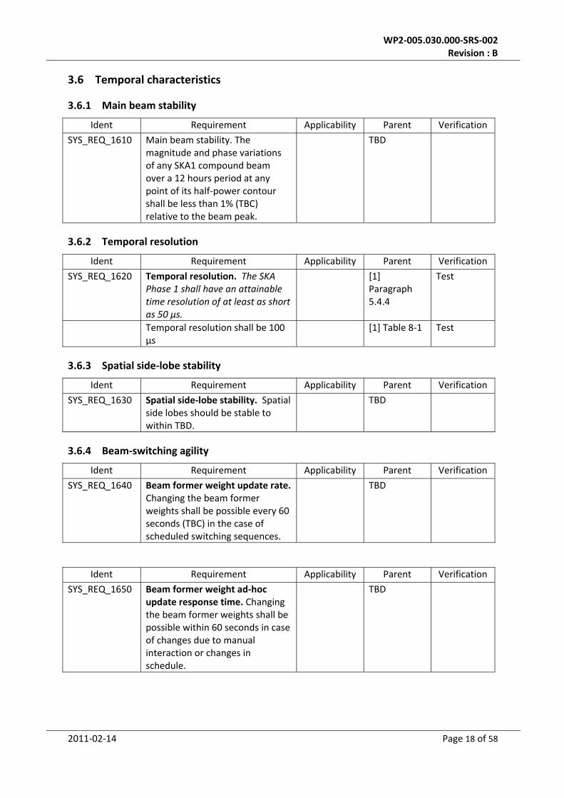
3.6.1 Main beam stability
Ident Requirement Applicability Parent Verification
SYS_REQ_1610 Main beam stability. The magnitude and phase variations of any SKA1 compound beam over a 12 hours period at any point of its half‐power contour shall be less than 1% (TBC) relative to the beam peak.
TBD
3.6.2 Temporal resolution
Ident Requirement Applicability Parent Verification
SYS_REQ_1620 Temporal resolution. The SKA Phase 1 shall have an attainable time resolution of at least as short as 50 μs.
[1] Paragraph 5.4.4
Test
Temporal resolution shall be 100 μs
[1] Table 8‐1 Test
3.6.3 Spatial side‐lobe stability
Ident Requirement Applicability Parent Verification
SYS_REQ_1630 Spatial side‐lobe stability. Spatial side lobes should be stable to within TBD.
TBD
3.6.4 Beam‐switching agility
Ident Requirement Applicability Parent Verification
SYS_REQ_1640 Beam former weight update rate. Changing the beam former weights shall be possible every 60 seconds (TBC) in the case of scheduled switching sequences.
TBD
Ident Requirement Applicability Parent Verification
SYS_REQ_1650 Beam former weight ad‐hoc update response time. Changing the beam former weights shall be possible within 60 seconds in case of changes due to manual interaction or changes in schedule.
TBD

WP2‐005.030.000‐SRS‐002 Revision : B
2011‐02‐14 Page 19 of 58
Ident Requirement Applicability Parent Verification
SYS_REQ_1660 Beam‐switching downtime flagging. Observation data (specify: both uv(w)‐data and tied array beams) acquired during a change of beam direction shall be flagged.
TBD
3.6.5 Frequency switching agility
Ident Requirement Applicability Parent Verification
SYS_REQ_1670 The SKA shall be able to ‘switch between observing frequencies within 10 minutes or less’ (in the band 0.8–3 GHz)
Mandatory [1] Paragraph 6.4.4 and Table 6‐2
Test
‘near simultaneous access to multiple frequencies’
[1] Table 8‐1
3.7 Polarisation characteristics
Ident Requirement Applicability Parent Verification
SYS_REQ_1710 Beam polarization stability. The polarization properties of the beams shall be stable enough to allow their calibration to better than 0.5% (TBC)
Ident Requirement Applicability Parent Verification
SYS_REQ_1720 External calibration measurements shall be necessary at a rate of no more than once per hour (TBC).
TBD
Ident Requirement Applicability Parent Verification
SYS_REQ_1730 Stokes parameters. SKA1 shall provide visibility data in all four Stokes parameters.
TBD
Ident Requirement Applicability Parent Verification
SYS_REQ_1740 Instrumental polarisation. The polarisation introduced by the instrument, after calibration, shall be less than 0.5% of the total intensity. (TBC)
TBD

WP2‐005.030.000‐SRS‐002 Revision : B
2011‐02‐14 Page 20 of 58
3.8 RFI avoidance
Ident Requirement Applicability Parent Verification
SYS_REQ_1810 The SKA1 shall have limited (TBD) susceptibility to bursty/spiky RFI (for pulsars, transients)
TBD
Ident Requirement Applicability Parent Verification
SYS_REQ_1820 Transient RFI detection. The post station level processing shall detect and flag invalid data.
TBD
Note: Section to be expanded.
3.9 Imaging characteristics
3.9.1 Instantaneous field of view
Ident Requirement Applicability Parent Verification
SYS_REQ_1910 Instantaneous field of view
‘These requirements imply a field of view greater than 5 degrees.’
[1] Paragraph 2.3.5
Ident Requirement Applicability Parent Verification
SYS_REQ_1920 Field of view imaging. It shall be possible to image the entire field of view
TBD
3.9.2 Imaging dynamic range
Ident Requirement Applicability Parent Verification
SYS_REQ_1940 Imaging dynamic range. SKA1 shall be able to provide an imaging dynamic range for continuum imaging (thermal noise imaging to classical (micro Jansky (Jy)) confusion limits) of at least:
35dB for the band 200MHz‐1.4 GHz
Mandatory [1] Table 8‐2
‘studies of star formation at high redshift with a continuum deep field require a dynamic range of 74 dB in imaging’
[1] Paragraph 7.4 and Table 8‐2

WP2‐005.030.000‐SRS‐002 Revision : B
2011‐02‐14 Page 21 of 58
3.9.3 Pointing accuracy
The mechanical and electronic pointing accuracy requirements of the dishes and the AAs are listed
below.
Ident Requirement Applicability Parent Verification
SYS_REQ_1950 Dish beam absolute pointing accuracy. The pointing accuracy of the dish beams is: TBD
TBD
Ident Requirement Applicability Parent Verification
SYS_REQ_1960 AA beam absolute pointing accuracy. The pointing accuracy of the AA beams is: TBD
TBD
3.9.4 Pointing estimation accuracy
The mechanical and electronic pointing estimation accuracy requirements of the dishes and the AAs,
are listed below.
Ident Requirement Applicability Parent Verification
SYS_REQ_1970 Dish beam pointing estimation accuracy. The pointing estimation accuracy of the dish beams is: TBD
TBD
Ident Requirement Applicability Parent Verification
SYS_REQ_1980 AA beam pointing estimation accuracy. The pointing estimation accuracy of the AA beams is: TBD
TBD
3.10 Monitoring and Control (M&C) Function
Monitoring And Control is a central system responsible for acquiring monitoring data and for control
of the SKA1 systems. It has a level of autonomy and its sub‐systems are distributed to local areas.
3.10.1 Top‐level requirements
Ident Requirement Applicability Parent Verification
SYS_REQ_2110 M&C. SKA1 shall provide a monitoring and control function.
TBD

WP2‐005.030.000‐SRS‐002 Revision : B
2011‐02‐14 Page 22 of 58
Ident Requirement Applicability Parent Verification
SYS_REQ_2120 M&C purpose. The monitoring and control function shall ensure that all parts of the system work together coherently. All control functions, except certain local maintenance functions, are part of the M&C system.
TBD
Ident Requirement Applicability Parent Verification
SYS_REQ_2130 M&C failure detection. The monitoring and control function shall ensure that failures in hardware, software or signal transport are detected and reported.
TBD
Ident Requirement Applicability Parent Verification
SYS_REQ_2140 M&C autonomy. The monitoring and control function shall take autonomous action to ameliorate failures where possible and support a fail‐safe philosophy.
TBD
Ident Requirement Applicability Parent Verification
SYS_REQ_2150 M&C shall take autonomous action in safety critical situations such as system power failure, over‐temperature, and storms (dish‐stowing).
TBD
Ident Requirement Applicability Parent Verification
SYS_REQ_2160 M&C transparency. The monitoring and control function shall give user transparent and hierarchical access to the instruments functions and parameters.
TBD
Ident Requirement Applicability Parent Verification
SYS_REQ_2190 M&C remote operation. The monitoring and control function shall be designed to operate the instrument fully remotely.
TBD

WP2‐005.030.000‐SRS‐002 Revision : B
2011‐02‐14 Page 23 of 58
Ident Requirement Applicability Parent Verification
SYS_REQ_2210 M&C performance monitoring. The monitoring and control function shall provide TBD performance monitoring data to users.
TBD
Ident Requirement Applicability Parent Verification
SYS_REQ_2220 M&C monitoring data. All SKA1 subsystems shall provide monitoring data to the monitoring and control function (for performance monitoring and closed‐loop control functions)
TBD
Ident Requirement Applicability Parent Verification
SYS_REQ_2230 M&C logging. The monitoring and control function shall provide for a long‐term logging sub‐function with workflow support for the Operational Team and with sufficient information to relate system events to artefacts in the data.
TBD
Ident Requirement Applicability Parent Verification
SYS_REQ_2240 M&C observation interrupt. It shall be possible to abort an observation if monitor parameters exceed user specified limits (including RFI mitigation performance indication parameters).
TBD
Ident Requirement Applicability Parent Verification
SYS_REQ_2250 M&C calibration information. Individual element calibration information shall be available to the measurement function.
TBD
The requirements on the M&C function related to Health and Safety still needs to be analysed,
verified and added.

WP2‐005.030.000‐SRS‐002 Revision : B
2011‐02‐14 Page 24 of 58
3.10.2 Control requirements
Requirements regarding control of the instrument (configuration of beam forming, correlation etc)
Ident Requirement Applicability Parent Verification
SYS_REQ_2310 Control system. SKA1 shall have a control system that actively controls all system settings in the instrument.
TBD
Ident Requirement Applicability Parent Verification
SYS_REQ_2320 Control system autonomy. The control system shall be capable of autonomously calculating system settings in response to changes in instrument status, environment or measurement results.
TBD
Ident Requirement Applicability Parent Verification
SYS_REQ_2330 System settings activation. It shall be possible to activate the calculated system settings either automatically (autonomous control) or after explicit confirmation by the operator (manual control).
TBD
Ident Requirement Applicability Parent Verification
SYS_REQ_2340 System setting activation autonomy. It shall be possible to specify when settings should be activated automatically and when they need to be confirmed by the operator.
TBD
Ident Requirement Applicability Parent Verification
SYS_REQ_2350 Schedule update. It shall be possible to receive and accept updated schedules before the end‐time of the currently active schedule has expired.
TBD

WP2‐005.030.000‐SRS‐002 Revision : B
2011‐02‐14 Page 25 of 58
3.10.3 Monitoring requirements
Requirements regarding monitoring the status of the instrument (configuration and health)
Ident Requirement Applicability Parent Verification
SYS_REQ_2410 Monitoring data consolidation. It shall be possible to consolidate monitoring information to produce high‐level monitoring information from low‐level monitoring information.
TBD
Ident Requirement Applicability Parent Verification
SYS_REQ_2420 Subsystem‐M&C action reports. Subsystems shall report completion of actions to M&C
TBD
Ident Requirement Applicability Parent Verification
SYS_REQ_2430 M&C summary reports. It shall be possible for all user roles (specification of these roles TBD) to produce summarized historical monitoring information.
TBD
Ident Requirement Applicability Parent Verification
SYS_REQ_2440 Control data augmentation. The results of control actions shall be verified with measurements made expressly for the purpose.
TBD
If the normal measurement sequence does not provide for control verification in a timely fashion, such measurements shall be made out of sequence.
Ident Requirement Applicability Parent Verification
SYS_REQ_2450 Monitoring information consolidation. It shall be possible to consolidate monitoring information both on the physical instrument status and on designated logical concepts like observation, correlator.
TBD

WP2‐005.030.000‐SRS‐002 Revision : B
2011‐02‐14 Page 26 of 58
3.11 Data Acquisition Characteristics
This section describes the functions in the acquisition and initial processing path. This includes the
definition of observation modes (synthesis imaging, tied array, fly’s eye, pulsar detection) and of
intermediate and final data products. Also the functional and performance requirements for RFI
mitigation, the data transport network and some derived performance parameters for data handling
are listed here.
Note: Section to be expanded.
3.12 Observational Modes
This section identifies the top‐level observational modes.
3.12.1 Top level modes
Ident Requirement Applicability Parent Verification
SYS_REQ_2710 Synthesis imaging mode. SKA1 shall provide a synthesis imaging mode where compound beams are correlated to form visibilities.
TBD
Ident Requirement Applicability Parent Verification
SYS_REQ_2720 Visibilities. In synthesis imaging mode it shall be possible to form visibilities between all corresponding monochromatic compound beams (same frequency, same direction) from all dishes or all aperture arrays (stations). This means that the central processing function should be able to handle the full data stream from the dishes or aperture arrays in synthesis imaging mode.
TBD
Ident Requirement Applicability Parent Verification
SYS_REQ_2730 Tied array mode. SKA1 shall provide a tied array mode where the signals from all dishes are phased up, after real‐time correction of instrumental effects, and transformed back into time series for pulsar processing.
TBD

WP2‐005.030.000‐SRS‐002 Revision : B
2011‐02‐14 Page 27 of 58
Ident Requirement Applicability Parent Verification
SYS_REQ_2740 Fly’s eye mode. SKA1 shall provide a fly’s eye mode (TBC). In this mode the Autocorrelations of all single dishes / aperture (sub)arrays are recorded. Each dish / sub‐array is tracking a different position on the sky.
TBD
Ident Requirement Applicability Parent Verification
SYS_REQ_2750 Aggregate mode. SKA1 shall provide an aggregate mode in which bandwidth is exchanged for spatial coverage in the correlator.
TBD
Ident Requirement Applicability Parent Verification
SYS_REQ_2760 Real‐time calibration. SKA1 shall provide instrumental real‐time calibration functions in all observational modes.
TBD
Ident Requirement Applicability Parent Verification
SYS_REQ_2770 Re‐processing archive data. It shall be possible to re‐process data retrieved from archive. To which extent this will be supported needs further discussion.
TBD
3.12.2 Data Products
Ident Requirement Applicability Parent Verification
SYS_REQ_2810 Automated data products. SKA1 shall be able to produce final data products based on automated and interactive (manual) processing of acquired data.
TBD
Ident Requirement Applicability Parent Verification
SYS_REQ_2820 Data product types. SKA1 shall produce recordable intermediate data products, for example pulsar voltage time series and RFI statistics.
TBD

WP2‐005.030.000‐SRS‐002 Revision : B
2011‐02‐14 Page 28 of 58
4 Operational Requirements
4.1 General
This section states general operational requirements.
Ident Requirement Applicability Parent Verification
SYS_REQ_3110 Up‐time. SKA1 shall be aimed to be operated continuously (7 days per week 24 hours per day).
TBD
Ident Requirement Applicability Parent Verification
SYS_REQ_3130 Remote M&C from sites. It shall be possible for the operator to control and monitor the SKA1 instrument from the SKA station sites and core site.
TBD
Ident Requirement Applicability Parent Verification
SYS_REQ_3140 Physical access security. The system shall provide security to prevent unauthorized physical access to facilities and resources.
TBD
To be added: security measures for other aspects such as network access, server access, encryption
of M&C messages.
4.2 Routine operations
This section gives system level requirements for the routine operations of SKA1.
Ident Requirement Applicability Parent Verification
SYS_REQ_3150 Reconfiguration time. Reconfiguration of SKA1 from one observational mode to another shall not take longer than 5 minutes (TBC) provided all software applications are present at their designated location.
TBD

WP2‐005.030.000‐SRS‐002 Revision : B
2011‐02‐14 Page 29 of 58
4.3 Start‐up and shutdown
This section gives system level requirements for SKA1 start‐up and shutdown, including check‐out at
initialization.
Ident Requirement Applicability Parent Verification
SYS_REQ_3160 Full remote control. It shall be possible to control all SKA1 functions from the operational centre, without requiring physical access to the instrument, including start‐up and shut down.
TBD
Ident Requirement Applicability Parent Verification
SYS_REQ_3170 Start‐up sequence. The start‐up of SKA1 functions shall follow a pre‐defined sequence taking not longer than:
TBD
10 minutes for a hot start (= restart)
24 hours for a cold start
To be added: definition of hot and cold start.
Ident Requirement Applicability Parent Verification
SYS_REQ_3180 Start‐up and shut‐down individual antenna systems. It shall be possible to start‐up or shutdown individual dishes or aperture arrays without disturbance [TBC] of routine operations.
TBD
Ident Requirement Applicability Parent Verification
SYS_REQ_3190 Shut‐down sequence. The shutdown of SKA1 shall follow a pre‐defined sequence taking not longer than TBD minutes. SKA1 shall also have an emergency shut‐down for wind (stowing dishes), lightning, and electric power anomalies.
TBD

WP2‐005.030.000‐SRS‐002 Revision : B
2011‐02‐14 Page 30 of 58
Ident Requirement Applicability Parent Verification
SYS_REQ_3210 Control over start‐up and shut‐down. Initialization of shut‐down and start‐up sequences shall be restricted to designated operators and engineers. To be defined: security requirements on different access levels (e.g. engineering mode).
TBD
Ident Requirement Applicability Parent Verification
SYS_REQ_3220 Start‐up and shut‐down dependencies. Any dependencies in the start‐up and shutdown sequences shall be automatically verified (so they do not depend on operator intervention).
TBD
Ident Requirement Applicability Parent Verification
SYS_REQ_3230 Subsystem shut‐down. The shutdown of pre‐defined parts of the SKA1 system shall have no (TBC) impact on SKA1 operations after appropriate re‐calibration performed automatically.
TBD
Ident Requirement Applicability Parent Verification
SYS_REQ_3240 Initial check‐out. SKA1 shall be designed to enable an operational readiness check, including redundancies, prior to commencement of any SKA1 operations (initial check‐out).
TBD
Ident Requirement Applicability Parent Verification
SYS_REQ_3250 Operational readiness check. The operational readiness check shall not take longer to complete than 5 minutes.
TBD

WP2‐005.030.000‐SRS‐002 Revision : B
2011‐02‐14 Page 31 of 58
4.4 Failure management1
4.4.1 General
General requirements regarding failure management
Ident Requirement Applicability Parent Verification
SYS_REQ_3310 Personnel safety. As far as possible, no single failure in the SKA1 shall lead to personnel safety hazards.
TBD
Ident Requirement Applicability Parent Verification
SYS_REQ_3320 Failure propagation. Failures in one of the SKA1 subsystems shall not lead to failures in other subsystems.
TBD
Ident Requirement Applicability Parent Verification
SYS_REQ_3330 Operator command safety. No single operator command shall cause catastrophic, serious, or major consequences.
TBD
Ident Requirement Applicability Parent Verification
SYS_REQ_3340 Voltage transients consequences . No voltage‐transients or "cut‐off" of electrical power shall lead to catastrophic or serious consequences. This includes voltage transients applied to the input of the receivers.
TBD
Ident Requirement Applicability Parent Verification
SYS_REQ_3350 Operator command absence. The absence of operator commands shall not cause catastrophic or serious consequences.
TBD
Ident Requirement Applicability Parent Verification
SYS_REQ_3360 Single‐point failures. Single‐point‐failures in the design shall be listed.
TBD
1 Section still to be aligned with Logistic Engineering Management Plan.

WP2‐005.030.000‐SRS‐002 Revision : B
2011‐02‐14 Page 32 of 58
Ident Requirement Applicability Parent Verification
SYS_REQ_3370 Single‐point failure justification. Each‐single‐point failure in the design shall be justified, and assessed against alternative design(s) where this single‐point‐failure would not occur.
TBD
Ident Requirement Applicability Parent Verification
SYS_REQ_3380 Single‐point failure watchdog. The correct functioning of each single‐point‐failure in the design shall be monitored by a watchdog function.
TBD
Ident Requirement Applicability Parent Verification
SYS_REQ_3410 Failing equipment. Failing equipment shall not provide data (TBC). Failing equipment shall indicate the problem if power is on, and the control function shall take appropriate measures.
TBD
4.4.2 Detection and reporting
Requirements regarding failure detecting equipment and how failures are to be reported including
level of detection.
Ident Requirement Applicability Parent Verification
SYS_REQ_3520 Status report availability time. The status report of the functioning of a subsystem shall be available in 5 seconds.
TBD
Ident Requirement Applicability Parent Verification
SYS_REQ_3530 Status report request. The status report of a subsystem shall reflect the functioning of the subsystem at or after the operator request has been submitted to the system.
TBD

WP2‐005.030.000‐SRS‐002 Revision : B
2011‐02‐14 Page 33 of 58
Ident Requirement Applicability Parent Verification
SYS_REQ_3540 Status report scope. The status report shall display the status of a function, together with the system time the status was determined.
TBD
4.4.3 Diagnosis and recovery
Requirements regarding distinguishing of failures and how failures are to be recovered from
Ident Requirement Applicability Parent Verification
SYS_REQ_3610 System interrogation reply. Each dish or aperture array system shall have the capability to answer to an operator interrogation, in case of detected failures at the dish, which antenna chain has failed.
TBD
Ident Requirement Applicability Parent Verification
SYS_REQ_3620 System autonomous and manual control modes. The system shall have the capability to be operated by an operator in an autonomous mode, and in a manual control mode.
TBD
Ident Requirement Applicability Parent Verification
SYS_REQ_3630 Autonomous malfunctioning actions. In the autonomous mode, all malfunctioning equipment and/or stations may be switched off autonomously, and a message with all details of this action shall be brought to the attention of the operator, and recorded in the systems log‐file.
TBD
Ident Requirement Applicability Parent Verification
SYS_REQ_3640 Manual control switch on/off. In the manual control mode, the operator shall have the capability to switch on or off all equipment and/or stations.
TBD

WP2‐005.030.000‐SRS‐002 Revision : B
2011‐02‐14 Page 34 of 58
Ident Requirement Applicability Parent Verification
SYS_REQ_3650 Operator actions logging. Operator actions shall be recorded in the systems log‐file, in such a way that a complete picture of all correct functioning and/or all malfunctioning equipment, together with their operational and/or switch off statuses, can be achieved.
TBD
Ident Requirement Applicability Parent Verification
SYS_REQ_3660 Recovery actions. It shall be possible to take recovery actions without consequences for other parts of SKA1; the system shall minimize impact of recovery actions.
TBD
Ident Requirement Applicability Parent Verification
SYS_REQ_3670 Autonomous recovery. SKA1 shall be able to recover autonomously in case of failures that are classified as minor or negligible.
TBD
Ident Requirement Applicability Parent Verification
SYS_REQ_3680 Effect of disabled units. The SKA1 design shall ensure that disabled units do not corrupt the remaining system.
TBD
4.4.4 Lifetime
Operational lifetime requirements, including spare parts and supporting equipment
Ident Requirement Applicability Parent Verification
SYS_REQ_3710 Continuous operation period. SKA1 shall be designed for a continuous operational period of 6 month. After this time maintenance may be necessary, e.g. exchange/cleaning of air‐conditioning filters and refurbishment of cryogenic systems.
TBD

WP2‐005.030.000‐SRS‐002 Revision : B
2011‐02‐14 Page 35 of 58
Ident Requirement Applicability Parent Verification
SYS_REQ_3720 Minimum life time. SKA1 shall be designed for a minimum life time of TBD years, including initial installation, testing and commissioning period.
TBD
Ident Requirement Applicability Parent Verification
SYS_REQ_3730 Availability. The average availability of SKA1 during the operational period shall be better than 90% (TBC). Availability is defined here as being available for scheduled observations in at least one of the supported operational modes.
TBD
Ident Requirement Applicability Parent Verification
SYS_REQ_3740 Upgradeability SKA1 shall be upgradable.
TBD
Ident Requirement Applicability Parent Verification
SYS_REQ_3750 Life‐time extension. Large scale maintenance and/or an upgrade shall give the possibility to reach a life time of 50 years (TBC).
TBD
4.5 Maintenance2
Requirements regarding maintenance concept, corrective and preventive
Ident Requirement Applicability Parent Verification
SYS_REQ_3810 Full fail rate. SKA1 shall be designed to fully fail less than two times per year (TBC), the number determined as average over its operational period.
TBD
Note: Full failure is defined here as an unscheduled inability to operate in any observational mode
for more than two hours due to malfunctioning of one or more subsystems. The requirement applies
to the period after initial commissioning of the system or any upgraded components.
2 Section still to be aligned with Logistic Engineering Management Plan.

WP2‐005.030.000‐SRS‐002 Revision : B
2011‐02‐14 Page 36 of 58
Ident Requirement Applicability Parent Verification
SYS_REQ_3820 Repair period. The maximum period of repair once a failure of SKA1 has been established, shall be 1 (TBC) week. Here, a failure is defined as not being able to meet the scientific specifications due to (sub)system failure(s).
TBD
Ident Requirement Applicability Parent Verification
SYS_REQ_3830 Non‐availability information. All users with scheduled measurements during the failure period shall be informed of the non‐availability of the system
TBD
Ident Requirement Applicability Parent Verification
SYS_REQ_3840 Data loss due to power outage. All subsystems shall not lose more than 4 hours of acquired or processed measurement data (not yet permanently stored) as a result of an outage in the external power supply.
TBD
Ident Requirement Applicability Parent Verification
SYS_REQ_3850 Autonomous restart after power outage. All subsystems shall have the capability to restart autonomously and without failures, after an outage in external power supply.
TBD
Ident Requirement Applicability Parent Verification
SYS_REQ_3860 System availability after restart. All subsystems shall be available within 5 minutes (TBC) after restart. (Note – there may be subsystems such as cryo coolers that will probably not comply to the requirement and will need to be handled differently).
TBD

WP2‐005.030.000‐SRS‐002 Revision : B
2011‐02‐14 Page 37 of 58
Ident Requirement Applicability Parent Verification
SYS_REQ_3870 Software/firmware re‐installation. All software/firmware in SKA1 shall allow its re‐installation.
TBD
Ident Requirement Applicability Parent Verification
SYS_REQ_3880 Software/firmware upgrades. It shall be possible to replace all software/firmware configuration items in SKA1 through software‐upgrades, initiated by an engineer.
TBD
Ident Requirement Applicability Parent Verification
SYS_REQ_3890 Software code identification. Software configuration items shall provide unambiguous inputs to allow the maintenance of a configuration management database.
TBD
Ident Requirement Applicability Parent Verification
SYS_REQ_3910 Software code identification response time. The software identification shall be available to the operator within 10 seconds (TBC) after the request was made.
TBD
Ident Requirement Applicability Parent Verification
SYS_REQ_3920 Subsystem maintenance functions. All subsystems shall include functions that allow maintenance of hardware and software.
TBD

WP2‐005.030.000‐SRS‐002 Revision : B
2011‐02‐14 Page 38 of 58
4.6 Disposal phase
Requirements regarding used materials, ecological aspects, programmatic reserve.
Ident Requirement Applicability Parent Verification
SYS_REQ_4110 Environmental rule compliancy. The SKA1 design shall be fully compliant to all environmental rules applicable to the SKA site.
TBD
Ident Requirement Applicability Parent Verification
SYS_REQ_4120 Lasting environmental effects. SKA1 shall be designed to have no lasting adverse environmental effects on the facility and site.
TBD
5 Design constraints
This chapter specifies the design constraining requirements such as determined by the environment
the instrument will be placed in or relating to mechanical and electrical guidelines, product
assurance, safety hazards, government regulations etc. Some requirements provided in this chapter
which appear to be only applicable at subsystem level may be moved to the "supporting
specifications" as these are established.
5.1 Environmental Requirements
5.1.1 General
General environmental requirements
Ident Requirement Applicability Parent Verification
SYS_REQ_5110 Climatic and environmental conditions. SKA1 shall be designed or protected against any deterioration leading to failure to meet the requirements specified herein caused by climatic and environmental conditions during its complete lifetime (both operating and non‐operating).
TBD
Ident Requirement Applicability Parent Verification
SYS_REQ_5120 Compliancy with local environment. The design of SKA1 shall be appropriate (TBD) for operation in the natural environment for the geographical deployment location of the SKA1.
TBD

WP2‐005.030.000‐SRS‐002 Revision : B
2011‐02‐14 Page 39 of 58
Ident Requirement Applicability Parent Verification
SYS_REQ_5130 Transportation conditions. SKA1 equipment shall be designed for the induced transportation environment appropriate to the mode of transport being used (road, air, sea, etc.) between place of manufacturing and final installation on the SKA site (to be included: packaging requirements).
TBD
5.1.2 Site and infrastructure requirements
General requirements for station sites, building locations, connecting roads
Ident Requirement Applicability Parent Verification
SYS_REQ_5210 Building climate conditioning. Buildings or parts of buildings containing central processing equipment and operator areas shall have a climatic conditioning system which can control the temperature within the range of 18 ºC to 23 ºC and the humidity within the range of 50 % to 70 % independent of weather conditions.
TBD
Ident Requirement Applicability Parent Verification
SYS_REQ_5220 Facilities and equipment intrusion. SKA1 equipment and operating facilities shall be adequately protected against intrusion by unauthorized persons or by “larger” wandering animals.
TBD
5.1.3 Contamination and precipitation
Ident Requirement Applicability Parent Verification
SYS_REQ_5230 Precipitation. SKA1 equipment shall be able to operate without degradation of the performance during any type of precipitation (to be specified).
TBD

WP2‐005.030.000‐SRS‐002 Revision : B
2011‐02‐14 Page 40 of 58
Ident Requirement Applicability Parent Verification
SYS_REQ_5240 Pollution and contamination protection. SKA1 equipment shall be adequately protected against performance degradation caused by contaminating particles (dust, sand etc), polluted air or any precipitation.
TBD
5.1.4 Climatic requirements
Ident Requirement Applicability Parent Verification
SYS_REQ_5310 Humidity. SKA1 equipment located at the dishes or aperture arrays or outside the central processing and operating facilities shall be able to withstand moisture and humidity levels up to 100 % RH.
TBD
Ident Requirement Applicability Parent Verification
SYS_REQ_5320 Allowable air temperature range. SKA1 equipment located at the dishes or aperture arrays or outside the central processing and operating facilities shall be able to withstand (non‐operating if necessary) an outside air temperature within the range of ‐15 ºC (TBC) to +60 ºC (TBC).
TBD
Ident Requirement Applicability Parent Verification
SYS_REQ_5330 Air temperature operation range. SKA1 equipment located at the dishes or aperture arrays or outside the central processing and operating facilities shall be able to operate within specification if the outside air temperature is within the range of ‐5 ºC (TBC) to +50 ºC (TBC).
TBD

WP2‐005.030.000‐SRS‐002 Revision : B
2011‐02‐14 Page 41 of 58
Ident Requirement Applicability Parent Verification
SYS_REQ_5340 Wind velocities. SKA1 equipment shall be able to survive wind velocities up to 160 km/hr (TBC), and shall operate within normal specification ranges for wind velocities up to 40 km/hr (TBC).
TBD
5.1.5 Radio Frequency Interference
Protection and measures against interfering signals from outside the instrument
Ident Requirement Applicability Parent Verification
SYS_REQ_5410 Damaging interference levels. SKA1 shall not be damaged by RFI signals less than TBD V/m.
TBD
Ident Requirement Applicability Parent Verification
SYS_REQ_5420 EM immunity. SKA1 shall not be susceptible to RFI signals, in‐band or out‐band, other than via the receptors.
TBD
Ident Requirement Applicability Parent Verification
SYS_REQ_5430 ADC clipping. The dynamic range of the ADC’s in the SKA1 shall be such that no clipping will occur. Clipping occurs when the range of the input signal voltages to the ADC is larger than the ADC voltage range. The number of ADC bits shall therefore be sufficient to prevent clipping due to strong interfering signals such as aircraft Distance Measuring Equipment (DME) and satellite signals.
TBD
5.1.6 Electro Magnetic Compatibility
During each phase of the SKA1 life, from equipment integration until its end of life, the instrument
shall neither cause disturbance to other systems, nor suffer loss of performance due to other
systems or to the RFI environment.

WP2‐005.030.000‐SRS‐002 Revision : B
2011‐02‐14 Page 42 of 58
The ability of the SKA1 to perform its mission within the required performance shall be
demonstrated by tests, analysis, inspection, verification of records or demonstration according to
the system verification requirements.
Ident Requirement Applicability Parent Verification
SYS_REQ_5610 EMC safety margin. The EMC safety margin, which is defined as the ratio between susceptibility threshold and the interference at any point within the system, shall be greater than TBD dB.
TBD
Ident Requirement Applicability Parent Verification
SYS_REQ_5620 EMC compatibility marking. All "off‐the‐shelf" equipment applied within SKA1 shall posses as a minimum the host country EMC marking, including electrical and electronic supporting and infrastructural equipment.
TBD
Ident Requirement Applicability Parent Verification
SYS_REQ_5630 Grounding concept. A hybrid grounding concept as shown in figures TBD shall be used for EMC purposes. Ground loops involving DC, and low frequency AC, currents shall be avoided inside the system. Intentional currents through structure are not permitted. (to be elaborated)
TBD
Ident Requirement Applicability Parent Verification
SYS_REQ_5640 EMC design efforts. Maximum effort (to be detailed) shall be put into designing signal interfaces to withstand noisy environments and to minimize the generation of excessive noise.
TBD
Emission requirements and tests. Emission requirements, both conducted and radiated) and tests
(to be elaborated)
Susceptibility requirements and tests. Susceptibility requirements and tests (to be elaborated)

WP2‐005.030.000‐SRS‐002 Revision : B
2011‐02‐14 Page 43 of 58
5.1.7 Self‐generated RFI environment
Ident Requirement Applicability Parent Verification
SYS_REQ_2910 Self‐generated RFI susceptibility. Interference due to self‐generated RFI shall not degrade the performance of the instrument by greater than 1% by any measure (TBC).
TBD
5.1.8 Lightning
Ident Requirement Applicability Parent Verification
SYS_REQ_5710 Lightning discharge susceptibility. The SKA1 shall be able to withstand the electromagnetic field impact defined in TBD during operation or in any other mode without any damage or characteristics degradation because of a lightning discharge.
TBD
Ident Requirement Applicability Parent Verification
SYS_REQ_5720 Lightning protection. SKA1 dedicated buildings and equipment located on sites shall be protected to minimize the effects of a direct lightning strike using certified methods (e.g. as described in NEN 1014).
TBD
Ident Requirement Applicability Parent Verification
SYS_REQ_5730 Lightning discharge flagging. Observation data taken during a lightning strike shall be flagged.
TBD
Direct strikes. TBC
5.1.9 Grounding
Requirements regarding grounding of equipment, personnel safety and instrument performance
(electrical grounding concept), use of design standards

WP2‐005.030.000‐SRS‐002 Revision : B
2011‐02‐14 Page 44 of 58
Ident Requirement Applicability Parent Verification
SYS_REQ_5810 Safety ground. Electrical safety ground shall be designed according to the regulations imposed by the local government.
TBD
5.1.10 Corrosion
Ident Requirement Applicability Parent Verification
SYS_REQ_5820 Corrosion protection. SKA1 equipment and buildings shall be protected against corrosion.
TBD
Ident Requirement Applicability Parent Verification
SYS_REQ_5830 Corrosion protection in air flows. SKA1 electronics and connectors in areas with a higher air flow (for cooling) or outdoor environment shall be additionally protected against corrosion.
TBD
5.1.11 Seismicity
Ident Requirement Applicability Parent Verification
SYS_REQ_5910 Earthquakes. SKA1 equipment and buildings shall be protected against earthquakes with a magnitude up to Richter 3.8 (TBC).
TBD
5.1.12 Other Aspects
Additional aspects that will need consideration in this chapter include:
Temperature and humidity o Operational
External/exposed equipment Internal equipment Human accessible and work areas
o Non operational (storage and transportation)
Exposure to rain o Operational with full performance o Survival
Hail o Survival
Ice and snow (TBC)
Lightning
WP2‐005.030.000‐SRS‐002 Revision : B
2011‐02‐14 Page 45 of 58
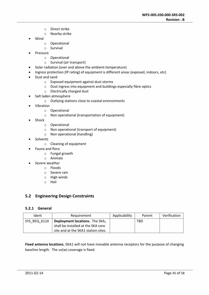
o Direct strike o Nearby strike
Wind o Operational o Survival
Pressure o Operational o Survival (air transport)
Solar radiation (over and above the ambient temperature)
Ingress protection (IP rating) of equipment is different areas (exposed, indoors, etc)
Dust and sand o Exposed equipment against dust storms o Dust ingress into equipment and buildings especially fibre optics o Electrically charged dust
Salt laden atmosphere o Outlying stations close to coastal environments
Vibration o Operational o Non operational (transportation of equipment)
Shock o Operational o Non operational (transport of equipment) o Non operational (handling)
Solvents o Cleaning of equipment
Fauna and flora o Fungal growth o Animals
Severe weather o Floods o Severe rain o High winds o Hail
5.2 Engineering Design Constraints
5.2.1 General
Ident Requirement Applicability Parent Verification
SYS_REQ_6110 Deployment locations. The SKA1 shall be installed at the SKA core site and at the SKA1 station sites.
TBD
Fixed antenna locations. SKA1 will not have movable antenna receptors for the purpose of changing
baseline length. The uv(w) coverage is fixed.

WP2‐005.030.000‐SRS‐002 Revision : B
2011‐02‐14 Page 46 of 58
5.2.2 Size and weight
The front‐end is defined as all equipment that is installed in the feedbox. The weight of this is TBD.
Ident Requirement Applicability Parent Verification
SYS_REQ_6210 Feed Payload volume. The SKA1 front‐end and cabling shall fit in the available feedboxes.
TBD
Ident Requirement Applicability Parent Verification
SYS_REQ_6220 , Feed payload mass limit. The total mass of any feed payload, including the RF cables to the ground, shall not exceed: TBD.
TBD
Note: this section needs to be expanded.
5.2.3 Materials and Processes
Use is to be made of adequate and (ecological) allowed permissible materials, deviations to be
approved by the project, including management of applied materials.
Ident Requirement Applicability Parent Verification
SYS_REQ_7110 Materials, Parts and Processes lists. Each subsystem supplier shall establish, collect, review and deliver the Materials, Parts and Processes lists including all the Materials, Parts and Processes intended for use in the SKA1 equipment by his suppliers and himself.
TBD
They shall reflect the current design at the time of issue.
The objectives are the following:
a) to ensure that all requirements of the program are met,
b) to verify the Materials, Parts and Processes activity of equipment suppliers,
c) to control and monitor the status of Materials, Parts and Processes in accordance with
program milestones and regulations

WP2‐005.030.000‐SRS‐002 Revision : B
2011‐02‐14 Page 47 of 58
Ident Requirement Applicability Parent Verification
SYS_REQ_7130 Parts availability. The estimated availability of the Parts and products obtained from Materials and Processes used shall be compatible with the final system’s life cycle (tests, storage, mission).
TBD
Ident Requirement Applicability Parent Verification
SYS_REQ_7140 Material environmental rule compliance. All materials used in the SKA1 design shall be fully compliant to all environmental rules applicable to the SKA1 core and remote sites.
TBD
Ident Requirement Applicability Parent Verification
SYS_REQ_7150 Long‐term environmental effects. Materials used in the SKA1 design shall not have any lasting effect on the site location.
TBD
Ident Requirement Applicability Parent Verification
SYS_REQ_7160 Maintenance free materials. Materials used for the parts subject to the outdoors environment shall be maintenance free. (TBC)
TBD
5.2.4 Marking
Components, (sub) systems, instruments, equipment, and materials shall be marked for
configuration control purposes and maintenance support purposes.
Ident Requirement Applicability Parent Verification
SYS_REQ_7210 Part identification. Each part, material or product shall be identified with a unique and permanent part or type number.
TBD
Ident Requirement Applicability Parent Verification
SYS_REQ_7220 Marking method. Method of marking shall be compatible with the nature of the item and its use.
TBD

WP2‐005.030.000‐SRS‐002 Revision : B
2011‐02‐14 Page 48 of 58
Ident Requirement Applicability Parent Verification
SYS_REQ_7230 Documentation marking. Identification numbers shall be marked on documentation and, where possible, on respective items.
TBD
5.2.5 Power and other utilities
Ident Requirement Applicability Parent Verification
SYS_REQ_7310 Mains supply. The SKA1 shall connect to the available power distribution at the SKA core and remote sites.
TBD
Ident Requirement Applicability Parent Verification
SYS_REQ_7320 Dish or AA power consumption. The power consumption of all equipment at any AA or dish station, including the motors driving the dishes, shall be less than TBD kVA.
TBD
Ident Requirement Applicability Parent Verification
SYS_REQ_7330 Observatory power consumption. The total power consumption of the SKA1 observatory shall be less than TBD kVA.
TBD
5.3 Quality Factors Requirements
Requirements related to the quality of the product.
5.3.1 General
Ident Requirement Applicability Parent Verification
SYS_REQ_7410 Quality standard. SKA1 equipment and electronics shall be developed and produced according to the ISO9001 (TBC) quality standard.
TBD

WP2‐005.030.000‐SRS‐002 Revision : B
2011‐02‐14 Page 49 of 58
Ident Requirement Applicability Parent Verification
SYS_REQ_7420 Field return rate. The field return rate of equipment shall be less than 0.5% (TBC) during installation and the first year full usage.
TBD
5.3.2 Workmanship
Good workmanship expected for mechanical, electrical and software production. It refers to the
physical characteristics relating to the level of quality introduced by the manufacturing and assembly
activities.
Ident Requirement Applicability Parent Verification
SYS_REQ_7510 General workmanship standards. General workmanship standards shall be applied as specified in the Product Assurance Plan (TBD) both for Software and Hardware production. These include ISO9001 (TBC).
TBD
Ident Requirement Applicability Parent Verification
SYS_REQ_7520 Scope of workmanship standards. SKA1 dedicated workmanship standards shall be specified in project dedicated documents
TBD
and shall: a) cover all phases of production, assembly and integration, testing, handling, and include clear requirements for acceptance/rejection criteria.
5.3.3 System Safety
Safety critical functions, propagation paths, design margins
Ident Requirement Applicability Parent Verification
SYS_REQ_7610 Design margins. The SKA1 design shall possess design margins to cover all uncertainties in environment, analysis and properties of the materials and processes used.
TBD

WP2‐005.030.000‐SRS‐002 Revision : B
2011‐02‐14 Page 50 of 58
5.3.4 Security
Ident Requirement Applicability Parent Verification
SYS_REQ_7720 User‐dependent accessibility. It shall be possible to specify on a per user basis which SKA1 facilities and resources (both hardware and software) may be accessed by the user.
TBD
5.3.5 Reliability3
Ident Requirement Applicability Parent Verification
SYS_REQ_7810 SKA1 equipment reliability. The reliability of SKA1 equipment to meet its performance requirements over a period of 10 years shall be greater than 99.4 % (TBC).
TBD
5.3.6 Maintainability4
Ident Requirement Applicability Parent Verification
SYS_REQ_7820 Tools and test equipment. The SKA1 design shall require a minimum of special tools and test equipment to perform assembly, integration and repair and maintenance activities.
TBD
Ident Requirement Applicability Parent Verification
SYS_REQ_7830 Inaccessible hardware maintenance. Inaccessible hardware or structures shall require no maintenance during operation and should have built in test capability when applicable.
TBD
3 Section still to be aligned with Logistic Engineering Management Plan.
4 Section still to be aligned with Logistic Engineering Management Plan.

WP2‐005.030.000‐SRS‐002 Revision : B
2011‐02‐14 Page 51 of 58
Ident Requirement Applicability Parent Verification
SYS_REQ_7840 Test and repair instructions. Test and repair instructions shall be written for fault detection and maintenance of the SKA1 equipment.
TBD
Ident Requirement Applicability Parent Verification
SYS_REQ_7850 Maintenance team size. It should be possible to execute regular maintenance jobs with not more than two (2) people per job.
TBD
5.3.7 Flexibility and upgradability
Ident Requirement Applicability Parent Verification
SYS_REQ_7860 Modular design. The SKA1 design (hardware and software) shall have a modular approach.
TBD
Ident Requirement Applicability Parent Verification
SYS_REQ_7870 System flexibility and expandability. The SKA1 design (hardware and software) shall provide flexibility and expandability to support anticipated areas of growth or changes in technology or mission. (e.g. in the field of but not limited to: network bandwidth, storage space, processing power)
TBD
5.3.8 Accessibility and testability
Requirements regarding the design of equipment, access in case of maintenance, trouble shooting,
test connectors etc
Ident Requirement Applicability Parent Verification
SYS_REQ_7880 Self‐test capability. The SKA1 design for both hardware and software shall provide self‐test capabilities.
TBD

WP2‐005.030.000‐SRS‐002 Revision : B
2011‐02‐14 Page 52 of 58
Ident Requirement Applicability Parent Verification
SYS_REQ_7890 Servicing point making. All servicing and test points shall be clearly marked using TBD labelling standards.
TBD
5.3.9 Transportability and storage
Requirements regarding transport of equipment, vibration and shock environment of different
transport possibilities
Ident Requirement Applicability Parent Verification
SYS_REQ_7910 Handling heavy equipment. SKA1 parts, test equipment or supporting equipment with mass exceeding 25 kg shall be provided with provisions for handling and transportation.
TBD
Ident Requirement Applicability Parent Verification
SYS_REQ_7920 Disassembly for transport. It shall be possible to disassemble SKA1 equipment for the reason of transportation or storage in its main parts.
TBD
Ident Requirement Applicability Parent Verification
SYS_REQ_7930 Long term storage. It shall be possible to store SKA1 equipment (spare parts) for 10 years without any degradation of its function or performance.
TBD
Ident Requirement Applicability Parent Verification
SYS_REQ_7935 If special storage facilities are needed they shall be supplied as part of the spares procurement.
TBD

WP2‐005.030.000‐SRS‐002 Revision : B
2011‐02‐14 Page 53 of 58
5.3.10 Life
Ident Requirement Applicability Parent Verification
SYS_REQ_7940 Reusability. Reusability of SKA1 equipment shall be ensured through design and by refurbishment and maintenance where this has been demonstrated as being cost effective.
TBD
Ident Requirement Applicability Parent Verification
SYS_REQ_7950 Spare parts. SKA1 spare parts shall have a storage life consistent with availability and use during the full operational lifetime of the SKA1 equipment to which it applies.
TBD
Ident Requirement Applicability Parent Verification
SYS_REQ_7960 Support equipment life‐time. SKA1 support equipment shall be designed to maintain SKA1 for 12 (TBC) years.
TBD
6 Interface Requirements
External Interfaces are defined as interactions or communications with the world outside SKA1.
Internal interfaces are defined as interactions or communications between or internal in SKA1
subsystems.
6.1 External Interfaces
6.1.1 Power
Ident Requirement Applicability Parent Verification
SYS_REQ_8110 Supply power. The power supplied to the SKA1 systems shall have the following characteristics (TBC): a) voltage 380 V +/‐ 10% b) 3 phases c) 50 Hz +/‐ 1 Hz
TBD

WP2‐005.030.000‐SRS‐002 Revision : B
2011‐02‐14 Page 54 of 58
Ident Requirement Applicability Parent Verification
SYS_REQ_8130 Central facility UPS. The power source to the central facility shall have back‐up provisions for controlled shut‐down (TBC).
TBD
6.1.2 Data synchronization
Ident Requirement Applicability Parent Verification
SYS_REQ_8140 Subsystem time standard. Each SKA1 AA or dish system shall maintain an internal time standard with an accuracy of TBD nanoseconds
TBD
Ident Requirement Applicability Parent Verification
SYS_REQ_8150 Central time standard. All SKA1 subsystems shall synchronize their internal time standards to the central timing standard with an accuracy of TBD nanoseconds.
TBD
6.2 Internal Interfaces
6.2.1 Power
Ident Requirement Applicability Parent Verification
SYS_REQ_8160 Limiting excessive currents. SKA1 equipment circuitry shall be protected against excessive currents by a current limiting device, which shall not itself produce excessive currents.
TBD
Ident Requirement Applicability Parent Verification
SYS_REQ_8170 Power surge protection. SKA1 sub‐systems shall be protected against power transients and surges.
TBD

WP2‐005.030.000‐SRS‐002 Revision : B
2011‐02‐14 Page 55 of 58
Ident Requirement Applicability Parent Verification
SYS_REQ_8180 Polarity mis‐connection protection. SKA1 equipment circuitry shall be protected against the effects of inadvertent wrong polarity connections. (TBC)
TBD
6.3 Synchronization
Ident Requirement Applicability Parent Verification
SYS_REQ_8210 Data time‐tagging. All dishes and aperture arrays shall time‐tag received and processed data with the accuracy of their internal time standard.
TBD
7 Support Requirements
7.1 Maintenance
Ident Requirement Applicability Parent Verification
SYS_REQ_9110 Test resources. SKA1 subsystems shall specify what special test resources they require in the operational phase.
TBD
7.2 Logistics
Logistic requirements during built‐up and operations, may include: system maintenance, software
support, system transportation modes, supply‐system requirements, impact on existing facilities,
and impact on existing equipment.
Ident Requirement Applicability Parent Verification
SYS_REQ_9130 Preventive maintenance. Preventive maintenance of SKA1 hardware shall be performed in accordance with the maintenance program established for SKA1.
TBD
8 Extensibility Requirements
Phase 1 of the SKA is to be followed by a Phase 2, designed to meet a superset of science
requirements given in AD1.

WP2‐005.030.000‐SRS‐002 Revision : B
2011‐02‐14 Page 56 of 58
8.1 Extension interfaces
Ident Requirement Applicability Parent Verification
SYS_REQ_10110 Dish/PAF interfaces. SKA1 Dishes shall be designed, built and verified such that they can accommodate Phased Array Feeds.
TBD
8.2 Extension performance
Ident Requirement Applicability Parent Verification
SYS_REQ_10120 Frequency Coverage. SKA1 Dishes shall be designed, built and verified such that they can meet AD1 optical requirements up to 10GHz.
TBD
Ident Requirement Applicability Parent Verification
SYS_REQ_10130 Polarization Purity. SKA1 feeds, receivers and digital processing subsystems shall be designed to provide the AD1 polarization purity requirement of 40dB.
TBD
Ident Requirement Applicability Parent Verification
SYS_REQ_10140 Imaging dynamic range. SKA1 elements shall be designed to provide an imaging dynamic range of 74 dB up to 10GHz
TBD
Ident Requirement Applicability Parent Verification
SYS_REQ_10150 Spectral dynamic range. SKA1 elements shall be designed to provide a spectral dynamic range of 67 dB.
TBD

WP2‐005.030.000‐SRS‐002 Revision : B
2011‐02‐14 Page 57 of 58
9 Quality Assurance Provisions
This section will describe the formal tests/verifications of System requirements specified in the body
of this specification.
Management and planning information pertaining to product verification and validation should be
described in the system Test and Evaluation Master Plan.
9.1 System Qualification testing
Tests shall mainly be performed to verify that the SKA1 complies to the performance requirements
specified in this specification.
An incremental qualification approach shall be adopted starting at Material level and culminating at
SKA1 system level in a Test & Qualification (T&Q) program. For existing products (COTS) proof of
qualification, including the specification, method of testing and results, will be utilised. No re‐
qualification of these products will be performed. However, wherever interfaces have been
modified/added, regression testing will be performed to confirm the integrity of the interface
against it’s original interface control specification.
The tests to be performed on the various subsystems and elements of the SKA1 will be described
here. It will include aspects such Factory Acceptance Tests and Site Acceptance Tests (stand alone
and integrated).
9.2 Test Methods
The requirements specified in this document shall be verified by one or more of the following test
methods:
• Inspection (I)
Verification shall be by visual examination, comparison with engineering data and simple
measurement without the use of precision measuring equipment.
• Test (T)
Verification shall be by analysis or review of test data recorded using special measurement
equipment and procedures.
• Demonstration (D)
Verification shall be by application of go/no go criteria without the use of elaborate
measurement equipment.
• Analysis (A)
Verification shall be by analysis or review of calculated or simulated data.

WP2‐005.030.000‐SRS‐002 Revision : B
2011‐02‐14 Page 58 of 58
Appendix 1. List of DRM technical specifications
The table below lists the quantities, their values and their units as specified in the SKA1 DRM . The units in the table below are defined by: Chapter; the
science cases as specified in the DRM, Frequency Range (MHz), survey speed (m4K‐2 degree2), Aeff/Tsys (m2K‐1), frequency resolution (kHz), temporal
resolution (s), polarization purity (dB), imaging dynamic range (dB), spectral dynamic range (dB), Observation type.