SK /SPK Space-saving right-angle precision with output …€¦ · sk+ spk+ 0 1000 2000 3000 4000...
38
SK + SPK + 0 1000 2000 3000 4000 5000 6000 700 600 500 400 300 200 175 150 125 100 75 50 25 5000 4000 3000 2000 1000 500 400 300 200 100 0 1000 2000 3000 4000 5000 6000 SK + 060 SK + 075 SK + 100 SK + 140 SK + 180 SPK + 075 SPK + 100 SPK + 140 SPK + 180 SPK + 210 SPK + 240 SK + /SPK + – Space-saving right-angle precision with output shaft SK + MF (example for i = 5) For applications in cyclic operation (DC ≤ 60%) or continuous operation (DC ≥ 60%) SPK + MF (example for i = 25) For applications in cyclic operation (DC ≤ 60%) or continuous operation (DC ≥ 60%) Quick size selection Max. input speed [rpm] Max. acceleration torque at output [Nm] Max. input speed [rpm] Max. acceleration torque at output [Nm] The representatives of our versatile hypoid gearhead with SP + compat- ible output shaft. SPK + gearheads with planetary stage are especially suitable for high-precision app- lications requiring higher power and torsional rigidity. 210
Transcript of SK /SPK Space-saving right-angle precision with output …€¦ · sk+ spk+ 0 1000 2000 3000 4000...

SK+
SPK+
0 1000 2000 3000 4000 5000 6000
700
600
500
400
300
200
175
150
125
100
75
50
25
5000
4000
3000
2000
1000
500
400
300
200
100
0 1000 2000 3000 4000 5000 6000
SK+ 060
SK+ 075
SK+ 100
SK+ 140
SK+ 180
SPK+ 075
SPK+ 100
SPK+ 140
SPK+ 180
SPK+ 210
SPK+ 240
SK+/SPK+ – Space-saving right-angle precision with output shaft
SK+ MF (example for i = 5)For applications in cyclic operation (DC ≤ 60%)or continuous operation (DC ≥ 60%)
SPK+ MF (example for i = 25)For applications in cyclic operation (DC ≤ 60%)or continuous operation (DC ≥ 60%)
Quick size selection
Max. input speed [rpm]
Max
. acc
eler
atio
n to
rque
at
out
put
[N
m]
Max. input speed [rpm]
Max
. acc
eler
atio
n to
rque
at
out
put
[N
m]
The representatives of our versatile hypoid gearhead with SP+ compat-ible output shaft. SPK+ gearheads with planetary stage are especially suitable for high-precision app-lications requiring higher power and torsional rigidity.
210

SK
+ / S
PK
+
• • • •
• • • • •
• • • •
• • • •
3 – 100 12 – 10000
≤ 4 ≤ 4
– ≤ 2
• •
• •
• •
• •
• •
• •
•
• •
• •
•
• •
• •
• •
• •
• •
• •
• •
• •
Rig
ht-a
ngle
gea
rhea
dsH
igh
En
d
Versions and Applications
Ratios c)
Torsional backlash [arcmin] c)
Standard
Reduced
Output type*
Smooth output shaft
Smooth output shaft, rear side
Keywayed output shaft
Keywayed output shaft, rear side
Output shaft with involute gearing
Hollow shaft interface, rear side Connected via shrink disc
Mounted shaft Connected via shrink disc
Closed cover, rear side
Input type
Motor mounted version
Type
ATEX a)
Food-grade lubrication a) b)
Corrosion resistant a) b)
Accessories
Coupling
Rack
Pinion
Shrink disc
torqXis sensor flange
Intermediate plate for cooling connection
a) Power reduction: technical data available upon request b) Please contact WITTENSTEIN alpha c) In relation to reference sizes
* You can find order information for the relevant type of output on page 444.
Product features
FeaturesSK+
MF version page 212SPK+
MF version page 222
Power density
Positioning accuracy (e.g clamped drives)
Highly dynamic applications
Torsional rigidity
211

3 4 5 7 10 12 16 20 25 28 35 40 50 70 100
30 30 30 25 20 30 30 30 30 30 30 30 30 25 20
266 266 266 221 177 266 266 266 266 266 266 266 266 221 177
22 22 22 20 15 22 22 22 22 22 22 22 22 20 15
195 195 195 177 133 195 195 195 195 195 195 195 195 177 133
40 50 50 45 40 50 50 50 50 50 50 50 50 45 40
354 443 443 398 354 443 443 443 443 443 443 443 443 398 354
2500 2700 3000 3000 3000 4400 4400 4400 4400 4400 4400 4400 4800 5500 5500
3000 3500 4000 3500 3500 5000 5000 5000 5000 5000 5000 5000 5000 5500 5500
6000 6000 6000 6000 6000 6000 6000 6000 6000 6000 6000 6000 6000 6000 6000
1.2 1.1 1.0 1.2 1.1 0.2 0.2 0.2 0.2 0.2 0.2 0.1 0.1 0.1 0.1
10.6 9.7 8.9 10.6 9.7 1.8 1.8 1.8 1.8 1.8 1.8 0.9 0.9 0.9 0.9
≤ 5
2.0 2.1 2.2 2.0 1.8 2.1 2.1 2.1 2.1 2.1 2.1 2.1 2.2 2.0 1.8
18 19 19 18 16 19 19 19 19 19 19 19 19 18 16
2400
540
2700
608
251
2220
96 94
> 20000
2.9 3.2
6.4 7.1
≤ 64
+90
194
IP 65
– – – – –0.09 0.09 0.07 0.07 0.06 0.06 0.06 0.06 0.06 0.06
0.08 0.08 0.07 0.06 0.06 0.06 0.05 0.05 0.05 0.05
0.52 0.44 0.40 0.36 0.34 0.20 0.20 0.19 0.19 0.18 0.18 0.17 0.17 0.17 0.17
0.46 0.39 0.35 0.32 0.30 0.18 0.18 0.17 0.16 0.16 0.16 0.15 0.15 0.15 0.15
0.87 0.79 0.75 0.71 0.70– – – – – – – – – –
0.77 0.70 0.66 0.63 0.62
1-stage 2-stage
Ratio a) i
Max. acceleration torque(max. 1000 cycles per hour)
T2B Nm
in.lb
Nominal output torque(with n1N)
T2N Nm
in.lb
Emergency stop torque(permitted 1000 times during the service life of the gearhead)
T2Not
Nm
in.lb
Nominal input speed(with T2N and 20°C ambient temperature) b), c) n1N rpm
Max. continuous speed(with 20% T2N and 20°C ambient temperature)
n1Ncym rpm
Max. input speed n1Max rpm
Mean no load running torque(with n1 = 3000 rpm and 20°C gearhead temperature) d) T012
Nm
in.lb
Max. torsional backlash jt arcmin
Torsional rigidity Ct21 Nm/ arcmin
in.lb/ arcmin
Max. axial force e) F2AMax N
lbf
Max. radial force e) F2RMax N
lbf
Max. tilting moment M2KMax
Nm
in.lb
Efficiency at full load η %
Service life(For calculation, see the Chapter “Information”)
Lh h
Weight incl. standard adapter plate mkg
lbm
Operating noise(with n1 = 3000 rpm no load)
LPA dB(A)
Max. permitted housing temperature°C
F
Ambient temperature°C 0 to +40
F 32 to 104
Lubrication Lubricated for life
Paint Blue RAL 5002
Direction of rotation Motor and gearhead opposite directions
Protection class
Moment of inertia(relates to the drive)
Clamping hub diameter [mm]
B 11 J1
kgcm2
10-3 in.lb.s2
C 14 J1
kgcm2
10-3 in.lb.s2
E 19 J1 kgcm2
10-3 in.lb.s2
Please contact us for information on the best configuration for S1 conditions of use (continuous operation). a) Other ratios available on requestb) Higher speeds are possible if the nominal torque is reducedc) For higher ambient temperatures, please reduce input speedd) Idling torques decrease during operation e) Refers to center of the output shaft or flange
All technical data for front output side applies. Technical data for rearward output versions, see page 428.
SK+ 060 MF 1/2-stage
212
SK
+
alpha
A
A
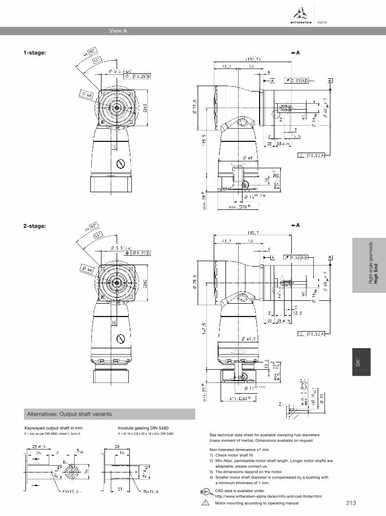
Non-tolerated dimensions ±1 mm1) Check motor shaft fit.2) Min./Max. permissible motor shaft length. Longer motor shafts are
adaptable, please contact us.3) The dimensions depend on the motor.4) Smaller motor shaft diameter is compensated by a bushing with
a minimum thickness of 1 mm.
See technical data sheet for available clamping hub diameters (mass moment of inertia). Dimensions available on request.
CAD data is available under http://www.wittenstein-alpha.de/en/info-and-cad-finder.html
Motor mounting according to operating manual !
Rig
ht-a
ngle
gea
rhea
dsH
igh
En
d
Alternatives: Output shaft variants
Keywayed output shaft in mmE = key as per DIN 6885, sheet 1, form A
Involute gearing DIN 5480 X = W 16 x 0,8 x 30 x 18 x 6m, DIN 5480
1-stage:
2-stage:
View A
213
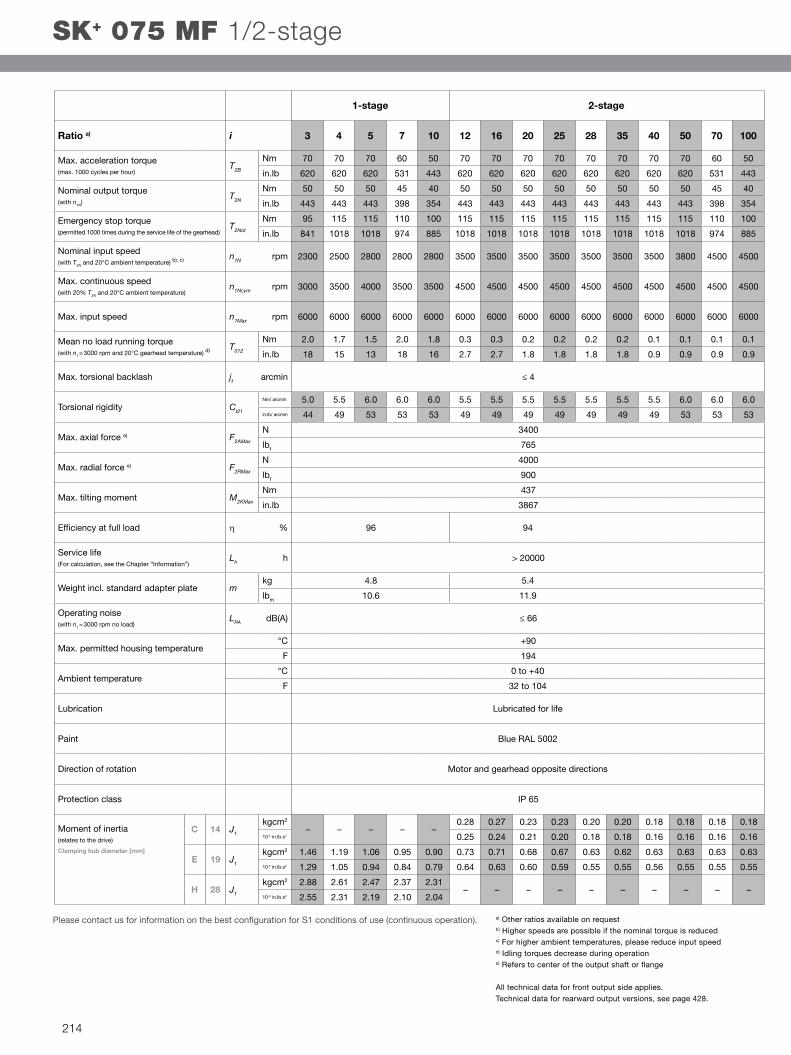
3 4 5 7 10 12 16 20 25 28 35 40 50 70 100
70 70 70 60 50 70 70 70 70 70 70 70 70 60 50
620 620 620 531 443 620 620 620 620 620 620 620 620 531 443
50 50 50 45 40 50 50 50 50 50 50 50 50 45 40
443 443 443 398 354 443 443 443 443 443 443 443 443 398 354
95 115 115 110 100 115 115 115 115 115 115 115 115 110 100
841 1018 1018 974 885 1018 1018 1018 1018 1018 1018 1018 1018 974 885
2300 2500 2800 2800 2800 3500 3500 3500 3500 3500 3500 3500 3800 4500 4500
3000 3500 4000 3500 3500 4500 4500 4500 4500 4500 4500 4500 4500 4500 4500
6000 6000 6000 6000 6000 6000 6000 6000 6000 6000 6000 6000 6000 6000 6000
2.0 1.7 1.5 2.0 1.8 0.3 0.3 0.2 0.2 0.2 0.2 0.1 0.1 0.1 0.1
18 15 13 18 16 2.7 2.7 1.8 1.8 1.8 1.8 0.9 0.9 0.9 0.9
≤ 4
5.0 5.5 6.0 6.0 6.0 5.5 5.5 5.5 5.5 5.5 5.5 5.5 6.0 6.0 6.0
44 49 53 53 53 49 49 49 49 49 49 49 53 53 53
3400
765
4000
900
437
3867
96 94
> 20000
4.8 5.4
10.6 11.9
≤ 66
+90
194
IP 65
– – – – –0.28 0.27 0.23 0.23 0.20 0.20 0.18 0.18 0.18 0.18
0.25 0.24 0.21 0.20 0.18 0.18 0.16 0.16 0.16 0.16
1.46 1.19 1.06 0.95 0.90 0.73 0.71 0.68 0.67 0.63 0.62 0.63 0.63 0.63 0.63
1.29 1.05 0.94 0.84 0.79 0.64 0.63 0.60 0.59 0.55 0.55 0.56 0.55 0.55 0.55
2.88 2.61 2.47 2.37 2.31– – – – – – – – – –
2.55 2.31 2.19 2.10 2.04
1-stage 2-stage
Ratio a) i
Max. acceleration torque(max. 1000 cycles per hour)
T2B Nm
in.lb
Nominal output torque(with n1N)
T2N Nm
in.lb
Emergency stop torque(permitted 1000 times during the service life of the gearhead)
T2Not Nm
in.lb
Nominal input speed(with T2N and 20°C ambient temperature) b), c) n1N rpm
Max. continuous speed(with 20% T2N and 20°C ambient temperature)
n1Ncym rpm
Max. input speed n1Max rpm
Mean no load running torque(with n1 = 3000 rpm and 20°C gearhead temperature) d) T012
Nm
in.lb
Max. torsional backlash jt arcmin
Torsional rigidity Ct21 Nm/ arcmin
in.lb/ arcmin
Max. axial force e) F2AMax N
lbf
Max. radial force e) F2RMax N
lbf
Max. tilting moment M2KMax
Nm
in.lb
Efficiency at full load η %
Service life(For calculation, see the Chapter “Information”)
Lh h
Weight incl. standard adapter plate mkg
lbm
Operating noise(with n1 = 3000 rpm no load)
LPA dB(A)
Max. permitted housing temperature°C
F
Ambient temperature°C 0 to +40
F 32 to 104
Lubrication Lubricated for life
Paint Blue RAL 5002
Direction of rotation Motor and gearhead opposite directions
Protection class
Moment of inertia(relates to the drive)
Clamping hub diameter [mm]
C 14 J1 kgcm2
10-3 in.lb.s2
E 19 J1
kgcm2
10-3 in.lb.s2
H 28 J1
kgcm2
10-3 in.lb.s2
a) Other ratios available on requestb) Higher speeds are possible if the nominal torque is reducedc) For higher ambient temperatures, please reduce input speedd) Idling torques decrease during operation e) Refers to center of the output shaft or flange
All technical data for front output side applies. Technical data for rearward output versions, see page 428.
SK+ 075 MF 1/2-stage
Please contact us for information on the best configuration for S1 conditions of use (continuous operation).
214

SK
+
alpha
A
A
Non-tolerated dimensions ±1 mm1) Check motor shaft fit.2) Min./Max. permissible motor shaft length. Longer motor shafts are
adaptable, please contact us.3) The dimensions depend on the motor.4) Smaller motor shaft diameter is compensated by a bushing with
a minimum thickness of 1 mm.
See technical data sheet for available clamping hub diameters (mass moment of inertia). Dimensions available on request.
CAD data is available under http://www.wittenstein-alpha.de/en/info-and-cad-finder.html
Motor mounting according to operating manual !
Rig
ht-a
ngle
gea
rhea
dsH
igh
En
d
Keywayed output shaft in mmE = key as per DIN 6885, sheet 1, form A
Involute gearing DIN 5480 in mmX = W 22 x 1.25 x 30 x 16 x 6m
1-stage:
2-stage:
Alternatives: Output shaft variants
View A
215

3 4 5 7 10 12 16 20 25 28 35 40 50 70 100
170 170 170 145 125 170 170 170 170 170 170 170 170 145 125
1505 1505 1505 1283 1106 1505 1505 1505 1505 1505 1505 1505 1505 1283 1106
100 100 100 90 80 100 100 100 100 100 100 100 100 90 80
885 885 885 797 708 885 885 885 885 885 885 885 885 797 708
220 260 260 255 250 260 260 260 260 260 260 260 260 255 250
1947 2301 2301 2257 2213 2301 2301 2301 2301 2301 2301 2301 2301 2257 2213
2200 2400 2700 2500 2500 3100 3100 3100 3100 3100 3100 3100 3500 4200 4200
3000 3400 3800 3400 3400 4000 4000 4000 4000 4000 4000 4000 4000 4200 4200
4500 4500 4500 4500 4500 4500 4500 4500 4500 4500 4500 4500 4500 4500 4500
3.8 3.0 2.3 3.5 2.8 0.6 0.6 0.5 0.4 0.4 0.3 0.2 0.2 0.2 0.2
34 27 20 31 25 5.3 5.3 4.4 3.5 3.5 2.7 1.8 1.8 1.8 1.8
≤ 4
10 11 13 13 13 11 11 11 11 11 11 11 13 13 13
89 97 115 115 115 97 97 97 97 97 97 97 115 115 115
5700
1283
6300
1418
833
7370
96 94
> 20000
9.3 10.0
21 22
≤ 66
+90
194
IP 65
– – – – –1.02 0.97 0.86 0.84 0.75 0.74 0.69 0.69 0.68 0.68
0.91 0.86 0.76 0.74 0.66 0.66 0.61 0.61 0.60 0.60
– – – – –2.59 2.54 2.42 2.40 2.31 2.30 2.26 2.25 2.25 2.25
2.29 2.25 2.14 2.13 2.05 2.04 2.00 1.99 1.99 1.99
4.64 3.80 3.34 2.98 2.79– – – – – – – – – –
4.10 3.36 2.95 2.64 2.47
11.9 11.0 10.6 10.2 10.0– – – – – – – – – –
10.5 9.77 9.37 9.05 8.89
1-stage 2-stage
Ratio a) i
Max. acceleration torque(max. 1000 cycles per hour)
T2B Nm
in.lb
Nominal output torque(with n1N)
T2N Nm
in.lb
Emergency stop torque(permitted 1000 times during the service life of the gearhead)
T2Not Nm
in.lb
Nominal input speed(with T2N and 20°C ambient temperature) b), c) n1N rpm
Max. continuous speed(with 20% T2N and 20°C ambient temperature)
n1Ncym rpm
Max. input speed n1Max rpm
Mean no load running torque(with n1 = 3000 rpm and 20°C gearhead temperature) d) T012
Nm
in.lb
Max. torsional backlash jt arcmin
Torsional rigidity Ct21 Nm/ arcmin
in.lb/ arcmin
Max. axial force e) F2AMax
N
lbf
Max. radial force e) F2RMax N
lbf
Max. tilting moment M2KMax
Nm
in.lb
Efficiency at full load η %
Service life(For calculation, see the Chapter “Information”)
Lh h
Weight incl. standardadapter plate m kg
lbm
Operating noise(with n1 = 3000 rpm no load)
LPA dB(A)
Max. permitted housing temperature°C
F
Ambient temperature°C 0 to +40
F 32 to 104
Lubrication Lubricated for life
Paint Blue RAL 5002
Direction of rotation Motor and gearhead opposite directions
Protection class
Moment of inertia(relates to the drive)
Clamping hub diameter [mm]
E 19 J1
kgcm2
10-3 in.lb.s2
G 24 J1
kgcm2
10-3 in.lb.s2
H 28 J1
kgcm2
10-3 in.lb.s2
K 38 J1
kgcm2
10-3 in.lb.s2
a) Other ratios available on requestb) Higher speeds are possible if the nominal torque is reducedc) For higher ambient temperatures, please reduce input speedd) Idling torques decrease during operation e) Refers to center of the output shaft or flange
All technical data for front output side applies. Technical data for rearward output versions, see page 428.
SK+ 100 MF 1/2-stage
Please contact us for information on the best configuration for S1 conditions of use (continuous operation).
216

SK
+
alpha
A
A
Non-tolerated dimensions ±1 mm1) Check motor shaft fit.2) Min./Max. permissible motor shaft length. Longer motor shafts are
adaptable, please contact us.3) The dimensions depend on the motor.4) Smaller motor shaft diameter is compensated by a bushing with
a minimum thickness of 1 mm.
See technical data sheet for available clamping hub diameters (mass moment of inertia). Dimensions available on request.
CAD data is available under http://www.wittenstein-alpha.de/en/info-and-cad-finder.html
Motor mounting according to operating manual !
Rig
ht-a
ngle
gea
rhea
dsH
igh
En
d
Keywayed output shaft in mmE = key as per DIN 6885, sheet 1, form A
Involute gearing DIN 5480 X = W 32 x 1.25 x 30 x 24 x 6m
1-stage:
2-stage:
Alternatives: Output shaft variants
View A
217

3 4 5 7 10 12 16 20 25 28 35 40 50 70 100
300 300 300 250 210 300 300 300 300 300 300 300 300 250 210
2655 2655 2655 2213 1859 2655 2655 2655 2655 2655 2655 2655 2655 2213 1859
190 190 190 175 160 190 190 190 190 190 190 190 190 175 160
1682 1682 1682 1549 1416 1682 1682 1682 1682 1682 1682 1682 1682 1549 1419
400 500 500 450 400 500 500 500 500 500 500 500 500 450 400
3540 4425 4425 3983 3540 4425 4425 4425 4425 4425 4425 4425 4425 3983 3540
1900 2000 2200 2000 2000 2900 2900 2900 2900 2900 2900 2900 3200 3200 3900
2500 2800 3100 2800 2800 4000 4000 4000 4000 4000 4000 4000 4200 4200 4200
4500 4500 4500 4500 4500 4500 4500 4500 4500 4500 4500 4500 4500 4500 4500
7.0 5.2 4.5 7.5 5.5 1.4 0.9 0.7 0.5 0.5 0.4 0.4 0.3 0.3 0.3
62 46 40 66 49 12.4 8 6.2 4.4 4.4 3.5 3.5 2.7 2.7 2.7
≤ 4
27 30 32 32 32 29 29 29 29 29 29 29 31 31 31
239 266 283 283 283 257 257 257 257 257 257 257 274 274 274
9900
2228
9500
2138
1692
14974
96 94
> 20000
22.6 25.0
50 55
≤ 68
+90
194
IP 65
– – – – –4.21 3.85 3.28 3.17 2.78 2.73 2.48 2.46 2.43 2.42
3.73 3.41 2.90 2.80 2.46 2.41 2.20 2.17 2.15 2.14
25.0 19.1 16.3 14.1 12.8 11.1 10.7 10.2 10.1 9.69 9.64 9.39 9.37 9.34 9.33
22.1 16.9 14.4 12.4 11.3 9.83 9.51 9.01 8.92 8.58 8.53 8.31 8.29 8.27 8.26
1-stage 2-stage
Ratio a) i
Max. acceleration torque(max. 1000 cycles per hour)
T2B
Nm
in.lb
Nominal output torque(with n1N)
T2N
Nm
in.lb
Emergency stop torque(permitted 1000 times during the service life of the gearhead)
T2Not
Nm
in.lb
Nominal input speed(with T2N and 20°C ambient temperature) b), c) n1N rpm
Max. continuous speed(with 20% T2N and 20°C ambient temperature)
n1Ncym rpm
Max. input speed n1Max rpm
Mean no load running torque(with n1 = 3000 rpm and 20°C gearhead temperature) d) T012
Nm
in.lb
Max. torsional backlash jt arcmin
Torsional rigidity Ct21 Nm/ arcmin
in.lb/ arcmin
Max. axial force e) F2AMax
N
lbf
Max. radial force e) F2RMax
N
lbf
Max. tilting moment M2KMax
Nm
in.lb
Efficiency at full load η %
Service life(For calculation, see the Chapter “Information”)
Lh h
Weight incl. standardadapter plate mkg
lbm
Operating noise(with n1 = 3000 rpm without load)
LPA dB(A)
Max. permitted housing temperature°C
F
Ambient temperature°C 0 to +40
F 32 to 104
Lubrication Lubricated for life
Paint Blue RAL 5002
Direction of rotation Motor and gearhead opposite directions
Protection class
Moment of inertia(relates to the drive)
Clamping hub diameter [mm]
G 24 J1
kgcm2
10-3 in.lb.s2
K 38 J1
kgcm2
10-3 in.lb.s2
a) Other ratios available on requestb) Higher speeds are possible if the nominal torque is reducedc) For higher ambient temperatures, please reduce input speedd) Idling torques decrease during operation e) Refers to center of the output shaft or flange
All technical data for front output side applies. Technical data for rearward output versions, see page 428.
Please contact us for information on the best configuration for S1 conditions of use (continuous operation).
SK+ 140 MF 1/2-stage
218

SK
+
alpha
A
A
Non-tolerated dimensions ±1 mm1) Check motor shaft fit.2) Min./Max. permissible motor shaft length. Longer motor shafts are
adaptable, please contact us.3) The dimensions depend on the motor.4) Smaller motor shaft diameter is compensated by a bushing with
a minimum thickness of 1 mm.
See technical data sheet for available clamping hub diameters (mass moment of inertia). Dimensions available on request.
CAD data is available under http://www.wittenstein-alpha.de/en/info-and-cad-finder.html
Motor mounting according to operating manual !
Rig
ht-a
ngle
gea
rhea
dsH
igh
En
d
Keywayed output shaft in mmE = key as per DIN 6885, sheet 1, form A
Involute gearing DIN 5480 X = W 40 x 2 x 30 x 18 x 6m
1-stage:
2-stage:
Alternatives: Output shaft variants
View A
219

3 4 5 7 10 12 16 20 25 28 35 40 50 70 100
640 640 640 550 470 640 640 640 640 640 640 640 640 550 470
5664 5664 5664 4868 4160 5664 5664 5664 5664 5664 5664 5664 5664 4868 4160
400 400 400 380 360 400 400 400 400 400 400 400 400 380 360
3540 3540 3540 3363 3186 3540 3540 3540 3540 3540 3540 3540 3540 3363 3186
900 1050 1050 970 900 1050 1050 1050 1050 1050 1050 1050 1050 970 900
7965 9293 9293 8585 7965 9293 9293 9293 9293 9293 9293 9293 9293 8585 7965
1600 1800 2000 1800 1800 2700 2700 2700 2700 2700 2700 2700 2900 3200 3400
2000 2400 2800 2500 2500 3500 3500 3500 3500 3500 3500 3500 3500 3800 3800
4000 4000 4000 4000 4000 4000 4000 4000 4000 4000 4000 4000 4000 4000 4000
14.5 12.0 10.0 15.0 12.5 3.0 2.3 1.8 1.6 1.3 1.2 0.9 0.9 0.9 0.9
128 106 89 133 111 26.6 20.4 15.9 14.2 11.5 10.6 8.0 8.0 8.0 8.0
≤ 4
64 71 79 78 77 71 71 71 71 71 71 71 78 78 78
566 628 699 690 681 628 628 628 628 628 628 628 690 690 690
14200
3195
14700
3308
3213
28435
96 94
> 20000
45.4 48
100 106
≤ 68
+90
194
IP 65
– – – – –15.3 14.0 12.3 12.0 10.9 10.7 10.1 10.0 9.95 9.91
13.6 12.3 10.9 10.6 9.65 9.48 8.96 8.88 8.81 8.77
73.3 51.6 42.1 34.0 29.7 30.0 28.7 27.1 26.7 25.6 25.4 24.8 24.7 24.7 24.6
64.9 45.6 37.3 30.1 26.3 26.6 25.4 23.9 23.6 22.7 22.5 22.0 21.9 21.8 21.8
1-stage 2-stage
Ratio a) i
Max. acceleration torque(max. 1000 cycles per hour)
T2B
Nm
in.lb
Nominal output torque(with n1N)
T2N Nm
in.lb
Emergency stop torque(permitted 1000 times during the service life of the gearhead)
T2Not
Nm
in.lb
Nominal input speed(with T2N and 20°C ambient temperature) b), c) n1N rpm
Max. continuous speed(with 20% T2N and 20°C ambient temperature)
n1Ncym rpm
Max. input speed n1Max rpm
Mean no load running torque(with n1 = 3000 rpm and 20°C gearhead temperature) d) T012
Nm
in.lb
Max. torsional backlash jt arcmin
Torsional rigidity Ct21 Nm/ arcmin
in.lb/ arcmin
Max. axial force e) F2AMax N
lbf
Max. radial force e) F2RMax N
lbf
Max. tilting moment M2KMax Nm
in.lb
Efficiency at full load η %
Service life(For calculation, see the Chapter “Information”)
Lh h
Weight incl. standardadapter plate mkg
lbm
Operating noise(with n1 = 3000 rpm no load)
LPA dB(A)
Max. permitted housing temperature°C
F
Ambient temperature°C 0 to +40
F 32 to 104
Lubrication Lubricated for life
Paint Blue RAL 5002
Direction of rotation Motor and gearhead opposite directions
Protection class
Moment of inertia(relates to the drive)
Clamping hub diameter [mm]
K 38 J1
kgcm2
10-3 in.lb.s2
M 48 J1
kgcm2
10-3 in.lb.s2
a) Other ratios available on requestb) Higher speeds are possible if the nominal torque is reducedc) For higher ambient temperatures, please reduce input speedd) Idling torques decrease during operation e) Refers to center of the output shaft or flange
All technical data for front output side applies. Technical data for rearward output versions, see page 428.
Please contact us for information on the best configuration for S1 conditions of use (continuous operation).
SK+ 180 MF 1/2-stage
220

SK
+
alpha
A
A
Non-tolerated dimensions ±1 mm1) Check motor shaft fit.2) Min./Max. permissible motor shaft length. Longer motor shafts are
adaptable, please contact us.3) The dimensions depend on the motor.4) Smaller motor shaft diameter is compensated by a bushing with
a minimum thickness of 1 mm.
See technical data sheet for available clamping hub diameters (mass moment of inertia). Dimensions available on request.
CAD data is available under http://www.wittenstein-alpha.de/en/info-and-cad-finder.html
Motor mounting according to operating manual !
Rig
ht-a
ngle
gea
rhea
dsH
igh
En
d
Keywayed output shaft in mmE = key as per DIN 6885, sheet 1, form A
Involute gearing DIN 5480 X = W 55 x 2 x 30 x 26 x 6m
1-stage:
2-stage:
Alternatives: Output shaft variants
View A
221

12 16 20 25 28 35 40 50 70 100
110 110 110 110 110 110 80 100 110 90
974 974 974 974 974 974 974 885 974 797
75 75 75 75 75 75 60 75 75 52
664 664 664 664 664 664 531 664 664 460
160 160 200 200 250 175 120 150 210 200
1416 1416 1770 1770 2213 1549 1062 1328 1859 1770
2000 2400 2400 2700 2400 2500 2500 2500 2500 2500
3000 3400 3400 3800 3400 3200 3200 3200 3200 3200
6000 6000 6000 6000 6000 6000 6000 6000 6000 6000
1.5 1.3 1.2 1.2 1.2 1.3 1.3 1.3 1.3 1.3
13.3 11.5 10.6 10.6 10.6 11.5 11.5 11.5 11.5 11.5
10
89
3350
753
4000
900
236
2089
94
> 20000
5.2
11.5
≤ 66
+90
194
IP 65
0.54 0.45 0.44 0.40 0.44 0.36 0.35 0.34 0.34 0.34
0.48 0.40 0.39 0.35 0.39 0.32 0.31 0.30 0.30 0.30
0.89 0.80 0.79 0.75 0.79 0.71 0.70 0.70 0.70 0.69
0.79 0.71 0.70 0.66 0.70 0.63 0.62 0.62 0.62 0.61
2-stage
Ratio a) i
Max. acceleration torque(max. 1000 cycles per hour)
T2B
Nm
in.lb
Nominal output torque(with n1N)
T2N
Nm
in.lb
Emergency stop torque(permitted 1000 times during the service life of the gearhead)
T2Not
Nm
in.lb
Nominal input speed(with T2N and 20°C ambient temperature) b), c) n1N rpm
Max. continuous speed(with 20% T2N and 20°C ambient temperature)
n1Ncym rpm
Max. input speed n1Max rpm
Mean no load running torque(with n1 = 3000 rpm and 20°C gearhead temperature) d) T012
Nm
in.lb
Max. torsional backlash jt arcmin Standard ≤ 5 / Reduced ≤ 3
Torsional rigidity Ct21 Nm/ arcmin
in.lb/ arcmin
Max. axial force e) F2AMax N
lbf
Max. radial force e) F2RMax N
lbf
Max. tilting moment M2KMax Nm
in.lb
Efficiency at full load η %
Service life(For calculation, see the Chapter “Information”)
Lh h
Weight incl. standard adapter plate mkg
lbm
Operating noise(with n1 = 3000 rpm no load)
LPA dB(A)
Max. permitted housing temperature°C
F
Ambient temperature°C 0 to +40
F 32 to 104
Lubrication Lubricated for life
Paint Blue RAL 5002
Direction of rotation Motor and gearhead opposite directions
Protection class
Moment of inertia(relates to the drive)
Clamping hub diameter [mm]
C 14 J1
kgcm2
10-3 in.lb.s2
E 19 J1
kgcm2
10-3 in.lb.s2
a) Other ratios up to i=1000 available on requestb) Higher speeds are possible if the nominal torque is reducedc) For higher ambient temperatures, please reduce input speedd) Idling torques decrease during operation e) Refers to center of the output shaft or flange
All technical data for front output side applies. Technical data for rearward output versions, see page 428.
Please contact us for information on the best configuration for S1 conditions of use (continuous operation).
SPK+ 075 MF 2-stage
222
alpha
SP
K+
A
Non-tolerated dimensions ±1 mm1) Check motor shaft fit.2) Min./Max. permissible motor shaft length. Longer
motor shafts are adaptable, please contact us.3) The dimensions depend on the motor.4) Smaller motor shaft diameter is compensated by a
bushing with a minimum thickness of 1 mm.
See technical data sheet for available clamping hub diameters (mass moment of inertia). Dimensions available on request.
CAD data is available under http://www.wittenstein-alpha.de/en/info-and-cad-finder.html
Motor mounting according to operating manual !
Rig
ht-a
ngle
gea
rhea
dsH
igh
En
d
2-stage:
Alternatives: Output shaft variants
View A
Keywayed output shaft in mmE = key as per DIN 6885, sheet 1, form A
Involute gearing DIN 5480 in mmX = W 22 x 1.25 x 30 x 16 x 6m, DIN 5480
Shaft mounted Mounted via shrink disc
223

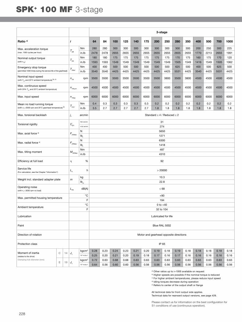
64 84 100 125 140 175 200 250 280 350 400 500 700 1000
110 110 110 110 110 110 110 110 110 110 80 100 110 90
974 974 974 974 974 974 974 974 974 974 708 885 974 797
75 75 75 75 75 75 75 75 75 75 60 75 75 52
664 664 664 664 664 664 664 664 664 664 531 664 664 460
160 160 200 200 200 200 200 200 250 175 120 150 210 200
1416 1416 1770 1770 1770 1770 1770 1770 2213 1549 1062 1328 1859 1770
4400 4400 4400 4400 4400 4400 4400 4800 4400 4800 5500 5500 5500 5500
5000 5000 5000 5000 5000 5000 5000 5000 5000 5000 5500 5500 5500 5500
6000 6000 6000 6000 6000 6000 6000 6000 6000 6000 6000 6000 6000 6000
0.3 0.3 0.3 0.3 0.3 0.3 0.2 0.2 0.2 0.2 0.2 0.2 0.2 0.2
2.7 2.7 2.7 2.7 2.7 2.7 1.8 1.8 1.8 1.8 1.8 1.8 1.8 1.8
10
89
3350
754
4000
900
236
2089
92
> 20000
5.5
12.2
≤ 66
+90
194
IP 65
0.09 0.07 0.08 0.07 0.06 0.06 0.06 0.06 0.06 0.06 0.06 0.06 0.06 0.06
0.08 0.06 0.07 0.06 0.05 0.05 0.05 0.05 0.05 0.05 0.05 0.05 0.05 0.05
0.20 0.18 0.19 0.19 0.18 0.18 0.17 0.17 0.17 0.17 0.17 0.17 0.17 0.17
0.18 0.16 0.17 0.17 0.16 0.16 0.15 0.15 0.15 0.15 0.15 0.15 0.15 0.15
3-stage
Ratio a) i
Max. acceleration torque(max. 1000 cycles per hour)
T2B
Nm
in.lb
Nominal output torque(with n1N)
T2N
Nm
in.lb
Emergency stop torque(permitted 1000 times during the service life of the gearhead)
T2Not
Nm
in.lb
Nominal input speed(with T2N and 20°C ambient temperature) b), c) n1N rpm
Max. continuous speed(with 20% T2N and 20°C ambient temperature)
n1Ncym rpm
Max. input speed n1Max rpm
Mean no load running torque(with n1 = 3000 rpm and 20°C gearhead temperature) d) T012
Nm
in.lb
Max. torsional backlash jt arcmin Standard ≤ 5 / Reduced ≤ 3
Torsional rigidity Ct21 Nm/ arcmin
in.lb/ arcmin
Max. axial force e) F2AMax N
lbf
Max. radial force e) F2RMax N
lbf
Max. tilting moment M2KMax Nm
in.lb
Efficiency at full load η %
Service life(For calculation, see the Chapter “Information”)
Lh h
Weight incl. standard adapter plate mkg
lbm
Operating noise(with n1 = 3000 rpm no load)
LPA dB(A)
Max. permitted housing temperature°C
F
Ambient temperature°C 0 to +40
F 32 to 104
Lubrication Lubricated for life
Paint Blue RAL 5002
Direction of rotation Motor and gearhead opposite directions
Protection class
Moment of inertia(relates to the drive)
Clamping hub diameter [mm]
B 11 J1
kgcm2
10-3 in.lb.s2
C 14 J1
kgcm2
10-3 in.lb.s2
a) Other ratios up to i=1000 available on requestb) Higher speeds are possible if the nominal torque is reducedc) For higher ambient temperatures, please reduce input speedd) Idling torques decrease during operation e) Refers to center of the output shaft or flange
All technical data for front output side applies. Technical data for rearward output versions, see page 428.
Please contact us for information on the best configuration for S1 conditions of use (continuous operation).
SPK+ 075 MF 3-stage
224

alpha
SP
K+
A
Non-tolerated dimensions ±1 mm1) Check motor shaft fit.2) Min./Max. permissible motor shaft length. Longer
motor shafts are adaptable, please contact us.3) The dimensions depend on the motor.4) Smaller motor shaft diameter is compensated by a
bushing with a minimum thickness of 1 mm.
See technical data sheet for available clamping hub diameters (mass moment of inertia). Dimensions available on request.
CAD data is available under http://www.wittenstein-alpha.de/en/info-and-cad-finder.html
Motor mounting according to operating manual !
Rig
ht-a
ngle
gea
rhea
dsH
igh
En
d
3-stage:
View A
Alternatives: Output shaft variants
Keywayed output shaft in mmE = key as per DIN 6885, sheet 1, form A
Involute gearing DIN 5480 in mmX = W 22 x 1.25 x 30 x 16 x 6m, DIN 5480
Shaft mounted Mounted via shrink disc
225

12 16 20 25 28 35 40 50 70 100
280 280 300 300 300 300 200 250 300 225
2478 2478 2655 2655 2655 2655 1770 2213 2655 1991
180 180 175 175 170 175 160 175 170 120
1593 1593 1549 1549 1505 1549 1416 1549 1505 1062
400 400 500 500 625 500 400 500 625 500
3540 3540 4425 4425 5531 4425 3540 4425 5531 4425
2000 2400 2400 2700 2400 2500 2500 2500 2500 2500
3000 3400 3400 3800 3400 3200 3200 3200 3200 3200
6000 6000 6000 6000 6000 6000 6000 6000 6000 6000
2.5 2.1 2.0 1.8 2.0 2.2 2.0 2.0 2.0 2.0
22.1 18.6 17.7 15.9 17.7 19.5 17.7 17.7 17.7 17.7
31
274
5650
1271
6300
1418
487
4310
94
> 20000
9.7
21.4
≤ 68
+90
194
IP 65
1.48 1.20 1.17 1.05 1.15 0.95 0.90 0.89 0.89 0.89
1.31 1.06 1.04 0.93 1.02 0.84 0.79 0.79 0.79 0.78
2.89 2.62 2.59 2.46 2.56 2.36 2.31 2.31 2.30 2.30
2.56 2.31 2.29 2.18 2.27 2.09 2.05 2.04 2.04 2.04
2-stage
Ratio a) i
Max. acceleration torque(max. 1000 cycles per hour)
T2B
Nm
in.lb
Nominal output torque(with n1N)
T2N Nm
in.lb
Emergency stop torque(permitted 1000 times during the service life of the gearhead)
T2Not Nm
in.lb
Nominal input speed(with T2N and 20°C ambient temperature) b), c) n1N rpm
Max. continuous speed(with 20% T2N and 20°C ambient temperature)
n1Ncym rpm
Max. input speed n1Max rpm
Mean no load running torque(with n1 = 3000 rpm and 20°C gearhead temperature) d) T012
Nm
in.lb
Max. torsional backlash jt arcmin Standard ≤ 4 / Reduced ≤ 2
Torsional rigidity Ct21 Nm/ arcmin
in.lb/ arcmin
Max. axial force e) F2AMax N
lbf
Max. radial force e) F2RMax N
lbf
Max. tilting moment M2KMax Nm
in.lb
Efficiency at full load η %
Service life(For calculation, see the Chapter “Information”)
Lh h
Weight incl. standard adapter plate m kg
lbm
Operating noise(with n1 = 3000 rpm no load)
LPA dB(A)
Max. permitted housing temperature°C
F
Ambient temperature°C 0 to +40
F 32 to 104
Lubrication Lubricated for life
Paint Blue RAL 5002
Direction of rotation Motor and gearhead opposite directions
Protection class
Moment of inertia(relates to the drive)
Clamping hub diameter [mm]
E 19 J1 kgcm2
10-3 in.lb.s2
H 28 J1 kgcm2
10-3 in.lb.s2
a) Other ratios up to i=1000 available on requestb) Higher speeds are possible if the nominal torque is reducedc) For higher ambient temperatures, please reduce input speedd) Idling torques decrease during operation e) Refers to center of the output shaft or flange
All technical data for front output side applies. Technical data for rearward output versions, see page 428.
Please contact us for information on the best configuration for S1 conditions of use (continuous operation).
SPK+ 100 MF 2-stage
226

alpha
SP
K+
A
Non-tolerated dimensions ±1 mm1) Check motor shaft fit.2) Min./Max. permissible motor shaft length. Longer
motor shafts are adaptable, please contact us.3) The dimensions depend on the motor.4) Smaller motor shaft diameter is compensated by a
bushing with a minimum thickness of 1 mm.
See technical data sheet for available clamping hub diameters (mass moment of inertia). Dimensions available on request.
CAD data is available under http://www.wittenstein-alpha.de/en/info-and-cad-finder.html
Motor mounting according to operating manual !
Rig
ht-a
ngle
gea
rhea
dsH
igh
En
d
2-stage:
View A
Alternatives: Output shaft variants
Keywayed output shaft in mmE = key as per DIN 6885, sheet 1, form A
Involute gearing DIN 5480 in mmX = W 32 x 1.25 x 30 x 24 x 6m, DIN 5480
Shaft mounted Mounted via shrink disc
227
64 84 100 125 140 175 200 250 280 350 400 500 700 1000
280 280 300 300 300 300 300 300 300 300 200 250 300 225
2478 2478 2655 2655 2655 2655 2655 2655 2655 2655 1770 2213 2655 1991
180 180 175 175 175 175 175 175 170 175 160 175 170 120
1593 1593 1549 1549 1549 1549 1549 1549 1505 1549 1416 1549 1505 1062
400 400 500 500 500 500 500 500 625 500 400 500 625 500
3540 3540 4425 4425 4425 4425 4425 4425 5531 4425 3540 4425 5531 4425
3500 3500 3500 3500 3500 3500 3500 3800 3500 3800 4500 4500 4500 4500
4500 4500 4500 4500 4500 4500 4500 4500 4500 4500 4500 4500 4500 4500
6000 6000 6000 6000 6000 6000 6000 6000 6000 6000 6000 6000 6000 6000
0.4 0.3 0.3 0.3 0.3 0.3 0.2 0.2 0.2 0.2 0.2 0.2 0.2 0.2
3.5 2.7 2.7 2.7 2.7 2.7 1.8 1.8 1.8 1.8 1.8 1.8 1.8 1.8
31
274
5650
1271
6300
1418
487
4310
92
> 20000
10.3
22.8
≤ 68
+90
194
IP 65
0.28 0.23 0.24 0.23 0.21 0.20 0.19 0.18 0.19 0.18 0.18 0.18 0.18 0.18
0.25 0.20 0.21 0.20 0.19 0.18 0.17 0.16 0.17 0.16 0.16 0.16 0.16 0.16
0.72 0.63 0.68 0.68 0.63 0.63 0.63 0.63 0.63 0.63 0.63 0.63 0.63 0.63
0.64 0.56 0.60 0.60 0.56 0.56 0.56 0.56 0.56 0.56 0.56 0.56 0.56 0.56
3-stage
Ratio a) i
Max. acceleration torque(max. 1000 cycles per hour)
T2B
Nm
in.lb
Nominal output torque(with n1N)
T2N Nm
in.lb
Emergency stop torque(permitted 1000 times during the service life of the gearhead)
T2Not Nm
in.lb
Nominal input speed(with T2N and 20°C ambient temperature) b), c) n1N rpm
Max. continuous speed(with 20% T2N and 20°C ambient temperature)
n1Ncym rpm
Max. input speed n1Max rpm
Mean no load running torque(with n1 = 3000 rpm and 20°C gearhead temperature) d) T012
Nm
in.lb
Max. torsional backlash jt arcmin Standard ≤ 4 / Reduced ≤ 2
Torsional rigidity Ct21 Nm/ arcmin
in.lb/ arcmin
Max. axial force e) F2AMax N
lbf
Max. radial force e) F2RMax N
lbf
Max. tilting moment M2KMax Nm
in.lb
Efficiency at full load η %
Service life(For calculation, see the Chapter “Information”)
Lh h
Weight incl. standard adapter plate m kg
lbm
Operating noise(with n1 = 3000 rpm no load)
LPA dB(A)
Max. permitted housing temperature°C
F
Ambient temperature°C 0 to +40
F 32 to 104
Lubrication Lubricated for life
Paint Blue RAL 5002
Direction of rotation Motor and gearhead opposite directions
Protection class
Moment of inertia(relates to the drive)
Clamping hub diameter [mm]
C 14 J1 kgcm2
10-3 in.lb.s2
E 19 J1 kgcm2
10-3 in.lb.s2
a) Other ratios up to i=1000 available on requestb) Higher speeds are possible if the nominal torque is reducedc) For higher ambient temperatures, please reduce input speedd) Idling torques decrease during operation e) Refers to center of the output shaft or flange
All technical data for front output side applies. Technical data for rearward output versions, see page 428.
Please contact us for information on the best configuration for S1 conditions of use (continuous operation).
SPK+ 100 MF 3-stage
228
alpha
SP
K+
A
Non-tolerated dimensions ±1 mm1) Check motor shaft fit.2) Min./Max. permissible motor shaft length. Longer
motor shafts are adaptable, please contact us.3) The dimensions depend on the motor.4) Smaller motor shaft diameter is compensated by a
bushing with a minimum thickness of 1 mm.
See technical data sheet for available clamping hub diameters (mass moment of inertia). Dimensions available on request.
CAD data is available under http://www.wittenstein-alpha.de/en/info-and-cad-finder.html
Motor mounting according to operating manual !
Rig
ht-a
ngle
gea
rhea
dsH
igh
En
d
3-stage:
View A
Alternatives: Output shaft variants
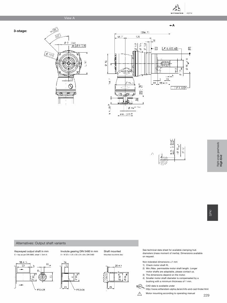
Keywayed output shaft in mmE = key as per DIN 6885, sheet 1, form A
Involute gearing DIN 5480 in mmX = W 32 x 1.25 x 30 x 24 x 6m, DIN 5480
Shaft mounted Mounted via shrink disc
229
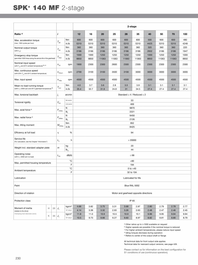
12 16 20 25 28 35 40 50 70 100
600 600 600 600 600 600 500 600 600 480
5310 5310 5310 5310 5310 5310 4425 5310 5310 4248
360 360 360 360 360 360 320 360 360 220
3186 3186 3186 3186 3186 3186 2832 3186 3186 1947
1000 1000 1250 1250 1250 1250 1000 1250 1250 1000
8850 8850 11063 11063 11063 11063 8850 11063 11063 8850
1900 2300 2300 2600 2300 2300 2300 2300 2300 2300
2700 3100 3100 3500 3100 3000 3000 3000 3000 3000
4500 4500 4500 4500 4500 4500 4500 4500 4500 4500
4.0 3.7 3.6 2.8 3.5 3.9 3.1 3.1 3.1 3.1
35.4 32.7 31.9 24.8 31 34.5 27.4 27.4 27.4 27.4
53
469
9870
2221
9450
2126
952
8425
94
> 20000
20
44
≤ 68
+90
194
IP 65
4.68 3.82 3.75 3.31 3.68 2.97 2.80 2.79 2.78 2.77
4.14 3.38 3.32 2.93 3.26 2.63 2.48 2.47 2.46 2.45
11.8 11.0 10.9 10.5 10.9 10.1 9.96 9.95 9.94 9.94
10.5 9.73 9.66 9.27 9.60 8.97 8.82 8.81 8.80 8.79
2-stage
Ratio a) i
Max. acceleration torque(max. 1000 cycles per hour)
T2B Nm
in.lb
Nominal output torque(with n1N)
T2N Nm
in.lb
Emergency stop torque(permitted 1000 times during the service life of the gearhead)
T2Not Nm
in.lb
Nominal input speed(with T2N and 20°C ambient temperature) b), c) n1N rpm
Max. continuous speed(with 20% T2N and 20°C ambient temperature)
n1Ncym rpm
Max. input speed n1Max rpm
Mean no load running torque(with n1 = 3000 rpm and 20°C gearhead temperature) d) T012
Nm
in.lb
Max. torsional backlash jt arcmin Standard ≤ 4 / Reduced ≤ 2
Torsional rigidity Ct21 Nm/ arcmin
in.lb/ arcmin
Max. axial force e) F2AMax
N
lbf
Max. radial force e) F2RMax
N
lbf
Max. tilting moment M2KMax
Nm
in.lb
Efficiency at full load η %
Service life(For calculation, see the Chapter “Information”)
Lh h
Weight incl. standard adapter plate mkg
lbm
Operating noise(with n1 = 3000 rpm no load)
LPA dB(A)
Max. permitted housing temperature°C
F
Ambient temperature°C 0 to +40
F 32 to 104
Lubrication Lubricated for life
Paint Blue RAL 5002
Direction of rotation Motor and gearhead opposite directions
Protection class
Moment of inertia(relates to the drive)
Clamping hub diameter [mm]
H 28 J1 kgcm2
10-3 in.lb.s2
K 38 J1 kgcm2
10-3 in.lb.s2
a) Other ratios up to i=1000 available on requestb) Higher speeds are possible if the nominal torque is reducedc) For higher ambient temperatures, please reduce input speedd) Idling torques decrease during operation e) Refers to center of the output shaft or flange
All technical data for front output side applies. Technical data for rearward output versions, see page 428.
Please contact us for information on the best configuration for S1 conditions of use (continuous operation).
SPK+ 140 MF 2-stage
230

alpha
SP
K+
A
Non-tolerated dimensions ±1 mm1) Check motor shaft fit.2) Min./Max. permissible motor shaft length. Longer
motor shafts are adaptable, please contact us.3) The dimensions depend on the motor.4) Smaller motor shaft diameter is compensated by a
bushing with a minimum thickness of 1 mm.
See technical data sheet for available clamping hub diameters (mass moment of inertia). Dimensions available on request.
CAD data is available under http://www.wittenstein-alpha.de/en/info-and-cad-finder.html
Motor mounting according to operating manual !
Rig
ht-a
ngle
gea
rhea
dsH
igh
En
d
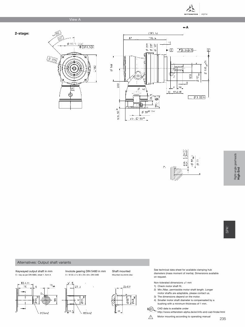
2-stage:
View A
Alternatives: Output shaft variants
Keywayed output shaft in mmE = key as per DIN 6885, sheet 1, form A
Involute gearing DIN 5480 in mmX = W 40 x 2 x 30 x 18 x 6m, DIN 5480
Shaft mounted Mounted via shrink disc
231

64 84 100 125 140 175 200 250 280 350 400 500 700 1000
600 600 600 600 600 600 600 600 600 600 500 600 600 480
5310 5310 5310 5310 5310 5310 5310 5310 5310 5310 4425 5310 5310 4248
360 360 360 360 360 360 360 360 360 360 320 360 360 220
3186 3186 3186 3186 3186 3186 3186 3186 3186 3186 2832 3186 3186 1947
1000 1000 1250 1250 1250 1250 1250 1250 1250 1250 1000 1250 1250 1000
8850 8850 11063 11063 11063 11063 11063 11063 11063 11063 8850 11063 11063 8850
3100 3100 3100 3100 3100 3100 3100 3500 3100 3500 4200 4200 4200 4200
4000 4000 4000 4000 4000 4000 4000 4000 4000 4000 4200 4200 4200 4200
4500 4500 4500 4500 4500 4500 4500 4500 4500 4500 4500 4500 4500 4500
0.7 0.4 0.6 0.5 0.5 0.4 0.3 0.3 0.3 0.3 0.3 0.3 0.3 0.3
6.2 3.5 5.3 4.4 4.4 3.5 2.7 2.7 2.7 2.7 2.7 2.7 2.7 2.7
53
469
9870
2221
9450
2126
952
8425
92
> 20000
20.7
45.7
< 68
+90
194
IP 65
1.01 0.76 0.88 0.85 0.76 0.75 0.70 0.69 0.70 0.69 0.69 0.69 0.69 0.69
0.89 0.67 0.78 0.75 0.67 0.66 0.62 0.61 0.62 0.61 0.61 0.61 0.61 0.61
2.57 2.32 2.44 2.42 2.32 2.31 2.26 2.25 2.26 2.25 2.25 2.25 2.25 2.25
2.27 2.05 2.16 2.14 2.05 2.04 2.00 1.99 2.00 1.99 1.99 1.99 1.99 1.99
3-stage
Ratio a) i
Max. acceleration torque(max. 1000 cycles per hour)
T2B Nm
in.lb
Nominal output torque(with n1N)
T2N Nm
in.lb
Emergency stop torque(permitted 1000 times during the service life of the gearhead)
T2Not Nm
in.lb
Nominal input speed(with T2N and 20°C ambient temperature) b), c) n1N rpm
Max. continuous speed(with 20% T2N and 20°C ambient temperature)
n1Ncym rpm
Max. input speed n1Max rpm
Mean no load running torque(with n1 = 3000 rpm and 20°C gearhead temperature) d) T012
Nm
in.lb
Max. torsional backlash jt arcmin Standard ≤ 4 / Reduced ≤ 2
Torsional rigidity Ct21 Nm/ arcmin
in.lb/ arcmin
Max. axial force e) F2AMax
N
lbf
Max. radial force e) F2RMax
N
lbf
Max. tilting moment M2KMax
Nm
in.lb
Efficiency at full load η %
Service life(For calculation, see the Chapter “Information”)
Lh h
Weight incl. standard adapter plate mkg
lbm
Operating noise(with n1 = 3000 rpm no load)
LPA dB(A)
Max. permitted housing temperature°C
F
Ambient temperature°C 0 to +40
F 32 to 104
Lubrication Lubricated for life
Paint Blue RAL 5002
Direction of rotation Motor and gearhead opposite directions
Protection class
Moment of inertia(relates to the drive)
Clamping hub diameter [mm]
E 19 J1 kgcm2
10-3 in.lb.s2
G 24 J1 kgcm2
10-3 in.lb.s2
a) Other ratios up to i=1000 available on requestb) Higher speeds are possible if the nominal torque is reducedc) For higher ambient temperatures, please reduce input speedd) Idling torques decrease during operation e) Refers to center of the output shaft or flange
All technical data for front output side applies. Technical data for rearward output versions, see page 428.
Please contact us for information on the best configuration for S1 conditions of use (continuous operation).
SPK+ 140 MF 3-stage
232

alpha
SP
K+
A
Non-tolerated dimensions ±1 mm1) Check motor shaft fit.2) Min./Max. permissible motor shaft length. Longer
motor shafts are adaptable, please contact us.3) The dimensions depend on the motor.4) Smaller motor shaft diameter is compensated by a
bushing with a minimum thickness of 1 mm.
See technical data sheet for available clamping hub diameters (mass moment of inertia). Dimensions available on request.
CAD data is available under http://www.wittenstein-alpha.de/en/info-and-cad-finder.html
Motor mounting according to operating manual !
Rig
ht-a
ngle
gea
rhea
dsH
igh
En
d
3-stage:
View A
Alternatives: Output shaft variants
Keywayed output shaft in mmE = key as per DIN 6885, sheet 1, form A
Involute gearing DIN 5480 in mmX = W 40 x 2 x 30 x 18 x 6m, DIN 5480
Shaft mounted Mounted via shrink disc
233

12 16 20 25 28 35 40 50 70 100
1100 1100 1100 1100 1100 1100 840 1050 1100 880
9735 9735 9735 9735 9735 9735 7434 9293 9735 7788
750 750 750 750 750 750 640 750 750 750
6638 6638 6638 6638 6638 6638 5664 6638 6638 6638
1600 1600 2000 2000 2750 2000 1600 2000 2750 2200
14160 14160 17700 17700 24338 17700 14160 17700 24338 19470
1600 1900 1900 2100 1900 2100 2100 2100 2100 2100
2300 2600 2600 2800 2600 3000 3000 3000 3000 3000
4500 4500 4500 4500 4500 4500 4500 4500 4500 4500
9.0 6.5 6.5 5.5 6.0 8.0 6.0 6.0 6.0 6.0
79.7 57.5 57.5 48.7 53.1 70.8 53.1 53.1 53.1 53.1
175
1549
14150
3184
14700
3308
1600
14160
94
> 20000
45
99
≤ 70
+90
194
IP 65
24.7 19.5 19.0 16.3 18.6 14.0 12.9 12.8 12.7 12.7
21.9 17.2 16.8 14.4 16.5 12.4 11.4 11.3 11.3 11.2
2-stage
Ratio a) i
Max. acceleration torque(max. 1000 cycles per hour)
T2B Nm
in.lb
Nominal output torque(with n1N)
T2N Nm
in.lb
Emergency stop torque(permitted 1000 times during the service life of the gearhead)
T2Not Nm
in.lb
Nominal input speed(with T2N and 20°C ambient temperature) b), c) n1N rpm
Max. continuous speed(with 20% T2N and 20°C ambient temperature)
n1Ncym rpm
Max. input speed n1Max rpm
Mean no load running torque(with n1 = 3000 rpm and 20°C gearhead temperature) d) T012
Nm
in.lb
Max. torsional backlash jt arcmin Standard ≤ 4 / Reduced ≤ 2
Torsional rigidity Ct21 Nm/ arcmin
in.lb/ arcmin
Max. axial force e) F2AMax N
lbf
Max. radial force e) F2RMax N
lbf
Max. tilting moment M2KMax Nm
in.lb
Efficiency at full load η %
Service life(For calculation, see the Chapter “Information”)
Lh h
Weight incl. standardadapter plate m kg
lbm
Operating noise(with n1 = 3000 rpm no load)
LPA dB(A)
Max. permitted housing temperature°C
F
Ambient temperature°C 0 to +40
F 32 to 104
Lubrication Lubricated for life
Paint Blue RAL 5002
Direction of rotation Motor and gearhead opposite directions
Protection class
Moment of inertia(relates to the drive)
Clamping hub diameter [mm]
K 38 J1
kgcm2
10-3 in.lb.s2
a) Other ratios up to i=1000 available on requestb) Higher speeds are possible if the nominal torque is reducedc) For higher ambient temperatures, please reduce input speedd) Idling torques decrease during operation e) Refers to center of the output shaft or flange
All technical data for front output side applies. Technical data for rearward output versions, see page 428.
Please contact us for information on the best configuration for S1 conditions of use (continuous operation).
SPK+ 180 MF 2-stage
234
alpha
SP
K+
A
Non-tolerated dimensions ±1 mm1) Check motor shaft fit.2) Min./Max. permissible motor shaft length. Longer
motor shafts are adaptable, please contact us.3) The dimensions depend on the motor.4) Smaller motor shaft diameter is compensated by a
bushing with a minimum thickness of 1 mm.
See technical data sheet for available clamping hub diameters (mass moment of inertia). Dimensions available on request.
CAD data is available under http://www.wittenstein-alpha.de/en/info-and-cad-finder.html
Motor mounting according to operating manual !
Rig
ht-a
ngle
gea
rhea
dsH
igh
En
d
2-stage:
View A
Alternatives: Output shaft variants
Keywayed output shaft in mmE = key as per DIN 6885, sheet 1, form A
Involute gearing DIN 5480 in mmX = W 55 x 2 x 30 x 26 x 6m, DIN 5480
Shaft mounted Mounted via shrink disc
235

64 84 100 125 140 175 200 250 280 350 400 500 700 1000
1100 1100 1100 1100 1100 1100 1100 1100 1100 1100 840 1050 1100 880
9735 9735 9735 9735 9735 9735 9735 9735 9735 9735 7434 9293 9735 7788
750 750 750 750 750 750 750 750 750 750 640 750 750 750
6638 6638 6638 6638 6638 6638 6638 6638 6638 6638 5664 6638 6638 6638
1600 1600 2000 2000 2000 2000 2000 2000 2750 2000 1600 2000 2750 2200
14160 14160 17700 17700 17700 17700 17700 17700 24338 17700 14160 17700 24338 19470
2900 2900 2900 2900 2900 2900 2900 3200 2900 3200 3900 3900 3900 3900
4000 4000 4000 4000 4000 4000 4000 4000 4000 4000 4200 4200 4200 4200
4500 4500 4500 4500 4500 4500 4500 4500 4500 4500 4500 4500 4500 4500
1 0.5 0.8 0.6 0.6 0.5 0.5 0.4 0.5 0.4 0.4 0.4 0.4 0.4
8.9 4.4 7.1 5.3 5.3 4.4 4.4 3.5 4.4 3.5 3.5 3.5 3.5 3.5
175
1549
14150
3184
14700
3308
1600
14160
92
> 20000
47.4
104.8
< 70
+90
194
IP 65
3.97 2.82 3.36 3.22 2.82 2.75 2.50 2.47 2.50 2.44 2.42 2.42 2.42 2.42
3.51 2.50 2.97 2.85 2.50 2.43 2.21 2.19 2.21 2.16 2.14 2.14 2.14 2.14
10.90 9.74 10.30 10.10 9.74 9.66 9.41 9.38 9.41 9.38 9.33 9.33 9.33 9.33
9.65 8.62 9.12 8.94 8.62 8.55 8.33 8.30 8.33 8.30 8.26 8.26 8.26 8.26
3-stage
Ratio a) i
Max. acceleration torque(max. 1000 cycles per hour)
T2B Nm
in.lb
Nominal output torque(with n1N)
T2N Nm
in.lb
Emergency stop torque(permitted 1000 times during the service life of the gearhead)
T2Not Nm
in.lb
Nominal input speed(with T2N and 20°C ambient temperature) b), c) n1N rpm
Max. continuous speed(with 20% T2N and 20°C ambient temperature)
n1Ncym rpm
Max. input speed n1Max rpm
Mean no load running torque(with n1 = 3000 rpm and 20°C gearhead temperature) d) T012
Nm
in.lb
Max. torsional backlash jt arcmin Standard ≤ 4 / Reduced ≤ 2
Torsional rigidity Ct21 Nm/ arcmin
in.lb/ arcmin
Max. axial force e) F2AMax N
lbf
Max. radial force e) F2RMax N
lbf
Max. tilting moment M2KMax Nm
in.lb
Efficiency at full load η %
Service life(For calculation, see the Chapter “Information”)
Lh h
Weight incl. standardadapter plate m kg
lbm
Operating noise(with n1 = 3000 rpm no load)
LPA dB(A)
Max. permitted housing temperature°C
F
Ambient temperature°C 0 to +40
F 32 to 104
Lubrication Lubricated for life
Paint Blue RAL 5002
Direction of rotation Motor and gearhead opposite directions
Protection class
Moment of inertia(relates to the drive)
Clamping hub diameter [mm]
G 24 J1
kgcm2
10-3 in.lb.s2
K 38 J1
kgcm2
10-3 in.lb.s2
a) Other ratios up to i=1000 available on requestb) Higher speeds are possible if the nominal torque is reducedc) For higher ambient temperatures, please reduce input speedd) Idling torques decrease during operation e) Refers to center of the output shaft or flange
All technical data for front output side applies. Technical data for rearward output versions, see page 428.
Please contact us for information on the best configuration for S1 conditions of use (continuous operation).
SPK+ 180 MF 3-stage
236

alpha
SP
K+
A
Non-tolerated dimensions ±1 mm1) Check motor shaft fit.2) Min./Max. permissible motor shaft length. Longer
motor shafts are adaptable, please contact us.3) The dimensions depend on the motor.4) Smaller motor shaft diameter is compensated by a
bushing with a minimum thickness of 1 mm.
See technical data sheet for available clamping hub diameters (mass moment of inertia). Dimensions available on request.
CAD data is available under http://www.wittenstein-alpha.de/en/info-and-cad-finder.html
Motor mounting according to operating manual !
Rig
ht-a
ngle
gea
rhea
dsH
igh
En
d
3-stage:
View A
Alternatives: Output shaft variants
Keywayed output shaft in mmE = key as per DIN 6885, sheet 1, form A
Involute gearing DIN 5480 in mmX = W 55 x 2 x 30 x 26 x 6m, DIN 5480
Shaft mounted Mounted via shrink disc
237

12 16 20 25 28 35 40 50 70 100
2500 2500 2500 2500 2400 2400 1850 2300 2400 1900
22125 22125 22125 22125 21240 21240 16373 20355 21240 16815
1500 1500 1500 1500 1400 1500 1400 1500 1400 1000
13.275 13275 13275 13275 12390 13275 12390 13275 12390 8850
3600 4200 5200 5200 5200 5200 3600 4500 5200 5000
31860 37170 46020 46020 46020 46020 31860 39825 46020 44250
1500 1700 1700 1900 1700 1900 1700 1700 1700 1700
1900 2300 2300 2700 2300 2700 2400 2400 2400 2400
4000 4000 4000 4000 4000 4000 4000 4000 4000 4000
18.5 17.0 15.0 13.0 14.0 12.0 15.0 15.0 14.0 13.0
163.7 150.5 132.8 115.1 123.9 106.2 132.8 132.8 123.9 115.1
300 300 300 300 300 300 300 300 300 300
2.655 2.655 2.655 2.655 2.655 2.655 2.655 2.655 2.655 2.655
30000
6750
21000
4725
3100
27435
94
> 20000
82
181
≤ 71
+90
194
IP 65
M 48
78.80 54.60 53.00 43.40 51.50 42.20 30.20 30.00 29.80 29.80
69.74 48.32 46.91 38.41 45.58 37.35 26.73 26.55 26.37 26.37
SPK+ 210 MF 2-stage
2-stage
Ratio a) i
Max. acceleration torque(max. 1000 cycles per hour)
T2B
Nm
in.lb
Nominal output torque(with n1N )
T2N
Nm
in.lb
Emergency stop torque(permitted 1000 times during the service life of the gearhead)
T2Not
Nm
in.lb
Nominal input speed(with T2N and 20°C ambient temperature) b), c) n1N rpm
Max. continuous speed(with 20 % T2N and 20°C ambient temperature)
n1Ncym rpm
Max. input speed n1Max rpm
Mean no load running torque(with n1 = 3000 rpm and 20°C gearhead temperature) d) T012
Nm
in.lb
Max. torsional backlash jt arcmin Standard ≤4 / Reduced ≤2
Torsional rigidity Ct21 Nm/ arcmin
in.lb/ arcmin
Max. axial force e) F2AMax
N
lbf
Max. radial force e) F2RMax
N
lbf
Max. tilting moment M2KMax
Nm
in.lb
Efficiency at full load η %
Service life(For calculation, see the Chapter “Information”)
Lh h
Weight incl. standard adapter plate mkg
lbm
Operating noise(with n1 = 3000 rpm no load)
LPA dB(A)
Max. permitted housing temperature°C
F
Ambient temperature °C 0 to +40
F 32 to 104
Lubrication Lubricated for life
Paint Blue RAL 5002
Direction of rotation Motor and gearhead opposite directions
Protection class
Moment of inertia(relates to the drive)
Clamping hub diameter [mm]J1
kgcm2
10-3 in.lb.s2
a) Other ratios available on requestb) Higher speeds are possible if the nominal torque is reducedc) For higher ambient temperatures, please reduce input speedd) Idling torques decrease during operation e) Refers to center of the output shaft or flange
All technical data for front output side applies. Technical data for rearward output versions, see page 428.
Please contact us for information on the best configuration for S1 conditions of use (continuous operation).
238

alpha
SP
K+
A
Non-tolerated dimensions ±1 mm1) Check motor shaft fit.2) Min./Max. permissible motor shaft length. Longer
motor shafts are adaptable, please contact us.3) The dimensions depend on the motor.4) Smaller motor shaft diameter is compensated by a
bushing with a minimum thickness of 1 mm.
See technical data sheet for available clamping hub diameters (mass moment of inertia). Dimensions available on request.
CAD data is available under http://www.wittenstein-alpha.de/en/info-and-cad-finder.html
Motor mounting according to operating manual !
Rig
ht-a
ngle
gea
rhea
dsH
igh
En
d
2-stage:
View A
Alternatives: Output shaft variants
Keywayed output shaft in mmE = key as per DIN 6885, sheet 1, form A
Involute gearing DIN 5480 in mmX = W 70 x 2 x 30 x 34 x 6m, DIN 5480
239

64 84 100 125 140 175 200 250 280 350 400 500 700 1000
2400 2400 2500 2500 2500 2500 2500 2500 2400 2400 1900 2350 2400 1900
21240 21240 22125 22125 22125 22125 22125 22125 21240 21240 16815 20798 21240 16815
1500 1500 1500 1500 1500 1500 1500 1500 1400 1400 1500 1500 1400 1000
13275 13275 13275 13275 13275 13275 13275 13275 12390 12390 13275 13275 12390 8850
4200 3600 5200 5200 5200 5200 5200 5200 5200 5200 3600 4500 5200 5000
37170 31860 46020 46020 46020 46020 46020 46020 46020 46020 31860 39825 46020 44250
2700 2700 2700 2700 2700 2700 2700 2900 2700 2900 3400 3400 3400 3400
3500 3500 3500 3500 3500 3500 3500 3500 3500 3500 3500 3500 3800 3800
4000 4000 4000 4000 4000 4000 4000 4000 4000 4000 4000 4000 4000 4000
2.4 1.2 1.9 1.7 1.3 1.3 1.0 1.0 1.0 1.0 1.0 1.0 1.0 1.0
21.2 10.6 16.8 15.0 11.5 11.5 8.9 8.9 8.9 8.9 8.9 8.9 8.9 8.9
300 300 300 300 300 300 300 300 300 300 300 300 300 300
2.655 2.655 2.655 2.655 2.655 2.655 2.655 2.655 2.655 2.655 2.655 2.655 2.655 2.655
30000
6750
21000
4725
3100
27435
92
> 20000
86
190
≤ 71
+90
194
IP 65
K 3814.00 10.90 12.30 12.00 10.90 10.70 10.10 10.00 10.10 10.00 9.90 9.90 9.90 9.90
12.39 9.65 10.89 10.62 9.65 9.47 8.94 8.85 8.94 8.85 8.76 8.76 8.76 8.76
M 4828.70 25.60 27.10 26.70 26.70 25.60 24.80 24.70 24.80 24.70 24.60 24.60 24.60 24.60
25.40 22.66 23.98 23.63 23.63 22.66 21.95 21.86 21.95 21.86 21.77 21.77 21.77 21.77
3-stage
Ratio a) i
Max. acceleration torque(max. 1000 cycles per hour)
T2B
Nm
in.lb
Nominal output torque(with n1N )
T2N
Nm
in.lb
Emergency stop torque(permitted 1000 times during the service life of the gearhead)
T2Not
Nm
in.lb
Nominal input speed(with T2N and 20°C ambient temperature) b), c) n1N rpm
Max. continuous speed(with 20 % T2N and 20°C ambient temperature)
n1Ncym rpm
Max. input speed n1Max rpm
Mean no load running torque(with n1 = 3000 rpm and 20°C gearhead temperature) d) T012
Nm
in.lb
Max. torsional backlash jt arcmin Standard ≤4 / Reduced ≤2
Torsional rigidity Ct21 Nm/ arcmin
in.lb/ arcmin
Max. axial force e) F2AMax
N
lbf
Max. radial force e) F2RMax
N
lbf
Max. tilting moment M2KMax
Nm
in.lb
Efficiency at full load η %
Service life(For calculation, see the Chapter “Information”)
Lh h
Weight incl. standard adapter plate mkg
lbm
Operating noise(with n1 = 3000 rpm no load)
LPA dB(A)
Max. permitted housing temperature°C
F
Ambient temperature °C 0 to +40
F 32 to 104
Lubrication Lubricated for life
Paint Blue RAL 5002
Direction of rotation Motor and gearhead opposite directions
Protection class
Moment of inertia(relates to the drive)
Clamping hub diameter [mm]
J1
kgcm2
10-3 in.lb.s2
J1
kgcm2
10-3 in.lb.s2
SPK+ 210 MF 3-stage
a) Other ratios available on requestb) Higher speeds are possible if the nominal torque is reducedc) For higher ambient temperatures, please reduce input speedd) Idling torques decrease during operation e) Refers to center of the output shaft or flange
All technical data for front output side applies. Technical data for rearward output versions, see page 428.
Please contact us for information on the best configuration for S1 conditions of use (continuous operation).
240

alpha
SP
K+
A
Non-tolerated dimensions ±1 mm1) Check motor shaft fit.2) Min./Max. permissible motor shaft length. Longer
motor shafts are adaptable, please contact us.3) The dimensions depend on the motor.4) Smaller motor shaft diameter is compensated by a
bushing with a minimum thickness of 1 mm.
See technical data sheet for available clamping hub diameters (mass moment of inertia). Dimensions available on request.
CAD data is available under http://www.wittenstein-alpha.de/en/info-and-cad-finder.html
Motor mounting according to operating manual !
Rig
ht-a
ngle
gea
rhea
dsH
igh
En
d
3-stage:
View A
Alternatives: Output shaft variants
Keywayed output shaft in mmE = key as per DIN 6885, sheet 1, form A
Involute gearing DIN 5480 in mmX = W 70 x 2 x 30 x 34 x 6m, DIN 5480
241

48 64 100 125 140 175 200 250 280 350 400 500 700 1000
4500 4500 4500 4500 4500 4500 4500 4500 4300 4500 4000 4300 4300 3400
39825 39825 39825 39825 39825 39825 39825 39825 38055 39825 35400 38055 38055 30090
2500 2500 2500 2500 2500 2500 2500 2500 2300 2500 2500 2500 2300 1700
22125 22125 22125 22125 22125 22125 22125 22125 20355 22125 22125 22125 20355 15045
6400 8000 8500 8500 8500 8500 8500 8500 8500 8500 8500 8500 8500 6800
56640 70800 75225 75225 75225 75225 75225 75225 75225 75225 75225 75225 75225 60180
1800 1900 1900 2100 1900 2100 2100 2100 2100 2100 2100 2100 2100 2100
2000 2200 2600 2600 2300 2300 2300 2300 2300 2300 2300 2300 2300 2300
4500 4500 4500 4500 4500 4500 4500 4500 4500 4500 4500 4500 4500 4500
11.0 8.0 7.0 7.0 8.0 8.0 7.0 6.0 6.0 6.0 6.0 6.0 6.0 6.0
94.3 70.8 62.0 62.0 70.8 70.8 62.0 53.1 53.1 53.1 53.1 53.1 53.1 53.1
510 510 510 510 510 510 510 510 510 510 510 510 510 510
4.514 4.514 4.514 4.514 4.514 4.514 4.514 4.514 4.514 4.514 4.514 4.514 4.514 4.514
33000
7425
30000
6750
5000
44250
92
> 20000
93
206
≤ 71
+90
194
IP 65
K 38
26.5 20.00 17.00 17.00 15.00 15.00 13.00 13.00 13.00 13.00 13.00 13.00 13.00 13.00
23.40 17.70 15.05 15.05 13.28 13.28 11.51 11.51 11.51 11.51 11.51 11.51 11.51 11.51
3-stage
Ratio a) i
Max. acceleration torque(max. 1000 cycles per hour)
T2B
Nm
in.lb
Nominal output torque(with n1N )
T2N
Nm
in.lb
Emergency stop torque(permitted 1000 times during the service life of the gearhead)
T2Not
Nm
in.lb
Nominal input speed(with T2N and 20°C ambient temperature) b), c) n1N rpm
Max. continuous speed(with 20 % T2N and 20°C ambient temperature)
n1Ncym rpm
Max. input speed n1Max rpm
Mean no load running torque(with n1 = 3000 rpm and 20°C gearhead temperature) d) T012
Nm
in.lb
Max. torsional backlash jt arcmin Standard ≤ 5,5 / Reduced ≤ 3,5
Torsional rigidity Ct21 Nm/ arcmin
in.lb/ arcmin
Max. axial force e) F2AMax
N
lbf
Max. radial force e) F2RMax
N
lbf
Max. tilting moment M2KMax
Nm
in.lb
Efficiency at full load η %
Service life(For calculation, see the Chapter “Information”)
Lh h
Weight incl. standard adapter plate mkg
lbm
Operating noise(with n1 = 3000 rpm no load)
LPA dB(A)
Max. permitted housing temperature°C
F
Ambient temperature °C 0 to +40
F 32 to 104
Lubrication Lubricated for life
Paint Blue RAL 5002
Direction of rotation Motor and gearhead opposite directions
Protection class
Moment of inertia(relates to the drive)
Clamping hub diameter [mm]J1
kgcm2
10-3 in.lb.s2
SPK+ 240 MF 3-stage
a) Other ratios available on requestb) Higher speeds are possible if the nominal torque is reducedc) For higher ambient temperatures, please reduce input speedd) Idling torques decrease during operation e) Refers to center of the output shaft or flange
All technical data for front output side applies. Technical data for rearward output versions, see page 428.
Please contact us for information on the best configuration for S1 conditions of use (continuous operation).
242

alpha
SP
K+
A
Non-tolerated dimensions ±1 mm1) Check motor shaft fit.2) Min./Max. permissible motor shaft length. Longer
motor shafts are adaptable, please contact us.3) The dimensions depend on the motor.4) Smaller motor shaft diameter is compensated by a
bushing with a minimum thickness of 1 mm.
See technical data sheet for available clamping hub diameters (mass moment of inertia). Dimensions available on request.
CAD data is available under http://www.wittenstein-alpha.de/en/info-and-cad-finder.html
Motor mounting according to operating manual !
Rig
ht-a
ngle
gea
rhea
dsH
igh
En
d
3-stage:
View A
Alternatives: Output shaft variants
Keywayed output shaft in mmE = key as per DIN 6885, sheet 1, form A
Involute gearing DIN 5480 in mmX = W 80 x 2 x 30 x 38 x 6m, DIN 5480
243

144 192 256 300 375 420 500 560 600 700 800 875 1000
4500 4500 4500 4500 4500 4500 4500 4500 4500 4500 4500 4500 4500
39825 39825 39825 39825 39825 39825 39825 39825 39825 39825 39825 39825 39825
2500 2500 2500 2500 2500 2500 2500 2500 2500 2500 2500 2500 2500
22125 22125 22125 22125 22125 22125 22125 22125 22125 22125 22125 22125 22125
8000 8000 8000 8500 8500 8500 8500 8500 8500 8500 8500 8500 8500
70800 70800 70800 75225 75225 75225 75225 75225 75225 75225 75225 75225 75225
2700 2900 2900 2900 2900 2900 2900 2900 2900 2900 2900 2900 3200
3800 4000 4000 4000 4000 4000 4000 4000 4000 4000 4000 4000 4200
4500 4500 4500 4500 4500 4500 4500 4500 4500 4500 4500 4500 4500
3.2 2.3 1.6 1.3 0.7 0.9 0.9 0.8 0.7 0.7 0.6 0.6 0.5
28.3 20.4 14.2 11.5 6.2 8.0 8.0 7.1 6.2 6.2 5.3 5.3 4.4
510 510 510 510 510 510 510 510 510 510 510 510 510
4.514 4.514 4.514 4.514 4.514 4.514 4.514 4.514 4.514 4.514 4.514 4.514 4.514
33000
7425
30000
6750
5000
44250
90
> 20000
96
212
≤ 71
+90
194
IP 65
G 245.96 4.30 3.90 3.32 3.31 2.80 3.18 2.80 2.49 2.73 2.49 2.73 2.46
5.28 3.81 3.45 2.94 2.93 2.48 2.82 2.47 2.21 2.42 2.20 2.42 2.18
K 3812.87 11.19 10.81 10.23 10.22 9.72 10.09 9.71 9.40 9.65 9.40 9.65 9.37
11.39 9.91 9.57 9.05 9.05 8.60 8.93 8.59 8.32 8.54 8.32 8.54 8.29
4-stage
Ratio a) i
Max. acceleration torque(max. 1000 cycles per hour)
T2B
Nm
in.lb
Nominal output torque(with n1N )
T2N
Nm
in.lb
Emergency stop torque(permitted 1000 times during the service life of the gearhead)
T2Not
Nm
in.lb
Nominal input speed(with T2N and 20°C ambient temperature) b), c) n1N rpm
Max. continuous speed(with 20 % T2N and 20°C ambient temperature)
n1Ncym rpm
Max. input speed n1Max rpm
Mean no load running torque(with n1 = 3000 rpm and 20°C gearhead temperature) d) T012
Nm
in.lb
Max. torsional backlash jt arcmin Standard ≤ 5,5 / Reduced ≤ 3,5
Torsional rigidity Ct21 Nm/ arcmin
in.lb/ arcmin
Max. axial force e) F2AMax
N
lbf
Max. radial force e) F2RMax
N
lbf
Max. tilting moment M2KMax
Nm
in.lb
Efficiency at full load η %
Service life(For calculation, see the Chapter “Information”)
Lh h
Weight incl. standard adapter plate mkg
lbm
Operating noise(with n1 = 3000 rpm no load)
LPA dB(A)
Max. permitted housing temperature°C
F
Ambient temperature °C 0 to +40
F 32 to 104
Lubrication Lubricated for life
Paint Blue RAL 5002
Direction of rotation Motor and gearhead opposite directions
Protection class
Moment of inertia(relates to the drive)
Clamping hub diameter [mm]
J1 kgcm2
10-3 in.lb.s2
J1
kgcm2
10-3 in.lb.s2
SPK+ 240 MF 4-stage i=144-1000
a) Other ratios available on requestb) Higher speeds are possible if the nominal torque is reducedc) For higher ambient temperatures, please reduce input speedd) Idling torques decrease during operation e) Refers to center of the output shaft or flange
All technical data for front output side applies. Technical data for rearward output versions, see page 428.
Please contact us for information on the best configuration for S1 conditions of use (continuous operation).
244

alpha
SP
K+
A
Non-tolerated dimensions ±1 mm1) Check motor shaft fit.2) Min./Max. permissible motor shaft length. Longer
motor shafts are adaptable, please contact us.3) The dimensions depend on the motor.4) Smaller motor shaft diameter is compensated by a
bushing with a minimum thickness of 1 mm.
See technical data sheet for available clamping hub diameters (mass moment of inertia). Dimensions available on request.
CAD data is available under http://www.wittenstein-alpha.de/en/info-and-cad-finder.html
Motor mounting according to operating manual !
Rig
ht-a
ngle
gea
rhea
dsH
igh
En
d
4-stage:
View A
Alternatives: Output shaft variants
Keywayed output shaft in mmE = key as per DIN 6885, sheet 1, form A
Involute gearing DIN 5480 in mmX = W 80 x 2 x 30 x 38 x 6m, DIN 5480
245

1225 1400 1750 2000 2800 3500 5000 7000 10000
4500 4500 4500 4200 4300 4500 4300 4300 3400
39825 39825 39825 37170 38055 39825 38055 38055 30090
2500 2500 2500 2500 2300 2500 2500 2300 1700
22125 22125 22125 22125 20355 22125 22125 20355 15045
8500 8500 8500 8000 8500 8500 8500 8500 6800
75225 75225 75225 70800 75225 75225 75225 75225 60180
2900 2900 3200 3900 3900 3900 3900 3900 3900
4000 4000 4200 4200 4200 4200 4200 4200 4200
4500 4500 4500 4500 4500 4500 4500 4500 4500
0.6 0.6 0.4 0.4 0.4 0.4 0.4 0.3 0.3
5.3 5.3 3.5 3.5 3.5 3.5 3.5 2.7 2.7
510 510 510 510 510 510 510 510 510
4.514 4.514 4.514 4.514 4.514 4.514 4.514 4.514 4.514
33000
7425
30000
6750
5000
44250
90
> 20000
96
212
≤ 71
+90
194
IP 65
G 242.73 2.49 2.46 2.42 2.42 2.42 2.42 2.42 2.42
2.42 2.20 2.17 2.14 2.14 2.14 2.14 2.14 2.14
K 389.64 9.40 9.37 9.33 9.33 9.33 9.33 9.33 9.33
8.53 8.32 8.29 8.26 8.26 8.26 8.26 8.26 8.26
4-stage
Ratio a) i
Max. acceleration torque(max. 1000 cycles per hour)
T2B
Nm
in.lb
Nominal output torque(with n1N )
T2N
Nm
in.lb
Emergency stop torque(permitted 1000 times during the service life of the gearhead)
T2Not
Nm
in.lb
Nominal input speed(with T2N and 20°C ambient temperature) b), c) n1N rpm
Max. continuous speed(with 20 % T2N and 20°C ambient temperature)
n1Ncym rpm
Max. input speed n1Max rpm
Mean no load running torque(with n1 = 3000 rpm and 20°C gearhead temperature) d) T012
Nm
in.lb
Max. torsional backlash jt arcmin Standard ≤ 5,5 / Reduced ≤ 3,5
Torsional rigidity Ct21 Nm/ arcmin
in.lb/ arcmin
Max. axial force e) F2AMax
N
lbf
Max. radial force e) F2RMax
N
lbf
Max. tilting moment M2KMax
Nm
in.lb
Efficiency at full load η %
Service life(For calculation, see the Chapter “Information”)
Lh h
Weight incl. standard adapter plate mkg
lbm
Operating noise(with n1 = 3000 rpm no load)
LPA dB(A)
Max. permitted housing temperature°C
F
Ambient temperature °C 0 to +40
F 32 to 104
Lubrication Lubricated for life
Paint Blue RAL 5002
Direction of rotation Motor and gearhead opposite directions
Protection class
Moment of inertia(relates to the drive)
Clamping hub diameter [mm]
J1
kgcm2
10-3 in.lb.s2
J1
kgcm2
10-3 in.lb.s2
SPK+ 240 MF 4-stage i=1225-10000
a) Other ratios available on requestb) Higher speeds are possible if the nominal torque is reducedc) For higher ambient temperatures, please reduce input speedd) Idling torques decrease during operation e) Refers to center of the output shaft or flange
All technical data for front output side applies. Technical data for rearward output versions, see page 428.
Please contact us for information on the best configuration for S1 conditions of use (continuous operation).
246

alpha
SP
K+
A
Non-tolerated dimensions ±1 mm1) Check motor shaft fit.2) Min./Max. permissible motor shaft length. Longer
motor shafts are adaptable, please contact us.3) The dimensions depend on the motor.4) Smaller motor shaft diameter is compensated by a
bushing with a minimum thickness of 1 mm.
See technical data sheet for available clamping hub diameters (mass moment of inertia). Dimensions available on request.
CAD data is available under http://www.wittenstein-alpha.de/en/info-and-cad-finder.html
Motor mounting according to operating manual !
Rig
ht-a
ngle
gea
rhea
dsH
igh
En
d
4-stage:
View A
Alternatives: Output shaft variants
Keywayed output shaft in mmE = key as per DIN 6885, sheet 1, form A
Involute gearing DIN 5480 in mmX = W 80 x 2 x 30 x 38 x 6m, DIN 5480
247


![GRUNDFOS PRODUCT GUIDE...1 SPK, CRK 6 Product range TM05 3480 1412 TM05 3481 1412 Description SPK 1 SPK 2 SPK 4 SPK 8 CRK 2 CRK 4 Range 60 Hz Nominal flow [gpm] 5 11 18 40 13 28 Flow](https://static.fdocuments.in/doc/165x107/5fe15c8b642fe875f13fc7e5/grundfos-product-guide-1-spk-crk-6-product-range-tm05-3480-1412-tm05-3481-1412.jpg)