SK - SL Series Inverted bucket steam traps Installation ... · Installation and Maintenance...
12
3.343.5275.203 Issue 5 - 2013 © Copyright 2005 EXPERTISE SOLUTIONS SUSTAINABILITY SK - SL Series Inverted bucket steam traps Installation and Maintenance Instructions 1. General safety information 2. General product information 3. Installation 4. Commissioning 5. Operation 6. Maintenance 7. Spare parts The PED Directive 97/23/EC is repealed and replaced by the new PED Directive 2014/68/EU with effect from 19 July 2016.
Transcript of SK - SL Series Inverted bucket steam traps Installation ... · Installation and Maintenance...
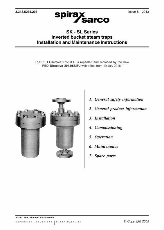
3.343.5275.203 Issue 5 - 2013
© Copyright 2005E X P E R T I S E S O L U T I O N S S U S T A I N A B I L I T Y
SK - SL SeriesInverted bucket steam traps
Installation and Maintenance Instructions
1. General safety information
2. General product information
3. Installation
4. Commissioning
5. Operation
6. Maintenance
7. Spare parts
The PED Directive 97/23/EC is repealed and replaced by the new PED Directive 2014/68/EU with effect from 19 July 2016.

ATTENZIONELavorare in sicurezza con apparecchiature
in ghisa e vaporeWorking safely with cast iron products on steamInformazioni di sicurezza supplementari - Additional Informations for safety
Lavorare in sicurezza con prodotti in ghisa per linee vaporeI prodotti di ghisa sono comunemente presenti in molti sistemi a vapore. Se installati correttamente, in accordo alle migliori pratiche ingegneristiche, sono dispositivi totalmente sicuri. Tuttavia la ghisa, a causa delle sue proprietà meccaniche, è meno malleabile di altri materiali come la ghisa sferoidale o l’acciaio al carbonio. Di seguito sono indicate le migliori pratiche ingegneristiche necessarie per evitare i colpi d'ariete e garantire condizioni di lavoro sicure sui sistemi a vapore.
Movimentazione in sicurezzaLa ghisa è un materiale fragile: in caso di caduta accidentale il prodotto in ghisa non è più utilizzabile. Per informazioni più dettagliate consultare il manuale d'istruzioni del prodotto.Rimuovere la targhetta prima di effettuare la messa in servizio.
Working safely with cast iron products on steamCast iron products are commonly found on steam and condensate systems. If installed correctly using good steam engineering practices, it is perfectly safe.
However, because of its mechanical properties, it is less forgiving compared to other materials such as SG iron or carbon steel.The following are the good engineering prac-tices required to prevent waterhammer and ensure safe working conditions on a steam system.
Safe HandlingCast Iron is a brittle material. If the product is dropped during installation and there is any risk of damage the product should not be used unless it is fully inspected and pressure tested by the manufacturer. Please remove label before commissioning

VaporeSteam
Flusso Flow
Esempi di esecuzioni corrette ( ) ed errate ( ) sulle linee vapore:Steam Mains - Do's and Dont's:
Flusso Flow
Prevenzione dai colpi d’ariete - Prevention of water hammerScarico condensa nelle linee vapore - Steam trapping on steam mains:
Intervalli di 30÷50 m. intervals
Pendenza - Gradient 1:100VaporeSteam
Gruppo di scaricoTrap set
Condensa - Condasate
Pendenza - Gradient 1:100
Gruppo di scaricoTrap set
Gruppo di scaricoTrap set
Condensa - CondasateCondensa - Condasate
VaporeSteam

Prevenzione delle sollecitazioni di trazionePrevention of tensile stressingEvitare il disallineamento delle tubazioni - Pipe misalignment:
Installazione dei prodotti o loro rimontaggio post-manutenzione:Installing products or re-assembling after maintenance:
Evitare l’eccessivo serraggio.Utilizzare le coppie di serraggio
raccomandate.Do not over tighten.
Use correct torque figures.
Per garantire l’uniformità del carico e dell'allineamento, i bulloni delle flange devono essere serrati in modo
graduale e in sequenza, come indicato in figura.Flange bolts should be gradually tightened across
diameters to ensure even load and alignment.
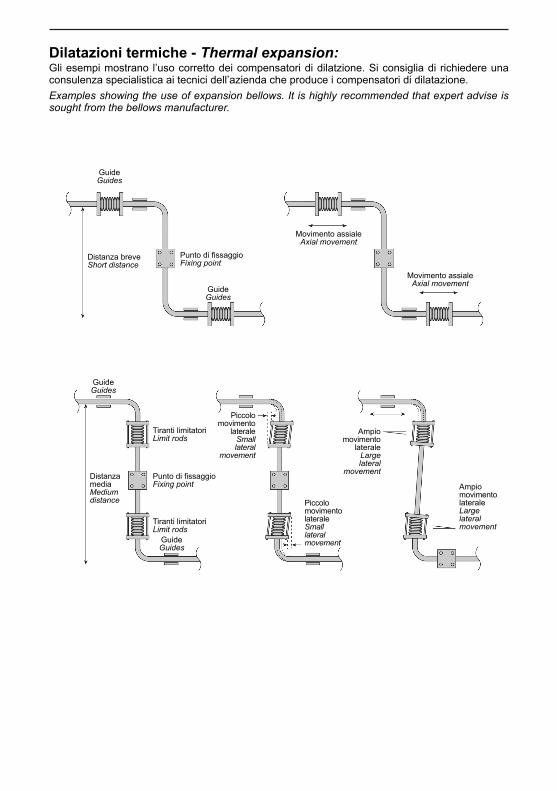
Dilatazioni termiche - Thermal expansion:Gli esempi mostrano l’uso corretto dei compensatori di dilatzione. Si consiglia di richiedere una consulenza specialistica ai tecnici dell’azienda che produce i compensatori di dilatazione.Examples showing the use of expansion bellows. It is highly recommended that expert advise is sought from the bellows manufacturer.
GuideGuides
Distanza breveShort distance
Punto di fissaggioFixing point
Movimento assialeAxial movement
Distanza media Mediumdistance
Tiranti limitatoriLimit rods
Piccolo movimento
lateraleSmall lateral
movement
Piccolo movimento lateraleSmall lateralmovement
Ampio movimento
lateraleLarge lateral
movement
Ampio movimento lateraleLarge lateralmovement
GuideGuides
GuideGuides
GuideGuides
Punto di fissaggioFixing point
Tiranti limitatoriLimit rods
Movimento assialeAxial movement

3.343.5275.2032
1. General safety informationInstallation and Maintenance InstructionsSafe operation of these products can only be guaranteedif they are properly installed, commissioned, used and maintained by qualified personnel (seeSection 1.11 on this document) in compliance with the operating instructions.General installation and safety instructions for pipeline and plant construction, as well as theproper use of tools and safety equipment must also be complied with.
1.1 Intended useReferring to the Installation and Maintenance Instructions, name-plate and Technical InformationSheet, check that the product is suitable for the intended use/application. These productscomply with the requirements of the European Pressure Equipment Directive 97/23/EC and carrythe CE mark when so required. The products fall within the following Pressure EquipmentDirective categories:
Group 1 Group 2 Group 1 Group 2Product Gases Gases Liquids LiquidsSKA, SLA DN 15 - 20 - SEP - SEPSKB, SLB DN 20 - 25 - SEP - SEPSKC, SLC DN 25 - 40 - SEP - SEPSKD, SLD DN 40 - 50 - 1 - SEP
SKF, SLF DN 80 - 1 - SEP
1.2 AccessEnsure safe access and if necessary a safe working platform (suitably guarded) before attemptingto work on the product. Arrange suitable lifting gear if required.
1.3 LightingEnsure adequate lighting, particularly where detailed or intricate work is required.
1.4 Hazardous liquids or gases in the pipelineConsider what is in the pipeline or what may have been in the pipeline at some previous time.Consider: flammable materials, substances hazardous to health, extremes of temperature.
1.5 Hazardous environment around the productConsider: explosion risk areas, lack of oxygen (e.g. tanks, pits), dangerous gases, extremes oftemperature, hot surfaces, fire hazard (e.g. during welding), excessive noise, moving machinery.
1.6 The systemConsider the effect on the complete system of the work proposed. Will any proposed action(e.g. closing isolation valves, electrical isolation) put any other part of the system or any personnelat risk? Dangers might include isolation of vents or protective devices or the rendering ineffectiveof controls or alarms. Ensure isolation valves are turned on and off in a gradual way to avoidsystem shocks.
I) These products have been specifically designed for use on steam, air or condensate /water, which is in Group 2 of the above mentioned Pressure Equipment Directive. Theproducts’ use on other fluids may be possible but, if this is contemplated, Spirax Sarcoshould be contacted to confirm the suitability of the product for the application beingconsidered.
II) Check material suitability, pressure and temperature and their maximum and minimum values.If the maximum operating limits of the product are lower than those of the system in whichit is being fitted, or if malfunction of the product could result in a dangerous overpressure orovertemperature occurrence, ensure a safety device is included in the system to preventsuch over-limit situations.
III) Determine the correct installation situation and direction of fluid flow.IV) Spirax Sarco products are not intended to withstand external stresses that may be induced
by any system to which they are fitted. It is the responsibility of the installer to considerthese stresses and take adequate precautions to minimise them.
V) Remove protection covers from all connections before installation.
3.343.5275.203 3
1.7 Pressure systemsEnsure that any pressure is isolated and safely vented to atmospheric pressure.Consider double isolation (double block and bleed) and the locking or labelling of closed valves.Do not assume that the system has depressurised even when the pressure gauge indicateszero.
1.8 TemperatureAllow time for temperature to normalise after isolation to avoid danger of burns.
1.9 Tools and consumablesBefore starting work ensure that you have suitable tools and/or consumables available. Useonly genuine Spirax Sarco replacement parts.
1.10 Protective clothingConsider whether you and/or others in the vicinity require any protective clothing to protectagainst the hazards of, for example, chemicals, high /low temperature, radiation, noise, fallingobjects, and dangers to eyes and face.
1.11 Permits to workAll work must be carried out or be supervised by a suitably competent person. Installation andoperating personnel should be trained in the correct use of the product according to the Installationand Maintenance Instructions.Where a formal ‘permit to work’ system is in force it must be complied with. Where there is nosuch system, it is recommended that a responsible person should know what work is going onand, where necessary, arrange to have an assistant whose primary responsibility is safety.Post ‘warning notices’ if necessary.
1.12 HandlingManual handling of large and/or heavy products may present a risk of injury. Lifting, pushing,pulling, carrying or supporting a load by bodily force can cause injury particularly to the back.You are advised to assess the risks taking into account the task, the individual, the load and theworking environment and use the appropriate handling method depending on the circumstancesof the work being done.
1.13 Residual hazardsIn normal use the external surface of the product may be very hot. If used at the maximumpermitted operating conditions the surface temperature of some products may reach very hightemperatures (500°C). Many products are not self-draining. Take due care when dismantling orremoving the product from an installation (refer to ‘Maintenance instructions’).
1.14 FreezingProvision must be made to protect products which are not self-draining against frost damage inenvironments where they may be exposed to temperatures below freezing point.
1.15 Safety information – Product specificSee the specific details relating to the product in the following “Maintenance” section.
1.16 DisposalUnless otherwise stated in the Installation and Maintenance Instructions, this product is recyclableand no ecological hazard is anticipated with its disposal providing due care is taken.
1.17 Returning productsCustomers and stockists are reminded that under EC Health, Safety and Environment Law,when returning products to Spirax Sarco they must provide information on any hazards and theprecautions to be taken due to contamination residues or mechanical damage which may presenta health, safety or environmental risk. This information must be provided in writing includingHealth and Safety data sheets relating to any substances identified as hazardous or potentiallyhazardous.
3.343.5275.2034
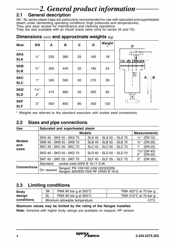
2. General product information2.1 General descriptionSK - SL series steam traps are particularly recommended for use with saturated and superheatedsteam under demanding operating conditions (high pressures and temperatures).They give easy access for maintenance and cleaning operations.They are also available with an inbuilt check valve (only for series 55 and 70).
2.2 Sizes and pipe connectionsUse Saturated and superheated steam
Models Measurements
ModelsSKA 40 - SKA 55 - SKA 70 SLA 40 - SLA 55 - SLA 70 ½" (DN 15)
andSKB 40 - SKB 55 - SKB 70 SLB 40 - SLB 55 - SLB 70 ¾" (DN 20)
sizesSKC 40 - SKC 55 - SKC 70 SLC 40 - SLC 55 - SLC 70 1" (DN 25)
SKD 40 - SKD 55 - SKD 70 SLD 40 - SLD 55 - SLD 70 1½"(DN 40)2" (DN 50)
SKF 40 - SKF 55 - SKF 70 SLF 40 - SLF 55 - SLF 70 3" (DN 80)
ConnectionsStandard: socket weld ANSI B 16.11 S.W.
On request: flanged: PN 100/160 (UNI 2223/2229)flanged: 600/900/1500 RF (ANSI B 16.5)
Dimensions (mm) and approximate weights (kg)
Mod. DN A B C D Weight*
SKA½" 235 380 25 165 18
SLA
SKB¾" 265 440 25 165 24
SLB
SKC1" 345 560 40 210 39
SLC
SKD 1½"415 680 40 265 65
SLD 2"
SKF3" 550 800 60 400 120
SLF
D
AC
B
* Weights are referred to the standard execution with socket weld connections.
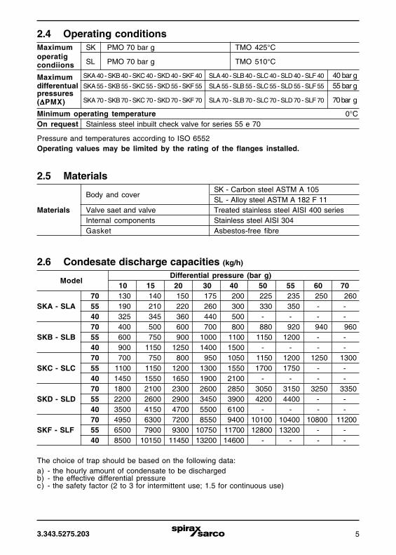
2.3 Limiting conditionsBody SK PMA 90 bar g at 350°C TMA 425°C at 70 bar gdesign SL PMA 90 bar g at 350°C TMA 510°C at 70 bar gconditions Minimum allowable temperature -12°C
Maximum values may be limited by the rating of the flanges installedNote: Versions with higher body ratings are available on request; HP version
3.343.5275.203 5
2.5 Materials
Body and coverSK - Carbon steel ASTM A 105SL - Alloy steel ASTM A 182 F 11
Materials Valve saet and valve Treated stainless steel AISI 400 seriesInternal components Stainless steel AISI 304Gasket Asbestos-free fibre
2.6 Condesate discharge capacities (kg/h)
ModelDifferential pressure (bar g)
10 15 20 30 40 50 55 60 7070 130 140 150 175 200 225 235 250 260
SKA - SLA 55 190 210 220 260 300 330 350 - -40 325 345 360 440 500 - - - -70 400 500 600 700 800 880 920 940 960
SKB - SLB 55 600 750 900 1000 1100 1150 1200 - -40 900 1150 1250 1400 1500 - - - -70 700 750 800 950 1050 1150 1200 1250 1300
SKC - SLC 55 1100 1150 1200 1300 1550 1700 1750 - -40 1450 1550 1650 1900 2100 - - - -70 1800 2100 2300 2600 2850 3050 3150 3250 3350
SKD - SLD 55 2200 2600 2900 3450 3900 4200 4400 - -40 3500 4150 4700 5500 6100 - - - -70 4950 6300 7200 8550 9400 10100 10400 10800 11200
SKF - SLF 55 6500 7900 9300 10750 11700 12800 13200 - -40 8500 10150 11450 13200 14600 - - - -
2.4 Operating conditionsMaximum SK PMO 70 bar g TMO 425°Coperatig
SL PMO 70 bar g TMO 510°CcondiionsMaximum SKA 40 - SKB 40 - SKC 40 - SKD 40 - SKF 40 SLA 40 - SLB 40 - SLC 40 - SLD 40 - SLF 40 40 bar gdifferentual SKA 55 - SKB 55 - SKC 55 - SKD 55 - SKF 55 SLA 55 - SLB 55 - SLC 55 - SLD 55 - SLF 55 55 bar gpressures
SKA 70 - SKB 70 - SKC 70 - SKD 70 - SKF 70 SLA 70 - SLB 70 - SLC 70 - SLD 70 - SLF 70 70 bar g(ΔΔΔΔΔPMX)Minimum operating temperature 0°COn request Stainless steel inbuilt check valve for series 55 e 70
Pressure and temperatures according to ISO 6552Operating values may be limited by the rating of the flanges installed.
The choice of trap should be based on the following data:a) - the hourly amount of condensate to be dischargedb) - the effective differential pressurec) - the safety factor (2 to 3 for intermittent use; 1.5 for continuous use)

3.343.5275.2036
3. InstallationIt is essential that installation is carried out correctly, observing the instructions given below.Do not let foreign bodies cause the steam trap to malfunction and put it out of service in a shorttime; flush out pipes before the start up.
3.1 Check that the trap is suitable for the effective maximum differential pressure (ΔPMX)and operating pressure (PMO) in the system.
3.2 Install the trap only vertically with the cover at the top (inlet at the bottom and exit fromthe top).
3.3 The use of an upstream protection strainer is always recommended, and it is better ifpreceded by a separation pocket with blow off valve (Fig. 1 and 2), especially in thepresence of dirty or high pressures.
3.4 If the trap is used at maximum capacity, the piping downstream of the trap needs to bethe proper size.Generally speaking, one or two DN above the trap connection is enough.
3.5 With very low steam capacities and/or superheated steam, it is advisable to install acheck valve upstream of the trap.This valve is available on request incorporated in the trap.Prime the trap by pouring a few litres of water into the body, introducing it from the topconnection, before connecting the trap to the network.
3.6 If the system is required to operate on a continuous basis, arrange for a shut-off valveto be installed upstream and a bypass; add a downstream valve in the case of pipedreturn line.
3.7 In the case of a raised condensate return system, a check valve should be fitteddownstream of the trap (unless it is already installed upstream or incorporated as atpoint 3.5).
Legend: Manual exclusion, by-pass and bleed valvesProtection filtersNote the increased discharge pipe cross-section to allow space for flashing
Fig. 1 - Line separator drainage Fig. 2 - Turbine stage drainage

3.343.5275.203 7
4. CommissioningAfter installation or maintenance, ensure that the system is fully functioning. Carry out tests onany alarms or protective devices.
Operation is completely automatic for the removal of both air and incondensable gases, which,if present in large quantities, may also require the installation of an air eliminator in parallel.The special valve lever-bucket connection eliminates all friction with the side wall: closure isinstantaneous, without steam leaks and operation is with blast type discharges, easily measurablein order to check trap operation.
5. Operation
Before undertaking any maintenance on the trap, it must be isolated from both the supply line andreturn line and any pressure allowed to safely normalise to atmosphere.The trap should then be allowed to cool. When reassembling, ensure that all joint faces areclean.
6.1 For a complete inspection of the trap, remove the cover by unscrewing the bolts. Cleanthe valve mechanism of any deposits and fouling, and ensure that the air vent hole (H)in the bucket is completely free of obstructions.
6.2 To replace the valve seat, remove the valve mechanism by unscrewing the twoscrews (C).When replacing the valve seat, it is also advisable to replace the valve plug/leverassembly (G) (E), which is removed by undoing the split-pin (D).It is also advisable to replace the cover gasket (I).
6.3 To replace the bucket (L) slip off the top pin fixing it to the lever.
6. Maintenance

REPAIRSPlease contact our nearest Branch Office or Agent, or directly Spirax-Sarco S.r.l.Via per Cinisello, 18 - 20834 Nova Milanese (MB) - Tel.: 0362 49 17.1 - Fax: 0362 49 17 307
LOSS OF GUARANTEETotal or partial disregard of above instructions involves loss of any rights to guarantee.
3.343.5275.203 Issue 5 - 2013.09
Spirax-Sarco S.r.l. - Via per Cinisello, 18 - 20834 Nova Milanese (MB) - Tel.: 0362 49 17.1 - Fax: 0362 49 17 307
7. Spare parts
How to order sparesAlways order spare parts by using the description given in the table and state the type of trap,pressure rating and diameter of the connections.Example: 1 - Valve assembly for an SLB 55 trap, DN ¾”.
Fig. 3
E
F
G
(H)
I
L
A
B
C
D
A = Valve seatB = BracketC = Bracket screwsD = Split pinE = Valve headF = Lever PinG = LeverH = HoleI = Cover gasketL = Bucket
The available parts are indicated in the tableand can be seen in the drawing. They areavailable according to the grouping given inthe table. No other parts can be supplied asa spare part.
Available sparesValve assembly A, B, C, D, E, F, G, IBucket assembly D, F, I, LGasket set (3 pieces) I