SJI - DTIC
169
AD/A-005 620 EMP ISOLATION PROVIDED BY LARGE FARADAY-SHIELDED TRANSFORMERS Boeing Aerospace Company Prepared for: Army Engineer Division December 1974 DISTRIBUTED BY: National Technical Information Service U. S. DEPARTMENT OF COMMERCE SJI
Transcript of SJI - DTIC

AD/A-005 620
EMP ISOLATION PROVIDED BY LARGEFARADAY-SHIELDED TRANSFORMERS
Boeing Aerospace Company
Prepared for:
Army Engineer Division
December 1974
DISTRIBUTED BY:
National Technical Information ServiceU. S. DEPARTMENT OF COMMERCE
SJI

Uncl assifiedSECURITY CLASSIFICATION OF THIS PAGE (When k)ete intered)
REPORT DOCUMENTATION PAGE RBE ,RD INSTRUCTIONS__________________________________________ BLOR1• COMA rLETING FORMSREPORT NUMBER 2. GOVT ACCESSION NO. 3. •E CIPIENT'S CATALOG NUMBER
"" Tlechnical Memorandum 82 0a. /0 A0•"•
4. TITLE fand S~ibltl e) S. TYPE OF REPORT & PERIOCO COVERED
EMP Isolation Provided by Large Faraday-Shielded Final ReportTransformers
6. PERFORMING ORG. REPORT NUMBER
I". AUTHOR(s) 8. CONTRACT OR GRANT NUMBER(O)
Boeing Aerospace Company DACA87-72-C-0002 MOD T
9 PERFORMING ORGANIZATION NAME AND ADDRESS 10. PROGRAM ELEMENT. PROJECT, TASK
AREA & WORK UNIT NUMBERS
Boeing Aerospace Company Appendix A, Annex BP.O. Box 3999 Para. 2.h.(d)(d)Seattle, Washinqton 98124 Para. 2.h.(4)(d)
I1. CONTROLLING OFFICE NAME AND ADDRESS 12. REPORT DATE
U.S. Army Engineering Division December 1974106 Wynn Drive, NW, Huntsville, Alabama 13. NUMP M9 CAGES
"14 M:;iITORING AGENCY NAME & ADDRESS(if different from Controlling Office) IS. SECURITY CLASS. (of this rsportý
UnclassifiedSame as 11
15e, DECLASSIFICATION, DOWNGRADING
SCHEDULE
16. OISTRIBUTION STATEMENT (of thi Report) I ST W,. ,.. ,iW ,J
"Approved for pubia mleuMDstributon Ur~lIzid
7•. DISTRIBUTION STATEMENT (of the abstract entered in Block 20, it different from Report)
Same as 16
IS. SUPPLEMENTARY NOTES R.y-o-d by
NATIONAL TECHNICALINFORMATION SERVICE
I .i S U , : . , t A 22o 151r Ce
19. KEY WOFDS (Continue an reverse aide It necoeeary and identify by block numher)
EMP RegulatorFaraday Shield TransformerIsolation
20 ABSTRACT (Continue on reverie side If neceeesry and identify hi blocK number)
The pulse response .of a variety of power transformers was determined, withemphasis on Faraday-shielded transformers. Tests were conducted nn seventransformers and an Inductrol regulator at the SAFEGUARD North Dakota site.The transformers range in size from 10 MVA to 250 VA. The analysis prngramused the test results to the transformer characteristics, and to calculatethe shielding effectiveness of the transformers for a variety of 'Inputconditions, loads, and wiring configurations.
.. FOR 1 47 u'DD U JAN 73 1473 EDITION OF I NOV 65 IS OBSOLETE I _0 M e!
SECURITY CLASSIFICATION Or, THIS PAGE (When eata E'ntered)

TECHNICAL MEMORANDUM
TM-82
EMP ISOLATION PROVIDED BY LARGE FARADAY-SHIELDED TRANSFORMERS
SUBMITTED BY
BOEING AEROSPACL COMPANY
SEATTLE, WASHINGTON
PREPARED FOR
U.S. ARMY ENGINEERING DIVISION, HUNTSVILLE
CORPS OF ENGINEERS
CONTRACT DACA87-72-C-0002
DDC
•, 27 1975
DECEMBER 1974
D
DUISTSA1hf!
Approvt'd for pubic€ rele.lcD1imhUl n UnlmahW

TM-82
ABSTRACT
The pulse response of a variety of power transformers was determined,
with emphasis on Faraday-shielded transformers. Tests were conducted
on seven transformers and an Inductrol regulator aý the SAFEGUARD NQrth
Dakota site. The transformers range in size from 10 MVA to 250 'V.
The analysis program used the test results to the transformer character-
istics, and to calculate the shielding effectiveness of the transformer's
!or a variety of input conditions, loads, and wiring configurations.
KEY WORDS
EMP Regulator
Faraday-Shield TransformerIsolation
i
i

TM-82
TABLE OF CONTENTS
PAGE
1.0 TRANSFORMER ANALYSIS SUMMARY 11.1 Objective 11.2 Scope I1.3 Approach 11.4 Assumptions 41.5 Suminary of Results 5
2.0 TEST AND ANALYSIS PROGRAM 122.1 Measurement Technique 1.22.2 Calculation Technique i82.3 Capacitive Pi Network 31
3.0 DETAILED RESULTS 33
4.0 POWER SUBSYSTEM ANALYSIS 122
5.0 DATA FLOW EXAMPLE 134
IU,

TM-82
S- LIST OF FIGURES
NUMBER PAGE
1 Example Power System 13
2 Two-Port Parameters 14
3 Mode l 15
4 Mode 2 16
5 Mode 3 17
6 Mode 5 19
7 Mode 1A & 2A 20
8 Mode 3A 21
9 Mode 4A, Inductrol Regulator 22
10 General Spectrum of Double Exponential Pulse 24
11 Pulse Frequency Ranges 26
12 Data Flow Summary 27
13 Data Flow Diagram - Part I 28
14 Data Flow Diagram - Part II 29
15 Data Flow Diagram -. Part Ill 30
16 PI 1004 32
17 Mode 1 37
18 Mode 1 37
19 Mode 1 38
20 Mode 1 38
21 Mode 1 39
22 Mode l 39
23 Mode 1 42
24 Mode 1 42
25 Mode I 43
26 Mode 1 4?
27 Mode 1 #4
28 Mode l 44
29 Mode 1 47
30 Mode 1 44
iiii

TM-82
LIST OF FIGURES (CONT.)
31 Mode 1 4832 Mode 1 4833 Mode 1 4934 Mode 1 4935 Mode 1 52
36 Mode 137 Mode 1 5338 Mode 1 5439 Mode 1 5440 Mode 2 5741 Mode 2 5742 Mode 2 5843 Mode 2 5844 Mode 2 6145 Mode 2 61"46 Mode 2 6247 ;\'iode 2 6348 Mc.de 2 6349 Mode 3 6650 Mode 3 6651 Mode 3 6752 Mode 3 C7
53 Mode 3 6854 Mode 3 6855 Mode 1 7156 Mode 1 7157 Mode 1 7258 Mode 1 7259 Mode 1 7360 Mode 1 73
iii

•-WIW7 -7-.
-TM-82
LIST OF FIGURES (CONT.)
61 Mode 2 76
62 Mode 2 76"63 Mode 2 7764 Mode 2 77
65 Mode 2 7866 Mode 2 78
67 Mode 2 80
68 Mode 2 8169 Mode 2 82
70 Mode 1 85
7L Mode 1 8572 Mode 1 86
73 Mode 1 8674 Mode 1 87
75 Mode 1 8776 Miode 2 90
77 Mode 2 9078 Mode 2 91
79 Mode 2 9180 Mode 5 9481 Mode 5 9482 Mode 5 9583 Mode 5 95
84 Mode 1A 9885 Mode 2A 9886 Mode 1A 99
87 Mode 2A 99I 88 Mode 3A 102
89 Mode 3A 102
90 Mode 3A 103
iv

TM-82
LIST OF FIGURES (CONT.)
91 Mode 3A 103
92 Mode 3A 104
93 Mode 3A 104
94 Mode 3A 105
95 Mode 3A 10596 Mode 4A Boost 11097 Mode 4A Boost 110
98 Mode 4A Boost 11199 Mode 4A Boost 111
100 Mode 4A Boost 112101 Mode 4A Boost 112102 Mode 4A Boost 113103 Mode 4A Boost 113104 Mode 4A Buck 118105 Mode 4A Buck 118106 Mode 4A Buck 119107 Mode 4A Buck 119
108 Mode 4A Buck 120
109 Mode 4A Buck 120110 Mode 4A Buck 121
il1 Mode 4A Buck 121
112 Assumed Termination Impedance Attached to Outer 123End of Buried Cable
113 Assumed Load Impedance Attached to Outer End of 12350 Foot Load Cable
114 Transient Voltage Waveform at Transformer Input 126
115 Transient Current Waveform at Transformer Input 127116 Transient Voltage Waveform at Transformer Output Terminals 128117 Transient Current Waveform at Transformer Output Terminals 129
118 Transient Voltage Waveform at Load Terminals 130119 Transient Current Waveform at Load Terminals 131
V

TM-82
LIST OF FIGURES (CONT.)
120 Magnitude of Voltage Spectrum at T-1004 Input Terminals 132from i ZAPTST Case Using P-5 Pulse
121 Magnitude of Voltage Spectrum at T-1004 Input Terminals 133from the ZAPTRN Case Reported in Table 1
122 TF12 Y11 Amplitur' Data 135
123 TF12 Y11 Phase Dana 136
"124 TF12 Y12 Amplitude Data 137125 TF12 Y12 Phase Data 138
126 TF12 Y22 Amplitude Data 139127 TF12 Y22 Phase Data 140
128 TF12 A Parameter Magnitude 141
129 TF12 A Parameter Phase 142130 TF12 B Parameter Magnitude 143
131 TF12 B Parameter Phase 144
132 TF12 C Parameter Magnitude 145133 TF12 C Parameter Phase 146
134 TF12 D Parameter Magnitude 147
135 TF12 D Parameter Phase 148136 TF12 ABCD Determinant Magnitude 149
137 TF12 ABCD Determinant Phise 150
138 TF12 Open Circuit Voltage Transfer RationMagnitude 151139 TF12 Open Circuit Voltage Transfer Ratio Phase 152
140 TF12 Loaded Voltage Transfer Ratio 153141 TF12 Imput (Y) Pulse Spectrum (P5) 154
142 TFi? Input (Y) Pulse Amplitude 155
143 TF12 Output (A) Pulse Spectrum 156
144 TF12 Output (L) Pulse Amplitude 157
vi

TM-82
LIST OF TABLESNUMBER PAGE
1 Transformers Tested 62 Definitions of Modes 83 Data Summary 94 Inductrol Regulator Data Summary 115 Pulse Parameters 255a Calculations Summary 346 Transformer TF12 357 Transformer TF12 368 Transformer TF12 409 T-ansformer TF12 41
10 Transformer TFAA/FA 4511 Transformer TFAA/FA 4612 Transformer TFAA/FA 5013 Transformer TFAA/FA 5114 Transformer TFAA/FA 5515 Transformer TFAA/FA 56lb Transformer TFAA/FA 5917 Transformer TFAA/FA 6018 Transformer TFAA/FA 6419 Transformer TFAA/FA 6520 Transformer TF1004 6921 Transformer TF1004 7022 Transformer TF1004 7423 Transformer TF1004 7524 Transformer TF1004 7925 Transforiner TF110 8326 Transformer 1010 8427 Transformer 1010 8828 Transformer 1010 8929 Transformer 1010 92
vii

TM-82
LIST OF TABLES (CONT.)
30 Transformer TF1010 93
31 Transformer Control 9632 Transformer Control 97
33 Transformer T17363 100
34 Transformer T17363 10i
35 Regulator 106
36 Regulator 108
37 Regulator 11438 Regulator 116
39 Summary of Computer Results 125
viii

TM-82
1.0 TRANSFORMER ANALYSIS SUMMARY
1,1 OBJECTIVE
In tha analysis of EMP propagation in power systems, evaluation of the isola-
tion provided by the power transformers is required. Some major sources of
EMP coupling into a power system are overhead lines, buried cables, unshield-
ed equipment, etc. Critical areas are isolated by shields, filters, transform-
ers, switchgear, etc. The numerical values for the EMP isolation provided by
these isolation devices are needed for the calculation of EMP levels at vari-
ous locations throughout the power system. The objective of this study was
to determine the EMP shielding effectiveness of the types of transformers
used in the SAFEGUARD System.
1.2 SCOPE
A test and analysis program was developed and completed to characterize
the pulse response of a variety of power transformers, with emphasis on
Faraday-shielded transformers. Tests were conducted on seven transformers
and an Inductrol regulator at the SAFEGUARD North Dakota site. The trans-
formers range in size from 10 MVA to 250 VA. Five are three-phase shielded,
two are single-phase unshielded. The analysis program used the test results
to determine the transformer characteristics, and to calculate the shielding
effectiveness of the transformers for a variety of input conditions, loads,
and wiring configurations.
1.3 APPROACH
To establish the basic approach to the determination of EMP isolation pro-
vided by large Faraday-shielded transformers, a definition of what is meant
by "transformer isolation" is required, suitable test data is needed, and
both input-output circuitry and disturbing pulse shapes must be specified.

TM-82
1.3 (Continued)
For purposes of this study, "transformer isolation" is defined as1) the ratio of peak-output to peak-input pulse currents under selectedconditions, and 2) the ratio of peak-output to peak-input pilse voltagesunder selected conditions. The selected conditions involve tht specifi-cation of appropriate disturbing pulse shapes, input circuits, and load
2
md

TM-82
1.3 (Continued)
circuits, for a particular transformer type. It is necessary to note the
possibility of obtaining widely different numerical values of 'isolation for
different transformers for various selected conditions. Thus,one of the
important aspects of this study has been the choice of the selected
conditions to represent the particular applications of each transforier
to yield a response matrix for those particular applications, and to
establish the variability ur the isolation for various parameters to
permit the estimation of isolation for cases which have not been specific-
ally evaluated.
To obtain test data, the transformers were connected in various "modes"
or circuit configurations to establish two-port (black box) representations
of the propagation of EMP through the transformers. Then in general, y-parameter data for these conficurations were taken in the frequency
domain. The frequency range used for most of the swept-cw data was
30 kHz to 32 MH . Spot-cw data was obtained at 1 kHz and 50 kH . Data
up to 100 MHz was obtained for one transformer.
The input and output circuits external to the transformer are represented
by a resistive source impedance and a resistive load in most cases.
Also the response of a system, consisting cof a direct buried cable,
a transformer, another cable, and a complex load, was calculated. The
values of the resistive sources and loads for a particular transformer arebased on calculations of the equivalent transmission-line impedance of the
associated conduit, or the equivalent resistance of the associated
loads. The disturbing pulses are represented as double-exponential
pulses having suitable frequency content. The pulse response for each
transformer and each of its selected conditions was computed using Fourier
transform methods.
3

TM-82
"1.3 (Continued)
Several data processing programs were developed for reducing the
transformer data. The original frequency domain-data is in terms of
the magnitude of the y parameters and the associated phase. This data is
digitized, then converted to ABCD parameters by the ABCDOF program. The
ABCD parameters are the most useful for system calculations, since theABCD parameters for system elements can be chained together to represent
larger portions of a system. Such a calculation is shown in Appendix A.The data was originally taken in terms of y parameters because a single-
point ground can be readily established for thi associated measurement
circuitry. The ABCDOF program produces 1024 complex numbers per parameter,to represent a particular transformer. These parameters can be stored
on tape and used by the ZAPTST program to compute pulse response for the
selected conditions. As an alternative, the ABCDOF output can be input
to the SHAKER routine, which selects the 98 most significant complexnumbers per parameter for output on cards. The accuracy of SHAKER is
readily checked by comparing plots uf the ABCD parameters from SHAKER
with the ABCDOF output plots. The current technique for use of SHAKER
(input of inverse ABCD parameters) has been found to provide excellent
accuracy in most cases. The availability of the transformer ABCD
parameters on cards from SHAKER has been very convenient for some
applications. The SHAKER output in addition to the direct ABCDOF output,is used by the ZAPTST program to compute pulse response for the selected
conditions.
1.4 ASSUMPTIONS
The approach for the determination of transformer isolation for this
study rests on several assumptions which are implicit in the above
discussion, The basic assumptions are:
4

TM-82
1.4 (Continued)
1) That transformer isolation can be defined as:a) The ratio of peak-output to peak-input pulse currents under selected
load conditions, and
b) The ratio of peak-output to peak-input pulse voltages under selectedload conditions.
2) That the double-exponential pulse, with the particular set of time con-stants used for this study, is a suitable representation of the threat-induced pulses.
3) That the source and load impedances can be adequately represented byselected values of resistance.
4) That the two-port configurations, or modes, properly represent thepropagation of EMP through the transformers.
5) That the test-instrumentation configuration accurately measured thetwo-pcrt parameters.
6) That the data-processing procedure resulted in meaningful calculationsof the pulse amplitudes.
These assumptions are reasonable, and are in agreement with test resultsobtained at the North Dakota SAFEGUARD. Site tests were directed primarilyat overall verification and were not planned to verify each assumptionseparately.
1.5 SUMMARY OF RESULTS
The transformers listed in table I were measured. The type of measurementstaken and -che data used for the isolation calculations also are given i-this table.
The TFCP-l, 10 MVA, ll5KV-4160V, 30 transformer was tested with theprimary (A) terminals shorted and driven against ground with a pulsegenerator. The secondary (y) wires were individually leaded with 17-ohmresistors to ground. The neutral (y) was grounded,
5

I--S
La.J LLJ LAJ A
6-.4 I- (.) Laiuij C3 zA a LO
V) ac LLJ W W < AA
m- WcI-L
C-1 C3C.--
ca C3
_k LiJ
.I wo -7 W
0) a 04n CA w0
u.. V) C3 D C
0-
V)j. 0i V)J LLI.LI V) L
u S Au L L AJ Li.I
B- B -i qw LA I- aL
qx 00 X: 0: C)swi , so j gL~ g-
.LJ L.J Z: C)aJ 4 ~g~~ 4 ~ 4 >(4 WLA- >-LJ .. > ULAJ - cn >-i ~~LAJ W >-r4 > W C L
CL LA 0l C- lCr AOl u V
SC"J fn B---Liw .i- <
CO r-. ýM .
-V m a 1- L" 6

TM-82
1.5 (Continued)
For the drive pulse, the observed t was 60 nsec, consistent with
values of f = 8 x 10⁵ Hz, f = 6 x 10⁶ Hz from the calculated Fourier
transform (see Chapter 2). The peak pulse current transfer ratio wasmeasured to be -27 dB with shield connected, and -24 dB with shielddisconnected. The cw transfer function showed a pronounced resonance
(minimum attenuation) at 106 Hz, where the attenuation was -22 dB.These values seen approximately consistent with the more detailed
analysis of the other transformers. The definitions of the differentconfigurations, or modes, are given in table 2. A total of 381 diff-erent combinations of pulse shape, input resistance, and output resistancewere used in transformer calculations. Table 2 shows the values of
source and load resistance which correspond to the data summary intable 3. The pulse-time constants (P5) were 4 x 10⁶ and 5 x 10⁸ sec"1
for this table.
From table 3, it can be seen that for shielded transformers, with the
shield connected, and for Mode 1, which is the most pertinent mode, forthe worst-case loading, the transformers provide at least 6-dB isolationfor pulse propagation from Y to L, and at least 10-dB isolation forpropagation from A to Y. For the nominal source and load resistances,
at least 12-dB isolation for Y to A and at least 16-dB isolation A to Yis shown. For the low-impedance secondary (Y) load, at least 10-dBisolation from Y to 6 and at least 30-dB isolation from L to Y is found.The differential modes show significantly more isolation.
Source-impedance variations have small effect on isolation. In mostcases a low-impedance source (20) shows slightly less isolation (0-6 dB)than high values.
7

TM-82
TABLE 2 DEFINITIONS OF MODES
MODE 1: COMMON MODE .6 %`COMMON M 'D Y,* NEUTRAL GROUNDED
MODE 2: COMMON MODE A, CONVION MODE Y, NEUTRAL UNC-ROUNDEfl
MODE 3: DIFFERENTIAL MODE A , COMMON MODE Y , NEUTRAL GROUNDED
MODE 5: DIFFERENTIAL MODE A ,DIFFERENTIAL MODE Y, NEUTRAL GROUNDED
MODE IA COMMON MODE PRIMARY, DIFFERENTIAL MODE SECONDARY SINGLEPHASE TRANSFORMER
MODE 2A: DIFFERENTIAL MODE PRIMARY, DIFFERENTIAL MODE SECONDARY.SINGLE PHASE TRANSFORMER
MODE 3A: COMMON MODE PRIMARY, COMMON MODE SECONDARY 'INGLE PHAVETRANSFORMER
CONDITIONS FOR DATA SUMMARY
INPUT OUTPUT ZL
WORST CASE Y aI
LO% IMPEDANCE Y 1& 2n 30n""mONDAR y 02f
NOMINAL a30jQ 30f
8

TM-82
TABLE 3 DATA SUMMARY
TN R MODE, PULSE DIRECTION VOLTAGE ISOLATIONdB,(P5)
SHIELD INPUT OUTPUT WORST CASE SECONDARY IMP NM
TF12 1 ON Y A -7 -12 -18A Y -15 -31 -19
1 OFF Y A -6 -11 -15
A Y -15 -26 -17"TFAA/FA I ON Y & -6 -12 -12
A Y -10 -33* 16
1 OFF Y a -2 -6 -9A Y .3 -25* -8
2 0N Y A .5 -12 -14a Y -9 -30* -15
2 OFF Y A 2 -8 -6A Y -4 -30" *9
3 ON Y 6 .24 -34 -28
A Y -29 -48* -30
TF1004 1 ON Y A -17 -21 -22
16 Y -16 -36* -22
2 ON Y A -17 -20 -24
A Y -17 -37* .24
W 1004 2 ON A Y --20 ý36* -24
TFl0i0 1 ON Y A -6 -10 -16
A Y -12 -30* -16
2 ON Y a -6 - -15
A Y -11 - -15
5 ON Y A "14 - -32
A Y -.1 5 -56 -32CONTROL ]A HV LV -5 -20
2A HV LV -3 - -16*T17363 3A LV HV +2 -6 -7
HV LV -3 -30* -10
*EXTRAPOLATI ON
9

TM-82
1.5 (Continued)
To disconnect the shield shows some reduction in isolation. The possibilitythat the disconnected shield still provides some isolation is indicated bythe low values of isolation provided by T17363 which is an unshielded trans-former.
The 50 kVA, 480/277-volt Inductrol regulator was tested in a single-phaseline-to-ground configuration (Mode 4A, see Chapter 2). The results aresummarized in table 4. Terminals 1 and 2 are the normal ac input and out-put terminals, respectively. The designation imput to terminal 1, outputto terminal 2 indicates pulse propagation from the normal regulator imputto its output, etc. A comparison of table 3 and table 4 indicates thatthe regulator provides less isolation than the shielded transfocrmers forworst-case and nominal loads.
Sufficiently detailed data in graphic form is provided below to permit theselection of appropriate values of isolation for many specific applications.Also, values of isolation were identified which dre generally applicablefor a power system analysis when specific values for each special case arenot desired.
For the d160V to 480V shielded transformers, values of 10-dB isolation from480V (y) to 4160V (A) and 20-dB isolation from 4160V (A) to 480V (y) wereselected for general application. For the Inductrol regulator, a value cf20-dB isolation for both pulse propagation directions was selected for gen-eral application, since the appropriate load impedances are low.
10

TM-82
TABLE 4 INDUCTROL REGULATOR DATA SUMMARY
INPUT OUTPUT ZL ZS VOLTAGE ISOLATION, dB, P5TO TERM. FROM TERM. R BOOST BUCK
1 2 1 G -2 -42 1 1 o -5 -4
1 2 1 1 -41 -44LOW IMPEDANCE2 1 1 1 -41 -44
1 2 50 50 -10 -12NOMINAL 2 1 50 50 -12 -14
11

TM-82
2.0 TEST AND ANALYSIS PROURAM
2.1 MEASUREMENT TECHNIQUE
An example power system is shown in figure 1 to illustrate how the
transformers are in the EMP flowpath from sources of pickup (enclosures,
direct buried cable, etc. to sensitive components (comrputers, cryptoequipment, etc.). Thus, the transformer isolation for the appropriateconditions is needed to properly calculate the pulse transfer to thecritical components. The transformer is considered as a four-terminal(two-port) black box (figure 2). The short-circuit admittance parameters(y parameters) were measured in the frequency domain. Figure 2 illustrates
the y parameters for a two-port network, as well as the ABCD parametersand the formulations for the worst-case voltage and current-transfer
ratios.
A three-phase shielded transformer provides so many terminals that to
characterize such a transformer completely as an n-port netwcrk isunnecessarily complex. Consequently, certain circuit configurations
(modes) have been chosen to represent the propagation of EMP through atransformer. Figure 3 shows the configuration which has been labeled"mode I", with the corresponding measurement technique. Mode Irepresents the propagation of EMP where all three-phase lines areraised to the same voltage above ground (common-mode) at both the
input and output of the transformer. For mode 1,the secondary (y)
neutral has been grounded. This configuration represents the t'ost pert-inent EMP propagation mode. Figure 4 shws mode 2, where the onlydifference from mode 1 is that the neutral has been connected to the
output terminal instead of ground. Mode 2 parameters are capacitivein the low-freauency region, simplifyinq the investigation of eQuivalent
circuits for a transformer. Figure 5 shows mode 3, where the transformer
12

S.. . . ,•t........... .. .. ...... . TM8
I-
T1--
2 >
0 *0 cc,,'A --- --- ---
: t :0
LU
& I
i _
ui a
UJJ0
- ----- --------
LL ,A I 0
- - --- - z- :
CCJ
ili
8 II
173
U. :- --. !
ci 3 3

TM-82
acru.Z
ID.-
NwZF- C
N > > cU
o 0LL. LL x -
w•
N•->+ -N ---
C1 C w- 0-
>I II II
14c
LLUC4 Z crZ
cc~2'-0
1 0
>C' ><0
NC-4 - 0:> U- cc:
++ + a w
> > > N 0 a.
U-N z < -
:3
14

TM-82
H2 I 2
H,H •H3
SHIELD
j 2
/~31* '-CASE
MEASUREMENT TECHNIQUE:
(1) SET V2 = O(SHORT)
DRIVE V
M E A SU RE Y I _! y--11
(2) SET V1 0
DRIVE "'2 122
MEASURE Y
(3) REPEAT ITH SHIELD DISC2NNEC7E0
FI',UR[ 3 MrI)L I
15

---------
Trl-82
H2
H I1n ,3
SHIELD
/Xlx1
CASE
MEASUREMENT TECHNIQUE:
(1) SET V2 = O(SHORT)
DRIVE V I 12
MEASURE Y =-'Y2 V
(2) SET V1- 0
DRIVE V2 12
MEASURE Y2 2 =--V-2
(3) REPEAT WITH SHIELD DISCONNECTED
1
3 FIGURE 4 MODE 2
16

TH-82
SHIELD
HH,11
43
"-___q Iii
CASE
,EASUREM2NT T[CHNIOUE:
(1) SET ~2' 13 = 0 (SHORT)
DRIVE V 1 I 12 13
MEASURE YV11 Y ?1 31-
"i1'' 31
(2) SET V 0 (SHORT)
DRIVE VC2
MEASURE YEA U M N 2 T 32VO2
(3) SET V1 9 V2 =O(SHORT)
DRIVE VI3 1
MEASIRIE V3 )
(4) REPEAT V ITH SHIELD DISCONNECTED
DIrVURE 5 MODE 3
17

TM-82
2.1 (Continued)
has been configured to determine the conversion of a common-mode signalon the secondary (y) tc a Jifferential-mode signal on the primary (A).or vice-versa. Mode 4 was a configuration developed to determine theconversion of a common-mode signal on the primary (A) to a differential-mode signal on the secondary (y). The dnalysis of the mode 4 data wasconsidered of low priority and was not completed. Figure 6 shows themode 5 configuiation. Mode 5 represents the propagation of a differential-mode (between wires) input signal to a differential-mode output signal.Figure 7 shows the configurations used to test the unshielded, single-phase control transformer. Mode 1A is a common-mode primary, differential-
mode secondary configuration. Mode 2A is a differential-mode primary,differential mode secondary configuration. Mode 1A and 2A were used to testthe control transformer.
Figure 8 shows the configuration used to test the unshielded, single-phase 50-kVA power transformer T17363. Mode 3A is a common-mode primary,
common-mode secondary configuration.
Figure 9 shows the configuration used to test the three-phase, 50-kVA,
480/277-volt inductrol regulator. Mode 4A is essentially a differential-mode in, differential-mode out configuration for one phase of the regulator.This configuration was chosen as most reasonable to determine theregulator line-to-ground EMP-output level from a common-mode regulatorinput pulse propagated through a common-mode transformer configiration.
2.2 CALCULATION TECHNIQUE
The majority of the measurements are made in the frequency domain.The transformer-pulse responses are calculated using Fourier-transform
techniques. The use of the combination of y-parameter measurements
18

TM -82
x H2 12
SHIELD 2
V/r Xql X.
-CASE
MEASUREMENT TECHNIQUE:
(1) SET V2 = 0 (SHORT)
DRIVE V1
EiEASURE Y - ' = - "21
(SELECT A WINDING FJR MAX 12)
(2) SET V1 = 0 (SHORT)
DRIVE V2 12
MEASURE Y2 2
(3) REPEAT WITH SHIELD DISCONNECTED
FIGURE 6 MODE 5
19

TM-82
MODE 1A 12
480V
PRIMARY 120V SECONDARY
V 3
MEASUREMENT TECHNIQUE:
(1) SET V2 , V3 : 0 (SHORT)
DRIVE V1
(2) SET V1 = 0 (SHORT)
DRIVE V2
V MODE 1B
V,,I
MEASUREMENT TECHNIQUE:
(1) SET V2 0 (SHORT)
DRIVE V1 I
MEASURE Y I1 2
(2) SET V1 =0 (SHORT)
DRIVE V2 12MEASURE Y2 2 -V
2FIGURE 7 MODE 1A & 2A
20

.' ,
120/240 V
14,760 V HlV tni 'li M-8
TRANSFORMER T 17363
MEASUREMENT TECHNIQUE:
(1) SET V 2 =0(SHORT)
DRIVE V1 I
!1014 V 2
MEASURE YI M R T N
(2) SET V2 = 0 (SHORT)
DRIVE V2 1
MEASURE Y11 - 2MEASRE 22 2
FIGURE 8 MODE 3A
21

TM-82i.'-
TERM 1 1 1 TERM 2
DISCONNECT THE DISCONNECT THENORMAL 480/277V V1 V2 NORMAL OUTPUTINPUT LINES 2 LINES
SINGLE PHASE REGULATOR
MEASUREMENT TECHNIQUE
1) Set for maximum boost
a) Set V2 =O (short)
Drive V1 12Measure Y " 21 V
b) Set V 1=O (short)
Drive V2
Measure Y22 =2• 2DriveV2
2) Repeat for maximum buck
Figure 9 Mode 4A, Inductrol Requlator
22

TM-82
2.2 (Continued)
in the frequency domain with calculation of the time-domain pulse
responses allows excellent flexibility in the choice of pulse shape,load impedance, and source impedance. The pulse-time constants arechosen to obtain the desired frequency content. Figure 10 shows the
spectrum of a double-exponential pulse. The bulk of the energy in the
pulse is between the low-frequency break point f and the high-
frequency break point f,, consequently matching of f and f, to thedesired frequency range has been the key to selection of appropriate
pulse shapes. Table 5 shows the pulse parameters which have been usedin the transformer calculations. P represents the approximate
frequency content of pulses resulting from EMI fields coupling intoinductances. The data supported the use of P1 only for T17363. 12
represents typical pulsers coupled to a transformer, P3 is ar.
approximation to a step function and did not compute properly. F4was chosen to fit the majority of the swept-cw data. P5 is typical offree-field environments, cable pickup, etc. P4 and P5 were used for
the majority of the calculations. The tp column of table 5 gives the time
to the peak for the corresponding pulse, where tp = 1 np W
Figure 11 shows the pulse-frequency ranges for PI. P4, and P5 compared
with the frequency ranges for the data. Most of the networK-analyzer
data was taken from 30 kHz to 32 MHz, except for T17363, for which the
upper frequency limit was 100 MHZ
To summarize the overall calculational approach, the data consists of yparameters which are digitized and converted to ABCD parameters, then
the pulse response is calculated using input information on either cardor tape. This summary is shown in figure 12. A more detailed dataflow is shown in figures 13, 14, and 15,which are self explanatory.
23

TM-82~
AI
C~C,
ca3
04'
Nj
+ Im V(nP
4J
-LJ
CCL
LUJ
C)
-AJ
0 W
At
cn >~
244

TM-82
TABLE 5 PULSE PARAMETERS
a(Sec- 1 ) s(Sec- 1 ) fo (Hertz) fa (Hertz) Tp (Sec)
PI 6 x 10⁷ 5 x 10⁸ 107 8 x 10⁷ 4.8 x 10⁻⁹
P2 2 x 10⁶ 3 x 10⁷ 3 x 10⁵ 5 x 10⁶ 9.8 x 10" 8
P3 0.1 1010 1.6 x 10⁻² 1.6 x 10⁹ 2.5 x 10⁻⁹
P4 4 x 10⁵ 108 6.4 x 10⁴ 1.6 x 10⁷ 5.5 x 10- 8
P5 4 x 10⁶ 5 x 10⁸ 6.4 x 10⁵ 8 x 10⁷ 9.8 x 10⁻⁹
25

F;
TM-82
a-
U) I-
a-L 14.1
c~)c0
- a-
JJ 0in
26-
•mC
n •C26
nii -
• 0

k *~ TM- 82
Vj) OýLi- CýULj
L/) *-LA LAJ1
,,-) < CLcct LLJ~ 1/)
><LU Cl-Ji CL LiiLA
0- Ud) V)
Ln L) co Cifz:0
() Lj, C>
w cl:
UI-
=) 00 X
C\.J
C) I-CD~ CL LLiL.
F- LU
C~jCD ri-
m'
V)LLMi 0. L
LAJ .--.<
L0 rL
<( m____

uj
TM -82
cr. w -
X F- zi (
cc LL cO
WJ 0 L L C C~ -jE<
ý - <C
z 0. :)~ w (n .
< aW z cc-J c
LiZ cQ ca cc LLQC
cc (n < o ) oz
LU 0 c < - CL
u 28

TM-82
Z _D CL~W
CL. Z~ f
LDZ LLI Nt
L.Z 0c L0 0 0
cx 0 a>>-j<Za
U., CC 0.o c) w
le> z z k
ujc > .iO > F E:LL 0 c0<w, CILk ZZ V'
0wn W,( u.a. W
o 7cca-00wu 0oz->
ccz _ c
-) n - -I
m 0Z, x 0ý W-O -a Z
cr cr cn - 0 29
0 < LI 0.c

TM-82
wi 0uiLL 0
Z Z 4
crZ 22 t
o ZZo
0-~4O ~ 0 IL 0
tga3 ý .- z
0> zw L-
D >W
O'W LL -~0 wZI
W j 0 0I -J 4U Z
0 0 -4Z> 4~.
0IL- -J Cc 0
> z30

TM-82
2.3 CAPACITIVE PI NETWORK
The low-frequency capacitance measurements of transformer TF1004 were
used in a pi-network simulation of that transformer. The network used
is shown in figure 16. The correspondino y and ABCD parameters werecalculated and input to ZAPTST. The resulting isolation calculationsare quite similar to the TF1O04 results, although some y-pa-ameter values
were sicnificantly different.
31

TM-82
'p'
C3
TERMINAL 1 O - - o TERMINAL 2
(A SIDE) If - I C2 (y SIDE)
p -r1 T1CI = 3.6 x 1O- 9 F
C2 = 5 x 10- 9F
C3 = 0.5 x 10"•c
Figure 16 PI 1004
32
........

TM-82
3.0 DETAILED RESULTS
Values of transformer source and load resistance were chosen to permit
determination of the pulse transfer over the range of resistances typical
of the application of each transformer. Table 5a provides a sunrary of the
calculations, and provides a concise guide to the location of particular
data. Data tables, tables 6 through 38, are provided to show the results
of the isolation calculations performed. Pulses P4 and P5, and for one
transformer, pulse Pl, were used. The peak pulse voltage transfer ratios VT,
peak nulse current transfer ratios iT, and integrated eoergy transfer
ratios ET, were calculated. The ratios were expressed in dB. Plots were made
of selected data to show transformer isolation as a function of both source
resistance ZS, and load resistance ZL (figures 17 through 111). Table 5a
indicated the particular data that were plotted. Each plot of isolation
versus source resistance Z% is labled with its associated value of load
resistance. Each plot of isolation versus load resistance ZL is labled
with its associated value of source resistance.
33

TM -82
TABLE 5a CALCULATIONS SUMMARYT PULSE FIGURE NUMLE'R
DIRECTION TABLE __________ ______TRANSFORMER Jm,IN OUTI NO. ZP z P4 5 Z P3LL s L
TF12 T' ON V A 6 - 17 19 21IA V Y 7 18 20 22
10OFFý Y 8 -- 23 25 27 1A'V 9 24 26 28
TFAF ION Y' 10 29 31 33V, 11l 30 32 34
11lOFFI V A 12 35 37 3F20 A V 13 I__ 36 -- 3912O V A 14 -- 40 42
L A 15 41 4312OFFI V A I16 44 46 47
L A 17 I - 45 48,3 ON f A i 1 49 51 53
A 950 5? 54
TF1004 '1. ON 550A ' 21 56 58 60
20ON VY 22 - 61 63 65A V 23 62 64 66
Tr 1004 !2 ON :i VY 24 67 68 69
TF1010 1 ON V I A 25 70 72 74A 26 71 73 75
12 ON V AL 27 76 78A Y' 28 77 79
5 ON V Aý 29 80 p2A V 30 p -
CONTROL 1A HV LV 31 84 82A liV LVI 32' - 85
T17363 -1 3A LV HV 33 j88 90 92 94HV LV~ 34 89 -- 91 93 95
REGULATOR 4A- 1 2 35 96 98 100 102BOOST1 2 1 36 97 99 101 1034A- 1 2 37 104 106 108 I110BUCK I2 1 38 I105 107 109 Ill
_____________- _______I.I _____J_
34

TM-82
TABLE 6 TRANSFORMER TF12
MODE: I SHIELD: ONINPUT: CC,. y OUTPUT: COM.COMPUTER PUN: F0003399 DATA: TAPE*ARED5068 * INVERSE SHAKER
CASE ZL VT IT E T PULSE
1A 1 10 -5.10 -130.87 -67.232A 1 .001 -89.57 -15.36 -54.303A 2 10 -14.88 --13.43 -17.184A 15 10 -19.41 -10.43 -17.31
5A 2 32 -10.03 -23.65 -17.526A 15 32 -14.54 -23.54 -17.40
7A 2 40 -9.38 -24.93 -17.758A 15 40 -13.89 -24.81 -17.58lB 1 107 -7.57 -128.44 -61.39 P5
2B 1 .001 -91.56 -12.50 -43.953B 2 10 -16.55 -16.;6 -3.8o'4B 15 10 -20.18 -17.39 -9.825B 2 32 -11.83 -22.26 -9.61
6B 15 32 -15.42 -23.24 -10.,12i:B
7B 2 40 -11.23 -23.60 -10.04
8B 15 40 -14.80 -24.57 -10.839B* 10' 2.5 -27.30 -14.91 -12.09
10* 10 5 -22.48 -15.98 -10.34ll11B* 10 10 -18.78 -17.38 -6.92
12B* 10 15 -16.62 -18.67 -7.1613B* 10 20 -15.54 -19.92 -8.42143* 10 32 -14.04 -22.34 -9.4515B* 10 50 -13.01 -25.03 -10.44
1l6B* 10 .001 -93.86 -13.61 -44.5317B* 15 10 -19.03 -18.00 -9.86 1
35

TM4-82
TABLE 7 TRANSFORMER TF12
MODE: 1 SHIELD: ONINPUT: COM. A OUTPUT: COM.YCOMPUTER RUN: FBLU3007, F0001819 DATA: * INVERSE SHAKER
*ARED5075 TAPE
CASE ZS Z LVT IT ET PUILSE
IA 1 107 -13.32 -128.83 -6374 P4
2A 1 .001 -89.94 -5.42 -41.023A 10 2 -28.71 -7.80 -10.754A 10 15 -19.20 -15.73 -9.325A 32 2 -32.71 -7.99 -11.106A 32 15 -22.93 -15.81 -9.577A 40 2 -33.57 -7.98 -11.02BA 40 15 -23.79 -15.78 -9.49
IB 1 107 -14.77 -128.36 -64.212B 1 .001 -91.36 -4.92 -40.863B 10 2 -29.24 -/.4, -10.644B 10 15 -19.6R -15.45 "
5B 32 2 -30.81 -2i.14
6B 32 15 -21.20 -16.06 -9.957B 40 2 -30.98 -5.2 -1I.58B 40 15 -21.35 -16.1? -IC.?•
9B* 10 10 -20.52 -12.97 -9..G10B* 10 3? -17.81 -19.96 -11.42
11B* 10 40 -17.52 -?1.61 -12.07
12B* 10 .001 -92.61 -5.70 -41.7813R* 10 15 -19.35 .14.96 -9.77
36

TM-82
-115
i 22is
d --0,1B -5 15
Sf2-30
-40- - ..... I0 10 20 30 40 50
ZL.
FIGURE 17 MODE 1 INPUT Y TRANS. TF,2SHIELD ON OUTPUT PULSE P4
o I]T'9 =VT
10-10
dB -20-- 10~ -
-30--32
0 10 20 30 40 507 zLFIGUR[ 18 MODE 1 INPUT A TRANS. TF:2
SHIELD ON OUTPUT PULSE P4
37

TM-82
0
01ZL= IT, T VT *SHAKER DATA
L•ZL=L= O-10 ZL,=0 -Z =40
.Z L: 32
dB -20 ZL 0
-Z L -32
-30 ZL= 40
-30 -
-40 -O 10 20 30 40 SC
zS
FIGURE 19 MODE I INPUT Y TRANS. TF12SHIELD ON OUTPUT A PULSE P5
0-= 0 =T,= c=VT
-10 - ZL=2
Z L= 0El -- 3 oZL=15
dB -20 - - - - --- C. 15
-30 - z-L-2
-40 -- ..... ...
0 10 20 30 40 5CZ,-.
FIGURE 20 MODE I INPUT A TRANS. TF12SHIELD ON OUTPUT Y PULSE P5
38

Ttsi-82
0 *SHAKER DATA0 = = T O G )1 = V T
1 15 15•I
dB -20 - 10 15O5L0O* \ *
10 0 20 30 40 50
_i ZLiFIGURE 21 MODE 1 INPUT 'Y TRANS, TFI2
iSHIEL.D ON OUTPUT A• PULSE P5
i~0-
1 10*1 c10L
1n_ 0 1-I 0 O* ('=IT VT *SHAKER DATA
15 15 1 5* " " -
-10 J* 1
-30 10 2
-40 - T"0 10 20 30 40 50
Z LFIGURE 22 MODE 1 INPUT A TRANS. TF12
SHIELD ON OUTPUT Y PULSE P50 339
40 10i0

TM-82
TABLE 8 TRANSFORMER TF12
MODE: I SHIELD: OFFINPUT: COM. Y OUTPUT: COM.COMPUTER RUN: A0001654 DATA: INVERSE SHAKER
CASE z Z ET PULSE
IA 107 -3.92 -12Q.6? -65.45 P4
2A 1 .001 -88.78 -14.75 -54. ',3A 15 10 -17.0 -16.56 -17.324A 2 32 -8.26 -22.32 - 16. 7,-'5A 15 32 -12.35 -21.81 -16.30
6A
7A
8A
IB 1 1.07 -6.47 -126.84 -59.39 P52B I ,001. -90.94 11.79 -44.t((3B to 0 -16.64 16.6? -0.4.4B ' 32 -10.64 '0.66 -,' 4
5B 15 32 -13.23 -7.I2 --9 "6B
7B
8B
40

TM-82
TABLE 9 TRANSFORMER TF12I MODE: 1 SHIELD: OFFINPUT* COM. A OUTPUT: Com. YCOMPUTER RUN: ARED2081 DATA: INVERSE SHAKER
A0001657
CASE Z s Z L VT IT ET P UULSE
IA 1 10 -12.79 -127.98 -60.99 P42A 1 .001 -88.98 -5.99 -39.473A 10 15 -17.69 -15.51 -8.334A 32 2 -31.38 -7.50 -10.255A 32 15 -21.15 -15.09 -7.68
6A
7A
8A
IB 1 107 -14.58 -126.96 -62.2: P5
2B .001. -90.75 -4.74 -39.503B 10 15 -18.65 -15.51 -8.054B 32 2 -26.49 -8.44 - 4S5B 32 15 -19.25 -15.68 -6.74
6B
78
8B
41

TM-82
0 ®:IT, .0 :VT g........F, 1
-10 -2 - 4
dB -20 - 15 15
I " 4
-30 I
0 10 20 30 40 50 00ZL
FIGURE 23 MODE 1 I.NPUT Y TRANS. TF12SHIELD OFF OUTPUT A PULSE P4
0
-10O-1 10I0- ---- -
dB -20 - " --.
332
-30 32
-40 r3-i
0 10 20 30 40 50 0oZL
FIGURE 24 MODE 1 INPUT A TRANS. TF12SHIELD OFF OUTPUT Y PULSE P4
42

TM-82
eZ=IT,O=VI
ZL-O
- z 0 ZLO Z= 32
dB -20 -ZL=32
-30
0 10 20 30 40 50zs
FIGURE 25 MODE 1 INPUT Y TRANS, TF12
SHIELD OFF OUTPUT A PULSE P5
0
L 0 0IT,= =VT
-10 -
00 ZL=15ZL= L
dB -20 - ZL 15
-30
-40 '. .
0 10 20 30 40 50z s
FIGURE 26 MODE 1 INPUT A TRANS. TF12
SHIELD OFF OUTPUT Y PULSE P5
43

TM-82
0-(• =IT, EJVT
2.~. -4
*~15 2 ~ ~ -
dB -20 //2/ 1
-30 -S~I
-4 0 i r' •'
0 10 20 30 40 50 00ZL
FIGURE 27 MODE 1 INPUT Y TRANS. TF 12SHIELD OFF OUTPUT A PULSE P5
0--1 T1 ' T
32-10
3K2
dB -20-32
32-30
-40 .i e
,~~~ ,,, ,j•[0 10 20 30 40 50
ZL
FIGURE 28 MODE 1 INPUT A TRANS. TF 12SHIELD OFF OUTPUT Y PULSE P5
44
mooI
TM-82
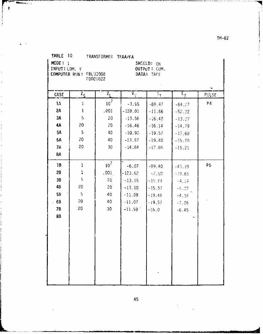
TABLE 10 TRANSFORMER TFAA/FAMODE: I SHELDi ONINPUT: COM. Y OUTPUT* COM.COMPUTER RUN: FBLU3008 DATA* TAPE
F0001822
CASE Z Z V,__ _ Er PULSE
7A 1 107 -3.95 -88.47 -64.,27 P42A 1 .00] -128.01 -11,66 -52.323A 5 20 -13.56 -16.42 -13.274A 20 20 -16.46 -16.14 -14.795A 5 40 -10.90 -19.57 -12.686A 20 40 -13.97 --19.40 -15.787A 20 30 -14.84 -17.88 -15.21
8A
IB 1 107 -6.07 -89.dO -4399 P52B 1 .001. -123.62 -7.5O -'9. 63B 5 20 -13.15 -15 (4 -4.•
4B 20 20 -13.10 -15.57 75B 5 40 -11.09 -19.46 -4.166B 20 40 -11.07 -19.57 -7.067B 20 30 -11.99" -18.0 -6.45
8B
45

TM-82
TABL.E E TRANSFORMER YFAA/FA
MODE: 1 SHIELD: ONINPUT: ,COM. A OUTPUT: cOj.COMPUTER RUN: FRED3006 DATA: TAPE
F0001823
CASE - I. ,, VT IT E-, p-L.•E
IA 1 io7 -10.04 -123.26 -55.15 P42A 1 .001 -89.08 -3.78 -33.893A 20 5 -25.70 -3.93 -3.384A 20 20 -19. 02 -14.04 -2.335A 40 5 -28.55 -8.79 -3.966A 40 20 -21.89 -13.92 -.4.067A 30 20 -20.68 -13.95 -3.19
8A
IB 1 107 -10.15 -12?.0 -56.01 P52B 1 .901 -29.6, - . " -? "3B 20.80 -2. so4B 20 20 -15.5F -13.78 -2.23
5B 40 5 -24.A9 -9.396B 40 20 -17.36 -14.4 -b.407B 30 20 -17.32 -14.45 -276
8B
4F

Th-82
0-
-1015 -4
5 ý_ [T 2 ....VT .,.....,.._.
20-e--_. - - -s
dB -20 -20 5
-30 -
-40.-0 10 20 30 40 50'0
ZL
FIGURE 29 MODE I INPUT Y TRANS. TFAA/FASHIELD ON OUTPUT A PULSE P4
0
4200 ( IT, VT20 40
30 -- -----
dh -20 02 0 -
2 40
-30 - 40
-40 1
0 10 20 30 40 50 00ZL
FIGURE 30 MODE 1 INPUT A TRANS. TFAA/FA,SHIELD ON OUTPUT Y PULSE P4
"47

TM -82
0 - ZL0.
-1 0L40•.~~ ~ o • Z=20
d -20 z C ZL40
-30
,- m m4 0 - -'
0 10 20 30 40 50ZS.
FIGURE 31 MODE 1 INPUT Y TRANS. .'TAA/FASHIELD ON OUTPUT A PULSE P5
0Z ZL=O = =IT, =VT
-!O - z C C
C 20
dB -20 - ZL=20
" ---- Z= 5
-30
-40 -
0 10 20 30 40 50zS
FIGURE 32 MODE I INPUT A TRANS. TFAA/FASHIELD ON OUTPUT Y PULSE P5
48

TM_-82
0-
-10 20 20
dB -20 5 20I
-30 1
i III
-40- L___________________0 10 20 30 40 50 J0
Z L
FIGURE 33 MODE 1 1INPUT Y TRANS. TFAA/FASHIELD ON OUTPUT a PULSE P5
0 1
I.mn T9M-8
20-10 4
402 - - - -----
--30 -
dB -20 40i|ii " "
-4040
0 10 20 30 40 50
~ZL
"FIGURE 34 MODE 1 INPUT A TRANS. TFAA/FA.SHIELD ON OUTPUT Y PULSE P5
49

TM-8i2
TABLE 12 TRANSFORMER TFAA/FAMODE : I SHIELD: OFFINPUT: COM. Y OUTPUT: COM.COMPUTER RUN: A0001652 DATA: INVERSE SHAKER
mCASE ZL ZL VT IT ET PULSE
]A 1 107 -0.26 -121.59 -62.60 P4
2A 1 .001 -.88.01 -9.84 -55.753A 20 30 -7.49 -8.68 -10.094A 5 30 -6.54 -11.25 -12.95
5A
6A
7A
8A
IB 1 107 -2.34 -114.90 -53.93 P5
2B 1 .001. -89.83 -7.34 -41.3?3B 20 30 -7.16 -10.07 -3.414B 5 30 -7.11 -11.25 -4.O,
5B
6B
7B
8B
mIm

TM-82' ,
TABLE 13 TRANSFORMER TFAA/FA
MODE: 1 SHIELD: OFFINPUT: COM. A OUTPUT: COM. yCOMPUTER RUN: A0001656 DATA: INVERSE SHAKER
FBLU3004
CASE ZS ZL V T EI .... PULSE
IA 1 10 -1.43 -113.66 -44.,9 P42A 1 .001 -88.04 25 - 7 .1
3A 30 20 -12.46 - .32 -0.414A 30 5 -21.79 -2.63 -0.47
5A6A
7A
8AIB 1 10-7 3.67 -114.,7 -44.97 P5
2B 1. .001. -89.90 -2.72 -3,-.(,93B 30 20 -10.79 -6.Q1 -0.604B 30 5 -19.47 -3.36 -,".05
5B
6B
7B
8B
51

TM-82• m•
I
50 5
-10 2
- 5/
dB-20 /I
I ,f-30 L73IT CV 7
"-40-10 10 20 30 40 50
ZL
FIGURE 35 MODE I INPUT Y TRANS. TFAA/FASHIELD OFF OUTPUT A PULSE P4
0 1 30 3So - . 30 F •-----4
-10 ---
dB -20 - 3" 0
/-30-
-;I @ = I T , T
-40 - C
0 10 20 30 40 50zL
FIGURE 36 MODE 1 INPUT i TRANS. TFAA/FA
SHIELD OFF OUTPUT Y PULSE P4
52

TM--82
z =
10 - ____ZL__ =i=3
ZL=O
dB -20
-30
T IVT
-400 10 20 30 40 50
zsFIGURE 37 MODE I INPUT Y TRANS. TFAA/FA
SHIELD OFF OUTPUT L PULSE P5
53

TM -82
051
4201_-, - -4 ~
-10
dB -20 /
I 0 1 T IIVT
,:-•.E mTs TM 8
-40- 4
0 10 .20 30 40 50Z L
FIGURE 38 MODE 1 INPUT Y TRANS. TFAA/FASHIELD OFF OUTPUT A PULSE P5
031 30
-4---10 -.
dB -20 - /
I
I
-30 -I
I O :IT [=VT
-40 10 10 20 30 40 50
SZL
FIGURE 39 MODE 1 INPUT A TRANS. TFAA/FA.SHIELD OFF OUTPUT Y PULSE P5
54

TM-82
TABLE 14 TRANSFORMER TFAA/FAMODE: 2 SHIELD: ON
INPUT: COM. Y OUTPUT: COM. ACOMPUTER RUN: ARED3016 DATA: INVERSE SHAKER
ARED3038
CASE z Z VT T ET PULSE
IA 0 107 -5.20 -123.55 -49.51 P4
2A 0 .001 -88.44 -8.95 -38.09
3A 30 20 -19.94 -16.55 -8.46
4A 5 30 -13.1ý -18.83 -3.26
5A
6A
7A8A
1B 0 107 -6.43 -123.65 -49.80 P5
2B 0 .001 -89.45 -8.19 -37.90
3B 30 20 -15.03 -15.75 -4.48
4B 5 30 -12.16 -17.90 -1.80
5B
6B
7B8B
55
iiii___ ____

FM-82
TABLE 15 TRANSFORMER TFAA/FA
MODE: 2 SHIELD: ONINPUT: COM. ,\ OUTPUT: COM. YCOMPUTER RUN: ARED2091 DATA: INVERSE SHAKER
A0003941
CASE Z 5 zL VT IT E ET PULS[
1A 0 107 -9.64 -122.14 -56.20 P4
2A 0 .001 -88.49 -2.02 -31.95
3A 30 20 -21.49 -14.44 -5.09
4A 30 5 -27.76 -9.07 -4.46
5A
6A
7A
8A
1B 0 107 -9.70 -120.74 -56.49 P5
2B 0 .001 -89.45 -1.40 -31.993B 30 20 -17.36 -13.80 -1.574B 30 5 -24.10 -8.73 -2.91
5B
68
7B
8B
56

TM-82
00= =Ts E VT =-T0
-10 --
dB -20 - -,309 5 --30//
-30 /
- 4 0 - 1 - -- " II S
0 10 20 30 40 50ZL
FIGURE 40 MODE 2 INPUT Y TRANS. TFAA/FASHIELD ON OUTPUT A PULSE P4
0 0 30 :IT -] =VT
10-- - -. -
dB -20 - --ý~30
-30 - 30
- 4 0 "0 10 20 30 40 500L
FIGURE 41 MODE 2 INPUT A TRANS. TFAA/FASHIELD ON OUTPUT Y PULSE P4
57

TM-82
01
-10 oI , - 5
dB-2 --- - 30 -- .-\ ,d B - 2 0 - 5" - -./b
//
-30-
-40-,
0 10 20 30 4C 50 J
FISURE 42 MODE 2 INPUT Y TRANS. TFAA/FASHIELD ON OUTPUT A PULSE P5
0-0=IT,'
=VT
-10 -
dB -20 -0
/-30 /
-40]'
0 10 20 30 40 50ZL
FIGURE 43 MODE 2 INPUT A TRANS. TFAA/FASHIELD ON OUTPUT Y PULSE P5
58

TM-82
TABLE 16 TRANSFORMER TFAA/FAMODE: 2 SHIELD: OFFINPUT: COM. Y OUTPUT' COM, ACOMPUTEk RUN : FBLU3006 DATA: TAPE
CASE Z . Z T IT E T PULSE
IA 0 107 -0.04 -115.44 -42.26 P4
2A 0 .001 -88.50 -6.33 -38.50
3A 20 30 -7.62 -7.82 -0.284A 5 30 -6.31 -10.24 -- 1.105A
6A
7A
8A
B 0 10 7 -2.21 -116.80 -50.77 P5
2B 0 .001 -89.76 -6.58 -38.9738 20 30 -6.69 -10.01 -0.454B 5 30 -7.77 -12.16 -1.67
5B
6B
7B
8B
59

TM-82
TABLE 17 TRANSFORMER TFAA/FA
MODE : 2 SHIELD: OFFINPUT: COM. OUTPUT: COM. YCOMPUTER RUN: FBLU3005 DATA: TAPE
CASE z S_ L VT T E T 'L[7 V 7
IA 0 107 -2.19 -113.24 -4..;/. 8 P4
2A 0 .001 -88.50 -2.67 -37.26
3A 30 20 -11.02 -4.23 -0.45
4A 30 -21.13 -2.26 -1.75
5A
6A
7A
1B 0 107 -4.22 -114.73 -51.77 P5
2B 0 .001 -89.76 -2.71 37.66
3B 30 20 -10.40 -6.44 -0.78,4B 30 5 -i9.56 -4.31 -2.4")
5B
6B
7B
8B
60

TM- 82
0
0
0 -=. .-. ..-
5 . ..- - '--10 --- "ý "
/
dB -20i ~II
-30
0 10 20 30 40 50ZL
FIGURE 44 MODE 2 INPUT Y TRANS. TFAA/FA
SHIELD OFF OUTPUT 6 PULSE P4
0 o -• _ .-
-10
dB -20 /30
-30- II
-40 + r c .I I I . .0 10 20 30 40 50 00
ZL
FIGURE 45 MODE 2 INPUT A TRANS. TFAA/FASHIELD OFF OUTPUT Y PULSE P4
61

TM-.82
0 -'ZL= LOo0 Z L 00
94 ] Z L = 3 2-10 L
dB -20
-30
-40 10 10 20 30 40 50
zSF!GURE 46 MODE 2 INPUT Y TRANS. TFAA/FA
SHIELD OFF OUTPUT A PULSE P5
62

TM-82
02ilii~0 o 0n-10. -- 0
5
dB -20 /IfI
-30-l= E =oS
•. ~~-404 -w
0 10 20 30 40 50z,
L
FIGURE 47 MODE 2 INPUT Y TRANS. TFAA/FASHIELD OFF OUTPUT nk PULSE P5
0
dB-10 /30-
IIII
II 0 T' CV T
e I I I0 10 20 30 40 50 00
zlL
FIGURE 48 MODE 2 INPUT .6 TRANS. TFAA/FASHIELD OFF OUTPUT Y PULSE P5
63
=mta&

TM-82
TABLE 18 TRANSFORMER TFAA/FA
MODE: 3 SHIELD: ONINPUT: COM. Y OUTPUT: DIF.COMPUTER RUN: F0001820 DATA! TAPE
ARED2092
CASE Z ZL VT T E _T PULSE
IA 1 107 -18.88 -141.94 -74.17 P4
2A 1 .001 -113.87 -36.92 -78.113A 20 5 -45.98 -32.59 -38.534A 20 20 -36.83 -35.47 -34.78
"5A 40 5 -47.11 -32.18 -38.286A 40 20 -37.04 -35.04 -34.73
7A
8A
B 1 107 -23.53 -140.27 -73.40 P5
2B 1 .001 -113.79 -30.53 -64.80
38 20 5 -41.47 -30.41 -30.194B 20 20 -31.24 -32.22 -27.05
5B 40 5 -40.78 -30.2" -30.51
6B 40 20 -30.72 -32.22 -28.31
7B
8B
L
Ri64

TM-82
TABLE 19 TRANSFORMER IFAA/FA
MODE: 3 SHIELD: ONINPUT:DIF. OUIPUT: COM. YCOMPUTER RUN: F0001821 DATA: TAPE
F0003387
CASE Z __ZL VT I ET - PULSEL T T T
IA 1 107 -29.11 -151.12 -94.86 P42A 1 .001 -113.40 -35.41 -76.133A 5 20 -35.09 -36.13 -39.774A 20 20 -37.90 -33.78 36.385A 5 40 -33.02 -40.08 -40.216A 20 40 -35.80 -37.70 -37.03
7A
8A
18 1 107 -29.01 -141.21 -79.45 P52B 1 .001 -113.80 -26.01 --60.p033 5 20 -35.01 -31.52 -28.954B 20 20 -34.52 -29.78 -28 .C385B 5 40 -32.35 -34.88 -29.1,,'6b 20 40 -32.03 33.31 -29.247B
6B
65

"TM-82
-10= T' :IT,=V T
-20
dB -30 - 40 20,
'20 40
-40 2- -2 .. .-5040 0,
2
4 0-50
0 10 20 30 40 50Z L
FIGURE 49 MODE 3 INPUT Y TRANS. TFAA/FA.SHIELD ON OUTPUT A PULSE P4
-10®:.IT,.VT
-20 -
dB -30 -0 5 5
12 -4
-40 - 20
5oo
0 10 20 30 40 c0ZL
FIGURE 50 MODE 3 INPUT A TRANS. TFAA/FASHIELD ON OUTPUT Y PULSE P4
66

TM-82
-10
-200_I ZL::
dB -30 - .,ZL O ._.- ZL= 5
, =40I-.
-40 -ZL= 5
-50 "Li 'i . .ri
0 lo 20 30 40 50zS
FIGURE 51 MODE 3 INPUT Y TRANS. 'FAA/FASHIELD ON OUTPUT A PULSE P5
-10= =IT, ( =VT
-20ZL-=O
dB -30 -ZL= ZL=20--.-.j ""Z L=40
- 4 0 -
a50- I I0 10 20 30 40 50
zS
FIGURE 52 MODE 3 INPUT A TRANS. TFAAiFASHIELD ON OUTPUT y PULSE P5
67

TM-82
Tl T
-20o =IT, 0n VT
-20
1
40----
0-
4 0
5
0 10 20 30 40 50"I
ZL
FIGURE 53 MODE 3 INPUT Y TRANS. TFAA/FASHIELD ON OUTPUT A PULSE P5
-10O=IT9 m =VT
-20
20 2020dB -30- 5
50 -42
-40 100-
/fI I I ..
0 10 20 30 40 50 00ZL
FIGURE 54 MODE 3 !NPUT A TRANS. TFAA/FASHIELD ON UUTPUT y PULSE P5
68

TM- 82
TABLE 20 TRANSFORMER TFl004
MODE: i SHIELD: ONINPUT: COM. Y OUT-PUT: CON. ACOMPUTER RUN: F000339P DATA: TAPE
CASE Z V I P_ T T. - - _LS
1 -16.06 -138.52 -81.98
2A 1 .001 -97.97 -20.24 -65.81
3A 10 20 -26.17 -24.81 -21.704A 30 20 -29.60 -25.00T-23.
5A 10 40 -24.13 -28.80 ý22.50
6A 30 40 -26.85 -28.27 -23.48
7A 10 0 -760.0 -i6.09 -380.08A 30 30 -27.87 -26.80 -23.43
1B 1 107 -16.79 -132.95 -67.42 P5
2B 1 .001 -98.49 -14.24 -50.24
3B 10 20 -23.30 -23.30 -15.35
4B 30 20 -23.78 -22.60 -17.53
5B 10 40 -20.94 -22.96 -16.37
6B 30 40 -21.52 -26.33 -18.10
7B 10 0 -760.0 -14.87 -380.0
8B 30 30 -22.33 -24.66 -17.80
69

TM-82
TABLE 21 TRANSFORMER TF1004
MODE: 1 SHIELD: ONINPUT: COM. A OUTPUT: COM, yCOMPUTER RUN: F0003397 DATA: TAPE
CASE ZS ZL VT IT ET PULSE
IA 1 107 -17.78 -133.09 -66.39 P42A 1 .001 -98.47 -13.63 -46.933A 20 10 -32.47 -21.66 -16.674A 20 30 -28.21 -26.93 -17.37
5A 40 10 -35.76 -21.85 -19.156A 40 30 -30.79 -26.41 --19.097A 0 10 -24.32 -19.94 -13.398A 30 30 -29.64 -26.62 -18.33
713 1 10 -16.40 *131.5? -66.6q P52B 1 .001 98.43 -1 J.LA -46.1638 20 10 -29,07 -20.8F, -13.95
4B 20 30 -22.85 -25.?l -15.0c
5B 40 10 -29.59 -21.03 -15.u96B 40 30 -24.44 .25.43 .-15.707B 0 10 -24.09 -19.22 -12.748p 30 30 -23.83 -25.34 -15.40
70

TM-82
0 0--T, UJVT
1
dB -20 -,"30 10
-3 301/
0 10 20 30 40 50ZL
F.GUR':F 55 Mr.)E I INFUT Y TlANtS. TFIO04STJLLD ON OJIU'P(Jl A PULSi P4
(I --
dii - 2) -
20,40 --- - - -20,30,40
-I
40
0 201 30 40zL
FI1UPE 56 MODE 1 INPUT A l[J~S, TF1004SIJ,] i D ON OUTr'UT 11[. ''-1 P4

TM-82
0 0 0
I~~ Z I , =40-V..B, - 2 0 "m .ZLO 0
-0 -L= 40
nI ~~-40-
1 ZS_75
iF c.R E 57 MOD[ I YI t Y TRA1S, TF1004S1;,1 Ell' ON Uli 1, A PULSE P5
1( .- ' '1I ,
-10 -
Z L 0
(lB -L -- 0
o o ZL= 30
.-40 -1 0 2 t • .4 0 ,•
F-1 Y["1 58 TFIS rr A TI/hS, IF1004S!II [,F ON OUTPUT Y FHL. P5
72

TM-82
0O=IT, 9 -VTI ~-10-
10 10db -20 3
- 30 3
/0-30 /100
/
-40 -7 .f'I -- -
/I T Ii C
"0 20 30 40 50z L
MIGI;pi, 59 m0Du I INPUT Y T ,A ,,S. TF1004SH] LL) ON OUTPUT A PIUL SE P5
-10 --
40d lS - ? .r 3 0-
03-0 20 3-
-.3 / Z 40 301 0
0 10 20 30 40'L
FiGu:,E 60 MODE 1 INPUT 'A TRANS. TF1004SHI Ll.1) ON OUTPUT Y PULSE-. P7
73

TM-82
TABLE 22 TRANSFORMER TF1004
MODE: 2 SHIELD: ONINPUT: COM. y OUTPUT* COM.COMPUTER RUN: F0003389 DATA: TAPE
CASE Z zL .... V •TT PULSE
IA 0 ]07 -17.62 -133.71 -65.67 P4
2A 0 .001 -99.82 -15.89 -50.243A 10 20 -27.16 -24.64 -I%?254A 30 20 -31.42 -25.05 -18.055A 10 40 -25.38 -28.86 -15.946A 30 40 -28.84 -28.50 -18.75
7A 10 0 -760.0 -16.46 -380.08A 30 30 -29.78 -26.94 -18.33
oB 0 107 -16.65 --132.08 -65.92 P5
2B 0 .001 -99.94 -15.30 -49.94
38 10 20 -22.05 -23.42 -14.254B 30 20 -25.04 -23.75 -14.97
5B 10 40 -19.68 -27.04 -14.97
6B 30 40 -22.78 -27.43 -15.7478 10 0 -760.0 -15.99 -380.0
8B 30 30 -23.60 -25.81 -15.3
74

TM-82
TABLE 23 TRANSFORMER TF1004
MODE: ? SHIELD: ONINPUT: COM. OUTPUT: COM. YCOMPUTER RUH: F0003388 DATA: TAPE
CASE 7s z L V T I- E ET PULSEIA O 107 -17.74 -132.89 -67.78 P4
2A 0 .001 -99.82 -15.07 -48.77
3A 20 10 -32.59 -21.63 -17.044A 20 30 -28.40 -26.97 -18.43
5A 40 10 -36.15 -22.17 -19.07
6A 40 30 -31.18 -26.73 -20.487A 0 10 -24.78 -20.00 -15.02
8A 30 30 -29.96 -26.83 -19.50
IB 0 107 -17.32 -132.12 -67.74 P5
28 0 .001 -99.94 -14.78 -48.37
3B 20 10 -27.79 -20.28 -14.984B 20 30 -23.11 -25.14 -16.34
5B 40 10 -29.33 -20.52 -15.66
6B 40 30 -24.75 -25.50 -17.077B 0 10 -24.60 -19.43 -14.59
8B 30 30 -24.13 -25.36 -16.71
/ J

TM-82
0eIIT, =VT
-10
10 0
dB -20
-300
d0e - 30 30
-40-- . ............... o.
0 10 20 30 40 0 07
ZL
FIGURE 61 MODE 2 INPUT Y TRANS. TF1004SHIELD ON OUTPUT A PULSE P4
0
-10~'
0dB -20- 0
4 40• 30
40 20.
-40 - i-r T--"4
0 10 20 30 40 50 oZL
FIGURL 62 MO:_ E 2 1,'PUT A TPANS. TF1004
.%!:11LD ON OUT!'UT Y PUI.L P4
76

TM-82
0= IT, o=VT
ZL=0
S~d3 -20 - L .4d3Z =40
~z = 20I o ZL= 4 0
i i i -30 - ,
i ~~~-40- I II
0 10 20 30 40z S
FIGURE 63 MODE 2 INPUT Y TRANS. TF1004SHIELD ON OUTPUT A PU LSL P5
0IT ED VT
I -~- , lo --
ZL 0L=
dB -z0 -e O ZL=1OI•I•~ __0• ] ZL=: 30
-3 0 -J Z L 0L=
-40 o
i. 10 20 30 40 5I I S
FIGURE 64 MODE 2 INIUT A TRA NS) TF IJotSH 1I. LD ON OU 'Tfp r Y PULSI1 P5
• -- I/1

TM-82
0
-00 10
dB 20 - •I ,30 -.64--
! -20 30100 30 !." " ý ---
-30 30
I,Ii
0 40 1 0 ý O i c0 4 0 r , ,7
L
FIGi 65 ,ODE 2 1W11'1f Y IPP, NS. TFIO040 SHI ILLD ON OU 1- UT JT PUA ½,L P5
O-0o -- IT .: VT
20 040
cm -20-20
200
-40 ,40
C0 10 20 30 ,oZL
FJC uoi'F 66 flou[ 2 INIPUT A TIIAN(.t TF1004S!I LLD ON OIUT[,'I Y PUL([ P5
7P.

TM-82
TABLE 24 TRANSFORMER TF1004
MODE: EQUIVALENT TO MODE 2 SHIELD: ONINPUT: COM. LA EQUIVALENT OUTPUT: COM. Y EQUIVALENTCOMPUTER RUN: A0001659 DATA: SHAKER
A0001661
CASE Z VT ET PULSE
IA 1 107 -20.99 -140.90 -52.57 P4
2A 1 .001 -96.43 -16.48 -40.44
3A 0 10 -22.33 -26.80 -10.814A 20 10 -30.27 -20.90 -2.44
5A• 6A
7A
8A
IB 1 107 -19.83 -143.40 -58.88 P51 .Ol -92.80 -16.48 -43.45
38 0 10 -22.33 -26.80 -10.814B 20 10 -27.18 -23.29 +1.19
5B 20 5 -30.39 -20.48 +1.92
6B 20 25 -23.85 -27.90 +0.907B 20 40 -22.76 -30.88 +0.91
8B 20 .001 -100.35 -16.48 -31.52
79

TM-82
0-0 :IT,EN VT
-10
dB ,-20 0- 0 *
"�"-�-4
-30 0 -1•" 20
/
0 10 20 30 40 5 0- 'ZL
FIGUR.E 67 MODE 2 INPUT A TRANS, P11004SHII EL.l ON OUTPUT Y PUI SE P4
80

' .T M -8 2
0N ~ i "• -I T , U =v1
dB -20 -GZL= 0ZL=I0
L :
-40 i0 I 0 0( [ 40 50
FIflL'71 68 Mt'O)r 2 ] NitlIT T.",AN N- Pi1104SW [LD ON OUTPUT Y PUL SE P5
'I
TM-82iA
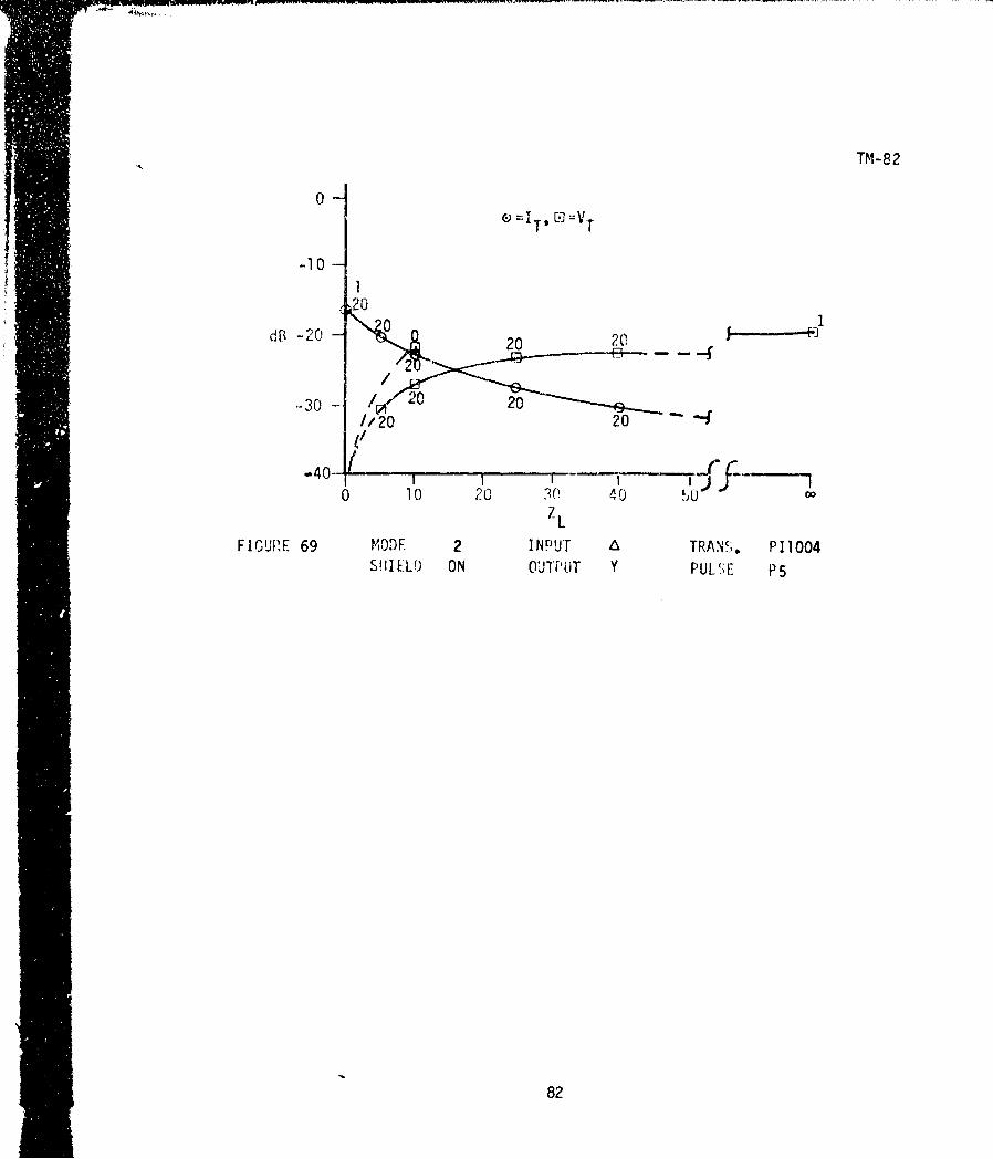
0
I'T' [- VT
-10 1
20
dB -20 0 20 20.-2O
,-30 20//lz20 20 -4
-40 10 20 30 40 5 00
FIGURE 69 MODE 2 INPUT A TRANS. P11004S! IIELU) ON OUTPUT Y PUL[E P5
82

TM-82
TABLE 25 TRANSFORMER TF10O
MODE: I SHIELD: ONINPUT: COM. Y OUTPUT: COM. -ACOMPUTER RUN: *ARED5066 DATA: *INVERSE SHAKER
F0003396 TAPE
CASE zs z vE I PULSE
IA 1 107 -5.99 -127.89 -73.61 P4
2A 1 .001 -94.38 -16.4( -66.04
3A 20 20 -20.40 -15.36 -15.594A 20 40 -17.61 -18.4S -15.17
5A 40" 20 -23.52 -16.08 -16.66
6A 40 40 -20.74 -19.25 -16.-07
7A 30 30 -20.45 -17.44 -15.45
8A
IB 1 107 -5.98 -120.25 -57.25 P5
2B 1 .001 -94.37 -9.31 -48.73
3B L0 20 -16.35 -14.62 -8.764B 20 40 -13.16 -17.51 -8.25
5B 40 20 -181.7 -15.58 -10.156B 40 40 -15.44 -18.44 -9.497B 30 30 -15.60 -16.72 -9.078B* 20 2.5 -29.43 -6.60 -20.549B* 20 5 -23.95 -6.63 -20.83
lob* 20 10 -21.02 -7.77 -27.4311B* 20 50 -10.pq -17.23 --9.07
12B* 5 20 -13.44 -10.58 -0.0313B* 20 .001 -92.46 -8.99 -41.48
144B* 20 40 -11.70 -16.34 -8.86
83

TM-82
TABLE 26 TRANSFORMER TF10O
MODE: ' SHIELD: ONINPUT: COM. A OUTPUT: COM. YCOMPUTER RUN: F0003394 DATA: TAPE
F0003395
CASE S ZL VT LT ...... __T PULSE
IA 1 107 -13.06 -121.29 -57.20 P4
2A 1 .001 -94.72 -3.55 -43.27
3A 20 20 -20.82 -12.07 -6.76
4A 40 20 -24.06 -12.75 -6.80
5A 20 40 -19.11 -16.26 -7.28
6A 40 40 -22.39 -16.99 -7.08
7A 30 30 -21.49 -14.7 -6.92
8A
71B 1 10 -12.43 -121.49 -57.39 P5
2B 1 .001 -94.28 -3.96 -43.023B 20 20 -17.03 -12.36 -6.48
4B 40 20 -18.15 12.61 -6.44
5B 20 40 -15.10 -16.43 -7.01
6B 40 40 -16.21 -16.72 -6.737B 30 30 -16.36 -14.74 -6.60
&B
84

TM-82
0 O-o e=IT$ c-VT
2-1 -
020d * --20 -
40
40
-30-- /#I
-.40- -- I )
0 10 20 30 40 50ZL
FIGURE 70 MODE 1 INPLUT y TR,.N- N TF1010SHILLD ON OUTPUT & PUl.S p4
0 - 1 m =V
-10 - -.. 20
d5 -20 20 20
""-4,---
-30 1/
0 10 20 30 40"•
zL
FIGURE 71 MODE 1 INPUT A TRANS. TF10O
SHILLD ON OUTPUT Y PULSE P4
85

TM-82
Z L: -,1 =eIT' -i. V T
0 -ZL ' SHAKER DATA zL=20Z Z L =40
d0, -20ZL =40
-30
0 10 20 30 40 50z s
FIGURE 72 MODE I INPUT Y TRANS. TF1010SHIELD ON OUTPUT A PULSL P5
0,sz C 0 C.( 11. Ll --
10-O -L. - ZL :. 2 0
dR -20 -ZL=40
ZL: 20
-30
-40 T -
0 10 20 30 40 50zs
FIGURE 73 MODE 1 INPUT A TRANS. TFI010SHIELD ON 0Ul rU r Y PULSE P5
86

0 0 T'0
-- o 2(f " 20 20di-40O. 30
--3 12?
*SHAKER DATA
"o 10 20 30 40ZL
FIGURE 74 MODE 1 N "UT Y TRANS. TF10OSHI[LD ON OUTPUT a PULSE P5
0-"1 -T,> [. =VT
NT
-10 -1l - -" . 20 2
20 -20
d.13 -2L' -3
//
-30 - /
I
-40 - F,1 20 30 40 50 CI
ZL
FIGURE 75 MODE 1 INPUT a TRANS. TF1O10SHIELD ON OUTPUT Y PULSE P5
87

Th-82
YBLE 27 TRANSFORMER TF1U1O
MODE: 2 SHIELD: ONINPUT: COM. y OUTPUT: COM. ,COMPUTER RUN: A0001651 DATAM INVERSE SHAKER
CASE ... VII'I E T PULSE
IA 0 10 -.7.23 -120.01 -53.58
2ý 0 .001 -95.17 -7.57 -44.733A 30 30 -20.85 -16.24 -9.234 A5A
6A
7A
SA
1B 0 107 -5.97 -118.30 -52.C6 P52P. 0 .001 -94.58 -7.20 -43.1533 30 30 -15.03 -15.76 -0.974B
55
7B
8B
86

TM-82
TABLE 28 TRAN 3 FORMER TFIO1O
MODE: 2 SHIELD: ONINPUT: COM. . OUTPUT : COM. YCOMPUTER RUN: ARED3018 DATA. INVERSE SHAKER
CASE Z ZL V I ET PULSE.
IA 0 107 -11.27 -120.28 -61.11 P4
2A 0 .001 -94.50 -3.37 -44.17
3A 30 30 -20.21 -11.54 -9.954A5A
6A
7A
8A
IB 1017 -10.61 -121.00 -61.03 P52B 0 .001 -94.53 -4 10 -43.493B 30 30 -14,92 -12.58 -8.094B
5B
6B
7B
8B
89

.. . . . . .. . . . . .. . . . . ........
TM-82
03
-10-40
-0 1- 20 30 40 5 0
dB -20,,,,
-10 - 30
-300-30 -
//
-40 -
0 10 20 30 40 50 00
ZLFIGURE 76 MODE 2 INPUT a TRANS. TF1O0O
SHIELD ON OUTPUT Y PULSE P4
S0 -
-10- - ® OIT~, EB:VT---2 0-" 300
i-30 /3
S~/
/
"o 1I0 20 30 40 $
ZLjFIGURE 77 tHODE 2 INPUT ,•TRANS. TF1O1O
SSHIELD ,ON4 OUTPUT V PUI.SE P4
ig

TM-82
0eI.l =VT 0
o
-10 --- 30
-/
-30 /
S-30 - / ,iyl -'
0 10 20 3 40- L
o]3')' E 78 D 2 INPUIT Y I Pf I .S TF1O1O
SHIELD ON OUTPLfl A PUI AL P5
0-O =IT.~V
$ .. " 10stj,"
-10- 30
//
-30- /I
-40 -
1) 20 30 40ZL
FIGURE 79 MODE 2 INPUT A TRANS. TF1010
SHIELD ON OUi PUIT Y PUISI P5
91

TM-82
TABLE 29 TRANSFORMER TF10O
MODE: 5 SHIELD:. ONINPLT: DIF. Y OUTPUT: DIF. ACOMPUTER RUN: F0003427 DATA: TAPE
CASE Z zL VT T ET PULSE
IA 1 17 -0.35 -121.03 -54.97 P2A 1 .001 -109.26 -29.70 -67.633A 30 30 -22.90 -18.59 -4.38
4A
5A
6A
7A
8A
I 1 i0 -14.24 -125.26 -49.65 P52B 1 .001 -120.39 -31.32 -64.653B 30 30 -31.77 -29.52 -12.884B
5B
6B7B
8B
92

-n-- -l
TM-82
TABLE 30 TRANSFORMER TF1010
MODE : 5 SHIELD: ONINPUT: DIF. O~JTPUT: DIF. YCOMPUTER RUN: vARED5067 DATA* *INVERSE SHAKER
F0003426 TAPE
CASE Z, z VT I E-1
- - __L____T I PULSE
1 A 1 10 -2.93 -123.29 -61.03 P
2A 1 .001 -109.92 -29.25 -67.75
3A 30 30 -23.01 -17.73 -5.96
4A
5A
6A7A
83A
18 1 10 -14.94 -124.46 -53.0Aq P52B 1 .001 -120.25 -29.70 -65.03
3B 30 30 -30.46 -28.38 -13.3548* 30 2.5 -54.50 -26.60 -33.86
58* 30 5 -48.62 -26.58 -30.09
6B* 30 10 -42.55 -26.80 -25.797 D I f 50 -27.98 -23.69 -12.65
88k 30 .001 .121.79 -26.09 -68.609B* 30 30 -31.90 -23.91 -17.25
93

TM-82
0 o~T' i*T
-10
30 -
dB -20 -
- - 30
-30- J
-.40-/
0 10 20 30 40 50
FIGURE 80 VMODE 5 I NPUT y TRANS. TF 1010SHI-1LD ON OUTPUT A PUVr P4
0= 0-T9 CD=V T
-10
30 -
dB -20 - -
-30 -- -- 3
' .i- I 3 0
0 0 3 0 50 0Z L
FIGURE 81 MODE 5 I NPUT a TRANS. TF1010SHIELD ON OUTPUT Y PULSE P4
94

TM-82
-10
dL -23
30
-30 130
- 30
0 10 20 30 40 (00Z L
FIGURF, 82 MODE 5 1lP UT Y TRANS. TF1O1OSP-iELD ON OUTIPU'" A PULSNE P5
-20 3
dB -4)
3 T1T =V T *SHAKER DATA
0 10 20 30 40 50 0ZL
FIGURE 83 MODE 5 INPUT A TRAN';. TF1010SH1IELD ON OUTPUT Y PUL'Z P5
95

TM-82
TABLE 31 TRANSFORMER CONTROL
MODE: 1A SHIELD:INPUT: COM. 480V OUTPUT: DIF. 120VCOMPUTER RUN: FC003392 DATA: TAPE
F0003432
CASE ZS ZL VT T E T PULSE
IA I 107 -5.88 -106.83 -45.08 P42A 1 .001 -108.68 -10.28 -54.853A 30 5 -35.77 -10.05 -18.744A 30 15 -26.50 -10.30 -14.4i5A 30 30 -21.04 -10.84 -12.076A 30 107 -6.60 -106.63 -44.887A 30 .001 -109.66 -9.98 -55.518A
11 1 107 -5.3? -107.72 -41.31 P52B 1 .001 -108.59 -11.10 -49.703B 30 5 -34./6 -10.24 -13.564B 30 15 -25.54 -10.53 -9.42
5B 30 30 -19.65 -10.63 -7.316B 30 10 -5.12 -106.57 -41.057B 30 .001 '-108.47 -9.98 -50.248B 30 104 -5.13 -46.59 -11.959B 30 103 -5.63 -27.17 -6.27
lOB 30 102 -11.30 -12.69 -5.3111B 1 104 -5.37 -47.77 -12.1912B 1 102 -1.Z.b4 -14.90 -4.9U
96

TM82
TABLE 32 TRANSFORMER CONTROL
MODE: 2A SHIELD:INPUT: DIF. 480V OUTPUT: DIF. 120VCOMPUTER RUN: F0003393 DATA: TAPE
F0003433
CASE Z ZV T IT ET PULSE
1A 1 107 -2.91 -121.45 -69.10 P4
2A 1 .001 -107.54 -26.31 -72.983A 50 5 -35.86 -7.03 -18.874A 50 15 -26.49 -7.12 -14.325A 50V 30 -20.56 -7.11 -11.95
6A 50 10 -2.87 -98.92 -51J.737A 50 .001 -109.86 -7.09 -5.5.87
8A
IB 1 107 -3.79 -105.98 -52.63 P52B 1 .001 -106.65 -9.32 -60.553B 50 5 -31.41 -2.06 -11.994B 50 15 -22.16 -2.00 -7.695B 50 30 r16.92 -2.29 -5.3E6B 50 107 -3.02 -98.06 -38.547B 50 .001 -105.34 -2.17 -48.748B 50 104 -3.05 -38.10 -9.359B 50 103 -3.79 -18.92 -3.31
lOB 50 102 -10.61 -5.81 -2.70llB 1 102 -10.51 -12.78 -14.1312B 1 10 -3.84 -46.03 -23.15
97

TM-82
0~ 1.' T V
-10 030 0L 30
d!3 -20--4
- 03 0
30
-30
-400
0 10 20 30 40 50 00ZI.
F IL'aURE 84 MODE ]A INPUT COM. 480V TRANS4, CONTROLSHIELD OUTPUT 01FF 120V PULSE P4
0 50
550
-30 50
0 0 20T 30V 40 so0 Cf.z L
FIGURE 85 MODE 2A INPUT D1FF 48OVTRANS. CONTROLSHIELD OUTPUT COM. 1 20VPULSE P4
98

TM-82
0 0 = 1 T ' C -1 = V T 3
-0 30 30 30 301
dB -20 -ll`111r ý
-300
0 10 20 30 40510Z L
F IGURE 86 MODE IA I NPUT COM 480V TRANS. CONTROLSHIELD OUTPUT DIFF 120V PULSE P5
0O 050 0O 50E- - 50
dB3 -20 5
-30-
-4050
O4 10 20 30 40 50 0Z L
FIGURE 87 MODE 2A INJPUT DIFF480%# TRANS. CONTROLSHIELD OUTPUT D IFF 120V PULSE P5
99

TM-82
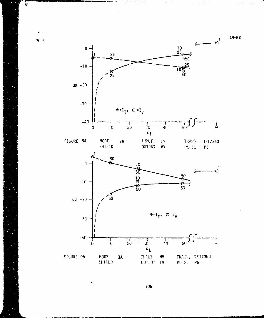
TABLE 33 TRANSFORMER T17363MODE: 3A SHIELD:INPUT: COM. LV WINDING OUTPUT. COM. HV WINDINGCOMPUTER RUN: F0003423 DATA: TAPE
CASE Zr ZL VT I'T E PULSE
IA 107 +4.12 -112.91 -39.54 P4
2A 1 .001 -87.73 -4.50 -41.323A io 50 -2.86 -10 12 -1.334A 25 50 -3.54 -8.64 -0.765A 50 50 -7.25 -8.90 -0.746A 25 10 -13.00 -4.10 -4.59
7A8A
1B 1 107 +2.72 -113.56 -47.29 P52B 1 .001 -90.22 -5.51 -40.67
3B 10 50 -3.42 -11.59 -0.994B 25 50 -3.80 -10.6,' +1.05
5B 50 50 -6.08 -12.03 +22156B 25 i0 -12.70 -5.68 -3.75
78
8B
IC 1 107 -3.50 -116.14 -52.01 PI2C 1 .001 -98.40 -9.93 -44.603C 10 50 -11.81 -16.49 -4.884C 25 50 -12.72 -16.61 -3.875C 50 50 -15,40 -18.96 -3.686C 25 10 -22.74 -12.50 -7.27
I 00

TM-82
TABLE 34 TRNASFORMER T17363
MODE: 3A SHIELD:INPUT: COM. HV WINDING OUTPUT: COM. LV WINDINGCOMFUTER RUN: F0003422 DATA: TAPE
CASE 7 z V. IT c PULSE
1A 1 107 -0.74 -107.73 -43.44 P42A 1 .001 -87.88 +L.83 -40.503A 50 10 -13.89 +1.44 -4.844A 50 25 -8.68 -1.09 -2.405A 50 50 -7.87 -6.17 -0.866A 10 25 -6.45 -1.56 -2.767A
8A
B 1 107 -3.93 .-108.79 -50.27 P5
1B 1 .001 -90.27 +3.96 -39.0338 50 10 -16.27 +0.51 -3.844B 50 25 -11.56 -2.66 -1.205B 50 50 -10.85 -8.67 +2.486B 10 25 -9.75 -2.12 -2.427B
8B
iC 1 107 -14.36 -115.9, -53.39 Pl2C 1 .001 -98.19 +0.78 -38.883C 50 10 -24.42 -5.59 -6.154C 50 25 -19.83 -8.95 -4.545C 50 50 -19.29 -14.88 -3.536C 10 25 -18.68 -8.89 -4.25
101

TM-82
0 0 ,-IT , E=VT
--10 225 10
dB -20 ..102.25
25 50
-30 /.C I
( 10 20 30 40 50z ZL
FIGURE 88 MODE 3A ItNPUr LV TRANS. TF17363SHIELD oUTrPUT HV PUL, F. pI
050 11, ,rJ=VT
10n10 -- 50"
10dq, -2[95
-5 50
-30 -- /I
II I -40 r• r
0 10 20 30 40 '.)ZL
FIGURE 89 moll)F 3A ItNPUT HV IRANS. TF17363SHIE I. IT OTPUT LV PtJLSL. P1
102

, 7 TM-82
0 1
-10 5
' 50
dBiO /dB --20-
/I
-30S=I T,9 (D VT
-40-- T LF.i ...
0 10 20 30 40ZL
FIGURE 90 MODE 3A INPUT LV TRANS. TF17363SHIELD OUTPUT HV PUL ,E P4
1 1
010 50,
-10 50 50 "r0-
-100
d0 -20 /III
-30I eT' M=VT
"-40 -
0 10 20 30 40ZL
FIGURE 91 MODE 3A I NPUT HV TRANS. TF17363SHILLD OUTPUT LV PULSE P4
103

z TMt-82
S=ZL=5"-"
3 ZL =5O
dB -20 -
-30 -
0 10 20 30 40 5(;ZS
FIGURE 92 MODE 3A INPUT LV TRANS. TF17363SHIELD OUI PUT HV PULSE P5
®ZL=O0- ZL25
-ZL =-10 -r -ZL :2 "S
dB -20 -
-30 -r)l I =VT
-40 ?l I ,0 10 20 30 40 50
zsFIGURE 93 MODE 3A INPUT HV TRANS. TF17363
SHIELD OUTPUT LV PULSE P5
104
i A,, ] TM-82
0 10125 22
-10 2r
/25 50__ / '
I
-30 ISI G=IT, 0 '•v
0 = T v ( rj v • - ' - - -
0 1 20 3C 40 50ZL
FIGURE 94 MODE 3A I N"UT LV TRAT'I, TF17363SHIEI.D OUl PUT HV PUI. I. p
500 10
50S-I0 10F1
.; ý 50 50
dB -20- / 50~/
i _T
iI-
-4r -
0 10 20 30 4, b
ZLFIGURE 95 MODE. 3A T1P UT HV TRA!:s. TF17363
-HI.-kP OUTPUT LV PUl SC P5
105

"TM-82
TABLE 35 REGULATOR
MODE: 4A FOOST SHIELD:INPUT: 1 OUTPUT: 2COMPUTER RUN: FBLIJ6080, DATA* TAPE
FRED7035
CASE Z- ZL V T IT ET PULSE
3A 1 10 7 .28 119.53 -7'8.6• P4
4A 50 107 -71. 97.75 -45.13
5A 10 10 -14.53 -4.77 2.36
6A I0 50 -5.32 10.22 -2.637A 1 50 -4.18 -21. 958A 100 5'-' -6.66 -3.4i -.0.6!
')A 50 3 27.98 .2.42 -4.69
I0A 50 10 -18.11 -3.11 -P.49
11A 50 20 --12.79 -3.88 -1.7412A 50 50 -6.51 :.41 -0.91
13A 100 I -2.9i -7.20 11
14A luO 10 -18.81 -2.06
17A 1 1 -26.58 9.44 -'"Y.
18A 50 1 -37.17 -2.03 -7.79
NOTE CASE 1A, 2A, 15A and 16A are void.
106

TM-82
TABLE 35 (Cont.) REGULATOR
MODE: 4A 'COST SHIELD:INPUT: I OUTPUT: 2COMPUTER RUN: FBLU6081, DATA* TA E
FBLU6101,FRED7035
CASE Z Z V T E PULSE
3B 1 107 -2.34 -114.05 -49.52 P5
4b 50 107 0.66 -106.15 -37.33
5b 10 10 -22.47 -13.16 -4.946B 10 50 -11.23 -15.65 -3.14
179 50 -12.60 -18.64 -F.1O
1B 100 ' -10.02 -I0.55 ,2.7(,
1 50 3 32.24 10.39 -1C.14
1CA 50 it -22.18 -10.75 6.'9
1 FI 50 2 U -16.70 -1!.19 0 .31
128 5C 50 -10.23 -12.37 -2.70
131' 50 10() -6.3r -14.12 -l.)7
14': 100 10 -22.03 -9.08 -F-71
17B I 1.. 40.99 12.96 -0.1
18C 50 1 -41.61 -10.24 -14.45
TJ0TE: CASE 1B, 2B, 15B ard 16B are void.
1 07

TM-82
TABLE 36 REGULATOR
MODE: IA BOOST SHIELD:INPUT: 2 OUTPUT: 1COMPUTER RUN: FBLU6082, DATA: TAPE
FRED7033
CASE Z ZL VT IL ET PULSE
3A 1 1o0 1.41 -113-96 -60.39 44A 50 107 1.21 --9.91 -44.275A 10 10 -14.85 -3.08 -2.22
6A 10 50 -6.47 -8.73 -3.147A 1 50 -5.64 -19.96 -9.798A 100 5c -8.10 -0.99 -0.07
9A 50 3 -27.86 -0.62 -3.38
1OA 50 10 -18.24 -0.80 -1.7911A 50 20 -13.15 -1.13 1.2812A 50 50 -7.42 -3.15 -0.6713A 50 1CO -4.12 5.35 0.9714A 100 10 -19.73 -0.16 -2.0617A 1 i -26.83 -7.C' -5.3718A 50 1 -36.95 -0.35 -5.88
j� NOTL: IA, 2A, 15A, and 16A are void.
108

TM-82
TABLE 36 (Cont.) REGULATOR
MODE : 4A ',OCST SHIELD:INPUT: 2 OUTPUT: 1COMPUTER RUN: FBLU6O83, DATA: TAPE
I FRED7033
CASE Z ZL IT ET PULSE_ -v~T PU-__
31 1 107 -4.97 '116.25 5,". 28 P5
, 50 10' -3. i * -107.39 AiL.23
.0 10 -23.5.' 12.42 -3.74
10 50 -12.88 -15.58 -2.CC
1 3- 13.".0 19.0i -5.37
38 100 50 -l1.E8 -0.21 -2.24
V. 5b 3 -33.65 -. 62 -8.62
10B 50 10 -23.77 -9.1i -4..c
l11 50 20 -18.45 -9.71 --3.37
12B 50 50 -12.35 -i1.34 -2.18
i3lr 50 10. .8.38 ll3.67 -.1. 7
"14, 100 19 -23.34 --7.25 5.32
175 1 1 -41.01 -12.43- -,i
18 50 1 -42.95 .-8.AO -12.52
109

.* TM-82
'17 107
0o 3,o Qlo -10-!• - --- -50 0oo•O °50
- 1 0( 50 l 50 E5
( r 5I0--I0
dB03 O IT
-30 El VT
-40 iý- I - ,0 20 40 60 80 100
zS
FIGURE 96 MODE 4A BOOST INPUT I REGULATOROUTPUT 2 PULSE P4
-,1,1 1 10701 -•, . _.10_0 I0 10
50--- 5 50'100 50
-10 1 50-B 20
11
-30 3T0 - .... =VT
-40 L_ L Lz I I_ I0 2 40 ýO Q 100
FIGURr 91 MODE 4A BOOST INPUT 2 REGULATOR
OUTPUT PULSE P4
110

TM-82
20 401010
to OUPU CoSFP
505
-50 ~L----. L
5 0 4080 100
0 20 40 ~ZL 8c 10 0
FIGURE 99 MODE 4~A BOOST I NPUT 2 REGULATOR502U 1UPT :1PIS PULE4
- 1 01111ý1115 5
1010

TM-82
107 .. -
-10 - 50 50
100
0r20 4201 1220m ~~~dB ooc.
-10 o - o]
10 10 10
-30I
Ee
3
-40 1'T
_500 -- IIIiS20 40 60 80 100
FIGURE 100 MODE 4A BOOST INPUT I REGULATOR
OUTPUT 2 PULSE P5
1120
100 3, 1 10, 20.._ ...
.10 10 50o.,5 1 0'0.
m-204 50 F2 0
10 10 10
-30
• 3-4o0 -- - _ _ i __.• V T
_ •.,_ 50 00--- 20 40 z 60 80 1 00
- - FIGURE 101 MODE 4A BOOST INPUT REGULATOR
ii OUTPUT 1PULSE P5
J!!LB112

TM-82
5-05050 1050.
,10 l 50,1 50
0 50db 100
-30- 50 T
8' =VT-40 1,50 =
-50(. I - 1(0 20 40 60 Z 80 100
LFIGURE 102 MODE 4A BOOST INPUT I REGULATOR
OUTPUT 2 PULSE P5-50 -- 50
1001-1 - 0 50 50
d00,50,500 1
-30750 =VT
-40
0 20 40 50 80 100ZL
FIGURE 103 MODE 4A BOOST INPUT 2 REGULATOR
OUTPUT 1 PULSE P5
113

TM--82
TABLE 37 REGULATOR
MODE: 4A !I('CK SHIELD:INPUT: I OUTPUT: 2COMPUTER RUN: FBLU6084 DATA: T4PE
FRED7034
CASE ZV , Z V T IT ET PULSE
3A 1 10 1.14 -1 Ii,. '0 61 .t ,44A -0 10/ 1.58. -103.5 -47.0
5A 10 10 -15.08 -6.118 3.596A 10 50 -6.87 -.12.14 -4.637A 1 50 -6.,3 20.9Q -11.258A I00 50 -8.OL 5 02 -2.1',9A 50 3 -28.15 -2.07 -4.92
10A 50 10 -18.r'l -3.28 .2.99
11A 50 20 -13.43 -4.53 2.5(
1A 50 50 -1.12 -7.33 -2.5513/A 50 10ý) -4.50 '0.33 01
14A 100 10 -19.29 -1.96 ...
17A 1 1 --29.18 -7.66 -20.64!8A 50 1 -37,53 1.77
NOTE: IA, 2A, 15A, and I6A are void.
114

TM-82
TABLE 37 (Cont.) REGULATOR
MODE: 4A "C'L, SHIELD:INPUT: I OUTPUT: 2COMPUTER RUN: FRED6096, DATA: *. ,
-iFRED7034
CASE ZS VT T T PULSE
3, 1 107 -3.72 -114.47 -51.40 P54r 50 107 -0.41 -107.57 -43.665B 10 10 -21.96 -12.48 -5.6&6B 10 50 -12.75 -17.00 4.16
7B 1 50 -13.1. -1 .30 -. ,'8. 0C' 50 11.p8 -11.40 2.17
95 50 3 -23.20 ..10.90 .9loB 50 10 -23.39 -11.52 -. 1511B 50 20 -18.00 -12.11 4.61125 50 50 -11.61 -13,54 -3.37"133 57 100 -7.31 -15.4L -3.0214 L, 100 10 -22.95 0.45 L5,175 1 1 43.78 •4.95 19.7-185 50 ! -42.31 10.48 -i4.19
I", 2k:, 151,, and 16r; are 4oid.
115

TM-82
TABLE 38 REGULATOR
MODE : 4A FUCK SHIELD:INPUT: 2 OUTPUT: 1COMPUTER RUN: FRED609/, DATA: TAFE
FRED7032
CASE Z Z VT ITET PULSE
3A 1 107 2.55 115.62 -5p.".) P44A 50 101 3.37 -100. ý7 -44.255A 10 10 16.31 5.40 -2 .,j26A 10 50 --6.5K -8.94 -3.5C7A i bO -5.78 17.4 -9. 138A 100 50 -7L - 1.7,
9A 50 3 -29.66 -2.89 -4.76I1A 50 10 -19.7? -3.09 -2.65l, 50 20 14.48 -3.38 .2.1212A 50 50 8ph 5.12 .0613A n -n 4.4' ".1 3 L .
14,A 100 10 -21.4" 2.46 -2..917A 1 r..42 -7.52 -2,. i"18A 50 1 -39.1I -2.97 -8.15
NJ0TE: IA, 2A, 15A, and 16A are void.
116

TM-82
TABLE 38 (Cont.) REGULATOR
MODE: 4A rLCY SHIELD:INPUT: 2 OUTPUT: ICOMPUTER RUN: FRt0D6098, DATA: TAPE
FRED7O30,FR.LD7032
CASE zs V. ET~ PU'LSE
3B 1 10 -4.21 -1-14.38 -49.20) !t
4.50, 10' 25 197.10 -43.58
5510 10 -23.09 -11.45 -4.476B 1 50 -13.77 .16.08 -2.97
7 1 53 -13.89 18.36 -5.28KCi 52 -13. 05 11'.55 -3.21
50 3 -34.5t -9.17 9.37100, 50 IJ -25.44 .10.44 -5.94
110 50 20 -2 0.2 ý;) -0.97 -4.3K012L 50 50 -13.69 -12.48 -2.9713- 50 100 -9.81 14.5.
14C 100 10 -24.84 -8.f1 -6.94
17b 1 1 -43.82 -13.95 -18.1318D 50 1 -43.69 -'4.73 -14.21
%OTL: 1', 2B, 150, and 16 -are void.
117

TM-82
0 207 807 100
0b 201
10 ll
_ 2ý 0 4016 0 1010
FIGURE 105 MODE 4A BUCK INPUT 2 REGULATOR
OUTPUT 2PULSE P4
10 7 1 7

TM-8 2
0j 5
1 1
50 50~
db-0 20 40 00O ~ b
FIGURE 106 MODE 4A BUCK INPUT 1 REGULATOR
OUTPUT 2 PULSE P4
0_'• io 10 50 _,_50,
-10 50
db10
-30, 50 =V T
0 20 40 60 80 100
FIGURE 107 MODE 4A BUCK INPUT 2 REGULATOROUTPUT 1 PULSE 1-4
119

TM-82
0• 10 7
S10 ., ,0,50 1
I10 0 10 3 ,--I0
-50
0-50 I5I I I
0 20 40 60 80 10
S.. .FIGURE 108 MODE 4A BUCK INPUT 1 REGULATORSOUT PUT 2 PULSE P5
02 020S1 0 .d-;., , 10
110-30
3
,.____-5_i dT... . ... ..... _ .... j _
0 20 40 L 0 80 100
FIGURE 109 MODE 4A BUCK INPUT 2 REGULATOROUTPUT 1 PULSE P5
020
:•f ;-- --
100rm 3.1 1
!ill o5Ii~~ m0 i'

TM-82
100 "I
1 0 0 1 01 0 0 _ _ .
- 1 4 --5 0 Z 60 500 b -2 50
-30-! 0
""0 1 ONT
"40150i I
0 20 40 ZL 60 80 100 co
FIGURE 110 MODE 4A BUCK INPUT 1 REGULATOROUTPUT 2 ,UL-.E P5
250
-10q 0
S"" " 0 .100
-20 1-
"-30t
,0 50,100 . VT
-40 (/5
1,50 ®=T
0 20 40 z60 80 10
FIGURE 111 MODE 4A BUCK INPUT I REGULATOR",-,,TPUjT 2 ,"ULS-_ P5
121

TM-82
4.0 POWER SUBSYSTEM ANALYSIS
The transformer models in terms of ABCD parameters are directly applicable
to power system and subsystem computer modeling. A power subsystem, consist-
ing of power wire in conduit feeding a shielded transformer which powers
direct buried cable in a lighting string, was modeled and analyzed for EMPpropagation. The analysis used the ZAPTRN program.
The ccmputer program ZAPTRN performs basically the same function as ZAPTST.The main difference is that ZAPTRN has the necessary additional subroutines
and other software to compute the response of more complicated cascades of
elements in addition to the transformer, e.g., transmission-line segments
and other networks.
The specific problem was to obtain an approximate solution for the transient
coupled from the SAFEGUARD threat field through a 200-foot direct bur;ed
cable used to transmit power from a transformer (TFlOO4) in the RLOB at the
RLS to a perimeter lighting system.
A model was postu'ated consisting of 200 feet of buried cable, terminated at
its outer end by the load .-,del depicted in figure 112. The inner end of
the cable was attachied to the RLOB transformer, whose primary was fed through50 feet of cable in a 2-inch conduit. The conduit cable was terminated atits far end by the load model depicted in figure 113. The rather large shunt
capacitor represents a surge capacitor from bus to ground, while the induc-
tance and resistance approximate the lead inductance and resistance plus theground connection resistance. The buried cable was assumed to be at a depth
of 3 feet in ground, having a relative dielectric constant of 10. andaa
conductivity of 1. x 10-3 mhos/mE~ter. Any possible shiielding effect of thespiral bending which is part of such cables is neglected. In the TF1004
model used, the buried cable was assumed attachedi to the y-connected side.
TF1004 has a Faraday shield.
122

TM-82
F0003421FWKNG9O1
0.H K1. pf
S50. Q
S1. MQ 10. Ki
FIGURE 112. ASSUMED TERMINATION IMPEDANCE ATTACHEDTO OUTER END OF BURIED CABLE
F0003421
1,0s •FWKNO901
50.0
FIGURE 113. ASSUMED LOAD IMPEDANCE ATTACHEDTO OUTER END OF 50 FOOT LOAD CABLE
123

-h i.-..- -........
TM-82
4.0 (Continued)
Table 39 gives a summary of the results obtained from this computation.
Also included in the table are the numbers of the figures showing the
computed waveforms at various points in the circuit. Bulk (common-mode)
quantities were computed.
It is of interest to compare the results shown in table 39 with the results
of the computations done with the ZAPTST program with simple resistive ter-
minations on the transformer. For this comparison, a case was selected which
used the P-5 pulse shape with TFIO04 and about 40 ohm resistive terminations.
The latter are roughly in the range of the characteristic impedances of the
transmission lines used here. The similarity of the shapes of the primary
voltage spectrum at the transformer input for the P-5 pulse and the corres-
ponding computed voltage due to the 200-foot buried cable of the problem can
be seen in figures 120 and 121, respectively. It appears that the P.-5 pulse
used in much of the transformer analysis is reascnably representative of
buried cable couplings. The attenuation of the high frequencies is evident.
The LAPTST case found a voltage transmission ratio for the transformer of
-22 dB, which compares with -30 dB above. The corresponding ZAPTST current
transmission ratio was -26 dB, which agrees extremely well with the -26.9 dB
in table 39.
The difference between the peak current in the load and the peak current
at the transformer output seems to come fronm system resonances. The current
and voltage transmission ratios of the output transmission line exhibited
the interlaced periodic peaks that are characteristic of the impedance-
transforming property of transmission-line segments. The first peak of the
current transfer ratic was about 16.5 dB at 2.2 MHz, and 5.0 dB at 7.8 MHz,
with decreasing peaks spaced about 5.2 MHz apart, where the line is an odd
number of quarter wavelengths long.
124

,TM-82
TABLE 39. SUMMARY OF COMPUTER RESULTS
PEAK VALUE OF TRANSIENT VOLTAGE AT 8.0 VOLTSTRANSFORMER INPUT
FIGURE NUMBER 114
PEAK VALUE OF TRANSIENT CURRENT AT 0.13 AMPSTRANSFORMER INPUT
FIGURE NUMBER 115
PEAK VALUE OF TRANSIENT VOLTAGE AT 0.22/-0.25 VOLTSTRANSFORMER OUTPUT
FIGURE NUMBER 116
PEAK VALUE OF TRANSIENT CURRENT AT 5.7 ma/-5.9 maTRANSFORMER OUTPUT
FIGURE NUMBER 117
PEAK VALUE OF TRANSIENT VOLTAGE AT LOAD 0.175 VOLTS
FIGURE NUMBER 118
PEAK VALUE OF TRANSIENT CURRENT AT LOAD 8 ma
FIGURE NUMBER 119
VOLTAGE TRANSMISSION RATIO (TRANSFORMER ONLY) -30.35 dB
CURRENT TRANSMISSION PATIO (TRANSFORMER ONLY) -26.88 d8
ENERGY TRANSMISSION RATIO (TRANSFORMER ONLY) -33 dB
125

TM-82
o0
- - ____ 0 ~ a
-~ 'i
coo
b44OS__ v ______ I ______ N _______~ ____ o
126

TM-82
0
0
o 0.
-- 79
0 I
0
0 0
C;o
-1jSVN --*AN -ojN;o j]i
1271

TM- 82
1-- Io 4n
o i
a ULJ
o 0i
- at
9-
46a35_AN _ _N N__3N_ IN
128

TM-8 2
01 4
0 L1
0-i--LA-
at
W"4 ua-
-Cl0 &
0vj '4v I-oA ; WGI C LOV J l
129

TM-82
0 c
''I
o a
LAj
I 5 3 N 0ojN 1 34I 61
I130

TM-82
I ILA-0 uj
000
C),-!'
Io e
0"JN~ 353NLA. NIOnj3j
131

TM-82
I LU
La.
0 '
I. -. -
0 Ine
"OM _ _ _
z-
S ___ -1 ______ __D
(a..
-~c 4 in
vi >
0 C;0 . 0 LOW i
132

TM1-82
C>-i
I-I.
* * ,-z
* ---
I*-J
LL.
IL -C
- -~~M- i_ _ -.
o 0 0 0 0.
133

TM-82
5.0 DATA FLOW EXAMPLE
The methodology for processing the transformer measurements is illustrated
preceeding in figures 12 through 15.
The output from each data processing step for one transformer and one load
condition is shown following in figures 122 through 144. The transformer
data used for this example is for TF12 (see table 1).
An intermediate output (figure 14) from the ABCDOF program is the edited
y-parameter data which is shown in figures 122 through 127. The result of
this conversion of y parameters to ABCD parameters is shown in figures 128
through 135. The self-consistency of the ABCD parameters is demonstrated
by the ABCD determinant, figures 136 and 137. The riaximum deviation from a
value of 1 for the amplitude of the determinant -Is seen to be less than 7
percent. Another output from the ABCDOF is the open circuit voltage transfer
ratio (figur,;s 136 and 137), which is simply the inverse of the A parameter
(figure 2). It is clear that the most important region in figure 138 is the
highest, amplitude region. The same is true for the inverse of the other
ABCD parameters. The SHAKER routine, figure 14, heavily weighs the data
values having the largest amplitude. Consequently, for the best results,
SHAKER is applied to the inverted ABCD-parameter data. The unloaded voltage
transfer ratio from ABCDOF can be compared froom that calculated by ZAPIST
(for- Z LC0 7 -) as an accuracy check.
The transformer pulse response 3s calculated by ZAPTST using either the
full number (1024) of the data points or the SHAKER output. 1;ome ZAPTST
results for transformer TF12 are shown in figures 140 through 144. The
impedances used for these figures were Z,=151, ZL 10ýz, with pulse P-5
(case 4B, table 6). The loaded voltage transfer ratio, the input and out-
put voltage pulses, and the input and output pulse transforms are shown.
"134

TM-82
- IIn
CL
iil
z=Jrn. __4
-l 0 a-j
O' 36 4 JuV O O JN J ;3Qa I~ )'V
~ I I1

________________________________________________________, ... '-'r'"�"--------------------
p
fM-82
S-- --.-.-- V -. -� � � 0I *
-. I) � -.
I�)
I J -
-.- a
____ - ----L----- K.
a4
N-1I I
- __ -2 --�---4�_____I _____ -
_______ I 1-- -- �----4--�---- 4 -
- -- IA �9I; ___I___ ___T�1- -
��.1- -. �--.__ -
I-3
o_____ - C.%j-r -- - -I 0
LLIC.Z
� -- �-------i*------6 - 4-,
I I
-*�.-�-.T**--*4
---- �- __________ i -r I
7-.--______ I �
- ----J-------t4 ji I
'---4 -if oaoao *-1w
o a 0 0 0 o o ao tD Y ti N Y- I
.�2O wJv� i� P�j���flJ AN�f�O3gj JO �SV'.d
I
136S

TM-8 2
- I _
L.J.
LiJ- 0-
IV.
0 a
040
______ ______ -----%n A3C'. M JO CA.I:
_____ ____ ____1374

TM-8 2
Pl-I
0
*0 u
____ I -~ - t.LL_ _ _ _ _ _. 0 -
____C. a_ O
wwt N)
OCS
;Zr_-6 CL- - - - - -i
ItIt;_ _ _ _ I _ _ _ _ _
II 0
o 0; Id' 0 .
'"3c vivo TZA OIt'jA3N~t'03&j 40' 35Wd

TM-Pe2
4*14
IL
- - - .-- -,. - - -' - - - _ _ _ _ _
qy.
00 ~ ~ ~ ~ ~ ~ ~ ~ 4 NIV C4- 0lA3'' D~"I 9A 0
39z

" " TM-8 2
.. 9-.
roJ) -
0 ' 0 • i3 ll I l
140
__l_ 0 il l l
_ I -- -- .I-.II _ - 1

TM.-8z2
.................- N
CY- r ~ J
I 0
Ir
_ _~v _ _ _043 n _ _~G f JO
_ _ _ _ __1_ _1

TM-82
I ~n-
K ' .-.-1 **
I IN
_j K~~~~1~- -~-~-
- -- ~,- -142

'TM-B 2
I I r
IQ-
0 a Cl
0 0I
__V4V 9- I -.--- ,."-.---- AZV;3- L
-- I-~-- -- -.-.- 1~~-143

TM-82
- .. 0
I n s�.
I fri
-- - �1U
- === =�!I I a--- F-- I I- ---- U,
1 7: 2
-- - -- --- �-.- N LjJI Uz- a.
_______ - I�jJ___ ____ a I-
- U
�---Tjii -*��-�- -- ____ ____
I I1*�---.- I I
C-m LL.
I.-
I 0
____ N -
I -
2I L�J
-- .. _____ a_______ _____ _______ ______ 4
___ ___ I_$
F-- i IIII,N
o a 0 0 0 0 0 0o 0 0 0 0 0 0 0o * 0 in a 0Iw. - - I - -
*O�C wve�g U NOZ�'4flJ i��OIuj iO 25vd
144

TM-82
. ~~~i . 4
I e%
. uj
'-hi I-
I kA
0
7h
______ N v ----- N.4% j iA:j"C&tjC 0L
145 - -

TM-82
"-' __-__ ,__ ".- ,,- - "--~'-- . ._ - - ' '4.
-$ - 1
-- - !111K... - .- ...___
)w
uu
00 146-
4--- . ...-- - - - - -- '-
- '9
____ 0 0 (". ۥ0
SI• • . •, . aJ
1464

T1M-82
r,
NNI
vi
-- ----------------.
1-4
_ I _,
I _ _ _ _
147 -
I ____________ __________"'

TM�82
I 0I * a
I f-I - -. -.. *K�---...* - A� -.
* I -. *-*.-- -I I
I I*IL,
----- * -- I..j172-- - . - � �--�-r-- - -- .-
H � 00- V� V 4
I � ____________
*-� I p--.-I - I t--- -N C,)
* I zI - - 5I a
�----.I.-*.*-- --.---
, I
I , II� (II - .---- � in
_______ I _______ I I 0
Iii 19______ _____ ______ I '__________ ________ _______ *1 _________ I �___ ___ __ ___ ___ 0
-t � 1 N -0* l.A
I /
___ .. � �_____-�------- �.--�- *.-------. ---- 4 o LL
- �. _____ I ____ 0.
A. Xo 0 0 0 0 0 0 0
o 0 0 0 0 0. 0 0o 0 &fl * I o 0
- - 4 - -I I
2C vdV�WW 0 NO�I4flJ A0N3��bJ JO �SVNd
148

' # TM-82
S- . - - - . . ---------------
I -AJ
hix
___ _ _
________ -- -.-.----.--.- v
- 149

TM-82
0 v
I I , o
1150

TM-82
ac
CD C
LL.
1:5_ a - -9
tvi
01,V*.I hz:-% J A:4,C 6
151-I

TM -82
_____ ____ _____ ___
-C _
7L VI
i-iiI CC.~zH'L0-
b.-4
M M
C>J
_____ -
0L
____ ___ ____ __ ____ __ _ ___ __ _ ___LA-0
af
IA~. r -NIZM A.NV,-)23$ m
152.

TM-82
vi
0 (
r <~
L.U
00
"L.•
o I F
0 _0 C.
153,=[
-. 4s
•' 1S.I ____, J _ ___ __ __
,. t ... t . ! .. 1I •
S 0 0 0 0' 0
*" I I I I I I
i 1 53

TM-~ 82
00
___ 0
flA
___ ___ 0
o LA-
I- _ _--_-_-_
64 4_ _ _4 _~~
61- in __ ____ C; 0 C
61154

TM -82
a0
0 CL
om
o I--
64r I1
ZD 0"01 -0 0~-
155-

TM- 82
----------- 4
4)4
0 0,
0 -- 0 ~ 0 0 __
00
7 ____
_______ -46 NJl ~ t -Noihj#4M3ii O I2~
I .- ~4 i -156

TM-82
ic -9 c'IL
6A 0
I 0°LA
o o
H '- I..I- -
TV)
LA-
0 {3
- - -*�-�-----t--r- 0
! ! I
157
I I e- IF N i