
Sizing a hybrid energy storage system in a power system Book - Sizing a Hybrid Ener… · Energy...
68
Sizing a hybrid energy storage system in a power system Juan Sebastián Guzmán Feria Universidad Nacional de Colombia Facultad de Ingeniería, Departamento de Ingeniería Eléctrica y Electrónica Bogotá D.C., Colombia 2016
Transcript of Sizing a hybrid energy storage system in a power system Book - Sizing a Hybrid Ener… · Energy...

Sizing a hybrid energy storage system in a power system
Juan Sebastián Guzmán Feria
Universidad Nacional de Colombia
Facultad de Ingeniería, Departamento de Ingeniería Eléctrica y Electrónica
Bogotá D.C., Colombia
2016


Sizing a hybrid energy storage system in a power system
Juan Sebastián Guzmán Feria
Tesis presentada como requisito parcial para optar al título de:
Magister en Ingeniería – Ingeniería Eléctrica
Director:
Camilo Andrés Cortés Guerrero, Ph.D.
Research line:
Power Systems
Research group:
EMC – UN
Universidad Nacional de Colombia
Facultad de Ingeniería, Departamento de Ingeniería Eléctrica y Electrónica
Bogotá D.C., Colombia
2016


Dedicado a:
Dios, porque sin el nada es posible.
Mis padres Héctor y Luz Marina, la razón de mi vida, quienes a pesar de cualquier dificultad
que se pueda presentar en el camino, siempre han sabido levantarse y luchar sin
cansancio. Infinitas gracias por sus consejos, su presencia y su ejemplo.
Mi hermano Julián, mi vida y mi gran motivación. Quien a pesar de las dificultades que
pueda traer la vida, ha sabido andar hacia adelante y nunca bajar la cabeza. ¡Infinita
admiración!
Mis abuelitos Cecilia (+), Faustino, Rosalbina y Rudecindo, quienes han sabido ser un
absoluto ejemplo en mi vida, personas incuestionables y con una gran sabiduría que sólo
los años saben entregar.
Rosalba “mi gorda”, Sofía (+) y mi tía Mercedes, tres personas invaluables en mi vida.
Toda mi familia, porque de una u otra forma han formado parte de mi vida y han sido parte
de mi realidad.
Mis amigos: Harley, Jorge, Christian, Chaux, Néstor, Melany y todos los demás, que
afortunadamente no son pocos. Excelentes personas y un gran tesoro en mi vida.
Mi amada Universidad Nacional de Colombia, mi casa y orgullo. Infinitas gracias por
permitirme formarme en sus gloriosas aulas. Lo que empezó como un sueño en Ibagué
hace algunos años hoy es más que una realidad.
A los estudiantes de Ingeniería Mecánica de la Facultad de Ingeniería de la Universidad
Nacional de Colombia. Sin duda alguna, mi más grata experiencia es haber podido
compartir y aprender junto a ustedes.
A todos quienes en el momento de escribir estas palabras se me escapan, sin ustedes,
esto no sería posible.

VI Sizing a Hybrid Energy Storage System in a Power System

Agradecimientos
Agradezco profunda y sinceramente al profesor Camilo Andrés Cortés Guerrero, por su
invaluable apoyo y paciencia. Sin duda alguna una persona absolutamente brillante y
sencilla, cuyas opiniones son siempre de gran valor.
Un sincero y profundo agradecimiento a mi gran amigo Jorge Restrepo quien siempre supo
brindarme su gran conocimiento sin ningún problema, también a mi gran amigo Harley
Suárez quien de igual manera con su gran conocimiento aportó para esta tesis y a mi gran
amigo Christian González quien me colaboró con el inglés siempre de la mejor manera.
Agradezco sinceramente al profesor Sergio Raúl Rivera, quien de manera muy amable
supo brindarme su conocimiento en momentos donde las dudas abundaban.
Agradezco a mis padres Héctor y Luz Marina y a mi hermano Julián, quienes en los
momentos más difíciles fueron el apoyo más gigante. También a mis abuelitos, mi gran
tesoro.
Doy gracias a mi gorda Rosalba, a Soraida, sin duda alguna unas personas maravillosas
con quienes siempre se puede contar.
Doy gracias a Néstor, Chaux, Alexandra, Melany, Mónica, Herbert, Sofía, Laura Marcela,
Osvaldo, Carlos Zambrano, Phicar, Jessica, Julio, José Luis y otros quienes se me
escapan en este momento, porque de una u otra forma han formado parte de este camino
que he recorrido para poder alcanzar este logro.
Finalmente agradezco a mi Universidad Nacional de Colombia, a su Departamento de
Ingeniería Eléctrica y Electrónica por darme la oportunidad de estudiar esta maestría, a la
carrera de Ingeniería Mecánica por la oportunidad de ejercer la bella profesión docente
(¡maravillosa experiencia!), y al Grupo EMC-UN por el espacio brindado para desarrollar
esta tesis.

VIII Sizing a Hybrid Energy Storage System in a Power System

Abstract IX
Abstract Power systems are a set of electrical elements operating in a coordinating way, in order to
provide electrical energy to the end users, for instance, homes, and industries. For this
reason the correct operation of power systems is very important for any society.
Nowadays, there is a strong tendency to introduce renewable energy into the electric
networks. Due to this fact, energy storage systems become interesting in the power system
operation, because of the multiple benefits that they can bring to the power systems.
The aim of this thesis is to address the sizing of a hybrid energy storage system in a power
system with renewable energy penetration. The hybrid system consists of two storage
technologies with opposite characteristics. One technology has high energy capacity, but
low power; it is known as long-term energy storage system. The other technology has high
power, but low energy capacity; it is known as short-term energy storage system. With this
in mind, a minimization problem is stated, which includes the investment cost in the storage
systems, the power system operating costs, and the aging of the hybrid systems.
Keywords: Hybrid energy storage system; Optimal power flow; Sizing; Investment.

X Sizing a Hybrid Energy Storage System in a Power System
Resumen
Los sistemas de potencia son un conjunto de elementos que operan de manera coordinada
entre sí, con el fin de proveer el servicio de energía eléctrica a los usuarios finales como
lo son los hogares y las industrias. Por esta razón, el correcto funcionamiento de estos
sistemas es de gran importancia para cualquier sociedad.
En la actualidad existe una fuerte tendencia a la introducción de energías renovables en
la red eléctrica, debido a esto los sistemas de almacenamiento de energía han cobrado
gran interés en la operación de los sistemas de potencia, pues pueden ofrecer múltiples
beneficios.
El propósito de esta tesis es abordar el problema del dimensionamiento de un sistema
híbrido de almacenamiento de energía en un sistema de potencia con penetración de
energía eólica. El sistema híbrido consta de dos tecnologías de características opuestas,
una de alta capacidad de energía y baja potencia conocida en inglés como long-term y
otra de alta potencia y baja capacidad de energía conocida como short-term. Para esto se
plantea un problema de minimización, el cual incluye la suma de los costos de inversión
en sistema el híbrido, el costo de operación del sistema de potencia, y el deterioro del
sistema híbrido.
Palabras clave: Sistema híbrido de almacenamiento de energía; Flujo óptimo de
potencia; Dimensionamiento; Inversión.

Content XI
Contents
Pág.
Abstract.......................................................................................................................... IX
List of figures............................................................................................................... XIII
List of tables ................................................................................................................ XIV
List of symbols and abbreviations ............................................................................... 15
1. Introduction ............................................................................................................ 17 1.1 Problem statement ......................................................................................... 17 1.2 Thesis objectives ........................................................................................... 18 1.3 Thesis outline ................................................................................................ 19
2. Literature review ..................................................................................................... 20 2.1 Optimal power flow ........................................................................................ 20
2.1.1 Optimal Power Flow objectives ........................................................... 21 2.1.2 Optimal Power Flow constraints .......................................................... 24
2.2 Energy storage systems and hybrid energy storage systems......................... 26
3. Hybrid energy storage system sizing formulation ............................................... 30 3.1 Hybrid energy storage system model ............................................................. 31
3.1.1 Behavior of the power in a HESS ........................................................ 32 3.1.2 Behavior of the energy in a HESS ....................................................... 34 3.1.3 Relationship between power and energy in a HESS ........................... 35
3.2 Objective function .......................................................................................... 36 3.2.1 Formulation part 1 – Generation costs ................................................ 36 3.2.2 Formulation part 2 – Hybrid energy storage system investment cost ... 37 3.2.3 Formulation part 3 – Hybrid energy storage system lifetime improvement ..................................................................................................... 38 3.2.4 Statement of the hybrid energy storage system sizing problem ........... 41
3.3 Optimization procedure .................................................................................. 43
4. Results and analysis .............................................................................................. 48 4.1 Test system ................................................................................................... 48 4.2 Sizing of the hybrid energy storage system .................................................... 51
4.2.1 Case 1 – System without energy storage systems .............................. 52 4.2.2 Case 2 – System with long-term energy storage system ..................... 53 4.2.3 Case 3 – System with the hybrid energy storage system .................... 54
5. Conclusions and future work ................................................................................ 61
XII Sizing a hybrid energy storage system in a power system
5.1 Conclusions ................................................................................................... 61 5.2 Recommendations ........................................................................................ 62
Bibliography .................................................................................................................. 63

Content XIII
List of figures Pág.
Figure 2-1: General classification of energy storage technologies. .......................... 26
Figure 3-1: General modeling of an energy storage system. .................................... 31
Figure 3-2: Behavior of an energy storage system when is A. charging and B. discharging. 33
Figure 3-3: HESS sizing. .......................................................................................... 44
Figure 3-4: Operation of ESS-LT for 2 MW .............................................................. 46
Figure 3-5: Operation of ESS-ST for 2 MW .............................................................. 46
Figure 4-1: IEEE 14 bus system single line diagram. Adapted from [57]. ................. 49
Figure 4-2: Net load of the system. .......................................................................... 51
Figure 4-3: Reduction of the operation cost of the PS as a function of the ESS-LT capacity. 54
Figure 4-4: Sizing of the HESS. ............................................................................... 56
Figure 4-5: Behavior of the HESS sizing. ................................................................. 57
Figure 4-6: Behavior of the HESS sizing for $4.000.000,00 budget, when ESS-LT acquisition cost remains equal, and ESS-ST acquisition cost gradually decrease. ......... 58
Figure 4-7: Behavior of the HESS sizing for $8.000.000,00 budget, when ESS-LT acquisition cost remains equal, and ESS-ST acquisition cost gradually decrease. ......... 59

Content XIV
List of tables Pág.
Table 3-1: Parameters and variables in the HESS sizing problem. ............................. 42
Table 4-1: Generator parameters for the test system. ................................................. 49
Table 4-2: Branch parameters for the test system. ...................................................... 50
Table 4-3: Investment data of the HESS. .................................................................... 52
Table 4-4: Results when only ESS-LT is acquired. ..................................................... 53
Table 4-5: Results when only ESS-LT is acquired. ..................................................... 55

List of symbols and abbreviations Symbols Symbol Term Unit 𝑁𝑆 Number of scenarios day 𝑁𝑇 Number of time steps Δ𝑡 Duration of each step minutes
𝐸𝐶𝐿𝑇 Maximum energy capacity for ESS-LT MWh
𝐸𝐶𝑆𝑇 Maximum energy capacity for ESS-ST MWh
𝑃𝐶,𝑖𝐿𝑇 Maximum power rating for ESS-LT MW
𝑃𝐶,𝑖𝑆𝑇 Maximum power rating for ESS-ST MW
𝑃𝑖𝐿𝑇(𝑠, 𝑡)
Power injected (or absorbed by ESS-LT) at scenario (s) at time (t)
MW
𝑃𝑖𝑆𝑇(𝑠, 𝑡)
Power injected (or absorbed by ESS-ST) at scenario (s) at time (t)
MW
Abbreviations Symbol Term ESS Energy Storage System ESS-LT Long-Term Energy Storage System ESS-ST Short-Term Energy Storage System HESS Hybrid Energy Storage System OPF Optimal Power Flow PS Power System

16 Sizing a hybrid energy storage system in a power system

1. Introduction
Access to electricity, more than a necessity, is a requirement for a modern society. That is
why against the current challenges faced by power systems (PS), as well as the fast and
changing panorama experiencing by PS, it is necessary to ensure a proper and efficient
operation of these systems. At this point arises a great alternative: energy storage, which
is one of the most versatile solutions for the planning and operation of a PS [1].
Nowadays, there is a big global concern because of the problems caused by environmental
impacts associated with fossil fuel consumption, depletion of some natural resources,
global warming, among others. An actual solution is the introduction of renewable energy
generation. However, for the proper operation of renewable generation in a PS, it is
necessary the introduction of storage systems [2, 3].
Energy storage systems emerge as an alternative to solve several challenges that may
occur in a PS. In this thesis, the sizing of a hybrid energy storage system (HESS) in a power
system is analyzed with the purpose of minimizing the operation cost of the PS and the
investment in the HESS as much as possible.
1.1 Problem statement
Power systems are a critical and vital infrastructure for the development of any nation. For
this reason, it is necessary the proper functioning and operation of these systems [4].
Currently, these systems face several challenges like the deployment of renewable energy.
To deal with these challenges, solutions are required to satisfy all needs as best as possible
[5].
Due to the wide variety of abnormal behaviors that can occur in a power system, it is
necessary to find solutions able to cope with most of problems. Energy storage systems
emerge as a solution because of their high versatility, helping not only to the correct

18 Sizing a hybrid energy storage system in a power system
operation and performance of the PS, but also to increase the reliability and quality of the
service [6].
These facts raise the need to study the behavior of the energy storage devices as well as
their behavior in a PS, with the objective of determining and quantifying the benefits.
Although they have been previously studied, there are still many points to be treated to fully
understand the technologies. Even more, there are still challenges that have to be solved
for using energy storage systems as a completely feasible solution, both from a technical
and economical point of view [5, 7].
Because of the characteristics of the storage technologies, e.g. power rating, energy
capacity, cycle life, among others; using a unique technology limits the performance and
response of the storage system. That is the why hybrid storage systems become important
because they take advantage of two or more technologies for the solution of a wide range
of issues [8].
However, in the literature, there are not references about selecting the amount of each
technology for a particular application, i.e., there are not any criteria or way to optimally
select the necessary amount of each technology in a hybrid energy storage system able to
provide the greatest possible benefit to the PS at the lowest possible investment cost.
For these reasons, this thesis addresses the following question:
Which is the optimal way to size a hybrid energy storage system in a power system
with technical and economic criteria?
1.2 Thesis objectives
The main objective of this thesis is: Optimally size the introduction of a hybrid energy
storage system in a power system taking into account technical and economic aspects.
In order to accomplish this objective, the following specific objectives were established:
Modeling the energy storage systems and the electrical system for the development
of the sizing problem.
Define a suitable optimization technique for the development of hybrid energy
storage problem.

Chapter 1 19
1.3 Thesis outline
This thesis is comprised of five chapters.
Chapter 1 briefly describes the thesis problem, the objectives, and a short description of
the document.
Chapter 2 briefly discusses the literature review. First, the optimal power flow concept is
exposed, which is part the problem formulation. Then, the energy storage systems and
hybrid energy storage systems concepts are shortly discussed.
Chapter 3 addresses in detail the mathematical formulation of the hybrid energy storage
system sizing. First, the energy storage system model is described. Then, the sizing
formulation is divided into three parts; the first part refers to the operational cost of the
power system, the second part refers to hybrid energy storage system investment cost, and
the third part refers to the cost per use of the hybrid system.
Chapter 4 addresses the results of the thesis. Three cases are analyzed, case 1 is the
operation of the system without energy storage, case 2 is the operation of the system only
with a long-term energy storage system, and case 3 is the system with the hybrid energy
storage system. In addition the behavior of the hybrid system sizing is analyzed when the
acquisition cost of the short-term technology decreases.
Chapter 5 addresses the conclusions of the thesis and a discussion of the possible future
work on the topic.

2. Literature review
Some basic concepts were considered for the development of the thesis, and they are
briefly described in this Chapter. First, a basic review of the optimal power flow formulation
is presented. Then, an overview of the energy storage systems and hybrid energy storage
systems is shown.
2.1 Optimal power flow
The major purpose of this dissertation is to establish the optimal energy capacity and power
rating of a HESS in a power system, taking into account both technical and economic
aspects. In this sense, the problem can be solved using the Optimal Power Flow concept,
which is a powerful tool able to solve optimization issues in a power system context [9, 10].
OPF solves one or various objectives considering the PS network, its variables, and
constraints. It is especially useful tool for decision making, because it can provide
information about setting the PS control variables considering generation costs, power
transmission losses, voltage deviations at PQ buses, GHG emissions, and voltage stability,
among others [11].
In general terms, OPF can be stated as:
𝑚𝑖𝑛 𝐹(𝑥, 𝑢) (2.1)
𝑆𝑢𝑏𝑗𝑒𝑐𝑡 𝑡𝑜:
𝑔(𝑥, 𝑢) = 0 (2.1.1)
ℎ(𝑥, 𝑢) ≤ 0 (2.1.2)
𝑥𝑚𝑖𝑛 ≤ 𝑥 ≤ 𝑥𝑚𝑎𝑥 (2.1.3)

Chapter 2 21
𝑢𝑚𝑖𝑛 ≤ 𝑥 ≤ 𝑢𝑚𝑎𝑥 (2.1.4)
Where 𝒖 is the set of control variables and 𝒙 is the set of state variables [36].
Set 𝒖 usually contains: active power generated by each generator 𝑃𝐺𝑔 with exception of the
slack bus (𝑃𝐺1), voltage level at PV buses 𝑉𝐺𝑔, reactive power injected by shunt
compensators, and transformer taps settings. Set 𝒙 contains: active power generated by
slack bus (𝑃𝐺1), voltage level at PQ buses, and transmission line loading, among others [9,
10].
2.1.1 Optimal Power Flow objectives
The objective function defined in (2.1) is the main part of the formulation, because the aim
is to minimize it while some requirements are satisfied.
Some of the most common objectives into the OPF framework are presented as follows:
Generation cost minimization
This Objective function aims to minimize the overall generation cost in a power system. For
this purpose, the cost function is modeled as a quadratic cost, which depends on the power
generated by each generator [12].
∑ 𝑎𝑖𝑃𝐺𝑖2 + 𝑏𝑖𝑃𝐺𝑖 + 𝑐𝑖
𝑁𝐺
𝑖=1
[$
ℎ] (2.2)
Where:
𝑁𝐺: Total number of generators in the system.
𝑃𝐺𝑖[𝑊]: Power generated by a generator unit
𝑎𝑖 [$
𝑊2ℎ], 𝑏𝑖 [
$
𝑊ℎ], 𝑐𝑖 [
$
ℎ]: Cost coefficients.

22 Sizing a hybrid energy storage system in a power system
Active power loss minimization
This objective function aims to minimize the losses in the PS. The function is modeled by
means of the Newton Raphson power flow, i.e., by means of the voltage angles and
magnitudes [12, 13].
∑ 𝑔𝑙[𝑉𝑖2 − 𝑉𝑗
2 − 2𝑉𝑖𝑉𝑗 cos(𝜃𝑖 − 𝜃𝑗)]
𝑁𝐿
𝑙=1
[𝑊] (2.3)
Where:
𝑁𝐿: Total number of network branches in the PS
𝑔𝑙[𝑝𝑢]: Conductance of the branch 𝑙
𝑉𝑖 , 𝑉𝑗[𝑝𝑢]: Voltage magnitudes of buses 𝑖 and 𝑗 respectively
𝜃𝑖 , 𝜃𝑗[𝑟𝑎𝑑]: Voltage angles of buses 𝑖 and 𝑗 respectively
From another perspective, the transmission losses in a PS can be seen as the minimization
of the difference between the power generated minus the power demanded at each bus
[14].
∑ 𝑃𝐺𝑖 − 𝑃𝐷𝑖
𝑁𝐵
𝑖=1
[𝑊] (2.4)
Where:
𝑁𝐵: Total number of buses in the PS
𝑃𝐺𝑖: Power generated at bus 𝑖
𝑃𝐷𝑖: Power demand at bus 𝑖

Chapter 2 23
Voltage deviation minimization at PQ buses
This Objective function aims to minimize the voltage magnitude deviation from a voltage
reference for each PQ bus in the system. This is an important index of security in a PS [15].
∑|𝑉𝑖 − 𝑉𝑖𝑟𝑒𝑓
|
𝑁𝑃𝑄
𝑖=1
[𝑉] (2.5)
Where:
𝑁𝑃𝑄: Total number of PQ buses in the PS
𝑉𝑖 [𝑝𝑢]: Voltage magnitude at each PQ bus in the PS
𝑉𝑖𝑟𝑒𝑓
[𝑝𝑢]: Reference magnitude voltage at each PQ bus (usually 1pu)
Emissions minimization
This Objective function aims to minimize the total emissions in a PS, i.e., to reduce the
Green House Gases (GHG) emissions like 𝑠𝑜2. For this purpose, it is necessary to relate
the emissions with a PS variable; in this case, it is related with the power generated by
each generator 𝑃𝐺𝑖 [12].
∑ (𝛼𝑖𝑃𝐺𝑖2 + 𝛽𝑖𝑃𝐺𝑖 + 𝛾𝑔) + 𝜉𝑖𝑒
𝜆𝑖𝑃𝐺𝑖 [𝑡𝑜𝑛
ℎ]
𝑁𝐺
𝑖=1
(2.6)
Where:
𝛼𝑖 [𝑡𝑜𝑛
𝑊2ℎ],𝛽𝑖 [
𝑡𝑜𝑛
𝑊ℎ],𝛾𝑔𝑖 [
𝑡𝑜𝑛
ℎ],𝜉𝑖 [
𝑡𝑜𝑛
𝑊ℎ],𝜆𝑖 [
1
𝑊]: Emissions coefficients

24 Sizing a hybrid energy storage system in a power system
2.1.2 Optimal Power Flow constraints
All the above objectives (single or combined) must to be minimized fulfilling a series of
requirements, these are the constraints in the minimization formulation (2.1.1 - 2.1.4). The
most common constraints are shown below.
Equality constraints
These are nonlinear constraints, referring to the power flow equations.
𝑃𝐺𝑖 − 𝑃𝐷𝑖 − 𝑉𝑖 ∑ 𝑉𝑗[𝐺𝑖𝑗 cos(𝜃𝑖 − 𝜃𝑗) + 𝐵𝑖𝑗𝑠𝑒𝑛(𝜃𝑖 − 𝜃𝑗)] = 0
𝑛
𝑗=1
(2.7)
𝑄𝐺𝑖 − 𝑄𝐷𝑖 − 𝑉𝑖 ∑ 𝑉𝑗[𝐺𝑖𝑗 sen(𝜃𝑖 − 𝜃𝑗) + 𝐵𝑖𝑗𝑐𝑜𝑠(𝜃𝑖 − 𝜃𝑗)] = 0
𝑛
𝑗=1
(2.8)
Equations (2.7) and (2.8) mean that the difference between the generated power
𝑃𝐺𝑖(𝑜𝑟 𝑄𝐺𝑖) minus the demanded power 𝑃𝐷𝑖 (𝑜𝑟 𝑄𝐷𝑖) at any bus "𝑖" is equal to the sum of
the powers flowing toward the other "𝑗" buses connected with bus "𝑖". This is valid for both,
active and reactive power [12].
Where:
𝐺𝑖𝑗[𝑝𝑢]: Conductance of the branch connecting buses "𝑖" and "𝑗"
𝐵𝑖𝑗[𝑝𝑢]: Susceptance of the branch connecting buses "𝑖" and "𝑗"
𝑉𝑖 , 𝑉𝑗[𝑝𝑢]: Voltage magnitudes of buses 𝑖 and 𝑗 respectively
𝜃𝑖 , 𝜃𝑗[𝑟𝑎𝑑]: Voltage angles of buses 𝑖 and 𝑗 respectively
Inequality constraints
These are nonlinear inequality constraints bounding the control and state variables, i.e.
imposing limits in the PS operation [12].

Chapter 2 25
The set of constraints bounding the control variables (𝒖) are the next:
The active power generated by each generator unit should be between the lower
and upper limits allowed by the machine, except for the slack bus generator.
𝑃𝐺𝑖𝑚𝑖𝑛 ≤ 𝑃𝐺𝑖 ≤ 𝑃𝐺𝑖
𝑚𝑎𝑥 ∈ 𝑁𝐺 − (𝑁𝐺1) (2.9)
The voltage of each generator should be between the lower and upper limits allowed
by each machine.
𝑉𝐺𝑖𝑚𝑖𝑛 ≤ 𝑉𝐺𝑖 ≤ 𝑉𝐺𝑖
𝑚𝑖𝑛 ∈ 𝑁𝐺 (2.10)
Constraints related to Transformers Tap Changers
Constraints related to shunt capacitor or reactors
Other constraints
The set of constraints bounding the state variables (𝒙) are the following:
The reactive power generated by each generator unit should be between the lower
and upper limits allowed by the machine.
𝑄𝐺𝑖𝑚𝑖𝑛 ≤ 𝑄𝐺𝑖 ≤ 𝑄𝐺𝑖
𝑚𝑎𝑥 ∈ 𝑁𝐺 (2.11)
The voltage of each PQ bus should be between the lower and upper limits allowed.
𝑉𝑃𝑄𝑖𝑚𝑖𝑛 ≤ 𝑉𝑃𝑄𝑖 ≤ 𝑉𝑃𝑄𝑖
𝑚𝑎𝑥 ∈ 𝑁𝑃𝑄 (2.12)
The power flow by each transmission line should be lower than the upper limit
allowed.
𝑃𝑙 ≤ 𝑃𝑙𝑚𝑎𝑥 ∈ 𝑁𝐿 (2.13)
Other constraints.

26 Sizing a hybrid energy storage system in a power system
2.2 Energy storage systems and hybrid energy storage systems
Electrical energy storage is a process in which electricity is transformed into another type
of energy that can be stored with the aim of converting it back to electricity when required
[16, 17]. There are several types of energy that can be used to store electricity; the main
ones are mechanical, electromagnetic, electrochemical, and thermal. Figure 2.1 shows a
general classification of the storage technologies [18].
Figure 2-1: General classification of energy storage technologies.
Mechanical energy storage refers to the process of converting electricity into mechanical energy. The most representative technologies are:
Flywheel energy storage system (FES) is a rotating mass that stores electricity
as mechanical kinetic energy. It works by accelerating the flywheel (located in a
vacuum container to eliminate the friction loss with the air), up to high velocities.
FES accelerates and decelerates when it is charging and discharging, respectively
[16, 17, 18, 19, 20].

Chapter 2 27
Compressed air energy storage (CAES) is a storage technology whose operation
is based on the operation of a conventional gas turbine generator. The energy is
stored in form of high-pressured compressed air, either in an underground cavern
or in a tank. When CAES is charging, it injects air into the storage vessel, instead,
when it is discharging, air and heat are delivered to generate electricity [16, 17, 18,
21, 22].
Pumped hydroelectric storage (PHS) comprises of two reservoirs; the upper
reservoir is higher than the lower one. When PHS is charging, water is pumped from
the lower reservoir to the upper reservoir and it is stored in form of potential energy.
When PHS is discharging, water flows down and takes advantage of the kinetic
energy of the large water mass to generate electricity like in a traditional hydropower
station [16, 17, 18, 23].
Electromagnetic energy storage refers to the process of storing electricity either in an
electric or magnetic field; later it can give the stored energy back to the PS. The main
technologies are:
Supercapacitor energy storage (SCES). They are also known as double-layer
capacitors or ultracapacitors. It is a technology that works similarly to traditional
capacitors; however, it is composed of electrochemical cells like in a battery, but no
chemical reaction occurs inside a SCES. Instead, the cells form a double capacitor,
more powerful than a traditional one [16, 17, 18, 24, 25, 26]
Superconducting magnetic energy storage (SMES) is a technology that stores
electricity in a magnetic field produced by a DC current through a superconducting
coil at cryogenic temperatures, aiming to avoid heat losses [16, 17, 18, 27, 28.]
Electrochemical energy storage refers to devices that take advantage of some chemical
reactions to store electricity and to deliver it to the system when required. The most
representative technologies are:
Hydrogen energy storage (HES) is an electrical storage method that uses
hydrogen as fuel to produce energy (one of the cleanest fuels in the world). Like
electricity, hydrogen must be produced and transported, but with a big difference,
hydrogen can be storable in big quantities. There are two methods to produce
hydrogen; the first method is through natural gas, the second method is through the
electrolysis of water [16, 17, 29, 30].
28 Sizing a hybrid energy storage system in a power system
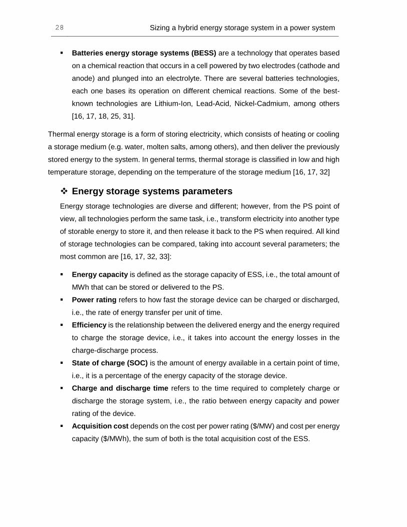
Batteries energy storage systems (BESS) are a technology that operates based
on a chemical reaction that occurs in a cell powered by two electrodes (cathode and
anode) and plunged into an electrolyte. There are several batteries technologies,
each one bases its operation on different chemical reactions. Some of the best-
known technologies are Lithium-Ion, Lead-Acid, Nickel-Cadmium, among others
[16, 17, 18, 25, 31].
Thermal energy storage is a form of storing electricity, which consists of heating or cooling
a storage medium (e.g. water, molten salts, among others), and then deliver the previously
stored energy to the system. In general terms, thermal storage is classified in low and high
temperature storage, depending on the temperature of the storage medium [16, 17, 32]
Energy storage systems parameters
Energy storage technologies are diverse and different; however, from the PS point of
view, all technologies perform the same task, i.e., transform electricity into another type
of storable energy to store it, and then release it back to the PS when required. All kind
of storage technologies can be compared, taking into account several parameters; the
most common are [16, 17, 32, 33]:
Energy capacity is defined as the storage capacity of ESS, i.e., the total amount of
MWh that can be stored or delivered to the PS.
Power rating refers to how fast the storage device can be charged or discharged,
i.e., the rate of energy transfer per unit of time.
Efficiency is the relationship between the delivered energy and the energy required
to charge the storage device, i.e., it takes into account the energy losses in the
charge-discharge process.
State of charge (SOC) is the amount of energy available in a certain point of time,
i.e., it is a percentage of the energy capacity of the storage device.
Charge and discharge time refers to the time required to completely charge or
discharge the storage system, i.e., the ratio between energy capacity and power
rating of the device.
Acquisition cost depends on the cost per power rating ($/MW) and cost per energy
capacity ($/MWh), the sum of both is the total acquisition cost of the ESS.

Chapter 2 29
Hybrid energy storage systems
A Hybrid energy storage system is a combination of two or more electrical storage
technologies with the aim of offer one or more services to a given system, for instance, a
PS. The idea is to take advantage of the strengths of each technology, to thereby overcome
the weaknesses that may have each technology [8].
The concept of hybrid energy storage is relatively new and arises as an extension of the
energy storage with a single technology. The purpose is to integrate several technologies
with supplementary features, aiming to solve the same problems that can be solved just
with a single storage technology, but more efficiently and reducing costs [34, 35].
The introduction of hybrid energy storage systems may become beneficial to power
systems, because of the supplementary characteristics of the different storage
technologies. Some of the advantages are the reduction in the PS operating cost, the
overcoming of a wider range of difficulties than with only a single ESS, and a better
integration of renewable energy than only with a single ESS [8, 34, 2].
In conclusion, the study of HESS is a current subject, which can provide solutions to several
of the PS difficulties. That is why HESS is an important technology for the development of
the modern PS with renewable penetration.
3. Hybrid energy storage system sizing formulation
For this thesis, the main goal is to optimally size a hybrid energy storage system (HESS)
for a power system with renewable energy penetration. This means to properly find the
power rating [MW] and energy capacity [MWh] of both technologies.
The problem framework is embedded into a power system stationary context, thus the
sizing must take into account the effects of the power network. For this reason, the
formulation problem is based on the optimal power flow (OPF) problem.
3.1 Assumptions
The development of this thesis is based on the following assumptions, which are adopted
in the problem formulation:
The proposed optimization problem is a single objective function throughout a
planning horizon. The formulation is done by dividing the horizon in a certain number
of scenarios 𝑁𝑆 (a day); each scenario is divided in certain number of time steps
(𝑁𝑇), all of them with the same length of time (Δ𝑡) [37] equal to 10 minutes.
The optimization problem is a cost function minimization; it consists of three parts
which will be explained in detail in section 3.2.
For this thesis, it will only be considered a steady state problem, i.e., the modeling
of the power system is an electrical network operating in stationary state.
The modeling of the HESS is a stationary state model, because the problem
formulation is a cost function minimization, and the cost per use (section 3.2.3) is
established as a part of the objective function.
Dynamic models of the system and HESS are out of scope in this work, because of
the nature of the objective function, i.e., a cost function minimization, which involves
a steady state modeling of the problem.

Chapter 3 31
Other possible benefits of the HESS are not taking into account in the problem.
3.2 Hybrid energy storage system model
It is necessary to model both long and short-term energy storage systems. Both
technologies are modeled as a generator unit, with the possibility of injecting negative
power, i.e., absorbs power. Moreover, each unit has a variable “energy” associated [38].
An energy storage system (ESS) can be seen like a water tank, with the possibility of being
filled or drained, i.e., a charge or a discharge from the point of view of an energy storage
device. The tank can be filled (or drained) at different rates, meaning that the time required
for completely filling (or draining) depends on the filling/draining rate.
The figure 3-1 illustrates the behavior aforementioned.
Figure 3-1: General modeling of an energy storage system.

32 Sizing a hybrid energy storage system in a power system
The figure shows a tank containing a certain amount of water that can increase up to the
upper limit, i.e., the available capacity. Similarly, it can decrease up to the lower bound, i.e.,
the bottom of the tank. The same behavior occurs in an ESS, whose energy stored must
be less or equal than the maximum storage capacity, and greater or equal than the
minimum storage capacity.
The water available in the tank at any time depends on the amount of water previously
stored, and the operation of the tap of the tank, i.e., the filling (or draining) rate multiplied
by the time of operation. Similarly, in an energy storage device, the energy available at any
time depends on the amount of energy previously stored and the power rate
(charge/discharge) multiplied by the time.
The mathematical model of the HESS has been stated in three different parts, which are:
The behavior of the power, i.e., how the storage device is seen from the power
system perspective.
The behavior of the energy, this means, which are the energy constraints in a
storage device.
The relationship between power and energy, describing how the interaction of these
two variables is in a HESS.
A detailed explanation of the model is explained below.
3.2.1 Behavior of the power in a HESS
An ESS is a device with two possible operating ways: charge and discharge modes. The
model must include both options and it always must be able to relate them. Figure 3–2
explains the charging and discharging behavior in an ESS respectively.

Chapter 3 33
Figure 3-2: Behavior of an energy storage system when is A. charging and B. discharging.
When an ESS is charging, it can be seen as a load from the point of view of the system,
meaning that the system provides the energy necessary to charge the ESS. When an ESS
is discharging, it can be seen as a generator from the point of view of the system. Meaning
that the ESS provides energy to the PS.
Both, long-term and short-term ESS are modeled as explained above, i.e., the power
injected to the power system (or absorbed from it) at any scenario(𝒔), at any time (𝒕) must
be kept between the operation limits of the device. These limits are variables in the HESS
sizing problem and are given by the maximum power rating of each ESS at each bus "𝒊"
where the ESS are installed [37, 14, 39, 40]. This behavior is described in the equation
(3.1).
.
{−𝑃𝐶,𝑖
𝐿𝑇 ≤ 𝑃𝑖𝐿𝑇(𝑠, 𝑡) ≤ 𝑃𝐶,𝑖
𝐿𝑇
−𝑃𝐶,𝑖𝑆𝑇 ≤ 𝑃𝑖
𝑆𝑇(𝑠, 𝑡) ≤ 𝑃𝐶,𝑖𝑆𝑇 (3.1)
Where:

34 Sizing a hybrid energy storage system in a power system
𝑃𝐶,𝑖
𝐿𝑇[𝑀𝑊]: Maximum power rating for Long – Term ESS located at bus"𝑖".
𝑃𝑖𝐿𝑇(𝑠, 𝑡): Power injected (or absorbed) by Long – Term ESS located at bus"𝑖", at
scenario(𝑠), at time(𝑡).
𝑃𝐶,𝑖𝑆𝑇[𝑀𝑊] : Maximum power rating for Short – Term ESS located at bus"𝑖".
𝑃𝑖𝑆𝑇(𝑠, 𝑡): Power injected (or absorbed) by Short – Term ESS located at bus"𝑖", at
scenario(𝑠), at time(𝑡).
The above equations can be rewritten in a simpler way, resulting in the first equation of the HESS model:
{|𝑃𝑖
𝐿𝑇(𝑠, 𝑡)| ≤ 𝑃𝐶.𝑖𝐿𝑇
|𝑃𝑖𝑆𝑇(𝑠, 𝑡)| ≤ 𝑃𝐶.𝑖
𝑆𝑇 (3.2)
It should be noted that the power of a HESS (for any of the two technologies ESS-LT or
ESS-ST) could be less or higher than zero at any scenario(𝒔) at any time(𝒕) because of
the model used to describe the HESS power behavior (a load when it is charging and a
generator when it is discharging).
When the power 𝑃𝑖𝐿𝑇(𝑠, 𝑡) (or 𝑃𝑖
𝑆𝑇(𝑠, 𝑡)) is greater than zero, the ESS – LT (or ESS – ST)
is discharging, and therefore it is injecting power to the system. Instead, when power
𝑃𝑖𝐿𝑇(𝑠, 𝑡) (or 𝑃𝑖
𝑆𝑇(𝑠, 𝑡)) is less than zero, the ESS – LT (or ESS – ST) is charging, and
therefore it is absorbing power from the system.
3.2.2 Behavior of the energy in a HESS
The energy stored by the HESS at any (𝒔) at any (𝒕) should be less than the maximum
energy capacity for each ESS, which is a variable in the sizing HESS problem [37, 14,
39, 40].
{𝐸𝑖
𝐿𝑇(𝑠, 𝑡) ≤ 𝐸𝐶.𝑖𝐿𝑇
𝐸𝑖𝑆𝑇(𝑠, 𝑡) ≤ 𝐸𝐶.𝑖
𝑆𝑇 (3.3)
Where:
𝐸𝐶,𝑖𝐿𝑇[𝑀𝑊ℎ]: Maximum energy capacity for Long – Term ESS located at bus"𝑖".

Chapter 3 35
𝐸𝑖𝐿𝑇(𝑠, 𝑡): Energy stored in the Long – Term ESS located at bus"𝑖" at scenario(𝑠)
at time(𝑡).
𝐸𝐶,𝑖𝑆𝑇[𝑀𝑊ℎ]: Maximum energy capacity for Short – Term ESS located at bus"𝑖".
𝐸𝑖𝑆𝑇(𝑠, 𝑡): Energy stored in the Short – Term ESS located at bus"𝑖" at scenario(𝑠)
at time(𝑡).
3.2.3 Relationship between power and energy in a HESS
The energy stored in the HESS at any scenario (s), at any time (t), depends on the energy
available at the previous point of time (t-1) and the operation of the HESS in the point of
time (t), i.e., the charge or discharge of the HESS. When the HESS is charged, the energy
available at the end of (t) is greater than at the end of (t-1). In contrast, when the HESS is
discharged, the energy available at the end of (t) is less than at the end of (t-1) [37, 14, 39,
40]. The equation (3.4) expresses this behavior.
{𝐸𝑖
𝐿𝑇(𝑠, 𝑡) = 𝐸𝑖𝐿𝑇(𝑠, 𝑡 − 1) − 𝜂𝐿𝑇 ⋅ Δ𝑡 ⋅ 𝑃𝑖
𝐿𝑇(𝑠, 𝑡)
𝐸𝑖𝑆𝑇(𝑠, 𝑡) = 𝐸𝑖
𝑆𝑇(𝑠, 𝑡 − 1) − 𝜂𝑆𝑇 ⋅ Δ𝑡 ⋅ 𝑃𝑖𝑆𝑇(𝑠, 𝑡)
(3.4)
Where:
𝐸𝑖𝐿𝑇(𝑠, 𝑡): Energy stored in the Long – Term ESS located at bus"𝑖" at scenario(𝑠) at
time(𝑡).
𝐸𝑖𝐿𝑇(𝑠, 𝑡 − 1): Energy stored in the Long – Term ESS located at bus"𝑖" at scenario(𝑠)
at time(𝑡 − 1).
𝜂: Round-trip efficiency of the Long – Term ESS
𝑃𝑖𝐿𝑇(𝑠, 𝑡): Power injected (or absorbed) by Long – Term ESS located at bus"𝑖", at
scenario(𝑠), at time(𝑡).
Δ𝑡: Length time duration between two consecutive time steps.
𝐸𝑖𝑆𝑇(𝑠, 𝑡): Energy stored in the Short – Term ESS located at bus"𝑖" at scenario(𝑠) at
time(𝑡).
𝐸𝑖𝑆𝑇(𝑠, 𝑡 − 1): Energy stored in the Short – Term ESS located at bus"𝑖" at scenario(𝑠)
at time(𝑡 − 1).
𝜂: Round-trip efficiency of the Short – Term ESS

36 Sizing a hybrid energy storage system in a power system
𝑃𝑖
𝑆𝑇(𝑠, 𝑡): Power injected (or absorbed) by Short – Term ESS located at bus"𝑖", at
scenario(𝑠), at time(𝑡).
3.3 Objective function
The approach of this dissertation is to propose a single-objective function aiming to size a
HESS in a PS. For this purpose, the formulation is divided into three parts.
The first part minimizes the operation costs in a PS that includes a HESS, the second part
minimizes the investment cost in the HESS, and the third part improves the lifetime of the
HESS as much as possible. Below, these three parts are explained in detail.
3.3.1 Formulation part 1 – Generation costs
Part (1) of the formulation refers to the minimization of the generation operation costs of
the power system, which are based on the conventional OPF, but with the inclusion of
HESS in the system. The equation (3.5) describes this approach.
∑ [∑ (∆𝑡 ∗ ∑ 𝑎𝑖𝑃𝐺𝑖2 (𝑠, 𝑡) + 𝑏𝑖𝑃𝐺𝑖(𝑠, 𝑡) + 𝑐𝑖
𝑁𝐺
𝑖=1
)
𝑁𝑇
𝑡=1
]
𝑁𝑆
𝑠=1
[$] 𝑃𝑎𝑟𝑡 (1) (3.5)
The idea is to divide the time horizon in a finite number of consecutive periods. A dispatch
(OPF) is carried out for each period considering the load and the wind power generation for
the particular period [37, 41, 42, 43]. For example, if the time horizon is a day and it is
divided into time periods of 10 minutes, this would represent 144 periods of simulation. The
formulation is extended if a longer time horizon is required, but the initial approach remains,
i.e., a day of operation is divided in several periods of length ∆𝑡; however, each day is
considered as a scenario of 𝑁𝑆 scenarios.
This formulation discretizes the time horizon in several “blocks” of energy consumption
along the day, but the formulation solves the problem for a specific point of time in the
horizon. That is why it is necessary to multiply the generation costs [$/hr] times the duration
of the interval (∆𝑡) [hr].

Chapter 3 37
3.3.2 Formulation part 2 – Hybrid energy storage system investment cost
Part (2) refers to the investment cost in HESS, the idea is to take full advantage of the
HESS, but at a minimum investment cost.
The investment cost of any ESS is modeled by means of two costs. The first cost is per
energy capacity, i.e., a cost per each [MWh] of the technology; the other cost is for the
power rating, i.e., a cost per each [MW]. This implies that the cost of the HESS technology
depends on four parameters, the power rating and the energy capacity of both ESS-LT and
ESS-ST [44, 45, 46, 47, 48]. The equation (3.6) describes this approach.
∑ 𝐸𝐶,𝑖𝐿𝑇 ⋅ 𝐶𝐸
𝐿𝑇
𝑁𝐵
𝑖=1
+ 𝑃𝐶,𝑖𝐿𝑇 ⋅ 𝐶𝑃
𝐿𝑇 + 𝐸𝐶,𝑖𝑆𝑇 ⋅ 𝐶𝐸
𝑆𝑇 + 𝑃𝐶,𝑖𝑆𝑇 ⋅ 𝐶𝑃
𝑆𝑇𝑃𝑎𝑟𝑡 (2) (3.6)
Where:
𝐸𝐶,𝑖𝐿𝑇[𝑊ℎ]: Maximum energy capacity for Long – Term ESS located at bus"𝑖".
𝐶𝐸𝐿𝑇 [
$
𝑀𝑊ℎ]: Cost of energy capacity for Long – Term ESS.
𝑃𝐶,𝑖𝐿𝑇[𝑊]: Maximum power rating for Long – Term ESS located at bus"𝑖".
𝐶𝑃𝐿𝑇 [
$
𝑀𝑊]: Cost of power for Long – Term ESS.
𝐸𝐶,𝑖𝑆𝑇[𝑊ℎ]: Maximum energy capacity for Short – Term ESS located at bus"𝑖".
𝐶𝐸𝑆𝑇 [
$
𝑀𝑊ℎ]: Cost of energy capacity for Short – Term ESS.
𝑃𝐶,𝑖𝑆𝑇[𝑊]: Maximum power rating for Short – Term ESS located at bus"𝑖".
𝐶𝑃𝑆𝑇 [
$
𝑀𝑊]: Cost of power for Short – Term ESS.
This part addresses the HESS sizing problem, because it includes the power rating and
energy capacity for both technologies (𝐸𝐶,𝑖 𝐿𝑇 ; 𝑃𝐶,𝑖
𝐿𝑇; 𝐸𝐶,𝑖𝑆𝑇; 𝑃𝐶,𝑖
𝑆𝑇) which are the variables of the
sizing problem that have to be found.

38 Sizing a hybrid energy storage system in a power system
It should be taken into account that investment (Part (2)) is limited, this mean that there
exist an available budget to purchase the HESS. This fact implies an extra constraint in the
overall problem, given by:
𝐸𝐶,𝑖𝐿𝑇 ⋅ 𝐶𝐸
𝐿𝑇 + 𝑃𝐶,𝑖𝐿𝑇 ⋅ 𝐶𝑃
𝐿𝑇 + 𝐸𝐶,𝑖𝑆𝑇 ⋅ 𝐶𝐸
𝑆𝑇 + 𝑃𝐶,𝑖𝑆𝑇 ⋅ 𝐶𝑃
𝑆𝑇 ≤ 𝐵𝑢𝑑𝑔𝑒𝑡 (3.7)
The above equation can be seen as a microeconomic problem with two baskets of goods
(ESS-LT and ESS-ST) and a budget constraint. If the entire budget is invested in one good,
e.g. ESS-LT, certain number (quantity) of LT technology can be acquired; therefore, this is
the maximum LT capacity that can be acquired with the available budget (the same occurs
in the case of ESS-ST) [49, 50].
3.3.3 Formulation part 3 – Hybrid energy storage system lifetime improvement
Up to this point of the formulation, it has only been taken into account the operation of the
system and the HESS investment cost in the sizing problem. Although the HESS provides
a benefit to the system, the use of each part of the HESS implies its aging, leading to a
reduction in its lifespan. Each technology has its own lifetime, i.e., a different number of life
cycles. For instance, a Li-ion battery (ESS-LT technology) has about 10000 cycles, while a
supercapacitor (ESS-ST technology) has about 105 - 106 cycles [33].
The idea is to take full advantage of the HESS, while its lifetime is preserved as best as
possible. In this sense, an approach to tackle the HESS lifespan improvement is proposed
as a contribution in this thesis.
First, an approach to find the cost per use of both technologies is stated. The idea is to
formulate an expression that describes the reduction of the life cycles of any technology,
based on its use. Then, with the cost per use defined, an expression to include it in the
HESS sizing problem is formulated.

Chapter 3 39
Cost per use of the hybrid energy storage system
Each energy storage technology has an investment cost and a cycle life1; both of them
are characteristics of each ESS type [51, 52]. When an investor pays a certain amount
of money for an ESS, they are paying for all the available charge/discharge cycles.
Each time that a cycle is completed, one cycle less is available, i.e., there is a
depreciation of the device, which means that certain amount of the inversion already
has been used [53]. With this fact in mind, the cost per use of any technology is
calculated taking into account the following considerations.
o One entire cycle is a complete charge and discharge of the device. The process
has an efficiency known as round-trip efficiency [54], although it is neglected in
this work. Then, one cycle can be considered as two times the energy capacity
of the ESS.
1𝑐𝑦𝑐𝑙𝑒 = 2 ∗ 𝐸𝑐(𝑆𝑇 𝑜𝑟 𝐿𝑇) (3.7)
o The above consideration is valid taking into account that, in the operation of the
system, the energy stored in the HESS is changing along the time. This stored
energy is modeled through the change in the limits, i.e., the charge limit (Pmin)
and the discharge limit (Pmax) change according to the state of charge for both
Long and Short-term ESS. These limits depend on the state of charge of the
HESS, i.e., the energy stored at any point of time and the maximum power rating
of the HESS (𝑃𝐶,𝑖𝐿𝑇; 𝑃𝐶,𝑖
𝑆𝑇). Equations (3.8) and (3.9) describe this approach [55].
𝑃𝑚𝑎𝑥 = min {(𝐸𝑖
𝐿𝑇(𝑠, 𝑡 − 1) − 𝐸𝑚𝑖𝑛)
∆𝑡 ; 𝑃𝐶,𝑖
𝐿𝑇} (3.8)
𝑃𝑚𝑖𝑛 = max {(𝐸𝑖
𝐿𝑇(𝑠, 𝑡 − 1) − 𝐸𝑚𝑎𝑥)
∆𝑡 ; −𝑃𝐶,𝑖
𝐿𝑇} (3.9)
1 The cycle life is the number of complete charge/discharge cycles that the battery is able to support before its capacity falls under 80% of its original capacity.
40 Sizing a hybrid energy storage system in a power system
Where:
𝐸𝑚𝑖𝑛 = 0 is the minimum amount of energy that can be stored by the
HESS.
𝐸𝑚𝑎𝑥 = 𝐸𝐶𝐿𝑇 is the maximum amount of energy that can be stored by the
HESS.
(3.8) and (3.9) has been written in terms of ESS-LT but they are also valid
for the ESS-ST.
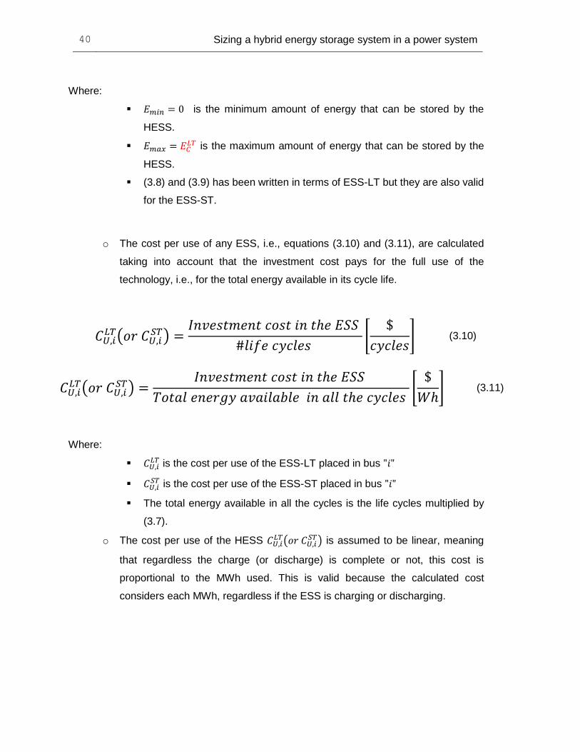
o The cost per use of any ESS, i.e., equations (3.10) and (3.11), are calculated
taking into account that the investment cost pays for the full use of the
technology, i.e., for the total energy available in its cycle life.
𝐶𝑈,𝑖𝐿𝑇(𝑜𝑟 𝐶𝑈,𝑖
𝑆𝑇) =𝐼𝑛𝑣𝑒𝑠𝑡𝑚𝑒𝑛𝑡 𝑐𝑜𝑠𝑡 𝑖𝑛 𝑡ℎ𝑒 𝐸𝑆𝑆
#𝑙𝑖𝑓𝑒 𝑐𝑦𝑐𝑙𝑒𝑠 [
$
𝑐𝑦𝑐𝑙𝑒𝑠] (3.10)
𝐶𝑈,𝑖𝐿𝑇(𝑜𝑟 𝐶𝑈,𝑖
𝑆𝑇) =𝐼𝑛𝑣𝑒𝑠𝑡𝑚𝑒𝑛𝑡 𝑐𝑜𝑠𝑡 𝑖𝑛 𝑡ℎ𝑒 𝐸𝑆𝑆
𝑇𝑜𝑡𝑎𝑙 𝑒𝑛𝑒𝑟𝑔𝑦 𝑎𝑣𝑎𝑖𝑙𝑎𝑏𝑙𝑒 𝑖𝑛 𝑎𝑙𝑙 𝑡ℎ𝑒 𝑐𝑦𝑐𝑙𝑒𝑠 [
$
𝑊ℎ] (3.11)
Where:
𝐶𝑈,𝑖𝐿𝑇 is the cost per use of the ESS-LT placed in bus "𝑖"
𝐶𝑈,𝑖𝑆𝑇 is the cost per use of the ESS-ST placed in bus "𝑖"
The total energy available in all the cycles is the life cycles multiplied by
(3.7).
o The cost per use of the HESS 𝐶𝑈,𝑖𝐿𝑇(𝑜𝑟 𝐶𝑈,𝑖
𝑆𝑇) is assumed to be linear, meaning
that regardless the charge (or discharge) is complete or not, this cost is
proportional to the MWh used. This is valid because the calculated cost
considers each MWh, regardless if the ESS is charging or discharging.

Chapter 3 41
Incorporation of the cost per use of the hybrid energy storage
system in the sizing problem
Once the cost per use has been formulated, it must be incorporated into the formulation of
the sizing problem. Equation (3.12) addresses a way to include it into the problem. The idea
is to add and additional term (Part (3)), that quantifies the use of the HESS and therefore
improves the life of each of its storage components.
∑ ∑ ∑ ∆𝑡 ∗ [𝐶𝑈,𝑖𝐿𝑇 ∗ 𝑃𝑖
𝐿𝑇(𝑠, 𝑡) + 𝐶𝑈,𝑖𝑆𝑇 ∗ 𝑃𝑖
𝑆𝑇(𝑠, 𝑡)]
𝑁𝐵
𝑖=1
𝑁𝑇
𝑡=1
𝑁𝑆
𝑠=1
𝑃𝑎𝑟𝑡 (3) (3.12)
With equation (3.12) the HESS sizing formulation is completed.
3.3.4 Statement of the hybrid energy storage system sizing problem
Finally, after all the parts of the problem formulation were explained, sizing problem is
stated in equation (3.13).
𝑴𝑰𝑵 {(3.5) + (3.6) + (3.12)} (3.13)
Subject to:
I. (𝟐. 𝟕), (𝟐. 𝟖), (𝟐. 𝟗), (𝟐. 𝟏𝟎), (𝟐. 𝟏𝟏), (𝟐. 𝟏𝟐), (𝟐. 𝟏𝟑)
II. (𝟑. 𝟐), (𝟑. 𝟑), (𝟑. 𝟒)
III. (𝟑. 𝟕)

42 Sizing a hybrid energy storage system in a power system
Where:
I. Are the constraints related to the conventional OPF, i.e., with the power system
operation. They include equality and inequality constraints.
II. Are the constraints related to the HESS model, i.e., the behavior of the HESS
along the time.
III. Is the constraint related to the budget available to invest in both technologies,
i.e., the amount of money invested in the HESS should be less or equal than the
available budget.
Table 3-1 summarizes the variables and parameters of the problem.
Table 3-1: Parameters and variables in the HESS sizing problem.
Part of the formulation
Description
SIZING OPTIMIZATION PROBLEM 𝐸𝐶,𝑖
𝐿𝑇 Main Variable (Sizing problem)
𝐶𝐸𝐿𝑇 Input Parameter
𝑃𝐶,𝑖𝐿𝑇 Main Variable (Sizing problem)
𝐶𝑃𝐿𝑇 Input Parameter
𝐸𝐶,𝑖𝑆𝑇 Main Variable (Sizing problem)
𝐶𝐸𝑆𝑇 Input Parameter
𝑃𝐶,𝑖𝑆𝑇 Main Variable (Sizing problem)
𝐶𝑃𝑆𝑇 Input Parameter
𝐵𝑢𝑑𝑔𝑒𝑡 Input parameter HESS
𝑃𝑖𝐿𝑇(𝑠, 𝑡) Variable
𝑃𝑖𝑆𝑇(𝑠, 𝑡) Variable
𝐸𝑖𝐿𝑇(𝑠, 𝑡) Variable
𝐸𝑖𝑆𝑇(𝑠, 𝑡) Variable
GENERATORS 𝑃𝐺𝑖(𝑠, 𝑡) Variable
𝑁𝐺 Parameter 𝑎𝑖 Parameter 𝑏 Parameter 𝑐𝑖 Parameter
𝑃𝐺𝑖𝑚𝑖𝑛 &𝑃𝐺𝑖
𝑚𝑎𝑥 Parameters
𝑉𝐺𝑖𝑚𝑖𝑛 & 𝑉𝐺𝑖
𝑚𝑎𝑥 Parameters LOADS AND PQ BUSES

Chapter 3 43
Load at PQ buses Input data Renewable power
generation Input data
𝑉𝑃𝑄𝑖𝑚𝑖𝑛&𝑉𝑃𝑄𝑖
𝑚𝑎𝑥 Parameter
LINES AND TRANSFORMERS
Lines impedance 𝑍𝐿 Input data Transmission limit 𝑃𝑖𝑗
𝑚𝑎𝑥 Parameter
Power flow through lines 𝑃𝑖𝑗(𝑠, 𝑡)
Variable
Transformer short-circuit impedance 𝑋(𝑠𝑐)𝑖𝑗
Input data
OTHERS Number of buses (𝑁𝐵) Parameter
𝑁𝑇 Parameter 𝛥𝑡 Parameter
3.4 Optimization procedure
For the solution of the HESS sizing problem of equation (3.13), an exhaustive search
method was employed. This method involves the evaluation of the possible solutions in the
search space, through a sampling of the search space, until the global solution of the sizing
problem is found, i.e., the minimum of the objective function [55].
This technique was employed because of the nature of the problem, which aims to find the
best combination of LT and ST technologies, ensuring that the system operating cost plus
the HESS investment is as low as possible, and the investment is always less or equal than
the budget.
The flowchart shown in Figure 3-3 describes the procedure to solve the optimization
problem. It finds the value of the sizing variables for which the objective function
(3.5)+(3.6)+(3.12) is minimized while the constraints are fulfilled

44 Sizing a hybrid energy storage system in a power system
Figure 3-3: HESS sizing.
1. The problem is initialized and all the required data are charged, e.g., load, wind
power, etc.
2. The budget and the investment costs of both technologies are defined; the size of
both technologies are also initialized in 0 MW.

Chapter 3 45
3. It is checked if the budget is greater or equal than the inversion in the HESS. If this
is true the objective function is evaluated. If not, it is skipped to the fifth step.
4. The objective function is evaluated and stored with the aim of being compared to
other values of LT and ST.
5. ST is restarted to zero and LT is increased in 1 MW, with the aim of searching more
possible solutions.
6. ST is increased in 1 MW, with the aim of searching more possible solutions.
7. It is checked if the budget is greater or equal than the investment in the HESS. If
this is true, the objective function is evaluated. If not, this means that the minimum
of the objective function has been found.
8. The search space has been explored, and the minimum of the objective function
has been found.
9. After evaluating the search space, the values of LT and ST that give the minimum
value of the objective function are selected, i.e., the size of the HESS is completed.
10. Finally, the HESS sizing problem has been solved.
HESS Operation
For the development of the HESS sizing problem described in the above flow chart, the
operation of both technologies through the planning horizon is considered, i.e., the behavior
of ESS-LT and ESS-ST across the time.
A planning horizon of one year is assumed, and it is represented in a net average load
curve, described in detail in Chapter 4.
In the case of the ESS-LT, it only charges in time periods when the demand is lower than
the average demand in the net load curve, i.e., in the time periods of low demand.
Conversely, it only discharges in time periods when the demand is higher than the average
demand in the net load curve, i.e., in the time periods of high demand. This strategy is the
same for all cases in the search space, i.e., it is independent of the size of the ESS-LT.
The figure 3-4 shows as an example the previously described behavior of an ESS-LT. This
was made for a 2 MW of ESS-LT.

46 Sizing a hybrid energy storage system in a power system
Figure 3-4: Operation of ESS-LT for 2 MW
In the case of the ESS-ST, there are several charge and discharge cycles throughout the
day. The net load curve is analyzed as time progress, from the first time period to the last
one. The day is divided into several groups of time periods. For each group a charge occurs
in the period of low demand, and a discharge in the period of high demand. In this way, the
operation of ESS-ST is according to the variation of the demand. This strategy is the same
for all cases in the search space, i.e., it is independent of the size of the ESS-ST.
The figure 3-4 shows as an example the behavior of a 2 MW ESS-ST.
Figure 3-5: Operation of ESS-ST for 2 MW

Chapter 3 47
In both cases, the ESS-LT and the ESS-ST, it is possible to implement better operation
strategies that optimize the operation of each technology in each point of the search space.
However, that type of study is out of the scope of this thesis, and it is proposed as a future
work.

4. Results and analysis
Up to this point, the mathematical formulation of the thesis has been stated, which
essentially is a way to address the sizing of a HESS in a power system with renewable
energy penetration.
In this chapter, the sizing formulation previously proposed is implemented in a test system.
Several simulations are carried out in Matlab along with Matpower, which is a toolbox of
Matlab for solving power flow and optimal power flow problems [56].
The optimization problem was solved based on the approach stated in figure 3-3 in chapter
3, which describes the HESS sizing problem, the procedure, and the optimization technique
used.
4.1 Test system
The proposed formulation for sizing a HESS in a power system is tested on the IEEE 14
bus test system. Figure 4-1 illustrates the single line diagram of the system.

Chapter 4 49
Figure 4-1: IEEE 14 bus system single line diagram. Adapted from [57].
Tables 4-1 and 4-2 show the data of this power system.
Table 4-1: Generator parameters for the test system.
Bus location a[$/MW/MWh] b[$/MWh] c[$/h] Capacity [MW] 1 0.04303 20 0 332.4 2 0.25 20 0 140 3 0.01 40 0 100

50 Sizing a hybrid energy storage system in a power system
6 0.01 40 0 100 8 0.01 40 0 100
Table 4-2: Branch parameters for the test system.
Branch From To Resistance
(R) Reactance
(X) Shunt
Susceptance (B) Ratio
1 1 2 0.01938 0.05917 0.0528 1 2 1 5 0.05403 0.22304 0.0492 1 3 2 3 0.04699 0.19797 0.0438 1 4 2 4 0.05811 0.17632 0.034 1 5 2 5 0.05695 0.17388 0.0346 1 6 3 4 0.06701 0.17103 0.0128 1 7 4 5 0.01335 0.04211 0 1 8 4 7 0 0.20912 0 0.978 9 4 9 0 0.55618 0 0.969
10 5 6 0 0.25202 0 0.932 11 6 11 0.09498 0.1989 0 1 12 6 12 0.12291 0.25581 0 1 13 6 13 0.06615 0.13027 0 1 14 7 8 0 0.17615 0 1 15 7 9 0 0.11001 0 1 16 9 10 0.03181 0.0845 0 1 17 9 14 0.12711 0.27038 0 1 18 10 11 0.08205 0.19207 0 1 19 12 13 0.22092 0.19988 0 1 20 13 14 0.17093 0.34802 0 1
For the development of the simulations, a planning horizon of one year it is assumed, i.e.,
365 scenarios according to the formulation in (3.5). Each scenario (one day) is divided in
144 steps, all of them with the same length of time Δ𝑡 = 10 minutes.
A typical load profile is used. It is composed of 144 intervals of 10 minutes each one. The
system has wind power generation, which is considered as a negative load [58]. The figure
4-2 illustrates the net load of the system (load minus wind power). It is assumed that this
curve represents the average net load along the planning horizon, i.e., it is the average net
load in one year.

Chapter 4 51
Figure 4-2: Net load of the system.
4.2 Sizing of the hybrid energy storage system
For the development of the problem, the sizing of a HESS is analyzed. The idea is, given a
certain investment budget, to find the optimal investment in such a way that the HESS
investment cost plus the system operating cost be as low as possible, taking into account
the cost per use of the HESS.
It is used a Li-ion battery as the ESS-LT technology, which has about 10.000 life cycles and
18 years lifetime. A supercapacitor is selected as the ESS-ST technology; it has about 105
life cycles and 20 years lifetime [33].

52 Sizing a hybrid energy storage system in a power system
The table 4-3 shows the acquisition cost for each technology. They are based on the cost
of power and the cost of energy capacity, as well as the discharge time duration [33, 4.5].
Table 4-3: Investment data of the HESS.
PARAMETER ESS-LT ESS-ST Cost of power capacity [$/kW] 150 300 Cost of energy capacity [$/kWh] 300 1000 Discharge duration [h] 4 1/4 Investment cost[$/MW] 1’350.000 550.000
The investment cost is estimated based on equation (4.1), i.e., the cost of power and cost
of energy capacity are taking into account, as well as the discharge time duration. According
to the power rating and the discharge duration of the device, energy capacity is calculated
(power multiplied by time). Equation (4.1) shows the investment cost of the ESS-LT (which
is the same for the ESS-ST).
𝐼𝑛𝑣𝑒𝑠𝑡𝑚𝑒𝑛𝑡 𝑐𝑜𝑠𝑡 (𝐸𝑆𝑆 − 𝐿𝑇) = 𝐸𝐶𝐿𝑇 ⋅ 𝐶𝐸
𝐿𝑇 + 𝑃𝐶𝐿𝑇 ⋅ 𝐶𝑃
𝐿𝑇 (4.1)
Where:
𝐸𝐶𝐿𝑇[𝑊ℎ]: Maximum energy capacity for Long – Term ESS
𝐶𝐸𝐿𝑇 [
$
𝑀𝑊ℎ]: Cost of energy capacity for Long – Term ESS.
𝑃𝐶𝐿𝑇[𝑊]: Maximum power rating for Long – Term.
𝐶𝑃𝐿𝑇 [
$
𝑀𝑊]: Cost of power for Long – Term ESS.
Three different cases are analyzed. The first case is the system operating without storage
systems, the second case is the system operating only with ESS- LT. Finally, the third case
is the system with the HESS.
4.2.1 Case 1 – System without energy storage systems
For this first case, the operation cost is analyzed when no storage device is operating, i.e.,
it is a baseline case for subsequent analyses. The investment cost is equal to zero because
there is not any ESS in the power system.

Chapter 4 53
It is assumed that the used load profile represents the average net load in one year, as it
was previously mentioned. Based on this fact, one year of the PS operation is analyzed,
and an operation cost of $20.198.324,00 was obtained using the procedure described in
section 3.3.
4.2.2 Case 2 – System with long-term energy storage system
For this second case, the behavior of the power system is analyzed when only an ESS-LT
is operating. For this case, the available investment budget is a variable, i.e., it takes
different values, and then it is estimated how much ESS-LT capacity can be acquired. The
operation cost in one year is estimated afterwards.
The table 4-4 shows the results. The first column is the available investment budget, the
second column is the acquired ESS-LT capacity, the third column is the investment cost,
which is the investment budget divided by the estimated lifetime of the technology in years,
the fourth column is the operation cost, and the fifth column is the objective function value
calculated after applying the model described in Chapter 3.
Table 4-4: Results when only ESS-LT is acquired.
BUDGET [$] LT [MW] INVESTMENT [$] OPER. COST [$] OBJ F N/A 0 0 20.198.324,00 20.198.324,00
4.000.000,00 2 150.000,00 20.035.454,44 20.185.454,44 5.000.000,00 3 225.000,00 19.947.605,62 20.172.605,62 6.000.000,00 4 300.000,00 19.874.012,75 20.174.012,75 7.000.000,00 5 375.000,00 19.787.580,43 20.162.580,43 8.000.000,00 5 375.000,00 19.787.580,43 20.163.000,00 9.000.000,00 6 450.000,00 19.703.682,68 20.153.682,68
10.000.000,00 7 525.000,00 19.628.572,06 20.154.000,00 11.000.000,00 8 600.000,00 19.547.221,56 20.147.221,56 12.000.000,00 8 600.000,00 19.547.221,56 20.147.221,56
It can be seen how as the available budget increases, the acquired ESS-LT capacity
increases too, and the operation cost of the PS decreases. This means that the introduction
of the ESS-LT reduces the operation cost. The figure 4-3 illustrates this behavior.

54 Sizing a hybrid energy storage system in a power system
Figure 4-3: Reduction of the operation cost of the PS as a function of the ESS-LT capacity.
4.2.3 Case 3 – System with the hybrid energy storage system
For this third case, the behavior of the power system is analyzed when a HESS is operating.
The idea is to find the best investment decision for the acquisition of the technologies ESS-
LT and ESS-ST taking into account the available budget. Again, the investment budget
gradually increases, starting at $2.000.000,00 until $12.000.000,00 in steps of
$500.000,00.
The table 4-5 shows the results. The first column is the available investment budget, the
second and third columns are the investment percentages in ESS-LT and ES-ST
respectively, the fourth and fifth columns are the ESS-LT and ESS-ST acquired capacity,
the sixth column is the investment cost, the seventh column is the operation cost, and the
eighth column is the objective function value.

Chapter 4 55
Table 4-5: Results when only ESS-LT is acquired.
BUDGET. [$] %LT %ST LT [MW] ST [MW] INVERSIÓN[$] OP COST. [$] OBJ F 2.000.000,00 71 29 1 1 102.500,00 20.078.910,84 20.181.410,84 2.500.000,00 55 45 1 2 130.000,00 20.042.332,02 20.172.332,02 3.000.000,00 55 45 1 2 130.000,00 20.042.332,02 20.172.332,02 3.500.000,00 83 17 2 1 177.500,00 19.998.666,58 20.169.725,67 4.000.000,00 71 29 2 2 205.000,00 19.962.119,32 20.167.119,32 4.500.000,00 71 29 2 2 205.000,00 19.962.119,32 20.167.119,32 5.000.000,00 88 12 3 1 252.500,00 19.910.854,35 20.163.354,35 5.500.000,00 79 21 3 2 280.000,00 19.874.343,83 20.154.343,83 6.000.000,00 79 21 3 2 280.000,00 19.874.343,83 20.154.343,83 6.500.000,00 79 21 3 2 280.000,00 19.874.343,83 20.154.343,83 7.000.000,00 79 21 3 2 280.000,00 19.874.343,83 20.154.343,83 7.500.000,00 92 8 5 1 402.500,00 19.750.901,90 20.153.401,90 8.000.000,00 86 14 5 2 430.000,00 19.714.464,08 20.144.535,05 8.500.000,00 86 14 5 2 430.000,00 19.714.464,08 20.144.464,08 9.000.000,00 94 6 6 1 477.500,00 19.667.035,05 20.144.464,08 9.500.000,00 88 12 6 2 505.500,00 19.630.628,31 20.135.628,31
10.000.000,00 88 12 6 2 505.000,00 19.630.628,31 20.135.628,31 10.500.000,00 88 12 6 2 505.000,00 19.630.628,31 20.135.628,31 11.000.000,00 90 10 7 2 580.000,00 19.555.601,42 20.135.601,42 11.500.000,00 90 10 7 2 580.000,00 19.555.601,42 20.135.601,42 12.000.000,00 91 9 8 2 655.000,00 19.474.312,80 20.129.312,80
The figure 4-4 shows the investment percentage for ESS-LT and ESS-ST, according to the
available budget, i.e., the sizing of the HESS.

Figure 4-4: Sizing of the HESS.

It can be seen that the operational cost of the power system decreases when a HESS is
operating. With the increasing of the available budget, the operation cost decreases, as
well as the objective function value.
Moreover, given an investment budget, the operational cost of the power system with HESS
is less than the one of the system having only an ESS-LT. Similarly, the objective function
value has the same behavior, i.e., it is lower with HESS than only with ESS-LT.
In general, the introduction of the HESS in a power system brings benefits to the system,
since the operational cost is reduced, this can be seen in the reduction of the operation cost
as well as in the objective function.
With a greater available investment budget, it is possible to acquire a higher HESS capacity,
i.e., an increase in the budget leads to a higher reduction in the PS operational cost.
The Figure 4-5 shows the behavior of the HESS sizing, i.e., the evolution of the investment
in ESS-LT and ESS-ST as the budget increases.
Figure 4-5: Behavior of the HESS sizing.

58 Sizing a hybrid energy storage system in a power system
It can be seen that the behavior of the ESS-LT investment is opposite to the ESS-ST
investment, since when the budget is increasing, it can be appreciated an increase in the
ESS-LT acquisition percentage, while the ESS-ST acquisition percentage decreases. In
general, the ESS-LT brings more energy to the system than the ESS-LT. That is why always
the investment is bigger for the ESS-LT than for the ESS-ST.
Reduction in the acquisition cost of the energy storage short-
term technology.
In this case, the gradual decrease of the acquisition cost of the ESS-ST is simulated, while
the acquisition cost of the ESS-LT remains equal. The idea is to verify how sensitive is the
HESS sizing when the ESS-ST costs are dropping, as it is expected to be in the future.
The figures 4-6 and 4-7 show the variation of the investment percentage for both
technologies when the acquisition cost of the ESS-ST is decreasing, i.e., the variation of
the HESS sizing.
Figure 4-6: Behavior of the HESS sizing for $4.000.000,00 budget, when ESS-LT acquisition cost remains equal, and ESS-ST acquisition cost gradually decrease.
Chapter 4 59
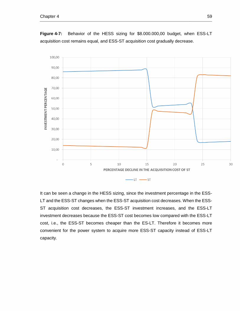
Figure 4-7: Behavior of the HESS sizing for $8.000.000,00 budget, when ESS-LT
acquisition cost remains equal, and ESS-ST acquisition cost gradually decrease.
It can be seen a change in the HESS sizing, since the investment percentage in the ESS-
LT and the ESS-ST changes when the ESS-ST acquisition cost decreases. When the ESS-
ST acquisition cost decreases, the ESS-ST investment increases, and the ESS-LT
investment decreases because the ESS-ST cost becomes low compared with the ESS-LT
cost, i.e., the ESS-ST becomes cheaper than the ES-LT. Therefore it becomes more
convenient for the power system to acquire more ESS-ST capacity instead of ESS-LT
capacity.

5. Conclusions and future work
The present research work develops a proposal for sizing a hybrid energy storage system
in a power system. The aim is to minimize the operational cost of the system plus the
investment cost in HESS, considering the cost of using the different storage technologies.
5.1 Conclusions
The operational cost of the power system decreases when a long-term energy storage
system is implemented, compared to the operational cost when no storage is available.
Moreover, if a hybrid energy storage system is implemented, the operational cost is less
than the case when there is only a long-term energy storage system.
For a given available budget, the higher proportion of the investment is always dedicated
to the ESS-LT because this technology provides more energy to the power system.
Conversely, the lower proportion of the investment is dedicated to the ESS-ST, because
although this technology provides less energy compared with the ESS-LT, its cost per use
is less than the ESS-LT.
In the analyzed test case, for an investment budget of $4.000.000,00, the investment
percentage on ESS-ST rises from 30% to 58% when the investment cost of ESS-ST is
reduced in 15% of its original value. Conversely, the investment percentage on ESS-LT
decreases in that scenario. The very same behavior occurs for an investment budget of
$8.000.000,00. In this case, when the investment cost of ESS-ST decreases in a 15%, the
investment percentage rises from 14% to 82% and the ESS-ST investment percentage
decreases. This happens because when the purchase costs of ESS-ST are decreased
enough for the sum of the investment costs in the HESS plus the operation costs to become
less when one invests more in ESS-ST than in ESS-LT.
A methodology for designing a Hybrid Energy Storage System was developed, taking into
account technical and economic aspects in the formulation.

62 Sizing a hybrid energy storage system in a power system
The concept of "available budget" was included in the proposed sizing problem.
It was possible to include the concept of "cost per use" in the proposed methodology of
sizing a HESS.
It was demonstrated that the steady state modeling of the problem was enough to solve the
research problem; however, it is proposed the use of dynamic state models in future works.
5.2 Recommendations
The development of the topic of the hybrid energy storage system in power systems is still
incipient, and the available literature is reduced. Therefore, there are several potential
topics to be developed in the future.
For instance, a researcher may include other objectives in the problem formulation in
addition to cost minimization, with the aim of analyze the HESS sizing when several
objectives are taking into account.
Another area is to include in the sizing problem other conditions different to the steady-state
condition of the power system; for instance, to quantify the benefits in transient stability,
frequency oscillations, among others.
Finally, the optimal operation of each technology of the HESS can be studied, i.e., to
investigate the best way of operating the HESS in the planning horizon for each point of the
search space, aiming to fulfill one or several objectives functions in the HESS sizing.

Bibliography 63
Bibliography
[1] Gopstein, A.M., "Energy Storage & the Grid - From Characteristics to Impact [Point of View]," Proceedings of the IEEE , vol.100, no.2, pp.311,316, Feb. 2012
[2] Kyriakopoulos, G. L., & Arabatzis, G. (2016). Electrical energy storage systems in
electricity generation: energy policies, innovative technologies, and regulatory regimes.
Renewable and Sustainable Energy Reviews, 56, 1044-1067.
[3] Hadjipaschalis, I., Poullikkas, A., & Efthimiou, V. (2009). Overview of current and
future energy storage technologies for electric power applications. Renewable and
sustainable energy reviews, 13(6), 1513-1522.
[4] Hammons, T.; Styczynski, Z., "Europe: Impact of Dispersed Generation on Power
System Structure and Secure Power System Operation," Power Engineering Society
General Meeting, 2007. IEEE , vol., no., pp.1,5, 24-28 June 2007
[5] Bhatnagar, N.; Venkatesh, B., "Energy storage and power systems," Electrical &
Computer Engineering (CCECE), 2012 25th IEEE Canadian Conference on , vol., no.,
pp.1,4, April 29 2012-May 2 2012
[6] Ribeiro, P.F.; Johnson, B.K.; Crow, M.L.; Arsoy, A.; Liu, Y., "Energy storage systems
for advanced power applications," Proceedings of the IEEE , vol.89, no.12, pp.1744,1756,
Dec 2001
[7] Miranda, I.; Silva, N.; Leite, H., "Technical and economic assessment for optimal
sizing of distributed storage," Innovative Smart Grid Technologies (ISGT Europe), 2012 3rd
IEEE PES International Conference and Exhibition on , vol., no., pp.1,6, 14-17 Oct. 2012
[8] Delgado-Gomes, V.; Borza, P.N., "A biological approach for energy management in
smart grids and hybrid energy storage systems," Optimization of Electrical and Electronic
Equipment (OPTIM), 2014 International Conference on , vol., no., pp.1082,1086, 22-24
May 2014

64 Sizing a hybrid energy storage system in a power system
[9] J. A. Momoh, Electric Power System Applications of Optimization, Washington D.C.:
Marcel Dekker, Inc., 2001.
[10] Cain, M. B., O’neill, R. P., & Castillo, A. (2012). History of optimal power flow and
formulations. Federal Energy Regulatory Commission, 1-36.
[11] Zhu, J., "Optimal Power Flow," in Optimization of Power System Operation, 1, Wiley-
IEEE Press, 2009, pp.297-364
[12] Kahourzade, S., Mahmoudi, A., & Mokhlis, H. B. (2015). A comparative study of
multi-objective optimal power flow based on particle swarm, evolutionary programming, and
genetic algorithm. Electrical Engineering, 97(1), 1-12.
[13] Leeton, U.; Uthitsunthorn, D.; Kwannetr, U.; Sinsuphun, N.; Kulworawanichpong, T.,
"Power loss minimization using optimal power flow based on particle swarm optimization,"
in Electrical Engineering/Electronics Computer Telecommunications and Information
Technology (ECTI-CON), 2010 International Conference on , vol., no., pp.440-444, 19-21
May 2010.
[14] Xiao Zhang; Feng Gao; Xinjie Lv; Hairong Lv; Qiming Tian; Junhua Ma; Wenjun Yin;
Jin Dong, "Line loss reduction with distributed energy storage systems," in Innovative Smart
Grid Technologies - Asia (ISGT Asia), 2012 IEEE , vol., no., pp.1-4, 21-24 May 2012.
[15] Varadarajan, M., & Swarup, K. S. (2008). Solving multi-objective optimal power flow
using differential evolution. Generation, Transmission & Distribution, IET,2(5), 720-730.
[16] Chen, H., Cong, T. N., Yang, W., Tan, C., Li, Y., & Ding, Y. (2009). Progress in
electrical energy storage system: A critical review. Progress in Natural Science, 19(3), 291-
312.
[17] Kousksou, T., Bruel, P., Jamil, A., El Rhafiki, T., & Zeraouli, Y. (2014). Energy
storage: Applications and challenges. Solar Energy Materials and Solar Cells, 120, 59-80.
[18] Electrical Energy Storage. IEC White Paper; December 2011
[19] Bolund, B., Bernhoff, H., & Leijon, M. (2007). Flywheel energy and power storage
systems. Renewable and Sustainable Energy Reviews, 11(2), 235-258.

Bibliography 65
[20] Liu, H., & Jiang, J. (2007). Flywheel energy storage—An upswing technology for
energy sustainability. Energy and buildings, 39(5), 599-604.
[21] Daneshi, A., Sadrmomtazi, N., Daneshi, H., & Khederzadeh, M. (2010, November).
Wind power integrated with compressed air energy storage. In Power and Energy (PECon),
2010 IEEE International Conference on (pp. 634-639). IEEE.
[22] Lund, H., & Salgi, G. (2009). The role of compressed air energy storage (CAES) in
future sustainable energy systems. Energy conversion and management, 50(5), 1172-
1179.
[23] Deane, J. P., Gallachóir, B. Ó., & McKeogh, E. J. (2010). Techno-economic review
of existing and new pumped hydro energy storage plant. Renewable and Sustainable
Energy Reviews, 14(4), 1293-1302.
[24] Abbey, C., & Joos, G. (2007). Supercapacitor energy storage for wind energy
applications. IEEE Transactions on Industry Applications, 43(3), 769-776.
[25] Winter, M., & Brodd, R. J. (2004). What are batteries, fuel cells, and
supercapacitors?. Chemical reviews, 104(10), 4245-4270.
[26] Sharma, P., & Bhatti, T. S. (2010). A review on electrochemical double-layer
capacitors. Energy Conversion and Management, 51(12), 2901-2912.
[27] M. H. Ali, B. Wu and R. A. Dougal, "An Overview of SMES Applications in Power
and Energy Systems," in IEEE Transactions on Sustainable Energy, vol. 1, no. 1, pp. 38-
47, April 2010.
[28] K. E. Nielsen and M. Molinas, "Superconducting Magnetic Energy Storage (SMES)
in power systems with renewable energy sources," 2010 IEEE International Symposium on
Industrial Electronics, Bari, 2010, pp. 2487-2492.
[29] Melaina, M., & Eichman, J. (2015). Hydrogen Energy Storage: Grid and
Transportation Services. Technical Report NREL/TP-5400-62518, http://www. nrel.
gov/docs/fy15osti/62518. pdf.

66 Sizing a hybrid energy storage system in a power system
[30] Energy Storage Association, "Energy Storage Association," [Online]. Available:
http://energystorage.org/energy-storage/technologies/hydrogen-energy-storage.
[31] Bussar, R., Lippert, M., Bonduelle, G., Linke, R., Crugnola, G., Cilia, J., ... & Marckx,
E. (2013). Battery energy storage for smart grid applications. EuroBat, May.
[32] I. Renewable and E. Agency, “IRENA-IEA-ETSAP Technology Brief 4: Thermal
Storage,” no. January, 2013.
[33] Fuchs, G., Lunz, B., Leuthold, M., & Sauer, D. U. (2012). Technology Overview on
Electricity Storage: Overview on the potential and on the deployment perspectives of
electricity storage technologies. On behalf of Smart Energy for Europe Platform GmbH
(SEFEP). ISEA RWTH Aachen.
[34] Bocklisch, T. (2015). Hybrid energy storage systems for renewable energy
applications. Energy Procedia, 73, 103-111.
[35] Luo, X., Wang, J., Dooner, M., & Clarke, J. (2015). Overview of current development
in electrical energy storage technologies and the application potential in power system
operation. Applied Energy, 137, 511-536.
[36] Wankhade, C. M., & Vaidya, A. P. (2014). Optimal Power Flow Using Genetic
Algorithm: Parametric Studies for Selection of Control and State Variables. British Journal
of Applied Science & Technology, 4(2), 279-301.
[37] Baker, Kyri A., "Coordination of Resources Across Areas for the Integration of
Renewable Generation: Operation, Sizing, and Siting of Storage Devices" (2014).
Dissertations. Paper 465. http://repository.cmu.edu/dissertations/465
[38] Chandy, K. M., Low, S. H., Topcu, U., & Xu, H. (2010, December). A simple optimal
power flow model with energy storage. In Decision and Control (CDC), 2010 49th IEEE
Conference on (pp. 1051-1057). IEEE.

Bibliography 67
[39] Sjodin, E., Gayme, D. F., & Topcu, U. (2012, June). Risk-mitigated optimal power
flow for wind powered grids. In American Control Conference (ACC), 2012(pp. 4431-4437).
IEEE.
[40] Maffei, A., Meola, D., Marafioti, G., Palmieri, G., Iannelli, L., Mathisen, G., & Glielmo,
L. (2014). Optimal Power Flow model with energy storage, an extension towards large
integration of renewable energy sources.⋆. Proc. 19th World Congr. Int. Fed. Autom.
Control, 9456-9461
[41] Haoran Zhao; Qiuwei Wu; Shaojun Huang; Qinglai Guo; Hongbin Sun; Yusheng
Xue, "Optimal siting and sizing of Energy Storage System for power systems with large-
scale wind power integration," inPowerTech, 2015 IEEE Eindhoven , vol., no., pp.1-6, June
29 2015-July 2 2015
[42] Wogrin, S.; Gayme, D.F., "Optimizing Storage Siting, Sizing, and Technology
Portfolios in Transmission-Constrained Networks," in Power Systems, IEEE Transactions
on , vol.30, no.6, pp.3304-3313, Nov. 2015
[43] Pandzic, H.; Yishen Wang; Ting Qiu; Dvorkin, Y.; Kirschen, D.S., "Near-Optimal
Method for Siting and Sizing of Distributed Storage in a Transmission Network," in Power
Systems, IEEE Transactions on , vol.30, no.5, pp.2288-2300, Sept. 2015
[44] Chakraborty, S., Senjyu, T., Toyama, H., Saber, A. Y., & Funabashi, T. (2009).
Determination methodology for optimising the energy storage size for power system. IET
generation, transmission & distribution, 3(11), 987.
[45] Etinski, M.; Schulke, A., "Optimal hybrid energy storage for wind energy integration,"
in Industrial Technology (ICIT), 2013 IEEE International Conference on , vol., no., pp.1769-
1774, 25-28 Feb. 2013
[46] Chen, S.X.; Gooi, H.B., "Sizing of energy storage system for microgrids,"
in Probabilistic Methods Applied to Power Systems (PMAPS), 2010 IEEE 11th International
Conference on , vol., no., pp.6-11, 14-17 June 2010

68 Sizing a hybrid energy storage system in a power system
[47] Dutta, S.; Sharma, R., "Optimal storage sizing for integrating wind and load forecast
uncertainties," in Innovative Smart Grid Technologies (ISGT), 2012 IEEE PES , vol., no.,
pp.1-7, 16-20 Jan. 2012
[48] Nguyen, T.A.; Crow, M.L.; Elmore, A.C., "Optimal Sizing of a Vanadium Redox
Battery System for Microgrid Systems," in Sustainable Energy, IEEE Transactions on ,
vol.6, no.3, pp.729-737, July 2015
[49] Gans, J., King, S., & Mankiw, N. G. (2011). Principles of microeconomics. Cengage
Learning
[50] W. Nicholson, Teoría microeconómica. Principios básicos y ampliaciones, México,
D.F.: Cengage Learning, 2008.
[51] Inage, S. I. (2009). Prospects for large-scale energy storage in decarbonized power
grids. International Energy Agency, IEA.
[52] Leland, B., & Anthony, T. (2001). Ingeniería Económica, 4ta. Edición, Mac Graw
Hill, Colombia.
[53] Ibrahim, H., & Ilinca, A. (2013). Techno-economic analysis of different energy
storage technologies. INTECH Open Access Publisher.
[54] Martinez, M., Molina, M. G., & Mercado, P. E. (2015). Optimal Storage Technology
Selection and Sizing for Providing Reserve to Power Systems with High Penetration of
Wind Generation. Latin America Transactions, IEEE (Revista IEEE America Latina),13(9),
2983-2990
[55] Burke, E. K., & Kendall, G. (2005). Search methodologies (pp. 1-17). Springer
Science+ Business Media, Incorporated.
[56] R. D. Zimmerman, C. E. Murillo-Sánchez, and R. J. Thomas, Matpower: Steady-
State Operations, Planning and Analysis Tools for Power Systems Research and
Education," Power Systems, IEEE Transactions on, vol. 26, no. 1, pp. 12{19, Feb. 2011.

Bibliography 69
[57] University of Washington, «UNIVERSITY OF WASHINGTON ELECTRICAL
ENGINEERING,1999. [Online]. Available: https://www.ee.washington.edu/research/pstca/.
[58] Data of the wind power generation, available on: http://wind.nrel.gov/Web_nrel/