Size-dependent behaviour of functionally graded sandwich...
43
Citation: Thai, Huu-Tai, Vo, Thuc, Nguyen, Trung-Kien and Lee, Jaehong (2015) Size- dependent behaviour of functionally graded sandwich microbeams based on the modified couple stress theory. Composite Structures, 123. pp. 337-349. ISSN 0263-8223 Published by: Elsevier URL: http://dx.doi.org/10.1016/j.compstruct.2014.11.065 <http://dx.doi.org/10.1016/j.compstruct.2014.11.065> This version was downloaded from Northumbria Research Link: http://nrl.northumbria.ac.uk/18467/ Northumbria University has developed Northumbria Research Link (NRL) to enable users to access the University’s research output. Copyright © and moral rights for items on NRL are retained by the individual author(s) and/or other copyright owners. Single copies of full items can be reproduced, displayed or performed, and given to third parties in any format or medium for personal research or study, educational, or not-for-profit purposes without prior permission or charge, provided the authors, title and full bibliographic details are given, as well as a hyperlink and/or URL to the original metadata page. The content must not be changed in any way. Full items must not be sold commercially in any format or medium without formal permission of the copyright holder. The full policy is available online: http://nrl.northumbria.ac.uk/policies.html This document may differ from the final, published version of the research and has been made available online in accordance with publisher policies. To read and/or cite from the published version of the research, please visit the publisher’s website (a subscription may be required.)
Transcript of Size-dependent behaviour of functionally graded sandwich...

Citation: Thai, Huu-Tai, Vo, Thuc, Nguyen, Trung-Kien and Lee, Jaehong (2015) Size-dependent behaviour of functionally graded sandwich microbeams based on the modified couple stress theory. Composite Structures, 123. pp. 337-349. ISSN 0263-8223
Published by: Elsevier
URL: http://dx.doi.org/10.1016/j.compstruct.2014.11.065 <http://dx.doi.org/10.1016/j.compstruct.2014.11.065>
This version was downloaded from Northumbria Research Link: http://nrl.northumbria.ac.uk/18467/
Northumbria University has developed Northumbria Research Link (NRL) to enable users to access the University’s research output. Copyright © and moral rights for items on NRL are retained by the individual author(s) and/or other copyright owners. Single copies of full items can be reproduced, displayed or performed, and given to third parties in any format or medium for personal research or study, educational, or not-for-profit purposes without prior permission or charge, provided the authors, title and full bibliographic details are given, as well as a hyperlink and/or URL to the original metadata page. The content must not be changed in any way. Full items must not be sold commercially in any format or medium without formal permission of the copyright holder. The full policy is available online: http://nrl.northumbria.ac.uk/policies.html
This document may differ from the final, published version of the research and has been made available online in accordance with publisher policies. To read and/or cite from the published version of the research, please visit the publisher’s website (a subscription may be required.)

Accepted Manuscript
Size-dependent behaviour of functionally graded sandwich microbeams based
on the modified couple stress theory
Huu-Tai Thai, Thuc P. Vo, Trung-Kien Nguyen, Jaehong Lee
PII: S0263-8223(14)00646-1
DOI: http://dx.doi.org/10.1016/j.compstruct.2014.11.065
Reference: COST 6050
To appear in: Composite Structures
Please cite this article as: Thai, H-T., Vo, T.P., Nguyen, T-K., Lee, J., Size-dependent behaviour of functionally
graded sandwich microbeams based on the modified couple stress theory, Composite Structures (2014), doi: http://
dx.doi.org/10.1016/j.compstruct.2014.11.065
This is a PDF file of an unedited manuscript that has been accepted for publication. As a service to our customers
we are providing this early version of the manuscript. The manuscript will undergo copyediting, typesetting, and
review of the resulting proof before it is published in its final form. Please note that during the production process
errors may be discovered which could affect the content, and all legal disclaimers that apply to the journal pertain.
1
Size-dependent behaviour of functionally graded sandwich
microbeams based on the modified couple stress theory
Huu-Tai Thai a,∗, Thuc P. Vo b, Trung-Kien Nguyen c, Jaehong Lee d
a Centre for Infrastructure Engineering and Safety, School of Civil and Environmental Engineering, The University of New South Wales, Sydney, NSW 2052, Australia
b Faculty of Engineering and Environment, Northumbria University, Newcastle upon Tyne
NE1 8ST, UK c Faculty of Civil Engineering and Applied Mechanics, University of Technical Education Ho
Chi Minh City, 1 Vo Van Ngan Street, Thu Duc District, Ho Chi Minh City, Vietnam d Department of Architectural Engineering, Sejong University, 98 Kunja Dong, Kwangjin Ku,
Seoul 143-747, Korea
Abstract
Static bending, buckling and free vibration behaviours of size-dependent functionally
graded (FG) sandwich microbeams are examined in this paper based on the modified
couple stress theory and Timoshenko beam theory. To avoid the use of a shear
correction factor, equilibrium equations were used to compute the transverse shear force
and shear stress. Two types of sandwich beams were considered: (1) homogeneous core
and FG skins and (2) FG core and homogeneous skins. Numerical results were
presented to illustrate the small scale effects on the behaviours of FG sandwich beams.
The results reveals that the inclusion of the size effects results in an increase in the beam
stiffness, and consequently, leads to a reduction of deflections and stresses and an
increase in natural frequencies and critical buckling loads. Such effects are more
pronounced when the beam depth was small, but they become negligible with the
increase of the beam depth.
Keywords: Functionally graded sandwich beam; small scale effect; modified couple
∗ Corresponding author. Tel.: + 61 2 9385 5029. E-mail address: [email protected] (H.T. Thai)

2
stress theory; Timoshenko beam
1. Introduction
Sandwich structures have been widely used in automotive, marine and aerospace
industries due to their high strength-to-weight ratio. Conventional sandwich structures
composed of a soft core bonded to two thin and stiff skins exhibit the delamination
problems at the bond interfaces due to the sudden change in material properties between
layers. To overcome this problem, functionally graded (FG) sandwich structures were
proposed in which the core or two skins can be made from functionally graded materials
(FGMs). The FGM is a kind of advanced composites in which its material properties
vary smoothly from one surface to another, and thus eliminating the stress concentration
found in laminated composites.
The application of FGMs in micro- and nano-scale devices and systems such as thin
films [1], atomic force microscopes [2], micro- and nano-electro-mechanical systems
(MEMS and NEMS) [3] has been increasingly in recent years. In such applications, size
effects were experimentally observed [4-6]. The size effect can be captured using size-
dependent continuum theories. In view of the difficulties in determining the material
length scale parameters, Yang et al. [7] proposed the modified couple stress theory in
which only one length scale parameter is required. There have been a number of size-
dependent models developed for FG beams based on the modified couple stress theory
[8-18]. These size-dependent models adopted various beam theories such as Euler-
Bernoulli beam theory (EBT) [8-11], Timoshenko beam theory (TBT) [9-10, 12-14],
and higher-order shear deformation beam theory (HBT) [10, 15-18]. It is worth noting
that the EBT is the simplest one but it neglects the shear deformation effect which is
significant in advanced composites like FGMs. The TBT accounts for the shear

3
deformation effect but it requires a shear correction factor which is hard to determine
consistently. Although the HBTs do account for the shear deformation effect without
requiring the shear correction factor, their equations of motion are more complicated
than those of the TBT.
Although the size-dependent beam models based on the modified couple stress theory
have been developed and well discussed in the above-mentioned studies for FG beams,
no literature has been reported for the size-dependent behaviours of FG sandwich beams.
This paper therefore aims to investigate the size-dependent behaviours of FG sandwich
beams based on the modified couple stress theory and the TBT. To avoid the use of a
shear correction factor in the Timoshenko beam theory, equilibrium equations were used
to compute the transverse shear force and shear stress. FG sandwich beams with either
two skins or a core made of FGMs were considered in this study. Numerical examples
for simply supported beams were presented to investigate the influences of small scale
on deflections, stresses, critical buckling loads and natural frequencies of FG sandwich
beams.
2. Theoretical formulation
In this section, the formulations of a size-dependent FG sandwich beam model were
briefly presented. The effects of the small scale and shear deformation were respectively
accounted for using the modified couple stress theory and Timoshenko beam theory.
Analytical solutions of simply supported beams were also presented using Navier-type
solutions.
2.1. Governing equations of motion
In the modified couple stress theory, the strain energy is expressed in terms of both
strain tensor and curvature tensor as [7]:

4
( )1
2 ij ij ij ijVU m dVσ ε χ= +∫ (1)
where ijσ and ijε are the components of the stress tensor and strain tensor; ijm and
ijχ denote the components of the deviatoric part of the symmetric couple stress tensor
and symmetric curvature tensor defined by:
22 , , 1, 2,3ij ijm G i jχ= =� (2)
1
, , 1,2,32
jiij
j i
i jx x
θθχ⎛ ⎞∂∂= + =⎜ ⎟⎜ ⎟∂ ∂⎝ ⎠
(3)
where G is the shear modulus; � is the material length scale parameter accounting
for the effect of the couple stress; and iθ are the components of the rotation vector
related to the displacement field ( 1 2 3, ,u u u ) as:
3 21
2 3
1
2x
u u
x xθ θ
⎛ ⎞∂ ∂= = −⎜ ⎟∂ ∂⎝ ⎠ (4a)
1 32
3 1
1
2y
u u
x xθ θ
⎛ ⎞∂ ∂= = −⎜ ⎟∂ ∂⎝ ⎠ (4b)
2 13
1 2
1
2z
u u
x xθ θ
⎛ ⎞∂ ∂= = −⎜ ⎟∂ ∂⎝ ⎠ (4c)
According to the Timoshenko beam theory, the displacement field is given by:
( ) ( ) ( )( )( ) ( )
1
2
3
, , , ,
, , 0
, , ,
u x z t u x t z x t
u x z t
u x z t w x t
ϕ= +
=
=
(5)
where u and w are the axial and transverse displacements of a point on the midplane
of the beam; and ϕ is the rotation of the cross section. The nonzero components of
linear strain and curvature in view of the displacement field in Eq. (5) are:

5
xx
du dz
dx dx
ϕε = + (6a)
xz
dw
dxγ ϕ= + (6b)
2
2
1
4xy
d d w
dx dx
ϕχ ⎛ ⎞= −⎜ ⎟
⎝ ⎠ (6c)
Using Hamilton’s principle, the governing equations of motion are obtained as [9]:
0 1:dN
u I u Idx
δ ϕ= + ���� (7a)
2 2
0 02 2
1:
2
dQ d Y d ww P q I w
dx dx dxδ + − + = �� (7b)
1 2
1:
2
dM dYQ I u I
dx dxδϕ ϕ− + = + ���� (7c)
where 0P and q are respectively the axially and transversely applied loads; the stress
resultants ( ), , ,N M Q Y and mass inertias ( )0 1 2, ,I I I are defined by:
xxAN dAσ= ∫ (8a)
xxAM z dAσ= ∫ (8b)
xzAQ k dAσ= ∫ (8c)
xyAY m dA= ∫ (8d)
( ) ( )20 1 2, , 1, ,
AI I I z z dAρ= ∫ (9)
with k is the shear correction factor and ρ is the mass density.
2.2. Constitutive relations
Two types of sandwich beams as shown in Fig. 1 are considered in this study: (1)
Type A: sandwich beams with an homogeneous core and FG skins and (2) Type B:
6
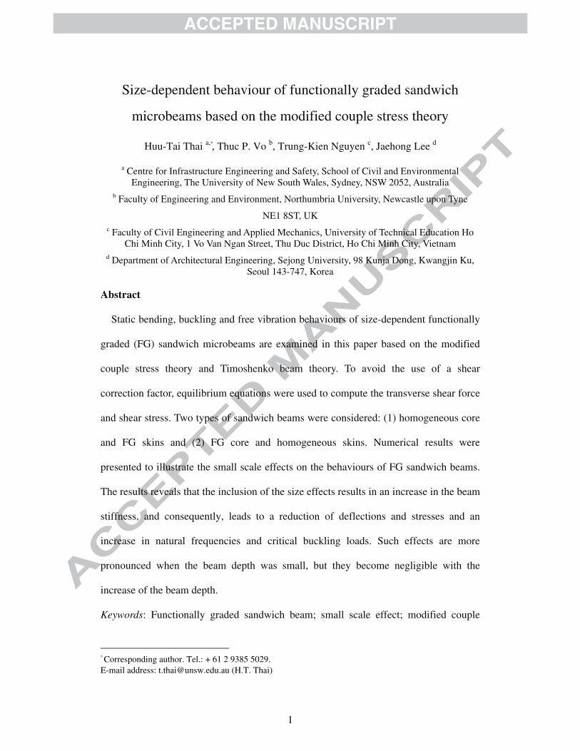
sandwich beams with a FG core and homogeneous skins. The material properties of the
beam such as Young’s modulus E , shear modulus G , Poisson's ratio ν and mass
density ρ are assumed to vary continuously through the thickness. The effective
material properties can be calculated using the Mori-Tanaka homogenization technique
[13-14, 16-18]. Based on Mori-Tanaka homogenization scheme, the effective bulk
modulus eK and shear modulus eG are given by [19]:
4
3
1
e m c
c mc mm
m m
K K VK KK K V
K G
− = −− ++
(10a)
9 8
6 12
1m m
m m
e m c
c mc mm K G
m m K G
G G VG GG G V
G G ++
− = −− ++
(10b)
where V is the volume fraction of the phase materials; the subscripts m and c
denote the metallic and ceramic phases, respectively. The effective Young’s modulus
and Poisson's ratio of a FG microbeam are related to eK and eG by:
( ) 9
3e e
e e
K GE z
K G=
+ (11a)
( ) 3 2
6 2e e
e e
K Gz
K Gν −=
+ (11b)
while the effective the mass density can be computed using the rule of mixture as:
( ) c c m mz V Vρ ρ ρ= + (12)
The volume fractions of the metal and ceramic constituents are related by:
1m cV V+ = (13)
According to the simple power law distribution, the volume fraction of the ceramic
constituent cV can be expressed as:

7
( ) [ ]
( ) [ ]
( ) [ ]
00 1
1 0
1 2
32 3
2 3
for ,
1 for ,
for ,
p
c
c
p
c
z hV z z h h
h h
V z z h h
z hV z z h h
h h
⎧ ⎛ ⎞−⎪ = ∈⎜ ⎟−⎪ ⎝ ⎠⎪ = ∈⎨⎪
⎛ ⎞−⎪ = ∈⎜ ⎟⎪ −⎝ ⎠⎩
(14)
for a sandwich beam with an homogeneous core and FG skins (type A), and
( ) [ ]
( ) [ ]
( ) [ ]
0 1
11 2
2 1
2 3
0 for ,
for ,
1 for ,
c
p
c
c
V z z h h
z hV z z h h
h h
V z z h h
⎧ = ∈⎪⎪ ⎛ ⎞−= ∈⎨ ⎜ ⎟−⎝ ⎠⎪⎪ = ∈⎩
(15)
for a sandwich beam with a FG core and homogeneous skins (type B), where p is the
power law index that governs the volume fraction gradation.
The linear elastic constitutive relations are:
( )xx xxE zσ ε= (16a)
( )( )2 1xz xz
E z
zσ γ
ν=
+⎡ ⎤⎣ ⎦ (16b)
( )( )
2
1xy xy
E zm
zχ
ν=+
� (16c)
Substituting Eq. (16) into Eq. (8), the stress resultants can be expressed in terms of
generalized displacements ( , ,u w ϕ ) as:
du d
N A Bdx dx
ϕ= + (17a)
du d
M B Ddx dx
ϕ= + (17b)
s
dwQ kA
dxϕ⎛ ⎞= +⎜ ⎟⎝ ⎠
(17c)

8
2
2
1
2 n
d d wY A
dx dx
ϕ⎛ ⎞= −⎜ ⎟
⎝ ⎠ (17d)
where
( ) ( ) ( )2, , 1, ,A
A B D z z E z dA= ∫ (18a)
( )( )2 1s A
E zA dA
zν=
+⎡ ⎤⎣ ⎦∫ (18b)
( )( )
2 2
2 1n sA
E zA dA A
zν= =
+⎡ ⎤⎣ ⎦∫� � (18c)
It should be noted that the shear stress xzσ computed from the constitutive equation Eq.
(16b) violates the zero transverse shear stress conditions on the top and bottom surfaces
of the beam, and thus requiring a shear correction factor. To avoid the use of the shear
correction factor, equilibrium equations are used herein. Based on equilibrium equations,
the transverse shear stress and shear force are given as follow [20]:
xz mQσ = � (19a)
dw
Q Hdx
ϕ⎛ ⎞= +⎜ ⎟⎝ ⎠ (19b)
The expressions for m� and H can be found in Nguyen et al. [20].
2.3. Analytical solutions
By substituting Eqs. (17) and (19) into Eq. (7), the governing equations of motion
can be rewritten in terms of generalized displacements ( , ,u w ϕ ) as:
2 2
0 12 2
d u dA B I u I
dx dx
ϕ ϕ+ = + ���� (20a)
2 3 4 2
0 02 3 4 24nAd d w d d w d w
H P q I wdx dx dx dx dx
ϕ ϕ⎛ ⎞ ⎛ ⎞+ + − − + =⎜ ⎟ ⎜ ⎟
⎝ ⎠ ⎝ ⎠�� (20b)

9
2 2 2 3
1 22 2 2 34nAd u d dw d d w
B D H I u Idx dx dx dx dx
ϕ ϕϕ ϕ⎛ ⎞⎛ ⎞+ − + + − = +⎜ ⎟⎜ ⎟⎝ ⎠ ⎝ ⎠���� (20c)
Based on Navier approach, the solutions of Eq. (20) for a simply supported beam are
assumed as:
( )
( )
( )
1
1
1
, cos
, sin
, cos
i tn
n
i tn
n
i tn
n
u x t U e x
w x t W e x
x t e x
ω
ω
ω
α
α
ϕ φ α
∞
=
∞
=
∞
=
=
=
=
∑
∑
∑
(21)
where 1i = − , /n Lα π= , and ω is the frequency of vibration. The transverse load
q is also expanded in Fourier series as:
( )1
sinnn
q x Q xα∞
=
=∑ (22)
where
0 0
00
for sinusoidal load of intensity
4for uniform load of intensity n
q qQ q
qnπ
⎧⎪= ⎨⎪⎩
(23)
Substituting Eqs. (21) and (22) into Eq. (20), the analytical solutions can be obtained
from the following equations:
11 13 11 13
2 222 23 0 22
13 23 33 13 33
0 0 0 0 0 0
0 0 1 0 0 0
0 0 0 0 0
n
n n
n
k k m m U
k k P m W Q
k k k m m
α ωφ
⎛ ⎞⎡ ⎤ ⎡ ⎤ ⎡ ⎤ ⎧ ⎫ ⎧ ⎫⎜ ⎟⎪ ⎪ ⎪ ⎪⎢ ⎥ ⎢ ⎥ ⎢ ⎥− − =⎨ ⎬ ⎨ ⎬⎜ ⎟⎢ ⎥ ⎢ ⎥ ⎢ ⎥ ⎪ ⎪ ⎪ ⎪⎜ ⎟⎢ ⎥ ⎢ ⎥ ⎢ ⎥⎣ ⎦ ⎣ ⎦ ⎣ ⎦ ⎩ ⎭ ⎩ ⎭⎝ ⎠
(24)
where
2 2 2 4 3 2
11 13 22 23 33
11 22 0 13 1 33 2
, , , ,4 4 4
, ,
n n nA A Ak A k B k H k H k H D
m m I m I m I
α α α α α α α⎛ ⎞= = = + = − = + +⎜ ⎟⎝ ⎠= = = =
(25)
3. Numerical results and discussions
10
Unless mentioned otherwise, simply supported FG sandwich microbeams composed
of aluminum Al ( 70mE = GPa, 0.30mν = , 2702mρ = kg/m3) and ceramic SiC ( cE =
427 GPa, 0.17cν = , 3100cρ = kg/m3) with length-to-thickness ratio / 10L h = are
considered. Since the material length scale parameter is not available for FG
microbeams, it was assumed to be equal to 15µm=� based on a reference value of a
homogeneous epoxy beam [21]. Two type of FG sandwich microbeams with four
different schemes including symmetric schemes (1-1-1) and (1-2-1) and non-symmetric
schemes (2-1-1) and (2-2-1) were considered. The following dimensionless forms are
used:
( )
( ) ( )
3
40 0
220
30
100 , ,12 2 2
120, , ,
mxx xx
mxz xz cr
m m
E h L h Lw w z z
q L q L
P Lh Lz z P
q L h E E h
σ σ
ρωσ σ ω
⎛ ⎞ ⎛ ⎞= =⎜ ⎟ ⎜ ⎟⎝ ⎠ ⎝ ⎠
= = = (26)
3.1. Verification studies
So far there are no available results for FG sandwich microbeams. Therefore, in
order to verify validity of the present results, two cases of verification were carried out:
(1) FG microbeams with the size effect ( ≠� 0) and (2) FG sandwich beams without the
size effect ( =� 0).
Tables 1 and 2 contain dimensionless deflections and fundamental frequencies of FG
microbeams, respectively. The obtained results were compared with those reported by
Simsek and Reddy [17] using the TBT. An excellent agreement between the results was
found for all values of power law index p , dimensionless material length scale
parameter /h � and length-to-thickness ratio /L h . It is worth noting that the results
given in Tables 1 and 2 were obtained based on the constitutive equations derived from
a three-dimensional (3D) relation as:

11
( ) ( )( ) ( )
1
1 1 2xx xx
E z z
z z
νσ ε
ν ν−⎡ ⎤⎣ ⎦=
+ −⎡ ⎤ ⎡ ⎤⎣ ⎦ ⎣ ⎦ (27)
To further verify the present results, Table 3 shows the comparison of dimensionless
critical buckling loads predicted by the present work and Simsek and Reddy [18] using
the TBT. For this comparison, the following material properties were used: steel
SUS304 ( 210mE = GPa, 0.3177mν = , 8166mρ = kg/m3) and alumina Al2O3 ( cE =390
GPa, 0.3cν = , 3960cρ = kg/m3). It can be seen that obtained results agree well with
the solutions given by Simsek and Reddy [18] confirming the validity of the present
results for the analysis of FG microbeams.
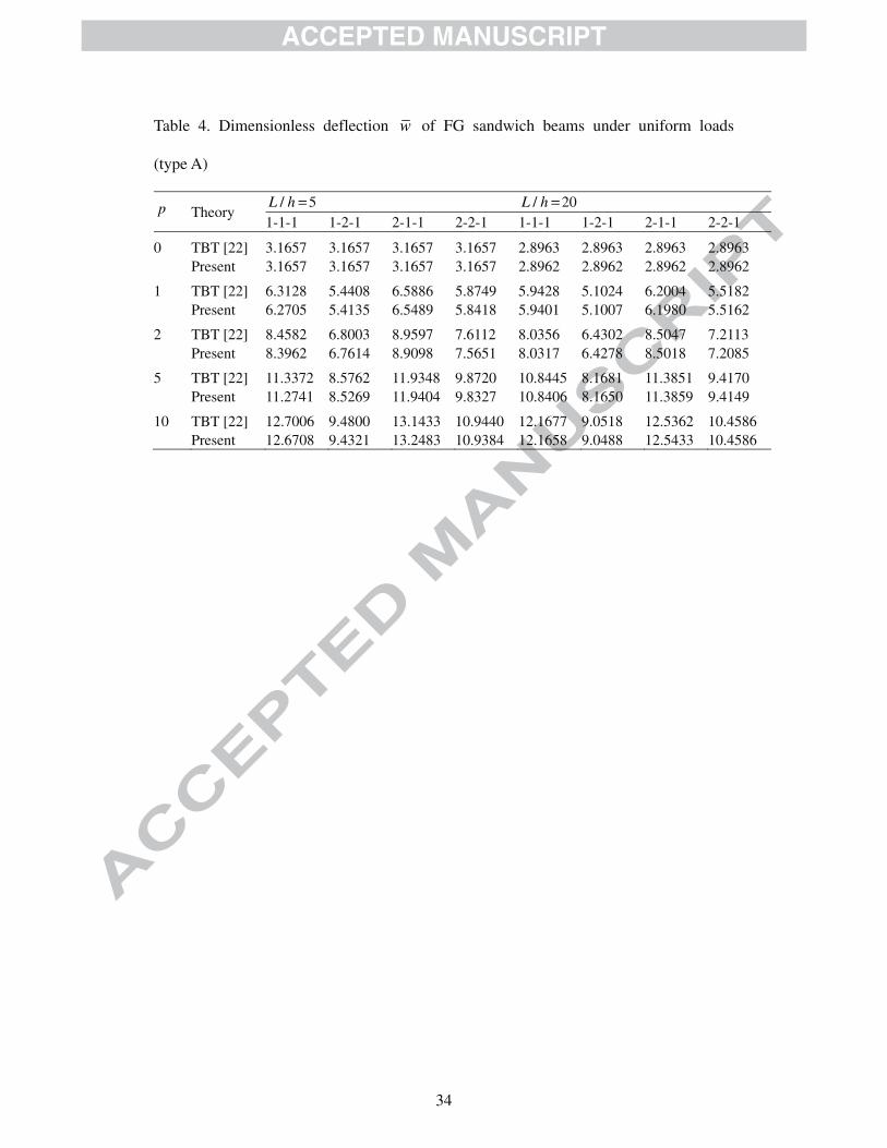
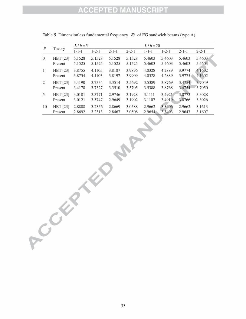
To verify for FG sandwich beams without the size effect ( =� 0), a FG sandwich
beam (type A) with the following material properties were considered: Aluminum Al
( 70mE = GPa, 0.3mν = , 2702mρ = kg/m3) and Alumina Al2O3 ( cE = 380 GPa,
0.3cν = , 3960cρ = kg/m3). In this verification, the effective material properties were
evaluated using the rule of mixture. Dimensionless deflections, fundamental frequencies
and critical buckling loads obtained in this study were compared with those generated
by Vo et al. [22-23] using the TBT and HBT in Tables 4-6. Again, the obtained results
are very close to the TBT solutions [22] and HBT solutions [23] for FG sandwich beams
with different schemes and values of p and /L h .
3.2. Parameter studies
Parameter studies were carried out to investigate the effects of the material length
scale parameter � and power law index p on the deflection, stress, frequency and
critical buckling load of simply supported FG sandwich microbeams. The results of
both the present size-dependent model ( 0≠� ) and classical model ( 0=� ) are given
Tables 7-11 for two types of FG sandwich beams with different values of /h � and p .

12
It can be observed from Tables 7-11 that, for the case of homogeneous beams ( 0p = ),
all sandwich schemes give the same results for the type A but different results for the
type B. This is due to the fact that when the power law index p was equal to 0, the
volume fraction of the ceramic phase cV will be equal to 1.0 for all layers of the type A
(see Eq. (14)). Therefore, the type A sandwich beam behaves like an isotropic beam
made of the ceramic constituent.
For the bending analysis, a FG sandwich microbeam subjected to uniform loads was
considered. Dimensionless deflections, normal stresses and transverse shear stresses are
respectively tabulated in Tables 7-9. The variations of the normal and transverse shear
stresses through the thickness were also plotted in Figs. 2-5, whilst the variation of the
deflection with respect to /h � was illustrated in Fig. 6. In general, the inclusion of the
size effect in the analysis ( 0≠� ) results in reductions of both the deflection and stresses.
These reductions become remarkably significant when the beam depth was small (e.g.,
h = � ) and can be negligible when the beam depth was larger. This statement can be
clearly seen in Fig. 6 where the size effect almost diminishes at the beam depth greater
than twenty times the material length scale parameter ( 20h > � ). For the type A, the size
effect of FG beams ( 0p ≠ ) was more pronounced than the homogeneous one ( 0p = )
as indicated in Fig. 7 in which the deflection ratio was defined as the ratio of the
deflection predicted by the classical model ( 0=� ) to that predicted by the present size-
dependent model ( 0≠� ).
As shown in Fig. 2(a) and Fig. 2(b), the distribution of the normal stress of the type A
sandwich beams was symmetric through the middle plane for symmetric schemes (1-1-1)
and (1-2-1) due to the symmetric configuration. It was also noticed from Fig. 2 that the
maximum value of the normal stress in FG beams was not located at the top or bottom

13
surface of the beam as in the case of homogeneous beams. It is important to note that
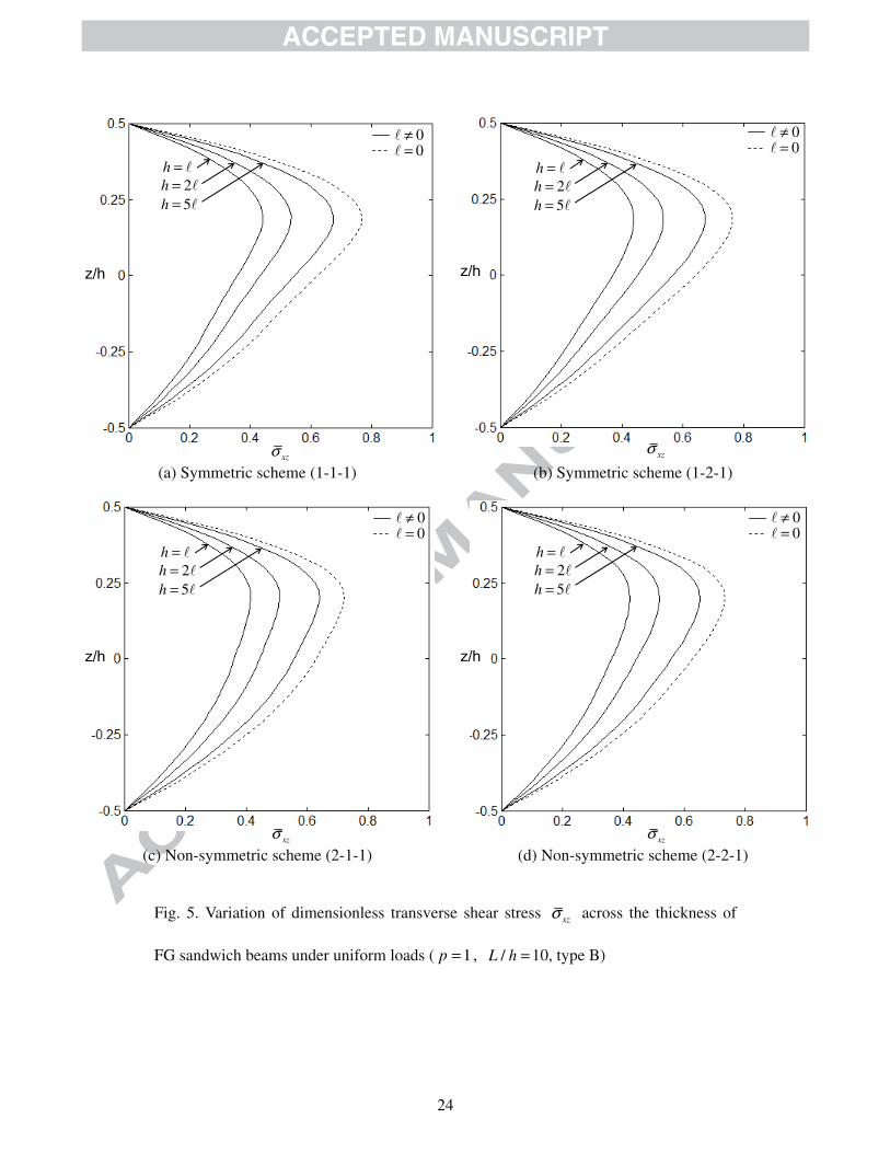
the transverse shear stress obtained in the present work was based on equilibrium
equations (see Eq. (19)) and thus satisfying the stress-free boundary conditions on the
top and bottom surfaces of the beam as shown in Figs. 4 and 5.
The effects of the material length scale parameter � and power law index p on
dimensionless fundamental frequencies are given in Table 10 and illustrated in Fig. 8.
The results show that the dimensionless frequencies of the beam reduce by the increase
of the beam depth, and this reduction is dramatic when 5h < � and insignificant when
10h > � (see Fig. 8). In other words, the effect of small scale on vibration behaviour is
similar to that on bending behaviour, i.e. it is considerable only when the beam depth
was at the micron scale. It is also observed from Table 10 and Fig. 8 that, for a constant
beam depth, increasing the power law index p results in a reduction of dimensionless
frequencies due to the low portion of ceramic in comparison with the metal phase as
shown in Fig. 9. The effect of the material length scale parameter � and power law
index p on higher modes was plotted in Fig. 10 for the type A sandwich beams with
the (1-1-1) scheme. In this figure, the frequency ratio was defined as the ratio of the
frequency predicted by the present size-dependent model ( 0≠� ) to that predicted by
the classical model ( 0=� ). It is clearly seen from Fig. 10 that the effect of � on
frequency is similar for each mode.
Table 11 and Fig. 11 show the influences of the material length scale parameter �
and power law index p on the dimensionless critical buckling load. It can be seen that
the variation of the critical buckling load with respect to � and p exhibits similar
trends with the variation of the frequency observed in the free vibration analysis. It
means that the critical buckling load decrease with the increase of � and p , and the

14
smaller the beam depth, the more significant the reduction.
4. Conclusions
Based on the modified couple stress theory and the TBT, the static bending, free
vibration and buckling behaviours of FG sandwich microbeams have been investigated.
The material properties of the FG sandwich microbeams which were assumed to vary
continuously through the beam thickness were estimated using the Mori-Tanaka
homogenization approach. Closed-form solutions for deflections, stresses, frequencies
and critical buckling loads were presented for FG sandwich microbeams with simply
supported boundary conditions. The validity of the present solutions has been verified
for various case of with and without the material length scale parameter. Numerical
results indicate that the inclusion of the small scale effect makes the beam stiffer, and
consequently, leads to a reduction of both deflection and stresses and an increase in the
critical buckling load and natural frequency. The small scale effect is remarkably
significant at the micron scale and thus should be considered in the analysis of FG
sandwich microbeams.
Acknowledgements
The authors gratefully acknowledge the financial support from the Basic Research
Laboratory Program of the National Research Foundation of Korea (NRF) funded by
the Ministry of Education, Science and Technology (2010-0019373 and
2012R1A2A1A01007405) and by Vietnam National Foundation for Science and
Technology Development (NAFOSTED) under Grant No. 107.02-2012.07.
References
[1] Fu Y, Du H, Zhang S. Functionally graded TiN/TiNi shape memory alloy films.

15
Materials Letters 2003;57(20):2995-2999.
[2] Rahaeifard M, Kahrobaiyan MH, Ahmadian MT. Sensitivity analysis of atomic
force microscope cantilever made of functionally graded materials. In: 3rd
International Conference on Micro- and Nanosystems 2009;DETC2009-86254:539-
544.
[3] Witvrouw A, Mehta A. The use of functionally graded poly-SiGe layers for MEMS
applications. Materials Science Forum 2005;492-493:255-260.
[4] Chong ACM, Yang F, Lam DCC, Tong P. Torsion and bending of micron-scaled
structures. Journal of Materials Research 2001;16(04):1052-1058.
[5] Fleck NA, Muller GM, Ashby MF, Hutchinson JW. Strain gradient plasticity: theory
and experiment. Acta Metallurgica et Materialia 1994;42(2):475-487.
[6] Stolken JS, Evans AG. A microbend test method for measuring the plasticity length
scale. Acta Materialia 1998;46(14):5109-5115.
[7] Yang F, Chong ACM, Lam DCC, Tong P. Couple stress based strain gradient theory
for elasticity. International Journal of Solids and Structures 2002;39(10):2731-2743.
[8] Asghari M, Ahmadian MT, Kahrobaiyan MH, Rahaeifard M. On the size-dependent
behavior of functionally graded micro-beams. Materials & Design
2010;31(5):2324-2329.
[9] Reddy JN. Microstructure-dependent couple stress theories of functionally graded
beams. Journal of the Mechanics and Physics of Solids 2011;59(11):2382-2399.
[10] Nateghi A, Salamat-talab M, Rezapour J, Daneshian B. Size dependent buckling
analysis of functionally graded micro beams based on modified couple stress theory.
Applied Mathematical Modelling 2012;36(10):4971-4987.
[11] Akgoz B, Civalek O. Free vibration analysis of axially functionally graded tapered

16
Bernoulli–Euler microbeams based on the modified couple stress theory. Composite
Structures 2013;98:314-322.
[12] Asghari M, Rahaeifard M, Kahrobaiyan MH, Ahmadian MT. The modified couple
stress functionally graded Timoshenko beam formulation. Materials & Design
2011;32(3):1435-1443.
[13] Ke LL, Wang YS. Size effect on dynamic stability of functionally graded
microbeams based on a modified couple stress theory. Composite Structures
2011;93(2):342-350.
[14] Simsek M, Kocaturk T, Akbas SD. Static bending of a functionally graded
microscale Timoshenko beam based on the modified couple stress theory.
Composite Structures 2013;95:740-747.
[15] Salamat-talab M, Nateghi A, Torabi J. Static and dynamic analysis of third-order
shear deformation FG micro beam based on modified couple stress theory.
International Journal of Mechanical Sciences 2012;57(1):63-73.
[16] Zhang B, He Y, Liu D, Gan Z, Shen L. Size-dependent functionally graded beam
model based on an improved third-order shear deformation theory. European
Journal of Mechanics - A/Solids 2014;47:211-230.
[17] Simsek M, Reddy JN. Bending and vibration of functionally graded microbeams
using a new higher order beam theory and the modified couple stress theory.
International Journal of Engineering Science 2013;64:37-53.
[18] Simsek M, Reddy JN. A unified higher order beam theory for buckling of a
functionally graded microbeam embedded in elastic medium using modified couple
stress theory. Composite Structures 2013;101:47-58.
[19] Mori T, Tanaka K. Average stress in matrix and average elastic energy of materials
17
with misfitting inclusions. Acta Metallurgica 1973;21(5):571-574.
[20] Nguyen TK, Vo TP, Thai HT. Static and free vibration of axially loaded functionally
graded beams based on the first-order shear deformation theory. Composites Part B:
Engineering 2013;55:147-157.
[21] Ansari R, Gholami R, Sahmani S. Free vibration analysis of size-dependent
functionally graded microbeams based on the strain gradient Timoshenko beam
theory. Composite Structures 2011;94(1):221-228.
[22] Vo TP, Thai HT, Nguyen TK, Inam F, Lee J. Static behaviour of functionally graded
sandwich beams using a quasi-3D theory. Composites Part B: Engineering
2015;68:59-74.
[23] Vo TP, Thai HT, Nguyen TK, Maheri A, Lee J. Finite element model for vibration
and buckling of functionally graded sandwich beams based on a refined shear
deformation theory. Engineering Structures 2014;64:12-22.
18
Figure Captions
Fig. 1. Geometry and coordinate of a FG sandwich beam
Fig. 2. Variation of dimensionless normal stress xσ across the thickness of FG
sandwich beams under uniform loads ( 1p = , /L h =10, type A)
Fig. 3. Variation of dimensionless normal stress xσ across the thickness of FG
sandwich beams under uniform loads ( 1p = , /L h =10, type B)
Fig. 4. Variation of dimensionless transverse shear stress xzσ across the thickness of
FG sandwich beams under uniform loads ( 1p = , /L h =10, type A)
Fig. 5. Variation of dimensionless transverse shear stress xzσ across the thickness of
FG sandwich beams under uniform loads ( 1p = , /L h =10, type B)
Fig. 6. Effect of the material length scale parameter � on the dimensionless deflection
w of (1-2-1) FG sandwich beams under uniform loads ( 1p = , /L h =10)
Fig. 7. Effect of the power law index p on the deflections of FG sandwich beams
under uniform loads (type A, /L h =10)
Fig. 8. Effects of the material length scale parameter � and the power law index p
on the dimensionless frequency ω of (1-1-1) FG sandwich beams ( /L h =10, type A)
Fig. 9. Variation of the volume fraction of the ceramic phase cV across the thickness
Fig. 10. Effect of the material length scale parameter � on higher frequencies of (1-1-1)
FG sandwich beams ( /L h =10, type A)
Fig. 11. Effects of the material length scale parameter � and the power law index p
on the dimensionless buckling load crP of (1-1-1) FG sandwich beams ( /L h =10)

19
Table Captions
Table 1. Dimensionless deflection w of FG microbeams under uniform loads
Table 2. Dimensionless fundamental frequency ω of FG microbeams
Table 3. Dimensionless critical buckling load crP of FG microbeams ( /L h =20)
Table 4. Dimensionless deflection w of FG sandwich beams under uniform loads
(type A)
Table 5. Dimensionless fundamental frequency ω of FG sandwich beams (type A)
Table 6. Dimensionless critical buckling load crP of FG sandwich beams (type A)
Table 7. Dimensionless deflection w of FG sandwich microbeams under uniform
loads ( /L h =10)
Table 8. Dimensionless normal stress ( )/ 2x hσ of FG sandwich microbeams under
uniform loads ( /L h =10)
Table 9. Dimensionless transverse shear stress ( )0xzσ of FG sandwich microbeams
under uniform loads ( /L h =10)
Table 10. Dimensionless fundamental frequency ω of FG sandwich microbeams
Table 11. Dimensionless critical buckling load crP of FG sandwich microbeams

20
Fig. 1. Geometry and coordinate of a FG sandwich beam
h
z
L b
x
y
h0=-h/2
z
h1
h3=h/2h2
h0=-h/2
z
h1
h3=h/2
h2
b
a) Type A
b) Type B
MetalCeramic
Metal
Ceramic
MetalMetal
Ceramic
Ceramic

21
(a) Symmetric scheme (1-1-1) (b) Symmetric scheme (1-2-1)
(c) Non-symmetric scheme (2-1-1) (d) Non-symmetric scheme (2-2-1)
Fig. 2. Variation of dimensionless normal stress xxσ across the thickness of FG
sandwich beams under uniform loads ( 1p = , /L h =10, type A)
xxσ
h = �
z/h
0≠�0=�
2h = �
5h = �
xxσ
0≠�0=�
z/h
h = �2h = �
5h = �
xxσ
z/h
0≠�0=�
h = �2h = �
5h = �
xxσ
z/h
0≠�0=�
h = �2h = �
5h = �

22
(a) Symmetric scheme (1-1-1) (b) Symmetric scheme (1-2-1)
(c) Non-symmetric scheme (2-1-1) (d) Non-symmetric scheme (2-2-1)
Fig. 3. Variation of dimensionless normal stress xxσ across the thickness of FG
sandwich beams under uniform loads ( 1p = , /L h =10, type B)
xxσ
z/h
0≠�0=�
h = �2h = �
5h = �
xxσ
z/h
0≠�0=�
h = �2h = �
5h = �
xxσ
z/h
0≠�0=�
h = �2h = �
5h = �
xxσ
z/h
0≠�0=�
h = �2h = �
5h = �

23
(a) Symmetric scheme (1-1-1) (b) Symmetric scheme (1-2-1)
(c) Non-symmetric scheme (2-1-1) (d) Non-symmetric scheme (2-2-1)
Fig. 4. Variation of dimensionless transverse shear stress xzσ across the thickness of
FG sandwich beams under uniform loads ( 1p = , /L h =10, type A)
xzσ
h = �
z/h
0≠�0=�
2h = �
5h = �
xzσ
h = �
0≠�0=�
2h = �
5h = �
z/h
xzσ
h = �
z/h
0≠�0=�
2h = �
5h = �
xzσ
h = �
z/h
0≠�0=�
2h = �
5h = �
24
(a) Symmetric scheme (1-1-1) (b) Symmetric scheme (1-2-1)
(c) Non-symmetric scheme (2-1-1) (d) Non-symmetric scheme (2-2-1)
Fig. 5. Variation of dimensionless transverse shear stress xzσ across the thickness of
FG sandwich beams under uniform loads ( 1p = , /L h =10, type B)
xzσ
h = �
z/h
0≠�0=�
2h = �
5h = �
xzσ
h = �
z/h
0≠�0=�
2h = �
5h = �
xzσ
h = �
z/h
0≠�0=�
2h = �
5h = �
xzσ
h = �
z/h
0≠�0=�
2h = �
5h = �

25
Fig. 6. Effect of the material length scale parameter � on the dimensionless deflection
w of (1-2-1) FG sandwich beams under uniform loads ( 1p = , /L h =10)
0
0.1
0.2
0.3
0.4
0.5
0.6
0.7
0 10 20 30 40 50
w
/h �
Type A
Type B
0≠�0=�

26
Fig. 7. Effect of the power law index p on the deflections of FG sandwich beams
under uniform loads (type A, /L h =10)
5
6
7
8
9
10
11
12
13
0 5 10 15 20p
2-2-1
1-2-1
2-1-1
1-1-1
Def
lect
ion
ratio

27
Fig. 8. Effects of the material length scale parameter � and the power law index p
on the dimensionless frequency ω of (1-1-1) FG sandwich beams ( /L h =10, type A)
0
2
4
6
8
10
12
14
16
0 10 20 30 40 50
p=0
p=1
p=10
ω
/h �

FFigg. 9.. Va
(
aria
a) T
ation
Typ
n o
pe A
of th
A
he vvoluumee frracttionn off thee ceerammicc phhasee VcV
(b
acr
b) T
ross
Type
s the
e B
e th
B
hickkneess

29
Fig. 10. Effect of the material length scale parameter � on higher frequencies of (1-1-1)
FG sandwich beams ( /L h =10, type A)
1
1.5
2
2.5
3
3.5
0 5 10 15 20
Mode 1
Mode 2
/h �
p=1
p=0
Fre
quen
cy r
atio

30
(a) Type A
(b) Type B
Fig. 11. Effects of the material length scale parameter � and the power law index p
on the dimensionless buckling load crP of (1-1-1) FG sandwich beams ( /L h =10)
crP
p/h �
p
crP
/h �

31
Table 1. Dimensionless deflection w of FG microbeams under uniform loads
/h � Theory /L h =10 /L h =100
p =0.3 1 3 10 p =0.3 1 3 10
1 TBT [17] 0.0592 0.0902 0.1330 0.1797 0.0565 0.0859 0.1262 0.1698 Present 0.0594 0.0902 0.1330 0.1789 0.0567 0.0860 0.1262 0.1691
2 TBT [17] 0.1537 0.2292 0.3175 0.4095 0.1496 0.2228 0.3069 0.3940 Present 0.1544 0.2293 0.3173 0.4058 0.1504 0.2228 0.3067 0.3902
4 TBT [17] 0.2603 0.3794 0.4928 0.6093 0.2543 0.3699 0.4778 0.5878 Present 0.2620 0.3794 0.4925 0.6016 0.2559 0.3699 0.4774 0.5800
8 TBT [17] 0.3154 0.4542 0.5723 0.6946 0.3081 0.4430 0.5550 0.6702 Present 0.3177 0.4542 0.5719 0.6845 0.3105 0.4430 0.5545 0.6601

32
Table 2. Dimensionless fundamental frequency ω of FG microbeams
/h � Theory /L h =10 /L h =100
p =0.3 1 3 10 p =0.3 1 3 10
1 TBT [17] 12.6058 10.3982 8.7110 7.5835 12.9533 10.6960 8.9820 7.8325 Present 12.5893 10.3984 8.7145 7.6023 12.9355 10.6961 8.9856 7.8536
2 TBT [17] 7.8233 6.5211 5.6383 5.0237 7.9640 6.6461 5.7623 5.1442 Present 7.8062 6.5212 5.6408 5.0473 7.9460 6.6463 5.7648 5.1697
4 TBT [17] 6.0115 5.0692 4.5256 4.1184 6.1096 5.1583 4.6187 4.2118 Present 5.9931 5.0693 4.5275 4.1450 6.0904 5.1584 4.6207 4.2403
8 TBT [17] 5.4617 4.6327 4.1995 3.8573 5.5500 4.7135 4.2854 3.9444 Present 5.4418 4.6329 4.2015 3.8857 5.5293 4.7136 4.2875 3.9747

33
Table 3. Dimensionless critical buckling load crP of FG microbeams ( /L h =20)
/h � Theory p =0 0.2 0.5 1 2 5 10 Metal
1 TBT [18] 101.7143 91.2490 82.5580 74.9674 68.1271 61.6033 58.4786 54.1609 Present 101.6569 90.8166 82.4485 74.9253 68.0883 61.5695 58.4613 55.0508
2 TBT [18] 39.2016 34.9260 31.5537 28.7950 26.4790 24.2657 23.0415 20.9550 Present 39.1884 34.7306 31.5064 28.7854 26.4701 24.2585 23.0436 21.5161
4 TBT [18] 23.4706 20.7526 18.7187 17.1759 15.9986 14.8699 14.1239 12.5989 Present 23.4637 20.5807 18.6832 17.1709 15.9938 14.8665 14.1281 13.1204
8 TBT [18] 19.5314 17.2035 15.5047 14.2664 13.3741 12.5171 11.8909 10.5065 Present 19.5257 17.0381 15.4722 14.2623 13.3702 12.5144 11.8953 11.0235
34
Table 4. Dimensionless deflection w of FG sandwich beams under uniform loads
(type A)
p Theory /L h =5 /L h =20
1-1-1 1-2-1 2-1-1 2-2-1 1-1-1 1-2-1 2-1-1 2-2-1
0 TBT [22] 3.1657 3.1657 3.1657 3.1657 2.8963 2.8963 2.8963 2.8963 Present 3.1657 3.1657 3.1657 3.1657 2.8962 2.8962 2.8962 2.8962
1 TBT [22] 6.3128 5.4408 6.5886 5.8749 5.9428 5.1024 6.2004 5.5182 Present 6.2705 5.4135 6.5489 5.8418 5.9401 5.1007 6.1980 5.5162
2 TBT [22] 8.4582 6.8003 8.9597 7.6112 8.0356 6.4302 8.5047 7.2113 Present 8.3962 6.7614 8.9098 7.5651 8.0317 6.4278 8.5018 7.2085
5 TBT [22] 11.3372 8.5762 11.9348 9.8720 10.8445 8.1681 11.3851 9.4170 Present 11.2741 8.5269 11.9404 9.8327 10.8406 8.1650 11.3859 9.4149
10 TBT [22] 12.7006 9.4800 13.1433 10.9440 12.1677 9.0518 12.5362 10.4586 Present 12.6708 9.4321 13.2483 10.9384 12.1658 9.0488 12.5433 10.4586
35
Table 5. Dimensionless fundamental frequency ω of FG sandwich beams (type A)
p Theory /L h =5 /L h =20
1-1-1 1-2-1 2-1-1 2-2-1 1-1-1 1-2-1 2-1-1 2-2-1
0 HBT [23] 5.1528 5.1528 5.1528 5.1528 5.4603 5.4603 5.4603 5.4603 Present 5.1525 5.1525 5.1525 5.1525 5.4603 5.4603 5.4603 5.4603
1 HBT [23] 3.8755 4.1105 3.8187 3.9896 4.0328 4.2889 3.9774 4.1602 Present 3.8754 4.1103 3.8197 3.9909 4.0328 4.2889 3.9775 4.1602
2 HBT [23] 3.4190 3.7334 3.3514 3.5692 3.5389 3.8769 3.4754 3.7049 Present 3.4178 3.7327 3.3510 3.5705 3.5388 3.8768 3.4754 3.7050
5 HBT [23] 3.0181 3.3771 2.9746 3.1928 3.1111 3.4921 3.0773 3.3028 Present 3.0121 3.3747 2.9649 3.1902 3.1107 3.4919 3.0766 3.3026
10 HBT [23] 2.8808 3.2356 2.8669 3.0588 2.9662 3.3406 2.9662 3.1613 Present 2.8692 3.2313 2.8467 3.0508 2.9654 3.3403 2.9647 3.1607

36
Table 6. Dimensionless critical buckling load crP of FG sandwich beams (type A)
p Theory /L h =5 /L h =20
1-1-1 1-2-1 2-1-1 2-2-1 1-1-1 1-2-1 2-1-1 2-2-1
0 HBT [23] 48.5959 48.5959 48.5959 48.5959 53.2364 53.2364 53.2364 53.2364 Present 48.5904 48.5904 48.5904 48.5904 53.2363 53.2363 53.2363 53.2363
1 HBT [23] 24.5596 28.4447 23.5246 26.3611 25.9588 30.2307 24.8796 27.9540 Present 24.5545 28.4375 23.5102 26.3540 25.9585 30.2303 24.8783 27.9533
2 HBT [23] 18.3587 22.7863 17.3249 20.3750 19.3116 23.9900 18.1404 21.3927 Present 18.3430 22.7742 17.2845 20.3559 19.1989 23.9892 18.1372 21.3910
5 HBT [23] 13.7212 18.0914 13.0270 15.7307 14.2284 18.8874 13.5523 16.3834 Present 13.6628 18.0624 12.8973 15.6638 14.2245 18.8854 13.5430 16.3783
10 HBT [23] 12.2605 16.3783 11.8370 14.1995 12.6819 17.0443 12.3084 14.7525 Present 12.1562 16.3299 11.6216 14.0798 12.6749 17.0410 12.2931 14.7438

37
Table 7. Dimensionless deflection w of FG sandwich microbeams under uniform
loads ( /L h =10)
p /h � Type A Type B 1-1-1 1-2-1 2-1-1 2-2-1 1-1-1 1-2-1 2-1-1 2-2-1
0 1 0.0364 0.0364 0.0364 0.0364 0.0538 0.0485 0.0684 0.0589 2 0.0960 0.0960 0.0960 0.0960 0.1586 0.1404 0.2007 0.1745 5 0.1811 0.1811 0.1811 0.1811 0.3606 0.3085 0.4592 0.4023 0=� 0.2183 0.2183 0.2183 0.2183 0.4771 0.4004 0.6105 0.5368
1 1 0.0648 0.0552 0.0707 0.0606 0.0752 0.0789 0.0912 0.0915 2 0.1966 0.1645 0.2125 0.1816 0.2164 0.2233 0.2523 0.2523 5 0.4704 0.3809 0.5005 0.4253 0.4757 0.4751 0.5215 0.5166 0=� 0.6417 0.5095 0.6762 0.5727 0.6180 0.6065 0.6564 0.6471
2 1 0.0734 0.0598 0.0823 0.0673 0.0804 0.0878 0.0965 0.1003 2 0.2279 0.1825 0.2520 0.2064 0.2292 0.2442 0.2630 0.2704 5 0.5750 0.4434 0.6184 0.5079 0.4968 0.5079 0.5317 0.5357 0=� 0.8120 0.6106 0.8577 0.7055 0.6409 0.6411 0.6621 0.6605
5 1 0.0824 0.0643 0.0953 0.0741 0.0856 0.0969 0.1016 0.1092 2 0.2594 0.1996 0.2927 0.2307 0.2407 0.2636 0.2726 0.2874 5 0.6777 0.5041 0.7292 0.5876 0.5131 0.5318 0.5402 0.5508 0=� 0.9811 0.7126 1.0217 0.8358 0.6561 0.6611 0.6661 0.6688
10 1 0.0866 0.0662 0.1017 0.0773 0.0879 0.1010 0.1037 0.1132 2 0.2736 0.2068 0.3112 0.2412 0.2457 0.2722 0.2768 0.2951 5 0.7187 0.5292 0.7710 0.6195 0.5192 0.5402 0.5439 0.5573 0=� 1.0471 0.7562 1.0767 0.8875 0.6605 0.6657 0.6676 0.6717

38
Table 8. Dimensionless normal stress ( )/ 2xx hσ of FG sandwich microbeams under
uniform loads ( /L h =10)
p /h � Type A Type B 1-1-1 1-2-1 2-1-1 2-2-1 1-1-1 1-2-1 2-1-1 2-2-1
0 1 1.1897 1.1897 1.1897 1.1897 1.3133 1.2799 1.4004 1.3430 2 3.2581 3.2581 3.2581 3.2581 4.0266 3.8497 4.3489 4.1577 5 6.2125 6.2125 6.2125 6.2125 9.2532 8.5471 10.1054 9.7009 0=� 7.5000 7.5000 7.5000 7.5000 12.2679 11.1154 13.4723 12.9731
1 1 0.3534 0.2998 0.3437 0.2982 1.5050 1.5941 1.6810 1.7411 2 1.1080 0.9255 1.0704 0.9259 4.5615 4.7380 4.9548 5.0826 5 2.6760 2.1642 2.5460 2.1901 10.1676 10.2157 10.4212 10.5707 0=� 3.6567 2.8994 3.4458 2.9543 13.2433 13.0729 13.1592 13.2776
2 1 0.4001 0.3256 0.3900 0.3249 1.5401 1.6692 1.7446 1.8534 2 1.2858 1.0286 1.2411 1.0331 4.6518 4.9193 5.0863 5.3173 5 3.2745 2.5223 3.0791 2.5673 10.2469 10.3913 10.4768 10.7144 0=� 4.6321 3.4799 4.2790 3.5722 13.2566 13.1541 13.0918 13.2520
5 1 0.4470 0.3500 0.4391 0.3506 1.5744 1.7552 1.8089 1.9830 2 1.4611 1.1256 1.4131 1.1348 4.7336 5.1052 5.2202 5.5833 5 3.8577 2.8698 3.5674 2.9224 10.2791 10.4900 10.5474 10.9026 0=� 5.5956 4.0640 5.0114 4.1654 13.1899 13.0937 13.0577 13.2919
10 1 0.4672 0.3601 0.4616 0.3615 1.5887 1.7977 1.8385 2.0465 2 1.5383 1.1656 1.4901 1.1779 4.7730 5.2053 5.2799 5.7269 5 4.0876 3.0130 3.7466 3.0610 10.2847 10.5345 10.5884 11.0218 0=� 5.9673 4.3131 5.2514 4.3956 13.1423 13.0621 13.0613 13.3690

39
Table 9. Dimensionless transverse shear stress ( )0xzσ of FG sandwich microbeams
under uniform loads ( /L h =10)
p /h � Type A Type B 1-1-1 1-2-1 2-1-1 2-2-1 1-1-1 1-2-1 2-1-1 2-2-1
0 1 0.3334 0.3334 0.3334 0.3334 0.4550 0.3969 0.1189 0.5486 2 0.4157 0.4157 0.4157 0.4157 0.5483 0.4814 0.1432 0.6593 5 0.5375 0.5375 0.5375 0.5375 0.7322 0.6397 0.1920 0.8826 0=� 0.5951 0.5951 0.5951 0.5951 0.8444 0.7314 0.2226 1.0225
1 1 0.4571 0.4066 0.5352 0.4462 0.4503 0.4594 0.1845 0.3896 2 0.5450 0.4880 0.6401 0.5342 0.5465 0.5610 0.2267 0.4795 5 0.7311 0.6525 0.8578 0.7153 0.7281 0.7435 0.2999 0.6324 0=� 0.8527 0.7549 0.9970 0.8300 0.8353 0.8462 0.3404 0.7151
2 1 0.5174 0.4302 0.6646 0.4986 0.3432 0.3739 0.2092 0.2706 2 0.6103 0.5114 0.7885 0.5911 0.4178 0.4588 0.2583 0.3352 5 0.8224 0.6871 1.0612 0.7953 0.5563 0.6068 0.3406 0.4400 0=� 0.9731 0.8048 1.2477 0.9350 0.6372 0.6885 0.3851 0.4947
5 1 0.6327 0.4634 0.9194 0.5965 0.2086 0.2421 0.2359 0.2460 2 0.7410 0.5466 1.0884 0.7026 0.2551 0.2994 0.2923 0.3070 5 1.0012 0.7367 1.4692 0.9484 0.3393 0.3946 0.3847 0.4008 0=� 1.1984 0.8731 1.7361 1.1271 0.3876 0.4451 0.4331 0.4476
10 1 0.7220 0.4856 1.1073 0.6723 0.1974 0.2353 0.2484 0.2651 2 0.8448 0.5711 1.3137 0.7911 0.2417 0.2917 0.3091 0.3315 5 1.1423 0.7707 1.7746 1.0690 0.3214 0.3839 0.4063 0.4319 0=� 1.3749 0.9203 2.0917 1.2765 0.3659 0.4299 0.4556 0.4792

40
Table 10. Dimensionless fundamental frequency ω of FG sandwich microbeams
p /h � Type A Type B 1-1-1 1-2-1 2-1-1 2-2-1 1-1-1 1-2-1 2-1-1 2-2-1
0 1 15.8337 15.8337 15.8337 15.8337 13.3095 13.9514 11.9338 12.7753 2 9.7550 9.7550 9.7550 9.7550 7.7532 8.1976 6.9657 7.4227 5 7.1017 7.1017 7.1017 7.1017 5.1423 5.5301 4.6051 4.8888 0=� 6.4696 6.4696 6.4696 6.4696 4.4704 4.8538 3.9939 4.2322
1 1 12.1351 13.0839 11.6506 12.5289 11.3842 11.1113 10.4206 10.3895 2 6.9695 7.5771 6.7208 7.2352 6.7072 6.6030 6.2642 6.2541 5 4.5053 4.9786 4.3793 4.7270 4.5238 4.5266 4.3567 4.3700 0=� 3.8573 4.3050 3.7677 4.0735 3.9688 4.0063 3.8831 3.9046
2 1 11.4924 12.6357 10.8903 11.9664 11.0444 10.5946 10.1596 9.9653 2 6.5213 7.2328 6.2251 6.8311 6.5419 6.3489 6.1534 6.0683 5 4.1057 4.6407 3.9734 4.3548 4.4428 4.4022 4.3269 4.3110 0=� 3.4550 3.9543 3.3738 3.6950 3.9117 3.9182 3.8771 3.8823
5 1 10.9287 12.2570 10.2074 11.4769 10.7472 10.1416 9.9337 9.5967 2 6.1600 6.9553 5.8259 6.5064 6.4073 6.1459 6.0608 5.9139 5 3.8109 4.3769 3.6906 4.0764 4.3878 4.3265 4.3050 4.2711 0=� 3.1672 3.6813 3.1178 3.4179 3.8803 3.8801 3.8766 3.8759
10 1 10.6974 12.1076 9.9224 11.2763 10.6249 9.9559 9.8429 9.4459 2 6.0190 6.8519 5.6722 6.3820 6.3524 6.0641 6.0233 5.8483 5 3.7135 4.2828 3.6035 3.9823 4.3694 4.3037 4.2960 4.2553 0=� 3.0766 3.5827 3.0492 3.3271 3.8740 3.8769 3.8775 3.8757

41
Table 11. Dimensionless critical buckling load crP of FG sandwich microbeams
p /h � Type A Type B 1-1-1 1-2-1 2-1-1 2-2-1 1-1-1 1-2-1 2-1-1 2-2-1
0 1 352.1681 352.1681 352.1681 352.1681 238.4427 264.7995 187.5531 217.8015 2 133.7564 133.7564 133.7564 133.7564 80.9712 91.4812 63.9712 73.5868 5 70.9041 70.9041 70.9041 70.9041 35.6265 41.6396 27.9689 31.9293 0=� 58.8456 58.8456 58.8456 58.8456 26.9254 32.0791 21.0390 23.9291
1 1 198.0034 232.7431 181.5212 212.0386 170.7500 162.6654 140.6339 140.2876 2 65.3473 78.0995 60.4408 70.7521 59.3321 57.5011 50.8881 50.8950 5 27.3105 33.7239 25.6667 30.2047 26.9987 27.0317 24.6248 24.8576 0=� 20.0200 25.2167 18.9987 22.4312 20.7814 21.1753 19.5633 19.8459
2 1 174.9327 214.6634 155.9268 190.8467 159.4940 146.2180 132.8920 127.8655 2 56.3582 70.3748 50.9808 62.2289 56.0260 52.5701 48.8197 47.4753 5 22.3426 28.9761 20.7741 25.2938 25.8502 25.2836 24.1493 23.9701 0=� 15.8217 21.0393 14.9783 18.2112 20.0400 20.0309 19.3912 19.4410
5 1 155.7847 199.7249 134.6181 173.1709 149.8573 132.4253 126.2934 117.4541 2 49.5236 64.3482 43.8866 55.6911 53.3383 48.7008 47.0837 44.6675 5 18.9578 25.4867 17.6157 21.8645 25.0248 24.1451 23.7663 23.3079 0=� 13.0950 18.0296 12.5728 15.3715 19.5728 19.4216 19.2729 19.1963
10 1 148.2080 193.8797 126.1824 166.1200 145.9418 126.9289 123.6547 113.2920 2 46.9518 62.1277 41.2717 53.2486 52.2457 47.1620 46.3774 43.4920 5 17.8752 24.2768 16.6616 20.7376 24.7292 23.7653 23.6035 23.0360 0=� 12.2697 16.9894 11.9300 14.4756 19.4412 19.2861 19.2309 19.1108


![Thermo-elastic bending analysis of functionally graded sandwich … · 2018-12-11 · analysis of functionally graded plates [28]. Tounsi et al. developed a re ned trigonometric shear](https://static.fdocuments.in/doc/165x107/5ed8ed5c6714ca7f4768d490/thermo-elastic-bending-analysis-of-functionally-graded-sandwich-2018-12-11-analysis.jpg)