SITRANS P500 - alnab.se · A5E02344534D-02 GN: 30580_P500_en-US Pressure transmitter SITRANS P500...
52
Pressure transmitter SITRANS P500 with HART Service Manual • 09/2010 SITRANS
Transcript of SITRANS P500 - alnab.se · A5E02344534D-02 GN: 30580_P500_en-US Pressure transmitter SITRANS P500...
A5E02344534D-02 GN: 30580_P500_en-US
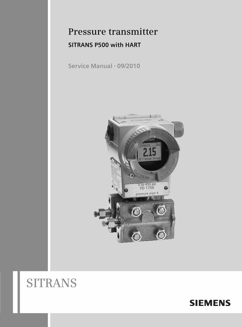
Pressure transmitterSITRANS P500 with HART
Service Manual • 09/2010
www.siemens.com/processautomation
Subject to change without prior noticeA5E02344534-02© Siemens AG 2010
Siemens AGIndustry Automation (IA) Sensors and CommunicationProcess Instrumentation 76181 KARLSRUHEGERMANY
www.siemens.com/processinstrumentation
SITRANSA5E02344534
A5E02344534
! HINWEIS ! PDF-Druckdatei in schwarz/weiß

�SITRANS P500�
___________________
___________________
___________________
___________________
___________________
___________________
___________________
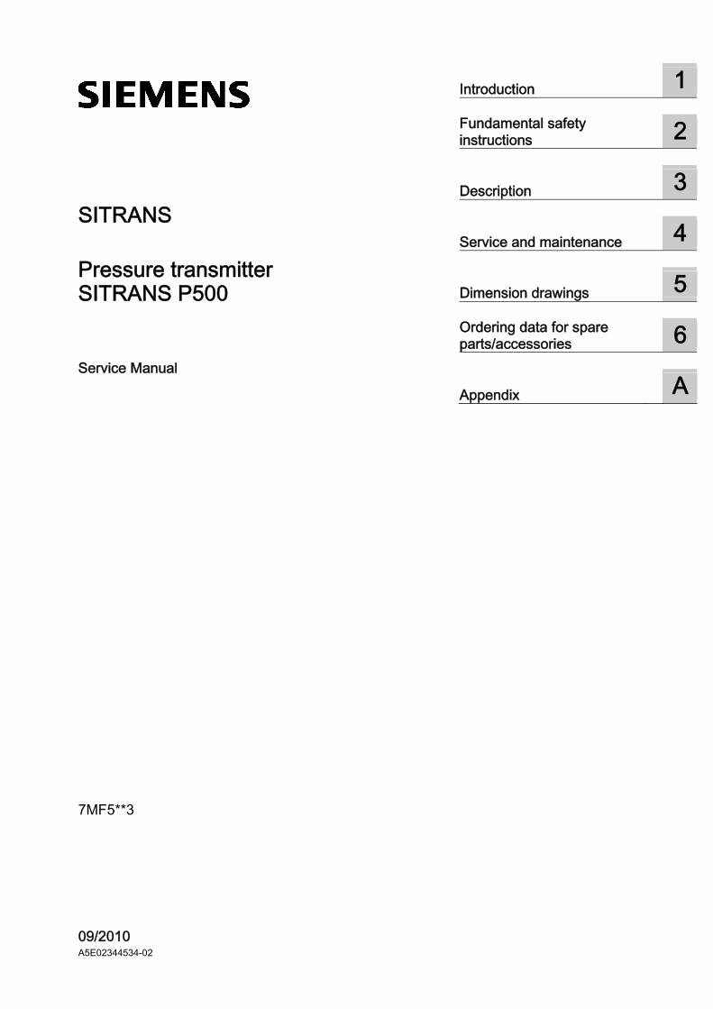
SITRANS
Pressure transmitter SITRANS P500
Service Manual
7MF5**3
09/2010 A5E02344534-02
Introduction 1
Fundamental safety instructions
2
Description 3
Service and maintenance 4
Dimension drawings 5
Ordering data for spare parts/accessories
6
Appendix A
Legal information
Legal information Warning notice system
This manual contains notices you have to observe in order to ensure your personal safety, as well as to prevent damage to property. The notices referring to your personal safety are highlighted in the manual by a safety alert symbol, notices referring only to property damage have no safety alert symbol. These notices shown below are graded according to the degree of danger.
DANGER indicates that death or severe personal injury will result if proper precautions are not taken.
WARNING indicates that death or severe personal injury may result if proper precautions are not taken.
CAUTION with a safety alert symbol, indicates that minor personal injury can result if proper precautions are not taken.
CAUTION without a safety alert symbol, indicates that property damage can result if proper precautions are not taken.
NOTICE indicates that an unintended result or situation can occur if the corresponding information is not taken into account.
If more than one degree of danger is present, the warning notice representing the highest degree of danger will be used. A notice warning of injury to persons with a safety alert symbol may also include a warning relating to property damage.
Qualified Personnel The product/system described in this documentation may be operated only by personnel qualified for the specific task in accordance with the relevant documentation for the specific task, in particular its warning notices and safety instructions. Qualified personnel are those who, based on their training and experience, are capable of identifying risks and avoiding potential hazards when working with these products/systems.
Proper use of Siemens products Note the following:
WARNING Siemens products may only be used for the applications described in the catalog and in the relevant technical documentation. If products and components from other manufacturers are used, these must be recommended or approved by Siemens. Proper transport, storage, installation, assembly, commissioning, operation and maintenance are required to ensure that the products operate safely and without any problems. The permissible ambient conditions must be adhered to. The information in the relevant documentation must be observed.
Trademarks All names identified by ® are registered trademarks of the Siemens AG. The remaining trademarks in this publication may be trademarks whose use by third parties for their own purposes could violate the rights of the owner.
Disclaimer of Liability We have reviewed the contents of this publication to ensure consistency with the hardware and software described. Since variance cannot be precluded entirely, we cannot guarantee full consistency. However, the information in this publication is reviewed regularly and any necessary corrections are included in subsequent editions.
Siemens AG Industry Sector Postfach 48 48 90026 NÜRNBERG GERMANY
order number: A5E02344534 Ⓟ 03/2011
Copyright © Siemens AG 2010. Technical data subject to change
SITRANS P500 Service Manual, 09/2010, A5E02344534-02 3
Table of contents
1 Introduction................................................................................................................................................ 5
1.1 Purpose of this documentation ......................................................................................................5
1.2 History ............................................................................................................................................5
1.3 Notes on warranty..........................................................................................................................5
1.4 Product information........................................................................................................................6
1.5 Conformity with European directives .............................................................................................6
2 Fundamental safety instructions ................................................................................................................ 7
2.1 General information .......................................................................................................................7
2.2 Correct usage.................................................................................................................................7
2.3 Laws and directives .......................................................................................................................7
2.4 Checking the consignment.............................................................................................................8
2.5 Measures .......................................................................................................................................8
2.6 Qualified Personnel......................................................................................................................10
3 Description............................................................................................................................................... 11
3.1 Structure.......................................................................................................................................11
3.2 Structure of the nameplate and approval plate............................................................................12
4 Service and maintenance ........................................................................................................................ 15
4.1 Safety notice for maintenance .....................................................................................................15
4.2 Notes for servicing .......................................................................................................................16
4.3 Notes for servicing of the remote seal .........................................................................................16
4.4 Modular structure .........................................................................................................................17
4.5 Replacing parts ............................................................................................................................18 4.5.1 Exploded view of the device ........................................................................................................18 4.5.2 Replacing the connection board ..................................................................................................19 4.5.3 Replacing the pushbutton module ...............................................................................................21 4.5.4 Replacing the display...................................................................................................................23 4.5.5 Replacing the application electronics ..........................................................................................25 4.5.6 Replacing the measuring cell.......................................................................................................27
4.6 Return procedure .........................................................................................................................29
5 Dimension drawings ................................................................................................................................ 31
5.1 SITRANS P500 for differential pressure, flow rate and absolute pressure from the differential pressure series...........................................................................................................31
5.2 SITRANS P500 for level ..............................................................................................................32
Table of contents
SITRANS P500 4 Service Manual, 09/2010, A5E02344534-02
6 Ordering data for spare parts/accessories ............................................................................................... 35
A Appendix.................................................................................................................................................. 37
A.1 Certificate .................................................................................................................................... 37
A.2 Literature and catalogs................................................................................................................ 37
A.3 Technical support........................................................................................................................ 38
A.4 Repair report for installation of spare parts................................................................................. 39
Glossary .................................................................................................................................................. 43
Index........................................................................................................................................................ 47
SITRANS P500 Service Manual, 09/2010, A5E02344534-02 5
Introduction 11.1 Purpose of this documentation
These instructions contains all information that you will require to replace the connection board, pushbutton module, display, application electronics, and measuring cell of the device.
For information about the safe usage of the device, refer to the detailed version of these instructions and corresponding safety instructions on the electronic data medium.
Read these instructions carefully before you start any service and maintenance work. In order to use the device correctly, first make yourself acquainted with its principle of operation.
Readership of these instructions are service and maintenance technicians.
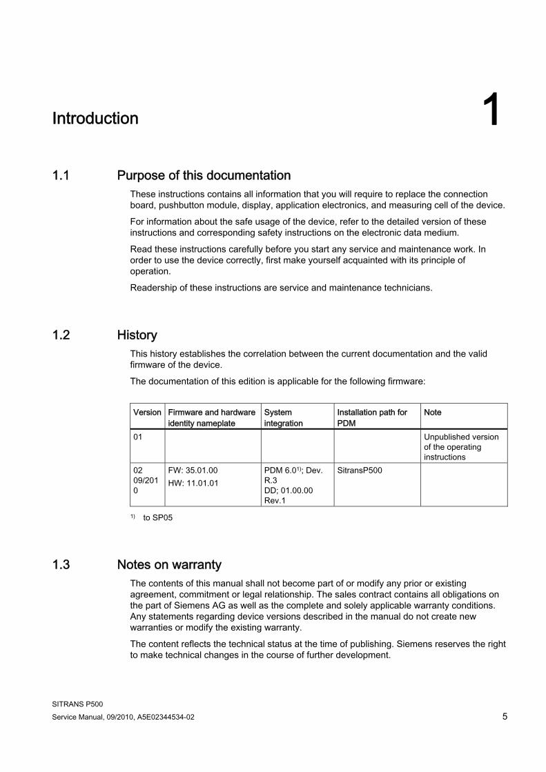
1.2 History This history establishes the correlation between the current documentation and the valid firmware of the device.
The documentation of this edition is applicable for the following firmware:
Version Firmware and hardware
identity nameplate System integration
Installation path for PDM
Note
01 Unpublished version of the operating instructions
02 09/2010
FW: 35.01.00 HW: 11.01.01
PDM 6.01); Dev. R.3 DD; 01.00.00 Rev.1
SitransP500
1) to SP05
1.3 Notes on warranty The contents of this manual shall not become part of or modify any prior or existing agreement, commitment or legal relationship. The sales contract contains all obligations on the part of Siemens AG as well as the complete and solely applicable warranty conditions. Any statements regarding device versions described in the manual do not create new warranties or modify the existing warranty.
The content reflects the technical status at the time of publishing. Siemens reserves the right to make technical changes in the course of further development.
Introduction 1.4 Product information
SITRANS P500 6 Service Manual, 09/2010, A5E02344534-02
1.4 Product information The programming manual is an integral part of the CD, which is either supplied or can be ordered. The programming manual is also available on the Siemens homepage.
On the CD, you will also find the specification sheet with the ordering data, the Software Device Install for SIMATIC PDM for additional installation, and the required software.
See also Product information on SITRANS P in the Internet (http://www.siemens.com/sitransp)
Catalog process instrumentation (http://www.siemens.com/processinstrumentation/catalogs)
1.5 Conformity with European directives The CE mark on the device shows conformity with the provisions of the following European Directives:
EMC 2004/108/EC
Directive of the European Parliament and of the Council on the approximation of the laws of the Member States relating to electromagnetic compatibility and repealing Directive 89/336/EEC.
ATEX 94/9/EC
Directive of the European Parliament and the Council on the approximation of the laws of the Member States concerning equipment and protective systems intended for use in potentially explosive atmospheres.
DGRL 97/23/EC
Directive of the European Parliament and of the Council on the approximation of the laws of the Member States concerning pressure equipment.
The standards applied and their associated versions can be found in the enclosed EC Declaration of Conformity.
SITRANS P500 Service Manual, 09/2010, A5E02344534-02 7
Fundamental safety instructions 22.1 General information
This device left the factory free from safety problems. In order to maintain this status and to ensure safe operation of the device, please observe the safety information and warnings contained in these instructions.
Safety information and symbols must be observed without exception. They must not be removed and must be maintained in legible condition at all times.
2.2 Correct usage The device may only be used for the purposes specified in these instructions.
Insofar as they are not expressly stated in these instructions, all changes to the device are the sole responsibility of the user.
2.3 Laws and directives Disregard of provisions and laws during connection and installation increases the risk of explosions and leaks dues to improper application. To avoid these risks during connection and installation, you should comply with the test certifications, provisions and laws applicable in your country.
For hazardous areas, these are for example:
● IEC 60079-14 (international)
● National Electrical Code (NEC - NFPA 70) (USA)
● Canadian Electrical Code (CEC) (Canada)
● EN 60079-14 (previously VDE 0165, part 1) (EU)
● Working reliability regulation (Germany)
Fundamental safety instructions 2.4 Checking the consignment
SITRANS P500 8 Service Manual, 09/2010, A5E02344534-02
2.4 Checking the consignment 1. Check the packaging and the device for visible damage caused by inappropriate handling
during shipping.
2. Report any claims for damages immediately to the shipping company.
3. Retain the damaged parts for clarification.
4. Check the scope of delivery by comparing the shipping documents with your order for correctness and completeness.
WARNING
Using a damaged or incomplete device
Danger of explosion. Do not start up any damaged or incomplete devices.
2.5 Measures For the sake of safety, the following precautions must be observed:
WARNING "Flameproof enclosure" type of protection
Only open devices with type of protection "Flameproof enclosure" in hazardous areas when the power to the device is turned off, otherwise there is a risk of explosion.
WARNING "Intrinsic safety" protection type
Only connect the device to certified intrinsically safe circuits. These circuits must comply with the technical data indicated on the nameplate or in the certificates and approvals. If the circuits do not comply with the information in the certificates and approvals, the safety required for the approval is longer guaranteed. The "ia" protection level of the device is decreased to the "ib" protection level when intrinsically safe circuits having the "ib" protection level are connected.
WARNING Type of protection "limited energy" nL (zone 2)
Devices with "limited energy" type of protection may be connected and disconnected while in operation. Type of protection "non-sparking" nA (zone 2)
Devices with "non-sparking" protection may only be connected and disconnected when off circuit.
Fundamental safety instructions 2.5 Measures
SITRANS P500 Service Manual, 09/2010, A5E02344534-02 9
WARNING Exposure to aggressive and hazardous process media
The device can be operated both at high pressure and with aggressive and hazardous process media. Therefore, improper use of this device may lead to serious injury and or considerable damage to property. Above all, it must be noted when the device was in use and is to be exchanged.
WARNING Explosion hazard through electrostatic charging
To prevent electrostatic charges building up in a hazardous environment, the key cover must be closed during operation and the screws must be tightened.
Temporary opening of the key cover for purposes of operating the transmitter may be performed at any time, even during operation; after which the screws should be tightened again.
CAUTION Electrostatic Sensitive Devices (ESD)
This device contains electrostatic sensitive devices. Electrostatic sensitive devices may be destroyed by voltages that are undetectable to a human. Voltages of this kind occur as soon as a component or an assembly is touched by a person who is not grounded against static electricity. The damage to a module as a result of overvoltage cannot usually be detected immediately. It may only become apparent after a long period of operation.
Protective measures against discharge of static electricity: Make sure that no power is applied. Before you work with modules, first discharge any static charges from your body, for
example by touching a grounded object. Devices and tools used must be free of static charge. Hold modules only by their edges. Do not touch connector pins or conductor tracks on a module with the ESD notice.
Fundamental safety instructions 2.6 Qualified Personnel
SITRANS P500 10 Service Manual, 09/2010, A5E02344534-02
2.6 Qualified Personnel Qualified personnel are people who are familiar with the installation, mounting, commissioning, and operation of the product. These people have the following qualifications:
● They are authorized, trained or instructed in operating and maintaining devices and systems according to the safety regulations for electrical circuits, high pressures and aggressive as well as hazardous media.
● For explosion-proof devices: They are authorized, trained, or instructed in carrying out work on electrical circuits for hazardous systems.
● They are trained or instructed in maintenance and use of appropriate safety equipment according to the safety regulations.
SITRANS P500 Service Manual, 09/2010, A5E02344534-02 11
Description 33.1 Structure
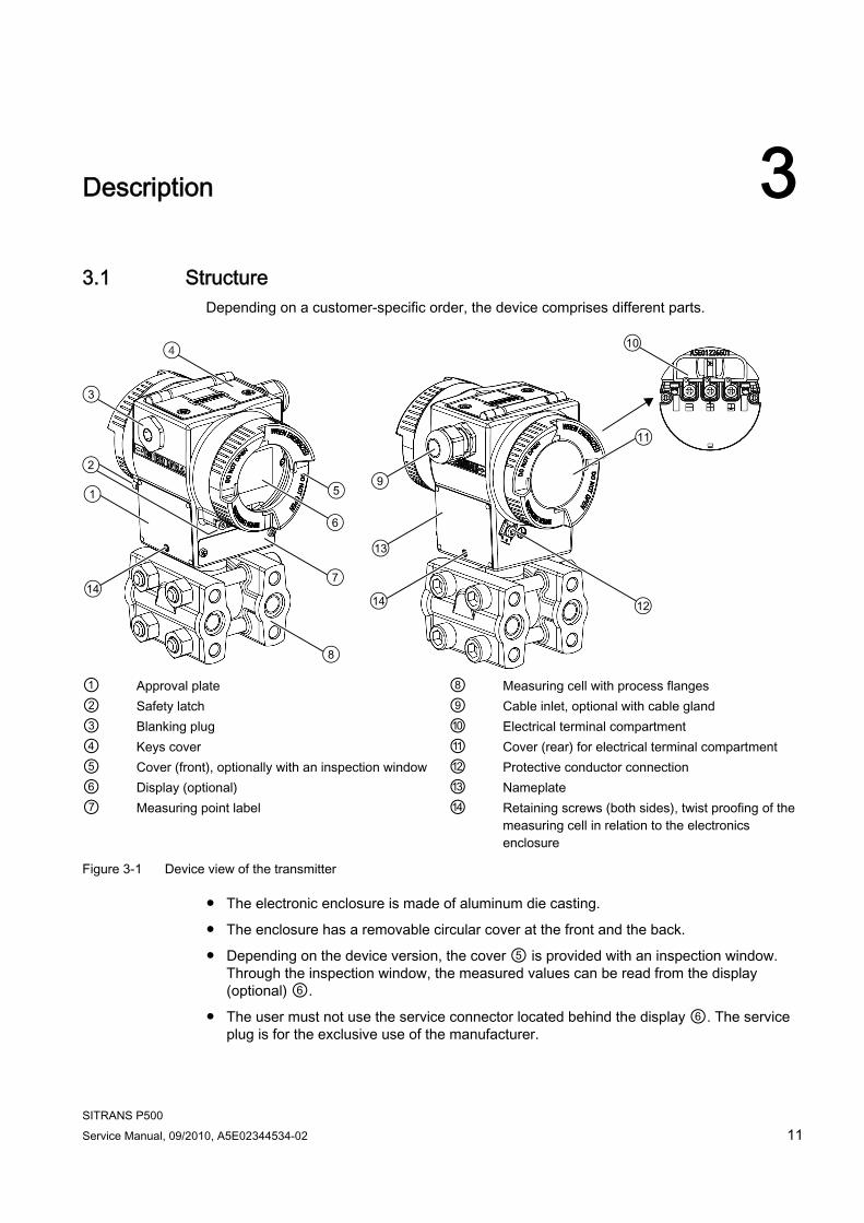
Depending on a customer-specific order, the device comprises different parts.
① Approval plate ⑧ Measuring cell with process flanges ② Safety latch ⑨ Cable inlet, optional with cable gland ③ Blanking plug ⑩ Electrical terminal compartment ④ Keys cover ⑪ Cover (rear) for electrical terminal compartment ⑤ Cover (front), optionally with an inspection window ⑫ Protective conductor connection ⑥ Display (optional) ⑬ Nameplate ⑦ Measuring point label ⑭ Retaining screws (both sides), twist proofing of the
measuring cell in relation to the electronics enclosure
Figure 3-1 Device view of the transmitter
● The electronic enclosure is made of aluminum die casting.
● The enclosure has a removable circular cover at the front and the back.
● Depending on the device version, the cover ⑤ is provided with an inspection window. Through the inspection window, the measured values can be read from the display (optional) ⑥.
● The user must not use the service connector located behind the display ⑥. The service plug is for the exclusive use of the manufacturer.
Description 3.2 Structure of the nameplate and approval plate
SITRANS P500 12 Service Manual, 09/2010, A5E02344534-02
● The cable inlet ⑨ to the electrical terminal compartment on the left or right side can be used selectively. The corresponding unused opening is closed with a blanking plug ③.
● The protective conductor terminal ⑫ is located on the rear of the housing.
● The electrical terminal compartment ⑩ for power supply and shield is accessible when you unscrew the cover ⑪.
● Underneath the electronics housing is the measuring cell with its pressure caps on which the process connections ⑧ are located. The modular structure of the pressure transmitter allows you to replace the measuring cell, application electronics, connection board, pushbutton module, and the optional display when required.
● On the upper face of the enclosure you can see crosshead screws which secure the cover ④, under which the 3 keys for local operation are located.
3.2 Structure of the nameplate and approval plate
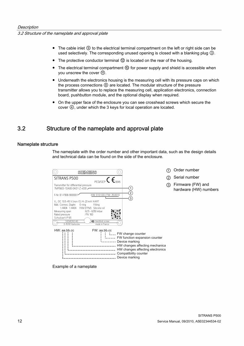
Nameplate structure The nameplate with the order number and other important data, such as the design details and technical data can be found on the side of the enclosure.
① Order number
② Serial number
twistlock screwSchutzart IP 65Rated pressure : PN 160Measuring span : 62.5 - 6250 mbar
1. 4404 1. 4404 FKM (FPM) Silicone oilMat.: Connec. Diaphr. O-ring FillingV : DC 10.5-45 V (non IS) 4-20 mA HARTH
F.-Nr. B1-F908-9000001
7MF5603-1DA00-0AD1-Z +E00Transmitter for differential pressure
0045PED/SEP
HW: 01.01.00 / FW: 35.00.10
made in FranceD-76181 KarlsruheSIEMENS AG
SITRANS P500
Example of a nameplate
③ Firmware (FW) and hardware (HW) numbers
Description 3.2 Structure of the nameplate and approval plate
SITRANS P500 Service Manual, 09/2010, A5E02344534-02 13
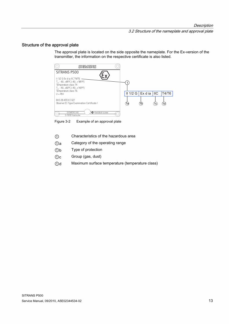
Structure of the approval plate The approval plate is located on the side opposite the nameplate. For the Ex-version of the transmitter, the information on the respective certificate is also listed.
twistlock screw
II 1/2 G Ex d ia IIC T4/T6
Temperature class T4T : -40...+85°C (-40...+185°F)a
U = 45V
Observe EC-Type Examination Certificate !BVS 09 ATEX E 027
T : -40...+60°C (-40...+140°F)aTemperature class T6
D-76181 KarlsruheSIEMENS AG
SITRANS P500
Figure 3-2 Example of an approval plate
① Characteristics of the hazardous area
①a Category of the operating range
①b Type of protection
①c Group (gas, dust)
①d Maximum surface temperature (temperature class)

Description 3.2 Structure of the nameplate and approval plate
SITRANS P500 14 Service Manual, 09/2010, A5E02344534-02
SITRANS P500 Service Manual, 09/2010, A5E02344534-02 15
Service and maintenance 44.1 Safety notice for maintenance
For all devices
WARNING This device is designed to operate with high pressure and / or hazardous media. For this reason, repair and maintenance work performed on this device with connected supply lines can result in the leakage of hazardous substances from these lines.
Therefore you must ensure that substances cannot leak prior to opening or dismantling the device, e.g. block the line or separate the line from the device.
WARNING If you are unable to eliminate faults, place the device out of service and protect it against inadvertent commissioning.
CAUTION If the membrane of the pressure connection is cleaned with pointed or hard objects, you can destroy the membrane.
Therefore, do not use pointed or hard objects to clean the membrane.
NOTICE Depending on the use of the device and certain empirical values, determine a maintenance interval for the tests to be carried out repeatedly.
The maintenance interval is also influenced by the corrosion resistance depending on the site of use.
General explosion protection
WARNING An explosion hazard exists when the device is repaired or serviced in explosive atmospheres.
Before opening the device, ensure that the surrounding atmosphere is not potentially explosive.
Service and maintenance 4.2 Notes for servicing
SITRANS P500 16 Service Manual, 09/2010, A5E02344534-02
WARNING So as to ensure the safety of the explosion protection, the device may be repaired only by repair shops authorized by the manufacturer.
4.2 Notes for servicing
Note Checking the gaskets
At regular intervals, check that the enclosure seals of the pressure transmitter satisfy IP66 / IP68. Grease or replace the gaskets if required.
4.3 Notes for servicing of the remote seal The remote seal measuring system usually does not need servicing.
If the mediums are contaminated, viscous or crystallized, it could be necessary to clean the diaphragm from time to time. Use only a soft brush and a suitable solvent to remove the deposits from the diaphragm. Do not use corrosive cleaning agents. Prevent the diaphragm from getting damaged due to sharp-edged tools.
Service and maintenance 4.4 Modular structure
SITRANS P500 Service Manual, 09/2010, A5E02344534-02 17
4.4 Modular structure
Safety note
NOTICE Improper replacement of components
The structure of the device is modular. This makes it easy to replace various components with original spare parts. When replacing an item, please adhere to all installation and safety notices which are
attached to the replacement part. in particular for devices which are used in areas that present an explosion hazard.
Related The two individual components of measuring cell and application electronics both contain a non-volatile memory (EEPROM).
Measuring cell data (e.g.: The measuring range, measuring cell material (oil filling) and application-specific data of the application electronics (such as: down-scaling, additional electrical damping) are stored in the EEPROM in the measuring cell. When the measuring cell is replaced, the application-specific data are lost. When the application electronics are replaced, no data are lost.
Before replacing the measuring cell, you have the option of saving the application-specific data and then reloading it after the replacement. For this you should use an input device which supports the HART protocol. (e.g. HART Communicator, PC with HART modem and HART software or PC with HART modem and PDM software). If the application-specific data was not saved before the measuring cell was replaced, following the replacement the factory settings will be used.
Further technical developments enable the implementation of extended functions in the firmware of the measuring cell or the application electronics. Further technical developments are indicated by changes to the firmware versions (FW). The firmware version does not affect the facility to replace modules. The functional scope is however restricted to the functionality of the components that are fitted.
If for technical reasons the combination of certain firmware versions of the measuring cell and application electronics is not compatible, the device detects this and switches to "fault current" mode. This information is provided via the HART interface.
Service and maintenance 4.5 Replacing parts
SITRANS P500 18 Service Manual, 09/2010, A5E02344534-02
4.5 Replacing parts
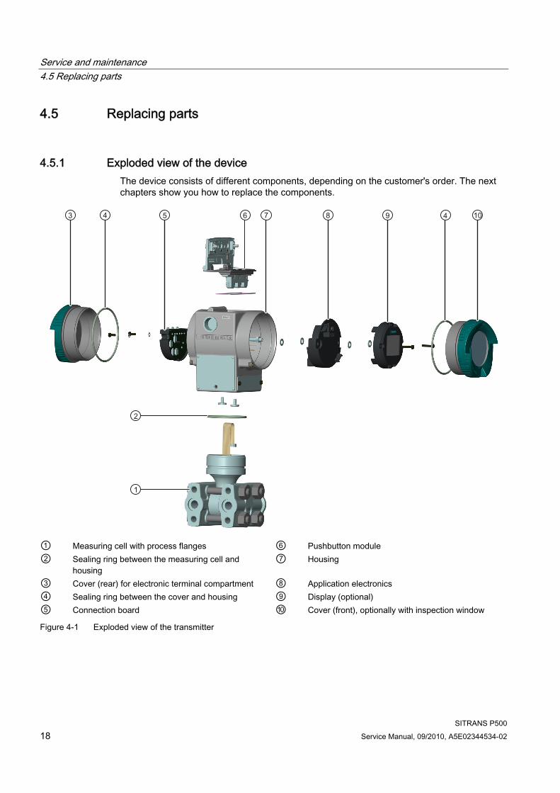
4.5.1 Exploded view of the device The device consists of different components, depending on the customer's order. The next chapters show you how to replace the components.
① Measuring cell with process flanges ⑥ Pushbutton module ② Sealing ring between the measuring cell and
housing ⑦ Housing
③ Cover (rear) for electronic terminal compartment ⑧ Application electronics ④ Sealing ring between the cover and housing ⑨ Display (optional) ⑤ Connection board ⑩ Cover (front), optionally with inspection window
Figure 4-1 Exploded view of the transmitter
Service and maintenance 4.5 Replacing parts
SITRANS P500 Service Manual, 09/2010, A5E02344534-02 19
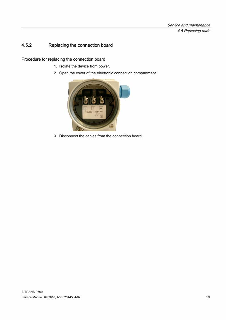
4.5.2 Replacing the connection board
Procedure for replacing the connection board 1. Isolate the device from power.
2. Open the cover of the electronic connection compartment.
3. Disconnect the cables from the connection board.
Service and maintenance 4.5 Replacing parts
SITRANS P500 20 Service Manual, 09/2010, A5E02344534-02
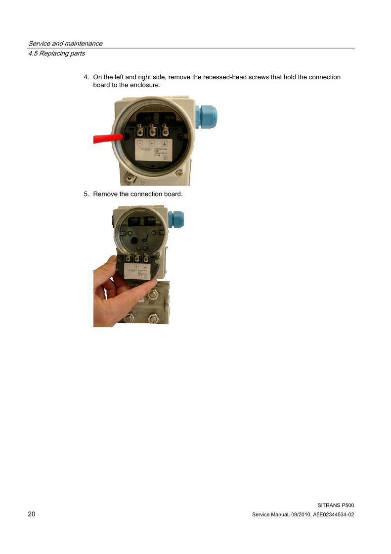
4. On the left and right side, remove the recessed-head screws that hold the connection board to the enclosure.
5. Remove the connection board.
Service and maintenance 4.5 Replacing parts
SITRANS P500 Service Manual, 09/2010, A5E02344534-02 21
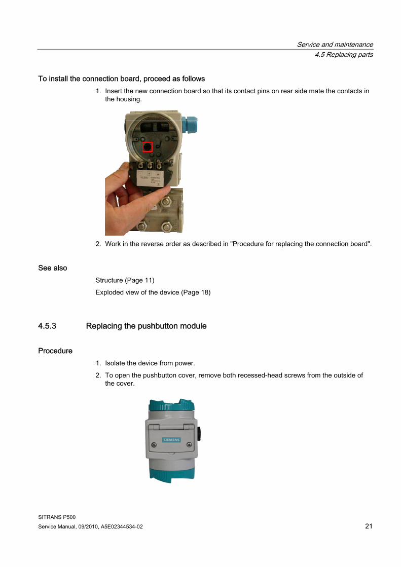
To install the connection board, proceed as follows 1. Insert the new connection board so that its contact pins on rear side mate the contacts in
the housing.
2. Work in the reverse order as described in "Procedure for replacing the connection board".
See also Structure (Page 11)
Exploded view of the device (Page 18)
4.5.3 Replacing the pushbutton module
Procedure 1. Isolate the device from power.
2. To open the pushbutton cover, remove both recessed-head screws from the outside of the cover.
Service and maintenance 4.5 Replacing parts
SITRANS P500 22 Service Manual, 09/2010, A5E02344534-02
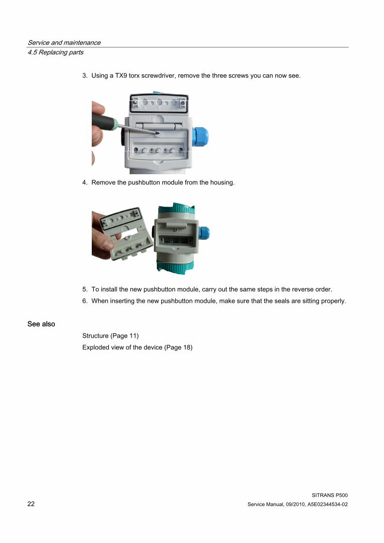
3. Using a TX9 torx screwdriver, remove the three screws you can now see.
4. Remove the pushbutton module from the housing.
5. To install the new pushbutton module, carry out the same steps in the reverse order.
6. When inserting the new pushbutton module, make sure that the seals are sitting properly.
See also Structure (Page 11)
Exploded view of the device (Page 18)
Service and maintenance 4.5 Replacing parts
SITRANS P500 Service Manual, 09/2010, A5E02344534-02 23
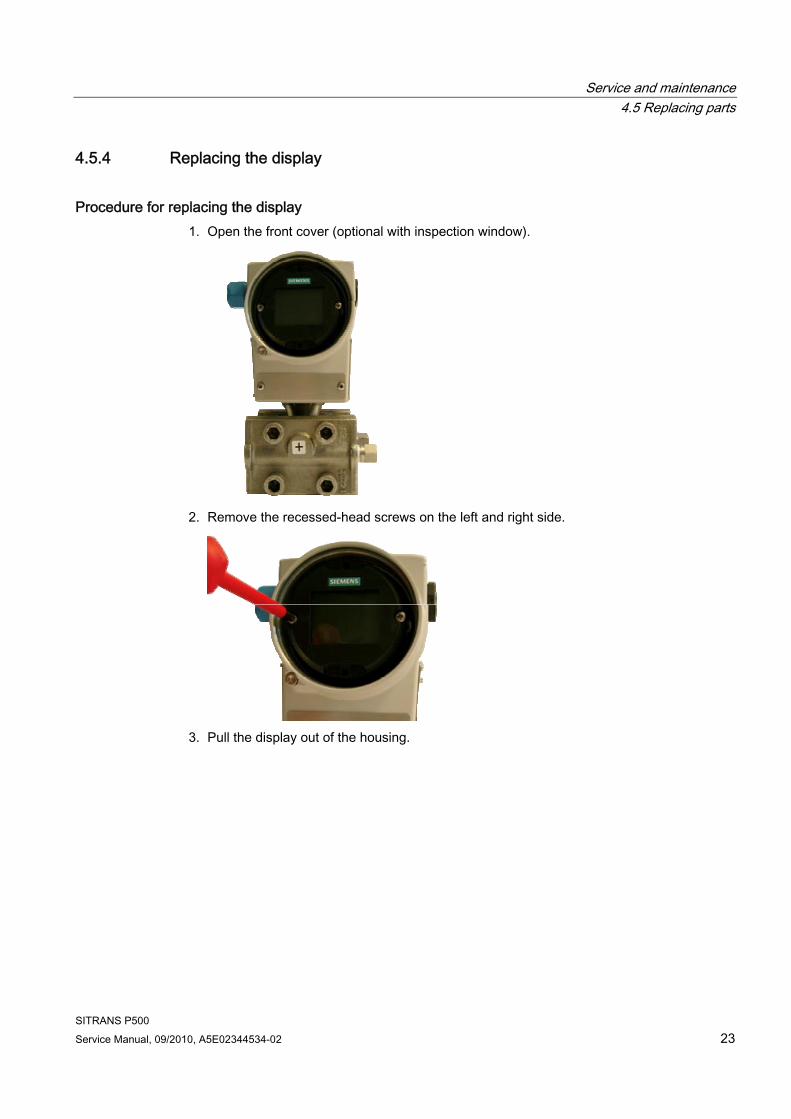
4.5.4 Replacing the display
Procedure for replacing the display 1. Open the front cover (optional with inspection window).
2. Remove the recessed-head screws on the left and right side.
3. Pull the display out of the housing.
Service and maintenance 4.5 Replacing parts
SITRANS P500 24 Service Manual, 09/2010, A5E02344534-02
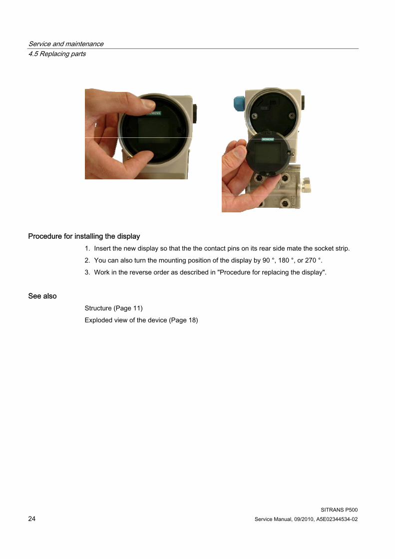
Procedure for installing the display 1. Insert the new display so that the the contact pins on its rear side mate the socket strip.
2. You can also turn the mounting position of the display by 90 °, 180 °, or 270 °.
3. Work in the reverse order as described in "Procedure for replacing the display".
See also Structure (Page 11)
Exploded view of the device (Page 18)
Service and maintenance 4.5 Replacing parts
SITRANS P500 Service Manual, 09/2010, A5E02344534-02 25
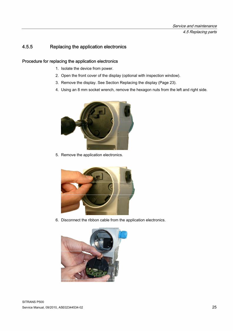
4.5.5 Replacing the application electronics
Procedure for replacing the application electronics 1. Isolate the device from power.
2. Open the front cover of the display (optional with inspection window).
3. Remove the display. See Section Replacing the display (Page 23).
4. Using an 8 mm socket wrench, remove the hexagon nuts from the left and right side.
5. Remove the application electronics.
6. Disconnect the ribbon cable from the application electronics.
Service and maintenance 4.5 Replacing parts
SITRANS P500 26 Service Manual, 09/2010, A5E02344534-02
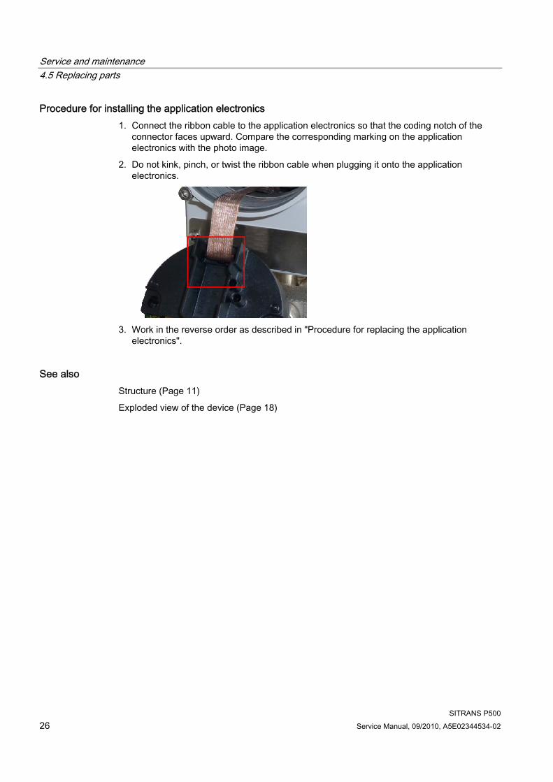
Procedure for installing the application electronics 1. Connect the ribbon cable to the application electronics so that the coding notch of the
connector faces upward. Compare the corresponding marking on the application electronics with the photo image.
2. Do not kink, pinch, or twist the ribbon cable when plugging it onto the application electronics.
3. Work in the reverse order as described in "Procedure for replacing the application
electronics".
See also Structure (Page 11)
Exploded view of the device (Page 18)
Service and maintenance 4.5 Replacing parts
SITRANS P500 Service Manual, 09/2010, A5E02344534-02 27
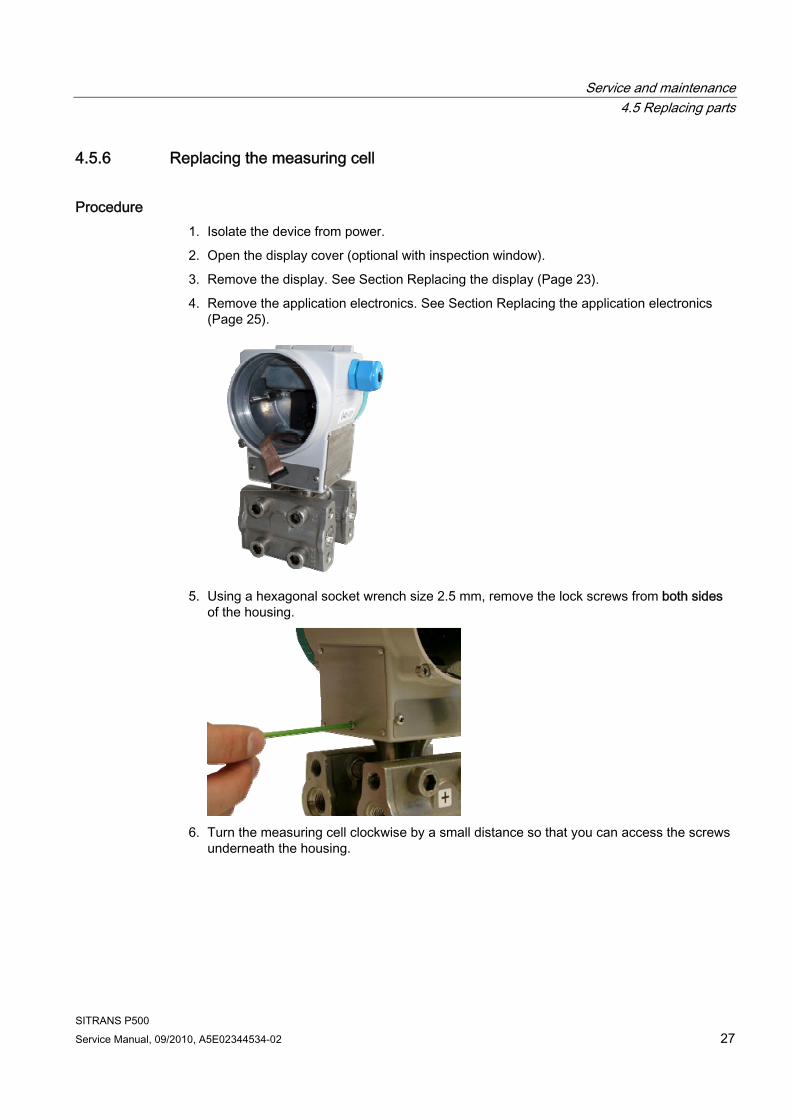
4.5.6 Replacing the measuring cell
Procedure 1. Isolate the device from power.
2. Open the display cover (optional with inspection window).
3. Remove the display. See Section Replacing the display (Page 23).
4. Remove the application electronics. See Section Replacing the application electronics (Page 25).
5. Using a hexagonal socket wrench size 2.5 mm, remove the lock screws from both sides
of the housing.
6. Turn the measuring cell clockwise by a small distance so that you can access the screws
underneath the housing.
Service and maintenance 4.5 Replacing parts
SITRANS P500 28 Service Manual, 09/2010, A5E02344534-02
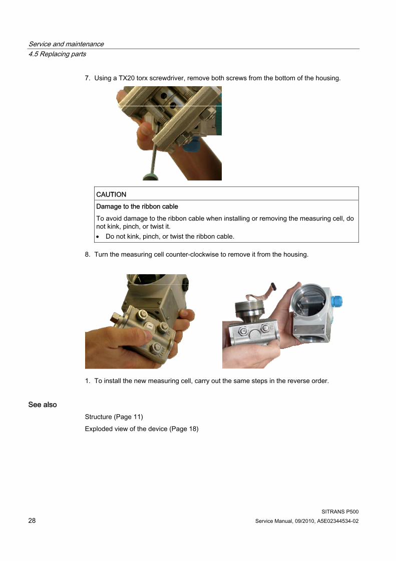
7. Using a TX20 torx screwdriver, remove both screws from the bottom of the housing.
CAUTION
Damage to the ribbon cable
To avoid damage to the ribbon cable when installing or removing the measuring cell, do not kink, pinch, or twist it. Do not kink, pinch, or twist the ribbon cable.
8. Turn the measuring cell counter-clockwise to remove it from the housing.
1. To install the new measuring cell, carry out the same steps in the reverse order.
See also Structure (Page 11)
Exploded view of the device (Page 18)
Service and maintenance 4.6 Return procedure
SITRANS P500 Service Manual, 09/2010, A5E02344534-02 29
4.6 Return procedure Enclose the bill of lading, return document and decontamination certificate in a clear plastic pouch and attach it firmly to the outside of the packaging.
Required forms ● Delivery note
● Return goods delivery note (http://www.siemens.com/processinstrumentation/returngoodsnote)
with the following information:
– Product (item description)
– Number of returned devices/replacement parts
– Reason for returning the item(s)
● Decontamination declaration (http://www.siemens.com/sc/declarationofdecontamination)
With this declaration you warrant "that the device/replacement part has been carefully cleaned and is free of residues. The device/replacement part does not pose a hazard for humans and the environment."
If the returned device/replacement part has come into contact with poisonous, corrosive, flammable or water-contaminating substances, you must thoroughly clean and decontaminate the device/replacement part before returning it in order to ensure that all hollow areas are free from hazardous substances. Check the item after it has been cleaned.
Any devices/replacement parts returned without a decontamination declaration will be cleaned at your expense before further processing.
The forms can be found on the Internet as well as in the documentation which comes with the device.

Service and maintenance 4.6 Return procedure
SITRANS P500 30 Service Manual, 09/2010, A5E02344534-02
SITRANS P500 Service Manual, 09/2010, A5E02344534-02 31
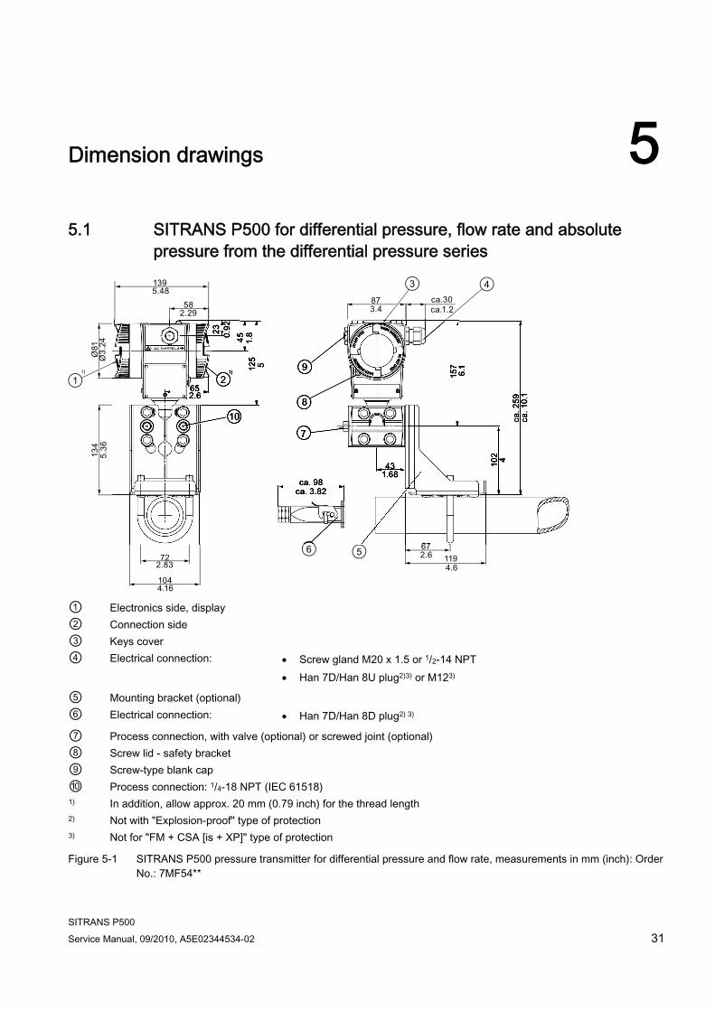
Dimension drawings 55.1 SITRANS P500 for differential pressure, flow rate and absolute
pressure from the differential pressure series
① Electronics side, display ② Connection side ③ Keys cover ④ Electrical connection: Screw gland M20 x 1.5 or 1/2-14 NPT
Han 7D/Han 8U plug2)3) or M123)
⑤ Mounting bracket (optional) ⑥ Electrical connection: Han 7D/Han 8D plug2) 3)
⑦ Process connection, with valve (optional) or screwed joint (optional) ⑧ Screw lid - safety bracket ⑨ Screw-type blank cap ⑩ Process connection: 1/4-18 NPT (IEC 61518) 1) In addition, allow approx. 20 mm (0.79 inch) for the thread length 2) Not with "Explosion-proof" type of protection 3) Not for "FM + CSA [is + XP]" type of protection
Figure 5-1 SITRANS P500 pressure transmitter for differential pressure and flow rate, measurements in mm (inch): Order No.: 7MF54**
Dimension drawings 5.2 SITRANS P500 for level
SITRANS P500 32 Service Manual, 09/2010, A5E02344534-02
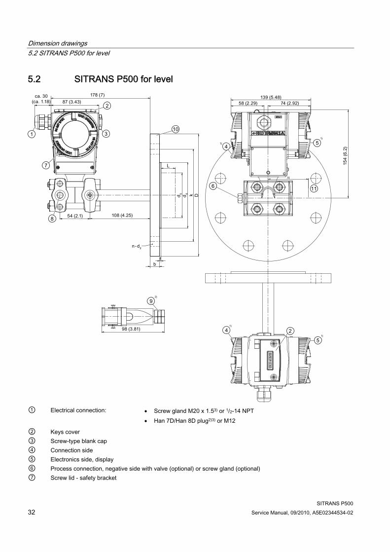
5.2 SITRANS P500 for level
① Electrical connection: Screw gland M20 x 1.53) or 1/2-14 NPT
Han 7D/Han 8D plug2)3) or M12
② Keys cover ③ Screw-type blank cap ④ Connection side ⑤ Electronics side, display ⑥ Process connection, negative side with valve (optional) or screw gland (optional) ⑦ Screw lid - safety bracket
Dimension drawings 5.2 SITRANS P500 for level
SITRANS P500 Service Manual, 09/2010, A5E02344534-02 33
⑧ Process connection: Negative side 1/4-18 NPT (IEC 61518) ⑨ Electrical connection: Han 7D/Han 8D plug2) 3)
⑩ Mounting flange as per EN1092-1 or ASME B16.5 ⑪ Free space for turning housing 1) In addition, allow approx. 20 mm (0.79 inch) for the thread length 2) Not with "Explosion-proof" type of protection 3) Not for "FM + CSA [is + XP]" type of protection
Figure 5-2 SITRANS P500 pressure transmitter for level, including mounting flange, measurements in mm (inch): Order No.: 7MF56**

Dimension drawings 5.2 SITRANS P500 for level
SITRANS P500 34 Service Manual, 09/2010, A5E02344534-02
SITRANS P500 Service Manual, 09/2010, A5E02344534-02 35
Ordering data for spare parts/accessories 6
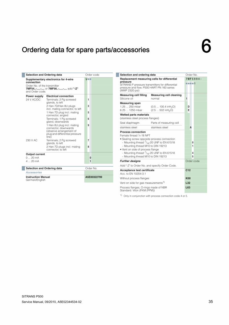
Selection and Ordering data Order code
Supplementary electronics for 4-wire connection
V
Order No. of the transmitter7MF54..-.....-.... or 7MF56..-.....-.... add "-Z" and Order code.
Power supply Electrical connection24 V AC/DC Terminals; 2 Pg screwed
glands, to left1
2 Han 7D/Han 8U plugs incl. mating connector, to left
3
1 Han 7D plug incl. mating connector, angled
5
Terminals; 1 Pg screwed gland, downwards
6
1 Han 8U plug incl. mating connector, downwards (observe arrangement of plug and differential pressure line)
9
230 V AC Terminals; 2 Pg screwed glands, to left
7
2 Han 7D plugs incl. mating connector, to left
8
Output current0 ... 20 mA 04 ... 20 mA 1
Selection and Ordering data Order No.
Accessories
Instruction ManualGerman/English
A5E00322799
Selection and ordering data Order No.
Replacement measuring cells for differential pressure SITRANS P pressure transmitters for differential pressure and flow, P500 HART PN 160 series (MWP 2320 psi)
7 M F 5 9 9 4 -
1
Measuring cell filling Measuring cell cleaningSilicone oil normal 1
Measuring span1.25 ... 250 mbar (0.5 ... 100.4 inH2O) D6.25 ... 1250 mbar (2.5 ... 502 inH2O) E
Wetted parts materials(stainless steel process flanges)
Seal diaphragm Parts of measuring cell
stainless steel stainless steel A
Process connectionFemale thread ¼-18 NPT• Sealing screw opposite process connection
- Mounting thread 7/16-20 UNF to EN 61518 0- Mounting thread M10 to DIN 19213 1
• Vent on side of process flange - Mounting thread 7/16-20 UNF to EN 61518 4- Mounting thread M10 to DIN 19213 5
Further designs Order code
Add "-Z" to Order No. and specify Order Code.
Acceptance test certificate C12Acc. to EN 10204-3.1
Without process flanges K00
Vent on side for gas measurements1)
1) Only in conjunction with process connection code 4 or 5.
L32
Process flanges, O-rings made of NBRStandard: Viton (FKM (FPM))
L63
Ordering data for spare parts/accessories
SITRANS P500 36 Service Manual, 09/2010, A5E02344534-02
Selection and Ordering data
Selection and Ordering data
1) You can download these operating instructions free-of-charge from our Internet site at www.siemens.de/sitransp.
D) Subject to export regulations AL: 9I999, ECCN: N.
F) Subject to export regulations AL: N, ECCN: EAR99H.
Available ex stock.
For power supply units, see catalog FI01 "Supplementary Com-pontents".
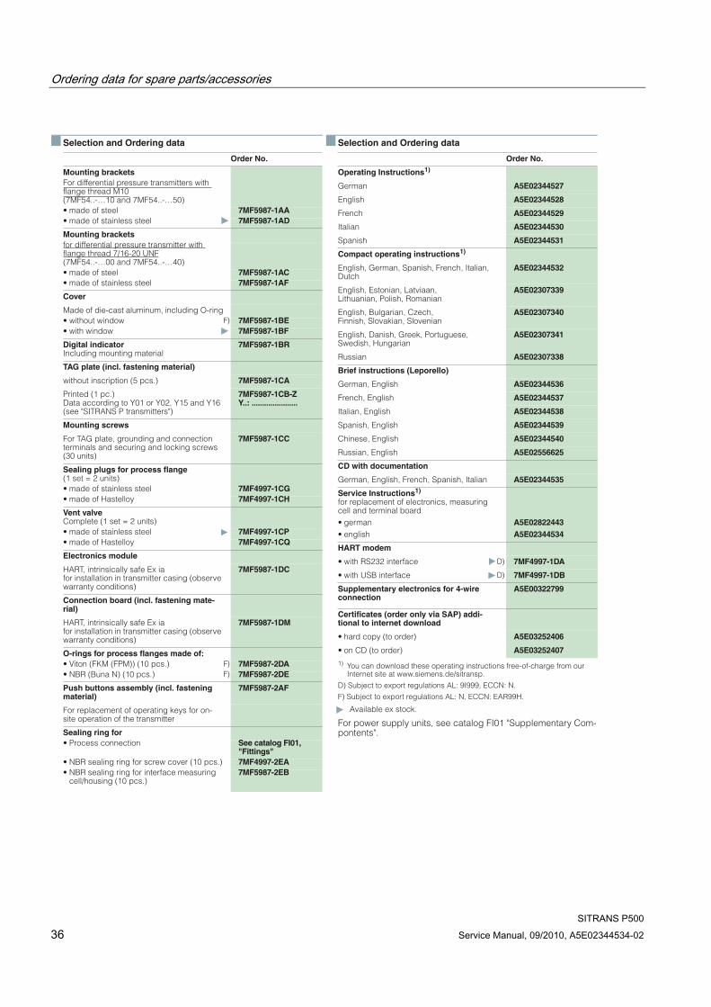
Order No.
Mounting bracketsFor differential pressure transmitters with flange thread M10(7MF54..-…10 and 7MF54..-…50)• made of steel 7MF5987-1AA• made of stainless steel 7MF5987-1AD
Mounting bracketsfor differential pressure transmitter with flange thread 7/16-20 UNF(7MF54..-…00 and 7MF54..-…40)• made of steel 7MF5987-1AC• made of stainless steel 7MF5987-1AF
Cover
Made of die-cast aluminum, including O-ring• without window F) 7MF5987-1BE• with window 7MF5987-1BF
Digital indicatorIncluding mounting material
7MF5987-1BR
TAG plate (incl. fastening material)
without inscription (5 pcs.) 7MF5987-1CA
Printed (1 pc.)Data according to Y01 or Y02, Y15 and Y16 (see "SITRANS P transmitters")
7MF5987-1CB-ZY..: ......................
Mounting screws
For TAG plate, grounding and connection terminals and securing and locking screws (30 units)
7MF5987-1CC
Sealing plugs for process flange(1 set = 2 units)• made of stainless steel 7MF4997-1CG• made of Hastelloy 7MF4997-1CH
Vent valve Complete (1 set = 2 units)• made of stainless steel 7MF4997-1CP• made of Hastelloy 7MF4997-1CQ
Electronics module
HART, intrinsically safe Ex iafor installation in transmitter casing (observe warranty conditions)
7MF5987-1DC
Connection board (incl. fastening mate-rial)
HART, intrinsically safe Ex iafor installation in transmitter casing (observe warranty conditions)
7MF5987-1DM
O-rings for process flanges made of:• Viton (FKM (FPM)) (10 pcs.) F) 7MF5987-2DA• NBR (Buna N) (10 pcs.) F) 7MF5987-2DE
Push buttons assembly (incl. fastening material)
7MF5987-2AF
For replacement of operating keys for on-site operation of the transmitter
Sealing ring for • Process connection See catalog FI01,
"Fittings"• NBR sealing ring for screw cover (10 pcs.) 7MF4997-2EA• NBR sealing ring for interface measuring
cell/housing (10 pcs.)7MF5987-2EB
Order No.
Operating Instructions1)
German A5E02344527
English A5E02344528
French A5E02344529
Italian A5E02344530
Spanish A5E02344531
Compact operating instructions1)
English, German, Spanish, French, Italian, Dutch
A5E02344532
English, Estonian, Latviaan, Lithuanian, Polish, Romanian
A5E02307339
English, Bulgarian, Czech, Finnish, Slovakian, Slovenian
A5E02307340
English, Danish, Greek, Portuguese, Swedish, Hungarian
A5E02307341
Russian A5E02307338
Brief instructions (Leporello)
German, English A5E02344536
French, English A5E02344537
Italian, English A5E02344538
Spanish, English A5E02344539
Chinese, English A5E02344540
Russian, English A5E02556625
CD with documentation
German, English, French, Spanish, Italian A5E02344535
Service Instructions1)
for replacement of electronics, measuring cell and terminal board• german• english
A5E02822443A5E02344534
HART modem
• with RS232 interface D) 7MF4997-1DA
• with USB interface D) 7MF4997-1DB
Supplementary electronics for 4-wire connection
A5E00322799
Certificates (order only via SAP) addi-tional to internet download
• hard copy (to order) A5E03252406
• on CD (to order) A5E03252407
SITRANS P500 Service Manual, 09/2010, A5E02344534-02 37
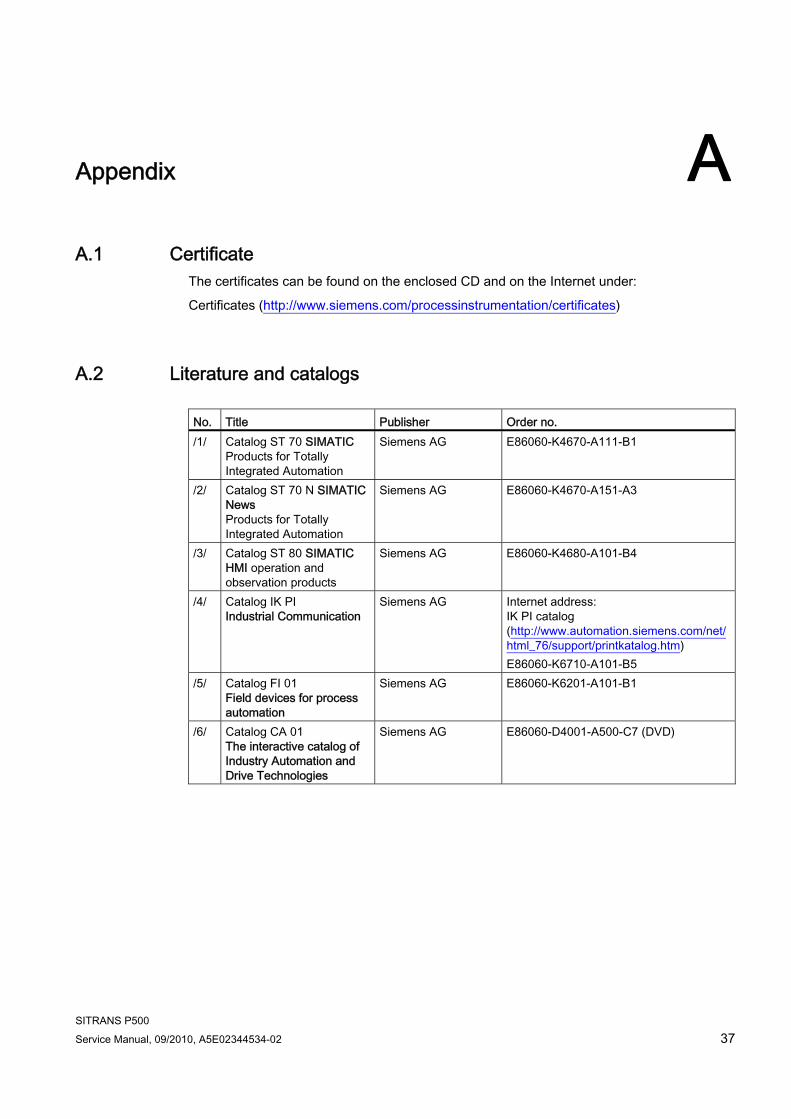
Appendix AA.1 Certificate
The certificates can be found on the enclosed CD and on the Internet under:
Certificates (http://www.siemens.com/processinstrumentation/certificates)
A.2 Literature and catalogs No. Title Publisher Order no. /1/ Catalog ST 70 SIMATIC
Products for Totally Integrated Automation
Siemens AG E86060-K4670-A111-B1
/2/ Catalog ST 70 N SIMATIC News Products for Totally Integrated Automation
Siemens AG E86060-K4670-A151-A3
/3/ Catalog ST 80 SIMATIC HMI operation and observation products
Siemens AG E86060-K4680-A101-B4
/4/ Catalog IK PI Industrial Communication
Siemens AG Internet address: IK PI catalog (http://www.automation.siemens.com/net/html_76/support/printkatalog.htm) E86060-K6710-A101-B5
/5/ Catalog FI 01 Field devices for process automation
Siemens AG E86060-K6201-A101-B1
/6/ Catalog CA 01 The interactive catalog of Industry Automation and Drive Technologies
Siemens AG E86060-D4001-A500-C7 (DVD)
Appendix A.3 Technical support
SITRANS P500 38 Service Manual, 09/2010, A5E02344534-02
A.3 Technical support
Technical Support You can contact Technical Support for all IA and DT products:
● Via the Internet using the Support Request: Support request (http://www.siemens.com/automation/support-request)
● E-mail (mailto:[email protected])
● Phone: +49 (0) 911 895 7 222
● Fax: +49 (0) 911 895 7 223
Further information about our technical support is available in the Internet at Technical Support (http://www.siemens.com/automation/csi/service)
Service & Support on the Internet In addition to our documentation, we offer a comprehensive knowledge base online on the Internet at:
Services & Support (http://www.siemens.com/automation/service&support)
There you will find:
● The latest product information, FAQs, downloads, tips and tricks.
● Our newsletter, providing you with the latest information about your products.
● A Knowledge Manager to find the right documents for you.
● Our bulletin board, where users and specialists share their knowledge worldwide.
● You can find your local contact partner for Industry Automation and Drives Technologies in our partner database.
● Information about field service, repairs, spare parts and lots more under "Services."
Additional Support Please contact your local Siemens representative and offices if you have any questions about the products described in this manual and do not find the right answers.
Find your contact partner at:
Partner (http://www.automation.siemens.com/partner)
A signpost to the documentation of the various products and systems is available at:
Instructions and Manuals (http://www.siemens.com/processinstrumentation/documentation)
See also Product information on SITRANS P in the Internet (http://www.siemens.com/sitransp)
Catalog process instrumentation (http://www.siemens.com/processinstrumentation/catalogs)
Appendix A.4 Repair report for installation of spare parts
SITRANS P500 Service Manual, 09/2010, A5E02344534-02 39
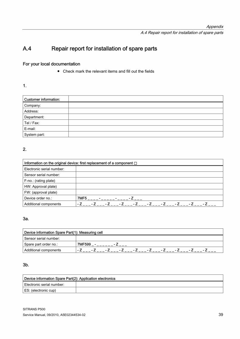
A.4 Repair report for installation of spare parts
For your local documentation ● Check mark the relevant items and fill out the fields
1. Customer information: Company: Address: Department: Tel / Fax: E-mail: System part:
2. Information on the original device: first replacement of a component ⃞ Electronic serial number: Sensor serial number: F-no.: (rating plate) HW: Approval plate) FW: (approval plate) Device order no.: 7MF5 _ _ _ _ - _ _ _ _ _ - _ _ _ _ - Z _ _ _ Additional components - Z _ _ _ - Z _ _ _ - Z _ _ _ - Z _ _ _ - Z _ _ _ - Z _ _ _ - Z _ _ _ - Z _ _ _ - Z _ _ _ - Z _ _ _
3a. Device information Spare Part(1): Measuring cell Sensor serial number: Spare part order no.: 7MF599 _ - _ _ _ _ _ _ - Z _ _ _ Additional components - Z _ _ _ - Z _ _ _ - Z _ _ _ - Z _ _ _ - Z _ _ _ - Z _ _ _ - Z _ _ _ - Z _ _ _ - Z _ _ _ - Z _ _ _
3b. Device information Spare Part(2): Application electronics Electronic serial number: ES: (electronic cup)
Appendix A.4 Repair report for installation of spare parts
SITRANS P500 40 Service Manual, 09/2010, A5E02344534-02
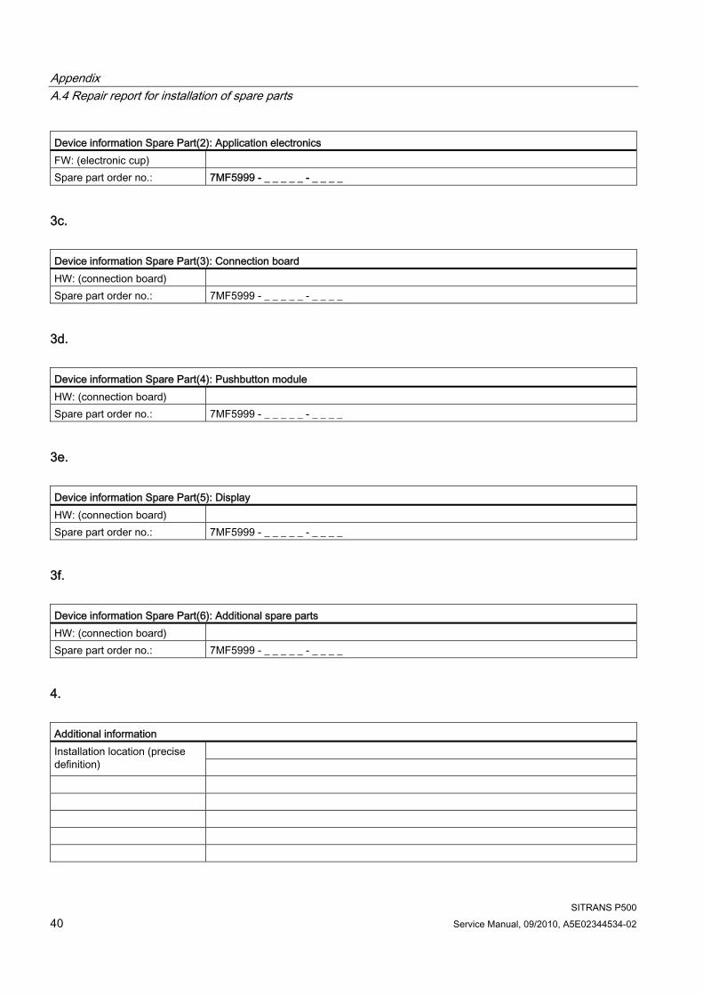
Device information Spare Part(2): Application electronics FW: (electronic cup) Spare part order no.: 7MF5999 - _ _ _ _ _ - _ _ _ _
3c. Device information Spare Part(3): Connection board HW: (connection board) Spare part order no.: 7MF5999 - _ _ _ _ _ - _ _ _ _
3d. Device information Spare Part(4): Pushbutton module HW: (connection board) Spare part order no.: 7MF5999 - _ _ _ _ _ - _ _ _ _
3e. Device information Spare Part(5): Display HW: (connection board) Spare part order no.: 7MF5999 - _ _ _ _ _ - _ _ _ _
3f. Device information Spare Part(6): Additional spare parts HW: (connection board) Spare part order no.: 7MF5999 - _ _ _ _ _ - _ _ _ _
4. Additional information
Installation location (precise definition)
Appendix A.4 Repair report for installation of spare parts
SITRANS P500 Service Manual, 09/2010, A5E02344534-02 41
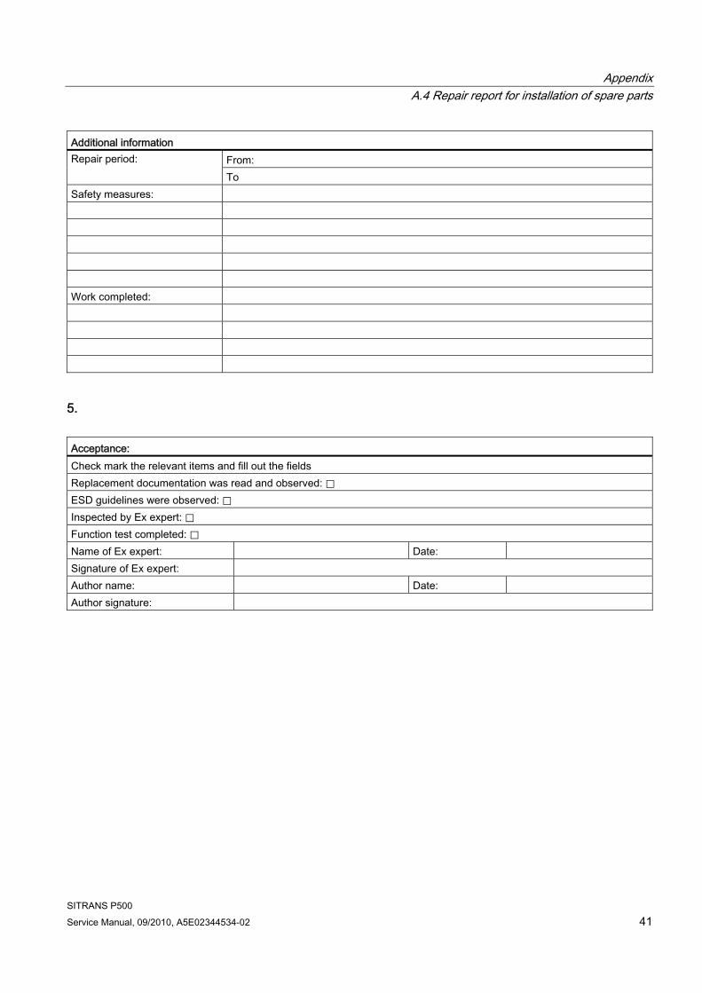
Additional information From: Repair period: To
Safety measures: Work completed:
5. Acceptance: Check mark the relevant items and fill out the fields Replacement documentation was read and observed: ⃞ ESD guidelines were observed: ⃞ Inspected by Ex expert: ⃞ Function test completed: ⃞ Name of Ex expert: Date: Signature of Ex expert: Author name: Date: Author signature:

Appendix A.4 Repair report for installation of spare parts
SITRANS P500 42 Service Manual, 09/2010, A5E02344534-02
SITRANS P500 Service Manual, 09/2010, A5E02344534-02 43
Glossary
ATEX ATEX is an abbreviation of the French term "Atmosphère explosible" (potentially explosive atmosphere). ATEX stands for both EC directives in the area of explosion protection: ATEX product directive 94/9/EC and ATEX operating directive 1999/92/EC.
Auxiliary power supply Auxiliary power supply refers to an electrical supply or reference voltage which some electrical circuits require apart from the standard supply. The auxiliary power supply can, for example, be specially stabilized, have a particular level or polarity and/or other properties which are important for the correct functioning of switch components.
Auxiliary voltage → Auxiliary power supply
Dangerous failure Failure with the potential to bring the safety-instrumented system into a dangerous or non-functional status.
EEPROM EEPROM (Electrically Erasable Programmable Read-Only Memory): a non-volatile, electronic memory module.
EEPROMs are often used where individual bytes of data (e.g. configuration data or runtime meters) change over time and must be stored safely in the event of a mains power failure.
Fail-safe The capability of a control to maintain the safe state of the controlled device, e.g. machine, process, or to bring the device to a safe state even when faults/failures occur.
Failure/Fault Failure: A resource is no longer capable of executing a required function.
Fault: Undesired state of a resource indicated by the incapability of executing a required function.
Glossary
SITRANS P500 44 Service Manual, 09/2010, A5E02344534-02
Fault → Failure/Fault
Fault tolerance Fault tolerance N means that a device can execute the intended task even when N faults exist. The device fails to execute the intended function in case of N+1 faults.
Final controlling element Converter that converts electrical signals into mechanical or other non-electrical variables.
Firmware Firmware (FW) is software that is embedded on a chip in electronic devices – in contrast to software which is saved on hard disks, CD-ROMs or other media. These days, firmware is mostly stored in a flash memory or EEPROM.
Firmware usually contains the elementary functions for controlling the device, as well as input and output routines.
Frequency shift keying Frequency shift keying is a simple form of modulation, where the digital values 0 and 1 modulate the actual current signal by means of two different frequencies.
Frequency Shift Keying (FSK) → Frequency shift keying
HART HART (Highway Addressable Remote Transducer) is a standardized, widely used communications system used to structure industrial fieldbusses. The communications system provides digital communications for multiple participants (field devices) via a common databus. HART is based especially on the equally widely used 4/20 mA standard for the transfer of analog sensor signals. The cabling from existing older systems can be used directly and both systems operated in parallel.
HART specifies several protocol levels in the OSI model. It facilitates the transfer of process and diagnostics data and control signals between field devices and high-level control systems. Standardized parameter sets can be used for the manufacture-independent operation of all HART devices.
Typical applications include transmitters for measuring mechanical and electrical dimensions.
Non-volatile memory → EEPROM
Glossary
SITRANS P500 Service Manual, 09/2010, A5E02344534-02 45
Risk The combination of probability of a damage occurring and its magnitude.
Safety function Defined function executed by a safety-instrumented system with the objective of achieving or maintaining a safe system status taking into account a defined dangerous occurrence.
Example: Limit pressure monitoring
Safety Instrumented Function → SIF
Safety Integrity Level → SIL
Safety-instrumented system A safety-instrumented system executes the safety functions that are required to achieve or maintain a safe status in a system. It consists of a sensor, logic unit/control system and final controlling element.
Example: A safety-instrumented system is made up of a pressure transmitter, a limit signal sensor and a control valve.
Sensor Converter that converts mechanical or other non-electrical variables into electrical signals.
SIF A part/function of a safety-instrumented system that reduces the risk of a dangerous failure occurring.
SIL The international standard IEC 61508 defines four discrete Safety Integrity Levels (SIL) from SIL 1 to SIL 4. Each level corresponds to the probability range for the failure of a safety function. The higher the SIL of the safety-instrumented system, the higher probability that the required safety function will work.
The achievable SIL is determined by the following safety characteristics:
Glossary
SITRANS P500 46 Service Manual, 09/2010, A5E02344534-02
● Average probability of dangerous failure of a safety function in case of demand (PFDAVG)
● Hardware fault tolerance (HFT)
● Safe failure fractions (SFF)
Total error Total Error is sum of Total Performance and the long-term stability.
Total Error(s) → Total error
Total Performance Total Performance is the square root of the sum of the squares of the three deviations resulting from the influence of the static pressure, the temperature and the characteristic deviation.
TP → Total Performance
SITRANS P500 Service Manual, 09/2010, A5E02344534-02 47
Index
A Additional Support, 38 Assembly
At electrostatic risk, 9
C Certificate, 37 Certificates, 7 Certification, 37 Correct usage, 7 Customer Support Hotline, 38
E Electrostatic Sensitive Devices (ESD), 9
F Firmware, 5 Flameproof enclosure, 8
H Hazardous area, 7 History, 5 Hotline, 38
I Internet, 38 Intrinsic safety, 8
M Modular structure, 17
P Precautions, 8 Process connection, 12
Q Qualified personnel, 10
R Remote seal
Maintenance, 16
S Scope of delivery, 8 Service, 38 Structure, 11 Support, 38
T Test certification, 7 Type of protection
Flameproof enclosure, 8 Intrinsic safety, 8 limited energy nL (zone 2), 8 Non-sparking nA (zone 2), 8
W Working reliability regulation, 7
Z Zone 2, 8

Index
SITRANS P500 48 Service Manual, 09/2010, A5E02344534-02


A5E02344534D-02 GN: 30580_P500_en-US
Pressure transmitterSITRANS P500 with HART
Service Manual • 09/2010
www.siemens.com/processautomation
Subject to change without prior noticeA5E02344534-02© Siemens AG 2010
Siemens AGIndustry Automation (IA) Sensors and CommunicationProcess Instrumentation 76181 KARLSRUHEGERMANY
www.siemens.com/processinstrumentation
SITRANSA5E02344534
A5E02344534
! HINWEIS ! PDF-Druckdatei in schwarz/weiß