Post-retirement income planning Ferdi Booysen Old Mutual Wealth June 2013.
MTS 16017
pro
ject
no.
rev
for
che
ck
dra
wn
date
date
scale
dra
win
g c
on
ten
tspro
ject d
escri
ption
A
dw
g. no
.
Jakkie Booysen
Jakkie Booysen
Just Invest
COUNCIL SUBMISSIONS; PLANS,
SECTIONS & ELEVATIONS
1:100, 1:200 (A3)
Proposed new DwellingErf # 16017
7 Overberg StreetMount Simon Estate
Stellenbosch
arc
hite
ct's lo
go
B C D 1 2 3 4 5 6 7 8 9 10 11 12 13 14 15 16 17 18 19 20
2015/11/28
2015/11/28
REVISIONS
NO DATE BY REMARKS
-
0000-00-00 X.X 0000000000000000000000000000000
COPYRIGHT AND RIGHT OF REPRODUCTION OF THIS DRAWINGOR ANY PORTION THEREOF IS RESERVED BY
BOMA ARCHITECTURE
dw
g. no.
NOTES / NOTAS
No part of concrete footings and foundations or
any other part of building to project beyond site
boundary.
Pre-Stressed lintols over openings up to 3m with
min. four (4) brick courses over to receive
brickforce every course up to wallplate height.
All reinforced concrete work to be done strictly
to engineers design and details.
Any balustrade to be min. 1m high with max
openings of 100mm.
GENERAL NOTES:
The Contractor is responsible for the correct setting out of the buildingsand all external and internal walls with particular reference to boundaries,building lines and setting out points.
The Contractor is to verify all levels, heights and dimensions on site and isto check these against the drawing before putting any work in hand.
The Contractor is to locate and identify existing services on the site and toprotect these from damage throughout the duration of the contract.
The Contractor is referred to the Standard Guidelines for Quality Controlissued by this office for all minimum requirements for workmanship and
materials. This document is to be used in conjunction with this drawing.
Any errors, discrepancies or omissions are to be reported to the Architect
immediately.
Contractor is to build in Approved D.P.C.'s, whether or not these are shown
on drawings, to all external walls at each floor, beam or parapet level andto all windows, doors, grilles or other opening in external walls. Cavity wallsto have stepped D.P.C.'s.
Any queries arising from all the above must be reported to the Architectsfor clarification before any work is put in hand.
Do not scale this drawing; refer to figured dimensions only
8 930
3 716
2 456
190
2 471
3 813
230 9 469 230 3 361
exis
ting a
dja
cent
dw
elli
ng
New
1.5
m h
igh
Vib
racr
ete
wal
l
Erf 16017
5.0m Building Line
Private Road 8m
Site Boundary 13.175m
Site
Bou
ndar
y17
.780
m
adj e
rf 1
6016
Site Boundary 13.465mExisting boundary wall
Exi
stin
gV
ibra
cret
e w
all
vp
dp
gulley dpvp
A
re2
vp
gulle
y
A
To municipalconnection
Site
Bou
ndar
y 20
.560
mad
j erf
160
18
Roll-on-lawn
Driveway:Charcoal bondpavers layed instretcher bond.
re1
8 930
230
3 000
90
1 100
90
1 100
90
3 000
230
90 3 590 90 2 850 230
443 1 800 350 4 683 230
2302 850903 590902 850
2 456
190
2 471
3 813
2 850
9 699
230
924
entire
wall
betw
een a
djo
inin
gunits to b
e f
ire w
alls
to
unders
ide o
f ro
of covering.
exis
tin
g a
dja
cent
dw
elli
ng
A
A
wmrf
Bedroom 1Tiles
Bedroom 2Tiles
Bedroom 4Tiles
Bedroom 3TilesB
IC
BIC
BIC
BIC
Ensuite 1Tiles
Ensuite 2Tiles
Ensuite 4Tiles
Ensuite 3Tiles
LoungeTiles
gulley
vp
vp
re1
110mm ø uPVC sewerlinelaid to min. 1:60 fall.
Entire length of110mm ø uPVC
sewerline laid to min.1:60 fall, encased in
concrete underneathsurface bed.
tv1200
300
300 300
300
300
300
300
300
300
300
300
300
1200
300
PatioNon slip tiles to
HOA final approval.gulleyvp
re2
New 1.5m high Vibracrete wall
PT912PT912 PT98
PT912 PT9121500x2100 OXSliding door with600mm sidelight
PT69
PT69
KitchenTiles
DiningTiles
1.5m high block boundary wall,plastered & painted. Horizontal slattedtimber gate with galv. & powdercoatmild steel frame to match existing asinstalled throughout estate.
min. 300mm parapet wall.Sidewall flashing fixed strictly tomanufacturers specifications.
100mm plastered bandsaround all openings
White powder coatedaluminium windows toHOA final approval
FFL
NGL
Plastered & Painted toHOA final approved colour
scheme
1.5m white powder coatedaluminium sliding door with
600mm sidelight.
min. 300mm parapet wall.Sidewall flashing fixed strictly
to manufacturersspecifications.
FFL
NGL
Plastered & Painted toHOA final approved colour
scheme
Pine pergola to be painted.114x38mm S.A. Pine rafters on 152x50mm
S.A. Pine beam. Concealed fixations tospecialist details.
Clear varnished, hardwooddoor to match existing on
site.
tel
tv
wt
Television Point
Telephone Point
Distribution Board
Watertight Plug Point
Single Plug Point
Double Plug Point
Oven Isolator
Ceiling Light Point
Exterior Bulkhead Light Point
Light Switch
Downlighters
Mechanical Ventilation
N
001
001
Area Calculations:Site =252.57m²Open Stoep = 3.88m²Proposed Dwelling = 87.64m²Total Area = 91.52m²
Total coverage = 87.64m²Coverage % = 34.69%
Site/Roof PlanScale 1:200
Floor PlanScale 1:100
North Eastern ElevationScale 1:100 South Western Elevation
Scale 1:100
MTS 16017
pro
ject
no.
rev
for
che
ck
dra
wn
date
date
scale
dra
win
g c
on
ten
tspro
ject d
escri
ption
A
dw
g. no
.
Jakkie Booysen
Jakkie Booysen
Just Invest
COUNCIL SUBMISSIONS; PLANS,
SECTIONS & ELEVATIONS
1:100, 1:200 (A3)
Proposed new DwellingErf # 16017
7 Overberg StreetMount Simon Estate
Stellenbosch
arc
hite
ct's lo
go
B C D 1 2 3 4 5 6 7 8 9 10 11 12 13 14 15 16 17 18 19 20
2015/11/28
2015/11/28
REVISIONS
NO DATE BY REMARKS
-
0000-00-00 X.X 0000000000000000000000000000000
COPYRIGHT AND RIGHT OF REPRODUCTION OF THIS DRAWINGOR ANY PORTION THEREOF IS RESERVED BY
BOMA ARCHITECTURE
dw
g. no.
NOTES / NOTAS
No part of concrete footings and foundations or
any other part of building to project beyond site
boundary.
Pre-Stressed lintols over openings up to 3m with
min. four (4) brick courses over to receive
brickforce every course up to wallplate height.
All reinforced concrete work to be done strictly
to engineers design and details.
Any balustrade to be min. 1m high with max
openings of 100mm.
GENERAL NOTES:
The Contractor is responsible for the correct setting out of the buildingsand all external and internal walls with particular reference to boundaries,building lines and setting out points.
The Contractor is to verify all levels, heights and dimensions on site and isto check these against the drawing before putting any work in hand.
The Contractor is to locate and identify existing services on the site and toprotect these from damage throughout the duration of the contract.
The Contractor is referred to the Standard Guidelines for Quality Controlissued by this office for all minimum requirements for workmanship and
materials. This document is to be used in conjunction with this drawing.
Any errors, discrepancies or omissions are to be reported to the Architect
immediately.
Contractor is to build in Approved D.P.C.'s, whether or not these are shown
on drawings, to all external walls at each floor, beam or parapet level andto all windows, doors, grilles or other opening in external walls. Cavity wallsto have stepped D.P.C.'s.
Any queries arising from all the above must be reported to the Architectsfor clarification before any work is put in hand.
Do not scale this drawing; refer to figured dimensions only
2 875
1 5508 930
3501 2002308 470230
3 000901 10090
1 100903 000
Brick up existing gable to engineers design& details to accomodate proposed new roof.
20° roofpitch
Bedroom 3Tiles
Gang nailed SA Pineroof trusses strictly to
design & spec ofmanufacturer.
dpcdpc
UFC
Wallplate Height
NGL
Foundation toengineers details
Foundation toengineers details
Bedroom 4Tiles
Ceiling to beskimmed & painted
Parapet min. 300mm high aboveadjacent roof
350 x 350mm brick columnto engeneers detail.
NGL
Lower lip of steppedDPC min. 150mmabove FGL
Specified floor finish on 25mm screed, on100mm 25mpa concrete surface bed with Ref.193 mesh on 250mic. dpm, on 50mm cleanblinding sand on well compacted fill in layersmax. 150mm to 100% MOD AASHTOTo engineers final design & specifications
Charcoal Currugated roof sheeting on75x50mm SAP purlines onprefabricated gangnailed SAP rooftrusses strictly to design & spec ofmanufacturer.Pine pergola to be painted.114x38mm S.A. Pine rafters on 152x50mmS.A. Pine beam. Concealed fixations tospecialist details.
Flashing installed strictly tomanufacturers specifications
line o
f exis
ting g
able
wall
Existing gable of adjacent semi-detached dwelling.
Plastered & Painted toHOA final approved colour
scheme
FFL
NGL
PVC gutters anddownpipes on 225mm
NuTec fascias to matchexisting
002
002
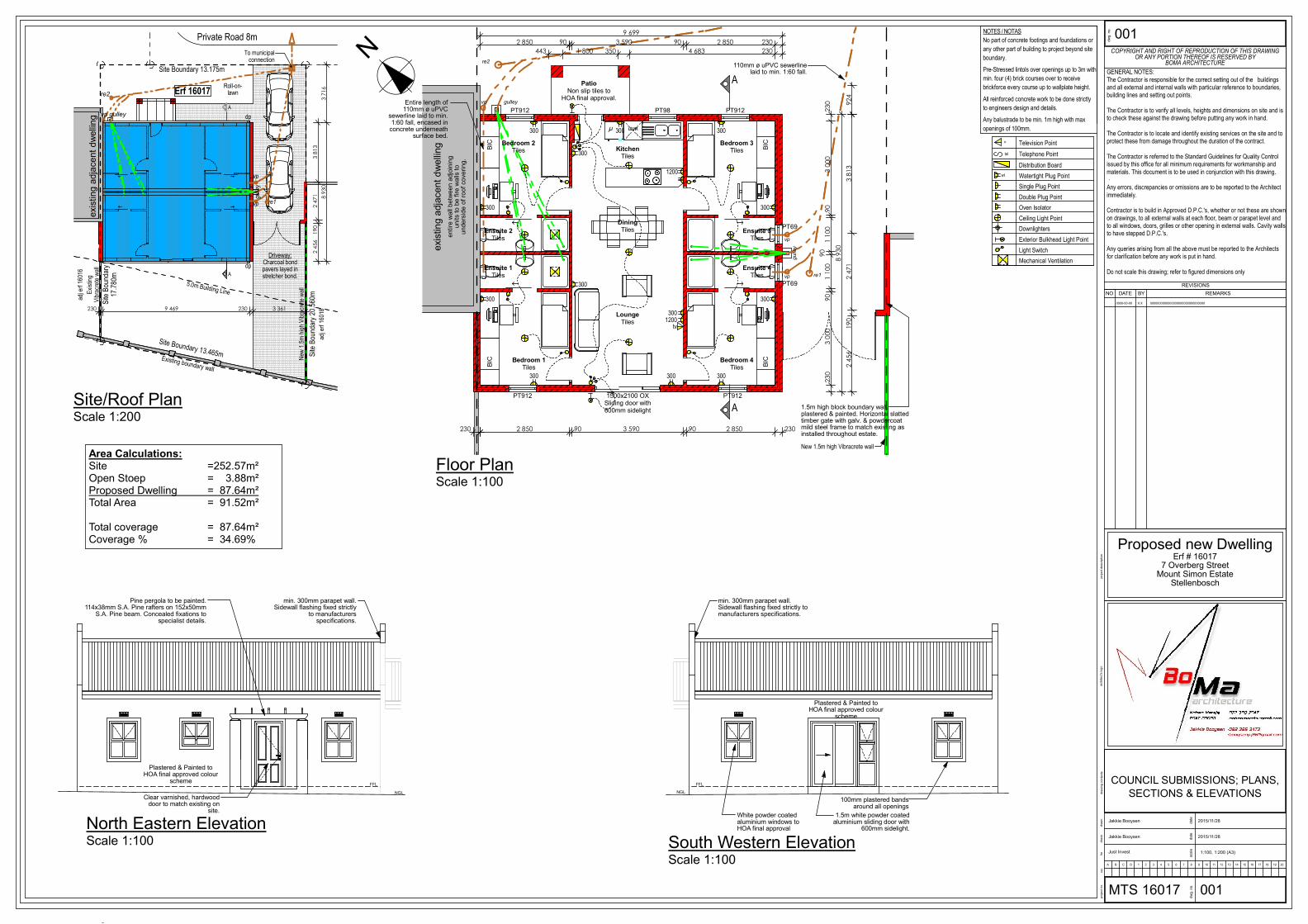
South Eastern ElevationScale 1:100
Section A-AScale 1:100
ROOF
Charcoal corrugated roof sheeting on 76x50 purlins at
900c/c on double sided "Radenshield" underlay on 150x50
trusses at 750 c/c to manufacturers specs, on 114x38 wall
plates, trusses to be tied down to walls with 1200x30
galvanised hoop iron straps embedded 600mm deep into
brickwork. 114x38 diagonal end bracing nailed to the
underside of the rafters at each end of the roof and in both
planes. 228x22mm fascia nailed to rafter ends.
PARAPET
Parapet wall to be minimum 300mm above roof finish.
Parapet to have brickforce every course.
GABLE WALLS
Gable end walls to be tied back to roof structure with
3x30mm galv hoop irons built in min 6 coarses deep in
brickwork @ max 600mm c/c.
RAINWATER GOODS
PVC gutters and downpipes
CEILING
6.5mm skimmed and painted rhinoboard ceilings fixed to
38x38 brandering at max. 400c/c fixed to the underside of
s.a pine gangnailed roof trusses. No ceiling in Garages.
STEPS
Max riser height 180mm. Min tread width 280mm.
WALLS
All internal walls to be 90mm maxi bricks. All 230mm cavity
walls to have stepped DPC at plinth level. Walls to be
plastered and painted, 1 coat plaster primer and 2 coats
topcoat.
GROUND FLOOR
Specified floor finish on 30mm screed on 100mm concrete
slab on clean sand blinding on well compacted hardcore.
FOUNDATIONS
All to Eng. detail.
GLAZING
All doors and windows with glazing larger than 1m² in area to
be 6mm safety glazing