Site Visit Report - WordPress.com 2 1. Introduction This report has been prepared for Jaime...
39
Page 1 Site Visit Report Dinton Castle August 2016
Transcript of Site Visit Report - WordPress.com 2 1. Introduction This report has been prepared for Jaime...

Page 1
Site Visit Report
Dinton Castle
August 2016

Page 2
1. Introduction This report has been prepared for Jaime Fernández, by Sam Hale, BA(Hons) MSc Historic Buildings Consultant Ty-Mawr Lime Ltd following a request to inspect Dinton Castle. This inspection was undertaken by Nigel Gervis, Technical Director and Sam Hale, Historic Buildings Consultant Ty-Mawr Lime Ltd. on 3rd August 2016.
2. Observations
History Dinton Castle is a Grade II* listed building. The listed building description records the building as follows: The sham castle or folly, now ruinous, was built as an eye catcher from the grounds of Dinton Hall in 1769 for Sir John Vanhattern to house his collection of ammonites. It is constructed of rubblestone with stone string courses, openings are mostly stuccoed architraved, except above the entrance which has a stone dressed opening. The building is of octagonal plan with circular towers at the east and west. It is 2 storeys, the towers carried up to 3 storeys. The doorway in the remains of a porch in the south face of the octagon has a depressed 2-centred brick arch. At first floor there are tall ogee headed windows. There are strings between storeys and at the base of the parapet. The parapet has now mostly gone. The towers have strings between storeys with blank pointed headed loop windows. Walls have many ammonite fossils from the local limestone beds. The interior is brick lined. The west tower had fireplaces at each storey and the east tower had a newel staircase. The building is constructed on the site of an Anglo Saxon burial ground. This is recorded in National Monument Record Number SP 71 SE 9. [SP 76531154] ANGLO-SAXON BURIAL GROUND [NR] (1) Dinton. Inhumation cemetery. Bu 33 NW. SP 765114. 1769 'In sinking a trench for the foundation of a building in the castle style' - Sir John van Hattem's Summer House, adjoining the road to Thame - at least 12 human skeletons were discovered; one skull was said to have been coated with clay. With them were a green glass cone beaker, 2 spearheads, and several other rusty pieces of iron, probably also spearheads. 1859 Akerman found 2 skeletons to the W of the summer house, lying with heads to the NW; one of a woman or boy, the other an adult man. Next day 3 more skeletons were discovered, one a woman, the others 'young people', one of whom had a buckle of bronze or etc. near the waist, unfortunately decayed. Later, Goodall excavated, but found only 2 more skeletons, one lying with head NNW, but neither with grave-goods.(2) Some of the finds are in Bucks. Co. Museum. (3)

Page 3
Dinton Castle, built as an ‘eye catcher’, was known as ‘Sir John’s Summer House’, The builder’s name was Toms; he was a mason residing at Dinton and also had a place of business at Aylesbury. The building was ruined not all that long after its construction and had been ruined well before the 1860s. It was formerly ‘in a good and habitable condition, the last occupants being an old couple of the name of Saunders, who resided in it as caretakers; they had in their younger days been servants at Dinton Hall, and were afterwards dependent on that establishment.’1
Sir John van Hatten c. 1760 – 1761
By Arthur Devis (1711 – 1787) 2
1 The Buckinghamshire Miscellany', by Robert Gibbs 1891
Ref No D 15/3 2 www.themsv.org/artwork/sir-john-van-hatten

Page 4
Unfortunately little documentary evidence survives for the original appearance of the castle roof, parapets, windows and doors or its interior. It is certain that the turrets and parapet walls were higher than they currently stand and the interior was lime plastered hard onto the stone and brick. The lack of evidence for lime plaster at first floor level could conceivably point to the fact that it may have been timber paneled. The blank lancet windows on the turrets show evidence of limewash. There are references to laying of the foundation stone in 1769, discovering the burial site, and tree-planting schemes, as well as 19th century records of burial finds3. By the 1860s the castle had already long been a ruin and a 19th century watercolour and photograph of the 1890s bear testament to this. In its picturesque ruined state in the 20th century it attracted photographers and there is a good record of the building from the early 1900s until the present day.
A watercolour of the castle by Jane Smyth (c. mid-19th century given the size of the trees). If the painting is an accurate depiction it shows the parapet had at least 10
courses of stone above the string course and could conceivably have been constructed to the height of the top string course on the turrets.4
3 Typed transcript of estate and memoranda book of the Dinton Hall Estate, giving details of house repairs, tree
planting, fish stocks and general landscaping of the estate. Buckinghamshire County Records Office Ref No D-X
612 4 Buckinghamshire County Records Office Ref No D-LE/K/27

Page 5
The castle in the 1890s, it had long been a ruin but certain elements survive then which are no longer existing today including the original central stone ogee arch with round
ammonites either side and the left hand ground floor window head. The photo also shows the parapet was at least eight courses of stone high and the stair turret had at
least four courses of stone above the top string course. 5
5 Buckinghamshire County Records Office 'The Buckinghamshire Miscellany', by Robert Gibbs 1891
Ref No D 15/3

Page 6
Dinton Castle c.1905

Page 7
Dinton Castle c.1910
c.1910

Page 8
c.1911

Page 9
c.1910s – 1920s

Page 10
c.1920s – showing a thatched hay rick, cart, and plough in the foreground.

Page 11
1932

Page 12
1936
1941

Page 13
Construction Dinton Castle is constructed of limestone and red brick laid in a rich fat lime mortar. The half-basement is constructed of limestone. The external walls are constructed of roughly coursed limestone rubble and dressed quoins. The limestone utilised is of the Portland Stone Member with occasional sandstone blocks. The structure includes many large locally-found ammonites incorporated in its external walls, they are now in poor condition due to exposure to the elements and several are missing. Brick was utilised on much of the internal walls and as external detailing around the windows and doors. Externally the brick detailing was covered in stucco, which has largely fallen off. Internally some small patches of fat lime plaster survive on the lower and upper floors. Near the castle the stone assumes the form of insulated, subglobular, or potato-shaped concretions containing great numbers of Oysters and other fossils. The building structure is generally sound as detailed by the structural engineers report. In its current state the walls will however continue to deteriorate due to moisture ingress through the tops of the walls and freeze-thaw action and wind erosion on the stonework. The limestone is soft and is eroding back. This erosion and weathering is unfortunately continuing to cause loss to architectural details such as window heads, string courses, drips and surviving fragments of lime plaster as well as the wonderful ammonites set into the walls. For the long term survival of this building and to ensure its continued existence it should be re-roofed, the parapet and turret walls capped to prevent continued water ingress and consideration given to providing drainage around the building. Being listed Grade II* works effecting its character and appearance and significance require listed building consent – as do works effecting the setting of the listed building. Grade II* status requires working with Historic England as well as the local authority. Given the important archaeological nature of the site any works involving excavations will require an archaeologist on-site. A photographic survey would be advised to be deposited in the local records office.

Page 14
This type of construction relies on the building being able to ‘breathe’ – i.e. to be able to release any moisture entering the building through weather, rising damp, living etc. See below, impervious materials, trap moisture and this build up of moisture can lead to problems associated with damp and condensation including mould growth, wet and dry rot etc. The materials considered in this report will enable the buildings to continue to work in the way that they were designed.
How solid wall buildings function

Page 15
Observations and recommendations External Notes
The external protection should retain vapour permeability while providing protection
from liquid water ingress. For a wall to be functioning well a certain amount of moisture
can be absorbed into the wall (generally the first few cms) this then dries back out with
sun and wind. If the level of protection is not adequate for the level of driving rain then
water can be absorbed further into the wall. Over several winter months with sustained
wet weather and little time for drying between wetting cycles a route of moisture can be
formed through the wall. As soon as it reaches tipping point and water ingresses into
the inside face any subsequent wetting will often draw water through to the inside
quickly and easily. This water ingress will be exacerbated by any direct routes of entry
channeling water into the wall - for example through fissures in stones, cracked mortar
and junctions in a wall. When water enters a rubblestone wall (more often than not built
with a core of earth or local aggregate bound in a weak mix and containing voids) then it
will track through the wall from the point of entry and come out in another location.
It is noted that there may be archaeological sensitivities with works involving excavations
Land drains should, if possible and permissible, be inserted actively draining into free
flowing soakaways. Any hardstanding should be dug up and land drains inserted and
vegetation cleared. Land drains should be topped with a 'soft verge' and not hard
standing..
Page 16
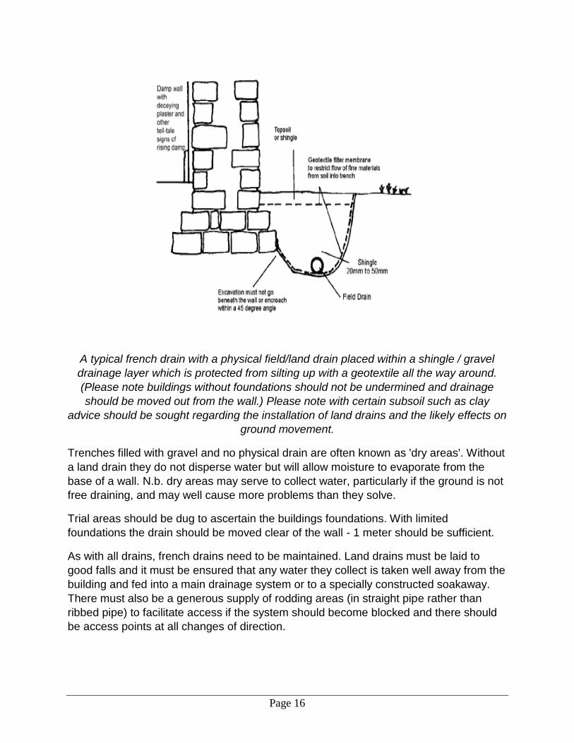
A typical french drain with a physical field/land drain placed within a shingle / gravel
drainage layer which is protected from silting up with a geotextile all the way around.
(Please note buildings without foundations should not be undermined and drainage
should be moved out from the wall.) Please note with certain subsoil such as clay
advice should be sought regarding the installation of land drains and the likely effects on
ground movement.
Trenches filled with gravel and no physical drain are often known as 'dry areas'. Without
a land drain they do not disperse water but will allow moisture to evaporate from the
base of a wall. N.b. dry areas may serve to collect water, particularly if the ground is not
free draining, and may well cause more problems than they solve.
Trial areas should be dug to ascertain the buildings foundations. With limited
foundations the drain should be moved clear of the wall - 1 meter should be sufficient.
As with all drains, french drains need to be maintained. Land drains must be laid to
good falls and it must be ensured that any water they collect is taken well away from the
building and fed into a main drainage system or to a specially constructed soakaway.
There must also be a generous supply of rodding areas (in straight pipe rather than
ribbed pipe) to facilitate access if the system should become blocked and there should
be access points at all changes of direction.

Page 17
Although the structure is sound and the thickness of the walls means that deterioration of exterior masonry will not necessarily result in collapse, the external envelope of the
building is suffering from weathering and erosion which will lead to the loss of fabric and external architectural features. Different geology of stone types has meant that
sandstone on strings and on lancet windows has stood up to weathering more than the softer limestone. The design of the ogee window heads, being too flat, has resulted in
their extensive loss – loss through poor design rather than material selection.

Page 18
The original lime mortar is still extant and survives remarkably well. This is a fat lime
mortar using a local aggregate. Small lumps of white lime in the mix suggest it was ‘hot mixed’ on site. Original lime mortar should be retained where it is still functioning and
any areas which require re-pointing should be done so in a fat lime mortar at the correct time of year (between late spring, after the last of the frosts, and early to mid-summer). Ty-Mawr Cotswold mortar – using local oolitic limestone aggregate would be advised
although we can do bespoke mixes to provide a certain colour match. The lime pointing should finish flush with the stonework not being recessed or left proud of the surface.
Samples should be trialled to be Okayed by the conservation officer.
If ammonites are to be re-bedded I would use Adhere-Vit lime adhesive mortar, and if the ammonites are of a considerable size stainless steel pins may be utilised.

Page 19
The soft limestone is delaminating across the whole of the external walls. This is only
likely to continue. For the long term survival of the building fabric and its best conservation we would suggest the walls are carefully cleaned and delaminated stone removed, the walls pointed up with a fat lime mortar and a sheltercoat of lime applied
and the building limewashed. The limewash can be made to the golden hue of the stone. There is some evidence in the blind lancet windows of a parge coat of lime and
limewash although there is little evidence on the walls that they were limewashed. Conceivably they could have been – lack of re-limewashing for 200 years+ can remove any sign that it ever existed on a building. Even if it is considered that the building had never been limewashed. The nature of the structure has now changed and the erosion and weathering of the stone would suggest that it may be best practice to now provide
much needed protection with the use of a limewash.

Page 20
The blind lancet windows which shows a parged lime coat over the brick, and evidence of a limewash. The heads are carved from a softer limestone whereas the sides and sill may be a sandstone. As a result all of the heads have suffered from extensive decay.
Keeping in with the philosophy of minimal intervention and retention of as much original fabric as possible the heads as well as other stone detailing such as the string courses,
where damaged can be repaired with lithomex stone repair mortar.

Page 21
Stone repair using stone repair mortar For surface repairs to be successful the materials employed need to have certain characteristics. They should:
Have characteristics similar to the host masonry.
Have a good modulus of elasticity.
Have adequate bond strength.
Be vapour permeable.
Be durable.
Be capable of being dressed with similar tools to the original masonry.
Remain workable long enough to allow details to be fashioned.
Match in colour and texture.
Adsorb water sufficiently in wetting and drying periods to match adjacent masonry.
They must always be reversible.
They should never:
Become significantly stronger than surrounding masonry
Have a significantly lower rate of Absorption or Adsorption than surrounding units.
Create a barrier to Diffusion. Lithomex is a specially formulated mortar based on Natural Hydraulic Lime and aggregates for the repair or simulation of masonry, brick or stone. Lithomex is a neutral white or pre coloured mortar supplied in 1KG to 25KG bags to which mixing water is added. Mixing and use: It can be mixed manually or mechanically by whisk, adding up to 180ml water per kilogram of Lithomex used. Mix well for 3-5 minutes. The application surface must be clean, free from dust and oils. On porous surfaces, ensure that suction is controlled by pre-wetting and apply Lithomex before this is fully dry. Never apply to surfaces that are over saturated or have standing water. The minimum thickness is 5mm (can be dressed or cut back to a feather edge). The maximum thickness in 1 pass is 40mm. In cases where a thickness of more than 40mm is required, apply in layers of a maximum of 40mm, each one approximately 24 hours apart. Always dampen application areas. The mortar should be well pressed back in place. If required re-compact by pressing after a couple of hours to avoid possible shrinkage marks due to suction from the background. In some instances support of the fresh mortar is required by using wires, anchorages, stainless steel fixings or formers, etc... Simulation of stone / brick features, rough finishes, false joints etc. can be made approximately 5 hours from application (in damp cold weather up to 24 hours).

Page 22
Shaping and forming of details can be carried out for up to 1 week after placing by scraping to profile or level with metal tools, such as the edge of a trowel or steel float however most shaping and finishing work can be done within 24 hours. Sculpting, using appropriate tools, requires waiting up to a week or more depending on the weather conditions. Its unique qualities allow it to be tooled, shaped and sculpted even after the final set has taken place. This affords sufficient time to achieve the very highest standard of work with the best quality reproduction. If building details are damaged and require repair prior to the facade being lime washed or painted, plain Lithomex should be used as it will readily accept lime washes and paints.
Apart from the central first floor opening which is constructed of stone other window
openings are of brick construction, rendered to simulate stone. The brick was a construction material and never intended to be seen. The polite architecture of this
structure deserves to be re-instated. Details such as this can be reinstated in prompt – a Natural Roman Cement, used extensively in conservation projects. Alternatively
lithomex could be used in this situation as well.

Page 23
The string courses, although decorative, are also functional and contain a drip detail to
throw water off the walls. For the long-term survival of the building and any new limework these string courses should be repaired to function correctly. I would envisage this would be a combination of stone repairs with a stone repair mortar and replacement
like for like where they have been irreparably damaged or where they are missing.

Page 24
Cracks such as these can be physically stitched back together by isolated re-building – using good walling techniques. An area is opened up and stone re-laid, before being
given time to set before another area is opened up and re-stitched until the whole crack is completed. Other methods include specialist helical wall ties and cintec anchors
although these can often be a little heavy handed in structures that have soft stone and will inevitably move over time. Please consult Historic England’s engineering
department.
Where brick arches require-rebuilding these should be done traditionally with a timber
former and appropriate bricks should be selected and bedded either in a fat lime mortar or, if faster setting times are required, an NHL2 mixed at 2.5 aggregate to 1 lime by
volume. Ty-Mawr Cotswold aggregate would be suitable.

Page 25
If timber windows are replaced gaps between windows and walls can be packed with hemp lime. Burnt sand mastic can be used to form joints between the timber windows and masonry. It hardens slowly but remains sufficiently flexible for the purpose. Expanded foam and silicone should not be used. Woodwork can be painted with a plant-based stand oil paint. This acrylic-free paint system moves and flexes with the timber and wears back with weathering rather than peeling and cracking. The application would be to apply 1 coat of wood primer, 1 coat of undercoat and 2 coats of stand oil thinned with balsam lacquer thinners. This can be used on windows, doors and bargeboards and can also be used on cast iron rain water goods which are first primed with red oxide. On the roof chimney stacks should be rebuilt where necessary with NHL3.5 lime mortar and flaunchings done with either NHL5 or Hourdex. These could/should be sheltercoated and limewashed the same as the walls. For added water shedding 3% raw linseed oil can be mixed into the limewash for the top coat.
Sandblasting should be avoided as this will damage the face of poor quality stone and
accelerate any decay. Careful cleaning with a stiff brush should be all that is required.
Pointing Pointing is undertaken to ensure the structural integrity and weather tightness of the structure by applying mortar into joints. It appears, luckily, that only original lime mortar survives and areas have not been re-pointed with cement. Only defective mortar should be raked out. In general this should be done by hand with a plugging chisel or tungsten tipped quirk. Power tools can occasionally be used and their success is down to the skill of the person using them. The Arbortech Allsaw with reciprocating blades has a 'heritage' blade for removal of finer mortar but this will soon become blunt on hard mortars. Excessive damage to the stone should not be tolerated. Preparing the surface ■ Loose mortar should be raked out and dust removed, usually to a depth equal to three times the width of the joint or at least 25mm. Sound mortars should be left. Great care should be taken if removing a hard mortar as damage can easily be done to the stone. A tungsten tipped quirk could be used for raking out, especially on sensitive areas to protect the arises of cut stone - otherwise a good quality plugging chisel. ■ Dampen all stones and adjoining surfaces by spraying with water or immersing in water, otherwise they will ‘suck’ the moisture out of the mortar before it carbonates/sets, causing it to fail.

Page 26
Application - fill, pin and then point! ■ Large holes should be packed with lumps of stone or bricks, as large volumes of mortar will shrink, crack and subsequently lead to failure.
Selecting pinnings (small well wetted stones/bits of tile) to reduce the amount of mortar
in rubble stonework ■ Push the mortar firmly into the joint to avoid voids in the wall.
In rubblestone walls, it is important to grout where necessary to fill any voids within the masonry structure. A grout is a lime mortar (mixed at a 2:1 fine aggregate: hydraulic lime) which is made with just enough water to make it pourable (adding casein will act as a flow additive and reduce the water demand), the walls and cracks are dampened down and the grout is then injected/pumped or poured via a funnel into mortar joints (working from the bottom up). It should be noted that large areas of grouting will introduce a large amount of water into the walls and it should be taken into account that the water will have to have time to come out. Open cavities should be pointed up with lime mortar before grouting begins. The stone mason will need to be observant, noticing and marking and monitoring weep holes until any voids within the wall are filled. Small pinning stones should be used to fill any large voids in joints prior to any re-pointing.
Injection and Grouting with Natural Hydraulic Lime
St Astier Natural Hydraulic Limes (NHL)
INJECTION - PURE LIME PUMP
NHL5 1bag + 40 liters of water Capacity: 1.1 m3 x h
NHL 3.5 1bag + 40 liters of water Pressure: 3.1 bar max.
NHL 2 1bag + 50 liters of water

Page 27
To these mixes an addition of casein can be made (1% of weight of the lime) to increase fluidity if so required. If casein is added the water addition can be reduced between 25% and 50%. Obviously NHL 2 mixes are more fluid than NHL 3.5 or 5
Use a non-cavitating whisk (1500/2000 revs per minute) to ensure total homogenization.
GRAVITY FILL MORTAR.
Sand: fine (01/02max) WATER ADDITION
NHL 5 1bag + 40 lt. of sand (55kg.approx)
Enough to obtain a paste with the required fluidity. Much less water is required if casein is added.
NHL 3.5
1bag + 40 lt. of sand (55kg. “” )
NHL 2 1bag + 50 lt. of sand (70kg. “” )
Casein addition is possible (see above).
General: where open joints in the masonry show cavities, they should be marked as reference points. Point up open joints in masonry before grouting begins. Allow to settle and top up as necessary. Leave to cure for up to 3 or 4 weeks depending on the lime grout used before removing small areas of pointing to check the cavities are completely filled. Weep holes may be required to check the grout distribution.
The addition of casein will increase the compressive strength and the set whilst improving flow and reducing the water demand. Shrinkage, already low in NHL products and mortars, will be further reduced due to the lower water content of the grout.
Page 28
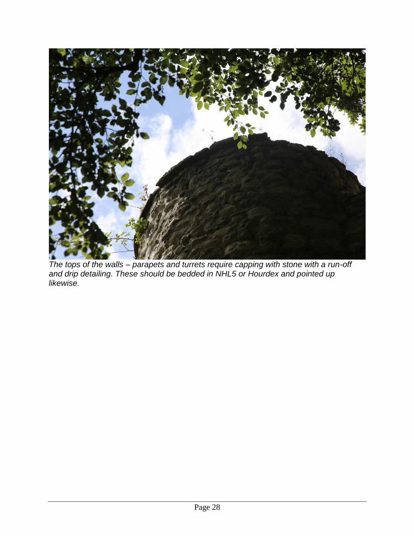
The tops of the walls – parapets and turrets require capping with stone with a run-off and drip detailing. These should be bedded in NHL5 or Hourdex and pointed up likewise.

Page 29
The base for the external staircase should be consolidated by pointing up with a fat lime mortar and capping with stone laid with NHL5.
The core of the base could be filled with Limecrete – NHL5 lime, screeding aggregate
and screed fibres mixed at 3 aggregate to 1 lime by volume. A geogrid could be introduced for more strength. This will typically reach a compressive strength of 7.2
N/mm2 and a flexural strength of 4.7 N/mm2 after 90 days. (Tests of Limecrete slabs show that they can reach compressive strengths of up to 18 N/mm2).

Page 30
After stitching the crack and re-building in stone laid in NHL2 lime mortar it is
understood a steel lintel is to be introduced to take the load of another steel to take an external staircase. The area around the steel can be back filled with a lightweight
Limecrete mix utilising pumice aggregate, NHL5 and screed fibres.

Page 31
The internal fireplaces, to be conserved and repaired with like for like materials including brick (for sourcing appropriate bricks see www.northcotbrick.co.uk or
www.colefordbrick.co.uk) set in a fat lime mortar. The rear of the fireplaces were rendered in fat lime plaster (the keyed base coat is still surviving in places) – this should be re-instated with a Ty-Mawr haired lime base coat (2x9mm coats) and a lime rich top coat plaster (1x3mm coat). Given the status and architecture of this building the brick
would have been plastered and not exposed.

Page 32
The original keyed base coat plaster.

Page 33
Where original lime plaster survives, even though fragmentary, this should be
conserved and retained – new lime plaster should be patched in around and finished with either a limewash or casein paint. The use of fixative (waterglass solution) can be
used to consolidate friable plasters.
The choice of lime plaster to re-plaster the internal walls of the building should be based on a compatible lime plaster which will allow the building to function correctly and to be of the appropriate aesthetic. Internally a fat lime plaster should be used direct onto the brick and stone. Today’s standardised haired sand and lime base coat plasters are completely compatible with this structure, but they are not necessarily that close to the lime rich plasters of the past. Other 21st century lime plasters could therefore be considered (fitting in with an honest intervention in the building). Fine lime hemp plaster is ideal to be applied onto brick and stone in coats from 6-15mm thick. It can, and in this case probably should, be finished with a 3mm fine lime top coat for a more formal finish. The hemp plaster will also provide a small level of insulation. Given the thickness of the walls and the fact that new windows will be installed the heat loss from the walls (when they are dry) will be minimal. Therefore we would suggest that an insulating plaster would be sufficient rather than introducing an insulated board system.

Page 34
To give more insulation than the hemp an ecocork lime plaster could be used as a base coat of between 20-40mm (using cork granules as the aggregate) to be topped with 6mm fine lime hemp plaster and an optional 3mm fine lime top coat. The typical u-value of a 90cm rubblestone wall with 40mm ecocork plaster would be 0.82W(m2/k) Stud partition walls With new stud walls sheep's wool insulation can be fitted between studs and clad on both sides with 15mm wood wool boards and plastered with either hemp lime base coat and sand lime top coat or sand lime base and top with a render mesh trowelled into the top 3rd of the base coat.

Page 35
Ground floor insulation For the ground floor room the insulated limecrete floor is an environmental alternative to a concrete floor and has no DPM. If the water table is high and the ground has not been drained sufficiently water can rise, hit the dpm, and go straight into the base of the walls leading to damp at low level all the way around the building. As with laying any floor (concrete or limecrete) it is best practice to deal with any ground water issues first, i.e. laying land drains around the property to take water away from the foot of the walls and if necessary with a high water table laying a land drain within the building taking it out through a doorway. Floors should not be used to cover up any ground water issues. The Ty-Mawr 'sublime' limecrete floor system, if designed and specified by us, has LABC (Local Authority Building Control) approval. This floor system has no DPM and its specified build up provides the correct engineering and insulation depths for the building. On top of the levelled and compacted ground a geotextile ‘breather’ membrane is laid followed by the insulating/hardcore layer. This layer is comprised of RFG (recycled foamed glass). The RFG has the benefits of greater compressive strength and practical advantages of laying as it can be compacted with a whacker plate and walked on while the alternative LECA balls displace when walking across them. Both materials LECA and RFG have known wicking breaks and are designed to minimum depths based on this. This means water can rise to a certain level within the insulating layer and then go back down again when the water table drops. On top of the insulating layer is another geotextile membrane followed by the limecrete screed. If in a radon area and a radon barrier is required this would take the place of the second geotextile membrane. We would advise if in a radon area that a sump is installed and actively vented otherwise there is nothing to stop the radon hitting the membrane and going into the walls. Underfloor heating can be laid on top of the RFG and a screed is laid on top with cork edge insulation against the walls to prevent heat being lost into the base of the walls. Flagstones or tiles can then be laid on top with a lime bedding mortar. The floor should when laid and cured just be treated as a concrete floor for most situations. With non-load bearing partitions just construct the walls as you would normally on a concrete floor. The same is usually true of load-bearing partitions as the load is spread. The floor slab can reach a high compressive strength for example 7.2N/mm2 after 90 days. Usual minimum depths of the floor are 120mm of the RFG insulation/hardcore with a 100mm slab.

Page 36
Limecrete floor build up. Depths are calculated by Ty-Mawr dependant on room and wall dimensions and u-value required. Assumed Sublime floor construction:-
U-value = 0.25 W/m²K
(i) 100mm Lime Screed (40mm cork installed vertically against perimeter walls).
(ii) Geogrid.
(iii) Geotextile Membrane.
(iv) 130mm Insulating Hardcore (post compaction thickness).
(v) Geotextile Membrane.
Ground.
Floor dimensions:-
Perimeter wall thickness = 1.5m
Mean depth below ground level of floor = 1.0m
Exposed Perimeter = 23.1m
Area = 20.42m

Page 37
Warm roof insulation - flat roof With a flat roof there are numerous ways of installing insulation by using woodfibre, cork or recycled foamed glass Glapor boards. With woodfibre boards you could use a Homatherm HDP Protect board.
HDP protect – is an extremely compression resistant functional board by HOMATHERM®. This wood fibre insulation board is particularly suited for flat roof construction and floor substructures. With its robust compressive strength and a raw density of 140 kg/m3, it nevertheless offers perfect thermal protection and is easily applied. With single layer laying, it creates an efficient combination of economy and excellent properties in terms of building physics.

Page 38

Page 39
Based on the following construction:- Waterproof membrane Insulation BVL 18mm plywood 150mm x 50mm joist @ 400mm centres 12.5mm plasterboard Then the achieved u-values with 120mm of the various insulations would be:- 120mm cork = 0.28 W/m²K 120mm Homatherm HDP-Q11 Protect = 0.27 W/m²K 120mm Glapor PG700 = 0.39W/m²K
Attachments:
- Choosing a lime
- Fat/hydraulic lime plasters/renders
- Fat lime mortars
- Lime hemp
- Cork plaster/render systems
- Limewash
- Casein Paint
- Burnt sand mastic
- Limecrete – sublime
- Lithomex
- Prompt
- Claypaints
- Woodfibre boards
- Cork Boards
- Recycled foamed glass
- Sheep’s wool insulation
The information provided in this report is provided in good faith after an initial visit. It is suggested that you satisfy yourself with the technical characteristics of the product for the specific applications (see published technical sheets – copies available on www.lime.org.uk) and if
necessary ask the contractor to produce samples so that the suitability, timescales and finish of the house can be finalised. Ty-Mawr Lime Ltd are
committed to providing the highest level of support to ensure a successful job, if you have any concerns at any stage of the project, please call us for advice.This report is not a surveyors report. It is based on our professional experience of assessing historic buildings over many years. Note
only limited invasive investigation was carried out, the report is based upon a detailed visual inspection.