Site-Specific Safety Plan - Davis Constructors · with good construction practices. Effective...
256
Site-Specific Safety Plan University of Alaska Fairbanks Life Sciences #10-322 Davis Constructors & Engineers, Inc.
-
Upload
vuongtuong -
Category
Documents
-
view
227 -
download
0
Transcript of Site-Specific Safety Plan - Davis Constructors · with good construction practices. Effective...

Site-Specific Safety Plan
University of Alaska Fairbanks Life Sciences
#10-322
Davis Constructors & Engineers, Inc.

Davis Constructors & Engineers, Inc.
University of Alaska Fairbanks Life Sciences Research and Teaching Facility
Project Number: 2010100LRF
Site Specific Safety Plan Job Number: 10-322
Table of Contents
Topic Tab # Emergency Contacts and Background Information 1 Policy Statement 2 Safety Policy and Procedures 3 Emergency Action, Evacuation, and Fire Protection 4 Subcontractor Health and Safety Procedures 5 Accident Prevention and Reporting Procedures 6 Hazard Communication Plan 7 Elevated Surface Work Emergency Action and Rescue Plan 8 Trenching and Excavation Procedures 9 Confined Space Procedures 10 Lockout/Tagout Procedures 11 Forklift Procedures and Training 12 Aerial Lift and Scissor Lift Procedures 13 Ladder Safety Program 14 Respiratory Protection Plan 15 Indoor Air Quality Control 16 Electrical Safety Program 17 Scaffold Safety Program 18 Steel Erection 19 Environmental Protection Plan and Control of Hazardous Materials 20 Cast In Place Concrete 21 Job Hazard Analysis 22 Forms 23

Title Page
Davis Constructors & Engineers, Inc.
UNIVERSITY OF ALASKA FAIRBANKS LIFE SCIENCES RESEARCH and TEACHING FACILITY
Project Number: 2010100LRF
Site Specific Safety Plan Job#: 10-322
Signature Sheet: Plan Preparer:
Carl Francis, Project Safety Manager
Plan Approval: Carl Swanson, Vice-President Plan Approval: Russ Kramer, Project Superintendent Plan Approval: Kirk Waggoner, Corporate Safety Coordinator

Davis Constructors & Engineers, Inc. UAF Life Science Facility 2010100LRF Site Specific Safety Plan 10-322 TAB 1: EMERGENCY CONTACTS & BACKGROUND INFORMATION
Page 1 of 1
Contract Number: 2010100LRF Project Name: UAF Life Science Research
and Teaching Facility
Description of Project & Map 101,000 SF, 4-Story above ground floors, with Mech. Penthouse, Type II FR construction, with extensive excavations for foundations and buried utilities. Map: See Attachment
Accident Experience: EXPERIENCE MOD/OSHA 300A, see attachment.
Phase of Work/Hazardous Activities:
Division 01: General Requirements
Division 02: Site Construction
Division 03: Concrete
Division 04: Masonry
Division 05: Metals
Division 06: Wood and Plastics
Division 07: Thermal and Moisture Protection
Division 08: Doors and Windows
Division 09: Finishes
Division 10: Specialties
Division 11: Equipment
Division 12: Furnishings
Division 13: Special Construction
Division 14: Conveying Systems
Division 15: Mechanical
Division 16: Electrical

Davis Constructors & Engineers, Inc. UAF Life Science Facility 2010100LRF Site Specific Safety Plan 10-322 TAB 2: ORGANIZATION AND STATEMENT
Page 1 of 2
Statement of Safety and Health Policy
The purpose of this policy for Davis Constructors and Engineers (Davis) is to develop a high standard of safety throughout all phases of our operations and to ensure no employee is required to work under any hazardous or unsanitary conditions. Davis firmly believes the individual employees have the right to derive personal satisfaction from their jobs. Consequently, the prevention of occupational injury or illness will be considered as a top priority at all times. Davis developed and maintains a complete accident prevention plan as well as the necessary safety training programs. Each individual, from top management to the jobsite craftperson, is responsible for the safety and health of those persons in their charge as well as their co-workers. By accepting mutual responsibility to operate safely, we all contribute to the safety, health, and wellbeing of all personnel. Active participation in and support of our safety commitment is essential for its success. This accident prevention written program is a living document that can and will be amended to reflect any and all changes in conditions developing as this project progresses. Davis staff and employees are aware of the potential for new hazards to develop as a project progresses, and are trained to notify management of any such circumstances or conditions as soon as identified. In addition, staff and employees understand there’s an obligation to ask questions when they do not fully understand what hazards may be associated with a specific task or procedure. Davis is committed to the belief there’s no such thing as a “stupid question” relative to safety and health issues.

Davis Constructors & Engineers, Inc. UAF Life Science Facility 2010100LRF Site Specific Safety Plan 10-322 TAB 2: ORGANIZATION AND STATEMENT
Page 2 of 2
DAVISProject Engineer Quality ControlJason Lindsey
DAVISProject AdministrationProject / Cost Controls
Schedule UpdatesAndy King
DAVISSuperintendentRuss Kramer
DAVISSafety CoordinatorSWPPP / CESCL
Carl Francis
Subcontractors / Vendors
DAVISField Personnel
UAF
DAVISProject Manager Carl Swanson

Davis Constructors & Engineers, Inc. UAF Life Science Facility 2010100LRF Site Specific Safety Plan 10-322 TAB 3: SAFETY POLICY & PROCEDURES
Page 1 of 17
Safety Policy and Procedures
1.0 Introduction 1.1 General Information A Site-Specific Safety Plan is a requirement of the OSHA Standard for Construction 29 CFR 1926. This plan is designed to identify, evaluate, and control health and safety hazards for the purpose of protecting employees. The plan provides for emergency response activities at the jobsite as well as covering site hazard analysis, training requirements, engineering controls, materials handling, and safe construction operations. This Site-Specific Plan is intended to provide guidance and information in dealing with the hazards that may be faced on the job by Davis Constructors & Engineers Inc. (Davis) employees. This plan is a site specific document. Technical, Contract and/or Operational Managers are responsible for ensuring all aspects of employee safety are addressed in this plan. Health and safety personnel are available to assist management with the contents of the plan. The health and safety personnel help ensure the plan complies with all applicable federal, state, and corporate regulations and policy. The Health and Safety Department has final authority for this plan’s contents and provisions. 1.2 Policy Davis has a strong commitment to providing a safe and productive workplace. To this end Davis seeks to establish policies promoting high standards of employee health and safety while delivering to our customer the highest quality product. In keeping with this commitment Davis intends to maintain a positive Safety Program and a Substance-Abuse Program. Our employees conduct themselves and work in a safe manner with good construction practices. Effective safety demands cooperation on everyone’s part. Its important communication is kept open at all times. For this reason, Davis management practices an open-door policy. Employees who notice hazards or other safety problems or feel they need additional training must notify their supervisor. Supervisors and management address these concerns and take corrective action when warranted.
Responsibility for achieving our safety goals belongs to the site superintendent, safety manager, supervisors, foreman,

Davis Constructors & Engineers, Inc. UAF Life Science Facility 2010100LRF Site Specific Safety Plan 10-322 TAB 3: SAFETY POLICY & PROCEDURES
Page 2 of 17
employees, with the support of Davis management. Everyone is obligated to know the safety requirements and standards for their areas or job and abide by them. Supervisors must instill a positive attitude and awareness of the “safety culture” in their workers through personal adherence, training, personal contact, and regularly scheduled safety meetings. It’s the duty of all employees to perform their work with maximum regard for their safety and co-workers’ safety. Our safety policies are an integral part of the Davis personnel policies. This means compliance with the policies is a condition of employment and must be taken seriously. Failure to comply with the Safety Program and Policy is grounds for disciplinary action up to and including termination. 1.3 Purpose
The purpose of this Site-Specific Safety Plan is to illustrate safety issues specific to the UAF LIFE SCIENCE FACILITY Project. This site safety plan is consistent with the Safety Pro-gram and Policies located in the Davis Corporate Safety Plan.
This plan is intended to maintain a safe work environment and effectively reduce the number of accidents resulting in personal injury, property damage, and damage to Davis equipment. This policy applies to all Davis employees. By contract, all subcontractors are required to comply with this policy in addition to their own safety program and policy. This policy complies with applicable local, state, and federal laws concerning safety including 29 CFR 1926 and 29 CFR 1910. In the event a discrepancy exists between this policy and any applicable law, the provisions of that law govern. This policy is made available in the following ways:
• A copy of this revised policy is made available to each newly hired employee in his/her new hire packet.
• A copy of this revised policy is available in the job site
office.
• A copy of this revised policy is available upon request to the supervisor.

Davis Constructors & Engineers, Inc. UAF Life Science Facility 2010100LRF Site Specific Safety Plan 10-322 TAB 3: SAFETY POLICY & PROCEDURES
Page 3 of 17
2.0 Scope of Project 2.1 Scope of the Work
The proposed project consists of approximately 101,000 sq. ft. of new construction. The construction consists of:
• four above-ground floors and • a mechanical penthouse of Type II Fire resistive
construction. • a utilidor modification and pedestrian access to other
buildings. • civil and mechanical installations involving excavations in
excess of 20 feet in depth. Code mandated special engineering is included in the planning and execution.
2.2 Site Location
UAF Campus – West Ridge Intersection of Koyukuk and Sheenjek Drives Fairbanks, Alaska
2.3 Site Access/Traffic During the start of construction in 2011 site access will be from Farmers’ Loop Road via North Tanana Dr. or from Geist Road via Thompson Dr. to Yukon Dr. to Sheenjek Dr. Once Davis receives approval on access and parking locations, all subcontractors and suppliers will be briefed during site orientations prior to working on the project.
2.4 Temporary Facilities
At the start of the project Davis will have a field office as well as crew and subcontractor trailers adjacent at the designated location at the corner of Sheenjek Dr. and Koyukuk Dr. Also, a tool and equipment storage trailer, fuel storage, and temporary toilets will be at this location.
2.5 Utilities and Power
Temporary electrical power will feed to the project from existing services on campus. Once the structure is substantially complete, UAF Utilities will provide permanent power and steam to the building.

Davis Constructors & Engineers, Inc. UAF Life Science Facility 2010100LRF Site Specific Safety Plan 10-322 TAB 3: SAFETY POLICY & PROCEDURES
Page 4 of 17
3.0 Health and Safety Responsibilities The effectiveness and success of the safety program depends upon the active participation and cooperation of all employees. Duties and responsibilities of all employees under this policy are the following: 3.1 Corporate Safety Coordinator
• Coordinate health and safety training for management and supervisors.
• Coordinate monthly supervisor safety meetings. • Coordinate jobsite safety audits. • Maintain and revise the Safety Policy, Corporate Safety
Manual, and Site-Specific Safety Plans as needed.
3.2 Project Safety Manager • Maintain the jobsite postings and notices required by law. • Ensure the proper filing of paperwork relating to
accidents. • Participate in post-accident investigations. • Maintain all records and reports related to this policy. • Implement Davis Safety Program and Policy including
hazard analysis and development of JHA’s prior to all preparatory meetings and associated construction activity, complete daily comprehensive, documented project inspections and direct corrective action as needed.
3.3 Project Manager
• Approve the Site-Specific Safety Plan. • Direct and coordinate health and safety regulations
related to his/her area of responsibility. • Participate in post-accident investigations. • Assist in formulating policy matters. • Implement Davis Safety Program and Policy.
3.4 Project Superintendent assisted by Project Safety Manager
• Be familiar with the health and safety regulations related to area or responsibility.
• Direct and coordinate health and safety activities within area of responsibility.
• Ensure arrangements for prompt medical attention in case of serious injury. These arrangements include, at the very least: transportation, communication, and emergency telephone numbers.

Davis Constructors & Engineers, Inc. UAF Life Science Facility 2010100LRF Site Specific Safety Plan 10-322 TAB 3: SAFETY POLICY & PROCEDURES
Page 5 of 17
• Ensure all supervised employees use required personal protective equipment (PPE) and safety devices.
• Ensure safety equipment is available, maintained, used, and stored correctly.
• Instruct and train all employees within area of responsibility in job health and safety requirements.
• Direct correction of unsafe conditions. • Conduct weekly safety meetings. • In the case of an accident complete the Report of
Occupational Injury or Illness. • Participate in post-accident investigation. • Review all accidents/incidents with foremen and
employees involved. Ensure corrective action is taken immediately to eliminate the cause of the accident.
• Ensure foremen are aware of and comply with requirements for safe practices.
• Require all subcontractors to comply with health and safety regulations as well as Davis Safety Program and Policy.
• Maintain copies of applicable programs and OSHA forms on site, in accordance with Davis practices and policies.
• Implement Davis Safety Program and Policy. 3.5 Foreman
• Be familiar with, explain, and enforce health and safety regulations applying to Davis operations within areas of responsibility.
• Direct and coordinate health and safety activities within area or responsibility.
• Ensure safety devices and proper PPE are used by employees under supervision.
• Instruct and train all employees within area of responsibility in job health and safety requirements, including (but, not limited to) hazard recognition and avoidance. Also, foreman/front line supervisors must require compliance by employees with the established safety rules.
• Direct the correction of unsafe conditions. • Ensure safety equipment is available, maintained, used,
and stored correctly. • Ensure injuries are treated promptly and reported
properly. • Participate in post-accident investigations.

Davis Constructors & Engineers, Inc. UAF Life Science Facility 2010100LRF Site Specific Safety Plan 10-322 TAB 3: SAFETY POLICY & PROCEDURES
Page 6 of 17
• Coordinate daily jobsite inspection. • Implement Davis Safety Program and Policy.
3.6 All Employees
• Be familiar with and comply with proper health and safety practices.
• Use the required safety devices and proper PPE. • Notify the supervisor immediately of unsafe conditions/-
acts, accidents, and injuries. • Implement the Davis Safety Program and Policy.
3.7 Subcontractors By contract subcontractors comply with and ensure the compliance of their employees with the provisions of this policy as well as their own safety program. Failure to fulfill this requirement is a failure to meet the conditions of the subcontract.
3.8 Key Personnel The following Davis personnel are key individuals for this jobsite.
Project Manager: Carl Swanson Safety Coordinator: Kirk Wagoner Project Superintendent: Russ Kramer
Project Safety Manager: Carl Francis Project Engineer: Jason Lindsey Foremen: TBD
4.0 Prohibited Conduct 4.1 Repairs
Employees are prohibited from making repairs, alterations, or attachments to equipment in the field except by the permission of the superintendent, foreman, or equipment mechanic. Only qualified personnel will perform repairs on equipment. Such repairs, alterations, or attachments are documented on the appropriate shop forms.
Employees are prohibited from removing a guard, safety device, or appliance from equipment or machinery except to make repairs as described in 4.1 first paragraph. While making repairs, employees use appropriate lockout/tagout procedures.

Davis Constructors & Engineers, Inc. UAF Life Science Facility 2010100LRF Site Specific Safety Plan 10-322 TAB 3: SAFETY POLICY & PROCEDURES
Page 7 of 17
When repairs are complete the guard, safety device, or appliance is replaced immediately. 4.2 Equipment Use and Operation Equipment is used only for its intended use and as recommended by the manufacturer. Using equipment for purposes other than what it’s designed for is prohibited. Employees are prohibited from operating a vehicle in a reckless manner or at a speed greater than is reasonable and proper, with due regard for weather, traffic, character of roadway, load, type of vehicle, and any other conditions which may affect the safe operation of the vehicle. The vehicle must be kept under control at all times and special care is exercised when transporting personnel. Employees using Davis vehicles must sign and abide by Davis Vehicle Policy.
Employees may only ride equipment if there are seats with seatbelts or equal protection available for each person. Seatbelts are worn at all times while operating equipment with seats.
Forklift policy and procedure are located in TAB 13 of this SSP binder. 4.3 Personal Protective Equipment (PPE) Davis provides Personal Protective Equipment (PPE) to all employees. Hard hats, safety glasses, reflective vest, and safety work boots are required to be worn at all times when on the jobsite. Exceptions may be made to this PPE requirement only under an approved Davis work plan. Employees learn where to get PPE during their new-hire orientation and are responsible for wearing and maintaining the required PPE. Additional PPE may be required depending on the task and if there’s a potential for exposure to hazardous conditions. PPE requirements are reviewed by the foreman. Employees are expected to use reasonable judgment regarding whether additional PPE (beyond the required) are necessary for certain tasks. If employees are unsure of the type of PPE required for a specific task or job, they should ask the supervisor. 4.4 Conduct The following conduct is prohibited and may result in discipline up to and including termination:
• Horseplay and scuffling on the job. • Making a false report or misrepresentation.
Davis Constructors & Engineers, Inc. UAF Life Science Facility 2010100LRF Site Specific Safety Plan 10-322 TAB 3: SAFETY POLICY & PROCEDURES
Page 8 of 17
• Fighting. • Violating the prohibitions of the Drug and Alcohol Policy
(distributed to each employee in their new-hire packet). • Dishonesty and theft of Davis property. • Deliberate misuse of Davis equipment. • Unnecessary risk taking. • Violating or disobeying any instruction given by a supervisor.
4.5 Other Policy Violations Employees committing policy violations other than those addressed in Section 4.0 may be subject to discipline up to and including immediate termination of employment. 4.6 Consequences for Policy Violations The following consequences apply to all employees found to have violated this policy. Any foreman, supervisor, or official of management, as soon as becoming aware of any such failure, ensures the following action is taken:
Stage 1
A formal verbal warning may be given to the employee by the immediate supervisor, along with a warning that this is the first stage in the disciplinary procedure and any repetition within one month will lead to the second stage in the procedure.
Stage 2
If the offense(s) addressed in Stage1 is repeated and/or continued or a more serious offense committed, the employee may be given a formal written warning, setting out the details of the offense(s) and stating if the offense(s) is (are) repeated within one month the third stage in this procedure will be invoked. In addition to the written warning the employee is suspended— without pay—for a period of one day. Upon returning to work the employee must undergo additional formal training in the area of the offense(s) before being permitted to work. This is to prevent injury to the employee or co-worker.
Stage 3
If an offense written up under Stage 2 is repeated within three months, the employee may be terminated. An employee so terminated is ineligible for rehire for 24 months.

Davis Constructors & Engineers, Inc. UAF Life Science Facility 2010100LRF Site Specific Safety Plan 10-322 TAB 3: SAFETY POLICY & PROCEDURES
Page 9 of 17
Depending on circumstances, Davis reserves the right to bypass, duplicate, or alter any stage of the recommended disciplinary procedures described above. Safety violation documents are located in Tab 23: FORMS of this SSSP binder.
5.0 General Jobsite Procedures 5.1 New-Hire Orientation New-hire orientation may consist of, but is not limited to, the
following: A. Have the employee read the new-hire packet which includes
this policy and the Drug and Alcohol Policy. Answer any questions the new hire may have about these policies and request a signature on the Statement of Understanding.
B. Return all forms to the Davis office as indicated on the first page of the new-hire packet.
C. Orient the employee to the jobsite indicating the location of the Safety Center, MSDS book, emergency facilities, portable fire extinguishers, first-aid station, emergency phone numbers, public notices, EEO, and any jobsite specific information.
D. Explain the injury and accident policy. E. Review the written hazard communication program. Discuss
hazards, container labeling, and the use of protective equipment.
F. Explain the emergency response plan for catastrophic events such as fire, explosion, etc.
G. Issue PPE as required for the job.
5.2 Training Training and education are necessary for the success of this policy. Employees are trained to recognize jobsite hazards and the procedures to follow to minimize these hazards. Training may consist of (but is not limited to) the following:
• Weekly jobsite safety meetings. • Orientation training for new hires. • Individual job/task training, including the applicable
regulations/standards for the specific job/task.
Supervisors and management receive ongoing safety training throughout the year as organized by the Safety Coordinator and

Davis Constructors & Engineers, Inc. UAF Life Science Facility 2010100LRF Site Specific Safety Plan 10-322 TAB 3: SAFETY POLICY & PROCEDURES
Page 10 of 17
as deemed necessary by Davis owners. Such training includes the maintenance of first-aid and CPR cards. Training and competent person documents are located in TAB 23: FORMS in this SSSP binder. 5.3 Safety Meetings Weekly safety meetings are held on the jobsite. All employees and subcontractors are required to attend. The meetings may cover a range of safety-related topics. The format and content of the meeting is up to the discretion of the superintendent. Monthly safety meetings are held for all foremen, superintendents, project managers, project engineers, Davis owners, and other management personnel. These meetings are for the purpose of discussing companywide safety issues and providing continued safety training and education. Safety meeting documents are located in TAB 23: FORMS of this SSSP binder. 5.4 Safety Inspections The superintendent and foreman conduct an initial safety inspection at the beginning of each project, following the “Safety Inspection Guide” included in the site-specific safety plan. In addition, a daily safety inspection of the jobsite is conducted by Davis employees, employees of a subcontractor, or some combination thereof. The inspection is rotated between all workers on the jobsite. Inspection sheets covering different aspects of safety were developed for each day of the week. The sheets are intended as a guide. Any safety concern found during the inspection is reported. If a worker is unclear about any item on the inspection sheet, a Davis foreman or safety officer helps. If the area being inspected requires a competent person1, the employee conducts the inspection with the 1 Areas requiring a competent person are hearing protection, rigging, hot work on preservative coatings, scaffolds, fall protection, cranes, hoists, excavations, concrete work requiring lift-slab operations, steel erection, underground construction, demolition, blasting, stairways and ladders, accident prevention responsibility, ionizing radiation, welding and cutting, tunnels and shafts, caissons, cofferdams, compressed air, bolting, riveting, fitting up and planking, lead, mechanical demolition, respiratory protection, slings, electrical, and asbestos.

Davis Constructors & Engineers, Inc. UAF Life Science Facility 2010100LRF Site Specific Safety Plan 10-322 TAB 3: SAFETY POLICY & PROCEDURES
Page 11 of 17
competent person. Also, if time allows, the foreman for the worker conducting the inspection is encouraged to walk through it with them. Safety inspection documents are located in Tab 23: FORMS of this SSP binder.
5.5 Hazard Communication Davis developed a written hazard communication plan. It’s explained to each employee during the new-hire orientation.
This plan is located in the site-specific safety plan appendices and is available upon request to the superintendent. The purpose of the hazard communication plan is to provide employees information on the chemical and physical hazards that may be present at the jobsite.
The Hazard Communication Plan is detailed in Tab 7: HAZARD COMMUNICATION PLAN of this SSSP binder.
5.6 Job Hazard Analysis A job hazard analysis may be developed covering the major activities of construction, the hazards associated with these activities, and ways to mitigate these hazards. The job hazard analysis procedures and forms are detailed in Tab 22 Job Hazard Analysis of this SSSP binder. 5.7 Housekeeping Housekeeping is one of the most important factors for a safe jobsite. Daily cleanup is mandatory especially for food rubbish. Form material should be scraped and all protruding nails pounded down. All other debris is cleared from work areas, passage ways, and stairs. Excess materials are stacked neatly out of the way. Tools should be stored in the tool van so they’re available for all employees to use. Combustible scrap and debris are removed at regular intervals during the course of construction. Containers with covers are provided for the collection and separation of waste, trash, oily and used rags, and other such refuse, which is removed safely and on a regular basis.
Davis Constructors & Engineers, Inc. UAF Life Science Facility 2010100LRF Site Specific Safety Plan 10-322 TAB 3: SAFETY POLICY & PROCEDURES
Page 12 of 17
Foreign object and debris (FOD) is a significant concern on research and teaching facility and construction areas. It’s extremely important to keep all trash and debris contained at this site. Housekeeping will be strictly enforced. 5.8 Alcohol and Drugs Alcoholic beverages and illegal drugs are strictly prohibited on and around all projects. No one is permitted to work under the influence of such substances and will be immediately removed and disciplined in accordance with our disciplinary policy. 5.9 Fall Protection
Davis provides fall protection when employees are exposed to fall hazards beyond those permitted by federal and/or state regulations. A fall-protection work plan is prepared for all fall hazards associated with the work. Fall protection work plan templates can be found in TAB 8: FALL PROTECTION of this binder. Fall protection may consist of, but is not limited to, the following:
• A stairway or ladder is provided at any point of access where there’s a break in elevation of 19 inches or more.
• Guardrails are installed for all leading edge work. For loading bay locations fall-arrest system or fall-restraint systems are used.
• All stairways of four or more risers or greater than 30 inches high are guarded by a handrail or stair rails.
• A hole cover or safety guardrail is immediately installed for all floor holes or openings (greater than two inches in its least dimension).
• Safety harnesses with approved lanyards and tie-off points are used for all other fall protection unless an appropriate procedure or device was approved in advance by a competent person.
The fall-protection plan is detailed in Tab 8: FALL PROTECTION AND ELEVATED SURFACE WORK EMERGENCY ACTION AND RESCUE PLAN of this SSSP binder. 5.10 Electrical Safety Electrical safety may consist of, but is not limited to, the
following: • Live electrical parts are guarded against accidental
contact by cabinets, enclosure, location, or guarding.

Davis Constructors & Engineers, Inc. UAF Life Science Facility 2010100LRF Site Specific Safety Plan 10-322 TAB 3: SAFETY POLICY & PROCEDURES
Page 13 of 17
• All receptacles not part of the permanent wiring of the building are equipped with GFCI receptacles at the temporary service drop.
• Extension cords are kept in safe, working condition. • All lamps for general illumination have the bulbs
protected against breakage. All light sockets are filled with a working bulb.
• Employees will not work in such close (able to contact) proximity to any part of an electric power circuit unless the circuit is de-energized, grounded, or guarded by insulation.
• De-energized equipment or circuits are locked out and tagged out. The tags identify the equipment or circuits being worked on.
Electrical Safety is located in TAB 17: ELECTRICAL SAFETY PROGRAM of this SSSP Binder.
5.11 Tools Davis provides tools for employees to use. These tools meet applicable OSHA standards for safety. Only trained employees are allowed to use such tools. The safe use of tools may consist of, but is not limited to the following:
• Unsafe or defective tools are removed from service and tagged out.
• Power tools are turned off and motion stopped before setting down.
• Tools are disconnected from the power source before changing drills, blades, or bits and before any repair or adjustment is made. Power saws, table saws, and radial arm saws shall have operational blade guards installed and used.
• Portable abrasive grinders have guards installed covering the upper and back portions of the abrasive wheel.
5.12 Scaffolds Scaffolds are erected, moved, dismantled, or altered under the supervision of a competent person for scaffolding. Scaffold use consists of, but is not limited to, the following procedures:
• Standard guardrails are installed on all open sides and ends of scaffold platforms and/or work levels more than ten feet above the ground, floor, or lower level.
• Scaffolds four to ten feet in height with a minimum

Davis Constructors & Engineers, Inc. UAF Life Science Facility 2010100LRF Site Specific Safety Plan 10-322 TAB 3: SAFETY POLICY & PROCEDURES
Page 14 of 17
horizontal dimension in any direction less than 45 inches have standard railings installed on all open sides/ends.
• Platforms at all working levels are fully planked. Planking is laid tight with no more than one inch space between them, overlap at least 12 inches, and extends over end supports 6-12 inches unless cleats are used.
• The front edge of all platforms is no more than 14 inches from the face of the work, except plastering/lathing may be 18 inches.
• Mobile scaffolds are erected no more than a maximum height of four times their minimum base dimension.
• Scaffold casters/wheels are locked whenever platform is occupied.
• Scaffolds are not overloaded beyond their design loadings. • Scaffold components are not used as tie-off/anchor points
for fall-protection devices. • Portable ladders, hook-on ladders, attachable ladders,
integral prefabricated scaffold frames, walkways, or direct access from another scaffold or structure are used for access when platforms are more than two feet above or below a point of access.
• Cross braces are not used as a means of access to scaffolds.
• Scaffolds are not erected, used, dismantled, altered, or moved such that they or any conductive material handled on them might come close to exposed and energized power lines than the following: - Three feet from insulated lines of less than 300 volts; - Ten feet plus for any other insulated or uninsulated lines.
Scaffold Safety is located in TAB 18: SCAFFOLD SAFETY PROGRAM of this SSSP Binder
5.13 Excavation and Trenches Excavation and trenching are done in the presence of a competent person and in compliance with, but not limited to, the following procedures:
• Any excavation or trench four feet or more in depth is provided cave-in protection through shoring, sloping, benching, or the use of hydraulic shoring, trench shields, or trench boxes. Trenches less than four feet in depth and showing potential of cave-in are also provided cave-in
Davis Constructors & Engineers, Inc. UAF Life Science Facility 2010100LRF Site Specific Safety Plan 10-322 TAB 3: SAFETY POLICY & PROCEDURES
Page 15 of 17
protection. In addition, when the work to be performed in trenches less than 4 feet in depth mandates that workers work from a kneeling or crouching position, additional protection shall be provided. Specific requirements of each system are dependent upon the soil classification as determined by a competent person.
• A competent person inspects each excavation/trench daily prior to the start of work, after every rainstorm or other hazard increasing occurrence, and as needed throughout the shift.
• An exit is provided in trenches four feet or more. The exit(s) is/are within 25 feet of any employee in the trench.
• Spoil piles and other equipment are kept at least two feet from the edge of the trench or excavation.
The excavation plan is detailed in TAB 9: TRENCHING and EXCAVATION of this SSSP binder. 5.14 Ladders Ladders are inspected during the weekly inspections to identify any unsafe conditions. Any ladders found to be unsafe are taken out of service. Extension ladders extend three feet above the work surface and are 100 percent tied off. Step ladders are only used in the open position. Ladders are stored lying down. Ladder Safety is detailed in TAB 14: LADDER SAFETY PROGRAM of this SSSP binder.
5.15 Illumination Construction areas, aisles, stairs, ramps, runways, corridors, offices, shops, and storage areas where work is in progress are lighted with either natural or artificial illumination. 5.16 Motor Vehicles and Mechanized Equipment Vehicles and equipment are only operated by qualified persons (training or experience). The superintendent maintains equipment training logs. Employees operating Davis-owned vehicles must sign and abide by Davis Vehicle Policy. All equipment operators are responsible for checking, on a daily basis, all fluid levels, drive components, and hydraulics. In addition, operators visually inspect the engine and look for structural breaks and cracks on the machine. Any and all deficiencies must be reported to a supervisor immediately. When equipment is stopped or parked, parking brakes are set

Davis Constructors & Engineers, Inc. UAF Life Science Facility 2010100LRF Site Specific Safety Plan 10-322 TAB 3: SAFETY POLICY & PROCEDURES
Page 16 of 17
and other safety precautions are taken as required for the type of equipment such as placing the forks flat on the ground. 5.17 Severe Weather
Outside construction operations including, but not limited to, steel erection, site work, and concrete work are suspended if severe wind or rain conditions present safety hazards at the worksite. Ice and snow hazards are evaluated and appropriate measures taken to abate potential hazards. The “Buddy System” will be invoked for outside work at temperatures of -40F or colder.
5.18 Accidents All accidents and near misses must be reported immediately to the foreman or superintendent. An accident report is then filled out by the employee and the supervisor. Filling out an accident report does not require the delay of medical attention. Any injury is treated first. Employees file such reports without fear of reprisal by management. The accident or incident may be discussed at weekly safety meetings or in the Safety Alert to talk about how to avoid that sort of accident in the future.
Accident prevention and investigation procedures and documents are located in TAB 6: ACCIDENT PREVENTION and REPORTING PROCEDURES of this SSSP binder.
5.19 First Aid First-aid kits are available in the project office, at the safety center and other locations as indicated during orientation. In addition, foremen and superintendents maintain current first- aid and CPR cards. CPR/First-Aid cards are on file in the Project Safety Office. 5.20 Fire Protection Davis maintains one or more fire extinguishers (rated not less than 2A) every 3000 square feet of building area, or every 100 feet. In multi-story buildings one or more fire extinguishers rated not less that 2A are provided on each floor and adjacent to the stairway(s). All trucks and equipment are fitted with portable fire extinguishers. Employees are instructed on the location and usage of these fire extinguishers. Emergency telephone numbers

Davis Constructors & Engineers, Inc. UAF Life Science Facility 2010100LRF Site Specific Safety Plan 10-322 TAB 3: SAFETY POLICY & PROCEDURES
Page 17 of 17
for fire protection and emergency medical services are posted on the field office bulletin board.
Fire Protection procedures are located in TAB 5: EMERGENCY ACTION, EVACUATION and FIRE PREVENTION of this SSSP binder.
5.21 Emergency Action Plan
Each jobsite develops an emergency action plan that’s reviewed with each employee during orientation. The emergency action plan covers emergency escape procedures, procedures followed by employees remaining to operate critical operations before they evacuate, procedures to account for all employees, rescue and medical duties, and how to report emergencies. Site maps showing site and building evacuation routes, assembly areas and other critical information will be posted on the employee bulletin board and other appropriate sites around the project. Maps, routes and assembly areas will be modified to reflect all physical changes as the project progresses.
Emergency Action Plan is located in TAB 5: EMERGENCY ACTION, EVACUATION and FIRE PREVENTION of this SSSP binder. 6.0 Safety Program and Policy Limitations
The provisions in this policy reflect decisions made by management and are not required to be approved by employees. It’s impossible to anticipate every circumstance or question about policy and include them all in this safety program and policy. Also, as time goes by, the need for revisions will arise and Davis reserves the right to revise, supplement, or rescind any portion of this policy at its discretion at any time with or without notice.

Davis Constructors & Engineers, Inc. UAF Life Science Facility 2010100LRF Site Specific Safety Plan 10-322 TAB 4: EMERGENCY ACTION, EVACUATION AND FIRE PREVENTION
Page 1 of 11
Emergency Action, Evacuation, and Fire Prevention
1.0 Purpose The purpose of this Emergency Action Plan (EAP) is to ensure employee safety from fire and other emergencies. This written document is prepared to demonstrate compliance with 29 CFR 1910.38. It provides a written document detailing the actions and procedures to be followed in case of an emergency. At the time of an emergency, employees should know what type of evacuation is necessary and their responsibilities in carrying out the plan. In some cases the emergency is grave requiring total and immediate evacuation of all employees in necessary. In other emergencies a partial evacuation of non-essential employees with a delayed evacuation of others may be necessary. In some cases, only employees in the immediate area of a fire may be expected to evacuate or move to a safe area such as when a local application of a fire suppression system discharge sounds the employee alarm. Employees must ensure they know what’s expected of them in all such emergency possibilities which were planned in order to provide assurance of their safety from fire or other emergencies. This plan contains the information required for employee knowledge.
2.0 Types of Emergency Evacuations At this location the following types of potential emergencies exist:
1. Evacuation of seriously injured personnel. 2. Fire or explosion. 3. Earthquake 4. Building collapse. 5. Encountering combustible or toxic gases. 6. Other emergencies.
3.0 Employee Training All employees are trained in safe evacuation procedures and refresher training is conducted whenever the employee’s responsibilities or designated actions under the plan change and whenever the plan itself is changed. In addition, the employer must review with each employee

Davis Constructors & Engineers, Inc. UAF Life Science Facility 2010100LRF Site Specific Safety Plan 10-322 TAB 4: EMERGENCY ACTION, EVACUATION AND FIRE PREVENTION
Page 2 of 11
(upon initial assignment) the parts of the plan the employee must know to protect the employee in the event of an emergency. Every individual is responsible for immediately correcting and/or reporting any hazard or unusual condition that might lead to the development of a fire or emergency situation. All individuals are responsible for knowing:
1. In an emergency call 911. 2. Location of emergency phones and fire alarm 3. Location of emergency equipment. 4. Location of safe-briefing area for evacuation.
The training may include the use of floor plans and workplace maps which clearly show the emergency escape routes included in the Emergency Action Plan.
4.0 Floor Plans and Maps Floor plans and workplace maps were developed for this location to show the emergency escape routes. Color coding aids employees to determine their escape route assignments. These floor plans and maps are available and posted at all times in the key areas of the jobsite to provide guidance in an emergency. A copy of the floor plans and map are located in Appendix 1. Note: Floor plans and maps may not be available at the beginning of this project.
5.0 Response to Accidents Involving Injuries
5.1 Use of the acronym: SAVE. The following steps should be followed to respond to injuries resulting from accidents:
Situation: Quickly assess the situation to determine if any hazards exist, the extent of the injury, and to decide the best mode of response.
Activate: 1. If the injured person has serious injuries or is not respond-
ing, immediately call or direct a person to call 911. The caller needs to stay on the line and give responder pertinent information e.g. location and street address, nature of injury, conditions, number of persons involved. Jobsite

Davis Constructors & Engineers, Inc. UAF Life Science Facility 2010100LRF Site Specific Safety Plan 10-322 TAB 4: EMERGENCY ACTION, EVACUATION AND FIRE PREVENTION
Page 3 of 11
identification hardhat stickers with job address and phone numbers are given to all new employees.
2. Notify site superintendent/management to start emergency action plan. Radio call is: code RED.
Site management:
• Management sends personnel to direct emergency respond-ers to the accident scene: one person at the street and one at building entrance.
• Moves excess equipment out of the way. • Secures the scene for an accident.
Verify: 1. Verify the extent of injury. 2. Stabilize and prevent movement (if necessary). 3. Render first aid using proper PPE e.g. protective gloves, CPR,
mouth shield. 4. Treat for shock (keep injured worker warm). 5. Stay with the injured worker until emergency services arrive. 6. Assist emergency personnel upon arrival.
Evaluate: Investigate the accident. (See Accident Reporting in site safety manual.) Note: Davis Safety Policy requires a post-accident/incident investigation be performed for all injuries beyond first aid. Drug testing is required when the injury:
1. Involved circumstances leading to a reasonable suspicion of the employee’s drug use.
2. Results in or causes the release of hazardous waste or materials, or
3. Involves an on-the-job injury or potentially serious accident, injury, or incident in which safety precautions were violated, equipment or property was damaged, or unusually careless acts were performed. Such testing is required of any employee directly involved in such an incident and whose action or inaction may have been a causative factor.
Supervisors must consult with corporate safety/risk management for guidance on drug screening.

Davis Constructors & Engineers, Inc. UAF Life Science Facility 2010100LRF Site Specific Safety Plan 10-322 TAB 4: EMERGENCY ACTION, EVACUATION AND FIRE PREVENTION
Page 4 of 11
6.0 Emergency Escape Procedures and Assignments The following are the evacuation procedures for a fire, earthquake, building collapse, and/or any other emergency:
1. Stay calm! Your example can influence others and thereby aid the emergency response.
2. Employees proceed to the nearest available and safe exit and leave the building as quickly as possible in the event of a fire or other emergency requiring evacuation to achieve safety.
3. As a matter of general practice, corridors (if applicable) are the primary means for evacuation from a building.
4. Personnel operating moving machinery e.g. trucks, forklifts, etc. are to depress the closest emergency stop button (if applicable) or park the vehicle to the side immediately.
5. Personnel are to gather at a “refuge zone.” The refuge zones
provide sufficient space to accommodate the employees. During evacuation procedures employees move away from the exit discharge doors of the building and avoid congregating close to the building(s) and/or main entrance area where they may hamper emergency operations.
6. The safe-briefing areas are equipped with first-aid equipment to
treat any injured employees.
7. No one is allowed onto the jobsite during this time without consent from Davis supervisory personnel.
8. Once assembled no one is permitted to leave the safe-briefing site
without consent from Davis supervisory personnel.
9. After the determination is made that re-entry is safe by the fire department or the evacuation coordinator employees may re-enter the building or jobsite.
The refuge/safety zones are as follows: Contractor Laydown Yard or the Contractor Office Trailer Complex
Davis Constructors & Engineers, Inc. UAF Life Science Facility 2010100LRF Site Specific Safety Plan 10-322 TAB 4: EMERGENCY ACTION, EVACUATION AND FIRE PREVENTION
Page 5 of 11
7.0 Critical Site Procedures Only in the event of an incipient fire will employees address the fire and care for critical site operations. If the fire exceeds the incipient fire stage, the employee is to evacuate the area immediately. The procedures to be taken to care for essential jobsite operations until a total evacuation becomes absolutely necessary include:
• Monitoring the jobsite power and water supplies, and,
• Vehicle/utility operations which must be shut down in stages or steps to ensure the safe shut down procedures are completed including the following:
Indicate procedures which must be shut down in stages/steps
e.g. pick-up or delivery in process, filling of containers, etc: 1. Equipment operations 2. Material movement 3. Subcontractor utility 4. Fueling
8.0 Evacuation Procedures The superintendent in conjunction with the Project Safety Manager anticipates the effect of a major emergency or disaster for each specific jobsite and plans a course of action minimizing personal injury and property damage in the event of fire, industrial hazard, or natural disaster. If evacuation of the jobsite and/or building(s) is required, the following procedures are followed ensuring safe evacuation of all employees, contractors, and/or visitors.
1. The evacuation coordinator (default to superintendent, Project Safety Manager or foreman) verifies an emergency situation truly exists. If so, UAF fire department or emergency service is notified.
2. The evacuation coordinator utilizes the alarm system or a means of
communication e.g. bull horn, public-address system, radio, etc. to effectively communicate that evacuation of the building and/or jobsite is required.
Davis Constructors & Engineers, Inc. UAF Life Science Facility 2010100LRF Site Specific Safety Plan 10-322 TAB 4: EMERGENCY ACTION, EVACUATION AND FIRE PREVENTION
Page 6 of 11
3. The evacuation coordinator verifies the visitor/subcontractor log is removed from the building/jobsite.
4. The evacuation coordinator conducts a head count to verify all
employees, subcontractors, and/or visitors are safely evacuated.
5. The evacuation coordinator communicates to the fire department either that all personnel are safely evacuated or who remains unaccounted for.
6. No one may return to the building or jobsite until the evacuation
coordinator or fire department authorizes such action.
9.0 Rescue and Medical Duty Assignments If rescue is required, the local fire department responding to the emergency is responsible for performing any rescue. Designated personnel (trained in first aid and cardiopulmonary resuscitation, CPR) provide medical assistance within their capabilities. Trained personnel are:
List trained employee’s names here: Carl Francis Jason Lindsey ________________________ ________________________ ________________________ ________________________
Professional emergency services responding to an emergency assist with and direct all rescue and medical duty assignment upon their arrival.
10.0 Fire and Emergency Reporting Procedures In the event of a fire and/or any other type of emergency follow these reporting procedures:
1. When a fire is detected (seen, heard, smelled, etc.) alert everyone in the near vicinity and radio or otherwise inform the fore-man/supervisor (if applicable).

Davis Constructors & Engineers, Inc. UAF Life Science Facility 2010100LRF Site Specific Safety Plan 10-322 TAB 4: EMERGENCY ACTION, EVACUATION AND FIRE PREVENTION
Page 7 of 11
List locations of alarm stations (if applicable):
Air horns will be located on each fire extinguisher stand.
Five (5) consecutive blasts for any emergency. _____________________________________________________ _____________________________________________________ ____________________________________________________
2. Jobsite personnel (supervisor/foreman, evacuation coordinator, employee if needed) are to verify the alarm is indicating an emergency. If so, they contact the local fire department to summon assistance.
3. The local fire department performs all emergency rescue and fire
fighting duties. The evacuation coordinator meets with the fire department to notify them of any missing persons.
4. Employees are not to return to the jobsite or buildings until
authorized by the evacuation coordinator or fire department.
11.0 Earthquake Procedures If an earthquake warning is issued by local news services(s), the evacuation coordinator notifies all employees. If an employee notices earthquake indicators (shaking ground, swaying or falling objects) that employee evacuates to a pre-disclosed earthquake safety/shelter area. The area(s) designated to provide shelter/protection during an earthquake are: List area(s) designated as earthquake shelter for personnel: TBD_____________________________________________ ________________________________________________ ________________________________________________

Davis Constructors & Engineers, Inc. UAF Life Science Facility 2010100LRF Site Specific Safety Plan 10-322 TAB 4: EMERGENCY ACTION, EVACUATION AND FIRE PREVENTION
Page 8 of 11
12.0 Evacuation Coordinator
Selected personnel are trained as evacuation coordinators conducting head counts of employees once evacuation is complete. At least one trained evacuation coordinator for every twenty employees on the jobsite is available to provide adequate guidance and instruction at the time of an evacuation. The employees selected are trained in the complete jobsite layout and various alternative escape routes from the jobsite. All evacuation coordinators are made aware of:
o Any physically handicapped employees requiring additional assistance and of hazardous areas to be avoided during emergencies.
o Any visitors/subcontractors or personnel not permanently assigned to work at this jobsite.
Before leaving the jobsite evacuation coordinators ensure all personnel are evacuated from the jobsite and verify that all rooms and other enclosed spaces in the building are empty. Evacuation coordinator(s) for this jobsite are:
Job Title Area Work Shift Russ Kramer, Superintendent TBD 7:00 a.m. to 6:00 p.m.
Carl Francis, Project Safety Manager TBD 7:00 a.m. to 6:00 p.m.
13.0 Fire Prevention Plan The Fire Prevention Plan was established to control and reduce the possibility of a fire and to specify the type of equipment required to be available in case of a fire.
13.1 List of Workplace Fire Hazards and Procedures

Davis Constructors & Engineers, Inc. UAF Life Science Facility 2010100LRF Site Specific Safety Plan 10-322 TAB 4: EMERGENCY ACTION, EVACUATION AND FIRE PREVENTION
Page 9 of 11
The fire hazards in this location are:
Hazard Type Location Procedures
Lumber stock piles Storage area
Keep covered and keep smoking area and hot running equipment at distance.
Paint, aerosol cans
Flammable storage cabinet
All flammable paint containers and aerosol cans are to be stored in “flammable storage.”
Office paper
Office supplies
Offices
Keep amount of paper on hand to a minimum. Ensure all trash containers are empties every day.
Fuel: Gasoline
Diesel
Fuel storage area
Follow all OSHA regulations (keep stored upright, away from other fuel, in cool area, etc.)
Flammable material/ chemicals
Specially designated storage area.
Keep separated and away from sources of heat. Otherwise follow above instructions.
Tools and other elec-trical equipment Tool storage.
Keep closed when possi-ble. Keep things up above floor so no water gets on them. Also, keep smoking area safely away.
13.2 Housekeeping Procedures Accumulations of combustible waste materials must be controlled to ensure a fast-developing fire, a rapid spread of toxic vapors or gases, or an explosion does not occur. Large accumulations of combustible waste materials can cause a large fire or generate dense smoke. Good housekeeping in the workplace ensures hazardous accumulation of oil soaked rags and/or large accumulations of wastepaper, corrugated boxes, etc. do not pose a significant fire hazard.

Davis Constructors & Engineers, Inc. UAF Life Science Facility 2010100LRF Site Specific Safety Plan 10-322 TAB 4: EMERGENCY ACTION, EVACUATION AND FIRE PREVENTION
Page 10 of 11
13.3 Equipment Maintenance (if applicable) Certain equipment is installed in a workplace to control heat sources or to detect combustible fuel leaks e.g. a temperature- limit switch, storage tank high level alarms, etc. If these devices are not properly maintained or if they become inoperative, a definite fire hazard exists. Employees and supervisors are aware of the specific type of hazard-control devices utilized in the workplace and they ensure (through periodic inspection and/or testing) such devices are operable. The manufacturer’s instructions are followed ensuring proper operation and maintenance procedures are followed.
13.4 Ignition Sources and Fire Protection The ignition sources at this location and their control procedures at this location are:
Ignition Source Control Procedure 1. Electrical Periodic inspection of equipment. Dry,
clean storage. 2. Flame Heaters Safely distanced from everything around. 3. Welding Observation and wetting of things around. 4. Cigarette butts Smoke only in designated areas.
5. Hot-running equipment Keep distance from other objects and observation.
Also, smoking is only allowed in designated smoking areas of this location. The designated smoking area(s) for this location are: Designated Smoking Area: Area(s) assigned by site superintendent.
13.5 Fire Protection Equipment The fire protection equipment utilized at this location includes various sizes of multipurpose dry chemical (aka, ABC) portable fire extinguishers to protect from the various types of fire hazards. Employees are trained on site with the location and usage of portable fire extinguishers.
Davis Constructors & Engineers, Inc. UAF Life Science Facility 2010100LRF Site Specific Safety Plan 10-322 TAB 4: EMERGENCY ACTION, EVACUATION AND FIRE PREVENTION
Page 11 of 11
Appendix 1
Floor plans and maps here.

Davis Constructors & Engineers, Inc. UAF Life Science Facility 2010100LRF Site Specific Safety Plan 10-322 TAB 5: SUBCONTRACTOR HEALTH & SAFETY PROCEDURES
Page 1 of 10
Subcontractor Health and Safety Procedures
1.0 Policy Davis Constructors & Engineers, Inc. (Davis) policy is to select, contract with, and oversee subcontractors with the same priority and emphasis on safety as we practice. It’s a contractual requirement that subcontractors comply with Davis, client, state, and federal safety and health regulations.
2.0 Purpose and Scope All contractors and employees on a project can only achieve the goal of an accident-free jobsite through a cooperative effort. This procedure provides guidelines used by Davis management when selecting subcontractors as well as safety requirements implemented when subcontractors and their employees begin work on Davis projects.
This procedure applies only to subcontractors who have a contractual relationship with Davis and their tier subcontractors.
3.0 Definitions
Term Definition
Subcontractor Any person, partnership, or corporation with a contract with Davis and/or their subcontractor(s) to furnish labor, material, or equipment as part of the work
Work The total of the contractor’s responsibilities as set forth in the contract documents.
Superintendent The highest-ranking representative of Davis whose regular work location/office is on the project site.
4.0 Responsibilities The Project Manager, project engineer, and superintendent are responsible for the selection of subcontractors. The Safety Department is available as a resource to interpret safety data and provide assistance in the selection of subcontractors as required. The Project Manager and superintendent and the project staff are responsible for assuring the

Davis Constructors & Engineers, Inc. UAF Life Science Facility 2010100LRF Site Specific Safety Plan 10-322 TAB 5: SUBCONTRACTOR HEALTH & SAFETY PROCEDURES
Page 2 of 10
overall implementation of and compliance with the requirements of this procedure through the subcontractor management/supervisor chain of command.
5.0 Training Subcontract employees must complete safety training complying with all applicable federal, state, local, client, and Davis safety requirements. Documentation of all safety training is maintained on the project by the subcontractor and provided to Davis upon request.
Under federal and state safety requirements subcontractors (employers) must certify all operators of mobile equipment, such as forklifts, cranes, boom lifts, buses, etc., are trained and/or certified on the proper operation of the equipment. Copies of this training and certification are maintained on the project by the subcontractor and forwarded to Davis upon request.
All subcontractor employees are required to participate in weekly safety training sessions. Signed copies of the weekly meeting reports are made available to Davis within 24 hours of each session.
6.0 Inspection and Storage Copies of all subcontractor safety documents are maintained for a minimum of 12 months, unless a specified longer retention time is required by a regulatory agency.
Accident reports, OSHA logs, and other critical safety documentation become part of the permanent project files and maintained by Davis at project completion.
7.0 Procedure Requesting and evaluating subcontractor general safety plan:
• The Project Manager, Superintendent or Project Safety Manager will request a subcontractor general safety plan from all potential subcontractors in conjunction with a request for quotation for services.

Davis Constructors & Engineers, Inc. UAF Life Science Facility 2010100LRF Site Specific Safety Plan 10-322 TAB 5: SUBCONTRACTOR HEALTH & SAFETY PROCEDURES
Page 3 of 10
• Upon return receipt, the general safety plan is reviewed by the Project Manager, Superintendent and Project Safety Manager to determine if the subcontractor has a safety program meeting acceptable guidelines for performing the work.
• Subsequent to review of the general safety plan, the Project Man-
ager, Superintendent or Project Safety Manager jointly qualify or disqualify a subcontractor. Three primary sources of information provide ways to evaluate the probable safety performance of prospective subcontractors:
1) Experience modification rates for worker’s compensation
insurance premiums.
2) OSHA incidents rates for recordable injuries and illnesses.
3) Contractor safety programs, procedures, and practices.
Note: Due to the vast number of variables that may impact safety measurement systems, Davis has no standard minimum or set safety criteria for disqualifying potential subcontractors.
7.1 Documentation and Reporting Requirements Every subcontractor’s employee is required to review all relevant elements of the Davis Site Specific Plan and acknowledge said review by signature.
Prior to mobilizing the project, all subcontractors are to forward a copy of their safety program and hazard communication program to the Project Safety Manager.
Subcontractors must generate a Hazard Assessment Safety Action Plan, specific to their scope of work and completed before mobilizing the project. The Project Safety Manager reviews the plan.
Subcontractors are required to participate in producing task-specific hazard analysis for daily activities as well as review all site safety reports.

Davis Constructors & Engineers, Inc. UAF Life Science Facility 2010100LRF Site Specific Safety Plan 10-322 TAB 5: SUBCONTRACTOR HEALTH & SAFETY PROCEDURES
Page 4 of 10
Signed copies of subcontractor’s weekly safety meeting reports are made available to Davis within twenty-four (24) hours of each meeting.
Accident investigation reports for all subcontractor accident, injuries, and work-related illnesses are forwarded to the Davis site superintendent within twenty-four (24) hours of the occurrence.
Subcontractors provide a Monthly Summary of Injuries for each month in which they conduct work on the project. These reports are due to the Davis site safety manager by the fifth (5th) day of the month for the past month.
Subcontractors are also responsible for and comply with all federal and state accident reporting and recordkeeping requirements for their employees.
Each subcontractor develops a project specific emergency action plan in accordance with federal, state, client and Davis requirements.
Site management must be informed promptly of any accident occurring on the project. Serious injuries, illnesses or any accident involving a third party or a member of the general public must be reported to Davis site management immediately.
Site management must be informed immediately of any OSHA, EPA, or other safety or health regulatory agencies actions involving the subcontractor’s work.
7.2 Basic Safety Requirements The following basic safety rules list some of the Davis primary safety concerns for subcontractor safety, but are in no way all-inclusive. All other client, owner, Davis, federal, state, and local safety and health regulations governing the work applies.
Each subcontractor appoints an on-site safety representative who attends Davis scheduled project safety meeting and is responsible for implementation of rules listed below, as well as any other safety rules determined necessary for the safe execution of the project as decided by Davis.

Davis Constructors & Engineers, Inc. UAF Life Science Facility 2010100LRF Site Specific Safety Plan 10-322 TAB 5: SUBCONTRACTOR HEALTH & SAFETY PROCEDURES
Page 5 of 10
Rules: • Hard hats are worn at all times. This includes welders when
using welding hoods, and all visitors.
• Sleeved shirts are worn at all times. (No tank tops.)
• Hard-toe, leather work boots, are worn at all times.
• Safety glasses (with rigid side shields), designated ANSI Z87.1, are worn at all times. This includes under welding hoods and employees with prescription eye wear.
• Face shields must be worn in conjunction with safety glasses
when grinding, chipping, jack hammering, power sawing, or conducting other tasks involving serious face/eye hazards.
• Gloves, appropriate for the hazard present, are worn when
hands are exposed to absorption of harmful substances, cuts, abrasions, punctures, chemical burns, thermal burns or harmful temperature extremes.
• All subcontractor employees comply with the Davis Fall-
Protection Policy. This policy simply states: “Anytime employees are working from an unprotected elevation of six (6) feet or more, fall protection must be used.” Working as stated above means while traveling, stationary, or at any time exposed to a fall from a surface not protected by approved handrails, guardrails or some other approved fall-arrest device.
• Good housekeeping is maintained on a continual basis.
Supplies, tools, materials, scrap material and construction debris are stored, transported, signed, contained and disposed of properly.
• Hearing protection is worn when employees are exposed to
noise levels requiring protection, as defined by OSHA safety standards.
• Illegal drugs, alcohol, firearms, fireworks or other dangerous
substance are not allowed on the project and may result in permanent dismissal.
Davis Constructors & Engineers, Inc. UAF Life Science Facility 2010100LRF Site Specific Safety Plan 10-322 TAB 5: SUBCONTRACTOR HEALTH & SAFETY PROCEDURES
Page 6 of 10
7.3 Drug and Alcohol Compliance Drug or alcohol usage or impairment on the worksite is not tolerated. Such impairment may risk injury or death to the impaired worker and/or co-workers. For the safety and protection of all jobsite workers, subcontractors must agree to mandate its employees to subject themselves to reasonable suspicion drug and/or alcohol testing when:
a. Any subcontractor manager or superintendent has a
reasonable suspicion of drug or alcohol usage or impairment.
b. Davis superintendent or designee has a reasonable suspicion
that any subcontractor employee may be in violation of the zero-tolerance drug and alcohol policy or appears impaired and such impairment could adversely affect job safety and/or performance.
Davis Drug and Alcohol Policy is posted at the jobsite and on the “Subcontractor” page of Davis website, www.davisconstructors.com this page is password protected. The password is: subp@ge.
7.4 Equipment All equipment brought onto the project will, at a minimum, comply with Davis, state, and federal OSHA regulations. All equipment inspections shall be properly documented and maintained on site.
All equipment on the project is used in accordance with both federal and state safety requirements and the manufacturer’s instructions and guidelines. Equipment shall not be altered in any way for a use for which it’s not intended.
An inspection program and schedule are implemented for all equipment used on site, as required by applicable safety regulations. Documentation of these inspections are maintained by the subcontractor and provided to Davis upon request.
A scaffold tagging program is enforced on all projects. All subcontractor scaffolds are required to have a scaffold tag attached indicating the subcontractor’s:
• name, • date,

Davis Constructors & Engineers, Inc. UAF Life Science Facility 2010100LRF Site Specific Safety Plan 10-322 TAB 5: SUBCONTRACTOR HEALTH & SAFETY PROCEDURES
Page 7 of 10
• status of scaffold safety requirements and • any additional items that may be needed before using the
scaffold.
Subcontractors use either Ground Fault Circuit Interrupters (GFCI’s) or an assured equipment grounding inspection program to protect employees using electrical tools and equipment.
7.5 Certification and Permits
Certain operations may require a Client/Owner permit. The subcontractor representative inquires with Davis site management to determine if any of the subcontractor’s activities require a Client/Owner permit. Such activities may include, but are not limited to:
• Hot Work • Confined Space • Excavations
Various state and local authorities require permits for specific activities such as excavations, heavy lifts, lead abatement, scaffolding, etc.
7.6 Hazard Communication Program All subcontractor companies are required to have a written Hazard Communication Program meeting federal, state, and OSHA requirements and comply with the program. A copy of the program is forwarded to the Davis site management and a copy is required to be in the possession of the subcontractor on the site. The employer must complete documentation of employee Hazard Communications Training prior to the commencement of work.
Any potentially hazardous material or chemical brought onto the project must have a Material Safety Data Sheet (MSDS). Copies of the MSDS’s shall be forwarded to the Project Safety Manager before the product is brought on to the project. Small quantities of hazardous liquids, such as gasoline, diesel fuels and any solvents, brought onto the project are stored in a properly labeled safety container with a flame arrestor and self-closing lid. All hazardous materials and chemicals brought onto the project are in the proper containers with no visible signs of leaks. Contact site management prior to bringing large quantities of hazardous materials or liquid on site.

Davis Constructors & Engineers, Inc. UAF Life Science Facility 2010100LRF Site Specific Safety Plan 10-322 TAB 5: SUBCONTRACTOR HEALTH & SAFETY PROCEDURES
Page 8 of 10
All containers brought onto the project must be labeled as to their contents.
Site management is notified before any chemical/material creating noxious or toxic fumes is used.
7.7 Respiratory Protection All subcontractors, whose employees may be expected to wear a respirator, send a copy of their written Respiratory Protection Program to Davis site management. The program must comply with current Davis, state, and federal requirements. A Respiratory Protection Program must address the following:
• Proper respirator selection, • Proper respirator training and the required fit-test
procedures, • Proper respirator cleaning, sanitizing, inspection and main-
tenance, • Respirator users’ medical clearance.
7.8 Safety Surveys Site management and the Project Safety Manager conduct periodic safety surveys of projects. Any safety discrepancy observed is reported to the appropriate subcontractor’s site safety representative for immediate resolution.
Davis safety surveys do not relieve subcontractors of their responsibility to self-inspect their work and equipment. All subcontractors—at all times—conduct their work in a safe manner.
7.9 Safety Adherence Davis understands the discipline of subcontractor personnel is the responsibility of subcontractor management. When observed, however, Davis documents violations of safety policies and forward said documentation to the subcontractor’s representative. After verbal and written notices are documented and if the subcontractor repeatedly fails to comply, the employee may be removed from the worksite (as outlined by the procedures below).
Davis Constructors & Engineers, Inc. UAF Life Science Facility 2010100LRF Site Specific Safety Plan 10-322 TAB 5: SUBCONTRACTOR HEALTH & SAFETY PROCEDURES
Page 9 of 10
7.9.1 Consequences for Policy Violations The consequences discussed below apply to all employees/-subcontractors found in violation of this policy. Any foreman, supervisor, or official of management after becoming aware of any such failure ensures the following action is taken:
Stage One
A formal verbal warning may be given to the employee by his/her immediate supervisor, along with a warning that this is the first stage in the disciplinary procedure and any repetition within one month will lead to the second stage in the procedure.
Stage Two
If the offense(s) addressed in Stage 1 is repeated and/or continued or a more serious offense is committed, the employee may be given a formal written warning setting out the details of the offense(s) and stating that if the offense(s) is (are) repeated within one month, the third stage in this procedure is invoked. In addition to the written warning, the employee is suspended without pay, for a period of one day. Upon his/her return to work the employee must undergo additional formal training in the area of the offense(s) before being permitted to work in order to prevent injury to the employee or co-workers. Stage Three If an offense identified in Stage 2 is repeated within three months, the employee may be terminated. An employee so terminated is ineligible for rehire for 24 months. Note: Depending on circumstances, Davis reserves the right to bypass, duplicate, or alter any stage of the recommended disciplinary procedures described above.
7.10 Imminent Danger Upon discovery of any situation which may (in the opinion of the site management or safety representative) lead to a serious injury, illness, or death site management or safety immediately suspends the related work. Work may resume only after the safety concern(s) is corrected to the satisfaction of Davis.

Davis Constructors & Engineers, Inc. UAF Life Science Facility 2010100LRF Site Specific Safety Plan 10-322 TAB 5: SUBCONTRACTOR HEALTH & SAFETY PROCEDURES
Page 10 of 10
Examples of “imminent danger” situations may include, but are not limited to, the following:
• Falls from elevations exceeding Davis, federal, or state safety
standards. • Excavation not properly sloped or shored. • Possible electrocution hazards to the general public. • Operations of vehicles, machinery, or heavy equipment in an
unsafe manner.
Other than immediate suspension of work the procedure for correction of imminent danger situations follows the procedure set forth in section 7.9.

Davis Constructors & Engineers, Inc. UAF Life Science Facility 2010100LRF Site Specific Safety Plan TAB 6: ACCIDENT PREVENTION
AND REPORTING PROCEDURES
Page 1 of 8
Accident Prevention and Reporting Procedures
1.0 Introduction Accidents are unplanned events sometimes resulting in injury or damage to property. Good companies learn from accidents especially those that don’t result in injury. This Accident and Loss Prevention Program is Davis Constructors & Engineers, Inc. (Davis) approach to reducing or eliminating accidents at the home office and jobsites. This plan can be used alone or in conjunction with other safety plans and programs.
2.0 Responsibility Management at all levels and the Safety Department are responsible for implementation of this Program. Each Safety Manager in conjunction with the Superintendent is responsible for carrying out these provisions. Employees are responsible for understanding the safety aspects and hazard controls and using these controls properly throughout their workplace. This Site-Specific Safety Plan and/or activity hazard analysis is used to evaluate the hazards and identify suitable controls.
3.0 Communication Project management and the Safety Department communicates with workers continually on health and safety matters including providing the incentive and mechanism for employees to report jobsite hazards, near misses, and accidents without fear of reprisal. The field crew is totally involved in all aspects of Davis Safety Programs, primarily through open communications. Anyone in our organization can call the corporate safety office (907-562-2336) for advice on a safety issue anytime, although supervisors should be aware of all communica-tions.
4.0 Compliance Davis makes available to all employees this Site-Specific Safety Plan and communicates requirements of each employee. Failure to comply includes disciplinary action that may include the termination of employment.

Davis Constructors & Engineers, Inc. UAF Life Science Facility 2010100LRF Site Specific Safety Plan TAB 6: ACCIDENT PREVENTION
AND REPORTING PROCEDURES
Page 2 of 8
5.0 Accident Investigation Accident investigation and reporting is a systematic search and review for factual information on the cause, extent, and nature of an accident. The purpose of this investigation is to learn what caused an accident and how Davis can prevent similar accidents in the future throughout the company. This should be done for all near misses, property damage, and injuries.
Management and employees at all levels, plus the Safety Department are responsible for implementation of accident investigation and reporting as well as implementing follow-up recommendations.
5.1 Davis Safety Department Responsibilities • Report injuries or illness to appropriate agencies, as
required by law. • Review all accident reports or forms, including near
misses, accidents, and losses. • Develop and coordinate report forms to ensure their
current and applicable. • Train supervisors in accident and loss responsibilities,
report investigation, and recordkeeping. • Conduct follow-up investigations when required. • Review accident investigation policy and adjust as
necessary. • Ensure follow-up recommendations are implemented.
5.2 Superintendent and Project Safety Manager Responsibilities • Conduct accident investigations using appropriate forms
and procedures (see forms in appendices at the end of this section). Report all:
o Recordable occupational injuries
o Near misses
o Occupational illness or disease
o Occupational deaths
o Occupational accidents involving any of the above

Davis Constructors & Engineers, Inc. UAF Life Science Facility 2010100LRF Site Specific Safety Plan TAB 6: ACCIDENT PREVENTION
AND REPORTING PROCEDURES
Page 3 of 8
• Train and encourage employees to report all work-related near misses, accidents, illnesses and injuries as they occur.
• Identify and take required corrective measures to prevent similar accidents.
• Report all serious accident and deaths immediately (or within reason) to Davis Safety Coordinator.
5.3 Employee Responsibilities • Report immediately all occupational injuries, accident,
illnesses and near misses. • Communicate all factors surrounding an incident. • When requested participate fully in an accident or injury
investigation.
6.0 Accident Reporting Procedure
6.1 General Reporting Standard OSHA Form 300 reporting classifications used are: Death, days away from work, restricted work or transfer to another job, medical treatment beyond first aid, loss of consciousness, or a significant injury or illness diagnosed by a physician or other licensed health care professional, the reporting requirements are as follows:
Death: You must record an injury or illness resulting in death by entering a check mark on the OSHA 300 Log in the space for cases resulting in death. You must also report any work-related fatality to OSHA within eight (8) hours, as required by Part 1904.39.
Days away from work: When an injury or illness involves one or more days away from work, record the injury or illness on the OSHA 300 Log with a check mark in the space for cases involving days away and an entry of the number of calendar days away from work in the number of days column. If the employee is out for an extended period of time, enter an estimate of the days the employee will be away and update the day count when the actual number of days is known.
Davis Constructors & Engineers, Inc. UAF Life Science Facility 2010100LRF Site Specific Safety Plan TAB 6: ACCIDENT PREVENTION
AND REPORTING PROCEDURES
Page 4 of 8
Restricted work or transfer to another job: When an injury or illness involves restricted work or job transfer but, does not involve death or days away from work, record the injury or illness on the OSHA 300 Log by placing a check mark in the space for job transfer or restriction and an entry of the number of restricted or transferred days in the restricted workdays column.
Medical treatment beyond first aid: If a work-related injury or illness results in medical treatment beyond first aid, record it on the OSHA 300 Log. If the injury or illness did not involve death, one or more days away from work, one or more days of restricted work, or one or more days of job transfer, enter a check mark in the box for cases where the employee received medical treatment but remained at work and was not transferred or restricted.
Injuries requiring treatment beyond the care available on site requires evacuation to a facility capable of a higher level of care.
Emergency first-aid supplies are required at each work site. Minimum supplies required for worksites where a medical facility isn’t readily available include the following:
• bandages
• antiseptic
• pain reliever
6.2 Employee Reporting All work-related accidents, injuries, and illnesses must be reported by employees as soon as they occur. In addition to verbal notification, employees complete a report of damage or an injury report form.
6.3 Supervisors/Project Managers Reporting Supervisor reports all accidents to the Project Safety Manager immediately. The Project Safety Manager determines if the incident is:
• work related,

Davis Constructors & Engineers, Inc. UAF Life Science Facility 2010100LRF Site Specific Safety Plan TAB 6: ACCIDENT PREVENTION
AND REPORTING PROCEDURES
Page 5 of 8
• whether it’s recordable, or a • lost-time. Enter each recordable injury or illness on the OSHA 300 Log and 301 Incident Report within seven (7) calendar days of receiving information of a recordable injury or illness has occurred, or an Alaska Worker’s Compensation Form, if applicable. OSHA Log of Occupational Injury, Form 300 is maintained at the Davis project office and copies forwarded to the HR/Safety Administrator on a continuous basis from January to January of each year. For the month of February of the following year, the completed OSHA log is posted in a conspicuous location at the work place.
6.3.1 Recordable Injuries An injury or illness must be considered to meet the general recording criteria, and therefore be recordable, if it results in any of the following:
• death • days away from work • restricted work or transfer to another job • medical treatment beyond first aid • loss of consciousness
Consider a case to meet the general recording criteria if it involves a significant injury or illness diagnosed by a physician or other licensed health care professional, even if it doesn’t result in death, days away from work, restricted work or job transfer, medical treatment beyond first aid, or loss of consciousness.
6.3.2 First-aid Criteria For the purposes of part 1904, “first aid” means the following:
• Using a non-prescription medication at non-prescription strength (for medications available in both prescription and non-prescription; a recommendation by a physician of other licensed health care professional to use a non-prescription medication at prescription strength is considered medical treatment for recordkeeping purposes).
Davis Constructors & Engineers, Inc. UAF Life Science Facility 2010100LRF Site Specific Safety Plan TAB 6: ACCIDENT PREVENTION
AND REPORTING PROCEDURES
Page 6 of 8
• Administering tetanus immunizations (other
immunizations, such as Hepatitis B vaccine or rabies vaccine, are considered medical treatment).
• Cleaning, flushing or soaking wounds on the
surface of the skin.
• Using wound coverings such as bandages, Band-Aids™, gauze pads, etc.; or using butterfly bandages or Steri-Strips™ (other wound closing devices such as sutures, staples, etc. are considered medical treatment).
• Using any non-rigid means of support, such as
elastic bandages, wraps, non-rigid back belts, etc. (devices with rigid stays or other systems designed to immobilize parts of the body are considered medical treatment for recordkeeping purposes).
• Using temporary immobilization devices while
transporting an accident victim (e.g., splints, slings, neck collars, back boards, etc.).
• Drilling of a fingernail or toenail to relieve pressure,
or draining fluid from a blister.
• Using eye patches.
• Removing foreign bodies from the eye using only irrigation or a cotton swab.
• Removing splinters or foreign material from areas
other than the eye by irrigation, tweezers, cotton swabs or other simple means.
• Using finger guards.
• Using massages (physical therapy or chiropractic
treatment are considered medical treatment for recordkeeping purposes); or

Davis Constructors & Engineers, Inc. UAF Life Science Facility 2010100LRF Site Specific Safety Plan TAB 6: ACCIDENT PREVENTION
AND REPORTING PROCEDURES
Page 7 of 8
• Drinking fluids for relief of heat stress.
This is a complete list of all treatments considered first aid for Part 1904 purposes.
6.4 Occupational Illness and Disease Occupational illnesses for an employee is any abnormal condition or disorder, other than one resulting from an occupational injury caused by exposure to environmental factors associated with employment. Occupational illnesses include acute and chronic illnesses or diseases that may be caused by inhalation, absorption, ingestion, or direct contact with hazardous materials.
7.0 Reporting Losses and Accidents All accidents, damage, or near misses (no matter how trivial) are reported immediately to supervisors. Supervisor’s follow-up on each incident and report results to the Project Safety Manager and Davis management within 24 hrs of occurrence. Reportable incidents or lost-time accidents are recorded immediately on OSHA Form 300 and any required State Department of Labor forms. OSHA Form 300A is displayed at each main office from February 1 to April 30 of each year.
7.1 Procedure for Injuries If an employee is injured and/or complains of illness or pain caused by work, follow these steps:
• Encourage the employee to go to a licensed health-care
provider for treatment. A Doctor Visit Packet must go with employee to medical center. Stress to the employee that documents in the packet must be filled out before returning to work. Doctor Visit Packet and all related documents for injuries are found in the Accident Folder in jobsite office.
• Complete:
o Top portion of blue Department of Labor form (4-carbon copy)
o Authorization for Release of Information o Accident Investigation form

Davis Constructors & Engineers, Inc. UAF Life Science Facility 2010100LRF Site Specific Safety Plan TAB 6: ACCIDENT PREVENTION
AND REPORTING PROCEDURES
Page 8 of 8
Forward to Vicki at Davis Anchorage office ASAP.
• Call Kirk or Vicki at 562-2336. Back up: Megan and Idonna. While on phone ask about drug/alcohol testing.
7.2 Procedure for Serious Accidents If it’s a serious accident, follow these steps:
• Call 911. • Secure accident scene and don’t let anyone leave. Get
witness names, company name, address, and phone number.
• Don’t talk to the media. Refer media to Josh. • Notify family members of the location and condition of the
injured employee(s) • Call Josh at 529-8031 • Call Kirk at 952-3816
8.0 Accident and Loss Forms (See TAB 22 - FORMS) Post-Accident Procedures: When an employee is injured follow these steps:
Hazard Alert/Near Miss Report: All Davis employees on a job site are familiar with this form. This is intended to inform all employees, supervisors, and safety personnel of near misses. Our intent is to learn from near misses and prevent accidents.
Damage to Property form: Needs to be completed by both supervisor and employee involved in an incident where damage to Davis property is done, whether its work related or not.
Report of Occupational Injury or Illness: The injured employee completes top portion of the form. Call Vicki and then send form to Vicki at the corporate office within 24 hours. (This is the blue form found in the jobsite accident folder.)
Davis Accident Investigation Form: This form is used to track the progress of previously reported injuries. Did any become lost time, etc?

Davis Constructors & Engineers, Inc. UAF Life Science Facility 2010100LRF Site Specific Safety Plan 10-322 TAB 7: HAZARD COMMUNICATION PROGRAM
Page 1 of 30
Hazard Communication Plan
1.0 Introduction The Davis Constructors & Engineers, Inc. (Davis) Hazard Communication Plan is designed to transmit information regarding the hazards of chemical and physical agents present in the workplace to those employees who may be affected.
This Hazard Communication Plan was established in accordance with the Occupational Safety and Health Standards for General Industry (29 CRF 1910.1200 Hazard Communication) as regulated by the Occupational Safety and Health Administration (OSHA). In addition, this program was established in accordance with Title 8 of the Alaska Administrative Code (AAC) Chapter 61 Section 1110 (Additional Hazard Communication Standards) as regulated by the Alaska Department Labor and Workforce Development, Occupational Safety and Health Division.
2.0 Procedures Employee exposures to hazardous chemicals and/or physical agents can lead to serious and permanent injuries and illnesses. Certain operations conducted by Davis require employees to handle hazardous chemicals and/or expose employees to physical agents.
This Hazard Communication Program provides guidelines and procedures for safe handling of hazardous chemicals and/or exposure to physical agents under normal use conditions as well as during foreseeable emergencies. It also includes areas of responsibility for Davis management, supervisors, and other employees.
This Hazard Communication Program affects all Davis employees exposed to hazardous chemicals and/or physical agents. Each Davis workplace institutes and maintains a Hazard Communication Program.

Davis Constructors & Engineers, Inc. UAF Life Science Facility 2010100LRF Site Specific Safety Plan 10-322 TAB 7: HAZARD COMMUNICATION PROGRAM
Page 2 of 30
3.0 Definitions
Term Definition Chemical Any element, chemical compound, or mixture of elements
and/or compounds.
Combustible Liquid A liquid having a flash point at or above 100 degrees Fahrenheit (°F) but below 200°F.
Compressed Gas
A gas or mixture of gases in a container having an absolute pressure exceeding 40 pounds per square inch (psi) at 70°F; or a gas or mixture of gases in a container having an absolute pressure exceeding 104 psi at 130°F regardless of the pressure at 70°F; or a liquid having a vapor pressure exceeding 40 psi at 100°F.
Container Any bag, barrel, bottle, can, cylinder, drum, reaction vessel, storage tank, or the like containing a hazardous chemical.
Explosive A chemical that when subjected to sudden shock, pressure, or high temperature causes a sudden, almost instantaneous release of pressure, gas, and heat.
Flammable Aerosol An aerosol that yields a flame projection exceeding 18 inches at full valve opening or a flashback (a flame extending back to the valve) at any degree of valve opening.
Flammable Gas
A gas that at ambient temperature and pressure forms a flammable mixture with air at a concentration of 13% by volume or less; or, a gas at ambient temperature and pressure forms a range of flammable mixtures with air wider than 12% by volume regardless of the lower limit.
Flammable Liquid A liquid having a flashpoint below 100°F.
Flammable Solid
A solid, other than a blasting agent or explosive, that is liable to cause fire through friction, absorption of moisture, spontaneous chemical change, or retained heat from manufacturing or processing, or which can be ignited readily. And, when ignited burns so vigorously and persistently it creates a serious hazard.
Flashpoint The minimum temperature at which liquid gives off a vapor in sufficient concentration to ignite.
Hazardous Chemical Any chemical that is a physical hazard or a health hazard.
Hazard Warning
Any words, pictures, symbols, or combination thereof appearing on a label or other appropriate form of warning conveying the specific physical and health hazard(s), including target organ effects, of the chemical(s) in the container(s).

Davis Constructors & Engineers, Inc. UAF Life Science Facility 2010100LRF Site Specific Safety Plan 10-322 TAB 7: HAZARD COMMUNICATION PROGRAM
Page 3 of 30
Health Hazard
A chemical with statistically significant evidence based on at least one study conducted in accordance with established scientific principles that acute or chronic health effects may occur in exposed employees. This term includes chemicals which are carcinogens, toxic or highly toxic agents, reproductive toxins, irritants, corrosives, sensitizers, hepatotoxins, nephrotoxins, neurotoxins, agents that act upon the hematopoietic, and agents which damage the lungs, skin, eyes, or mucous membranes.
Label Any written, printed, or graphic material displayed on or
affixed to containers of hazardous chemicals.
Material Safety Data Sheet (MSDS)
Written or printed material concerning a hazardous chemical prepared in accordance with OSHA Hazard Communication Standard requirements.
Oxidizer
A chemical other than a blasting agent or explosive that initiates or promotes combustion in other materials thereby causing fire either of itself or through the release to oxygen of other gases.
Physical Agent
Means heat stress, cold stress, hand-arm (segmental) vibration, ionizing, radiation, lasers, noise, radio frequency and microwave radiation, or ultraviolet radiation which exceeds the threshold established in the 1995-1996 edition of Threshold Limit Values for Chemical Substances and Physical Agents and Biological Exposure indices in the Work Environment published by the American Conference of Governmental Industrial Hygienists (ACGIH).
Physical Agent Data Sheets (PADS)
Written or printed material concerning a physical agent prepared in accordance with the Alaska Department of Labor and Workforce Development Occupational Safety and Health Division requirements.
Physical Hazard
A chemical with scientifically valid evidence that it’s a combustible liquid, compressed gas, explosive, flammable, and organic peroxide, an oxidizer, pyrophoric, unstable (reactive), or water-reactive.
Pyrophoric A chemical that will ignite spontaneously in air at temperatures of 130°F or below.
Unstable (Reactive)
A chemical in its pure state or as produced or transported, will vigorously polymerize, decompose, condense, or will become self-reactive under conditions of shocks, pressure, or temperature.
Water-Reactive A chemical that reacts with water to release a gas that is either flammable or presents a health hazard.
Work Area A room or defined space in a workplace where hazardous chemicals are produced or used, and where employees are present.

Davis Constructors & Engineers, Inc. UAF Life Science Facility 2010100LRF Site Specific Safety Plan 10-322 TAB 7: HAZARD COMMUNICATION PROGRAM
Page 4 of 30
Workplace An establishment, jobsite, or project, at one geographical location containing one or more work areas.
4.0 Hazard Determination Davis relies on information provided by chemical manufacturers and chemical importers for the purpose of hazard determination under this Hazard Communication Program. The information provided by chemical manufacturers and chemical importers is in the form of a material safety data sheet (MSDS).
4.1 Hazardous Chemical and Physical Agent Inventory List Davis completes a hazardous chemical and physical agent inventory for each workplace. This inventory list is updated, if a new hazardous chemical or physical agent is introduced to a workplace. In addition, Davis performs (at a minimum) an annual inventory of hazardous chemicals and physical agents ensuring the inventory list is current and complete.
4.2 Material Safety Data Sheets Davis obtains an MSDS for each hazardous chemical present in a workplace. MSDS is maintained at a central location at each workplace easily identified and readily accessible to all employees during their work shift. Davis requests MSDS be supplied with shipments of hazardous chemicals to each workplace. Updated MSDS (when made available by the chemical manufacturer or chemical importer) are incorporated into this Hazard Communication Program.
Davis evaluates each MSDS received for completeness. At a minimum, MSDS must include the following information:
• Exposure controls and hazard information.
• Physical and chemical properties of the material.
• Stability and reactivity of the material.
• Toxicological information.
• Handling, storage, transportation, and disposal considerations.

Davis Constructors & Engineers, Inc. UAF Life Science Facility 2010100LRF Site Specific Safety Plan 10-322 TAB 7: HAZARD COMMUNICATION PROGRAM
Page 5 of 30
• Composition information on ingredients of the material.
• Signs, symptoms, and health effects of exposure.
• First-aid measures.
• Fire-fighting measures.
• Accidental release measures.
4.3 Physical Agent Data Sheets Davis obtains physical agent data sheets (PADS) for each physical agent present in a worksite. PADS are maintained at a central location at each workplace easily identified and readily accessible to all employees during their work shift. PADS are obtained from the Alaska Department of Labor and Workforce Development, Occupa-tional Safety and Health Division at the following address:
Alaska Department of Labor Labor Standards and Safety 3301 Eagle Street Anchorage, Alaska 99510-7022 Phone: 907-269-4955, ANC. 907-451-2888, FBKS.
Internet Web Site: http://www.labor.state.ak.us/lss/oshhome.htm
5.0 Container Labeling Procedures Davis personnel ensure each container of an incoming shipment of hazardous chemicals is properly labeled with the following minimum information:
• Name or identity of the material.
• Physical and health hazards of the material.
• Name and address of the chemical manufacturer or importer.

Davis Constructors & Engineers, Inc. UAF Life Science Facility 2010100LRF Site Specific Safety Plan 10-322 TAB 7: HAZARD COMMUNICATION PROGRAM
Page 6 of 30
Labels supplied by the manufacturer are not defaced or removed from the containers. Labels are in English and prominently displayed on the containers. If a Davis employee transfers a hazardous chemical from the manufacturer or importer, the employee ensures the secondary container is immediately labeled with the following minimum information:
• Name or identity of the material.
• Physical and health hazards of the material.
Secondary container labels can include a photocopy of the original container label or any combination of words, pictures, or symbols that convey at least general information regarding the hazards of the material. MSDS can be used to provide specific information to the employee when secondary container labels provide general information regarding material hazards. Employees are trained in the specific labeling procedures for secondary containers used at each Davis worksites.
6.0 Performing Non-Routine Tasks Davis informs affected employees of the hazards associated with the performance of non-routine tasks. Prior to initiating a non-routine task Davis management specifies the appropriate engineering controls, administrative controls, PPE, and the safe work practices required to complete a non-routine task. This information is reviewed with employees prior to performing the non-routine task.
7.0 Training Program Davis requires all employees affected by this Hazard Communication Program attend a training program. Employee training is conducted at the time of initial assignment to a work area where hazardous chemicals and/or physical agents are present. Additional training is provided whenever a new hazardous chemical and/or physical agent is introduced to the work area for which an employee was not trained. Davis management and supervisors may require an employee repeat the training if that

Davis Constructors & Engineers, Inc. UAF Life Science Facility 2010100LRF Site Specific Safety Plan 10-322 TAB 7: HAZARD COMMUNICATION PROGRAM
Page 7 of 30
employee exhibits a lack of understanding regarding this Hazard Communication Program. The contents of the training program will (at a minimum) include the following:
• The requirements of the OSHA Hazard Communication Standard.
• Additional hazard communication requirements of the Alaska
Department of Labor and Workforce Development.
• Any operations in work area where hazardous chemicals and/or physical agents are present.
• The location and availability of this Hazard Communication
Program including the hazardous chemical and physical agent inventory list, MSDS, and PADS.
• Methods and observations that may be used to detect the
presence or release of a hazardous chemical in the work area.
• The physical and chemical health hazards of chemicals and/or physical agents in the work area.
• The measures employees can take to protect themselves from
the physical and chemical health hazards and/or physical agents (e.g., appropriate work practices, emergency procedures, and PPE).
• The details of this Hazard Communication Program including
an explanation of the labeling system, MSDS, and PADS, and how employees can obtain and use the appropriate hazard information.
When training about hazards associated with hazardous chemicals the information may be presented to cover categories of hazards such as flammable liquids, carcinogens, or compressed gases. However, chemical-specific information of each hazardous chemical must always be available through labels and MSDS.

Davis Constructors & Engineers, Inc. UAF Life Science Facility 2010100LRF Site Specific Safety Plan 10-322 TAB 7: HAZARD COMMUNICATION PROGRAM
Page 8 of 30
8.0 Subcontractor Requirements Davis coordinates the implementation of this Hazard Communication Program in each workplace where subcontractors may be exposed to hazardous chemicals and/or physical agents. Davis provides a copy of this Hazard Communication Program and applicable MSDS and PADS to the subcontractors. In addition, subcontractors are responsible for providing Davis with copies of MSDS and PADS for hazardous chemicals or physical agents they intend introducing at a Davis worksite. Affected Davis and subcontractor employees are trained on the hazardous chemicals or physical agents for the new hazards they may be exposed to.
9.0 Posting Requirements Davis ensures current state and federal labor law documents are posted at each workplace. This poster is designed to meet the requirements of Alaska Statute (AS) 18.60-065. An equivalent poster may be displayed, if it meets the requirements of AS 19.60-065 through 18.60-068. In addition, Davis posts MSDS, PADS or equivalent information for each hazardous chemical and physical agent to which an employee may be exposed. Instead of posting each MSDS or PADS, Davis may instead opt to post the hazardous chemical and physical agent inventory list at each workplace with an identification of a location where employees may access MSDS and PADS at any time during the work shift.
Potential Hazardous Material Categories:
Acids Aerosol Varnishes Adhesive Battery Fluids Solders Catalysts Caustics Cleaning Agents Coatings Degreasing Agents Detergents Dusts Etching Agents Fiberglass Flammable Xylene Fuels Gasoline Glues Greases Oils Inks Kerosene Janitorial Supplies Lacquers Shellacs Paints Plastics Resins Thinners Sealers Solvents Wood Preservatives Water Treatments

Davis Constructors & Engineers, Inc. UAF Life Science Facility 2010100LRF Site Specific Safety Plan 10-322 TAB 7: HAZARD COMMUNICATION PROGRAM
Page 9 of 30
Physical Agent Data Sheet
Noise
Description: Loudness is measured in units called decibels (dB). A conversational voice is about 65 dB. A shout is 90 dB or greater. Frequency is measured in units called Hertz (Hz). The frequency of a locomotive horn is about 250 Hz. The frequency of a table saw is about 4,000 Hz. Health Effects: Excessive noise can destroy the ability to hear, and may also put stress on other parts of the body, including the heart. For most effects of noise, there is no cure, so prevention of excessive noise exposure is the only way to avoid health damage. Hearing: The damage done by noise depends on how loud it is and on the length of exposure. The frequency or pitch can also have some effect, since high-pitched sounds are more damaging than low-pitched sounds. Permissible Exposure Limit: The Action Level for noise is an average noise level of 85 dB for an eight hour day. When employees are exposed to noise levels which exceed that Action Level, a Hearing Conservation Program must be established. The Permissible Exposure Limit (PEL) is an average noise level of 90 dB for an eight-hour day. When employees are exposed to noise levels which exceed the Permissible Exposure Limit, the employer must install or use engineering or administrative controls to lower the noise levels. While these controls are being designed or installed employees must wear hearing protection. If the controls still do not reduce noise exposures to below 90 dB, hearing protection must continue to be worn. Protective Measures: Suitable hearing protectors (ear plugs or muffs) must be made available at no cost to employees who are exposed to an average of 85 dB or greater for an eight hour day. Employees are required to wear hearing protectors when noise levels exceed an average of 90 dB for an eight hour day. Employees must be given the opportunity to select from three different types of appropriate hearing protectors.

Davis Constructors & Engineers, Inc. UAF Life Science Facility 2010100LRF Site Specific Safety Plan TAB 7: HAZARD COMMUNICATION PROGRAM
Page 10 of 30
Hearing test (audiometric exams) must be given to employees exposed to an average of 85 dB or greater for an eight hour day. Hearing tests will show whether employees are experiencing any hearing losses. Hearing test are also useful in showing how well the ear plugs and earmuffs are working. Employees should also receive training in the effects of noise and hearing, an explanation of the hearing tests, and instruction on the proper fitting and care of ear plugs or muffs. Noise away from work can also cause hearing loss. Hearing protectors should be worn when operating noisy equipment or tools such as chain saws, brush cutters, power lawn mowers or when using firearms. REFER TO ALASKA ADMINISTRATIVE CODE, OCCUPATIONAL HEALTH AND ENVIRONMENTAL CONTROL 04.0104 FOR SPECIFIC REGULATIONS ON NOISE EXPOSURE AND HEARING CONSERVATION PROGRAMS.

Davis Constructors & Engineers, Inc. UAF Life Science Facility 2010100LRF Site Specific Safety Plan TAB 7: HAZARD COMMUNICATION PROGRAM
Page 11 of 30
Physical Agent Data Sheet
Heat Stress
Description: Heat stress is caused by working in hot environments like laundries, bakeries or around boilers or incinerators. Four environmental factors affect the amount of heat stress felt by employees in hot work areas: temperature, humidity, radiant heat (such as from the sun or a furnace) and air velocity. How well or how poorly an individual reacts to heat stress is dependent on personal characteristics such as age, weight, fitness, medical condition and acclimatization. The body has several methods of maintaining the proper internal body temperature. When internal body temperature increases the circulatory system reacts by increasing the amount of blood flow to the skin so the extra heat can be given off. Sweating is another means the body uses to maintain stable internal temperatures. When sweat evaporates, cooling results. Health Effects and Heat Disorders: Heat stroke, the most serious health problem for workers in hot environments is caused by the failure of the body’s internal mechanism to regulate its core temperature. Sweating stops and the body can no longer rid itself of excess heat. Signs include:
1. mental confusion, delirium, loss of consciousness, convulsions or coma; 2. a body temperature of 106 degrees Fahrenheit or higher; and 3. hot dry skin which may be red mottled or bluish. Victims of heat stroke
will die unless treated promptly.
While medical help should be called, the victim must be removed immediately to a cool area and his or her clothing soaked with cool water. He or she should be fanned vigorously to increase cooling. Prompt first aid can prevent permanent injury to the brain and other vital organs. Heat exhaustion develops as a result of loss of fluid through sweating when a worker has failed to drink enough fluids or take in enough salt or both. The worker with heat exhaustion still sweats, but experiences extreme weakness or fatigue, giddiness, nausea or headache. The skin is clammy and moist, the complexion pale or flushed, the body temperature normal or slightly higher.

Davis Constructors & Engineers, Inc. UAF Life Science Facility 2010100LRF Site Specific Safety Plan TAB 7: HAZARD COMMUNICATION PROGRAM
Page 12 of 30
Treatment is usually simple: the victim should rest in a cool place and drink salted liquids. Salt tablets are not recommended. Severe cases involving victims who vomit or lose consciousness may require longer treatment under medical supervision. Heat cramps, painful spasms of the bone muscles are caused when workers drink large quantities of water but fail to replace their body’s salt loss. Tired muscles, those used for performing the work, are usually the ones most susceptible to cramps. Cramps may occur during or after working hours and may be relieved by taking salted liquids by mouth or saline solutions intravenously for quicker relief if medically determined to be required. Fainting may be a problem for the worker un-acclimatized to a hot environment who simply stands still in the heat. Victims usually recover quickly after a brief period of lying down. Moving around, rather than standing still, will usually reduce the possibility of fainting. Heat rash, also known as prickly heat, may occur in hot and humid environments where sweat is not easily removed from the surface of the skin by evaporation. When extensive or complicated by infection, heat rash can be so uncomfortable that it inhibits sleep and impairs a worker’s performance or even results in temporary total disability. It can be prevented by showering, resting in a cool place and allowing the skin to dry. Providing cool rest areas in hot work environments considerably reduces the stress of working in those environments. No conclusive information is available on the ideal temperature for a rest area. However, a rest area with a temperature near 76 degrees Fahrenheit appears to be adequate and may even feel chilly to a hot, sweating worker until acclimated to the cooler environment. The rest area should be as close to the workplace as possible. Individual work periods should not be lengthened on favor of prolonged rest periods. Shorter but frequent work-rest cycles are the greatest benefit to the worker. Drinking Water: In the course of a day’s work in heat a worker may produce as much as 2 to 3 gallons of sweat. Because so many heat disorders involve excessive dehydration of the body, its essential water intake during the workday is about equal to the amount of sweat produced. Most workers exposed to hot conditions drink less fluid than needed because of an insufficient thirst drive. A worker should not depend on thirst to signal when and how much to drink. Instead, the worker should drink 5 to 7 ounces of fluids every 15 to 20 minutes to replenish the necessary fluids in the body.
Davis Constructors & Engineers, Inc. UAF Life Science Facility 2010100LRF Site Specific Safety Plan TAB 7: HAZARD COMMUNICATION PROGRAM
Page 13 of 30
Heat acclimatized workers lost much less salt in their sweat than do workers not adjusted to the heat. The average American diet contains sufficient salt for acclimatized workers even when sweat production is high. If, for some reason, salt replacement is required, the best way to compensate for the loss is to add a little extra salt to the food. Salt tablets should not be used. CAUTION: Persons with heart problems or those on a “Low Sodium” diet who work in hot environments should consult a physician about what to do under these conditions.
Davis Constructors & Engineers, Inc. UAF Life Science Facility 2010100LRF Site Specific Safety Plan TAB 7: HAZARD COMMUNICATION PROGRAM
Page 14 of 30
Physical Agent Data Sheet
Cold Stress
Exposure to cold can cause the body’s internal temperature to drop to a dangerously low level. This is called hypothermia. Exposure to temperatures below freezing can cause frostbite of hands, feet, and face. Hypothermia Can Kill: Hypothermia occurs when a person’s body loses heat faster than it can be produced. The body’s normal deep body temperature is 99.2 degrees Fahrenheit. If your body temperature drops to 95 degrees Fahrenheit, uncontrollable shivering occurs. If cooling continues, these other symptoms may occur:
• Vague, slow, slurred speech • Forgetfulness, memory lapses • Inability to use hands • Frequent stumbling • Drowsiness • Exhaustion, collapse • Death
Hypothermia impairs your judgment. You may not be able to make good decisions about your situation. Preventing hypothermia is the best way to avoid being a victim. Preventing Hypothermia – Be Prepared: Hypothermia can occur at temperatures above freezing. Cold, wet, windy conditions make prime hypothermia weather. Stay Dry; Avoid Exposure: Wet clothing draws heat very quickly away from the body. If you're not in shelter or your vehicle, carry warm, waterproof, and windproof clothing. Put this clothing on before you get wet. Wear inner clothing which retains warmth even when it’s wet such as wool or polypropylene. Avoid cotton clothing. Down clothing is good for cold, dry weather but it loses almost all insulating value if wet. Wear layers of clothing which may be removed or put back on depending on the degree of physical activity. Being wet from sweat is just as dangerous as being wet from rain or snow.

Davis Constructors & Engineers, Inc. UAF Life Science Facility 2010100LRF Site Specific Safety Plan TAB 7: HAZARD COMMUNICATION PROGRAM
Page 15 of 30
Terminate Exposure: If you do not have adequate clothing to stay warm and dry, get out of the wind and rain or snow. Return to shelter or make camp while you still have a reserve of energy. Build a fire. Make your camp as secure and as comfortable as possible. Treatment of Hypothermia: Be able to recognize the symptoms of hypothermia in yourself and others. The victims may deny he or she is in trouble. Even mild symptoms demand attention. 1. Get the victim out of wet and windy weather.
2. Remove all wet clothing.
3. If the person is only mildly affected,
a. Give warm drinks
b. Put into dry clothing and a warm sleeping bag.
4. If more seriously affected (very clumsy, confused, unable to shiver)
a. Treat very gently.
b. Place the victim naked into a warm sleeping bag.
c. Place a rescuer, also naked, into the same sleeping bag. If you have a double bag, place the victim between two rescuers. Warmth from the skin to skin contact is the safest method of re-warming. Any warm objects such as rocks, hot water bottles, or heat packs should be wrapped in towels or clothing. Arrange for evacuation. Do not give warm drinks until the victim has a clear level of consciousness, the ability to swallow, and is already starting to warm up.
Frostbite: Frostbite is the freezing of some part of the body. Fingers, toes, and even whole arms and legs can be lost as a result of frostbite. Such injuries have happened in cities and villages as well as in more isolated areas of Alaska. Protection from the Cold: In extreme cold it’s important to prevent heat loss from as many areas of the body as possible. Exposed limbs and head are major areas of heat loss, but keeping enough blood flowing to the hands and feet is the key to preventing frostbite. The trunk and the head, then, should be warm enough so that the brain is able to command the blood vessels in the hands and feet to open up.

Davis Constructors & Engineers, Inc. UAF Life Science Facility 2010100LRF Site Specific Safety Plan TAB 7: HAZARD COMMUNICATION PROGRAM
Page 16 of 30
Traveling: The traveler, even on a snowmobile, or in a heated automobile, should always be prepared to walk in severe cold. This means carrying along proper clothing and more extensive survival gear. If in an accident, mechanical breakdown, or other interruption occurs during travel, the clothes you have must provide enough warmth to sustain life. Hands and feet should be well protected at all times to hinder the development of frostbite until help arrives. Some Special Warnings: Don’t touch cold metal with bare or wet hands. You will freeze to the metal and tear away skin. If necessary, thaw gently with heat, warm water, or urine. Be careful when handling gasoline, kerosene or liquids other than water. Contact at cold temperatures can cause immediate frostbite. Remember that frostbite is more likely to occur when you are injured, frightened, or careless. Other Factors Leading to Frostbite: Tall or thin people are more likely to get frostbite than those of stocky build.
People in poor physical condition are more susceptible than those in good health.
Certain diseases slow down the blood flow in the hands and feet especially in elderly people, and encourage frostbite.
Heavy smokers often have poor circulation in the vital organs and to the arms and legs, and are also susceptible.
Children and elderly people, unable to produce large amounts of body heat for long periods of time, may experience a lowering of deep body temperature and ultimately, frostbite.
Alcohol causes the blood vessels to dilate (become larger). This lends a sense of warmth but it also insures a faster loss of body heat. More important, people act with poor judgment after drinking. In short, poor circulation and poor production of body heat will lower resistance to frostbite. How to Recognize Frostbite: Pain in the hands and feet is felt only when temperature of the tissue is changing very rapidly. There may be no pain with gradual frostbite. Loss of the sensations of touch, pressure, and pain may occur without awareness of any numbness or other sensation. Therefore, it’s important to

Davis Constructors & Engineers, Inc. UAF Life Science Facility 2010100LRF Site Specific Safety Plan TAB 7: HAZARD COMMUNICATION PROGRAM
Page 17 of 30
test these sensations often and to wear clothing that is lose and does not restrict the flow of the blood to the limbs. Exposed parts of the body should be inspected routinely. This is done best by a partner. Just before freezing, the skin, especially the face with its many blood vessels, becomes bright red. The skin also becomes less elastic. This is best noted in the finger pads, which remain pitted when touched or squeezed. Any further cooling will surely result in frostbite. Serious freezing is most common in the feet because of:
• less awareness of them, • poor circulation and sensation, and • inadequate foot gear. Hands are next in order of serious injury. Exposed head parts are less likely to become frostbitten than feet because they are conditioned to exposure and have a better blood supply.
Early Treatment of Frostbite, Proper Re-warming: Next to the extent of freezing, inadequate or improper treatment of a frozen part is the most common cause of serious loss of tissue. 1. In many cases re-warming cannot be done without the part again becoming
frozen. For example, removing clothing from other parts of the body to warm a frozen part may only result in the loss of more body heat, greater extent of injury, and the ultimate re-freezing of the afflicted part. Thawing and re-freezing should always be avoided. Continue, even if it means walking on a frozen foot, until shelter is available and re-warming can be done satisfactorily.
2. Limbs should be re-warmed in stirred water just above normal body
temperature (about 100—105 degrees Fahrenheit). Using a thermometer is the only accurate way to measure this temperature. Never try to thaw in cold water or snow. Since feeling is lost, fires, stoves, exhaust pipes, etc., should never be used. Serious damage to the tissue could result.
3. If the major part of the limb is frozen when re-warming is started, deep body
temperature will fall as the cooled blood begins to flow through the body. To prevent such cooling, warm liquids by mouth should be given. Even total immersion of the body in a warm bath may be necessary.

Davis Constructors & Engineers, Inc. UAF Life Science Facility 2010100LRF Site Specific Safety Plan TAB 7: HAZARD COMMUNICATION PROGRAM
Page 18 of 30
4. Re-warming is an acutely painful experience and medication to alleviate pain should be given if available. After thawing, a deep aching pain may persist for several days, depending upon the severity of the injury.
5. The affected part should be moved gently and voluntarily during re-
warming. 6. A dull purple color indicates more serious injury and requires medical
attention. So does swelling or blisters. Other means for improving circulation are available but must be administered by medical personnel.
Summary: Most cases of frostbite occur as a result of lack of knowledge, careless preparation, unavoidable accident, or the effects of alcohol on judgment. Intelligent forethought can prevent injury. If freezing does occur, proper re-warming in warm water will give maximum benefit. The injured limb should be handled gently and a medical judgment made of the extent of the injury and the need for further treatment. Frostbite information compiled and distributed by the Providence Hospital Thermal Unit.

Davis Constructors & Engineers, Inc. UAF Life Science Facility 2010100LRF Site Specific Safety Plan TAB 7: HAZARD COMMUNICATION PROGRAM
Page 19 of 30
Physical Agent Data Sheet
Hand/Arm Vibration Description: Hand/arm vibration is caused by the use of vibrating hand-held tools such as pneumatic jack hammers, drills, gas-powered chain saws, and electrical tools like grinders. The nature of these tools involves vibration (a rapid back and forth type motion) transmitted from the tool to the hands and arms of the person holding that tool. Health Hazards: Vibration Syndrome and Vibration-Induced White Finger (VWF) are the major health hazards related to the use of vibrating tools. Carpal Tunnel Syndrome is another health problem linked in one study to the use of smaller hand-held vibrating tools. Vibration Syndrome: Vibration Syndrome is a group of symptoms related to the use of vibrating tools and includes some or all of the following:
• muscle weakness, • muscle fatigue, • pain in the arms and shoulders, and • vibration-induced white finger.
Vibration-Induced White Finger (VWF): Vibration-induced White Finger (VWF) also knows as “Dead Finger” or “Dead Hand” is the result of impaired circulation (poor blood supply) in the fingers, caused by the prolonged use of vibrating tools. VWF may appear after only several months on the job, or may not appear until twenty to forty years on the job. The harmful health effects of vibrating tools are related to the length of time a worker uses vibrating tools and to the frequency (how fast the tool goes back and forth). The longer a person uses a vibrating tool, and the faster the tool vibrates, the greater the risk of health effects. The length of the initial symptom-free period of vibration exposure, (e.g. from first exposure to the first appearance of a white finger) is known as latent interval. It’s related to the intensity of the vibration. The shorter the latent period, the more severe the resulting VWF if vibration exposure continues. Temporary tingling or numbness during or soon after use of a vibrating hand tool is NOT considered to be VWF. However, tingling and numbness in the

Davis Constructors & Engineers, Inc. UAF Life Science Facility 2010100LRF Site Specific Safety Plan TAB 7: HAZARD COMMUNICATION PROGRAM
Page 20 of 30
fingers lasting more than an hour after finishing work may indicate early stages of VWF. Table 1 lists the stages that Vibration White Finger may progress through if exposure continues.
Table 1
Stages of Vibration White Finger (Taylor-Pemear System)
Stage Condition of Fingers Work & Social Interference
00 No tingling, numbness or blanching
or fingers No complaints
0T Intermittent tingling No interference with activities
0N Intermittent numbness No interference with activities
TN Intermittent tingling and numbness No interference with activities 1 Blanching of a fingertip with or
without tingling and/or numbness No interference with activities
2 Blanching of one or more fingers
beyond tips, usually during winter Possible interference with activities outside work, no interference at work
3 Extensive blanching of fingers;
frequent episodes in both summer and winter
Definite interference at work, at home, and with social activities; restriction of hobbies
4 Extensive blanching of most fingers;
frequent episodes in both summer and winter
Occupation usually changed because of severity of signs symptoms
People with Raynaud’s Syndrome avoid the extensive use of vibrating tools because they can develop the most severe complications of VWF very quickly. Many of the symptoms of Vibration Syndrome will disappear shortly after a worker stops using the types of tools which transmit vibration to the hands and arms. Fatigue and muscular pain in the arms and shoulders will generally disappear. In the early stages, if a worker stops using vibrating tools VWF will not get any worse an may get slightly better.
Davis Constructors & Engineers, Inc. UAF Life Science Facility 2010100LRF Site Specific Safety Plan TAB 7: HAZARD COMMUNICATION PROGRAM
Page 21 of 30
Carpal Tunnel Syndrome: Carpal Tunnel Syndrome (CTS) is a group of symptoms in the hand which arise from pressure on one of the nerves which passes through the palm side of the wrist. The early symptoms are similar to the early symptoms of white finger and consist of tingling in the fingers. For the most part only the thumb, index and middle fingers are affected in CTS. Later, symptoms can progress to numbness. Pain in the wrist and fingers may also develop. CTS may occur in people using small hand tools like pneumatic screwdrivers. CTS also occurs among people having repetitive motion of the wrist or fingers, such as using a cash register, or picking fish from a net; or with forceful motion of the wrist, such as in using a wrench. Pinching or flexing with the wrist bent upwards, downwards or sideways increases the occurrence of CTS. The symptoms of CTS are frequently worse at night and a person may be awakened from sleep by pain or the feeling of pins and needles in fingers, hand or wrist. Carpal Tunnel Syndrome may improve if diagnosed in the early stages and exposure to the type of activity which caused it is stopped. In moderate cases most of the symptoms of CTS can be relieved by a surgical operation which relieves the pressure on the nerve which causes the CTS symptoms. If the surgery is performed too late, only some of the symptoms may be relieved. In very severe cases the symptoms are irreversible and may include weakness of the hand due to loss of muscle function. Preventing Hand-Arm Vibration Diseases through Job Modification to Reduce Vibration Exposure: Wherever possible:
• jobs should be redesigned to minimize the use of hand-held vibrating tools.
• where job redesign is not feasible, ways to reduce tool vibration should be found.
• where practical, substitute a manual tool for a vibrating tool. • whenever possible, high vibration tools should be replaced by improved,
low vibration tools designed to absorb vibration before it reached the handgrip.
Determine vibration exposure time and introduce work breaks to avoid constant, continued vibration exposure. A worker using a vibrating tool continuously should take a 10-minute break after each hour of using the tool.

Davis Constructors & Engineers, Inc. UAF Life Science Facility 2010100LRF Site Specific Safety Plan TAB 7: HAZARD COMMUNICATION PROGRAM
Page 22 of 30
Work Practices: Workers using vibrating hand-held tools should wear multiple layers of warm gloves and should wear anti-vibration gloves whenever possible. Before starting the job, warm the hands. When it’s cold, warming hands is especially important. Workers using vibration tools should not allow the hands to become chilled. If the hands of a worker using vibrating tools become wet or chilled, they should dry them and put on dry, warm gloves before resuming exposure to vibration. Workers exposed to cold should dress adequately to keep the whole body warm because low body temperature can make a worker more susceptible to VWF. A worker using a vibrating hand-held tool should let the tool do the work by grasping it as lightly as possible. The tighter the tool is held, the more vibration is transmitted to the finger and hand. The tool should rest on a support or on the work piece as much as possible. The tool should be operated only when necessary and at the minimum speed (and impact force) to reduce vibration exposure. Tools should be regularly maintained to keep vibration to a minimum. Keeping chisels and chain saws sharp, for example, will reduce vibration. Using new grinder wheels will also reduce vibration. Education: Employees using or will use vibrating hand-held tools should receive training about the hazards of vibration and be taught how to minimize the ill effects of vibration. Smokers are much more susceptible to VWF than nonsmokers. VWF in smokers is usually more severe, therefore workers using vibrating hand-held tools should not smoke.
Davis Constructors & Engineers, Inc. UAF Life Science Facility 2010100LRF Site Specific Safety Plan TAB 7: HAZARD COMMUNICATION PROGRAM
Page 23 of 30
Physical Agent Data Sheet
Radiofrequency and Microwave Radiation Description: The health hazards of electromagnetic radiation are related only to the absorption of energy. The effects of absorbed energy depend of many different factors such as its wavelength and frequency, its intensity and duration. Different materials also absorb energy differently. Health Hazards: When microwaves of radio waves are absorbed by body tissues, localized or spot heating can occur. The increased temperature can damage tissues, especially those with poor temperature control such as the lens of the eye. Safety and Health Precautions: Employers who have people working around devices which produce radiofrequency/microwave radiation need to be sure those devices are properly shielded to prevent leakage of radiation. Safety information regarding proper use and shielding of those devices can usually be obtained from owner/-operators manuals, manufacturers, and the Alaska Department of Labor Occupational Safety and Health Section. Radiofrequency sealers and heaters have been among the major sources of employee exposure to radiofrequency/microwave radiation. When these machines are used, employees should use mechanical or electrical devices that allow them to stay as far away from the source of radiation as possible. Whenever, possible, these sealers should be turned off when not being used. Maintenance and adjustment of this type of equipment should be performed only by trained technicians and only when the machines are turned off. Warnings should be posted to keep everyone away from the source of radiation except for those workers who are absolutely essential to performing the job. Permissible Exposure Limits The State of Alaska’s permissible exposure limit is specified in Article 1 of Subchapter 4, Occupational Health and Environmental Control Code [04.0106(a)], Alaska Occupational Safety and Health Standards. For normal environmental conditions and for incident electromagnetic energy of frequencies from 10 MHz to 100 GHz, the radiation protection guide is 10

Davis Constructors & Engineers, Inc. UAF Life Science Facility 2010100LRF Site Specific Safety Plan TAB 7: HAZARD COMMUNICATION PROGRAM
Page 24 of 30
mW/cm (milliwatts per square centimeter) as averaged over any possible six-minute period. Further information can be obtained from the Alaska Department of Labor, Occupational Safety and Health Section. Microwave Cooking Ovens Microwave ovens used for heating food (when used in accordance with manufacturer’s instructions) do not expose personnel to microwave radiation. Microwave ovens do not need to be included in an employer’s Hazard Communication Program.

Davis Constructors & Engineers, Inc. UAF Life Science Facility 2010100LRF Site Specific Safety Plan TAB 7: HAZARD COMMUNICATION PROGRAM
Page 25 of 30
Physical Agent Data Sheet
Ultraviolet Radiation
Description: Ultraviolet (UV) is the name for a band of energy on the electromagnetic spectrum that lies between visible light and x-rays. Common sources of UV include:
• the sun (especially when reflected by water, snow or ice), • sun tanning lamps, • mercury discharge lamps, • welding arcs, • plasma torches, and • some lasers.
Health Hazards: The nature and seriousness of UV injuries depend on the:
• length of exposure, • intensity of the UV, • type or wavelength of UV, • sensitivity of the individual, and • the presence of certain chemicals (photosensitizers).
Skin: UV from the sun causes sunburns and skin cancer. UV from other sources can also cause skin burns varying in degree from mild reddening of the skin (first degree burns) to more severe and painful blistering (second degree burns). Long-term skin exposure to UV can cause actinic skin (a dry, brown, inelastic wrinkled skin) and skin cancer. Some drugs, such as the antibiotic tetracycline, can cause skin burns from UV to happen faster and to be more severe. Products containing coal tar can also cause this reaction. These substances are called photosensitizers. UV exposure may trigger cold sores (Herpes Simplex) in some individuals.

Davis Constructors & Engineers, Inc. UAF Life Science Facility 2010100LRF Site Specific Safety Plan TAB 7: HAZARD COMMUNICATION PROGRAM
Page 26 of 30
Eyes: When UV is absorbed by the eyes and eyelids, it can cause kertoconjunctivitis or “welders’ flash.” It’s a painful condition that feels like grit in the eyes and may make the eyes water and very sensitive to light. The condition usually occurs 6-12 hours after exposure and may last 6-24 hours.
Skin Safety and Health Precautions: Skin burns from high-, short-term exposure to UV and skin cancer from long-term exposure can be prevented by covering exposed skin with clothing and protective equipment such as gloves and face shields.1 Barrier creams or lotions with sun protection factors (SPF) of 15-18 will also help prevent skin burns.
Eyes: Tinted goggles and/or face shields should be worn to prevent burns of the cornea and eyelids. Selection of the appropriate degree of tint should be based on the anticipated wavelength and intensity of the UV source. (see Table 1)
Table 1
Shade No 3.0: is for glare of reflected sunlight from snow, water, sand, etc.; stray light from cutting and welding, metal pouring and work around furnaces and foundries; and soldering (for goggles or spectacles with side shields worn under helmets) in arc welding operations, particularly gas-shielded are welding operations. Shade No. 4.0 & 5.0: are for light acetylene cutting and welding; light electric spot welding. Shade No. 6.0 & 7.0: are for gas cutting, medium gas welding, and non-gas-shielded arc welding using current values up to amperes. Shade No. 8.0 & 9.0: are for heavy gas cutting and non-gas-shielded arc welding and cutting using current values from 30 to 75 amperes. Shade No. 10.0 & 11.0: are for arc welding and cutting using current values from 75 to 200 amperes.
1 Welders’ helmets should provide protection for the neck area as well as the face and eyes.

Davis Constructors & Engineers, Inc. UAF Life Science Facility 2010100LRF Site Specific Safety Plan TAB 7: HAZARD COMMUNICATION PROGRAM
Page 27 of 30
Shade No. 12.0 & 13.0: are for arc welding and cutting using current values from 200 to 400 amperes. Shade No. 14.0: is for arc welding and cutting using current values over 400 amperes (including carbon arc welding and cutting), and for atomic hydrogen welding. NOTE: Ordinary window glass, 1/8” in thickness, is sufficient protection for the eyes and skin against the ultraviolet radiation from ordinary sources such as sunlight. In cases of extremely intense sources of ultraviolet and visible radiation, it’s not adequate.
In sunny conditions on water, snow and ice, extra precautions should be taken to protect against reflected sunlight. Sunglasses with side shields should be worn. When applying protective ointments or lotions, special attention should be paid to the nose, lips, underside of the chin, and tops of the ears. In workplaces, operations such as welding which produce high levels of UV should be performed behind enclosures or barriers to absorb the radiation and shield nearby workers. UV sources like mercury discharge lamps should be operated only with all safety devices in place and in accordance with manufacturer’s instructions.
First-Aid Procedures: Skin Burns: Immediate application of cold (cold water, ice, cold clean cloths) to the affected area will reduce the severity and relieve the pain associated with first- and second-degree burns. Do not apply any burn ointments, creams, or butter to skin burns. Eyes: Place sterile dressings over the eyes of a person suffering from UV burns of the eyes and seek medical attention.

Davis Constructors & Engineers, Inc. UAF Life Science Facility 2010100LRF Site Specific Safety Plan TAB 7: HAZARD COMMUNICATION PROGRAM
Page 36 of 38
Physical Agent Data Sheet
Ionizing Radiation
Description: Ionizing Radiation is the name given to a band of energy on the electromagnetic spectrum. X-rays and radioactive substances are examples of ionizing radiation. Occupational exposure to ionizing radiation is usually limited to a small area of the body such as the hands resulting in reddening of the skin or dermatitis. Whole body radiation and acute radiation sickness occurs very rarely in occupational settings. The health effects of long-term exposure to low levels of ionizing radiation are less easily studied and documented. The concern about possible health effects, cancer, and genetic effects in particular, from low-level radiation stems from the known health effects of high doses of radiation and the assumption that the degree of risk is directly related to the degree of exposure. Any exposure to radiation above natural background levels contributes to small increases in the risk of developing cancer; this is assumed not proven. Reducing exposure to the lowest level possible will, therefore, reduce the risk to the lowest level possible. Emergency Procedures: The following emergency procedures were developed for medical facilities but can be generally applied to any workplace where radioactive substances are used. A. Spills:
Accidental spillage of radioactive material is rare, but cannot be prevented absolutely, and may occur in any laboratory, in any hall or passageway traversed by messengers transporting such material. 1. Confine the spill immediately, by dropping paper towels or other
absorbent material onto it.
2. Put on waterproof gloves.
3. Check shoes for visible signs of contamination. If its possible shoes are contaminated, remove shoes when leaving the contaminated region.

Davis Constructors & Engineers, Inc. UAF Life Science Facility 2010100LRF Site Specific Safety Plan TAB 7: HAZARD COMMUNICATION PROGRAM
Page 37 of 38
4. If fans, ventilators, or air conditioners are operating in the area, shut it all off. Someone not involved in the spill should do this so that person won’t spread the contamination.
5. Mark off or isolate in some way the entire suspect area and police it to be sure no one walks through it.
6. CALL THE RADIATION PROTECTIONS SUPERVISOR (RPS). If the number is not posted in a convenient place and you do not know it, call the telephone operator; report an emergency and ask the operator to find the supervisor.
7. In general, inexperienced personnel should not attempt to clean up a spill. It’s best to wait for the supervisor than to risk spreading the contamination by erroneous procedures. If the spilled material is covered and bystanders are kept a few feet away, there’s little or no danger from the radiation.
8. If any of the spilled material splashed onto a person or clothing, immediately remove clothing. Wash hands or other skin areas thoroughly with soap. If it’s certain shoes or feet are not contaminated, it’s permissible to walk to a washing facility. The facility must be treated as a contaminated area until cleared by the Radiation Protection Supervisor. If there’s doubt about contamination of a person’s feet, a washbowl and soap is given to the person for washing his/her feet.
9. The RPS will bring decontamination materials and a survey meter; and the cleanup operation proceeds under his/her supervision.
10. If the RPS is not immediately available, or clean-up must proceed with him or her, one person should do the work. This person should put on waterproof gloves, shoe covers and a surgical face mask if available. He will pick up the spilled material with absorbent paper handling it with forceps or tongs and deposit it immediately in a waterproof container. After as much as possible is removed in this way, the surface should be washed with damp—not wet—rags held in forceps (always working toward the center of the contaminated area rather than away from it).
11. A survey meter should available from the office of the RPS and careful monitoring carried out during this procedure, both on the area and personnel. The meter is operated by someone not involved in the spill so the instrument is not contaminated.
12. Reduction of counting rate to five times background, over an area of 1 or 2 square feet or to ten times background over a few square inches is usually satisfactory, especially for short-lived nuclides. Eventually, the RPD should check the area and give it clearance.

Davis Constructors & Engineers, Inc. UAF Life Science Facility 2010100LRF Site Specific Safety Plan TAB 7: HAZARD COMMUNICATION PROGRAM
Page 38 of 38
13. When the operation is finished gloves and other protective garments ARE carefully checked for residual contamination. If any is found, the garments should be left with the other contaminated material for ultimate clearance or disposal by the RPS.
B. Major Calamity Fire, Earthquake, Massive Spill:
1. Call the RPS.
2. Prevent access and removal of anything from the suspect areas. Shut off ventilating system and close drains, if possible.
3. Do not do anything until the RPS arrives. The RPS must be give complete charge.
4. If for any reason the RPS cannot take charge, call the Radiological Physicist with the Alaska Department of Health and Social Services in Juneau.
5. (907) 465-3019
Medical Treatment: Medical treatment of a person accidentally over exposed to ionizing radiation will depend on the dose. Exposure less than 25 REMs generally do not require treatment. The treatment will also depend on whether the source of the radiation is outside the body such as from x-ray equipment or a gamma emitter, or from inside the body such as when a radioactive dust is inhaled or ingested. Personal Protective Equipment: Respirators used for protection against airborne contamination should be approved by the National Institute of Occupational Safety and Health (NIOSH). If air-purifying respirators are used, only high efficiency (HEPA) cartridges approved for dusts, fumes, mists and radionuclides or radon daughters (progeny) may be used. A good respirator program must include consideration of respirator type, fit, maintenance, testing and training. Protective clothing must be provided if the potential for skin or clothing contamination exists. Selection must be based on the nature of the contaminate (liquid or dry material) and the type of radiation emitted. Appropriate methods of laundering or disposal are also required. Contaminated clothing must not be taken home.
Davis Constructors & Engineers, Inc. UAF Life Science Facility 2010100LRF Site Specific Safety Plan TAB 8: FALL PROTECTION AND EMERGENCY RESUCE
Page 1 of 3
Elevated Surface Work Emergency Action and Rescue Plan
1.0 Purpose The purpose of this Emergency Action and Rescue Plan (EARP) is to ensure employee safety whenever fall-arrest systems are in use and when personnel may not be able to self-rescue, if a fall occur. This written document is prepared to demonstrate compliance with 29 CFR 1926.500. It provides a written document detailing the actions and procedures to be followed in case of a fall emergency. Employees must know what’s expected of them in all such rescue situations in order to provide assurance of their safety (from injury or fall) as well as the safety of the person being rescued. This plan contains the required information for employee knowledge.
2.0 Types of Fall Rescues At this location, the following types of fall hazards exist while using fall-arrest systems:
1. Fall from a platform or walking/working surface. 2. Fall from an articulating boom lift. 3. Fall from a scaffold.
3.0 Employee Training All employees involved in emergency rescues are trained in safe rescue procedures and refresher training is conducted whenever the employee’s responsibilities or designated actions under the plan change and whenever the plan itself is changed. In addition, the employer must review with each employee upon initial assignment the parts of the plan which the employee must know to protect the employee in the event of a rescue emergency. The training includes the communication process and the use of equipment to rescue workers should a fall occur.
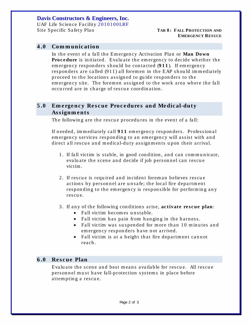
Davis Constructors & Engineers, Inc. UAF Life Science Facility 2010100LRF Site Specific Safety Plan TAB 8: FALL PROTECTION AND EMERGENCY RESUCE
Page 2 of 3
4.0 Communication In the event of a fall the Emergency Activation Plan or Man Down Procedure is initiated. Evaluate the emergency to decide whether the emergency responders should be contacted (911). If emergency responders are called (911) all foremen in the EAP should immediately proceed to the locations assigned to guide responders to the emergency site. The foremen assigned to the work area where the fall occurred are in charge of rescue coordination.
5.0 Emergency Rescue Procedures and Medical-duty Assignments The following are the rescue procedures in the event of a fall: If needed, immediately call 911 emergency responders. Professional emergency services responding to an emergency will assist with and direct all rescue and medical-duty assignments upon their arrival.
1. If fall victim is stable, in good condition, and can communicate, evaluate the scene and decide if job personnel can rescue victim.
2. If rescue is required and incident foreman believes rescue
actions by personnel are unsafe; the local fire department responding to the emergency is responsible for performing any rescue.
3. If any of the following conditions arise, activate rescue plan:
• Fall victim becomes unstable. • Fall victim has pain from hanging in the harness. • Fall victim was suspended for more than 10 minutes and
emergency responders have not arrived. • Fall victim is at a height that fire department cannot
reach.
6.0 Rescue Plan Evaluate the scene and best means available for rescue. All rescue personnel must have fall-protection systems in place before attempting a rescue.

Davis Constructors & Engineers, Inc. UAF Life Science Facility 2010100LRF Site Specific Safety Plan TAB 8: FALL PROTECTION AND EMERGENCY RESUCE
Page 3 of 3
1. Can you safely gain access with ladders, man lifts, crane basket or hoists? If yes, move equipment into place and carefully secure and rescue victim. If no, go to next option. 2. Can victim be accessed through an opening or window in the building by pulling into opening and securing? If yes, gather personnel to support operation. Secure rescue positioning device (RPD) to secure anchor point and have enough personnel at access point to connect and secure victim. If no, go to next option. 3. Is there’s an access point for lowering or raising the victim from an above elevation? If yes, gather enough personnel to raise or lower victim. Secure RPD to an anchor point above victim. Attach the RPD to the victim. If no, wait for responders. NOTE: If a victim is lowered or raised, rescuers must attach a secondary line (RPD) to victim. Responder must have approved RPD system to perform this rescue. 4. If victim is removed from arrest situation, evaluate victim’s condition to decide if medical treatment is necessary.
5. Designated personnel trained in first aid and cardiopulmonary resuscitation (CPR) are to provide medical assistance within their capacities.

Davis Constructors & Engineers, Inc. UAF Life Science Facility 2010100LRF Site Specific Safety Plan 10-322 TAB 8: FALL PROTECTION AND EMERGENCY RESCUE
Page 1 of 15
Fall Prevention and Protection
1.0 Introduction The purpose of the Fall Prevention and Protection Plan (FPPP) is to establish minimum requirements for the use of fall protection and prevention devices for employees exposed to fall hazards.
The FPPP applies to all Davis Constructors & Engineers, Inc. (Davis) projects and activities when working within the scope of our Health and Safety Policies.
2.0 Policy Anytime employees are working from an unprotected elevation of six (6) feet or more above the ground or next lower level, fall protection must be used. Working (as just described) means while traveling, stationary or at anytime exposed to a fall from a surface not protected by a standard guardrail or other approved fall prevention device.
3.0 References • 29 CFR 1926.500-.503: Fall Protection • 29 CRF 1910.66 Appendix C: Personal Fall Arrest System • ANSI Z359.1 – 1992: Fall Protection in General Industry
4.0 Definitions
Term Definition
Anchorage A secure point of attachment to which the fall protection system is ultimately connected.
Competent Person
One who is capable of identifying hazardous and dangerous conditions regarding fall protection equipment, is knowledgeable in the application and the use of the equipment, and has the authority to take prompt corrective actions.
Deceleration Device (Shock Absorber)
Any device which serves to dissipate a substantial amount of the energy during fall arrest or otherwise limits the energy imposed on the body during fall arrest.
Designated Area A fall prevention system composed of a warning line

Davis Constructors & Engineers, Inc. UAF Life Science Facility 2010100LRF Site Specific Safety Plan 10-322 TAB 8: FALL PROTECTION AND EMERGENCY RESCUE
Page 2 of 15
and stanchions erected 6′ or more from a fall hazard (unprotected roof edge).
“D” Ring An attachment point on the full-body harness for attaching a lanyard or other fall protection device.
Fall Prevention Installation of barriers or use of restraining devices physically preventing a person from being exposed to a fall hazard.
Fall Protection The use of passive equipment designed to stop and/or control the free fall once a fall is initiated.
Free Fall
Distance the D-ring travels from the onset of a fall to the time when the fall arrest system is activated (excludes deceleration distance and any system elongation).
Full-body Harness
A personal fall-protection device secured around the body, and a lanyard device attached. It’s designed to distribute fall-arresting forces primarily over the buttocks and thighs.
Lanyard A flexible strap connected to the full-body harness at one end and an anchorage or anchorage connector at the other end.
Lifeline
A flexible line for connection to an anchorage at one end to hang vertically (vertical lifeline), or for connection at both ends to stretch horizontally (horizontal lifeline) and to which other elements of a fall-arrest system are attached.
Low-sloped Roof A roof having a slope of less than or equal to 4 on 12 (vertical to horizontal).
Qualified Person
Recognized professional with an extensive knowledge of fall-prevention system who is capable in design, analysis, evaluation, and specification of fall-protection equipment.
Restraint Line A line from a fixed anchorage to which an employee is secured in such a way as to prevent the employee from reach an identified fall hazard.
Self-retracting Lifeline
A fall-protection device that eliminates slack automatically as the worker moves. These units have a braking mechanism which senses and arrests free falls.
Snap Hook A self-closing, self-locking connector used for attaching lanyard devices to the full-body harness D-ring and to the anchorage.

Davis Constructors & Engineers, Inc. UAF Life Science Facility 2010100LRF Site Specific Safety Plan 10-322 TAB 8: FALL PROTECTION AND EMERGENCY RESCUE
Page 3 of 15
5.0 Responsibilities
5.1 Site Management
Site management is (safety manager, superintendent, foreman) responsible for ensuring the overall implementation of and compliance with Davis fall-protection policies and procedures. They must be familiar with the fall-protection policy and utilize the expertise at their disposal to ensure employees are protected from fall hazards.
5.2 Site Supervision Supervisors responsible for employees performing work covered by the Davis Fall-Protection policy must:
• Continuously monitor the work to assure compliance with this procedure.
• Confirm each job is properly evaluated for fall hazards and
confirm that these hazards are properly eliminated or con-trolled.
• Ensure employees are aware of any hazards associated with
their work.
• Ensure employees receive proper training on fall hazard rec-ognition and use of fall-protection/prevention equipment.
• Ensure employees adhere to all requirements of the fall-
protection policy.
5.3 Employees Employees performing work tasks covered by this procedure must:
• Be aware of potential fall hazards associated with their work and ensure these hazards are properly addressed prior to the work beginning.
• Know the uses and limitations of fall-protection equipment.
• Inspect fall-protection equipment prior to each use and
remove any defective equipment from service.

Davis Constructors & Engineers, Inc. UAF Life Science Facility 2010100LRF Site Specific Safety Plan 10-322 TAB 8: FALL PROTECTION AND EMERGENCY RESCUE
Page 4 of 15
• Report any fall or close call to supervisor and remove from service any fall-protection equipment subjected to a fall.
5.4 Corporate Health and Safety Department The Safety Department assists site management and supervision in the implementation, training, monitoring, and documentation associated with the fall protection program. It’s also a responsibility of the Safety Department to provide the expertise and guidance necessary to help ensure employees are adequately protected from fall hazards.
5.5 Competent Persons Competent persons are responsible for ensuring:
• During mobilization and early project development, Davis project safety manager, Carl Francis will be “competent person” for Fall Protection. As the project progresses, subcontractors may designate their own “competent persons.” However, designation approval will go through the Davis Project Safety Manager.
• Thorough, documented, in-depth inspections of fall-
protection equipment was performed.
• Fall-protection equipment is used in compliance with this procedure and all manufacturers’ and regulatory requirements.
6.0 Training Employees are trained in the proper use, care, and limitations of fall-protection equipment prior to using the equipment.
At a minimum, training must address the following areas:
• Davis Fall Protection Policy and Procedures.
• Evaluating fall hazards.
• Fall prevention.
• Equipment use, care, and limitations.

Davis Constructors & Engineers, Inc. UAF Life Science Facility 2010100LRF Site Specific Safety Plan 10-322 TAB 8: FALL PROTECTION AND EMERGENCY RESCUE
Page 5 of 15
• Proper fitting and wearing of fall-protection equipment.
• Requirements and proper use of anchor points. • Inspections.
Training is documented, signed, dated by the employee and instructor, and maintained in the employee’s safety training file.
Re-training is required if a lack of proficiency is observed or when new equipment or new hazards are introduced.
7.0 Inspection and Storage
7.1 Storage Fall-protection equipment is stored in a clean dry location away from exposure to abrasive cutting tools and equipment, corrosive materials, excessive heat, and other sources of damage.
Full-body harnesses are hung by the D-ring for storage.
7.2 Inspections Prior to each use the employee/user inspects all fall-protection equipment.
Inspection consists of an evaluation of the following areas:
• Harness components:
o Stitching
o Rivets
o Buckle tabs
o Snap hooks
• “D” Rings
• Lanyards and lifelines
• Connectors

Davis Constructors & Engineers, Inc. UAF Life Science Facility 2010100LRF Site Specific Safety Plan 10-322 TAB 8: FALL PROTECTION AND EMERGENCY RESCUE
Page 6 of 15
• No tears or cuts
• No burns
• No abrasion
• No rust or corrosion
• No mildew
Defective equipment is immediately removed from service, tagged as defective, then repaired or destroyed and replaced.
7.3 In-depth Inspections Designated Competent Persons must conduct in-depth inspections of all jobsite fall-protection equipment prior to job start up and periodically (at least annually).
These in-depth fall protection inspections are documented using Appendix 1-4 or an equivalent.
The Competent Person utilizes the specific fall-protection equipment manufacturer’s inspection instructions to perform the in-depth inspections. Or, at a minimum for harnesses and lanyards, utilize the items outlined in 7.2 of this Section. Fall-protection equipment passing the in-depth inspection is documented and the documentation is kept on file at the jobsite. Care is taken not to cover with tape or markers any equipment component vital to inspection or performance. Do not cover stitching, grommets, adjusting mechanisms, labels, etc.
Some types of fall-protection equipment (such as self-retracting lifelines) require periodic recertification by the manufacturer at scheduled intervals. The Competent Person is familiar with these requirements and has recertification performed and documented.
Defective fall-protection equipment subjected to fall forces must be immediately removed from service, destroyed and replaced, or recertified by the manufacturer.
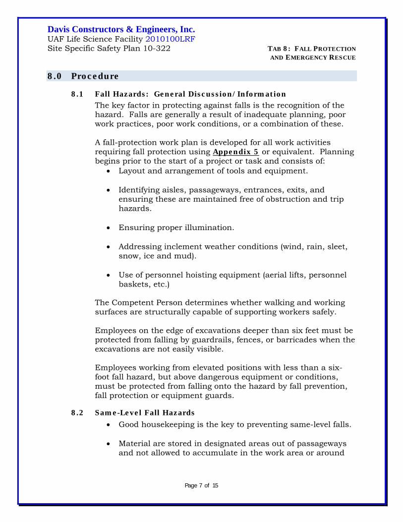
Davis Constructors & Engineers, Inc. UAF Life Science Facility 2010100LRF Site Specific Safety Plan 10-322 TAB 8: FALL PROTECTION AND EMERGENCY RESCUE
Page 7 of 15
8.0 Procedure
8.1 Fall Hazards: General Discussion/Information The key factor in protecting against falls is the recognition of the hazard. Falls are generally a result of inadequate planning, poor work practices, poor work conditions, or a combination of these.
A fall-protection work plan is developed for all work activities requiring fall protection using Appendix 5 or equivalent. Planning begins prior to the start of a project or task and consists of:
• Layout and arrangement of tools and equipment.
• Identifying aisles, passageways, entrances, exits, and ensuring these are maintained free of obstruction and trip hazards.
• Ensuring proper illumination.
• Addressing inclement weather conditions (wind, rain, sleet,
snow, ice and mud).
• Use of personnel hoisting equipment (aerial lifts, personnel baskets, etc.)
The Competent Person determines whether walking and working surfaces are structurally capable of supporting workers safely.
Employees on the edge of excavations deeper than six feet must be protected from falling by guardrails, fences, or barricades when the excavations are not easily visible.
Employees working from elevated positions with less than a six-foot fall hazard, but above dangerous equipment or conditions, must be protected from falling onto the hazard by fall prevention, fall protection or equipment guards.
8.2 Same-Level Fall Hazards • Good housekeeping is the key to preventing same-level falls.
• Material are stored in designated areas out of passageways
and not allowed to accumulate in the work area or around

Davis Constructors & Engineers, Inc. UAF Life Science Facility 2010100LRF Site Specific Safety Plan 10-322 TAB 8: FALL PROTECTION AND EMERGENCY RESCUE
Page 8 of 15
worktables, desks, threading machines, etc. causing a hazard.
• Surfaces are kept free of slipping hazards (ice, grease, oil,
chemicals, metal shavings etc.)
• Floor holes and openings are covered and secured to not create tripping hazards.
• Attempts must be made to maintain even floor surfaces.
• Electrical cords, welding leads, hoses, etc. must be elevated
or positioned so they don’t create tripping hazards.
8.3 Falls From Elevation A momentary loss of balance resulting from a slip or trip can often lead to an elevated fall. Grabbing on to something to catch oneself after balance is lost rarely succeeds. Fall prevention or protection is required to protect employees from injuries due to falls from elevation.
The objective of elevated fall “protection” is to stop or control the free fall once a fall is initiated, therefore reducing the potential for injury.
Fall hazard distance begins and is measured from the level of a workstation on which an employee must initially step and where a fall hazard exists. It ends with the greatest distance of possible continuous fall, including steps, openings, projections, roofs, and direction of fall (interior or exterior).
8.4 Fall Prevention Fall “prevention” as defined, eliminates potential for exposure to a fall. For this reason, it’s preferred over fall-protection devices and should be the first choice for eliminating exposure to fall hazards.
Examples of fall-prevention devices include:
• Guardrails: Approved guardrails are used to form a barrier
at a fall exposure. It consists of a top rail, mid-rail, and a toe board.

Davis Constructors & Engineers, Inc. UAF Life Science Facility 2010100LRF Site Specific Safety Plan 10-322 TAB 8: FALL PROTECTION AND EMERGENCY RESCUE
Page 9 of 15
• Hole Covers: Hole or floor opening covers must be strong enough to support at least twice the maximum intended load and must be installed and secured in a manner which prevents their accidental displacement or removal. They must also be clearly marked: “Danger, Hole Cover. Do Not Remove” or “Hole” or “Cover.”
• Restraint Lines: Restraint lines are designed to limit travel
so no physical hazard is reachable in any direction of movement. Restraint lines and their anchorage points must be capable of supporting at least 3,000 lbs. tensile load.
8.5 Standard Protection Standard protection against falls is the assurance of adequate guardrails, handrails, mid-rails, and toe boards are installed on all work surfaces including platforms, scaffolds, etc.
Attempts are made to either install permanent guardrails or install temporary guardrails on or around surfaces four feet above the floor level.
Scaffolds, ladders, aerial lifts, or other work platforms are used in compliance with all Davis, manufacturer, and regulatory requirements.
8.6 Fall Protection Only fall-protection equipment approved for use by a Davis Competent Person is allowed.
All fall-protection equipment is inspected prior to each use and is maintained in good working order at all times. Equipment or components found to be defective must be immediately removed from service and replaced or repaired by qualified repair personnel.
Fall-protection equipment is for fall protection use only and is not to be used for any other purpose such as positioning or hoisting.
All components of personal protection; e.g. harnesses, lanyards, anchorage, lifelines and connectors must have a minimum break strength of 5,000 pounds.
Any equipment designated for a fall-protection system, but useable for other activities (i.e. slings, choker, carabineers, etc.) must be
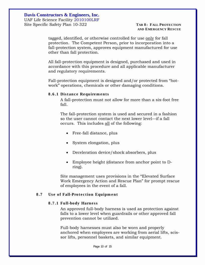
Davis Constructors & Engineers, Inc. UAF Life Science Facility 2010100LRF Site Specific Safety Plan 10-322 TAB 8: FALL PROTECTION AND EMERGENCY RESCUE
Page 10 of 15
tagged, identified, or otherwise controlled for use only for fall protection. The Competent Person, prior to incorporation into a fall-protection system, approves equipment manufactured for use other than fall protection.
All fall-protection equipment is designed, purchased and used in accordance with this procedure and all applicable manufacturer and regulatory requirements.
Fall-protection equipment is designed and/or protected from “hot-work” operations, chemicals or other damaging conditions.
8.6.1 Distance Requirements A fall-protection must not allow for more than a six-foot free fall.
The fall-protection system is used and secured in a fashion so the user cannot contact the next lower level—if a fall occurs. This includes all of the following:
• Free-fall distance, plus
• System elongation, plus
• Deceleration device/shock absorbers, plus
• Employee height (distance from anchor point to D-
ring).
Site management uses provisions in the “Elevated Surface Work Emergency Action and Rescue Plan” for prompt rescue of employees in the event of a fall.
8.7 Use of Fall-Protection Equipment
8.7.1 Full-body Harness An approved full-body harness is used as protection against falls to a lower level when guardrails or other approved fall prevention cannot be utilized.
Full-body harnesses must also be worn and properly anchored when employees are working from aerial lifts, scis-sor lifts, personnel baskets, and similar equipment.
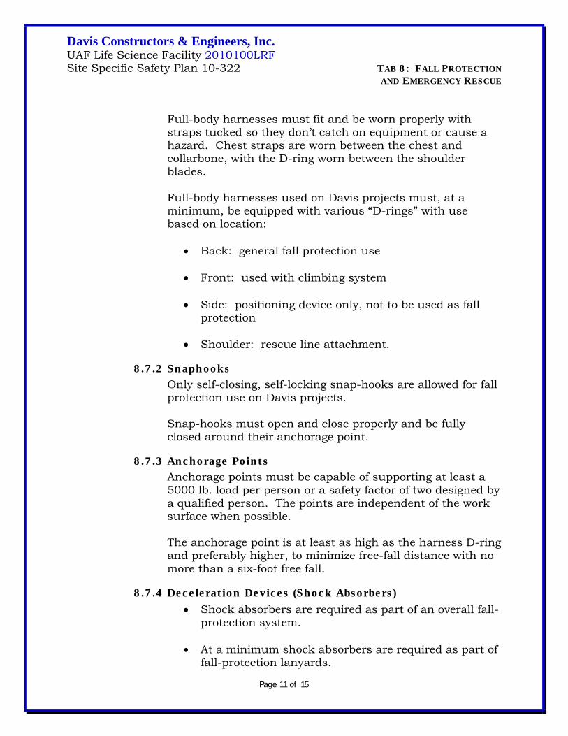
Davis Constructors & Engineers, Inc. UAF Life Science Facility 2010100LRF Site Specific Safety Plan 10-322 TAB 8: FALL PROTECTION AND EMERGENCY RESCUE
Page 11 of 15
Full-body harnesses must fit and be worn properly with straps tucked so they don’t catch on equipment or cause a hazard. Chest straps are worn between the chest and collarbone, with the D-ring worn between the shoulder blades.
Full-body harnesses used on Davis projects must, at a minimum, be equipped with various “D-rings” with use based on location:
• Back: general fall protection use
• Front: used with climbing system
• Side: positioning device only, not to be used as fall
protection
• Shoulder: rescue line attachment.
8.7.2 Snaphooks Only self-closing, self-locking snap-hooks are allowed for fall protection use on Davis projects.
Snap-hooks must open and close properly and be fully closed around their anchorage point.
8.7.3 Anchorage Points Anchorage points must be capable of supporting at least a 5000 lb. load per person or a safety factor of two designed by a qualified person. The points are independent of the work surface when possible.
The anchorage point is at least as high as the harness D-ring and preferably higher, to minimize free-fall distance with no more than a six-foot free fall.
8.7.4 Deceleration Devices (Shock Absorbers) • Shock absorbers are required as part of an overall fall-
protection system.
• At a minimum shock absorbers are required as part of fall-protection lanyards.

Davis Constructors & Engineers, Inc. UAF Life Science Facility 2010100LRF Site Specific Safety Plan 10-322 TAB 8: FALL PROTECTION AND EMERGENCY RESCUE
Page 12 of 15
8.7.5 Lanyards • The shortest length lanyard possible should always be
used. • Lanyards must have a maximum length to provide for
a free-fall distance of no more than six feet.
• Lanyards are used in conjunction with a shock absorber or shock-absorbing agent.
• Do not attach more than one person to a lanyard.
• Dual or “Y” lanyards may be required to achieve 100
percent fall protection in some work situations.
• When not in use lanyards are secured in a manner not causing tripping hazards or becoming entangled in equipment.
• Flexible steel cable lanyards are not used by personnel
performing work on or in close proximity to electrical equipment. A non-conductive lanyard must be used when near electrical equipment.
8.7.6 Retractable Devices • Retractable devices are designed to arrest fall within
two feet.
• Tag lines are used to prevent the uncontrolled retracting of these devices.
• Retractable devices are used with the person at less
than a 45-degree angle from the device to prevent the hazards of a swing fall.
• Only retractable devices bearing current manufactur-
ers certification are used.
8.7.7 Vertical Lifelines • Only one employee may use a vertical lifeline at a time.
Separate vertical lifelines are required for each employee when multiple users are required.

Davis Constructors & Engineers, Inc. UAF Life Science Facility 2010100LRF Site Specific Safety Plan 10-322 TAB 8: FALL PROTECTION AND EMERGENCY RESCUE
Page 13 of 15
• Vertical lifelines are equipped with a formed eye
termination at one end for suspension from the anchorage point and must extend below the lowest level of travel.
• The lower end is either attached to a second anchor
point or weighted down to provide stability.
• Grab devices are compatible with the type and size of rope or cable used; they remain above the shoulder of the user.
• Manufacturers specify maximum lanyard length for
use on their vertical lifelines (usually nine inches). Standard six-foot lanyards are generally not permitted.
8.7.8 Horizontal Lifelines Horizontal lifelines are either designed by a qualified person with a safety factor of at least two, or manufactured components erected by competent persons and used in compliance with all manufacturer requirements and safety factors.
8.7.9 Safety Nets Only safety nets designed by the manufacturer as fall- protection nets are used. These are installed in accordance with all manufacturer requirements, as close to work level as possible and extend outward from the surface. (See OSHA 29 CFR 1926.502 (c) for distances).
Nets may have maximum 6” by 6” openings and are either certified by a qualified person or pass a 400 lb. drop test at the following intervals: prior to use, whenever relocated, after repair, and every six months if left in place. Nets in use are inspected by a competent person at least weekly for wear, damage, and deterioration. Inspections are documented.
8.8 Work on Rooftop Equipment When performing work on equipment located on low-sloped rooftops, fall prevention or fall protection is required only if the

Davis Constructors & Engineers, Inc. UAF Life Science Facility 2010100LRF Site Specific Safety Plan 10-322 TAB 8: FALL PROTECTION AND EMERGENCY RESCUE
Page 14 of 15
work demands the employee is within six feet of the roof edge, not including access to and egress from the roof.
Fall prevention or fall protection is required at all times when performing work on equipment located on any roof other than a low-sloped roof.
8.9 Roofing Work Persons involved in roofing work are protected by either a fall-prevention or fall-protection system.
A designated area is acceptable for work on low-sloped roofs (4 on 12 vertical to horizontal) as long as employees are not required to be within six feet of the edge. If employees are within six feet of the edge, then the following is required: guardrails, restraint lines, or fall protection must be provided within six feet of the edge.
A designated area is not acceptable fall prevention for work on steep roofs (greater than 4 on 12 vertical to horizontal).
9.0 Minimum Specifications for Fall-Prevention Systems 9.1 Guardrails
Must be constructed and surfaced in a way to prevent punctures, lacerations, and snags. 9.1.1 Top Rails
• Capable of 200 lbs. with less than 3″ deflection with no permanent deformation;
• Should be 42″ high, but can be no less than 39″ high and no more than 45″ high.
9.1.2 Mid-rails • Capable of 150 lbs. with no permanent deformation. • Maximum opening of 19 inches between rails.
9.1.3 Wood Rails
• At least 2″ by 4″ top rail. • At least 1″ by 6″ mid rail. • On 8′ maximum centers. • Minimum 1500 psi construction grade lumber.

Davis Constructors & Engineers, Inc. UAF Life Science Facility 2010100LRF Site Specific Safety Plan 10-322 TAB 8: FALL PROTECTION AND EMERGENCY RESCUE
Page 15 of 15
9.1.4 Pipe Rails • 1.5″ outside diameter on 8′ maximum centers.
9.1.5 Steel Rails
• 2″ by 2″ by 3/8″ angle iron on 8′ maximum centers.
9.1.6 Wire Rope Rails • ¼″ diameter cable stretched taunt; less than 3″
deflection. • Flagged at 6′ intervals with high visibility materials.
9.2 Restraint Lines
• Capable of 3000 lb. tensile load. • Limit travel so no fall hazard is reachable in ANY direction.
9.3 Designated Areas
• Used only if low sloped area (less than or equal to 4 on 12; vertical on horizontal),
• Area must be designated six feet or more from the unprotected edge.
• Access path with warning lines to ladders, storage areas, etc.
9.3.1 Stanchions • Capable of 16 lbs. tipping strength horizontally.
9.3.2 Line/Rope
• Capable of 500 lbs. break or tensile strength between 34″ and 39″ above the work surface.
• Flagged at 6′ intervals with high visibility materials.
10.0 Fall-Protection Work and Rescue Plan A fall-protection work plan is created for each situation that fall- protection or fall-arrest systems are used. Incorporated within this plan are details of rescue procedures used in the event of an accident or fall. Jobsites will use Appendix 5 for this procedure. Appendix 1—4 FPS inspection documents
Appendix 5 FPS work plan document

Davis Constructors & Engineers, Inc. UAF Life Science Facility 2010100LRF Appendix 1 of 4 Site Specific Safety Plan 10-322 TAB 8: FALL PROTECTION
Full-Body Harness Annual Inspection Checklist
Harness Model/Name: _____________________________________________________________ Serial Number: ____________________________ Lot Number: __________________________ Date of Manufacture: ______________________ Date of Purchase: ____________________ Comments: _______________________________________________________________________ _____________________________________________________________________________ _____________________________________________________________________________
General Factors Accepted/ Rejected
Supportive Details/Comments
1. Hardware: includes D-rings, buckles, keepers and back pads. Inspect for damage, distortion, sharp edges, burrs, cracks and corrosion.
Accepted
Rejected
2. Webbing: Inspect for cuts, burns, tears, abrasions, frays, excessive soiling and discoloration.
Accepted
Rejected
3. Stitching: Inspect for pulled or cut stitches.
Accepted
Rejected
4. Labels: Inspect, making certain all labels are securely held in place and are legible.
Accepted
Rejected
5. Other: Accepted
Rejected
6. Other: Accepted
Rejected
7. Overall Disposition: Accepted
Rejected
Inspected by: __________________ Date Inspected: _______________
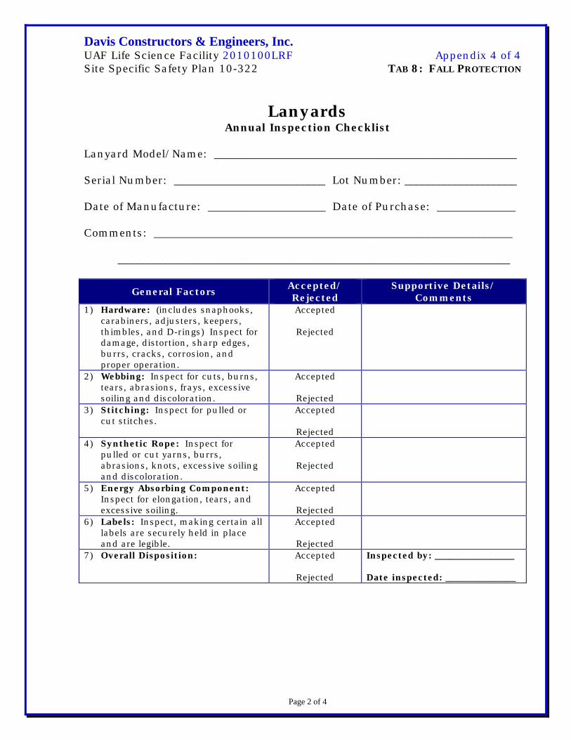
Davis Constructors & Engineers, Inc. UAF Life Science Facility 2010100LRF Appendix 4 of 4 Site Specific Safety Plan 10-322 TAB 8: FALL PROTECTION
Page 2 of 4
Lanyards Annual Inspection Checklist
Lanyard Model/Name: ______________________________________________________ Serial Number: ___________________________ Lot Number: ____________________ Date of Manufacture: _____________________ Date of Purchase: ______________ Comments: ________________________________________________________________ ______________________________________________________________________
General Factors Accepted/ Rejected
Supportive Details/ Comments
1) Hardware: (includes snaphooks, carabiners, adjusters, keepers, thimbles, and D-rings) Inspect for damage, distortion, sharp edges, burrs, cracks, corrosion, and proper operation.
Accepted
Rejected
2) Webbing: Inspect for cuts, burns, tears, abrasions, frays, excessive soiling and discoloration.
Accepted
Rejected
3) Stitching: Inspect for pulled or cut stitches.
Accepted
Rejected
4) Synthetic Rope: Inspect for pulled or cut yarns, burrs, abrasions, knots, excessive soiling and discoloration.
Accepted
Rejected
5) Energy Absorbing Component: Inspect for elongation, tears, and excessive soiling.
Accepted
Rejected
6) Labels: Inspect, making certain all labels are securely held in place and are legible.
Accepted
Rejected
7) Overall Disposition: Accepted
Rejected
Inspected by: _________________ Date inspected: _______________
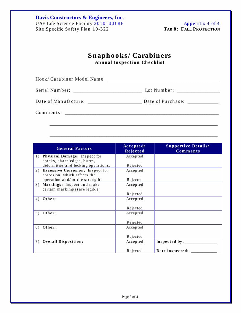
Davis Constructors & Engineers, Inc. UAF Life Science Facility 2010100LRF Appendix 4 of 4 Site Specific Safety Plan 10-322 TAB 8: FALL PROTECTION
Page 3 of 4
Snaphooks/Carabiners
Annual Inspection Checklist Hook/Carabiner Model Name: _______________________________________________ Serial Number: _____________________________ Lot Number: __________________ Date of Manufacture: _______________________ Date of Purchase: _____________ Comments: _________________________________________________________________ _______________________________________________________________________ _______________________________________________________________________
General Factors Accepted/ Rejected
Supportive Details/ Comments
1) Physical Damage: Inspect for cracks, sharp edges, burrs, deformities and locking operations.
Accepted
Rejected
2) Excessive Corrosion: Inspect for corrosion, which affects the operation and/or the strength.
Accepted
Rejected
3) Markings: Inspect and make certain marking(s) are legible.
Accepted
Rejected
4) Other: Accepted
Rejected
5) Other: Accepted
Rejected
6) Other: Accepted
Rejected
7) Overall Disposition: Accepted
Rejected
Inspected by: ________________ Date inspected: _____________

Davis Constructors & Engineers, Inc. UAF Life Science Facility 2010100LRF Appendix 4 of 4 Site Specific Safety Plan 10-322 TAB 8: FALL PROTECTION
Page 4 of 4
Self-Retracting Lanyard/Lifeline Annual Inspection Checklist
Self-retracting Lanyard/Lifeline Model Name: _________________________________ Serial Number: _________________________ Lot Number: ______________________ Date of Manufacture: ___________________ Date of Purchase: _________________ Department/Location: ______________________________________________________ Comments: _________________________________________________________________
_______________________________________________________________________
_______________________________________________________________________
General Factors Accepted/ Rejected
Supportive Details/ Comments
1) Impact Indicator: Inspect indicator for activation (rupture of red stitching, elongated indicator, etc.)
Accepted
Rejected
2) Screws/Fasteners: Inspect for damage and make certain all screws and fasteners are tight.
Accepted
Rejected
3) Housing: Inspect for distortion, cracks and other damage. Inspect anchoring loop for distortion or damage.
Accepted
Rejected
4) Laynard/Lifeline: Inspect for cuts, burns, tears, abrasion, frays, excessive soiling and discoloration. (See impact indicator section.)
Accepted
Rejected
5) Locking Action: Inspect for proper lock-up of brake mechanism.
Accepted
Rejected
6) Retraction/Extension: Inspect spring tension by pulling lanyard out fully and allowing it to retract fully (lifeline must be taut with no slack).
Accepted
Rejected
7) Hooks/Carabiners: Inspect for physical damage, corrosion, proper orientation and markings.
Accepted
Rejected
8) Labels: Inspect making certain all labels are securely held in place and are legible.
Accepted
Rejected
9) Overall Disposition: Accepted
Rejected
Inspected by: _______________ Date inspected: _____________

Davis Constructors & Engineers, Inc. UAF Life Science Facility 2010100LRF Site Specific Safety Plan 10-322 TAB 8: FALL PROTECTION AND EMERGENCY RESCUE
Page 1 of 2
FALL PROTECTION WORK PLAN-UAF LIFE SCIENCE FACILITY
Note: Employees review the requirements of this fall protection work plan prior to starting work. This plan is available at the jobsite during work activities. Also, employees are trained and instructed in accordance with 29 CFR 1926 Subpart M, Fall Protection.
Job Location Description:
1. Identify all fall hazards 1.83 m (6 ft) or more in the work area:
Leading edge Stairways Floor openings
Perimeter edge Ladders Steel erection
Scaffold erection/disassembly Through a roof
Other (describe):
2. Method of fall protection to be provided:
Fall restraint Guardrails Warning line
Fall arrest Catch platform Safety monitor
Describe:
3. Describe the correct procedure for assembly, maintenance, inspection, and disassembly of the fall protection system to be used:
4. Describe the correct procedure for handling, storage, and securing of tools and material:
5. Describe the method of providing overhead protection for workers who may be in, or pass through, the area below the work site:
Barricading Toeboards on scaffolds and floor openings
Hard hats required Warning signs
Describe:
6. Describe the method for prompt, safe removal of injured workers:
Initiate emergency response (911) Use drop lines or retraction devices
Use ladders
Utilize lift truck or personnel platform
Utilize scaffolds
Other (describe):

Davis Constructors & Engineers, Inc. UAF Life Science Facility 2010100LRF Site Specific Safety Plan 10-322 TAB 8: FALL PROTECTION AND EMERGENCY RESCUE
Page 2 of 2
FALL PROTECTION WORK PLAN-UAF LIFE SCIENCE FACILITY
7.
Describe the method used to determine the adequacy of attachment points:
Manufacturer’s data Existing engineering/design documents
Evaluation by qualified engineer Good faith assessment
8. Identify the employees working at/near a “leading edge.”
9. Identify the safety monitor(s) (if used – or N/A):
10. Justify selecting controlled access zone and/or safety monitor (if used – or N/A):
Approvals
Fall Protection Plan Completed By:
Approved By:
Responsible Supervisor Date Project Safety Date

Davis Constructors & Engineers, Inc. UAF Life Science Facility 2010100LRF Site Specific Safety Plan Tab 9: Trenching and Excavation Procedures
Page 1 of 7
Trenching and Excavation Procedures
1.0 Introduction Anytime Davis Constructors & Engineers, Inc. (Davis) or a Davis subcontractor’s employees are working near or in an excavation it’s considered a trenching and excavation activity. An excavation is a trench, hole, pit, or other circumstance where an engulfment or cave-in hazard may exist. This program provides the safety requirements for activities involving excavations in accordance with 29 CFR 1926, Subpart P – Excavations.
2.0 Scope The purpose of the Trenching and Excavation Procedures (TEP) is to establish basic criteria for safe trenching and excavation during earth moving operations. Variances in site conditions, project scope, and design features may warrant alterations to these general safety procedures. The TEP will apply to all Davis and Davis subcontractor’s projects and activities when working within the scope of our Health and Safety Policies.
3.0 Definitions Term Definition
Benching
Is a method of protecting employees from cave-ins by excavating the sides of an excavation forming one set of horizontal levels or steps usually vertical or near vertical surfaces between levels? Benching is prohibited in “C” soils.
Competent Person
A competent person is capable of identifying existing and predictable hazards in the surroundings or working conditions that are unsanitary, hazardous, or dangerous to employees, and who has authorization to take prompt corrective measures to eliminate hazards.
Excavation Any man-made cut, cavity, trench, or depression in an earth surface formed by earth removal.
Hazardous Atmosphere
An atmosphere that by reason of being explosive, flammable, poisonous, corrosive, oxidizing, irritating, oxygen deficient, toxic or otherwise harmful, may cause death, illness, or injury.
Protective Systems A method of protecting employees from cave-ins from material

Davis Constructors & Engineers, Inc. UAF Life Science Facility 2010100LRF Site Specific Safety Plan Tab 9: Trenching and Excavation Procedures
Page 2 of 7
that could fall or roll from an excavation or from the collapse of adjacent structures. Protective systems include support systems, sloping and benching systems, shield systems, and other systems providing the necessary protection.
Sloping
A method of protecting employees from cave-ins by excavation to form sides of an excavation inclined away from the excavation preventing cave-ins. The angle of incline required to prevent a cave-in varies with differences in factors as well as the soil type, environmental conditions of exposure, and application of surcharge loads.
Support System A structure such as underpinning, bracing, or shoring, providing support to an adjacent structure, underground installation, or the sides of an excavation.
Trench
A narrow excavation made below the surface of the ground. In general the depth is greater than the width, but the width of a trench measured at the bottom is not greater than 15′. If forms or other structures are installed or constructed in an excavation so as to reduce the dimension measured from the forms or structure to the side of the excavation of 15′ or less, the excavation is also considered to be a trench.
4.0 Responsibilities
4.1 Competent Person The competent person(s) is responsible for:
• Day-to-day oversight of open excavations and trenches.
• Conducting soil classifications.
• Selection of protective systems.
• Conducting daily inspections of open excavations and trenches.
• Providing the Safety Manager with all required
documentation on a daily basis.
4.2 Line Management The Safety Manager, in conjunction with the Superintendent is responsible for:
• Ensuring compliance with this procedure.

Davis Constructors & Engineers, Inc. UAF Life Science Facility 2010100LRF Site Specific Safety Plan Tab 9: Trenching and Excavation Procedures
Page 3 of 7
• Providing the necessary resources for compliance with this procedure.
• Designating competent personnel.
4.3 Project Safety Manager The Project Safety Manager is responsible for:
• Conducting review of open trenches and excavations. • Maintaining required records.
5.0 Procedures The following sections provide general requirements governing activities in and around open excavations and trenches as well as the requirements for the selection and use of protective systems. The requirements are presented in Section 5.1 and 5.2 respectively.
5.1 Designation of Competent Person Prior to starting any excavation work the superintendent designates a competent person to fulfill the requirements of this procedure. Until the civil subcontractor designates a competent person for his activities, Carl Francis Project Safety Manager is designated for this position.
5.2 General Requirements • Surfaces surrounding open trenches and excavations
have all surface hazards removed.
• All utilities are located and cleared prior to initiating digging, public or facility utility groups are utilized where possible for this purpose. In the absence of either, the subcontractor specifies the procedure to use to clear utilities in consultation with the Davis Superintendent and Project Safety Manager. When the excavation is open utilities are supported and protected from damage. Clearance and support methods are documented on the daily inspection checklist.
• Where structural ramps are used for egress, they’re
installed in accordance with 1926.651 (c) (1).

Davis Constructors & Engineers, Inc. UAF Life Science Facility 2010100LRF Site Specific Safety Plan Tab 9: Trenching and Excavation Procedures
Page 4 of 7
• Stairways, ladders, or ramps are provided as means of egress in all trenches 4 feet or more in depth. Travel distance is no more than 50 feet between means of exit, thus limiting maximum travel 25 feet.
• Employees shall wear traffic vests.
• No employee is permitted under loads being lifted or
under loads being unloaded from vehicles.
• When vehicles and machinery are operating adjacent to excavations, warning systems such as stop logs or barricades are used to prevent vehicles from entering the excavation or trench.
• Scaling or barricades are used to prevent rock and soils
from falling on employees.
• Excavated and loose material is kept at least 3 feet from the edge of excavations.
• Walkways or bridges with standard railing are provided at
points employees cross over excavations or trenches.
• Barriers are provided to prevent personnel from inadvertently falling into an excavation.
5.3 Hazardous Atmospheres Where atmospheres containing less than 19.5 percent oxygen or other types of hazardous atmospheres may exist the following requirements are implemented:
• Atmospheric testing is done prior to employees entering excavations 4 feet or greater in depth.
• Testing methods are listed on the daily inspection
checklist and results documented daily in field logs.
• Control measures such as ventilation and PPE are used to control employee exposure to hazardous atmospheres below published exposure limits.

Davis Constructors & Engineers, Inc. UAF Life Science Facility 2010100LRF Site Specific Safety Plan Tab 9: Trenching and Excavation Procedures
Page 5 of 7
• Ventilation is used to control flammable and combustible vapors to below 10 percent of their lower explosive limit.
• Testing is repeated as often as necessary to ensure safe
levels of airborne contaminants.
• Emergency equipment is provided and present when the potential for a hazardous atmosphere exists. This equipment includes (but, is not limited to) an emergency breathing apparatus, harnesses, lifelines, and basket stretchers. Required equipment is listed on the daily inspection checklist and reviewed daily.
5.4 Protection From Water Hazard When water collects in excavations and trenches the following is required:
• Employees do not work in excavations in which water has, or is, accumulating without the use of additional protection such as special support systems or water removal.
• Water removal is monitored by a competent person.
• Barriers such as ditches and dikes are used to divert
runoff from excavations and trenches.
• Trenches are re-inspected prior to re-entry after water accumulation due to heavy rainfall or seepage.
5.5 Stability of Adjacent Structures When excavating or trenching near an adjacent structure the following practices are implemented:
• Support systems such as shoring, bracing, or underpin-ning are provided when the stability of buildings, walls, or other such structures is endangered by excavation.
• Excavations at bases or footings of foundations are
prohibited unless: o support systems are used, o the excavation is in stable rock,

Davis Constructors & Engineers, Inc. UAF Life Science Facility 2010100LRF Site Specific Safety Plan Tab 9: Trenching and Excavation Procedures
Page 6 of 7
o a professional engineer (PE) determines the structure sufficiently removed from the site does not pose a hazard,
o or the PE determines the excavation does not pose a hazard to employees due to the structure.
• Support systems are used when it’s necessary to
undermine sidewalks, pavements, and appurtenant structures.
• Surcharge load sources and adjacent encumbrances are
listed with their evaluation date on the daily inspection checklist.
5.6 Daily Inspections Inspections are performed daily on all excavations, adjacent areas, and protective systems before personnel enter the trench. The checklist provided in Appendix 1 or equivalent is used.
5.7 Soil Classifications To perform soil classifications, the competent person uses a thumb test, pocket penetrometer, or shear vane to determine the unconfined compressive strength of the soils being excavated. In soils with changing properties (i.e. one soil type mixed with another within a given area) several tests may be necessary. When different soil types are present, the overall classification is that of the type with the loosest unconfined compressive strength. Classifications result in a soil rating of Stable Rock, Type A, Type B, or Type C in daily inspection checklist. The soil analysis checklist provided in Appendix 2 or equivalent is used for soil classifications.
5.8 Sloping and Benching All sloping and benching is done in accordance with 29CFR 1926.652, Appendix B. Selection of the sloping method and evaluation of the surface surcharge loads is made by a competent person familiar with the requirements of 29CFR 1926.652, Appendix B. Sloping and benching methods and specifications are listed on the daily inspection checklist.

Davis Constructors & Engineers, Inc. UAF Life Science Facility 2010100LRF Site Specific Safety Plan Tab 9: Trenching and Excavation Procedures
Page 7 of 7
5.9 Protective Systems Protective systems are required on all excavations over 4 feet in depth or in excavations less than 4 feet when examination of the ground by a competent person reveals conditions may result in cave-ins.
6.0 Training Competent person has an adequate combination of experience and training to classify soil types and select protective systems as outlined in 29 CFR 1926.652. Training and experience pertaining to qualification as a competent person is documented and include the following:
• General safety practices related to working in or near open
excavations.
• Inspection requirements and techniques.
• Classifications of soils in accordance with 29 CFR 1926.652.
• Uses, limitations, and specifications of protective systems in accordance with 29 CFR 1926.652.
7.0 References OSHA (U.S. Department of Labor, Occupational Safety and Health Administration) 29 CFR 1926, subpart P, Excavations.
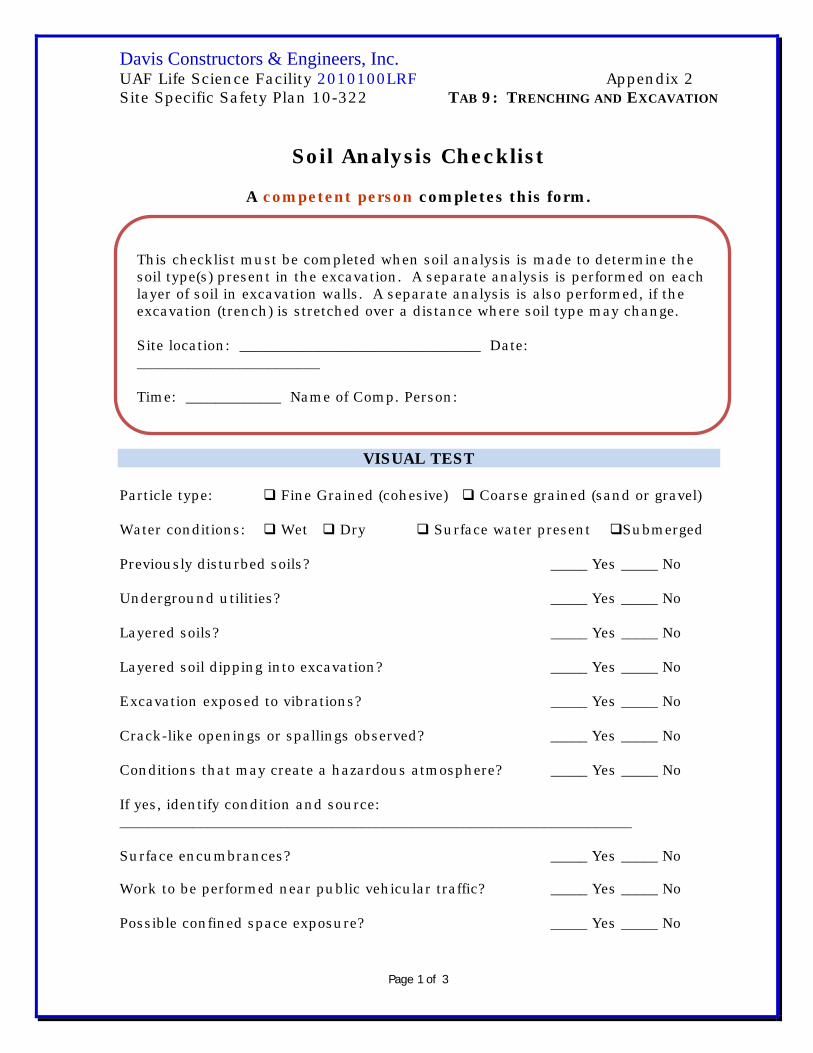
Davis Constructors & Engineers, Inc. UAF Life Science Facility 2010100LRF Appendix 2 Site Specific Safety Plan 10-322 TAB 9: TRENCHING AND EXCAVATION
Page 1 of 3
Soil Analysis Checklist
A competent person completes this form.
VISUAL TEST Particle type: Fine Grained (cohesive) Coarse grained (sand or gravel) Water conditions: Wet Dry Surface water present Submerged Previously disturbed soils? _____ Yes _____ No Underground utilities? _____ Yes _____ No Layered soils? _____ Yes _____ No Layered soil dipping into excavation? _____ Yes _____ No Excavation exposed to vibrations? _____ Yes _____ No Crack-like openings or spallings observed? _____ Yes _____ No Conditions that may create a hazardous atmosphere? _____ Yes _____ No If yes, identify condition and source: ______________________________________________________________________ Surface encumbrances? _____ Yes _____ No Work to be performed near public vehicular traffic? _____ Yes _____ No Possible confined space exposure? _____ Yes _____ No
This checklist must be completed when soil analysis is made to determine the soil type(s) present in the excavation. A separate analysis is performed on each layer of soil in excavation walls. A separate analysis is also performed, if the excavation (trench) is stretched over a distance where soil type may change. Site location: _________________________________ Date: _________________________ Time: _____________ Name of Comp. Person:

Davis Constructors & Engineers, Inc. UAF Life Science Facility 2010100LRF Appendix 2 Site Specific Safety Plan 10-322 TAB 9: TRENCHING AND EXCAVATION
Page 2 of 3
MANUAL TEST Plasticity: Cohesive Non-cohesive Dry Strength: Granular (crumbles easily) Cohesive (broken with difficulty) NOTE: The following unconfined compressive strength tests should be performed on undisturbed soil.
THUMB TEST (Used to estimate unconfined compressive strength of cohesive soil) Test Performed: _____ Yes _____ No _____ Type A (soil indented by thumb with very great effort) _____ Type B (soil indented by thumb with some effort) _____ Type C (soil with unconfined compressive strength of 1.5 tsf or less). Soil is submerged, seeping water, subject to surface water, runoff, exposed to wetting.
WET SHAKING TEST (Used to determine percentage of granular and cohesive materials) Compare _____ to soil textural classification chart to determine soil type. Test performed: _____ Yes _____ No
Type A (clay, silty clay, sandy clay, clay loam, and in some cases silty clay, loam and silty clay loam)
Type B (angular gravel [similar to crushed rock], silt, silt loam, sandy loam, and in some cases clay loam and sandy clay loam)
Type C (granular soil including gravel, sand and loamy sand) _____ % granular _____ % cohesive _____ % silt

Davis Constructors & Engineers, Inc. UAF Life Science Facility 2010100LRF Appendix 2 Site Specific Safety Plan 10-322 TAB 9: TRENCHING AND EXCAVATION
Page 3 of 3
NOTE about Type A: No soil is Type “A” if soil is fissured, subject to vibration, previously disturbed, layered, dipping into the excavation on a slope of 4H:1V. Soil Classification:
Type A
Type B
Type C Selection of Protective System:
Sloping, Specify angle: _____
Timber Shoring
Aluminum Hydraulic Shoring NOTE: Although Federal OSHA accepts the above tests in most cases, some states do not. Check Alaska’s safety requirements for trenching regulations.
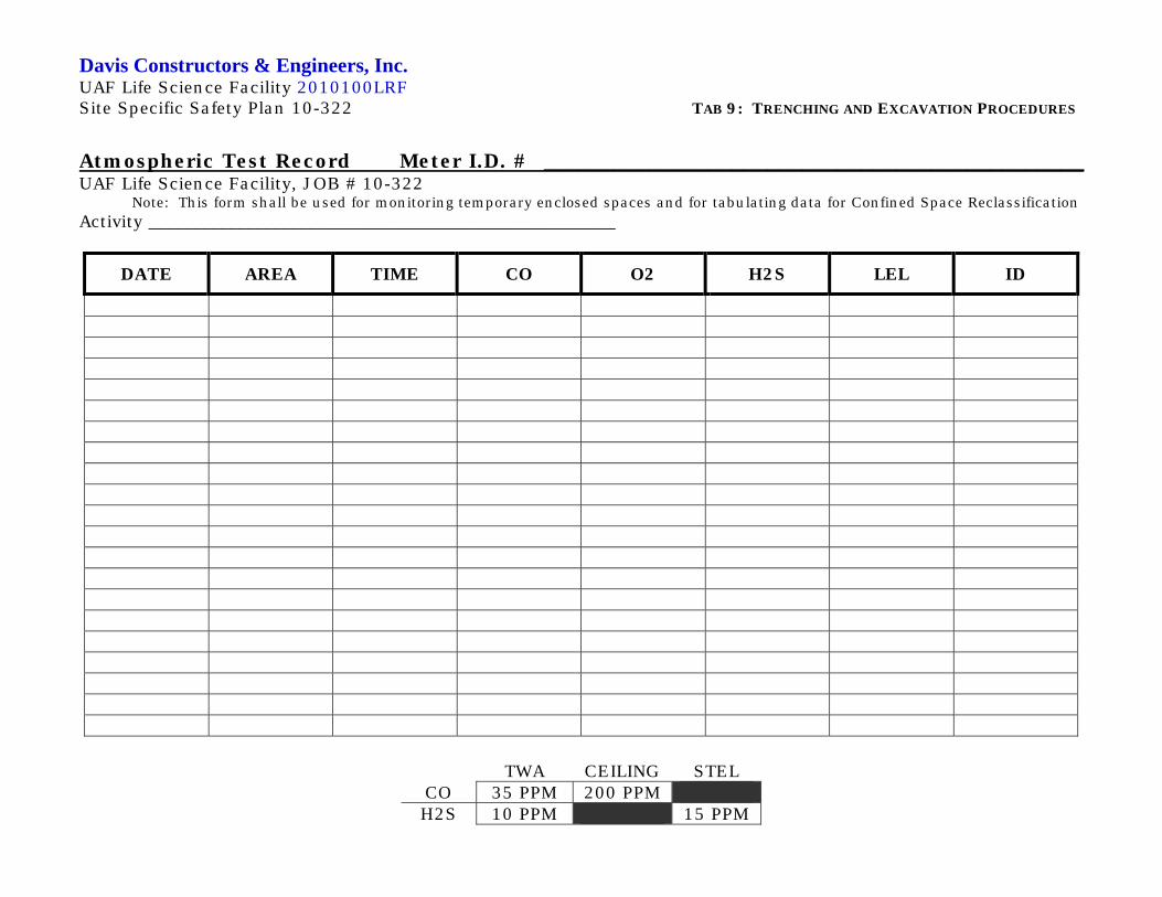
Davis Constructors & Engineers, Inc. UAF Life Science Facility 2010100LRF Site Specific Safety Plan 10-322 TAB 9: TRENCHING AND EXCAVATION PROCEDURES
TWA CEILING STEL CO 35 PPM 200 PPM H2S 10 PPM 15 PPM
Atmospheric Test Record Meter I.D. # ______________________________________________ UAF Life Science Facility, JOB # 10-322
Note: This form shall be used for monitoring temporary enclosed spaces and for tabulating data for Confined Space Reclassification Activity _____________________________________________________
DATE AREA TIME CO O2 H2S LEL ID

Davis Constructors & Engineers, Inc. UAF Life Science Facility 2010100LRF Site Specific Safety Plan 10-322 TAB 10: CONFINED SPACE PROCEDURES
Page 1 of 4
Confined Space Procedures
1.0 Introduction Davis Constructors & Engineers, Inc. (Davis) established control procedures to protect all personnel entering a permit-required confined space (PRCS) and to comply with applicable regulatory standards. (29CFR 1910.146) These include planning, general precautions, evaluations of hazards, ventilation requirements, personal protection and isolation responsibilities.
2.0 Definitions
Term Definition
Confined Space Any space with a limited means of entry and egress, is large enough to enter and perform work, and is not intended for human occupancy or, has unfavorable natural ventilation.
Non-Permit Required Con-
fined Space
Is a confined space not containing or (with respect to atmospheric hazards) having the potential to contain any hazard capable of causing death or serious physical harm. Design or historical records are used to docu-ment no potential hazard(s) exists.
Permit-Required Confined Space
(PRCS) A confined space with a known or potentially hazardous atmosphere, is subject to accumulation of toxic or flammable contaminants, has an oxygen-deficient atmosphere, engulfs hazards, inwardly sloping walls, dangerously sloping floors, or has any other serious safety hazard.
Flammable Atmospheres
Flammable atmospheres are atmospheres with readings in excess of 10% of the lower explosive limit (LEL) for the chemical sampled.
Oxygen-Deficient Atmospheres
Oxygen-deficient atmospheres are deemed to exist if the atmospheres contain less than 19.5% oxygen by volume.
Oxygen-Enriched
Atmospheres
Oxygen enriched atmospheres are deemed to exist if the atmospheres contain more than 23% oxygen by volume.
Toxic Atmos-pheres
Toxic atmospheres are atmospheres having concentra-tion of airborne chemicals in excess of state or federal exposure limits.

Davis Constructors & Engineers, Inc. UAF Life Science Facility 2010100LRF Site Specific Safety Plan 10-322 TAB 10: CONFINED SPACE PROCEDURES
Page 2 of 4
3.0 Responsibilities
3.1 Employer It’s the employer’s responsibility to train its supervisors and crafts
for the hazards of working in a confined space and the procedures that must be followed for such work. The employer’s procedures address general precautions, evaluation of hazards, including ventilation requirements, personal protection requirements, etc.
3.2 Employee It’s the employee’s responsibility to follow the confined-space entry
programs and procedures to the fullest extent possible and report any deviations from this policy to the entry supervisor, project safety manager, or foreman immediately.
3.3 Project Safety Manager/Competent Person It’s the project safety manager and Competent Person responsibility to ensure a confined space is safe to work in. Personnel are not sent into a confined space, if any questions exist about the safety of that work space.
3.4 Superintendent/Foreman The superintendent uses an employee selection process ensuring employees are physically able to perform the job. This means they’re able to gain entry and egress and able to work with respiratory and other required equipment.
4.0 Training Through safety meetings and orientations employees receive periodic training on confined-space work. It includes hazards they’re likely to encounter, permitting procedures, personal protective equipment requirements, purpose and function of testing, monitoring and life supporting system(s), and rescue procedures (including drills). It must be clearly understood employees are not allowed to enter any confined space without having received confined-space entry training with documentation of training/testing on file in the jobsite office.

Davis Constructors & Engineers, Inc. UAF Life Science Facility 2010100LRF Site Specific Safety Plan 10-322 TAB 10: CONFINED SPACE PROCEDURES
Page 3 of 4
5.0 PRCS Pre-entry
5.1 Air Monitoring Where work is performed by Davis the project safety manager ensures confined spaces and vessels are steamed, flushed, or purged of flammable or toxic atmospheres prior to entry. Once safe entry is determined, the confined space is tagged. However, before employees are allowed to enter any confined space, backup monitoring must be completed by the project safety manager who then issues a confined-space entry permit (Appendix I) and conducts periodic monitoring throughout the duration of the confined-space entry. The confined-space entry permit is displayed at the entrance as long as workers are in the space. Confined-space entries that may include welding, cutting, respiratory protection, or have the possibility of an IDLH (Immediate Dangerous to Life or Health) atmosphere include continual full-time monitoring for percent of oxygen, combustibles, and toxic fumes.
5.2 PRCS Checklist Before entry into confined space is granted a Davis Entry Checklist (Appendix I) is completed in detail by the foreman or competent designee requesting entry and reviewed by the safety officer. In addition, the Emergency Planning Procedures (Appendix I) is reviewed by all employees involved in the confined space work including the attendant.
5.3 PRCS Attendant All personnel working in a confined space are advised by their PRCS attendant or foreman to immediately evacuate if any unusual or noxious odors develop within the confined space. A trained PRCS attendant is posted outside the limits of the confined space at all times employees are working inside. At no time does the attendant enter the confined space. If trouble is observed, it’s the attendant’s responsibility to notify the proper personnel. If the work is in a remote area or the employees are not constantly within observation or hearing range, the attendant is equipped with a two-way radio or cell. phone to summon help, if necessary. In addition, the attendant has available and ready for use an emergency self-contained breathing apparatus (SCBA).

Davis Constructors & Engineers, Inc. UAF Life Science Facility 2010100LRF Site Specific Safety Plan 10-322 TAB 10: CONFINED SPACE PROCEDURES
Page 4 of 4
6.0 Chemicals and Compressed Gases The use of any chemicals in a confined space requires the approval of the project safety manager or project superintendent prior to their use. A review of the MSDS is a minimum requirement prior to the approval of use. The use of compressed gas cylinders is allowed inside the confined space only with the special permission from the project safety manager.
7.0 Personal Protective Equipment Suitable protective equipment is worn when entering a confined space. Although the equipment can vary from job to job it may include respiratory equipment, acid or caustic resistant apparel, suitable gloves, eye and face protection, head protection, hearing protection, and foot protection.
8.0 Rescue Fire department dispatch is contacted prior to entry into a PRCS. The fire department dispatch is notified of the location of entry, the number of workers entering and any other information they require. Entry proceeds once the dispatch verified the entry. The attendant calls the dispatch every hour to update the status of the entry. When entry is complete the dispatch is notified.
If there’s an emergency requiring rescue services, the attendant calls the dispatch directly or calls 911. If the possibility exists of a highly, flammable, or oxygen-deficient atmosphere or could develop, workers wear a safety harness or wrist straps with lifeline attached. A method of rescue such as a tripod is provided.

Davis Constructors & Engineers, Inc. UAF Life Science Facility 2010100LRF Site Specific Safety Plan 10-322 Appendix 1 TAB 10: CONFINED SPACE PROCEDURES
Page 1 of 1
Confined Spaces Emergency Planning and Procedures
Overview:
• Anticipated hazards • Type of incidents • Response plan • Training of personnel (confined space workers, attendants, and
rescuers) Essentials of the Plan:
• Who is responsible for rescue operation? • Who to call off-premises and when? • Communication: Worker to Attendant – Attendant to Rescuers • Location and type of rescue equipment • Special training on rescue equipment • Lighting (Location and type) • Medical facilities and personnel • Power ventilation and air compressors • Need for specially trained staff (HazMat, radiation, fire). • Permit plan in use – special information shown (physical structure,
chemicals in use, nature of work, etc) The Six Essentials of Rescue:
• Rescue from outside if possible • Enter to rescue only after help arrives • Always assume presence of an IDLH atmosphere • Only use SCBA or SAR (P/D) with escape bottle • Never use same air (or atmosphere) as confined space workers • Safety harnesses and lifelines in addition to PPE
Rescue Personnel Training:
• Hands-on, repetitive, on-site • Torches, saws, ventilation principles, fire fighting, first aid, CPR,
decontamination, spill containment, etc. All confined space rescue and other emergencies will be provided by the UAF Fire and Police Departments. At this time an agreement has been reached but written documentation has not occurred.

Davis Constructors & Engineers, Inc. UAF Life Science Facility 2010100LRF Appendix 2 Site Specific Safety Plan 10-322 TAB 10: CONFINED SPACE PROCEDURES
Page 1 of 1
PRCS Entry Checklist All applicable items will be ‘YES’ or ‘N/A’ for the permit to be valid. Yes No N/A 1. Procedure provided, reviewed, and enforced?
a. All job procedures reviewed, understood, and training completed?
b. Person on site at all times to enforce all procedures? c. Material Safety Data Sheets (MSDS) reviewed? 2. Welding, cutting, open flame present, welding permit approved and
posted?
3. Confined space isolated?
a. Lockout/Tagout procedure followed? b. Power sources off and locked out? c. Electrical hazards isolated, removed, and tagged? d. Rotating equipment locked out, removed, or disconnected? e. Lines carrying materials to and from confined space blanked
off, section removed or locked by two valves and drained? Drain valve locked open and tagged?
f. Contents removed and flushed? 4. Confined space atmosphere prepared and monitored?
a. Purged? b. Flanges and access doors removed or manholes opened? c. Continuous ventilation provided? d. Oxygen level maintained over 19.5% but less than 23%? e. Air monitoring equipment provided? 5. PPE provided and specific instructions giving for its use?
a. Air lines, SCBA or other approved respirators provided? b. Safety harnesses with D-ring and life line provided? c. Head, hearing, hand, foot and body protection provided? d. Lighting equipment of approved type provided and grounded? e. Fire extinguishers readily available? f. Walking/working surfaces protected from slippage? 6. Attendant standing outside of space trained and ready to respond to
emergencies?
a. Rescue equipment provided at confined space? b. Emergency alarms or communications available? Supervisor Date
Supervisor Date
Supervisor Date

Davis Constructors & Engineers, Inc. UAF Life Science Facility 2010100LRF Site Specific Safety Plan 10-322 Appendix 3 TAB 10: CONFINED SPACE PROCEDURES
Page 1 of 2
Confined-Space Entry Permit 1. Location of Space
2. Description of Space
3. Employee authorizing entry 4. Date
5. Purpose of authorization
6. Entry authorized from to 7. Date
8. Authorized entrants
9. Authorized attendants(s)
Space Hazards and Controls
1. Asphyxiating: Oxygen deficiency [ ] Chemical [ ] Engulfment [ ]
2. Flammable/Explosive: Dust [ ] Chemical (specify)
3. Toxic: Chemical (specify)
4. Unauthorized Activation: Mechanical Electrical
5. The confined space shall be isolated or potential hazards controlled by: Depressurization [ ] Purging and cleaning pipe [ ] Ventilation [ ]
Lockout/tagout [ ] Blanking/capping pipe [ ] Other (specify) [ ]
6. Rescue services/equipment are available: Onsite [ ] Outside [ ]
7. Communications equipment procedures to be used:
8. The following personal protective equipment have been assigned to, and shall be worn by entrants:
9. Hot work [ may | shall not ] be conducted in this space. If hot work is permitted, the following
controls shall be utilized:

Davis Constructors & Engineers, Inc. UAF Life Science Facility 2010100LRF Site Specific Safety Plan 10-322 Appendix 3 TAB 10: CONFINED SPACE PROCEDURES
Page 2 of 2
Testing and Monitoring
1. The space has an oxygen content of and is [ safe | unsafe ].
2. The space has been monitored and contains the following concentrations of toxic hazards:
Carbon Monoxide Hydrogen Sulfide Methane
Other (specify)
3. The space has been tested and contains the following percentages of lower flammable limit of flammable/explosive chemicals (specify):
4. Monitoring will be conducted: continuously[ ]or at intervals.
Authorization: All actions and conditions necessary for safe entry to, work in, and exit from the confined space have been performed. Entry is permitted on the date and time, and for the duration, specified above.
Time (Signature of individual authorizing entry)
Cancellation: All entrants have exited the confined spaces and this permit is cancelled.
Time (Signature of individual canceling entry)

Davis Constructors & Engineers, Inc. UAF Life Science Facility 2010100LRF Appendix 4 Site Specific Safety Plan 10-322 TAB 10: CONFINED SPACE PROCEDURES
TWA CEILING STEL CO 35 PPM 200 PPM H2S 10 PPM 15 PPM
Atmospheric Test Record Meter I.D. # __________________________________ UAF LIFE SCIENCE FACILITY, JOB # 10-322
Note: This form shall be used for monitoring temporary enclosed spaces and for tabulating data for Confined Space Reclassification. Activity _____________________________________________________
DATE AREA TIME CO O2 H2S LEL ID
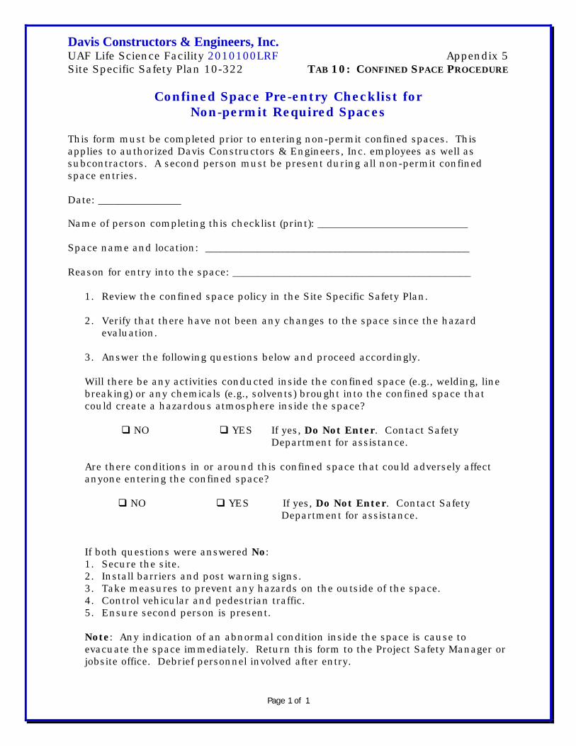
Davis Constructors & Engineers, Inc. UAF Life Science Facility 2010100LRF Appendix 5 Site Specific Safety Plan 10-322 TAB 10: CONFINED SPACE PROCEDURE
Page 1 of 1
Confined Space Pre-entry Checklist for Non-permit Required Spaces
This form must be completed prior to entering non-permit confined spaces. This applies to authorized Davis Constructors & Engineers, Inc. employees as well as subcontractors. A second person must be present during all non-permit confined space entries. Date: ________________
Name of person completing this checklist (print): _____________________________ Space name and location: ___________________________________________________ Reason for entry into the space: ______________________________________________
1. Review the confined space policy in the Site Specific Safety Plan.
2. Verify that there have not been any changes to the space since the hazard evaluation.
3. Answer the following questions below and proceed accordingly. Will there be any activities conducted inside the confined space (e.g., welding, line breaking) or any chemicals (e.g., solvents) brought into the confined space that could create a hazardous atmosphere inside the space? NO YES If yes, Do Not Enter. Contact Safety Department for assistance. Are there conditions in or around this confined space that could adversely affect anyone entering the confined space? NO YES If yes, Do Not Enter. Contact Safety Department for assistance. If both questions were answered No: 1. Secure the site. 2. Install barriers and post warning signs. 3. Take measures to prevent any hazards on the outside of the space. 4. Control vehicular and pedestrian traffic. 5. Ensure second person is present.
Note: Any indication of an abnormal condition inside the space is cause to evacuate the space immediately. Return this form to the Project Safety Manager or jobsite office. Debrief personnel involved after entry.

Davis Constructors & Engineers, Inc. UAF Life Science Facility 2010100LRF Site Specific Safety Plan 10-322 TAB 11: LOCKOUT/TAGOUT PROGRAM
Page 1 of 2
Lockout/Tagout Program Purpose: Isolating hazardous energy to prevent sudden and unexpected energization of machines, equipment and processes is an important component in our safety and health program. Authorization and affected employees participate in the lockout/tagout program. All other employees will be trained in lockout awareness. Scope: This program applies to all project personnel engaged in activities where the release of hazardous energy is a possibility. Only lockout/tagout (LO/TO) procedures will be allowed. Tagout procedures are prohibited and are not used. LO/TO procedures are used whenever machines, equipment or processes are being serviced, maintained, or repaired. LO/TO procedures must also be used when an employee bypasses a machine safeguard to service or repair a machine. When LO/TO provisions cannot be met, such as in hot-tap operations, full protection of employees through the use of additional mechanisms. Procedure: This procedure established the minimum level of protection and ensures that all machinery or equipment is isolated from all sources of energy until the work I complete. Responsibility: Appropriate employees are instructed in the safety significance of the LO/TO procedure. Each new or transferred employee and other employees (whose work operations are or may be in the area) are instructed in the use and purpose of the procedure. Preparation for LO/TO: Conduct and document a survey of all isolating devices for the equipment to be locked and tagged out. More than one energy source may be involved. Sequence:
1. Notify all affected employees that a LO/TO system is going to be used and the reason. The authorized employee knows the type and magnitude

Davis Constructors & Engineers, Inc. UAF Life Science Facility 2010100LRF Site Specific Safety Plan 10-322 TAB 11: LOCKOUT/TAGOUT PROGRAM
Page 2 of 2
of energy the machine or equipment uses and understands the hazards of the machine or equipment.
2. If the machine or equipment is operating, shut it down using the normal procedure.
3. Operate the switch, valve or other energy-isolating device so that the equipment is isolated from its energy source. Stored energy sources such as springs, flywheels, hydraulic systems, steam, air pressure, etc. must be dissipated by bleeding, blocking, jacking, etc. Lockout and tagout the energy isolating devices with assigned individual locks and tags.
4. After reviewing the procedure, push or operate the start-up device (switch, valve, etc.) to make certain the equipment will not operate. Remember to restore the controls to neutral or off after the test.
5. The equipment is now locked and tagged out. Restoring Machines or Equipment to Normal Production Operations:
1. After the servicing and/or maintenance are complete and equipment is ready for normal operations, check the area around the machines or equipment to ensure that no one is exposed.
2. After all tools are removed from the machine or equipment, guards are reinstalled, and employees are in the clear, remove all LO/TO devices. Operate the energy-isolating devices to restore energy to the equipment.
Procedure Involving More Than One Person: In the preceding steps, if more than one person is required to LO/TO the equipment, each person places his or her own personal LO/TO device on the energy isolating device. When an energy isolating device cannot accept multiple locks or tags, a multiple lockout device must be used. As each person no longer needs to maintain his or her lockout protection that person will remove his or her lock from the multiple lockout device. All equipment is locked and tagged out to protect against accidental or inadvertent operation when such operation could cause injury to personnel. Do not attempt to operate any switch, valve, or other energy-isolating device where it’s locked or tagged out.

Davis Constructors & Engineers, Inc. UAF Life Science Facility 2010100LRF Site Specific Safety Plan TAB 12: FORKLIFT PROCEDURES AND TRAINING
Page 1 of 14
Forklift Procedures and Training
1.0 Introduction Material handling is a significant safety concern. Numerous possibilities for personal injury and property damage exist when moving products and materials, if proper procedures and cautions are not used. This information applies to all forklifts, powered-industrial trucks, hoists, and lifting gear. This information is for training prospective industrial-truck operators and for providing the basis for refresher and annual retraining. OSHA reference for Powered-Industrial Trucks is 1910.178.
2.0 Responsibilities
2.1 Management • Provide adequate training in safe operation of all
equipment used to move or access materials.
• Provide safe equipment to operate.
• Implement an “Out of Service” program for damaged equipment.
• Prohibit modification of equipment except those
authorized in writing by the equipment manufacturer.
• Establish safe operating rules and procedures.
2.2 Superintendents • Monitor safe operations of material-handling equipment.
• Ensure all equipment is safety checked daily.
• Tag “Out of Service” any damaged equipment.
• Ensure all subcontractors using our equipment are
trained (show documentation) and evaluated by Davis Constructors and Engineers, Inc. (Davis) personnel.
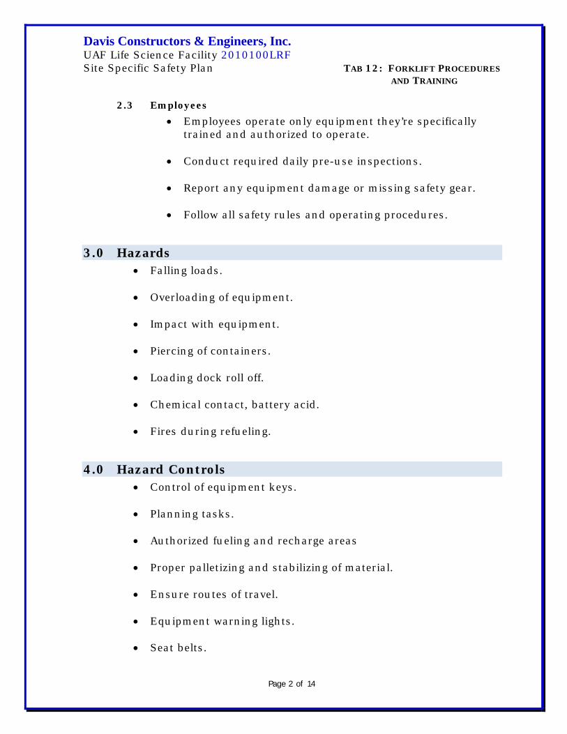
Davis Constructors & Engineers, Inc. UAF Life Science Facility 2010100LRF Site Specific Safety Plan TAB 12: FORKLIFT PROCEDURES AND TRAINING
Page 2 of 14
2.3 Employees • Employees operate only equipment they’re specifically
trained and authorized to operate.
• Conduct required daily pre-use inspections.
• Report any equipment damage or missing safety gear.
• Follow all safety rules and operating procedures.
3.0 Hazards • Falling loads. • Overloading of equipment.
• Impact with equipment.
• Piercing of containers.
• Loading dock roll off.
• Chemical contact, battery acid.
• Fires during refueling.
4.0 Hazard Controls • Control of equipment keys. • Planning tasks. • Authorized fueling and recharge areas
• Proper palletizing and stabilizing of material.
• Ensure routes of travel.
• Equipment warning lights.
• Seat belts.

Davis Constructors & Engineers, Inc. UAF Life Science Facility 2010100LRF Site Specific Safety Plan TAB 12: FORKLIFT PROCEDURES AND TRAINING
Page 3 of 14
• Mounted fire extinguishers.
5.0 Pre-qualification All candidates for powered-industrial truck (PIT) operators must meet the following basic requirements prior to starting initial or annual refresher training:
• Must have no adverse vision problems that cannot be corrected
by glasses or contacts. • No adverse hearing loss that cannot be corrected with hearing
aids.
• No physical impairments that would impair safe operation of the PIT.
• No neurological disorders affecting balance or consciousness.
• Not taking any medication affecting perception, vision, or
physical abilities.
6.0 Training
6.1 Training for Forklifts and PITs Training is conducted by an experienced operator selected by management. All operational training is conducted under close supervision. All training and evaluation is completed before an operator is permitted to use a powered-industrial truck (forklift, etc) without continual and close supervision. See Appendix 1—3 for Training Program, Training Outline, and Operator Evaluation.
6.2 Powered-Industrial Truck Operating Requirements Trainees may operate a powered-industrial truck only:
• Under the direct supervision of persons, selected by
management, with knowledge, training, and experience to train operators and evaluate their competence.
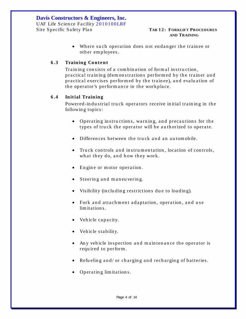
Davis Constructors & Engineers, Inc. UAF Life Science Facility 2010100LRF Site Specific Safety Plan TAB 12: FORKLIFT PROCEDURES AND TRAINING
Page 4 of 14
• Where such operation does not endanger the trainee or other employees.
6.3 Training Content Training consists of a combination of formal instruction, practical training (demonstrations performed by the trainer and practical exercises performed by the trainee), and evaluation of the operator’s performance in the workplace.
6.4 Initial Training Powered-industrial truck operators receive initial training in the following topics:
• Operating instructions, warning, and precautions for the
types of truck the operator will be authorized to operate.
• Differences between the truck and an automobile.
• Truck controls and instrumentation, location of controls, what they do, and how they work.
• Engine or motor operation.
• Steering and maneuvering.
• Visibility (including restrictions due to loading).
• Fork and attachment adaptation, operation, and use
limitations.
• Vehicle capacity.
• Vehicle stability.
• Any vehicle inspection and maintenance the operator is required to perform.
• Refueling and/or charging and recharging of batteries.
• Operating limitations.

Davis Constructors & Engineers, Inc. UAF Life Science Facility 2010100LRF Site Specific Safety Plan TAB 12: FORKLIFT PROCEDURES AND TRAINING
Page 5 of 14
• Any other operating instructions, warnings, or precautions listed in the operator’s manual for the types of vehicle the employee is being trained to operate.
6.5 Workplace-related Topics • Surface conditions where the vehicle will operate.
• Composition of loads to be carried and load stability.
• Load manipulation, stacking and unstacking.
• Pedestrian traffic in areas where the vehicle will be
operated.
• Narrow aisles and other restricted places where the vehicle will be operated.
• Hazardous (classified) locations where the vehicle will be
operated.
• Ramps and other sloped surfaces that could affect the vehicles stability.
• Closed environments and other areas where insufficient
ventilation or poor vehicle maintenance could cause a build up of carbon monoxide or diesel exhaust.
• Other unique or potentially hazardous environmental
conditions in the workplace that could affect safe operation.
6.6 Refresher Training and Evaluation Refresher training, including an evaluation of the effectiveness of that training, is conducted to ensure the operator has knowledge and skills needed to operate the powered-industrial truck safely. Refresher training in relevant topics is provided to the operator when:
• The operator is observed operating the vehicle in an
unsafe manner.

Davis Constructors & Engineers, Inc. UAF Life Science Facility 2010100LRF Site Specific Safety Plan TAB 12: FORKLIFT PROCEDURES AND TRAINING
Page 6 of 14
• The operator is involved in an accident or near-miss incident.
• The operator receives an evaluation revealing the operator
is not operating the truck safely.
• The operator is assigned to drive a different type of truck.
• A condition in the workplace changes in a manner that could affect safe operation of the truck.
• Once every three (3) years and evaluation is conducted of
each powered-industrial truck operator’s performance.
7.0 Safe Operating Procedures (SOP) and Rules • Only authorized and trained personnel will operate PITs. • All PITs are equipped with a headache rack, fire extinguisher,
rotating beacon, back-up alarm, and seat belts. Seat belts are worn at all times by the operator.
• The operator performs daily pre- and post-trip inspections.
• Any safety defects (such as hydraulic fluid leaks, defective
brakes, steering, lights, or horn, and/or missing fire extin-guisher, lights, seat belt, or back-up alarm) is reported for immediate repair or have the PIT taken “Out of Service.”
• Operators follow the proper recharging or refueling safety
procedures.
• Loads are tilted back and carried not more than six inches from the ground. Loads restricting operator’s vision are transported backwards.
• PITs travel no faster than 5 mph or faster than a normal walk.
• Hard hats are worn by PIT operators at all times.
• Operators sound the horn and use extreme caution when
meeting pedestrians, making turns, and cornering.

Davis Constructors & Engineers, Inc. UAF Life Science Facility 2010100LRF Site Specific Safety Plan TAB 12: FORKLIFT PROCEDURES AND TRAINING
Page 7 of 14
• Passengers may not ride on any portion of a PIT. Only the
operator rides PITs.
• If PITs are used as a man lift, an appropriate man-lift platform (care with standard rails and toe-boards) is used.
• Aisles are maintained free from obstructions, marked, and wide
enough (six foot minimum) for vehicle operation.
• Lift capacity is marked on all PITs. Operator assures load does not exceed rated weight limits.
• When unattended PITs are turned off, forks lowered to the
ground, and parking brake applied.
• All PITs (with exception of pallet jacks) are equipped with a multi-purpose dry chemical fire extinguisher (minimum rating is 2A:10B:C).
• Operators are instructed to report all accidents, regardless of
fault or severity, to management. Management conducts an accident investigation.
7.1 Changing and Charging Storage Batteries • Battery charging installations are located in areas
designated for the purpose.
• Facilities are provided for flushing and neutralizing spilled electrolyte, for fire protection, for protecting charging apparatus from damage by trucks and for adequate ventilation for dispersal of fumes from gassing batteries.
• A conveyor, overhead hoist, or equivalent material
handling equipment is provided for handling batteries.
• Reinstalled batteries are properly positioned and secured in the truck.
• A carboy tilter or siphon is provided for handling
electrolyte.

Davis Constructors & Engineers, Inc. UAF Life Science Facility 2010100LRF Site Specific Safety Plan TAB 12: FORKLIFT PROCEDURES AND TRAINING
Page 8 of 14
• When charging batteries, acid is poured into water; water
is not poured into acid.
• Trucks are properly positioned and brake applied before attempting to change or charge batteries.
• Care is taken to assure vent caps are functioning. The
battery (or compartment) cover(s) is open to dissipate heat.
• Smoking is prohibited in charging areas.
• Precautions are taken to prevent open flames, sparks, or
electric arcs in battery charging areas.
• Tool and other metallic objects are kept away from the top of uncovered batteries.
7.2 Operations • If at anytime a powered-industrial truck is found to need
repair, is defective, or in any way unsafe, the truck is taken out of service until it’s restored to safe operating condition.
• Trucks are not driven up to anyone standing in front of a
bench or other fixed object.
• No person is allowed to stand or pass under the elevated portion of any truck—whether loaded or empty.
• Unauthorized personnel are not permitted to ride on
powered-industrial trucks.
• Arms or legs are not placed between the uprights of the mast or outside the running lines of the truck.
• When a powered-industrial truck is left unattended, load
engaging means are fully lowered, controls are neutra-lized, power shut off, and brakes set. Wheels are blocked, if the truck is parked on an incline.

Davis Constructors & Engineers, Inc. UAF Life Science Facility 2010100LRF Site Specific Safety Plan TAB 12: FORKLIFT PROCEDURES AND TRAINING
Page 9 of 14
• A safe distance is maintained from the edge of ramps or platforms while on any elevated dock, or platform, or freight car. Trucks are not used for any activity other than what it was designed for. Follow manufac-turer’s procedures.
• There’s sufficient headroom under overhead installation,
lights, pipes, sprinkler systems, etc. • An overhead guard is used as protection against falling
objects. It should be noted that an overhead guard is intended to offer protection from the impact of small packages, boxes, bagged material, etc. representative of the job application. But, not to withstand the impact of a falling capacity load.
• A load backrest extension is used whenever necessary to
minimize the possibility of the load (or part of it) falling backwards.
• Trucks are not parked in a way to block fire aisles, access
to stairways, or fire equipment. •
7.3 Traveling • All traffic regulations are observed including authorized
speed limits. A safe distance is maintained approximately three truck lengths from the truck ahead, and the truck is kept under control at all times.
• The right of way is yielded to ambulances, fire trucks, or
other vehicles in emergency situations.
• Other trucks traveling in the same direction at inter-sections, blind spots, or other dangerous locations are not passed.
• The driver is required to slow down and sound the horn
at cross aisle and other locations where vision is obstructed. If the load being carried obstructs forward view, the driver is required to travel with the load trailing.

Davis Constructors & Engineers, Inc. UAF Life Science Facility 2010100LRF Site Specific Safety Plan TAB 12: FORKLIFT PROCEDURES AND TRAINING
Page 10 of 14
• Railroad tracks are crossed diagonally wherever possible. Parking closer than 8 feet from the center of railroad tracks is prohibited.
• The driver is required to look in the direction of and keep
a clear view of the path of travel.
• Grades are ascended and descended slowly. When ascend-ing or descending grades in excess of 10 percent loaded trucks are driven with the load upgrade. On all grades the load and load-engaging means are tilted back if applicable, and raised only as far as necessary to clear the road surface.
• Under all travel conditions the truck is operated at a
speed permitting it to be brought to a stop in a safe manner.
• Stunt driving and horseplay are not permitted.
• The driver is required to slow down for wet and slippery
floors.
• Dock board or bridge plates are properly secured before driven over. Dock board or bridge plates are driven over carefully and slowly and their rated capacity never exceeded.
• Running over loose objects on the roadway is avoided.
• While negotiating turns speed is reduced to a safe level by
means of turning the hand steering wheel in a smooth, sweeping motion. Except when maneuvering at very low speed, the hand steering wheel is turned at a moderate, even rate.
7.4 Loading • Only stable or safely arranged loads are handled.
Caution is exercised when handling off-center loads which cannot be centered.

Davis Constructors & Engineers, Inc. UAF Life Science Facility 2010100LRF Site Specific Safety Plan TAB 12: FORKLIFT PROCEDURES AND TRAINING
Page 11 of 14
• Only loads within the rated capacity of the truck are handled.
• The long or high (multiple-tiered) loads which may affect
capacity are adjusted.
• Trucks equipped with attachments are operated as partially loaded trucks when not handling a load.
• A load engaging means is placed under the load as far as
possible; the mast is carefully tilted backward to stabilize the load.
• Extreme care is used when tilting the load forward or
backward particularly when high tiering. Tilting forward with load engaging means elevated is prohibited except to pick up a load. An elevated load is not tilted forward except when the load is in a deposit position over a rack or stack. When stacking or tiering, only enough backward tilt to stabilize the load is used.
7.5 Fueling Safety • Fuel tanks are not filled while the engine is running.
Spillage is avoided.
• Spillage of oil or fuel is carefully washed away or completely evaporated and the fuel tank cap replaced before restarting engine.
• No truck operates with a leak in the fuel system!
• Open flames are not used for checking electrolyte level in
storage batteries or gasoline level in fuel tanks.
7.6 Maintenance of Powered-Industrial Trucks • Any power-operated industrial truck not in safe operating
condition is removed from service. All repairs are made by authorized personnel.
•

Davis Constructors & Engineers, Inc. UAF Life Science Facility 2010100LRF Site Specific Safety Plan TAB 12: FORKLIFT PROCEDURES AND TRAINING
Page 12 of 14
• Those repairs to the fuel and ignition system of industrial
trucks which involve fire hazards are conducted only in locations designated for such repairs.
• Trucks needing repair to the electrical system have the
battery disconnected prior to such repairs.
• All industrial truck parts are replaced only with parts equivalent to those used in the original design so safety is maintained.
• Industrial trucks are not altered in ways changing the
relative positions of the various parts from what they were when originally received from the manufacturer. Nor, are they altered either by the addition of extra parts not provided by the manufacturer or by the elimination of any parts. Additional counter-weighting of fork trucks is not done unless approved by the truck manufacturer.
• Industrial trucks are examined before placing in service,
and are not placed in service if the examination shows any condition adversely affecting the safety of the vehicle. Such examinations are made at least daily. Where industrial trucks are used on a round-the-clock basis, they’re examined prior to each shift. Defects found are immediately reported and corrected.
• When the temperature of any part of any truck is found to
be in excess of its normal operating temperature (creating a hazardous condition) the vehicle is removed from service and not returned until the cause for overheating is eliminated.
• Industrial trucks are kept in a clean condition, free of lint,
excess oil, and grease. Non-combustible agents are used for cleaning trucks. Low flash point (below 100 deg. F.) solvents are not used. High flash point (at or above 100 deg. F.) solvents may be used.
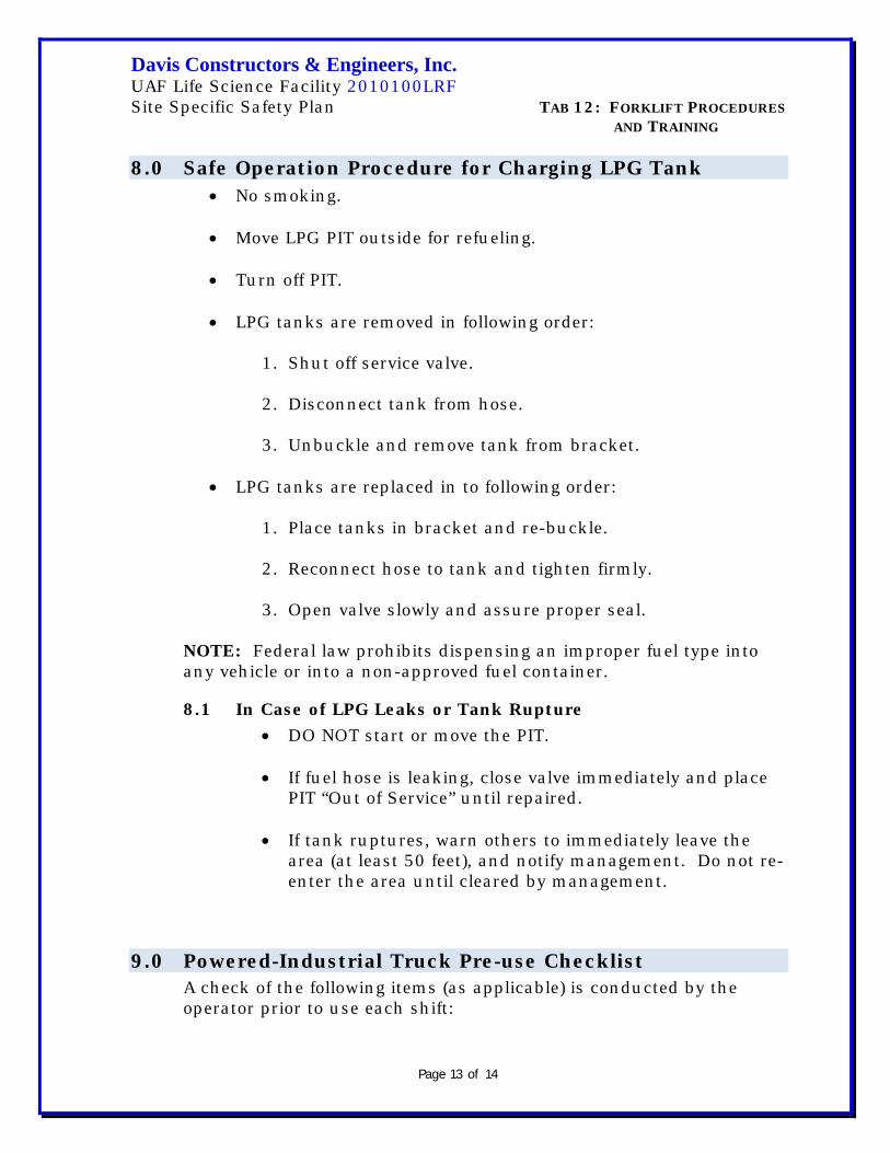
Davis Constructors & Engineers, Inc. UAF Life Science Facility 2010100LRF Site Specific Safety Plan TAB 12: FORKLIFT PROCEDURES AND TRAINING
Page 13 of 14
8.0 Safe Operation Procedure for Charging LPG Tank • No smoking. • Move LPG PIT outside for refueling.
• Turn off PIT.
• LPG tanks are removed in following order:
1. Shut off service valve. 2. Disconnect tank from hose.
3. Unbuckle and remove tank from bracket.
• LPG tanks are replaced in to following order:
1. Place tanks in bracket and re-buckle.
2. Reconnect hose to tank and tighten firmly.
3. Open valve slowly and assure proper seal.
NOTE: Federal law prohibits dispensing an improper fuel type into any vehicle or into a non-approved fuel container.
8.1 In Case of LPG Leaks or Tank Rupture • DO NOT start or move the PIT. • If fuel hose is leaking, close valve immediately and place
PIT “Out of Service” until repaired. • If tank ruptures, warn others to immediately leave the
area (at least 50 feet), and notify management. Do not re-enter the area until cleared by management.
9.0 Powered-Industrial Truck Pre-use Checklist A check of the following items (as applicable) is conducted by the operator prior to use each shift:

Davis Constructors & Engineers, Inc. UAF Life Science Facility 2010100LRF Site Specific Safety Plan TAB 12: FORKLIFT PROCEDURES AND TRAINING
Page 14 of 14
• Lights
• Horn
• Brakes
• Leaks
• Warning beacon
• Back-up warning alarm
• Fire extinguisher If any deficiencies are noted, the unit is placed “Out of Service” until the problem is corrected. Additionally, it’s the operator’s responsibility to notify the immediate supervisor and fill out a maintenance request. See Daily and Monthly inspection checklists.
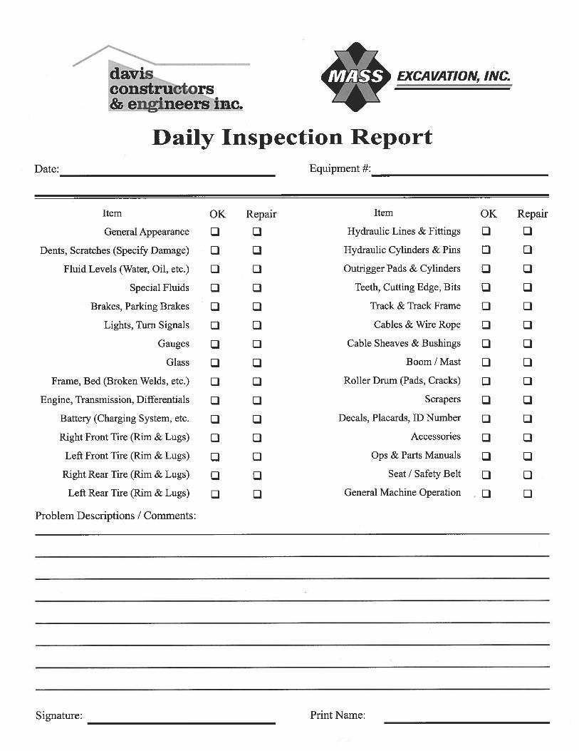
Adele Bacon
Rectangle

Adele Bacon
Rectangle

Davis Constructors & Engineers, Inc. UAF Life Science Facility 2010100LRF Site Specific Safety Plan TAB 13: AERIAL LIFT AND SCISSOR LIFT PROCEDURE
Page 1 of 11
Aerial Lift and Scissor Lift Procedure
1.0 Purpose and Scope This safety procedure provides minimum requirements for use of aerial and scissor lifts. This work instruction applies to all aerial lifts including extensible and articulating boom platforms, aerial ladders, vertical towers, vertical mast lifts, and scissor lifts. This procedure applies to all employees and subcontractors covered by the UAF Life Science Facility, Site-Specific Safety Plan (SSSP).
2.0 Responsibilities General responsibilities for SSSP implementation are stated in Tab 3 – Safety Policy and Procedures of this document. Additional management, staff, specific to this topic is stated in this procedure.
2.1 Superintendent and or Project Safety Manager • Designate a Competent Person(s) to conduct all aerial lift
training and inspection using the form/procedures found in appendices.
• Ensure only approved lifts are used. • Determine whether egress and access from elevated lifts are
necessary and document approval or disapproval for each specific request.
2.2 Supervisors • Ensure all employees operating aerial devices are trained in
accordance with this SSSP and relevant national legislation and other regulatory requirements.
• Ensure approved lifts are used and that they’re properly inspected and maintained.
• Monitor aerial and scissor lift operations to assure compliance with this safety plan.
2.3 Employees • Successfully complete the aerial lift operator training required
by this SSSP prior to operating an aerial or scissor lift. • Operate aerial lifts in accordance with training received,
manufacturer’s recommendations, and this SSSP.

Davis Constructors & Engineers, Inc. UAF Life Science Facility 2010100LRF Site Specific Safety Plan TAB 13: AERIAL LIFT AND SCISSOR LIFT PROCEDURE
Page 2 of 11
• Promptly report defective or malfunctioning equipment and any
incident involving the use of aerial or scissor lifts to the supervisor.
3.0 Definitions
Term Definition
Aerial Ladder
A manually or self-propelled aerial device consisting of a single or multiple section extensible ladder with a personnel platform.
Aerial Lift
Self-propelled elevating work platform positioned by telescoping boom, articulating boom, or vertical mast primarily designed as a personnel carrier attached to a rotating or non-rotating base that permits elevation of the free or outer end.
Approved Lifts See Paragraph 4.2
Articulating Boom A boom with two or more hinged sections that extends by unhinging.
Competent Person
One who is capable of identifying existing and predictable hazards in the surroundings or working conditions which are unsanitary, hazardous, or dangerous to employees, and who has the authorization to take prompt corrective measures to eliminate hazards.
Extensible Boom Platform
An aerial device with a telescopic boom and personnel platform attachment.
Fall Restraint
A fall-protection system that prevents the user from falling any distance. The system is comprised of a full-body harness, along with an anchorage, connectors, and other necessary equipment. The system prevents and/or restrains the user from reaching the open edge of the structure or platform.
Insulated Aerial Lift An aerial device designed for work on energized electrical lines and apparatus.
Lift(s) Any vehicle mounted, manually propelled, or self-propelled device, extensible or articulating, or both, designed to

Davis Constructors & Engineers, Inc. UAF Life Science Facility 2010100LRF Site Specific Safety Plan TAB 13: AERIAL LIFT AND SCISSOR LIFT PROCEDURE
Page 3 of 11
position personnel. This term is also used as an abbreviation for aerial devices and aerial platforms including aerial lifts and scissor lifts.
Lift Operator A qualified person who controls the movement of the lift.
Platform Any personnel-carrying device (e.g. basket or bucket), which is a component of an aerial device.
Personal Fall
A system used to arrest an employee in a fall from a working level. It includes anchorage, connectors, a full-body harness, and may include a lanyard, deceleration device, lifeline, or a suitable combination of these.
Scissor Lift A self-propelled elevating work platform utilizing a scissor type framework for positioning the platform vertically and is primarily designed as a personnel carrier.
4.0 Procedure Only trained, qualified, and authorized employees are to operate lifts and, where necessary, the employees are named in the work plan. Plan the work! Inspect work area for hazards, such as overhead and ground-level obstructions and electrical hazards, other lifts, conflicting work operations, traffic, potholes, and wind speeds above manufacturer limits. Do not operate above 30 mph (45 kmh). Always use approved lifts. See paragraph 4.4. Maintain required distances for work near or on live electrical lines. See paragraph 4.5. Always select the proper type of lift based on the intended use.
4.1 General Requirements Aerial lifts should only be operated on firm, level surfaces. Lifts will not be driven on grades, side slopes, or ramps with slopes exceeding manufacturers incline limits. If the machine has a separate power source to operator the movement of the base (e.g. truck mounted) vs. the movement of the platform, the vehicle engine must be shut off and the key removed before using the platform.
Davis Constructors & Engineers, Inc. UAF Life Science Facility 2010100LRF Site Specific Safety Plan TAB 13: AERIAL LIFT AND SCISSOR LIFT PROCEDURE
Page 4 of 11
Truck mounted aerial devices are lowered and secured prior to driving the truck or vehicle on the highway. When so equipped, outriggers or stabilizers and extendable axels are fully extended and placed on firm level surfaces or mats. Outrigger or stabilizer mats and pads are:
o At least three (3) times larger in surface area than the float they support,
o Flat where the outrigger or stabilizer contacts it to prevent the lift from sliding off, and
o Strong enough to withstand the loads imposed by the outrigger.
Lift controls are operated in a smooth, controlled manner at all times. Avoid sudden starts, stops, or change in direction. Never jam the controls from one travel direction to another. Keep all body parts inside the machine while moving equipment. When boom lifts must be moved on an incline, the boom is always positioned uphill of the wheels and the wheels chocked, if it’s parked on an incline. See manufacturer instructions for incline limits. Never use the boom to push or pull the aerial lift base or any other object. Boom and basket load limits specified by the manufacturer are not exceeded. Care is taken to prevent electric cords, rope, and hoses from becoming entangled in the aerial platform. Only the tools and materials required to perform the work are permitted in the platform and must fit completely inside the basket. Small tools and materials are kept in a properly secured container on the floor of the platform. Supporting equipment, material, or rigging loads from the boom, handrails, or platform is prohibited.
Davis Constructors & Engineers, Inc. UAF Life Science Facility 2010100LRF Site Specific Safety Plan TAB 13: AERIAL LIFT AND SCISSOR LIFT PROCEDURE
Page 5 of 11
If lift or supporting assembly becomes caught or otherwise prevented from normal motion by adjacent structures or obstacles, and control reversal does not free the lift, all personnel are removed from the platform before additional attempts are made to free the lift using the ground controls. A fire extinguisher of not less than 5 BC rating must be available and secured on the platform of lifts.
4.2 Fall Protection Employees must wear a personal fall-protection harness and lanyard which is attached to a manufacturer-approved attachment point in the platform or basket when working from a lift. If a manufacturer-approved attachment point is not provided, a Qualified Person determines the proper anchor point location specific to each type of lift. It’s recommended that lanyards used for lifts be as short as possible to restrain an employee from being thrown from the platform. Guardrails are in place and access gates closed while lift is in use. Employees always stand firmly on the floor of the basket and do not sit or climb on the edge of the basket or use planks, ladders, or other objects in the platform to gain a work position or as a climbing device to access other work levels. The floor of the platforms must be kept clear of trash, debris, etc. Lifts are not moved when the platform is elevated with personnel in the basket unless:
the travel surface is level, the equipment is designed for that purpose, and manufacturer’s instructions allow it.
For aerial lifts the platform is below horizontal for traveling. The operator limits travel speed according to conditions of ground surface, congestion, visibility, slope, location of personnel, and other factors that could cause collisions or injuries.

Davis Constructors & Engineers, Inc. UAF Life Science Facility 2010100LRF Site Specific Safety Plan TAB 13: AERIAL LIFT AND SCISSOR LIFT PROCEDURE
Page 6 of 11
4.3 Protection of Personnel in Immediate Work Area The counterweight swing radius of articulating or extensible boom lifts is barricaded to prevent crushing injuries to employees on the ground. When the lift is operated in elevated positions the area underneath the work is barricaded. Elevated platforms are attended at all times or lowered to grade. When lowering elevated platforms the operator must inspect the area around the machine to ensure no personnel, equipment, or obstructions are in the path of travel. If the area in the path of movement is not visible, i.e., in a cloud of steam or fog, the basket is not lowered until vision is restored or the area is otherwise determined to be clear. A spotter is utilized whenever the operator cannot see the machine base during movement of the base. A spotter is used when operating lifts in close proximity to obstructions, operating equipment, vehicles, or personnel. 4.4 Approved Aerial/Scissor Lifts 4.4.1 General Requirements Only lifts meeting Davis and regulatory requirements are used. Articulating boom and extensible boom platforms must have both upper (platform level) and lower (ground level) controls. Lower controls override upper controls but are not operated unless permission was obtained from the employee in the lift, except in case of emergency. All lift platform controls have two points of activation contact (normally a foot pedal and control lever) by the operator to activate the directional controls (horizontal and vertical movement). With a time-delay feature the delay is set to no more than three (3) seconds. Any other manufacturer supplied interlocks are operational. Lifts have:
• Top rails, mid-rails, and toe boards unless completely enclosed on the sides,

Davis Constructors & Engineers, Inc. UAF Life Science Facility 2010100LRF Site Specific Safety Plan TAB 13: AERIAL LIFT AND SCISSOR LIFT PROCEDURE
Page 7 of 11
• Anchor points for fall-arrest equipment (see TAB ### in SSSP), and
• Provision for storage of the equipment manual and the manual are available on each machine.
Scissor lifts have provision for manually blocking the lift open during inspection and maintenance operations. Electric- or propane-powered lifts are considered for indoor applications. Gasoline- or diesel-powered lifts are only used outdoors or in well-ventilated areas. Modifications, attachments, or use for purposes other than as designed are approved in writing by the manufacturer prior to use. Only lifts approved for use in hazardous locations and atmospheres such as areas with explosive vapors, dust, etc. are used in defined hazardous locations. 4.5 Elevated Lift Egress and Access Exiting and accessing an elevated platform is permissible only when it’s determined to be the safest means of access to an elevated work area. This determination is documented and has prior approval by the site manager or the site safety supervisor. When authorized the following minimum procedures are used to access or exit an elevated platform.
• Obtain documented approval from site manager or site safety supervisor.
• The platform is attended at all times by a lift operator while any personnel are exiting or accessing an elevated platform.
• 100 percent tie-off is maintained while exiting or entering the platform. The employee secures a second lanyard to an anchorage point outside the basket before disconnecting his lanyard from the lift and exiting. When re-enter-ing secure second lanyard to the lift only after

Davis Constructors & Engineers, Inc. UAF Life Science Facility 2010100LRF Site Specific Safety Plan TAB 13: AERIAL LIFT AND SCISSOR LIFT PROCEDURE
Page 8 of 11
both feet are on the floor of the basket then release the lanyard tied to outside anchorage.
• The floor of the basket is at the same level as the structure to be accessed.
• At no time do employees exit or enter over the lift controls.
• Access gates are utilized if at all possible to exit or enter the elevated platform.
• If the manufacturer prohibits egress and access of an elevated lifting platform, such practices are prohibited unless written approval is obtained from the manufacturer.
4.6 Fueling and Recharging Equipment The equipment is lowered to grade, parked, and shut down prior to refueling or battery charging. Fueling and battery charging is done in a well-ventilated area free from flame, sparks, or other hazards that may cause a fire or explosion because of the fuel or the hydrogen generated from battery charging. Follow all manufacturer requirements for fueling or charging batteries. For battery charging connect charger to battery prior to turning it on. Turn the charger off prior to removing charger leads. Wear appropriate PPE while fueling or charging batteries. 4.7 Inspections All lifts are inspected by a competent person:
• Upon arrival at a jobsite and • Quarterly or every 200 hours, whichever comes first.
Lifts must have visual inspections performed by the operator prior to use. Defective equipment is tagged out-of-service and is immediately removed from service. 4.7.1 Visual Pre-use Inspection

Davis Constructors & Engineers, Inc. UAF Life Science Facility 2010100LRF Site Specific Safety Plan TAB 13: AERIAL LIFT AND SCISSOR LIFT PROCEDURE
Page 9 of 11
Prior to use all aerial lifts are inspected using a pre- shift inspection log sheet. The subsequent operator using the lift during the same shift ensures a pre-shift inspection was completed prior to use. Lift controls are tested prior to each use to determine whether they’re in safe working condition. The ground controls are checked first for those units with ground controls. Visual inspection items include the following:
• Controls plainly and legibly marked as to their function,
• Evidence that safety devices and interlocks are operational,
• Personal protective equipment for operator and riders, e.g. fall protection, gloves,
• Hydraulic system for tight connections, hose damage, and leaks,
• Cables and wiring, • Loose or missing parts, • Legible warning placards and decals (replace
defective placards or decals prior to equipment use),
• Outriggers, stabilizers, and extensible axles, • Guardrail systems and gate latches, • Other items recommended by manufacturer.
4.7.2 Documented Periodic Inspection A documented periodic inspection is performed by a competent person.
**All equipment coming on the site, whether rental, Davis owned or subcontractor owned shall be subject to the following criteria. Equipment not in compliance will not be allowed to be used on the site for any activity. The required elements are:
1. A legible operating manual complete with maintenance requirements;
2. daily and quarterly inspection forms;

Davis Constructors & Engineers, Inc. UAF Life Science Facility 2010100LRF Site Specific Safety Plan TAB 13: AERIAL LIFT AND SCISSOR LIFT PROCEDURE
Page 10 of 11
3. and a completed inspection form filled out by the equipment vendor or owner immediately prior to delivery.
• When a lift is delivered to a site, • At least quarterly or every 200 hours of operation
(whichever comes first), and • After any incident involving the lift.
4.8 Maintenance A preventive maintenance program is established ensuring manufacturer maintenance requirements are met. Maintenance personnel assist with periodic inspections. Only qualified personnel perform repairs on lifts. Any problems or malfunctions affecting safe operations are repaired and functionally tested before use. Properly support booms, extended scissor sections, etc., during maintenance operations on the hydraulic systems. Follow lockout procedures. All repairs are documented.
5.0 Operator Qualification and Training The aerial and scissor lift qualification for lift operators includes training and a skills demonstration. 5.1 Training A valid motor vehicle license is used as proof of adequate vision and is substituted for the vision-screening requirement on the medical questionnaire. Lift operators are trained by a designated Competent Person. Manufacturer representatives are recognized as being competent on their equipment and are considered Competent Persons to satisfy the requirements of this work instruction.
As a part of the training, prospective operators must review t operations manual, the site specific safety requirement for each lift they need to qualify for.

Davis Constructors & Engineers, Inc. UAF Life Science Facility 2010100LRF Site Specific Safety Plan TAB 13: AERIAL LIFT AND SCISSOR LIFT PROCEDURE
Page 11 of 11
Lift operators may require additional training when: • assigned to a different type or model lift • has not been operating safely, or • is involved in a lift-related accident and/or incident
5.2 Operator Skills Demonstration: The skills portion of this procedure is designed to verify the prospective operator possesses the actual skills required to operate each type of aerial or scissor lift. The exercise is performed with the exact type of equipment the prospective operator may be authorized to operate. A designated Competent Person administers the practical skills portion of this procedure in a safe environment and under controlled conditions. Skills demonstration includes inspecting the lift, starting /stopping, raising/lowering, where applicable rotating /extending/retracting the boom, and moving the lift from one location to another.
The Competent Person documents completion of the operators skills exercise by informing the Project Safety Manager in writing. These records will be maintained in the Project Safety Office.

Davis Constructors & Engineers, Inc. UAF Life Science Facility 2010100LRF Site Specific Safety Plan 10-322 TAB 14: LADDER SAFETY PROGRAM
Page 1 of 6
Ladder Safety Program
Purpose: To set forth rules and regulations giving direction in the building of ladders that not only meet Federal and State OSHA regulations, but also provide safe access and work area for Davis employees. Background: Falls from ladders account for a large number of injuries and deaths in the construction industry each year. The goal of Davis is to eliminate these hazards from our projects. Procedure: Ladders are used on most construction projects. They may be fixed or portable and be either manufactured or job-made. Ladders can be made of wood, aluminum, steel, fiberglass or a combination of these materials. The regulations covering the construction, components and use of ladders are contained in OSHA (federal/State) Standards and ANSI Standards A14.l, A14.2, and Al4.3, and they should be referred to for complete details and specifications. Ladder safety criteria:
1. All ladders must be in good condition without damage. 2. Stepladders are used only in the full open position and are never leaned up
against something and used as an extension ladder. 3. All other types of ladders (except for some special fixed ladders) must be
used in a position no less than one-fourth the distance from the ladder base to the top support.
4. Straight ladders have safety feet or are blocked or scabbed to prevent
slippage, are tied off, or otherwise secured at the top and extend at least 3′ above the level of access, if it’s a roof, floor, or other elevated area.
5. Aluminum and steel ladders are not used when electrical power sources are
present. 6. Personnel should always face the ladder when using it and should use both
hands while climbing.

Davis Constructors & Engineers, Inc. UAF Life Science Facility 2010100LRF Site Specific Safety Plan 10-322 TAB 14: LADDER SAFETY PROGRAM
Page 2 of 6
7. If materials are needed for work tasks, materials are placed in a work belt or are raised to the work point using ropes or cables.
8. Personnel clean their shoes before they climb a ladder. 9. Ladders are not placed in front of doors or other devices that may be moved
into the ladder.
10. The maximum length of a single cleat ladder must not exceed 30.′ 11. Permanent fixed ladders over 20′ in length are equipped with safety cages
(121-5(j)). They may also require platforms at 20′ intervals. 12. The minimum standards for job-made ladders are:
• Side rails on single cleat ladder up 16′ should be made of 2″ x 4″ lumber. Those over l6′ up to the maximum limit of 30′ should be 3″ x 6″ lumber.
• Side rails and midrails on double cleat ladders up to 12′ should be made of 2″ x 4″ lumber. Those over l2′ up the maximum of 24′ should 2″ x 6″ lumber.
• Cleats should be made from 2″ x 4″ lumber, be spaced at 12″ intervals and be neither less than 15″ wide nor more than 20″ wide.

Davis Constructors & Engineers, Inc. UAF Life Science Facility 2010100LRF Site Specific Safety Plan 10-322 TAB 14: LADDER SAFETY PROGRAM
Page 3 of 6
Ladder Placement • Feet are placed on a substantial base and the area around the top and
bottom are kept clear. • Pitch is 1/4 of the working length. • Side rails extend 36″ above the landing or grab rails provided. • Ladders are tied, blocked or otherwise secured to prevent their being
displaced. • Ladders are not used in a horizontal position as platforms, runways, or
scaffolds.

Davis Constructors & Engineers, Inc. UAF Life Science Facility 2010100LRF Site Specific Safety Plan 10-322 TAB 14: LADDER SAFETY PROGRAM
Page 4 of 6
Cleats Cleats are inset into the edges of the side rails V2 inch, or filler blocks used between the cleats. Cleats are secured with three 10d common wire nails (or equivalent). Double headed nails are not used. Cleats are spaced 12″ top to top. When using ¾″ thick _______ _______ ________________________________________________ Cleats, the width is Width determined by the Length of Cleat (inches) (inches) length of the cleat as Up to and including 20 ……………………………………… 3 indicated at the right. Over 20 and up to and including 30……………………… 3 ¾ Species of Wood Acceptable for ¾″ Thick Cleats Oregon Ash Pumpkin Ash White Ash Beech Birch Rock Elm Soft Elm Hackberry Hickory
Holly Western Larch Locust Hard Maple Red Maple Red Oak White Oak Pecan Persimmon
Southern Yellow Pine Tamarack
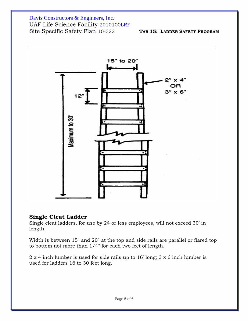
Davis Constructors & Engineers, Inc. UAF Life Science Facility 2010100LRF Site Specific Safety Plan 10-322 TAB 15: LADDER SAFETY PROGRAM
Page 5 of 6
Single Cleat Ladder Single cleat ladders, for use by 24 or less employees, will not exceed 30′ in length. Width is between 15″ and 20″ at the top and side rails are parallel or flared top to bottom not more than 1/4″ for each two feet of length. 2 x 4 inch lumber is used for side rails up to 16′ long; 3 x 6 inch lumber is used for ladders 16 to 30 feet long.

Davis Constructors & Engineers, Inc. UAF Life Science Facility 2010100LRF Site Specific Safety Plan 10-322 TAB 15: LADDER SAFETY PROGRAM
Page 6 of 6
Double Cleat Ladder
Double cleat ladders are provided for 25 or more employees or two-way traffic and do not exceed 24′ in length. Side and middle rails are 2″ x 4″ lumber up to 12′ in length and 2″ x 6″ lumber from 12″ to 24′ in length.

Davis Constructors & Engineers, Inc. UAF Life Science Facility 2010100LRF Site Specific Safety Plan 10-322 TAB 15: RESPIRATORY PROTECTION PLAN
Page 1 of 7
Respiratory Protection Plan
1.0 Introduction The Respiratory Protection Plan described in this document is intended to conform to the current OSHA Regulations, 29 CFR 1910.134.
The law states a written Respiratory Protection Plan must be established by the employer for selection and use of respirators, for use at existing or potentially hazardous or toxic work sites, or for any asbestos abatement work. The Respiratory Protection Plan includes a specifically mandated 11-point program. This 11-point program was used as an outline for a written Respiratory Protection Plan, as described in the following paragraphs.
2.0 Program
2.1 Selection and Use of Respirators Appropriate types of administrative and engineering controls are used to reduce the levels of exposure to hazardous and toxic materials before selecting respirators. These controls may include establishing policies such as appropriate air monitoring of areas prior to entering, using wet techniques for dust control, and effective use of ventilation, negative air machines, enclosures, or sprays, and wind direction when applicable.
When such controls are not feasible or the containment level after use of controls is still potentially above the permissible exposure level, appropriate respiratory protection is provided by Davis Constructors & Engineers, Inc. (Davis) and used by the employee. Employees are required to sign a respirator fit test (Appendix 2) and training form (Appendix 4) stating they’ve read and understand this program prior to using respiratory equipment. The respirator protection program is administered by the Safety Coordinator or a designee. This includes proper use, fit testing of respirators, training programs, and recordkeeping.

Davis Constructors & Engineers, Inc. UAF Life Science Facility 2010100LRF Site Specific Safety Plan 10-322 TAB 15: RESPIRATORY PROTECTION PLAN
Page 2 of 7
2.2 Respiratory Selection Respiratory equipment is selected based on the hazards the worker may be exposed to. This selection is based on the criteria found in ANSI Z88.2. Both personal and environmental air monitoring is performed on a level, intensity, and schedule sufficient for initial selection of respiratory equipment and to either upgrade or downgrade as necessary during the course of the work.
All respiratory equipment selected conforms to National Institute for Occupational Safety and Health (NIOSH) guidelines and will retain NIOSH approvals. Respirators include the following information:
• an assigned identification number, • a label identifying the type of hazard the unit is designed to
protect against and, • information concerning the limitations and approved com-
ponent parts for this type of unit.
2.3 Training in the Use of Respirators All employees using or who may use respirators are properly trained. Training addresses selection of the respirator, seal checking the face piece, proper use of the respirator in the situation, hazards anticipated, inspection and maintenance of the respirator, cleaning and disinfecting, and storage techniques. Most of these topics are covered in subsequent sections of this plan.
Training is documented (Appendix 4) and made a part of each employee’s permanent records. The program also includes formal qualitative-fit testing using amyl acetate and/or irritant smoke before using a particular type of respirator. Each employee completes a fit-test form upon completion of his or her fit test (Appendix 2). Employees are allowed to wear the unit in an uncontaminated area for at least 30 minutes before using them in a contaminated area. Fit tests, medical determinations and other records related to the respiratory protect-ion program are kept by the health and safety department for the period of time required by regulation.
2.4 Respirator Assignment Whenever possible, employees are assigned their own respirator. They mark their unit with a unique number to use and be

Davis Constructors & Engineers, Inc. UAF Life Science Facility 2010100LRF Site Specific Safety Plan 10-322 TAB 15: RESPIRATORY PROTECTION PLAN
Page 3 of 7
responsible for the unit for the duration of a specific project or for the life of the unit, if appropriate. This tends to cause employees to take better care of the unit and do a better job of cleaning and maintaining it. It also prevents germs from colds, flu, etc. from passing from one individual to another.
If individual assignment of units is not possible, the units are thoroughly cleaned and disinfected by each person immediately after using the unit and by the next person before using it.
When different types of respirators including different brands, sizes, or basic types (supplied vs. air purified) are used, the worker receives brief instructions on the use of the different respirator and undergoes and passes a qualitative-fit test. A card is issued to each person telling what respirator they’re assigned and fit tested for.
2.5 Respiratory Cleaning and Disinfecting Respirators are cleaned after each day’s use. The filter cartridges are disposed of after each day’s use or more often if required by the site safety person or as the situation dictates. The respirators are rinsed off in the shower or in the washbasin with the headbands removed, depending on the type of respirator. The entire unit is cleaned in hot, soapy water (less than 120 degrees F). A pliable hand brush is used if the unit is exceptionally dirty. The unit is rinsed in clean, warm water and then rinsed in a disinfectant solution such as 50 ppm iodine or chlorine (1 teaspoon in 1 gallon of water) then thoroughly dried both inside and outside the face piece.
The units are air dried overnight in a clean area. If not being used again immediately, units are:
• inspected and any worn or defective parts replaced, • reassembled and placed in clean, marked Ziploc® plastic
bags for storage in a cool, dry place. • inserted in the storage bag so the unit’s unique number is
visible.
Organic solvents are not used for cleaning, because they deteriorate the rubber of the face piece. Respirator bags are not closed until units are completely dry (at least 48 hours).

Davis Constructors & Engineers, Inc. UAF Life Science Facility 2010100LRF Site Specific Safety Plan 10-322 TAB 15: RESPIRATORY PROTECTION PLAN
Page 4 of 7
2.6 Storage Respirators are stored in a cool, dry, dark location inside plastic bags and/or boxes clearly marked with the unique number, the brand name, model number, and the unit size.
The unit is stored with the face piece down to protect the rubber from assuming an abnormal shape and essentially ruining it. The storage location affords protection against dust, chemicals, sunlight, and extreme heat or cold, like inside a metal or wood cabinet. Cartridges are not stored in bags with face pieces.
The inhalation valve of each mask is taped over with duct tape during temporary or long-term storage, if not kept in a Ziploc® bag to prevent dust or fibers from entering the unit.
Stored units are inspected at least once a month to ensure no distortion of the rubber is taking place.
2.7 Maintenance and Inspection Inspection of respirators includes checking condition of the:
• glass faceplate for scratches, cracks, etc, • condition of the rubber of the face piece, • headbands for elasticity and damage, • valves, both inhalation and exhalations, for fit, presence of
dirt, hair and pliability, • cartridge fittings are checked for cracks, • Hoses are inspected, all fittings and connections are checked
for leaks, cracks and pliability, • clamps for tightness and exposure, • quick-connects or threads for damage, • dangerous clamps (those that might cut you) and other
safety problems are eliminated from each unit.
Special care is taken if exposures to Permissible Exposure Limits (PELs) greater than the Short-Term Exposure Limits (STELs) or Immediately Dangerous to Life and Health (IDLH) atmospheres are encountered.
2.8 Medical Surveillance Prior to participating in situations requiring respirators, employees receive baseline physical exams including the medical
Davis Constructors & Engineers, Inc. UAF Life Science Facility 2010100LRF Site Specific Safety Plan 10-322 TAB 15: RESPIRATORY PROTECTION PLAN
Page 5 of 7
questionnaire in 1910.134 Appendix C. A copy of this medical questionnaire is at the end of this section (Appendix 1). The physician may also perform a Forced Expiratory Volume in one second (FEV 1.0) and a Total Vital Capacity (TVC) test on each person intending to use a respirator to help determine physical ability to safely wear respiratory equipment.
The physician then issues a written medical opinion as to the abil-ity of the employee to wear a respirator and perform the tasks in question.
Medical examinations are:
• repeated annually, • after a major change in job responsibilities, • after an incident involving exposure or onset of any
symptoms or, • upon termination of the employee.
Employee records concerning medical surveillance are kept for 30 years after employment.
2.9 Approved Respirators As stated previously, only NIOSH-approved respiratory equipment, including cartridges, are used. Respirators are not used when out of date. Cartridges and filters must be color coded for use according to NIOSH.
2.10 The Evaluation of Respiratory Protection Plan On the basis of inspections, comments, and changes in the workplace, the program administrator and employees review this written Respiratory Protection Plan annually. This ensures the plan is adequate and achieves state-of-the-art practices. Necessary changes are made to the Respiratory Protection Plan as required to conform to new or existing state or federal regulations. An independent Industrial Hygienist also reviews the program on an annual basis and comments on and updates the program when required.
2.11 Other Items The following items are also covered under Davis Respiratory Protection Plan:

Davis Constructors & Engineers, Inc. UAF Life Science Facility 2010100LRF Site Specific Safety Plan 10-322 TAB 15: RESPIRATORY PROTECTION PLAN
Page 6 of 7
a) A Quality Assurance Plan is employed ensuring the
respirator plan is used and enforced.
b) Facial hair in the form of beards and long sideburns (which may interfere with the fit of the respirator) are not allowed for employees required to wear respirators.
c) IDLH (those Immediately Dangerous to Life or Health), Level
A work, work in explosive atmospheres, and SCBA respirators are not covered by this Plan and are not worked in by Davis employees unless the plan is updated to include such activities.
d) If entered, Permit Required Confined Spaces requires:
1) An attendant in verbal or sight communication with
the worker at all times.
2) Respiratory protection for the attendant is worn at least equivalent to the worker.
3) Written permission from Davis management in the
form of a signed entry permit.
4) Workers never enter areas with low oxygen (less than 19.5 percent) with air-purifying respirators.
5) Temple eyepieces cannot be worn while using full-face
respirators. Eyeglass lens clips are provided, if requested.
6) Contact lenses are never worn with respirators.
7) All employees involved in confined-space entry are
trained to the extent required by law for their duties.
3.0 Fit-Testing Procedure The employer ensures an employee using a right-fitting face piece respirator is fit tested prior to initial use of the respirator, whenever a

Davis Constructors & Engineers, Inc. UAF Life Science Facility 2010100LRF Site Specific Safety Plan 10-322 TAB 15: RESPIRATORY PROTECTION PLAN
Page 7 of 7
different respirator face piece (size, style, model or make) is used, and at least annually thereafter.
The fit test is administered using an OSHA-accepted Qualitative Fit Test protocol. The OSHA-accepted QLFT protocols and procedures are contained in Appendix A of 1910.134.
QLFT may only be used to fit test negative pressure air-purifying respirators that must achieve a fit factor or 100 or less.
Fit testing of tight-fitting atmosphere-supplying respirators and tight-fitting powered air purifying respirators are accomplished by performing quantitative or qualitative fit testing in the negative pressure mode, regardless of the mode of operation (negative or positive pressure) used for respiratory protection.
4.0 Voluntary Use Of Respirators Respirator use is encouraged, even when exposures are below the exposure limit to provide an additional level of comfort and protection for the worker. Voluntary use of a filtering face piece respirator (dust mask/disposable paper type dust respirator) does not require medical evaluation. The supervisor needs only to ensure:
• the dust masks are not dirty or contaminated, • their use does not interfere with the employee’s ability to work
safely. • provide a copy of Appendix 3 (Appendix D 1910.134) to each
voluntary wearer. The same applies to voluntary air-purifying respirators.
Appendix 1: Medical Questionnaire For Respirator Use Appendix 2: Respirator Fit Test Report
Appendix 3: Voluntary Use Of Dust Mask Document Appendix 4: Respiratory Equipment and Training Log
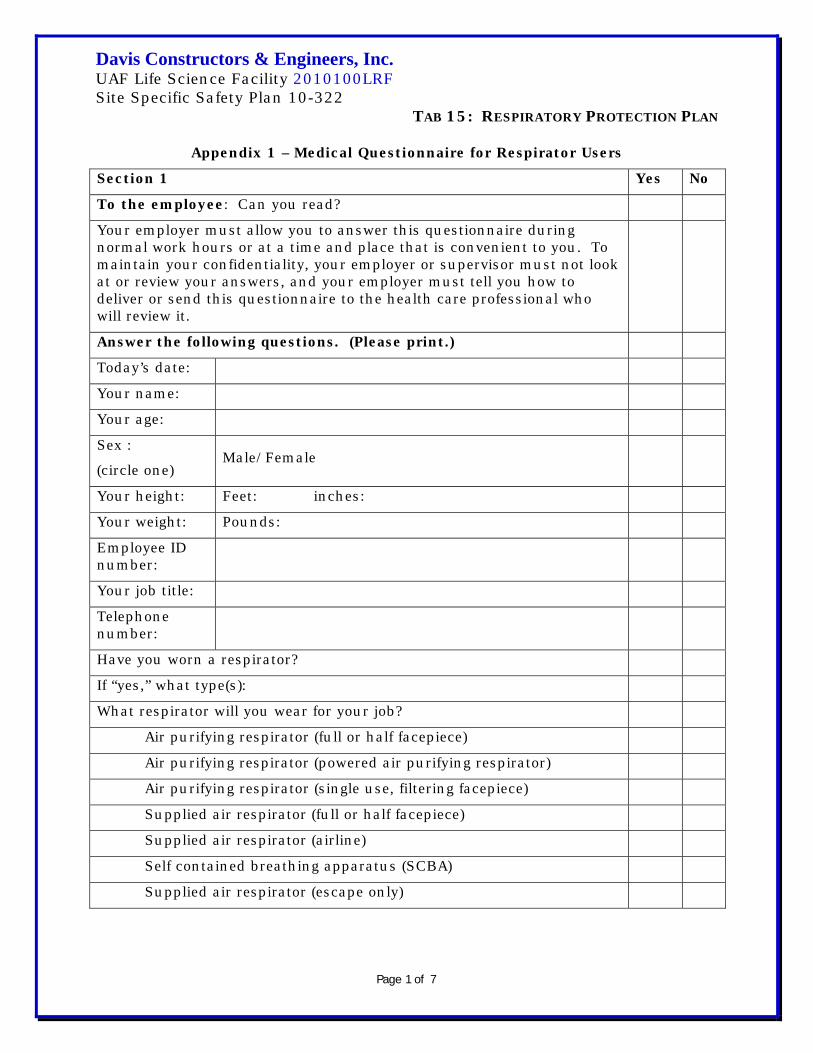
Davis Constructors & Engineers, Inc. UAF Life Science Facility 2010100LRF Site Specific Safety Plan 10-322
TAB 15: RESPIRATORY PROTECTION PLAN
Page 1 of 7
Appendix 1 – Medical Questionnaire for Respirator Users
Section 1 Yes No
To the employee: Can you read?
Your employer must allow you to answer this questionnaire during normal work hours or at a time and place that is convenient to you. To maintain your confidentiality, your employer or supervisor must not look at or review your answers, and your employer must tell you how to deliver or send this questionnaire to the health care professional who will review it.
Answer the following questions. (Please print.)
Today’s date:
Your name:
Your age:
Sex :
(circle one) Male/Female
Your height: Feet: inches:
Your weight: Pounds:
Employee ID number:
Your job title:
Telephone number:
Have you worn a respirator?
If “yes,” what type(s):
What respirator will you wear for your job?
Air purifying respirator (full or half facepiece)
Air purifying respirator (powered air purifying respirator)
Air purifying respirator (single use, filtering facepiece)
Supplied air respirator (full or half facepiece)
Supplied air respirator (airline)
Self contained breathing apparatus (SCBA)
Supplied air respirator (escape only)

Davis Constructors & Engineers, Inc. UAF Life Science Facility 2010100LRF Site Specific Safety Plan 10-322
TAB 15: RESPIRATORY PROTECTION PLAN
Page 2 of 7
Section 2 Yes No 1. Do you currently smoke tobacco or have you smoked in the last
month? If “yes,” explain:
2. Have you ever had any of the following conditions? a. Seizures (fits) b. Diabetes (sugar disease) c. Allergic reactions that interfere with your breathing d. Claustrophobia (fear of closed-in places) e. Trouble smelling odors
3. Have you ever had any of the following pulmonary or lung problems? a. Asbestosis b. Asthma c. Chronic bronchitis d. Emphysema e. Pneumonia f. Tuberculosis g. Silicosis h. Pneumothorax (collapsed lung) i. Lung cancer j. Broken ribs k. Any chest injuries or surgeries l. Any other lung problem that you’ve been told about If “yes,” explain:
4. Do you currently have any of the following symptoms of pulmonary or lung illness?
a. Shortness of breath b. Shortness of breath when walking fast on level ground or walking up
a slight hill or incline
c. Shortness of breath when walking with other people at an ordinary pace on level ground
d. Have to stop for breath when walking at own pace on level ground e. Shortness of breath when washing or dressing yourself f. Shortness of breath that interferes with your job g. Coughing that produces phlegm (thick sputum) h. Coughing that wakes you early in the morning i. Coughing that occurs mostly when you are lying down j. Coughing up blood in the last month k. Wheezing l. Wheezing that interferes with your job
m. Chest pain when you breathe deeply n. Other symptoms that you think may be related to lung problems If “yes,” explain:

Davis Constructors & Engineers, Inc. UAF Life Science Facility 2010100LRF Site Specific Safety Plan 10-322
TAB 15: RESPIRATORY PROTECTION PLAN
Page 3 of 7
5. Have you ever had any of the following cardiovascular or heart
problems?
a. Heart attack b. Stroke c. Angina d. Heart failure e. Swelling in your legs or feet (not caused by walking) f. Heart arrhythmia (heart beating irregularly) g. High blood pressure h. Any other heart problem that you’ve been told about
If “yes,” explain:
6. Have you ever had any of the following cardiovascular or heart symptoms?
a. Frequent pain or tightness in your chest b. Pain or tightness in your chest during physical activity c. Pain or tightness in your chest that interferes with your job d. In the past two years, heart skipped or missed a beat e. Heartburn or indigestion that is not related to eating f. Other symptoms that may relate to heart or circulation problems
If “yes,” explain:
7. Do you currently take medication for any of the following problems? a. Breathing or lung problems b. Heart trouble c. Blood pressure d. Seizures (fits)
If “yes,” explain:
8. If you’ve used a respirator, have you ever had any of the following problems?
a. Eye irritation b. Skin allergies or rashes c. Anxiety d. General weakness or fatigue e. Any other problem that interferes with your use of a respirator

Davis Constructors & Engineers, Inc. UAF Life Science Facility 2010100LRF Site Specific Safety Plan 10-322
TAB 15: RESPIRATORY PROTECTION PLAN
Page 4 of 7
If “yes,” explain:
9. Would you like to talk to the health care professional who will review this questionnaire about your answers to this questionnaire
Yes No
10. Have you ever lost vision in either eye (temporarily or permanently) If “yes,” explain:
11. Do you currently have any of the following vision problems? a. Wear contact lenses? b. Wear glasses? c. Color blind? d. Any other eye or vision problem?
12. Have you ever had an injury to your ears, including a broken ear drum?
If “yes,” explain:
13. Do you currently have any of the following hearing problems? a. Difficulty hearing b. Wear a hearing aid c. Any other hearing or ear problem
If “yes”, explain:
14. Have you ever had a back injury? If “yes”, explain:
15. Do you currently have any of the following musculoskeletal problems?
a. Weakness in any of your arms, hands, legs, or feet b. Back pain c. Difficulty fully moving your arms and legs d. Pain or stiffness when you lean forward or backward at the waist e. Difficulty fully moving your head up or down f. Difficulty fully moving your head side to side g. Difficulty bending at your knees h. Difficulty squatting to the ground i. Climbing a flight of stairs or a ladder carrying more than 25 lbs j. Muscle or skeletal problem that interfere with respirator If “yes”, explain:

Davis Constructors & Engineers, Inc. UAF Life Science Facility 2010100LRF Site Specific Safety Plan 10-322
TAB 15: RESPIRATORY PROTECTION PLAN
Page 5 of 7
Section 3 Yes No 1. In your present job, are you working at high altitudes (over 5,000
feet) or in a place that has lower than normal amounts of oxygen
If "yes," do you have feelings of dizziness, shortness of breath, pounding in your chest, or other symptoms when you're working under these conditions
2. At work or at home, have you ever been exposed to hazardous solvents, hazardous airborne chemicals (e.g., gases, fumes, or dust), or have you come into skin contact with hazardous chemicals
If "yes," name the chemicals if you know them:
3. Have you ever worked with any of the materials, or under any of the conditions, listed below:
a. Asbestos b. Silica (e.g., in sandblasting) c. Tungsten/cobalt (e.g., grinding or welding this material) d. Beryllium e. Aluminum f. Coal (for example, mining) g. Iron h. Tin i. Dusty environments j. Any other hazardous exposures
If "yes," describe these exposures:
4. List any second jobs or side businesses you have:
5. List your previous occupations:
6. List your current and previous hobbies:
7. Have you been in the military services If "yes," were you exposed to biological or chemical agents (either in
training or combat)
8. Have you ever worked on a HAZMAT team 9. Other than medications for breathing and lung problems, heart
trouble, blood pressure, and seizures mentioned earlier in this questionnaire, are you taking any other medications for any reason (including over-the-counter medications)
If "yes," name the medications if you know them:
10. Will you be using any of the following items with your respirator(s) a. HEPA Filters b. Canisters (for example, gas masks) c. Cartridges

Davis Constructors & Engineers, Inc. UAF Life Science Facility 2010100LRF Site Specific Safety Plan 10-322
TAB 15: RESPIRATORY PROTECTION PLAN
Page 6 of 7
11. How often are you expected to use the respirator(s) (circle "yes" or "no" for all answers that apply to you)
a. Escape only (no rescue)
Yes No b. Emergency rescue only c. Less than 5 hours per week d. Less than 2 hours per day e. 2 to 4 hours per day f. Over 4 hours per day
12. During the period you are using the respirator(s), is your work effort a. Light (less than 200 kcal per hour)
If "yes," how long does this period last during the average shift:____________hrs.____________mins. Examples of a light work effort are sitting while writing, typing, drafting, or performing light assembly work; or standing while operating a drill press (1-3 lbs.) or controlling machines.
b. Moderate (200 to 350 kcal per hour) If "yes," how long does this period last during the average
shift:____________hrs.____________mins. Examples of moderate work effort are sitting while nailing or filing; driving a truck or bus in urban traffic; standing while drilling, nailing, performing assembly work, or transferring a moderate load (about 35 lbs.) at trunk level; walking on a level surface about 2 mph or down a 5-degree grade about 3 mph; or pushing a wheelbarrow with a heavy load (about 100 lbs.) on a level surface.
c. Heavy (above 350 kcal per hour) If "yes," how long does this period last during the average
shift:____________hrs.____________mins. Examples of heavy work are lifting a heavy load (about 50 lbs.) from the floor to your waist or shoulder; working on a loading dock; shoveling; standing while bricklaying or chipping castings; walking up an 8-degree grade about 2 mph; climbing stairs with a heavy load (about 50 lbs.).
13. Will you be wearing protective clothing and/or equipment (other than the respirator) when you're using your respirator
If "yes," describe this protective clothing and/or equipment:
14. Will you be working under hot conditions (temperature exceeding 77º F)
15. Will you be working under humid conditions 16. Describe the work you'll be doing while you're using your
respirator(s):
17. Describe any special or hazardous conditions you might encounter

Davis Constructors & Engineers, Inc. UAF Life Science Facility 2010100LRF Site Specific Safety Plan 10-322
TAB 15: RESPIRATORY PROTECTION PLAN
Page 7 of 7
when you're using your respirator(s) (for example, confined spaces, life-threatening gases):
18. Provide the following information, if you know it, for each toxic substance that you'll be exposed to when you're using your respirator(s):
a. Name of the first toxic substance: b. Estimated maximum exposure level per shift: c. Duration of exposure per shift:
Yes No d. Name of the second toxic substance: e. Estimated maximum exposure level per shift: f. Duration of exposure per shift: g. Name of the third toxic substance: h. Estimated maximum exposure level per shift: i. Duration of exposure per shift: j. The name(s) of any other toxic substances that you'll be exposed to
while using your respirator:
19. Describe any special responsibilities you'll have while using your respirator(s) that may affect the safety and well-being of others (for example, rescue, security):

Test Date: Fit Test Expires:
Name: License or SS #
Address:
City: State: Zip:
Respirator Type: 1/2 Face Negative Full-Face Negative PAPR(Circle) Pressure Pressure
Manufacturer: Model Number: Size:
Cartridge Type Tested:
Restrictions:
Type of Test Quantitative Qualitative(Circle) Test Device: Isoamyl Acetate
Saccharin
Bitrex
Results Pass Fail Pass Fail
Test Given By: Test Subject:
Davis Constructors & Engineers Inc.
Appendix 2
Respirator Fit Test Report
Test

Davis Constructors & Engineers, Inc. UAF Life Science Facility 2010100LRF Appendix 3 Site Specific Safety Plan 10-322 TAB 15: RESPIRATORY PROTECTION PLAN
Page 1 of 2
Voluntary Use of Dust Masks This program is designed to protect employee health even though it has been determined that respirators are not required. Filtering face-piece dust masks will be allowed for those employees who wish to use them. This program is designed for compliance with OSHA Standard 29 CFR 1910.134(c)(2)(i) with the exception in 1910.134(c)(2)(ii). The position title has determined that respirators are not required for the following jobs, tasks, or departments:
The use of dust mask respirators by employees is strictly voluntary. The position title will provide and employees are to read Appendix D of the OSHA Respirator Standard 29 CFR 1910.134, a copy of which follows: Appendix D 1910.134 (Non-Mandatory) Information for Employees Using
Respirators When Not Required Under the Standard
Respirators are an effective method of protection against designated hazards when properly selected and worn. Respirator use is encouraged, even when exposures are below the exposure limit, to provide an additional level of comfort and protection for workers. However, if a respirator is used improperly or not kept clean, the respirator itself can become a hazard to the worker. Sometimes, workers may wear respirators to avoid exposures to hazards, even if the amount of hazardous substance does not exceed the limits set by OSHA standards. If your employer provides respirators for your voluntary use, or if you provide your own respirator, you need to take certain precautions to be sure that the respirator itself does not present a hazard. You should do the following: 1. Read and heed all instructions provided by the manufacturer on use,
maintenance, cleaning and care, and warnings regarding the respirators limitations.

Davis Constructors & Engineers, Inc. UAF Life Science Facility 2010100LRF Appendix 3 Site Specific Safety Plan 10-322 TAB 15: RESPIRATORY PROTECTION PLAN
Page 2 of 2
2. Choose respirators certified for use to protect against the contaminant of concern. NIOSH, the National Institute for Occupational Safety and Health of the U.S. Department of Health and Human Services, certifies respirators. A label or statement of certification should appear on the respirator or respirator packaging. It will tell you what the respirator is designed for and how much it will protect you.
3. Do not wear your respirator into atmospheres containing contaminants for
which your respirator is not designed to protect against. For example, a respirator designed to filter dust particles will not protect you against gases, vapors, or very small solid particles of fumes or smoke.
4. Keep track of your respirator so that you do not mistakenly use someone
else’s respirator.

Davis Constructors and Engineers, inc.
Jobsite: UAF Life Science Facility Date:10-322 Time:Instructor:
*Signing this form is acknowledging you've received DCE Respiratory Protection Plan and understand the procedures and equipment discussed as noted below.
Name Signature
Donning respirator and user seal check
Fit testing procedure - Qualatitive Test
Appendix 4 Tab 15: Respiratory Protection Plan
Respirator inspection, components, and care
Respirator limitations and cautions
Use of adminisrative and engineering controls
Hazards and exposure levels
Respirator cartridges and filters selection
Respiratory Equipment and Training
ATTENDEES:
Items DiscussedDavis Constructors and Engineers Respiratory Protection Program
Medical requirements

Davis Constructors & Engineers, Inc. UAF Life Science Facility 2010100LRF Site Specific Safety Plan 10-322 TAB 16: INDOOR AIR QUALITY CONTROLS
Page 1 of 7
Indoor Air Quality Controls Source: Providence Alaska Medical Center
In case of need for work associated with Virology Building or commissioning and startup of laboratory or other critical areas of the Life Science Facility-- may be amended or replaced as necessary
Part 1 General 1.1 Section Includes: A. Construction procedures to promote adequate indoor air quality after construction. B. Building flush-out after construction and before occupancy. C. Testing indoor air quality before commencement of construction; existing building areas only. D. Testing indoor air quality after completion of construction. 1.2 Project Goals A. See Section 013515, LEED Certification Procedures for overall project goals relating to environment and energy. B. Dust and Airborne Particulates: Prevent deposition of dust and other particulates in HVAC ducts and equipment. 1. Cleaning of ductwork is not contemplated under this contract. 2. Contractor shall bear the cost of cleaning required due to failure to protect ducts and equipment from construction dust. C. Airborne Contaminants: Procedures and products have been specified to minimize indoor air pollutants. 1. Furnish products meeting the specifications. 2. Avoid construction practices that could result in contamination of installed products leading to indoor air pollution. D. Ventilation: HVAC system has been designed to achieve the minimum requirements for ventilation specified in ASHRAE 62.1. 1.3 Related Requirements A. Section 013515, LEED Certification Procedures: LEED credits relating to indoor air quality. B. Section 014000, Quality Requirements: Testing and inspection services.

Davis Constructors & Engineers, Inc. UAF Life Science Facility 2010100LRF Site Specific Safety Plan 10-322 TAB 16: INDOOR AIR QUALITY CONTROLS
Page 2 of 7
C. Section 016116, Volatile Organic Compound (VOC) Content Restrictions. D. Section 234000, HVAC Air Cleaning Devices: HVAC filters. E. Section 230593, Testing, Adjusting, and Balancing for HVAC: Testing HVAC systems for proper air flow rates, adjustment of dampers and registers, and setting for equipment. 1.4 Reference Standards A. ASHRAE Std. 52.2, Method of Testing General Ventilation Air- cleaning devices for removal efficiency by particle. B. ASHRAE Std. 62.1, Ventilation for Acceptable Indoor Air Quality; 2007 (errata 2008). C. SMACNA (OCC), IAQ Guideline for Occupied Buildings Under Construction; 207. 1.5 Definitions A. Adsorptive Materials: Gypsum board, acoustical ceiling tile and panels, carpet and carpet tile, fabrics, fibrous insulation, and other similar products. B. Contaminants: Gases, vapors, regulated pollutants, airborne mold and mildew and the like, as specified. C. Particulates: Dust, dirt, and other airborne solid matter. D. Wet Work: Concrete, plaster, gypsum board joint compound, coatings, and other products that emit water vapor or volatile organic compounds during installation, drying, or curing. 1.6 Submittals A. See Section 013000, Administrative Requirements for submittal procedures. B. Indoor Air Quality Management Plan: Describe in detail measures to be taken to promote adequate indoor air quality upon completion; use SMACNA IAQ Guidelines for Occupied Buildings Under Construction as a guide. 1. Submit not less than 60 days before enclosure of building. 2. Identify potential sources of odor and dust. 3. Identify construction activities likely to produce odor or dust. 4. Identify areas of project potentially affected, especially occupied areas.

Davis Constructors & Engineers, Inc. UAF Life Science Facility 2010100LRF Site Specific Safety Plan 10-322 TAB 16: INDOOR AIR QUALITY CONTROLS
Page 3 of 7
5. Evaluate potential problems by severity and describe methods of control. 6. Describe construction ventilation to be provided including type and duration of ventilation, use of permanent HVAC systems, types of filters and schedule for replacement of filters. 7. Describe cleaning and dust control procedures. 8. Describe coordination with commissioning procedures. C. Interior Finishes Installation Schedule: Identify each interior finish that either generates odors, moisture, or vapors or is susceptible to adsorption of odors and vapors, and indicate air handling zone, sequence of application, and curing times. D. Duct and Terminal Unit Inspection Report. E. Air Contaminant Test Plan: Identify: 1. Testing agency qualifications. 2. Locations and scheduling of air sampling. 3. Test procedures in detail. 4. Test instruments and apparatus. 5. Sampling methods. F. Air Contaminant Test Reports: Show: 1. Location where each sample was taken and time. 2. Test values for each air sample; average the values of each set of 3. 3. HVAC operating conditions. 4. Certification of test equipment calibration. 5. Other conditions or discrepancies that might have influenced results. G. Ventilation Effectiveness Test Plan: Identify: 1. Testing agency qualifications. 2. Description of test spaces including locations of air sampling. 3. Test procedures in detail; state whether tracer gas decay or step-up will be used. 4. Test instruments and apparatus; identify tracer gas to be used. 5. Sampling methods. H. Ventilation Effectiveness Test Reports: Show: 1. Include preliminary tests of instruments and apparatus and of test spaces. 2. Calculation of ventilation effectiveness, E. 3. Location where each sample was taken and time. 4. Test values for each air sample. 5. HVAC operating conditions.
Davis Constructors & Engineers, Inc. UAF Life Science Facility 2010100LRF Site Specific Safety Plan 10-322 TAB 16: INDOOR AIR QUALITY CONTROLS
Page 4 of 7
6. Other information specified in ASHRAE 129. 7. Other conditions or discrepancies that might have influences results. 1.7 Quality Assurance A. Testing and Inspection Agency Qualifications: Independent testing agency having minimum of five years experience in performing the types of testing specified. Part 2 Products 2.1 Materials A. Low VOC Materials: See Section 016116. B. Auxiliary Air Filters: MERV 14 when tested in accordance with ASHRAE 52.2. Part 3 Execution 3.1 Construction Procedures A. Prevent the absorption of moisture and humidity by adsorptive materials by: 1. Sequencing the delivery of such materials so they are not present in the building until wet work is completed and dry. 2. Delivery and storage of such materials in fully sealed moisture- impermeable packaging. 3. Provide sufficient ventilation for drying within reasonable time frame. B. Begin construction ventilation when building is substantially enclosed. C. If extremely dusty or dirty work must be conducted inside the building, shut down HVAC systems for the duration; remove dust and dirt completely before restarting systems. D. When working in a portion of an occupied building prevent movement of air from construction area to occupied area. E. HVAC equipment and supply air ductwork may be used for ventilation during construction: 1. Operate HVAC system on 100 percent outside air with 1.5 air changes per hour, minimum, or as required for adjacent occupied spaces outside construction areas as applicable.

Davis Constructors & Engineers, Inc. UAF Life Science Facility 2010100LRF Site Specific Safety Plan 10-322 TAB 16: INDOOR AIR QUALITY CONTROLS
Page 5 of 7
2. Ensure that air filters are correctly installed prior to starting use; replace filters when they lose efficiency. 3. Do not use return-air ductwork for ventilation. 4. Seal return air inlets or otherwise positively isolate return air system to prevent recirculation of air; provide alternate return- air pathways. F. Do not store construction materials or waste in mechanical or electrical rooms. G. Prior to use of return-air ductwork without intake filters clean up and remove dust and debris generated by construction activities. 1. Inspect duct intakes, return-air grilles, and terminal units for dust. 2. Clean plenum spaces including top sides of lay-in ceilings, outsides of ducts, tops of pipes and conduit. 3. Clean tops of doors and frames. 4. Clean mechanical and electrical rooms including tops of pipes, ducts, and conduit, equipment, and supports. 5. Clean return plenums of air handling units. 6. Remove intake filters last after cleaning is complete. H. Do not perform dusty or dirty work after starting use of return-air ducts without intake filters. I. Use other relevant recommendations of SMACNA IAQ Guideline for Occupied Buildings Under Construction for avoiding unnecessary contamination due to construction procedures. 3.2 Building Flush-out A. Contractor’s Option: Either full continuous flush-out or satisfactory air contaminant testing is required, not both. B. Perform building flush-out before occupancy. C. Do not start flush-out until: 1. All construction is complete. 2. HVAC systems have been tested, adjusted, and balanced for proper operation. 3. Inspection of inside of return air ducts and terminal units confirms that cleaning is not necessary. 4. New HVAC filtration media has been installed. D. Building Flush-out: Operate all ventilation systems at normal flow rates with 100 percent outside air until a total air volume of 14,000 cubic feet per square foot of floor area has been supplied.

Davis Constructors & Engineers, Inc. UAF Life Science Facility 2010100LRF Site Specific Safety Plan 10-322 TAB 16: INDOOR AIR QUALITY CONTROLS
Page 6 of 7
1. Obtain Owner’s concurrence that construction is complete enough before beginning flush-out. 2. Maintain interior temperature of at least 60 degrees F and interior relative humidity no higher than 60 percent. 3. If additional construction involving materials that produce particulates or any of the specified contaminants is conducted during flush-out, start flush-out over. 4. If interior spaces must be occupied prior to completion of the flush-out, supply a minimum of 25 percent of the total air volume prior to occupancy and: a. begin ventilation at least three hours prior to daily occupancy. b. continue ventilation during all occupied periods. c. provide minimum outside air volume of 0.30 cfm per square foot or design minimum outside air rate, whichever is greater. E. Install new HVAC filtration media after completion of flush-out and before occupancy or further testing. 3.3 Air Contaminant Testing A. Contractor’s Option: Either full continuous flush-out or further testing. B. Perform air contaminant testing before starting construction as base line for evaluation of post-construction testing. C. Perform air contaminant testing before occupancy. D. Do not start air contaminant testing until: 1. All construction is complete including interior finishes. 2. HVAC systems have been tested, adjusted, and balanced for proper operation. 3. New HVAC filtration media have been installed. E. Indoor Air Samples: Collect from spaces representative of occupied areas: 1. Collect samples while operable windows and exterior doors are closed, HVAC system is running normally as if occupied with design minimum outdoor air, but with the building unoccupied. 2. Collect samples from spaces in each contiguous floor area in each air handler zone, but not less than one sample per 12,000 square feet; take samples from areas having the least ventilation and those having the greatest presume source strength.

Davis Constructors & Engineers, Inc. UAF Life Science Facility 2010100LRF Site Specific Safety Plan 10-322 TAB 16: INDOOR AIR QUALITY CONTROLS
Page 7 of 7
3. Collect samples from height from 36″ to 72″ above floor. 4. Collect samples from same locations on 3 consecutive days during normal business hours; average the results of each set of 3 samples. 5. When retesting the same building areas take samples from at least the same locations as in the first test. F. Outdoor Air Samples: Collect samples at outside air intake of each air handler at the same time as indoor samples are taken. G. Analyze air samples and submit report to Owner. H. Air Contaminant Concentration Determination and Limits: 1. Carbon Monoxide: Not more than 9 parts per million and not more than 2 parts per million higher than outside air. 2. Carbon Dioxide: Measure in ppm, in relation to outdoor air; not more than 700 ppm higher than outdoor air. 3. Airborne Mold and Mildew: Measure in relation to outside air; not higher than outside air. 4. Formaldehyde: Measure in micrograms per cubic meter, in relation to outside air, not more than 20 micrograms per cubic meter higher than outside air. 5. Total Volatile Organic Compounds (TVOC): Measure in micrograms per cubic meter in relation to outside air, not more than 200 micrograms per cubic meter higher than outside air. 6. 4-Phenylcyclohexene (4-PC): Measure in micrograms per cubic meter in relation to outside air; not more than 50 micrograms per cubic meter. 7. Particulates (PM10): Not more than 50 micrograms per cubic meter. 8. Total Particulates (PM): Measure in micrograms per cubic meter in relation to outside air; not more than 20 micrograms per cubic meter higher than outside air. 9. Regulated Pollutants: Measure in relation to outside air; not more than contained in outside air. I. If air samples show concentrations higher than those specified, ventilate with 100 percent outside air and retest at no cost to Owner, or conduct full building flush-out specified above.

Davis Constructors & Engineers, Inc. UAF Life Science Facility 2010100LRF Site Specific Safety Plan 10-322 TAB 17: ELECTRICAL SAFETY PROGRAM
Page 1 of 2
Electrical Safety Program Purpose: To prevent injury to employees due to the inadvertent contact with energized tools and cords. To ensure a system that will de-energize electrical equipment before it can create a danger to employees. Background: This policy and procedure has been promulgated to ensure compliance with OSHA (federal/state) regulations and to provide a safe and healthful work place. Responsibility: All supervisors and employees of Davis are required to comply fully with this policy and procedure. Failure to do so will result in disciplinary action up to and including termination of employment. Definitions: A Ground-Fault Circuit Interrupter is a device for the protection of personnel that functions to de-energize a circuit or portion thereof within an established period of time when a current to ground exceeds some predetermined value that is less than that required to operate the overcurrent protective device of the supply circuit. Procedures: This ground- fault circuit interrupter procedure shall meet the requirements set forth in Safety Standards for Construction Work.
1. Visual inspection of all electrical cords will be the responsibility of the user at the start of each workday. If the cord shows signs of wear and/or fraying, missing pins, etc, it shall be immediately removed from service, tagged with a “DO NOT USE” notice and brought to the attention of a supervisor and/or the Project Safety Manager.
2. Visual inspection of all power tools prior to use and at the start of each
workday shall be the responsibility of the tool operator. If the tool shows signs of cord-plug separation, pins missing, etc., it must be removed from service, and tagged with a “DO NOT USE” notice until it has been repaired by a person qualified to make such repairs. The condition of the tool should be brought to the attention of a supervisor and/or the Project Safety Manager.

Davis Constructors & Engineers, Inc. UAF Life Science Facility 2010100LRF Site Specific Safety Plan 10-322 TAB 17: ELECTRICAL SAFETY PROGRAM
Page 2 of 2
3. A Davis supervisor or Project Safety Manager shall perform testing of all temporary power boxes at least monthly. Use of approved circuit testing equipment such as the Greenlee or Unitest GFI circuit tester is required. Results of such tests will be documented and maintained in the project office. If results show a temporary power box is malfunctioning, the box shall be immediately removed from service and replaced with an operable power box. The disabled power box will be marked with a “DO NOT USE” tag and appropriate supervisors shall be advised of the condition of the power box.
4. All 120-volt, single phase, 15 and 20-ampere receptacle outlets on Davis
projects, which are in use by Davis employees or subcontractors, must have approved ground- fault circuit interrupters for personnel protection.

Davis Constructors & Engineers, Inc. UAF Life Science Facility 2010100LRF Site Specific Safety Plan 10-322 TAB 18: SCAFFOLD SAFETY PROGRAM
Page 1 of 16
Scaffold Safety Program Purpose: To set forth rules and regulations giving direction in the building of scaffolds that not only meet Federal and State OSHA regulations but also provides a safe access and work area for Davis employees. Background: Falls from scaffolds account for a large number of injuries and deaths in the construction industry each year. It’s the goal of Davis to eliminate these hazards from our projects. Procedure: Each scaffold must be inspected prior to initial use and after alteration or moving by a competent person. There is no such thing as a temporary scaffold. All scaffolding must be erected and maintained to conform to established standards (OSHA (Federal/State). The following guidelines should be used to ensure compliance with the regulatory requirements. Capacity:
• Each scaffold and scaffold component is capable of supporting, without failure, its own weight and at least 4 times the maximum intended load applied or transmitted to it.
• Each suspension rope, including connecting hardware, used on adjustable suspension scaffolds is capable of supporting, without failure, at least 6 times the maximum intended load applied or transmitted to that rope with the scaffold operating at either the rated load of the hoist, or 2 (minimum) times the stall load of the hoist, whichever is greater.
• Scaffolds are designed by a qualified person and are constructed and loaded in accordance with that design.
Scaffold platform construction:
1. Each platform on all working levels of scaffolds are fully planked or decked between the front uprights and the guardrail supports as follows: • Each platform unit (e.g., scaffold plank, fabricated plank, fabricated
deck, or fabricated platform) is installed so the space between adjacent units and the space between the platform and the uprights is no more than 1 inch (2.5 cm) wide, except where a wider space is necessary (for example, to fit around uprights when side brackets are used to extend the width of the platform).
Davis Constructors & Engineers, Inc. UAF Life Science Facility 2010100LRF Site Specific Safety Plan 10-322 TAB 18: SCAFFOLD SAFETY PROGRAM
Page 2 of 16
• The platform is planked or decked as fully as possible and the remaining open space between the platform and the uprights does not exceed 9 ½ inches (24.1 cm).
• Each scaffold platform and walkway is at least 18 inches (46 cm) wide.
• Each ladder jack scaffold, top plate bracket scaffold, roof bracket scaffold, and pump jack scaffold is at least 12 inches (30 cm) wide. There is no minimum width requirement for boatswains' chairs.
• Where scaffolds must be used in areas that are so narrow that platforms and walkways cannot be at least 18 inches (46 cm) wide, platforms and walkways are as wide as feasible, and employees protected from fall hazards by the use of guardrails and/or personal fall arrest systems.
2. The front edge of all platforms are not more than 14 inches (36 cm) from
the face of the work, unless guardrail systems are erected along the front edge and/or personal fall arrest systems are used to protect employees from falling.
3. The maximum distance from the face for outrigger scaffolds is 3 inches (8
cm); 4. The maximum distance from the face for plastering and lathing
operations shall be 18 inches (46 cm). 5. Each end of a platform (unless cleared or otherwise restrained by hooks
or equivalent means) extends over the centerline of its support at least 6 inches (15 cm).
6. Each end of a platform 10 feet or less in length does not extend over its
support more than 12 inches (30 cm) unless the platform is designed and installed so that the cantilevered portion of the platform is able to support employees and/or materials without tipping, or has guardrails which block employee access to the cantilevered end.
7. Each platform greater than 10 feet in length does not extend over its
support more than 18 inches (46 cm), unless it is designed and installed so that the cantilevered portion of the platform is able to support employees without tipping, or has guardrails which block employee access to the cantilevered end.
8. On scaffolds where scaffold planks are abutted to create a long platform,
each abutted end rests on a separate support surface. This provision does not preclude the use of common support members, such as “T”

Davis Constructors & Engineers, Inc. UAF Life Science Facility 2010100LRF Site Specific Safety Plan 10-322 TAB 18: SCAFFOLD SAFETY PROGRAM
Page 3 of 16
sections, to support abutting planks, or hook on platforms designed to rest on common supports.
9. On scaffolds where platforms are overlapped to create a long platform,
the overlap does occur only over supports, and is not less than 12 inches (30 cm) unless the platforms are nailed together or otherwise restrained to prevent movement.
10. At all points of a scaffold where the platform changes direction, such as
turning a corner, any platform resting on a bearer at an angle other than a right angle is laid first, and platforms which rest at right angles over the same bearer are laid second, on top of the first platform.
11. Wood platforms are not covered with opaque finishes, except that
platform edges may be covered or marked for identification. Platforms may be coated periodically with wood preservatives, fire-retardant finishes, and slip-resistant finishes; however, the coating may not obscure the top or bottom wood surfaces.
12. Scaffold components manufactured by different manufacturers are not
intermixed unless the components fit together without force and the scaffold’s structural integrity is maintained by the user. Scaffold components manufactured by different manufacturers are not be modified in order to intermix them unless a competent person determines the resulting scaffold is structurally sound.
13. Scaffold components made of dissimilar metals are not used together
unless a competent person has determined that galvanic action will not reduce the strength of any component.
Criteria for supported scaffolds:
1. Supported scaffolds with a height to base width (including outrigger supports, if used) ratio of more than four to one (4:1) are restrained from tipping by guying, tying, bracing, or equivalent means, as follows: • Guys, ties, and braces are installed at locations where horizontal
members support both inner and outer legs. • Guys, ties, and braces are installed according to the scaffold
manufacturer’s recommendations or at the closest horizontal member to the 4:1 height and be repeated vertically at locations of horizontal members every 20 feet (6.1 m) or less thereafter for scaffolds 3 feet (0.91 m) wide or less, and every 26 feet (7.9 m) or less thereafter for scaffolds greater than 3 feet (0.91 m) wide. The top guy, tie or brace of completed scaffolds shall be placed no further than the 4:1 height from the top. Such guys, ties and braces shall be installed at each

Davis Constructors & Engineers, Inc. UAF Life Science Facility 2010100LRF Site Specific Safety Plan 10-322 TAB 18: SCAFFOLD SAFETY PROGRAM
Page 4 of 16
end of the scaffold and at horizontal intervals not to exceed 30 feet (9.1 m) (measured from one end [not both] towards the other).
• Ties, guys, braces, or outriggers are used to prevent the tipping of supported scaffolds in all circumstances where an eccentric load, such as a cantilevered work platform, is applied or is transmitted to the scaffold.
2. Supported scaffold poles, legs, posts, frames, and uprights bear on base
plates and mudsills or other adequate firm foundation.
3. Footings are level, sound, rigid, and capable of supporting the loaded scaffold without settling or displacement.
4. Unstable objects are not used to support scaffolds or platform units.
5. Unstable objects are not used as working platforms.
6. Front-end loaders and similar pieces of equipment are not used to support scaffold platforms unless the manufacturer for such use has specifically designed them.
7. Forklifts are not used to support scaffold platforms unless the entire platform is attached to the fork and the forklift is not moved horizontally while the platform is occupied and meets the following criteria: The platform has been manufactured and supplied by the manufacturer of the forklift and is machine specific, or the platform is constructed per the design of a registered professional engineer experienced in such designs. Said design must specify as a minimum that the overall width of the platform does not extend more than 9 inches beyond the stabilized width of the forklift (extended stabilizers for machines so equipped or the outside dimension of the front tire spread for machines not equipped with stabilizers); the weight of the platform and its maximum intended load multiplied by a factor of 4, do not exceed the capacity of the machine at its maximum extension. In addition, workers may not ride on the platform except during raising and lowering operation.
8. Supported scaffold poles, legs, posts, frames, and uprights are plumb and braced to prevent swaying and displacement.
Criteria for suspension scaffolds: 1. All suspension scaffold support devices, such as outrigger beams,
cornice hooks, parapet clamps, and similar devices, rest on surfaces capable of supporting at least 4 times the load imposed on them by the
Davis Constructors & Engineers, Inc. UAF Life Science Facility 2010100LRF Site Specific Safety Plan 10-322 TAB 18: SCAFFOLD SAFETY PROGRAM
Page 5 of 16
scaffold operating at the rated load of the hoist (or at least 1.5 times the load imposed on them by the scaffold at the stall capacity of the hoist, whichever is greater).
2. Suspension scaffold outrigger beams, when used, are made of structural
metal or equivalent strength material, and are restrained to prevent movement.
3. The inboard ends of suspension scaffold outrigger beams are stabilized
by bolts or other direct connections to the floor or roof deck, or they have their inboard ends stabilized by counterweights, except masons’ multi-point adjustable suspension scaffold outrigger beams are not stabilized by counterweights.
4. Before the scaffold is used, direct connections are evaluated by a
competent person who confirms, based on the evaluation, that the supporting surfaces are capable of supporting the loads to be imposed. In addition, an engineer experienced in such scaffold design designs masons’ multi-point adjustable suspension scaffold connections.
5. Counterweights are made of non-flowable material. Sand, gravel and
similar materials that can be easily dislocated are not used as counterweights.
6. Only those items specifically designed, as counterweights are used to
counterweight scaffold systems. Construction materials such as, but not limited to, masonry units and rolls of roofing felt, are not used as counterweights.
7. Counterweights are secured by mechanical means to the outrigger beams
to prevent accidental displacement. 8. Counterweights are not removed from an outrigger beam until the
scaffold is disassembled. 9. Outrigger beams, which are not stabilized by bolts or other direct
connections to the floor or roof deck, are secured by tiebacks.
10. Tiebacks are equivalent in strength to the suspension ropes. 11. Outrigger beams are placed perpendicular to its bearing support (usually
the face of the building or structure). However, where the employer can demonstrate it’s not possible to place an outrigger beam perpendicular to the face of the building or structure because of obstructions that cannot

Davis Constructors & Engineers, Inc. UAF Life Science Facility 2010100LRF Site Specific Safety Plan 10-322 TAB 18: SCAFFOLD SAFETY PROGRAM
Page 6 of 16
be moved, the outrigger beam may be placed at some other angle, provided opposing angle tiebacks are used.
12. Tiebacks are secured to a structurally sound anchorage on the building
or structure. Sound anchorages include structural members, but do not include standpipes, vents, other piping systems, or electrical conduit.
13. Tiebacks are installed perpendicular to the face of the building or
structure, or opposing angle tiebacks shall be installed. Single tiebacks installed at an angle are prohibited.
14. Suspension scaffold outrigger beams are:
• Provided with stop bolts or shackles at both ends; • Securely fastened together with the flanges turned out when channel
iron beams are used in place of I-beams; • Installed with all bearing supports perpendicular to the beam center
line; • Set and maintained with the web in a vertical position; and
15. When an outrigger beam is used, the shackle or clevis with which the
rope is attached to the outrigger beam and placed directly over the centerline of the stirrup.
16. Suspension scaffold support devices such as cornice hooks, roof hooks,
roof irons, parapet clamps, or similar devices shall be: • Made of steel, wrought iron, or materials of equivalent strength • Supported by beating blocks; and • Secured against movement by tiebacks installed at right angles to the
face of the building or structure, or opposing angle tiebacks are installed and secured to a structurally sound point of anchorage on the building or structure. Sound points of anchorage include structural members, but do not include standpipes, vents, other piping systems, or electrical conduit.
• Tiebacks are equivalent in strength to the hoisting rope.
17. When winding drum hoists are used on a suspension scaffold, they contain not less than four wraps of the suspension rope at the lowest point of scaffold travel. When other types of hoists are used, the suspension ropes are long enough to allow the scaffold to be lowered to the level below without the rope end passing through the hoist, or the rope end is configured or provided with means to prevent the end from passing through the hoist.
18. The use of repaired wire rope as suspension rope is prohibited.

Davis Constructors & Engineers, Inc. UAF Life Science Facility 2010100LRF Site Specific Safety Plan 10-322 TAB 18: SCAFFOLD SAFETY PROGRAM
Page 7 of 16
19. Wire suspension ropes are not joined together except through the use of
eye splice thimbles connected with shackles or coverplates and bolts. 20. The load end of wire suspension ropes are equipped with proper size
thimbles and secured by eyesplicing or equivalent means. 21. A competent person, prior to each work shift, inspects ropes for defects
and after every occurrence which could affect a rope’s integrity. Ropes are replaced if any of the following conditions exist: • Any physical damage that impairs the function and strength of the
rope. • Kinks that might impair the tracking or wrapping of rope around the
drum(s) or sheave(s). • Six randomly distributed broken wires in one rope lay or three broken
wires in one strand in one rope lay. • Abrasion, corrosion, scrubbing, flattening or peening causing loss of
more than one-third of the original diameter of the outside wires. • Heat damage caused by a torch or any damage caused by contact
with electrical wires. • Evidence that the secondary brake has been activated during an
overspeed condition and has engaged the suspension rope.
22. Swaged attachments or spliced eyes on wire suspension ropes are not used unless the wire rope manufacturer or a qualified person makes them.
23. When wire rope clips are used on suspension scaffolds:
• There is a minimum of 3 wire rope clips installed, with the clips a minimum of 6 rope diameters apart
• Clips are installed according to the manufacturer’s recommendations; • Clips are retightened to the manufacturer’s recommendations after
the initial loading; • Clips are inspected and retightened to the manufacturer’s
recommendations at the start of each work shift thereafter • U-bolt clips are not used at the point of suspension for any scaffold
hoist; • When U-bolt clips are used, the U-bolt is placed over the dead end of
the rope, and the saddle is placed over the live end of the rope.
24. A qualified testing laboratory tests suspension scaffold power-operated hoists and manual hoists.

Davis Constructors & Engineers, Inc. UAF Life Science Facility 2010100LRF Site Specific Safety Plan 10-322 TAB 18: SCAFFOLD SAFETY PROGRAM
Page 8 of 16
25. Gasoline-powered equipment and hoists are not used on suspension scaffolds.
26. Gears and brakes of power-operated hoists used on suspension scaffolds
are enclosed. 27. In addition to the normal operating brake, suspension scaffold power-
operated hoists and manually operated hoists have a braking device or locking pawl which engages automatically when a hoist makes either of the following uncontrolled movements: an instantaneous change in momentum or an accelerated overspeed.
28. Manually operated hoists require a positive crank force to descend. 29. Two-point and multi-point suspension scaffolds are tied or otherwise
secured to prevent them from swaying, as determined to be necessary based on an evaluation by a competent person. Window clearers’ anchors shall not be used for this purpose.
30. Devices whose sole function is to provide emergency escape and rescue
are not used as working platforms. This provision does not preclude the use of systems, which are designed to function both as suspension scaffolds and emergency systems.
Access
1. When scaffold platforms are more than 2 feet (0.6 m) above or below a point of access, portable ladders, hook-on ladders, attachable ladders, stair towers (scaffold stairways/towers), stairway-type ladders (such as ladder stands), ramps, walkways, integral prefabricated scaffold access, or direct access from another scaffold, structure, personnel hoist, or similar surface are used. Crossbraces are not used as a means of access.
2. Portable, hook-on, aid attachable ladders are positioned so as not to tip
the scaffold, 3. Hook-on and attachable ladders are positioned so that their bottom rung
is not more than 24 inches (61 cm) above the scaffold supporting level. • When hook-on and attachable ladders are used on a supported
scaffold more than 35 feet (10.7 m) high, they have rest platforms at 35-foot (10.7 m) maximum vertical intervals.
• Hook-on and attachable ladders are specifically designed for use with the type of scaffold used,

Davis Constructors & Engineers, Inc. UAF Life Science Facility 2010100LRF Site Specific Safety Plan 10-322 TAB 18: SCAFFOLD SAFETY PROGRAM
Page 9 of 16
• Hook-on and attachable ladders have a minimum rung length of 11¼ inches (29 cm); and
• Hook-on and attachable ladders have uniformly spaced rungs with a maximum spacing between rungs of l6 ¾ inches.
4. Stairway-type ladders:
• Are positioned such that their bottom step is not more than 24 inches (61 cm) above the scaffold supporting level;
• Are provided with rest platforms at 12 foot (3.7 m) maximum vertical intervals;
• Have a minimum step width of 16 inches (41 cm), except that mobile scaffold stairway-type ladders have a minimum step width of 11½ inches (30 cm); and
• Have slip-resistant treads on all steps and landings. 5. Scaffold stairway/towers:
• Are positioned such that their bottom step is not more than 24 inches (61 cm.) above the scaffold supporting level.
• A stair rail consisting of a top rail and a midrail are provided on each side of each scaffold stairway.
• The toprail of each stair rail system is also capable of serving as a handrail, unless a separate handrail is provided.
• Handrails, and toprails that serve as handrails, provides an adequate handhold for employees grasping them to avoid falling.
• Stair rail systems and handrails are surfaced to prevent injury to employees from punctures or lacerations, and to prevent snagging of clothing.
• The ends of stair rail systems and handrails are constructed so they do not constitute a projection hazard.
• Handrails and toprails used as handrails are at least 3 inches (7.6 cm) from other objects.
• Stair rails are not less than 28 inches (71 cm) nor more than 37 inches (94 cm) from the upper surface of the stair rail to the surface of the tread, in line with the face of the riser at the forward edge of the tread.
• A landing platform at least 18 inches (45.7 cm) wide by at least 18 inches (45.7 cm) long is provided at each level.
• Each scaffold stairway is at least 18 inches (45.7 cm) wide between stair rails.
• Treads and landings have slip-resistant surfaces. • Stairways are installed between 40 degrees and 60 degrees from the
horizontal.

Davis Constructors & Engineers, Inc. UAF Life Science Facility 2010100LRF Site Specific Safety Plan 10-322 TAB 18: SCAFFOLD SAFETY PROGRAM
Page 10 of 16
• Guardrails meeting the requirements of paragraph (g)(4) of this section shall be provided on the open sides and ends of each landing.
• Riser height shall be uniform, within ¼ inch, (0.6 cm) for each flight of stairs. Greater variations in riser height are allowed for the top and bottom steps of the entire system, not for each flight of stairs.
• Tread depth shall be uniform, within ¼ inch, for each flight of stairs. 6. Ramps and walkways:
• 6 feet (1.8 m) or more above lower levels have guardrail systems which comply with subpart M—Fall Protection.
• No ramp or walkway is inclined more than a slope of one (1) vertical to three (3) horizontal (20 degrees above the horizontal).
• If the slope of a ramp or a walkway is steeper than one (1) vertical in eight (8) horizontal, the ramp or walkway has cleats not more than fourteen (14) inches (35 cm) apart which are securely fastened to the planks to provide footing.
7. Integral prefabricated scaffold access frames:
• Are specifically designed and constructed for use as ladder rungs; • Have a rung length of at least 8 inches (20 cm); • Are not used as work platforms when rungs are less than 11½ inches
in length, unless each affected employee uses fall protection, or a positioning device, which complies with §1926.502;
• Are uniformly spaced within each frame section; • Are provided with rest platforms at 35-foot (10.7 m) maximum vertical
intervals on all supported scaffolds more than 35 feet (10.7 m) high; and
• Have a maximum spacing between rungs of 16 ¾ inches (43 cm). Non-uniform rung spacing caused by joining end frames together is allowed, provided the resulting spacing does not exceed 16 ¾ inches (43 cm).
• Steps and rungs of ladder and stairway type access line up vertically with each other between rest platforms.
• Direct access to or from another surface is used only when the scaffold is not more than 14 inches (36 cm) horizontally and not more than 24 inches (61 cm) vertically from the other surface.
• Effective September 2, 1997, access for employees erecting or dismantling supported scaffolds shall be in accordance with the following:
• The employer provides safe means of access for each employee erecting or dismantling a scaffold where the provision of safe access is feasible and does not create a greater hazard. The employer has a competent person determine whether it's feasible or would pose a greater hazard to provide, and have employees use a safe means of

Davis Constructors & Engineers, Inc. UAF Life Science Facility 2010100LRF Site Specific Safety Plan 10-322 TAB 18: SCAFFOLD SAFETY PROGRAM
Page 11 of 16
access. This determination is based on site conditions and the type of scaffold being erected or dismantled.
• Hook-on or attachable ladders are installed as soon as scaffold erection has progressed to a point that permits safe installation and use.
• When erecting or dismantling tubular welded frame scaffolds, (end) frames, with horizontal members that are parallel, level and are not more than 22 inches apart vertically may be used as climbing devices for access, provided they are erected in a manner that creates a usable ladder and provides good hand hold and foot space.
• Cross-braces on tubular welded frame scaffolds are not used as a means of access or egress.
Use
1. Scaffolds and scaffold components are not loaded in excess of their maximum intended loads or rated capacities, whichever is less.
2. The use of shore or lean-to scaffolds is prohibited. 3. A competent person (before each work shift) inspects scaffolds and
scaffold components for visible defects, and after any occurrence which could affect a scaffolds structural integrity.
4. Any part of a scaffold damaged or weakened such that its strength is less
than that required by paragraph (a) of this section is immediately repaired or replaced, braced to meet those provisions, or removed from service until repaired.
5. Scaffolds are not moved horizontally while employees are on them,
unless a registered professional engineer specifically for such movement or, for mobile scaffolds has designed them, where the provisions of § 1926.452(w) are followed.
6. Scaffolds are not erected, used, dismantled, altered, or moved such that
they or any conductive material handled on them might come closer to exposed and energized power lines.
7. Scaffolds and materials may be closer to power lines than specified above
where such clearance is necessary for performance of work, and only after the utility company, or electrical system operator, has been notified of the need to work closer and the utility company, or electrical system operator, has de-energized the lines, relocated the lines, or installed protective coverings to prevent accidental contact with the lines.

Davis Constructors & Engineers, Inc. UAF Life Science Facility 2010100LRF Site Specific Safety Plan 10-322 TAB 18: SCAFFOLD SAFETY PROGRAM
Page 12 of 16
8. Scaffolds are erected, moved, dismantled, or altered only under the
supervision and direction of a competent person qualified in scaffold erection, moving, dismantling or alteration. Only experienced and trained employees selected for such work by the competent person shall perform such activities.
9. Employees are prohibited from working on scaffolds covered with snow,
ice, or other slippery material except as necessary for removal of such materials.
10. Where swinging loads are being hoisted onto or near scaffolds such that
the loads might contact the scaffold, tag lines or equivalent measures to control the loads shall be used.
11. Suspension ropes supporting adjustable suspension scaffolds are of a
diameter large enough to provide sufficient surface area for the functioning of brake and hoist mechanisms.
12. Suspension ropes are shielded from heat-producing processes. When
acids or other corrosive substances are used on a scaffold, the ropes shall be shielded, treated to protect against the corrosive substances, or shall be of a material that will not be damaged by the substance being used.
13. Work on or from scaffolds is prohibited during storms or high winds
unless a competent person has determined that it’s safe for employees to be on the scaffold and those employees are protected by a personal fall arrest system or windscreens. Windscreens are not used unless the scaffold is secured against the anticipated wind forces imposed.
14. Debris is not allowed to accumulate on platforms. 15. Makeshift devices, such as, but not limited to boxes and barrels, are not
used on top of scaffold platforms to increase the working level height of employees.
16. Ladders are not used on scaffolds to increase the working level height of
employees, except on large area scaffolds where employers have satisfied the following criteria:
17. When the ladder is placed against a structure which is not a part of the
scaffold, the scaffold is secured against the sideways thrust exerted by the ladder;

Davis Constructors & Engineers, Inc. UAF Life Science Facility 2010100LRF Site Specific Safety Plan 10-322 TAB 18: SCAFFOLD SAFETY PROGRAM
Page 13 of 16
18. The platform units are secured to the scaffold to prevent their movement; 19. The ladder legs are on the same platform or other means are provided to
stabilize the ladder against unequal platform deflection; and 20. The ladder legs are secured to prevent them from slipping or being
pushed off the platform. 21. Platforms do not deflect more than 1/60 of the span when loaded. 22. To reduce the possibility of welding current arcing through the
suspension wire rope when performing welding from suspended scaffolds, the following precautions are taken, as applicable: • An insulated thimble is used to attach each suspension wire rope to
its banging support (such as cornice hook or outrigger). Excess suspension wire rope and any additional independent lines from grounding are insulated;
• The suspension wire rope is covered with insulating material extending at least 4 feet (1.2 m) above the hoist. If there is a tail line below the hoist; it is insulated to prevent contact with the platform. The portion of the tail line that hangs free below the scaffold is guided or retained, or both, so that it does not become grounded,
• Each hoist is covered with insulated protective covers; • In addition to a work lead attachment required by the welding
process, a grounding conductor is connected from the scaffold to the structure. The size of this conductor is at least the size of the welding process work lead, and this conductor is not in series with the welding process or the work piece;
• If the scaffold grounding lead is disconnected at any time, the welding machine is shut off; and
• An active welding rod or un-insulated welding lead is not allowed to contact the scaffold or its suspension system.
Fall protection
• Each employee on a scaffold more than 6 feet above a lower level is protected from falling to that lower level.
• The top edge height of toprails or equivalent member on supported
scaffolds manufactured or placed in service after January 1, 2000 is installed between 38 inches (0.97 m) and 45 inches (1.2 m) above the platform surface. The top edge height on supported scaffolds manufactured and placed in service before January 1, 2000, and on all suspended scaffolds where both a guardrail and a personal fall

Davis Constructors & Engineers, Inc. UAF Life Science Facility 2010100LRF Site Specific Safety Plan 10-322 TAB 18: SCAFFOLD SAFETY PROGRAM
Page 14 of 16
arrest system are required are between 36 inches (0.9 m) and 45 inches (1.2 in). When conditions warrant, the height of the top edge may exceed the 45-inch height; provided the guardrail system meets all other criteria of paragraph (gX4).
• When midrails, screens, mesh, intermediate vertical members, solid panels, or equivalent structural members are used, they are installed between the top edge of the guardrail system and the scaffold platform.
• When midrails are used, they are installed at a height approximately midway between the top edge of the guardrail system and the platform surface.
• When screens and mesh are used, they extend from the top edge of the guardrail system to the scaffold platform, and along the entire opening between the supports.
• When intermediate members (such as balusters or additional rails) are used, they are not more than 19 inches (48 cm) apart.
• Each toprail or equivalent member of a guardrail system is capable of withstanding, without failure, a force applied in any downward or horizontal direction at any point along its top edge of at least 100 pounds (445 n) for guardrail systems installed on single-point adjustable suspension scaffolds or two-point adjustable suspension scaffolds, and at least 200 pounds (890 n) for guardrail systems installed on all other scaffolds.
• Midrails, screens, mesh, intermediate vertical members, solid panels, and equivalent structural members of a guardrail system are capable of withstanding, without failure, a force applied in any downward or horizontal direction at any point along the midrail or other member of at least 75 pounds (333 n) for guardrail systems with a minimum 100 pound toprail capacity, and at least 150 pounds (666 n) for guardrail systems with a minimum 200 pound toprail capacity.
• Suspension scaffold hoists and non-walk-through stirrups may be used as end guardrails, if the space between the hoist or stirrup and the side guardrail or structure does not allow passage of an employee to the end of the scaffold.
• Crossbracing is acceptable in place of a midrail when the crossing point of two braces is between 20 inches (0.5 m) and 30 inches (0.8 m) above the work platform or as a toprail when the crossing point of two braces is between 38 inches (0.97 m) and 48 inches (1.3 m) above the work platform. The end points at each upright shall be no more than 48 inches (1.3 m) apart.
Falling object protection
• In addition to wearing hardhats each employee on a scaffold is provided with additional protection from falling hand tools, debris,

Davis Constructors & Engineers, Inc. UAF Life Science Facility 2010100LRF Site Specific Safety Plan 10-322 TAB 18: SCAFFOLD SAFETY PROGRAM
Page 15 of 16
and other small objects through the installation of toeboards, screens, or guardrail systems, or through the erection of debris nets, catch platforms, or canopy structures that contain or deflect the falling objects. When the falling objects are too large, heavy or massive to be contained or deflected by any of the above-listed measures, the employer places such potential falling objects away from the edge of the surface from which they could fall and secures those materials as necessary to prevent their falling.
• Where there is a danger of tools, materials, or equipment falling from a scaffold and striking employees below, the following provisions apply:
• The area below the scaffold to which objects can fall is barricaded, and employees are not permitted to enter the hazard area; or
• A toeboard is erected along the edge of platforms more than 6 feet above lower levels for a distance sufficient to protect employees below, except on float (ship) scaffolds where an edging of ¼’ 1½ inch (2 ‘4cm) wood or equivalent may be used in lieu of toeboards;
• Where tools, materials, or equipment are piled to a height higher than the top edge of the toeboard, paneling or screening extending from the toeboard or platform to the top of the guardrail is erected for a distance sufficient to protect employees below; or
• A guardrail system is installed with openings small enough to prevent passage of potential falling objects; or
• A canopy structure, debris net, or catch platform strong enough to withstand the impact forces of the potential falling objects is erected over the employees below.
• Canopies, when used for falling object protection, comply with the following criteria:
• Canopies are installed between the falling object hazard and the employees.
• When canopies are used on suspension scaffolds for falling object protection, the scaffold is equipped with additional independent support lines equal in number to the number of points supported, and equivalent in strength to the strength of the suspension ropes.
• Independent support lines and suspension ropes are not attached to the same points of anchorage.
• Where used, toeboards are: • Capable of withstanding, without failure, a force of at least 50 pounds
(222 n) applied in any downward or horizontal direction at any point along the toeboard (toeboards built in accordance with Appendix A to this subpart will be deemed to meet this requirement); and
• At least three and one-half inches (9 cm) high from the top edge of the toeboard to the level of the walking/working surface. Toeboards are securely fastened in place at the outermost edge of the platform and

Davis Constructors & Engineers, Inc. UAF Life Science Facility 2010100LRF Site Specific Safety Plan 10-322 TAB 18: SCAFFOLD SAFETY PROGRAM
Page 16 of 16
have not more than ¼ inch (0.7 cm) clearance above the walking/working surface. Toeboards shall be solid or with openings not over one inch (2.5 cm) in the greatest dimension.
Scaffold erection and dismantling:
• A serious accident potential can occur during those moments when scaffolds are being erected or dismantled.
• Workers must keep both hands empty for secure handholds when moving about on scaffolds.
• Pockets, pouches, and tool belts are used to carry the necessary tools for the work.
• Scaffold members are hoisted or lowered with a hand line or passed from hand to hand. Throwing items up to co-workers or dropping them is not permitted.
• Scaffold leg bases are established on a firm and level base of support. • When scaffold ties to fixed structures or outriggers are to be used,
they are made as soon as is prudently possible. • Attention to the coordination of this activity with surrounding
operations and environment is given prior consideration. •
Note: Specific regulations regarding the type of scaffolding in use should be followed as outlined in Sub Part L — scaffolding.

Davis Constructors & Engineers, Inc. UAF Life Science Facility 2010100LRF Site Specific Safety Plan 10-322 TAB 19: STEEL ERECTION
Page 1 of 1
Steel Erection Ref: 29 CFR 1926, Subpart R
Preliminary review of structural steel design for this project revealed some issues that do not necessarily represent unusual hazards, but may require significant pre-planning. However, until design, erection, and shop drawings are complete, attempting to detail any special erection procedures would possibly be pointless. At the time of this program development, plans were not complete. In the interim, it will suffice to indicate the steel erection process will be completed in full compliance with 29 CFR 1926, Subpart R. If the design reveals any features requiring non-typical or otherwise unusual features, appropriate procedures will be agreed upon prior to, reviewed, and discussed at the Steel Erection Preparatory meeting. A complete copy of “Subpart R” is included in this tab. The Davis Project Safety Manager, Carl Francis, while working for AKOSH, was a “minor participant” in development of this standard up to and including the final pre-promulgation seminar. Carl has continued to track the Standard and maintained a keen interest in Steel Erection. Questions may be directed to Carl via Russ Kramer. All steel erection work on this project will be completed in compliance with Subpart R as a minimum.

Davis Constructors & Engineers, Inc.
UAF Life Science Facility 2010100LRF
Site Specific Safety Plan 10-322 TAB 20 – STEEL ERECTION
Page 1 of 26
1 of 20 DOCUMENTS
LEXISNEXIS' CODE OF FEDERAL REGULATIONS
Copyright (c) 2011, by Matthew Bender & Company, a member
of the LexisNexis Group. All rights reserved.
*** THIS SECTION IS CURRENT THROUGH THE MARCH 10, 2011 ***
*** ISSUE OF THE FEDERAL REGISTER ***
TITLE 29 -- LABOR SUBTITLE B -- REGULATIONS RELATING TO LABOR
CHAPTER XVII -- OCCUPATIONAL SAFETY AND HEALTH ADMINISTRATION, DEPARTMENT OF LA-
BOR
PART 1926 -- SAFETY AND HEALTH REGULATIONS FOR CONSTRUCTION
SUBPART R -- STEEL ERECTION
29 CFR 1926.750
§ 1926.750 Scope.
(a) This subpart sets forth requirements to protect employees from the hazards associated with steel erection activities
involved in the construction, alteration, and/or repair of single and multi-story buildings, bridges, and other structures
where steel erection occurs. The requirements of this subpart apply to employers engaged in steel erection unless other-
wise specified. This subpart does not cover electrical transmission towers, communication and broadcast towers, or
tanks.
Note to paragraph (a): Examples of structures where steel erection may occur include but are not limited to the fol-
lowing: Single and multi-story buildings; systems-engineered metal buildings; lift slab/tilt-up structures; energy explo-
ration structures; energy production, transfer and storage structures and facilities; auditoriums; malls; amphitheaters;
stadiums; power plants; mills; chemical process structures; bridges; trestles; overpasses; underpasses; viaducts; aque-
ducts; aerospace facilities and structures; radar and communication structures; light towers; signage; billboards; score-
boards; conveyor systems; conveyor supports and related framing; stairways; stair towers; fire escapes; draft curtains; fire containment structures; monorails; aerialways; catwalks; curtain walls; window walls; store fronts; elevator fronts;
entrances; skylights; metal roofs; industrial structures; hi-bay structures; rail, marine and other transportation structures;
sound barriers; water process and water containment structures; air and cable supported structures; space frames; geo-
desic domes; canopies; racks and rack support structures and frames; platforms; walkways; balconies; atriums; pent-
houses; car dumpers; stackers/reclaimers; cranes and craneways; bins; hoppers; ovens; furnaces; stacks; amusement
park structures and rides; and artistic and monumental structures.
(b)(1) Steel erection activities include hoisting, laying out, placing, connecting, welding, burning, guying, bracing,
bolting, plumbing and rigging structural steel, steel joists and metal buildings; installing metal decking, curtain walls,
window walls, siding systems, miscellaneous metals, ornamental iron and similar materials; and moving point-to-point
while performing these activities.
(2) The following activities are covered by this subpart when they occur during and are a part of steel erection ac-
tivities: rigging, hoisting, laying out, placing, connecting, guying, bracing, dismantling, burning, welding, bolting, grinding, sealing, caulking, and all related activities for construction, alteration and/or repair of materials and assemblies
such as structural steel; ferrous metals and alloys; non-ferrous metals and alloys; glass; plastics and synthetic composite
materials; structural metal framing and related bracing and assemblies; anchoring devices; structural cabling; cable
vickis
Cross-Out
vickis
Inserted Text
19
vickis
Note
this needs to be Tab 19.

Davis Constructors & Engineers, Inc.
UAF Life Science Facility 2010100LRF
Site Specific Safety Plan 10-322 TAB 20 – STEEL ERECTION
Page 2 of 26
stays; permanent and temporary bents and towers; falsework for temporary supports of permanent steel members; stone
and other non-precast concrete architectural materials mounted on steel frames; safety systems for steel erection; steel
and metal joists; metal decking and raceway systems and accessories; metal roofing and accessories; metal siding;
bridge flooring; cold formed steel framing; elevator beams; grillage; shelf racks; multi-purpose supports; crane rails and
accessories; miscellaneous, architectural and ornamental metals and metal work; ladders; railings; handrails; fences and
gates; gratings; trench covers; floor plates; castings; sheet metal fabrications; metal panels and panel wall systems; lou-
vers; column covers; enclosures and pockets; stairs; perforated metals; ornamental iron work, expansion control includ-
ing bridge expansion joint assemblies; slide bearings; hydraulic structures; fascias; soffit panels; penthouse enclosures;
skylights; joint fillers; gaskets; sealants and seals; doors; windows; hardware; detention/security equipment and doors, windows and hardware; conveying systems; building specialties; building equipment; machinery and plant equipment,
furnishings and special construction.
(c) The duties of controlling contractors under this subpart include, but are not limited to, the duties specified in §§
1926.752 (a) and (c), 1926.755(b)(2), 1926.759(b), and 1926.760(e).
29 CFR 1926.751
§ 1926.751 Definitions.
Anchored bridging means that the steel joist bridging is connected to a bridging terminus point.
Bolted diagonal bridging means diagonal bridging that is bolted to a steel joist or joists.
Bridging clip means a device that is attached to the steel joist to allow the bolting of the bridging to the steel joist.
Bridging terminus point means a wall, a beam, tandem joists (with all bridging installed and a horizontal truss in
the plane of the top chord) or other element at an end or intermediate point(s) of a line of bridging that provides an an-
chor point for the steel joist bridging.
Choker means a wire rope or synthetic fiber rigging assembly that is used to attach a load to a hoisting device.
Cold forming means the process of using press brakes, rolls, or other methods to shape steel into desired cross sec-
tions at room temperature.
Column means a load-carrying vertical member that is part of the primary skeletal framing system. Columns do
not include posts.
Competent person (also defined in § 1926.32) means one who is capable of identifying existing and predictable hazards in the surroundings or working conditions which are unsanitary, hazardous, or dangerous to employees, and
who has authorization to take prompt corrective measures to eliminate them.
Connector means an employee who, working with hoisting equipment, is placing and connecting structural mem-
bers and/or components.
Constructibility means the ability to erect structural steel members in accordance with subpart R without having to
alter the over-all structural design.
Construction load (for joist erection) means any load other than the weight of the employee(s), the joists and the
bridging bundle.
Controlled Decking Zone (CDZ) means an area in which certain work (for example, initial installation and place-
ment of metal decking) may take place without the use of guardrail systems, personal fall arrest systems, fall restraint
systems, or safety net systems and where access to the zone is controlled.
Controlled load lowering means lowering a load by means of a mechanical hoist drum device that allows a hoisted
load to be lowered with maximum control using the gear train or hydraulic components of the hoist mechanism. Con-
trolled load lowering requires the use of the hoist drive motor, rather than the load hoist brake, to lower the load.

Davis Constructors & Engineers, Inc.
UAF Life Science Facility 2010100LRF
Site Specific Safety Plan 10-322 TAB 20 – STEEL ERECTION
Page 3 of 26
Controlling contractor means a prime contractor, general contractor, construction manager or any other legal entity
which has the overall responsibility for the construction of the project -- its planning, quality and completion.
Critical lift means a lift that (1) exceeds 75 percent of the rated capacity of the crane or derrick, or (2) requires the
use of more than one crane or derrick.
Decking hole means a gap or void more than 2 inches (5.1 cm) in its least dimension and less than 12 inches (30.5
cm) in its greatest dimension in a floor, roof or other walking/working surface. Pre-engineered holes in cellular decking (for wires, cables, etc.) are not included in this definition.
Derrick floor means an elevated floor of a building or structure that has been designated to receive hoisted pieces
of steel prior to final placement.
Double connection means an attachment method where the connection point is intended for two pieces of steel
which share common bolts on either side of a central piece.
Double connection seat means a structural attachment that, during the installation of a double connection, supports
the first member while the second member is connected.
Erection bridging means the bolted diagonal bridging that is required to be installed prior to releasing the hoisting
cables from the steel joists.
Fall restraint system means a fall protection system that prevents the user from falling any distance. The system is
comprised of either a body belt or body harness, along with an anchorage, connectors and other necessary equipment.
The other components typically include a lanyard, and may also include a lifeline and other devices.
Final interior perimeter means the perimeter of a large permanent open space within a building such as an atrium
or courtyard. This does not include openings for stairways, elevator shafts, etc.
Girt (in systems-engineered metal buildings) means a "Z" or "C" shaped member formed from sheet steel spanning
between primary framing and supporting wall material.
Headache ball means a weighted hook that is used to attach loads to the hoist load line of the crane.
Hoisting equipment means commercially manufactured lifting equipment designed to lift and position a load of
known weight to a location at some known elevation and horizontal distance from the equipment's center of rotation.
"Hoisting equipment" includes but is not limited to cranes, derricks, tower cranes, barge-mounted derricks or cranes, gin
poles and gantry hoist systems. A "come-a-long" (a mechanical device, usually consisting of a chain or cable attached at
each end, that is used to facilitate movement of materials through leverage) is not considered "hoisting equipment."
Leading edge means the unprotected side and edge of a floor, roof, or formwork for a floor or other walk-ing/working surface (such as deck) which changes location as additional floor, roof, decking or formwork sections are
placed, formed or constructed.
Metal decking means a commercially manufactured, structural grade, cold rolled metal panel formed into a series
of parallel ribs; for this subpart, this includes metal floor and roof decks, standing seam metal roofs, other metal roof
systems and other products such as bar gratings, checker plate, expanded metal panels, and similar products. After in-
stallation and proper fastening, these decking materials serve a combination of functions including, but not limited to: a
structural element designed in combination with the structure to resist, distribute and transfer loads, stiffen the structure
and provide a diaphragm action; a walking/working surface; a form for concrete slabs; a support for roofing systems;
and a finished floor or roof.
Multiple lift rigging means a rigging assembly manufactured by wire rope rigging suppliers that facilitates the at-
tachment of up to five independent loads to the hoist rigging of a crane.
Opening means a gap or void 12 inches (30.5 cm) or more in its least dimension in a floor, roof or other walk-ing/working surface. For the purposes of this subpart, skylights and smoke domes that do not meet the strength require-
ments of § 1926.754(e)(3) shall be regarded as openings.
Permanent floor means a structurally completed floor at any level or elevation (including slab on grade).

Davis Constructors & Engineers, Inc.
UAF Life Science Facility 2010100LRF
Site Specific Safety Plan 10-322 TAB 20 – STEEL ERECTION
Page 4 of 26
Personal fall arrest system means a system used to arrest an employee in a fall from a working level. A personal
fall arrest system consists of an anchorage, connectors, a body harness and may include a lanyard, deceleration device,
lifeline, or suitable combination of these. The use of a body belt for fall arrest is prohibited.
Positioning device system means a body belt or body harness rigged to allow an employee to be supported on an
elevated, vertical surface, such as a wall or column and work with both hands free while leaning.
Post means a structural member with a longitudinal axis that is essentially vertical, that: (1) weighs 300 pounds or less and is axially loaded (a load presses down on the top end), or (2) is not axially loaded, but is laterally restrained by
the above member. Posts typically support stair landings, wall framing, mezzanines and other substructures.
Project structural engineer of record means the registered, licensed professional responsible for the design of struc-
tural steel framing and whose seal appears on the structural contract documents.
Purlin (in systems-engineered metal buildings) means a "Z" or "C" shaped member formed from sheet steel span-
ning between primary framing and supporting roof material.
Qualified person (also defined in § 1926.32) means one who, by possession of a recognized degree, certificate, or
professional standing, or who by extensive knowledge, training, and experience, has successfully demonstrated the abil-
ity to solve or resolve problems relating to the subject matter, the work, or the project.
Safety deck attachment means an initial attachment that is used to secure an initially placed sheet of decking to
keep proper alignment and bearing with structural support members.
Shear connector means headed steel studs, steel bars, steel lugs, and similar devices which are attached to a struc-tural member for the purpose of achieving composite action with concrete.
Steel erection means the construction, alteration or repair of steel buildings, bridges and other structures, including
the installation of metal decking and all planking used during the process of erection.
Steel joist means an open web, secondary load-carrying member of 144 feet (43.9 m) or less, designed by the man-
ufacturer, used for the support of floors and roofs. This does not include structural steel trusses or cold-formed joists.
Steel joist girder means an open web, primary load-carrying member, designed by the manufacturer, used for the
support of floors and roofs. This does not include structural steel trusses.
Steel truss means an open web member designed of structural steel components by the project structural engineer
of record. For the purposes of this subpart, a steel truss is considered equivalent to a solid web structural member.
Structural steel means a steel member, or a member made of a substitute material (such as, but not limited to, fi-
berglass, aluminum or composite members). These members include, but are not limited to, steel joists, joist girders, purlins, columns, beams, trusses, splices, seats, metal decking, girts, and all bridging, and cold formed metal framing
which is integrated with the structural steel framing of a building.
Systems-engineered metal building means a metal, field-assembled building system consisting of framing, roof and
wall coverings. Typically, many of these components are cold-formed shapes. These individual parts are fabricated in
one or more manufacturing facilities and shipped to the job site for assembly into the final structure. The engineering
design of the system is normally the responsibility of the systems-engineered metal building manufacturer.
Tank means a container for holding gases, liquids or solids.
Unprotected sides and edges means any side or edge (except at entrances to points of access) of a walking/working
surface, for example a, floor, roof, ramp or runway, where there is no wall or guardrail system at least 39 inches (1.0 m)
high.
29 CFR 1926.752
§ 1926.752 Site layout, site-specific erection plan and construction sequence.
Davis Constructors & Engineers, Inc.
UAF Life Science Facility 2010100LRF
Site Specific Safety Plan 10-322 TAB 20 – STEEL ERECTION
Page 5 of 26
(a) Approval to begin steel erection. Before authorizing the commencement of steel erection, the controlling contrac-
tor shall ensure that the steel erector is provided with the following written notifications:
(1) The concrete in the footings, piers and walls and the mortar in the masonry piers and walls has attained, on the
basis of an appropriate ASTM standard test method of field-cured samples, either 75 percent of the intended minimum
compressive design strength or sufficient strength to support the loads imposed during steel erection.
(2) Any repairs, replacements and modifications to the anchor bolts were conducted in accordance with §
1926.755(b).
(b) Commencement of steel erection. A steel erection contractor shall not erect steel unless it has received written
notification that the concrete in the footings, piers and walls or the mortar in the masonry piers and walls has attained,
on the basis of an appropriate ASTM standard test method of field-cured samples, either 75 percent of the intended min-
imum compressive design strength or sufficient strength to support the loads imposed during steel erection.
(c) Site layout. The controlling contractor shall ensure that the following is provided and maintained:
(1) Adequate access roads into and through the site for the safe delivery and movement of derricks, cranes, trucks,
other necessary equipment, and the material to be erected and means and methods for pedestrian and vehicular control.
Exception: this requirement does not apply to roads outside of the construction site.
(2) A firm, properly graded, drained area, readily accessible to the work with adequate space for the safe storage of
materials and the safe operation of the erector's equipment.
(d) Pre-planning of overhead hoisting operations. All hoisting operations in steel erection shall be pre-planned to ensure that the requirements of § 1926.753(d) are met.
(e) Site-specific erection plan. Where employers elect, due to conditions specific to the site, to develop alternate
means and methods that provide employee protection in accordance with § 1926.753(c)(5), § 1926.757(a)(4) or §
1926.757(e)(4), a site-specific erection plan shall be developed by a qualified person and be available at the work site.
Guidelines for establishing a site-specific erection plan are contained in Appendix A to this subpart.
29 CFR 1926.753
§ 1926.753 Hoisting and rigging.
[PUBLISHER'S NOTE: Paragraphs (a) and (c)(4) were revised at 75 FR 47906, 48134, Aug. 9, 2010, effective Nov.
8, 2010. For the convenience of the user, paragraphs (a) and (c)(4) have been set out twice below. The first version is
effective until Nov. 8, 2010. The second version is effective Nov. 8, 2010.]
(a) [Effective until Nov. 8, 2010.] All the provisions of § 1926.550 apply to hoisting and rigging with the exception
of § 1926.550(g)(2).
(a) [Effective Nov. 8, 2010.] All the provisions of subpart CC apply to hoisting and rigging with the exception of §
1926.1431(a).
(b) In addition, paragraphs (c) through (e) of this section apply regarding the hazards associated with hoisting and
rigging.
(c) General. (1) Pre-shift visual inspection of cranes.
(i) Cranes being used in steel erection activities shall be visually inspected prior to each shift by a competent per-
son; the inspection shall include observation for deficiencies during operation. At a minimum this inspection shall in-clude the following:
(A) All control mechanisms for maladjustments;
(B) Control and drive mechanism for excessive wear of components and contamination by lubricants, water or oth-
er foreign matter;
Davis Constructors & Engineers, Inc.
UAF Life Science Facility 2010100LRF
Site Specific Safety Plan 10-322 TAB 20 – STEEL ERECTION
Page 6 of 26
(C) Safety devices, including but not limited to boom angle indicators, boom stops, boom kick out devices, anti-
two block devices, and load moment indicators where required;
(D) Air, hydraulic, and other pressurized lines for deterioration or leakage, particularly those which flex in normal
operation;
(E) Hooks and latches for deformation, chemical damage, cracks, or wear;
(F) Wire rope reeving for compliance with hoisting equipment manufacturer's specifications;
(G) Electrical apparatus for malfunctioning, signs of excessive deterioration, dirt, or moisture accumulation;
(H) Hydraulic system for proper fluid level;
(I) Tires for proper inflation and condition;
(J) Ground conditions around the hoisting equipment for proper support, including ground settling under and
around outriggers, ground water accumulation, or similar conditions;
(K) The hoisting equipment for level position; and
(L) The hoisting equipment for level position after each move and setup.
(ii) If any deficiency is identified, an immediate determination shall be made by the competent person as to wheth-
er the deficiency constitutes a hazard.
(iii) If the deficiency is determined to constitute a hazard, the hoisting equipment shall be removed from service
until the deficiency has been corrected.
(iv) The operator shall be responsible for those operations under the operator's direct control. Whenever there is any doubt as to safety, the operator shall have the authority to stop and refuse to handle loads until safety has been as-
sured.
(2) A qualified rigger (a rigger who is also a qualified person) shall inspect the rigging prior to each shift in ac-
cordance with § 1926.251.
(3) The headache ball, hook or load shall not be used to transport personnel except as provided in paragraph (c)(4)
of this section.
(4) [Effective until Nov. 8, 2010.] Cranes or derricks may be used to hoist employees on a personnel platform
when work under this subpart is being conducted, provided that all provisions of § 1926.550 (except for §
1926.550(g)(2)) are met.
(4) [Effective Nov. 8, 2010.] Cranes or derricks may be used to hoist employees on a personnel platform when
work under this subpart is being conducted, provided that all provisions of § 1926.1431 (except for § 1926.1431(a)) are met.
(5) Safety latches on hooks shall not be deactivated or made inoperable except:
(i) When a qualified rigger has determined that the hoisting and placing of purlins and single joists can be per-
formed more safely by doing so; or
(ii) When equivalent protection is provided in a site-specific erection plan.
(d) Working under loads.
(1) Routes for suspended loads shall be pre-planned to ensure that no employee is required to work directly below
a suspended load except for:
(i) Employees engaged in the initial connection of the steel; or
(ii) Employees necessary for the hooking or unhooking of the load.
(2) When working under suspended loads, the following criteria shall be met:
(i) Materials being hoisted shall be rigged to prevent unintentional displacement;

Davis Constructors & Engineers, Inc.
UAF Life Science Facility 2010100LRF
Site Specific Safety Plan 10-322 TAB 20 – STEEL ERECTION
Page 7 of 26
(ii) Hooks with self-closing safety latches or their equivalent shall be used to prevent components from slipping
out of the hook; and
(iii) All loads shall be rigged by a qualified rigger
(e) Multiple lift rigging procedure.
(1) A multiple lift shall only be performed if the following criteria are met:
(i) A multiple lift rigging assembly is used;
(ii) A maximum of five members are hoisted per lift;
(iii) Only beams and similar structural members are lifted; and
(iv) All employees engaged in the multiple lift have been trained in these procedures in accordance with §
1926.761(c)(1).
(v) No crane is permitted to be used for a multiple lift where such use is contrary to the manufacturer's specifica-
tions and limitations.
(2) Components of the multiple lift rigging assembly shall be specifically designed and assembled with a maxi-
mum capacity for total assembly and for each individual attachment point. This capacity, certified by the manufacturer
or a qualified rigger, shall be based on the manufacturer's specifications with a 5 to 1 safety factor for all components.
(3) The total load shall not exceed:
(i) The rated capacity of the hoisting equipment specified in the hoisting equipment load charts;
(ii) The rigging capacity specified in the rigging rating chart.
(4) The multiple lift rigging assembly shall be rigged with members:
(i) Attached at their center of gravity and maintained reasonably level;
(ii) Rigged from top down; and
(iii) Rigged at least 7 feet (2.1 m) apart.
(5) The members on the multiple lift rigging assembly shall be set from the bottom up.
(6) Controlled load lowering shall be used whenever the load is over the connectors.
29 CFR 1926.754
§ 1926.754 Structural steel assembly.
(a) Structural stability shall be maintained at all times during the erection process.
Note to paragraph (a): Federal Highway Administration (FHWA) regulations incorporate by reference a number of
standards, policies, and standard specifications published by the American Association of State Highway and Transpor-
tation Officials (AASHTO) and other organizations. (See 23 CFR 625.4). Many of these incorporated provisions may be
relevant to maintaining structural stability during the erection process. For instance, as of May 17, 2010, in many cases
FHWA requires a Registered Engineer to prepare and seal working drawings for falsework used in highway bridge con-
struction. (See AASHTO Specifications for Highway Bridges, Div. II, § 3.2.1, 15th edition, 1992, which FHWA incor-
porates by reference in 23 CFR 625.4). FHWA also encourages compliance with AASHTO Specifications that the
FHWA regulations do not currently incorporate by reference. (See http://www.fhwa.dot.gov/bridge/lrfd/index.htm.)
(b) The following additional requirements shall apply for multi-story structures:

Davis Constructors & Engineers, Inc.
UAF Life Science Facility 2010100LRF
Site Specific Safety Plan 10-322 TAB 20 – STEEL ERECTION
Page 8 of 26
(1) The permanent floors shall be installed as the erection of structural members progresses, and there shall be not
more than eight stories between the erection floor and the upper-most permanent floor, except where the structural in-
tegrity is maintained as a result of the design.
(2) At no time shall there be more than four floors or 48 feet (14.6 m), whichever is less, of unfinished bolting or
welding above the foundation or uppermost permanently secured floor, except where the structural integrity is main-
tained as a result of the design.
(3) A fully planked or decked floor or nets shall be maintained within two stories or 30 feet (9.1 m), whichever is less, directly under any erection work being performed.
(c) Walking/working surfaces -- shear connectors and other similar devices. (1) Tripping hazards. Shear connectors
(such as headed steel studs, steel bars or steel lugs), reinforcing bars, deformed anchors or threaded studs shall not be
attached to the top flanges of beams, joists or beam attachments so that they project vertically from or horizontally
across the top flange of the member until after the metal decking, or other walking/working surface, has been installed.
(2) Installation of shear connectors on composite floors, roofs and bridge decks. When shear connectors are used in
construction of composite floors, roofs and bridge decks, employees shall lay out and install the shear connectors after
the metal decking has been installed, using the metal decking as a working platform. Shear connectors shall not be in-
stalled from within a controlled decking zone (CDZ), as specified in § 1926.760(c)(8).
(d) Plumbing-up. (1) When deemed necessary by a competent person, plumbing-up equipment shall be installed in
conjunction with the steel erection process to ensure the stability of the structure.
(2) When used, plumbing-up equipment shall be in place and properly installed before the structure is loaded with
construction material such as loads of joists, bundles of decking or bundles of bridging.
(3) Plumbing-up equipment shall be removed only with the approval of a competent person.
(e) Metal decking -- (1) Hoisting, landing and placing of metal decking bundles. (i) Bundle packaging and strap-
ping shall not be used for hoisting unless specifically designed for that purpose.
(ii) If loose items such as dunnage, flashing, or other materials are placed on the top of metal decking bundles to be
hoisted, such items shall be secured to the bundles.
(iii) Bundles of metal decking on joists shall be landed in accordance with § 1926.757(e)(4).
(iv) Metal decking bundles shall be landed on framing members so that enough support is provided to allow the
bundles to be unbanded without dislodging the bundles from the supports.
(v) At the end of the shift or when environmental or jobsite conditions require, metal decking shall be secured against displacement.
(2) Roof and floor holes and openings. Metal decking at roof and floor holes and openings shall be installed as fol-
lows:
(i) Framed metal deck openings shall have structural members turned down to allow continuous deck installation
except where not allowed by structural design constraints or constructibility.
(ii) Roof and floor holes and openings shall be decked over. Where large size, configuration or other structural de-
sign does not allow openings to be decked over (such as elevator shafts, stair wells, etc.) employees shall be protected in
accordance with § 1926.760(a)(1).
(iii) Metal decking holes and openings shall not be cut until immediately prior to being permanently filled with the
equipment or structure needed or intended to fulfill its specific use and which meets the strength requirements of para-
graph (e)(3) of this section, or shall be immediately covered.
(3) Covering roof and floor openings. (i) Covers for roof and floor openings shall be capable of supporting, with-out failure, twice the weight of the employees, equipment and materials that may be imposed on the cover at any one
time.
(ii) All covers shall be secured when installed to prevent accidental displacement by the wind, equipment or em-
ployees.
Davis Constructors & Engineers, Inc.
UAF Life Science Facility 2010100LRF
Site Specific Safety Plan 10-322 TAB 20 – STEEL ERECTION
Page 9 of 26
(iii) All covers shall be painted with high-visibility paint or shall be marked with the word "HOLE" or "COVER"
to provide warning of the hazard.
(iv) Smoke dome or skylight fixtures that have been installed, are not considered covers for the purpose of this sec-
tion unless they meet the strength requirements of paragraph (e)(3)(i) of this section.
(4) Decking gaps around columns. Wire mesh, exterior plywood, or equivalent, shall be installed around columns
where planks or metal decking do not fit tightly. The materials used must be of sufficient strength to provide fall protec-
tion for personnel and prevent objects from falling through.
(5) Installation of metal decking. (i) Except as provided in § 1926.760(c), metal decking shall be laid tightly and
immediately secured upon placement to prevent accidental movement or displacement.
(ii) During initial placement, metal decking panels shall be placed to ensure full support by structural members.
(6) Derrick floors. (i) A derrick floor shall be fully decked and/or planked and the steel member connections com-
pleted to support the intended floor loading.
(ii) Temporary loads placed on a derrick floor shall be distributed over the underlying support members so as to
prevent local overloading of the deck material.
29 CFR 1926.755
§ 1926.755 Column anchorage.
(a) General requirements for erection stability. (1) All columns shall be anchored by a minimum of 4 anchor rods
(anchor bolts).
(2) Each column anchor rod (anchor bolt) assembly, including the column-to-base plate weld and the column
foundation, shall be designed to resist a minimum eccentric gravity load of 300 pounds (136.2 kg) located 18 inches
(.46m) from the extreme outer face of the column in each direction at the top of the column shaft.
(3) Columns shall be set on level finished floors, pre-grouted leveling plates, leveling nuts, or shim packs which
are adequate to transfer the construction loads.
(4) All columns shall be evaluated by a competent person to determine whether guying or bracing is needed; if
guying or bracing is needed, it shall be installed.
(b) Repair, replacement or field modification of anchor rods (anchor bolts).
(1) Anchor rods (anchor bolts) shall not be repaired, replaced or field-modified without the approval of the project
structural engineer of record.
(2) Prior to the erection of a column, the controlling contractor shall provide written notification to the steel erector
if there has been any repair, replacement or modification of the anchor rods (anchor bolts) of that column.
29 CFR 1926.756
§ 1926.756 Beams and columns.
(a) General. (1) During the final placing of solid web structural members, the load shall not be released from the hoisting line until the members are secured with at least two bolts per connection, of the same size and strength as
shown in the erection drawings, drawn up wrench-tight or the equivalent as specified by the project structural engineer
of record, except as specified in paragraph (b) of this section.
(2) A competent person shall determine if more than two bolts are necessary to ensure the stability of cantilevered
members; if additional bolts are needed, they shall be installed.

Davis Constructors & Engineers, Inc.
UAF Life Science Facility 2010100LRF
Site Specific Safety Plan 10-322 TAB 20 – STEEL ERECTION
Page 10 of 26
(b) Diagonal bracing. Solid web structural members used as diagonal bracing shall be secured by at least one bolt
per connection drawn up wrench-tight or the equivalent as specified by the project structural engineer of record.
(c)(1) Double connections at columns and/or at beam webs over a column. When two structural members on oppo-
site sides of a column web, or a beam web over a column, are connected sharing common connection holes, at least one
bolt with its wrench-tight nut shall remain connected to the first member unless a shop-attached or field-attached seat or
equivalent connection device is supplied with the member to secure the first member and prevent the column from be-
ing displaced (See Appendix H to this subpart for examples of equivalent connection devices).
(2) If a seat or equivalent device is used, the seat (or device) shall be designed to support the load during the dou-
ble connection process. It shall be adequately bolted or welded to both a supporting member and the first member be-
fore the nuts on the shared bolts are removed to make the double connection.
(d) Column splices. Each column splice shall be designed to resist a minimum eccentric gravity load of 300 pounds
(136.2 kg) located 18 inches (.46 m) from the extreme outer face of the column in each direction at the top of the col-
umn shaft.
(e) Perimeter columns. Perimeter columns shall not be erected unless:
(1) The perimeter columns extend a minimum of 48 inches (1.2 m) above the finished floor to permit installation
of perimeter safety cables prior to erection of the next tier, except where constructibility does not allow (see Appendix F
to this subpart);
(2) The perimeter columns have holes or other devices in or attached to perimeter columns at 42-45 inches (107-114 cm) above the finished floor and the midpoint between the finished floor and the top cable to permit installation of
perimeter safety cables required by § 1926.760(a)(2), except where constructibility does not allow. (See Appendix F to
this subpart).
29 CFR 1926.757
§ 1926.757 Open web steel joists.
(a) General. (1) Except as provided in paragraph (a)(2) of this section, where steel joists are used and columns are not
framed in at least two directions with solid web structural steel members, a steel joist shall be field-bolted at the column to provide lateral stability to the column during erection. For the installation of this joist:
(i) A vertical stabilizer plate shall be provided on each column for steel joists. The plate shall be a minimum of 6
inch by 6 inch (152 mm by 152 mm) and shall extend at least 3 inches (76 mm) below the bottom chord of the joist with
a 13/16 inch (21 mm) hole to provide an attachment point for guying or plumbing cables.
(ii) The bottom chords of steel joists at columns shall be stabilized to prevent rotation during erection.
(iii) Hoisting cables shall not be released until the seat at each end of the steel joist is field-bolted, and each end of
the bottom chord is restrained by the column stabilizer plate.
(2) Where constructibility does not allow a steel joist to be installed at the column:
(i) an alternate means of stabilizing joists shall be installed on both sides near the column and shall:
(A) provide stability equivalent to paragraph (a)(1) of this section;
(B) be designed by a qualified person;
(C) be shop installed; and
(D) be included in the erection drawings.
(ii) hoisting cables shall not be released until the seat at each end of the steel joist is field-bolted and the joist is
stabilized.

Davis Constructors & Engineers, Inc.
UAF Life Science Facility 2010100LRF
Site Specific Safety Plan 10-322 TAB 20 – STEEL ERECTION
Page 11 of 26
(3) Where steel joists at or near columns span 60 feet (18.3 m) or less, the joist shall be designed with sufficient
strength to allow one employee to release the hoisting cable without the need for erection bridging.
(4) Where steel joists at or near columns span more than 60 feet (18.3 m), the joists shall be set in tandem with all
bridging installed unless an alternative method of erection, which provides equivalent stability to the steel joist, is de-
signed by a qualified person and is included in the site-specific erection plan.
(5) A steel joist or steel joist girder shall not be placed on any support structure unless such structure is stabilized.
(6) When steel joist(s) are landed on a structure, they shall be secured to prevent unintentional displacement prior to installation.
(7) No modification that affects the strength of a steel joist or steel joist girder shall be made without the approval
of the project structural engineer of record.
(8) Field-bolted joists. (i) Except for steel joists that have been pre-assembled into panels, connections of individu-
al steel joists to steel structures in bays of 40 feet (12.2 m) or more shall be fabricated to allow for field bolting during
erection.
(ii) These connections shall be field-bolted unless constructibility does not allow.
(9) Steel joists and steel joist girders shall not be used as anchorage points for a fall arrest system unless written
approval to do so is obtained from a qualified person.
(10) A bridging terminus point shall be established before bridging is installed. (See Appendix C to this subpart.)
(b) Attachment of steel joists and steel joist girders. (1) Each end of "K" series steel joists shall be attached to the support structure with a minimum of two 1/8-inch (3 mm) fillet welds 1 inch (25 mm) long or with two 1/2-inch (13
mm) bolts, or the equivalent.
(2) Each end of "LH" and "DLH" series steel joists and steel joist girders shall be attached to the support structure
with a minimum of two 1/4-inch (6 mm) fillet welds 2 inches (51 mm) long, or with two 3/4-inch (19 mm) bolts, or the
equivalent.
(3) Except as provided in paragraph (b)(4) of this section, each steel joist shall be attached to the support structure,
at least at one end on both sides of the seat, immediately upon placement in the final erection position and before addi-
tional joists are placed.
(4) Panels that have been pre-assembled from steel joists with bridging shall be attached to the structure at each
corner before the hoisting cables are released.
(c) Erection of steel joists. (1) Both sides of the seat of one end of each steel joist that requires bridging under Ta-bles A and B shall be attached to the support structure before hoisting cables are released.
(2) For joists over 60 feet, both ends of the joist shall be attached as specified in paragraph (b) of this section and
the provisions of paragraph (d) of this section met before the hoisting cables are released.
(3) On steel joists that do not require erection bridging under Tables A and B, only one employee shall be allowed
on the joist until all bridging is installed and anchored.
Table A.--Erection
Bridging for Short
Span Joists
Joist Span
8L1 NM 10K1 NM
12K1 23-0
12K3 NM
12K5 NM
14K1 27-0

Davis Constructors & Engineers, Inc.
UAF Life Science Facility 2010100LRF
Site Specific Safety Plan 10-322 TAB 20 – STEEL ERECTION
Page 12 of 26
Table A.--Erection
Bridging for Short
Span Joists
Joist Span
14K3 NM
14K4 NM 14K6 NM
16K2 29-0
16K3 30-0
16K4 32-0
16K5 32-0
16K6 NM
16K7 NM
16K9 NM
18K3 31-0
18K4 32-0
18K5 33-0 18K6 35-0
18K7 NM
18K9 NM
18K10 NM
20K3 32-0
20K4 34-0
20K5 34-0
20K6 36-0
20K7 39-0
20K9 39-0
20K10 NM 22K4 34-0
22K5 35-0
22K6 36-0
22K7 40-0
22K9 40-0
22K10 40-0
22K11 40-0
24K4 36-0
24K5 38-0
24K6 39-0
24K7 43-0
24K8 43-0 24K9 44-0
24K10 NM
24K12 NM
26K5 38-0
26K6 39-0
26K7 43-0
26K8 44-0
26K9 45-0
26K10 49-0
26K12 NM
28K6 40-0 28K7 43-0
28K8 44-0

Davis Constructors & Engineers, Inc.
UAF Life Science Facility 2010100LRF
Site Specific Safety Plan 10-322 TAB 20 – STEEL ERECTION
Page 13 of 26
Table A.--Erection
Bridging for Short
Span Joists
Joist Span
28K9 45-0
28K10 49-0 28K12 53-0
30K7 44-0
30K8 45-0
30K9 45-0
30K10 50-0
30K11 52-0
30K12 54-0
10KCS1 NM
10KCS2 NM
10KCS3 NM
12KCS1 NM 12KCS2 NM
12KCS3 NM
14KCS1 NM
14KCS2 NM
14KCS3 NM
16KCS2 NM
16KCS3 NM
16KCS4 NM
16KCS5 NM
18KCS2 35-0
18KCS3 NM 18KCS4 NM
18KCS5 NM
20KCS2 36-0
20KCS3 39-0
20KCS4 NM
20KCS5 NM
22KCS2 36-0
22KCS3 40-0
22KCS4 NM
22KCS5 NM
24KCS2 39-0
24KCS3 44-0 24KCS4 NM
24KCS5 NM
26KCS2 39-0
26KCS3 44-0
26KCS4 NM
26KCS5 NM
28KCS2 40-0
28KCS3 45-0
28KCS4 53-0
28KCS5 53-0
30KC53 45-0 30KCS4 54-0
30KCS5 54-0

Davis Constructors & Engineers, Inc.
UAF Life Science Facility 2010100LRF
Site Specific Safety Plan 10-322 TAB 20 – STEEL ERECTION
Page 14 of 26
NM=diagonal bolted bridging not mandatory for joists under 40 feet.
Table B.--Erection Bridging
for Long Span Joists
Joist Span
18LH02 33-0. 18LH03 NM.
18LH04 NM.
18LH05 NM.
18LH06 NM.
18LH07 NM.
18LH08 NM.
18LH09 NM.
20LH02 33-0.
20LH03 38-0.
20LH04 NM.
20LH05 NM. 20LH06 NM.
20LH07 NM.
20LH08 NM.
20LH09 NM.
20LH10 NM.
24LH03 35-0.
24LH04 39-0.
24LH05 40-0.
24LH06 45-0.
24LH07 NM.
24LH08 NM. 24LH09 NM.
24LH10 NM.
24LH11 NM.
28LH05 42-0.
28LH06 42-0.
28LH07 NM.
28LH08 NM.
28LH09 NM.
28LH10 NM.
28LH11 NM.
28LH12 NM.
28LH13 NM. 32LH06 47-0 through 60-0.
32LH07 47-0 through 60-0.
32LH08 55-0 through 60-0.
32LH09 NM through 60-0.
32LH10 NM through 60-0.
32LH11 NM through 60-0.
32LH12 NM through 60-0.
32LH13 NM through 60-0.
32LH14 NM through 60-0.
32LH15 NM through 60-0.
36LH07 47-0 through 60-0. 36LH08 47-0 through 60-0.
36LH09 57-0 through 60-0.

Davis Constructors & Engineers, Inc.
UAF Life Science Facility 2010100LRF
Site Specific Safety Plan 10-322 TAB 20 – STEEL ERECTION
Page 15 of 26
Table B.--Erection Bridging
for Long Span Joists
Joist Span
36LH10 NM through 60-0.
36LH11 NM through 60-0.
36LH12 NM through 60-0. 36LH13 NM through 60-0.
36LH14 NM through 60-0.
36LH15 NM through 60-0.
NM = diagonal bolted bridging not mandatory for joists under 40 feet.
(4) Employees shall not be allowed on steel joists where the span of the steel joist is equal to or greater than the
span shown in Tables A and B except in accordance with § 1926.757(d).
(5) When permanent bridging terminus points cannot be used during erection, additional temporary bridging ter-
minus points are required to provide stability. (See appendix C of this subpart.)
(d) Erection bridging. (1) Where the span of the steel joist is equal to or greater than the span shown in Tables A
and B, the following shall apply:
(i) A row of bolted diagonal erection bridging shall be installed near the midspan of the steel joist;
(ii) Hoisting cables shall not be released until this bolted diagonal erection bridging is installed and anchored; and
(iii) No more than one employee shall be allowed on these spans until all other bridging is installed and anchored.
(2) Where the span of the steel joist is over 60 feet (18.3 m) through 100 feet (30.5 m), the following shall apply:
(i) All rows of bridging shall be bolted diagonal bridging;
(ii) Two rows of bolted diagonal erection bridging shall be installed near the third points of the steel joist;
(iii) Hoisting cables shall not be released until this bolted diagonal erection bridging is installed and anchored; and
(iv) No more than two employees shall be allowed on these spans until all other bridging is installed and anchored.
(3) Where the span of the steel joist is over 100 feet (30.5 m) through 144 feet (43.9 m), the following shall apply:
(i) All rows of bridging shall be bolted diagonal bridging;
(ii) Hoisting cables shall not be released until all bridging is installed and anchored; and
(iii) No more than two employees shall be allowed on these spans until all bridging is installed and anchored.
(4) For steel members spanning over 144 feet (43.9 m), the erection methods used shall be in accordance with §
1926.756.
(5) Where any steel joist specified in paragraphs (c)(2) and (d)(1), (d)(2), and (d)(3) of this section is a bottom
chord bearing joist, a row of bolted diagonal bridging shall be provided near the support(s). This bridging shall be in-
stalled and anchored before the hoisting cable(s) is released.
(6) When bolted diagonal erection bridging is required by this section, the following shall apply:
(i) The bridging shall be indicated on the erection drawing;
(ii) The erection drawing shall be the exclusive indicator of the proper placement of this bridging;
(iii) Shop-installed bridging clips, or functional equivalents, shall be used where the bridging bolts to the steel
joists;
(iv) When two pieces of bridging are attached to the steel joist by a common bolt, the nut that secures the first
piece of bridging shall not be removed from the bolt for the attachment of the second; and
(v) Bridging attachments shall not protrude above the top chord of the steel joist.
Davis Constructors & Engineers, Inc.
UAF Life Science Facility 2010100LRF
Site Specific Safety Plan 10-322 TAB 20 – STEEL ERECTION
Page 16 of 26
(e) Landing and placing loads. (1) During the construction period, the employer placing a load on steel joists shall
ensure that the load is distributed so as not to exceed the carrying capacity of any steel joist.
(2) Except for paragraph (e)(4) of this section, no construction loads are allowed on the steel joists until all bridg-
ing is installed and anchored and all joist-bearing ends are attached.
(3) The weight of a bundle of joist bridging shall not exceed a total of 1,000 pounds (454 kg). A bundle of joist
bridging shall be placed on a minimum of three steel joists that are secured at one end. The edge of the bridging bundle
shall be positioned within 1 foot (.30 m) of the secured end.
(4) No bundle of decking may be placed on steel joists until all bridging has been installed and anchored and all
joist bearing ends attached, unless all of the following conditions are met:
(i) The employer has first determined from a qualified person and documented in a site-specific erection plan that
the structure or portion of the structure is capable of supporting the load;
(ii) The bundle of decking is placed on a minimum of three steel joists;
(iii) The joists supporting the bundle of decking are attached at both ends;
(iv) At least one row of bridging is installed and anchored;
(v) The total weight of the bundle of decking does not exceed 4,000 pounds (1816 kg); and
(vi) Placement of the bundle of decking shall be in accordance with paragraph (e)(5) of this section.
(5) The edge of the construction load shall be placed within 1 foot (.30 m) of the bearing surface of the joist end.
29 CFR 1926.758
§ 1926.758 Systems-engineered metal buildings.
(a) All of the requirements of this subpart apply to the erection of systems-engineered metal buildings except §§
1926.755 (column anchorage) and 1926.757 (open web steel joists).
(b) Each structural column shall be anchored by a minimum of four anchor rods (anchor bolts).
(c) Rigid frames shall have 50 percent of their bolts or the number of bolts specified by the manufacturer (which-
ever is greater) installed and tightened on both sides of the web adjacent to each flange before the hoisting equipment is
released.
(d) Construction loads shall not be placed on any structural steel framework unless such framework is safely bolt-
ed, welded or otherwise adequately secured.
(e) In girt and eave strut-to-frame connections, when girts or eave struts share common connection holes, at least
one bolt with its wrench-tight nut shall remain connected to the first member unless a manufacturer-supplied, field-
attached seat or similar connection device is present to secure the first member so that the girt or eave strut is always
secured against displacement.
(f) Both ends of all steel joists or cold-formed joists shall be fully bolted and/or welded to the support structure be-
fore:
(1) Releasing the hoisting cables;
(2) Allowing an employee on the joists; or
(3) Allowing any construction loads on the joists.
(g) Purlins and girts shall not be used as an anchorage point for a fall arrest system unless written approval is ob-tained from a qualified person.
(h) Purlins may only be used as a walking/working surface when installing safety systems, after all permanent
bridging has been installed and fall protection is provided.

Davis Constructors & Engineers, Inc.
UAF Life Science Facility 2010100LRF
Site Specific Safety Plan 10-322 TAB 20 – STEEL ERECTION
Page 17 of 26
(i) Construction loads may be placed only within a zone that is within 8 feet (2.5 m) of the center-line of the prima-
ry support member.
29 CFR 1926.759
§ 1926.759 Falling object protection.
(a) Securing loose items aloft. All materials, equipment, and tools, which are not in use while aloft, shall be secured
against accidental displacement.
(b) Protection from falling objects other than materials being hoisted. The controlling contractor shall bar other
construction processes below steel erection unless overhead protection for the employees below is provided.
29 CFR 1926.760
§ 1926.760 Fall protection.
(a) General requirements. (1) Except as provided by paragraph (a)(3) of this section, each employee engaged in a
steel erection activity who is on a walking/working surface with an unprotected side or edge more than 15 feet (4.6 m)
above a lower level shall be protected from fall hazards by guardrail systems, safety net systems, personal fall arrest
systems, positioning device systems or fall restraint systems.
(2) Perimeter safety cables. On multi-story structures, perimeter safety cables shall be installed at the final interior
and exterior perimeters of the floors as soon as the metal decking has been installed.
(3) Connectors and employees working in controlled decking zones shall be protected from fall hazards as provid-
ed in paragraphs (b) and (c) of this section, respectively.
(b) Connectors. Each connector shall:
(1) Be protected in accordance with paragraph (a)(1) of this section from fall hazards of more than two stories or 30 feet (9.1 m) above a lower level, whichever is less;
(2) Have completed connector training in accordance with § 1926.761; and
(3) Be provided, at heights over 15 and up to 30 feet above a lower level, with a personal fall arrest system, posi-
tioning device system or fall restraint system and wear the equipment necessary to be able to be tied off; or be provided
with other means of protection from fall hazards in accordance with paragraph (a)(1) of this section.
(c) Controlled Decking Zone (CDZ). A controlled decking zone may be established in that area of the structure
over 15 and up to 30 feet above a lower level where metal decking is initially being installed and forms the leading edge
of a work area. In each CDZ, the following shall apply:
(1) Each employee working at the leading edge in a CDZ shall be protected from fall hazards of more than two sto-
ries or 30 feet (9.1 m), whichever is less.
(2) Access to a CDZ shall be limited to only those employees engaged in leading edge work.
(3) The boundaries of a CDZ shall be designated and clearly marked. The CDZ shall not be more than 90 feet (27.4 m) wide and 90 (27.4 m) feet deep from any leading edge. The CDZ shall be marked by the use of control lines or the
equivalent. Examples of acceptable procedures for demarcating CDZ's can be found in Appendix D to this subpart.
(4) Each employee working in a CDZ shall have completed CDZ training in accordance with § 1926.761.
(5) Unsecured decking in a CDZ shall not exceed 3,000 square feet (914.4 m<2>).
(6) Safety deck attachments shall be performed in the CDZ from the leading edge back to the control line and shall
have at least two attachments for each metal decking panel.

Davis Constructors & Engineers, Inc.
UAF Life Science Facility 2010100LRF
Site Specific Safety Plan 10-322 TAB 20 – STEEL ERECTION
Page 18 of 26
(7) Final deck attachments and installation of shear connectors shall not be performed in the CDZ.
(d) Criteria for fall protection equipment. (1) Guardrail systems, safety net systems, personal fall arrest systems,
positioning device systems and their components shall conform to the criteria in § 1926.502 (see Appendix G to this
subpart).
(2) Fall arrest system components shall be used in fall restraint systems and shall conform to the criteria in §
1926.502 (see Appendix G). Either body belts or body harnesses shall be used in fall restraint systems.
(3) Perimeter safety cables shall meet the criteria for guardrail systems in § 1926.502 (see Appendix G).
(e) Custody of fall protection. Fall protection provided by the steel erector shall remain in the area where steel
erection activity has been completed, to be used by other trades, only if the controlling contractor or its authorized rep-
resentative:
(1) Has directed the steel erector to leave the fall protection in place; and
(2) Has inspected and accepted control and responsibility of the fall protection prior to authorizing persons other
than steel erectors to work in the area.
29 CFR 1926.761
§ 1926.761 Training.
The following provisions supplement the requirements of § 1926.21 regarding the hazards addressed in this subpart.
(a) Training personnel. Training required by this section shall be provided by a qualified person(s).
(b) Fall hazard training. The employer shall train each employee exposed to a fall hazard in accordance with the
requirements of this section. The employer shall institute a training program and ensure employee participation in the
program.
(c) Special training programs. In addition to the training required in paragraphs (a) and (b) of this section, the em-
ployer shall provide special training to employees engaged in the following activities.
(1) Multiple lift rigging procedure. The employer shall ensure that each employee who performs multiple lift rig-
ging has been provided training in the following areas:
(i) The nature of the hazards associated with multiple lifts; and
(ii) The proper procedures and equipment to perform multiple lifts required by § 1926.753(e).
(2) Connector procedures. The employer shall ensure that each connector has been provided training in the follow-
ing areas:
(i) The nature of the hazards associated with connecting; and
(ii) The establishment, access, proper connecting techniques and work practices required by § 1926.756(c) and §
1926.760(b).
(3) Controlled Decking Zone Procedures. Where CDZs are being used, the employer shall assure that each em-
ployee has been provided training in the following areas:
(i) The nature of the hazards associated with work within a controlled decking zone; and
(ii) The establishment, access, proper installation techniques and work practices required by § 1926.760(c) and §
1926.754(e).
29 CFR PART 1926 APPENDIX A TO SUBPART R
Appendix A to Subpart R -- Guidelines for Establishing the Components of a Site-specific Erection Plan: Non-
mandatory Guidelines for Complying with § 1926.752(e).

Davis Constructors & Engineers, Inc.
UAF Life Science Facility 2010100LRF
Site Specific Safety Plan 10-322 TAB 20 – STEEL ERECTION
Page 19 of 26
(a) General. This appendix serves as a guideline to assist employers who elect to develop a site-specific erection plan
in accordance with § 1926.752(e) with alternate means and methods to provide employee protection in accordance with
§ 1926.752(e), § 1926.753(c)(5), § 1926.757(a)(4) and § 1926.757(e)(4).
(b) Development of a site-specific erection plan. Pre-construction conference(s) and site inspection(s) are held be-
tween the erector and the controlling contractor, and others such as the project engineer and fabricator before the start of steel erection. The purpose of such conference(s) is to develop and review the site-specific erection plan that will meet
the requirements of this section.
(c) Components of a site-specific erection plan. In developing a site-specific erection plan, a steel erector considers
the following elements:
(1) The sequence of erection activity, developed in coordination with the controlling contractor, that includes the
following:
(i) Material deliveries:
(ii) Material staging and storage; and
(iii) Coordination with other trades and construction activities.
(2) A description of the crane and derrick selection and placement procedures, including the following:
(i) Site preparation;
(ii) Path for overhead loads; and
(iii) Critical lifts, including rigging supplies and equipment.
(3) A description of steel erection activities and procedures, including the following:
(i) Stability considerations requiring temporary bracing and guying;
(ii) Erection bridging terminus point;
(iii) Anchor rod (anchor bolt) notifications regarding repair, replacement and modifications;
(iv) Columns and beams (including joists and purlins);
(v) Connections;
(vi) Decking; and
(vii) Ornamental and miscellaneous iron.
(4) A description of the fall protection procedures that will be used to comply with § 1926.760.
(5) A description of the procedures that will be used to comply with § 1926.759.
(6) A description of the special procedures required for hazardous non-routine tasks.
(7) A certification for each employee who has received training for performing steel erection operations as re-
quired by § 1926.761.
(8) A list of the qualified and competent persons.
(9) A description of the procedures that will be utilized in the event of rescue or emergency response.
(d) Other plan information. The plan:
(1) Includes the identification of the site and project; and
(2) Is signed and dated by the qualified person(s) responsible for its preparation and modification.

Davis Constructors & Engineers, Inc.
UAF Life Science Facility 2010100LRF
Site Specific Safety Plan 10-322 TAB 20 – STEEL ERECTION
Page 20 of 26
29 CFR PART 1926 APPENDIX B TO SUBPART R
Appendix B to Subpart R -- [This section was removed and reserved. See 71 FR 2879, 2885, Jan. 18, 2006.]
[NO TEXT IN ORIGINAL]
29 CFR PART 1926 APPENDIX C TO SUBPART R
Appendix C to Subpart R -- Illustrations of Bridging Terminus Points: Non-mandatory Guidelines for Complying with
§§ 1926.757(a)(10) and 1926.757(c)(5).
Display Image
Display Image
Display Image
29 CFR PART 1926 APPENDIX D TO SUBPART R
Appendix D to Subpart R -- Illustration of the Use of Control Lines to Demarcate Controlled Decking Zones (CDZs):
Non-mandatory Guidelines for Complying with § 1926.760(c)(3)
(1) When used to control access to areas where leading edge and initial securement of metal deck and other opera-
tions connected with leading edge work are taking place, the controlled decking zone (CDZ) is defined by a control line
or by any other means that restricts access.
(i) A control line for a CDZ is erected not less than 6 feet (1.8 m) nor more than 90 feet (27.4 m) from the leading edge.
(ii) Control lines extend along the entire length of the unprotected or leading edge and are approximately parallel
to the unprotected or leading edge.
(iii) Control lines are connected on each side to a guardrail system, wall, stanchion or other suitable anchorage.
(2) Control lines consist of ropes, wires, tapes, or equivalent materials, and supporting stanchions as follows:
(i) Each line is rigged and supported in such a way that its lowest point (including sag) is not less than 39 inches
(1.0 m) from the walking/working surface and its highest point is not more than 45 inches (1.3 m) from the walk-
ing/working surface.
(ii) Each line has a minimum breaking strength of 200 pounds (90.8 kg).
29 CFR PART 1926 APPENDIX E TO SUBPART R
Appendix E to Subpart R -- Training: Non-mandatory Guidelines for Complying with § 1926.761
The training requirements of § 1926.761 will be deemed to have been met if employees have completed a training
course on steel erection, including instruction in the provisions of this standard, that has been approved by the U.S. De-
partment of Labor Bureau of Apprenticeship.

Davis Constructors & Engineers, Inc.
UAF Life Science Facility 2010100LRF
Site Specific Safety Plan 10-322 TAB 20 – STEEL ERECTION
Page 21 of 26
29 CFR PART 1926 APPENDIX F TO SUBPART R
Appendix F to Subpart R -- Perimeter Columns: Non-Mandatory Guidelines for Complying with § 1926.756(e) To
Protect the Unprotected Side or Edge of a Walking/Working Surface
In multi-story structures, when holes in the column web are used for perimeter safety cables, the column splice must be placed sufficiently high so as not to interfere with any attachments to the column necessary for the column splice.
Column splices are recommended to be placed at every other or fourth levels as design allows. Column splices at third
levels are detrimental to the erection process and should be avoided if possible.
29 CFR PART 1926 APPENDIX G TO SUBPART R
Appendix G to Subpart R -- § 1926.502 (b)-(e) Fall Protection Systems Criteria and Practices
(b) "Guardrail systems." Guardrail systems and their use shall comply with the following provisions:
(1) Top edge height of top rails, or equivalent guardrail system members, shall be 42 inches (1.1 m) plus or minus
3 inches (8 cm) above the walking/working level. When conditions warrant, the height of the top edge may exceed the
45-inch height, provided the guardrail system meets all other criteria of this paragraph (§ 1926.502(b)).
Note: When employees are using stilts, the top edge height of the top rail, or equivalent member, shall be increased
an amount equal to the height of the stilts.
(2) Midrails, screens, mesh, intermediate vertical members, or equivalent intermediate structural members shall be
installed between the top edge of the guardrail system and the walking/working surface when there is no wall or parapet
wall at least 21 inches (53 cm) high.
(i) Midrails, when used, shall be installed at a height midway between the top edge of the guardrail system and the
walking/working level.
(ii) Screens and mesh, when used, shall extend from the top rail to the walking/working level and along the entire opening between top rail supports.
(iii) Intermediate members (such as balusters), when used between posts, shall be not more than 19 inches (48 cm)
apart.
(iv) Other structural members (such as additional midrails and architectural panels) shall be installed such that
there are no openings in the guardrail system that are more than 19 inches (.5 m) wide.
(3) Guardrail systems shall be capable of withstanding, without failure, a force of at least 200 pounds (890 N) ap-
plied within 2 inches (5.1 cm) of the top edge, in any outward or downward direction, at any point along the top edge.
(4) When the 200 pound (890 N) test load specified in paragraph (b)(3) of this section (§ 1926.502) is applied in a
downward direction, the top edge of the guardrail shall not deflect to a height less than 39 inches (1.0 m) above the
walking/working level. Guardrail system components selected and constructed in accordance with the appendix B to
subpart M of this part will be deemed to meet this requirement.
(5) Midrails, screens, mesh, intermediate vertical members, solid panels, and equivalent structural members shall be capable of withstanding, without failure, a force of at least 150 pounds (666 N) applied in any downward or outward
direction at any point along the midrail or other member.
(6) Guardrail systems shall be so surfaced as to prevent injury to an employee from punctures or lacerations, and to
prevent snagging of clothing.
(7) The ends of all top rails and midrails shall not overhang the terminal posts, except where such overhang does
not constitute a projection hazard.

Davis Constructors & Engineers, Inc.
UAF Life Science Facility 2010100LRF
Site Specific Safety Plan 10-322 TAB 20 – STEEL ERECTION
Page 22 of 26
(8) Steel banding and plastic banding shall not be used as top rails or midrails.
(9) Top rails and midrails shall be at least one-quarter inch (0.6 cm) nominal diameter or thickness to prevent cuts
and lacerations. If wire rope is used for top rails, it shall be flagged at not more than 6-foot intervals with high-visibility
material.
(10) When guardrail systems are used at hoisting areas, a chain, gate or removable guardrail section shall be placed
across the access opening between guardrail sections when hoisting operations are not taking place.
(11) When guardrail systems are used at holes, they shall be erected on all unprotected sides or edges of the hole.
(12) When guardrail systems are used around holes used for the passage of materials, the hole shall have not more
than two sides provided with removable guardrail sections to allow the passage of materials. When the hole is not in
use, it shall be closed over with a cover, or a guardrail system shall be provided along all unprotected sides or edges.
(13) When guardrail systems are used around holes which are used as points of access (such as ladderways), they
shall be provided with a gate, or be so offset that a person cannot walk directly into the hole.
(14) Guardrail systems used on ramps and runways shall be erected along each unprotected side or edge.
(15) Manila, plastic or synthetic rope being used for top rails or midrails shall be inspected as frequently as neces-
sary to ensure that it continues to meet the strength requirements of paragraph (b)(3) of this section (§ 1926.502).
(c) Safety net systems. Safety net systems and their use shall comply with the following provisions:
(1) Safety nets shall be installed as close as practicable under the walking/working surface on which employees are
working, but in no case more than 30 feet (9.1 m) below such level. When nets are used on bridges, the potential fall area from the walking/working surface to the net shall be unobstructed.
(2) Safety nets shall extend outward from the outermost projection of the work surface as follows:
Vertical distance from working Minimum required horizontal
level to horizontal plane of net distance of outer edge of net
from the edge of the working
surface
Up to 5 feet 8 feet
More than 5 feet up to 10 feet 10 feet
More than 10 feet 13 feet
(3) Safety nets shall be installed with sufficient clearance under them to prevent contact with the surface or struc-tures below when subjected to an impact force equal to the drop test specified in paragraph (4) of this section [§
1926.502].
(4) Safety nets and their installations shall be capable of absorbing an impact force equal to that produced by the
drop test specified in paragraph (c)(4)(i) of this section [§ 1926.502].
(i) Except as provided in paragraph (c)(4)(ii) of this section (§ 1926.502), safety nets and safety net installations
shall be drop-tested at the jobsite after initial installation and before being used as a fall protection system, whenever
relocated, after major repair, and at 6-month intervals if left in one place. The drop-test shall consist of a 400 pound
(180 kg) bag of sand 30+ or 2 inches (76+ or 5 cm) in diameter dropped into the net from the highest walking/working
surface at which employees are exposed to fall hazards, but not from less than 42 inches (1.1 m) above that level.
(ii) When the employer can demonstrate that it is unreasonable to perform the drop-test required by paragraph
(c)(4)(i) of this section (§ 1926.502), the employer (or a designated competent person) shall certify that the net and net
installation is in compliance with the provisions of paragraphs (c)(3) and (c)(4)(i) of this section (§ 1926.502) by prepar-ing a certification record prior to the net being used as a fall protection system. The certification record must include an
identification of the net and net installation for which the certification record is being prepared; the date that it was de-
termined that the identified net and net installation were in compliance with paragraph (c)(3) of this section (§
1926.502) and the signature of the person making the determination and certification. The most recent certification rec-
ord for each net and net installation shall be available at the jobsite for inspection.

Davis Constructors & Engineers, Inc.
UAF Life Science Facility 2010100LRF
Site Specific Safety Plan 10-322 TAB 20 – STEEL ERECTION
Page 23 of 26
(5) Defective nets shall not be used. Safety nets shall be inspected at least once a week for wear, damage, and other
deterioration. Defective components shall be removed from service. Safety nets shall also be inspected after any occur-
rence which could affect the integrity of the safety net system.
(6) Materials, scrap pieces, equipment, and tools which have fallen into the safety net shall be removed as soon as
possible from the net and at least before the next work shift.
(7) The maximum size of each safety net mesh opening shall not exceed 36 square inches (230 cm) nor be longer
than 6 inches (15 cm) on any side, and the opening, measured center-to-center of mesh ropes or webbing, shall not be longer than 6 inches (15 cm). All mesh crossings shall be secured to prevent enlargement of the mesh opening.
(8) Each safety net (or section of it) shall have a border rope for webbing with a minimum breaking strength of
5,000 pounds (22.2 kN).
(9) Connections between safety net panels shall be as strong as integral net components and shall be spaced not
more than 6 inches (15 cm) apart.
(d) "Personal fall arrest systems." Personal fall arrest systems and their use shall comply with the provisions set
forth below. Effective January 1, 1998, body belts are not acceptable as part of a personal fall arrest system.
Note: The use of a body belt in a positioning device system is acceptable and is regulated under paragraph (e) of
this section (§ 1926.502).
(1) Connectors shall be drop forged, pressed or formed steel, or made of equivalent materials.
(2) Connectors shall have a corrosion-resistant finish, and all surfaces and edges shall be smooth to prevent dam-age to interfacing parts of the system.
(3) Dee-rings and snaphooks shall have a minimum tensile strength of 5,000 pounds (22.2 kN).
(4) Dee-rings and snaphooks shall be proof-tested to a minimum tensile load of 3,600 pounds (16 kN) without
cracking, breaking, or taking permanent deformation.
(5) Snaphooks shall be sized to be compatible with the member to which they are connected to prevent uninten-
tional disengagement of the snaphook by depression of the snaphook keeper by the connected member, or shall be a
locking type snaphook designed and used to prevent disengagement of the snaphook by the contact of the snaphook
keeper by the connected member. Effective January 1, 1998, only locking type snaphooks shall be used.
(6) Unless the snaphook is a locking type and designed for the following connections, snaphooks shall not be en-
gaged:
(i) directly to webbing, rope or wire rope;
(ii) to each other;
(iii) to a dee-ring to which another snaphook or other connector is attached;
(iv) to a horizontal lifeline; or
(v) to any object which is incompatibly shaped or dimensioned in relation to the snaphook such that unintentional
disengagement could occur by the connected object being able to depress the snaphook keeper and release itself.
(7) On suspended scaffolds or similar work platforms with horizontal lifelines which may become vertical life-
lines, the devices used to connect to a horizontal lifeline shall be capable of locking in both directions on the lifeline.
(8) Horizontal lifelines shall be designed, installed, and used, under the supervision of a qualified person, as part of
a complete personal fall arrest system, which maintains a safety factor of at least two.
(9) Lanyards and vertical lifelines shall have a minimum breaking strength of 5,000 pounds (22.2 kN).
(10)(i) Except as provided in paragraph (d)(10)(ii) of this section [§ 1926.502], when vertical lifelines are used,
each employee shall be attached to a separate lifeline.
(ii) During the construction of elevator shafts, two employees may be attached to the same lifeline in the hoistway,
provided both employees are working atop a false car that is equipped with guardrails; the strength of the lifeline is

Davis Constructors & Engineers, Inc.
UAF Life Science Facility 2010100LRF
Site Specific Safety Plan 10-322 TAB 20 – STEEL ERECTION
Page 24 of 26
10,000 pounds [5,000 pounds per employee attached] (44.4 kN); and all other criteria specified in this paragraph for
lifelines have been met.
(11) Lifelines shall be protected against being cut or abraded.
(12) Self-retracting lifelines and lanyards which automatically limit free fall distance to 2 feet (0.61 m) or less shall
be capable of sustaining a minimum tensile load of 3,000 pounds (13.3 kN) applied to the device with the lifeline or
lanyard in the fully extended position.
(13) Self-retracting lifelines and lanyards which do not limit free fall distance to 2 feet (0.61 m) or less, ripstitch lanyards, and tearing and deforming lanyards shall be capable of sustaining a minimum tensile load of 5,000 pounds
(22.2 kN) applied to the device with the lifeline or lanyard in the fully extended position.
(14) Ropes and straps (webbing) used in lanyards, lifelines, and strength components of body belts and body har-
nesses shall be made from synthetic fibers.
(15) Anchorages used for attachment of personal fall arrest equipment shall be independent of any anchorage being
used to support or suspend platforms and capable of supporting at least 5,000 pounds (22.2 kN) per employee attached,
or shall be designed, installed, and used as follows:
(i) as part of a complete personal fall arrest system which maintains a safety factor of at least two; and
(ii) under the supervision of a qualified person.
(16) Personal fall arrest systems, when stopping a fall, shall:
(i) limit maximum arresting force on an employee to 900 pounds (4 kN) when used with a body belt;
(ii) limit maximum arresting force on an employee to 1,800 pounds (8 kN) when used with a body harness;
(iii) be rigged such that an employee can neither free fall more than 6 feet (1.8 m), nor contact any lower level;
(iv) bring an employee to a complete stop and limit maximum deceleration distance an employee travels to 3.5 feet
(1.07 m); and,
(v) have sufficient strength to withstand twice the potential impact energy of an employee free falling a distance of
6 feet (1.8 m), or the free fall distance permitted by the system, whichever is less.
Note: If the personal fall arrest system meets the criteria and protocols contained in Appendix C to subpart M, and
if the system is being used by an employee having a combined person and tool weight of less than 310 pounds (140 kg),
the system will be considered to be in compliance with the provisions of paragraph (d)(16) of this section [§ 1926.502].
If the system is used by an employee having a combined tool and body weight of 310 pounds (140 kg) or more, then the
employer must appropriately modify the criteria and protocols of the Appendix to provide proper protection for such heavier weights, or the system will not be deemed to be in compliance with the requirements of paragraph (d)(16) of
this section (§ 1926.502).
(17) The attachment point of the body belt shall be located in the center of the wearer's back. The attachment point
of the body harness shall be located in the center of the wearer's back near shoulder level, or above the wearer's head.
(18) Body belts, harnesses, and components shall be used only for employee protection (as part of a personal fall
arrest system or positioning device system) and not to hoist materials.
(19) Personal fall arrest systems and components subjected to impact loading shall be immediately removed from
service and shall not be used again for employee protection until inspected and determined by a competent person to be
undamaged and suitable for reuse.
(20) The employer shall provide for prompt rescue of employees in the event of a fall or shall assure that employ-
ees are able to rescue themselves.
(21) Personal fall arrest systems shall be inspected prior to each use for wear, damage and other deterioration, and defective components shall be removed from service.
(22) Body belts shall be at least one and five-eighths (1 5/8) inches (4.1 cm) wide.

Davis Constructors & Engineers, Inc.
UAF Life Science Facility 2010100LRF
Site Specific Safety Plan 10-322 TAB 20 – STEEL ERECTION
Page 25 of 26
(23) Personal fall arrest systems shall not be attached to guardrail systems, nor shall they be attached to hoists ex-
cept as specified in other subparts of this Part.
(24) When a personal fall arrest system is used at hoist areas, it shall be rigged to allow the movement of the em-
ployee only as far as the edge of the walking/working surface.
(e) Positioning device systems. Positioning device systems and their use shall conform to the following provisions:
(1) Positioning devices shall be rigged such that an employee cannot free fall more than 2 feet (.9 m).
(2) Positioning devices shall be secured to an anchorage capable of supporting at least twice the potential impact load of an employee's fall or 3,000 pounds (13.3 kN), whichever is greater.
(3) Connectors shall be drop forged, pressed or formed steel, or made of equivalent materials.
(4) Connectors shall have a corrosion-resistant finish, and all surfaces and edges shall be smooth to prevent dam-
age to interfacing parts of this system.
(5) Connecting assemblies shall have a minimum tensile strength of 5,000 pounds (22.2 kN)
(6) Dee-rings and snaphooks shall be proof-tested to a minimum tensile load of 3,600 pounds (16 kN) without
cracking, breaking, or taking permanent deformation.
(7) Snaphooks shall be sized to be compatible with the member to which they are connected to prevent uninten-
tional disengagement of the snaphook by depression of the snaphook keeper by the connected member, or shall be a
locking type snaphook designed and used to prevent disengagement of the snaphook by the contact of the snaphook
keeper by the connected member. As of January 1, 1998, only locking type snaphooks shall be used.
(8) Unless the snaphook is a locking type and designed for the following connections, snaphooks shall not be en-
gaged:
(i) directly to webbing, rope or wire rope;
(ii) to each other;
(iii) to a dee-ring to which another snaphook or other connector is attached;
(iv) to a horizontal lifeline; or to depress the snaphook keeper and release itself.
(v) to any object which is incompatibly shaped or dimensioned in relation to the snaphook such that unintentional
disengagement could occur by the connected object being able to depress the snaphook keeper and release itself.
(9) Positioning device systems shall be inspected prior to each use for wear, damage, and other deterioration, and
defective components shall be removed from service.
(10) Body belts, harnesses, and components shall be used only for employee protection (as part of a personal fall arrest system or positioning device system) and not to hoist materials.
29 CFR PART 1926 APPENDIX H TO SUBPART R
Appendix H to Subpart R -- Double Connections: Illustration of a Clipped End Connection and a Staggered Connec-
tion: Non-Mandatory Guidelines for Complying with § 1926.756(c)(1).
Display Image
Clipped end connections are connection material on the end of a structural member which has a notch at the bot-
tom and/or top to allow the bolt(s) of the first member placed on the opposite side of the central member to remain in
place. The notch(es) fits around the nut or bolt head of the opposing member to allow the second member to be bolted
up without removing the bolt(s) holding the first member.
Display Image Staggered connections are connection material on a structural member in which all of the bolt holes in the common member web are not shared by the two incoming members in the final connection. The extra hole
in the column web allows the erector to maintain at least a one bolt connection at all times while making the double
connection.

Davis Constructors & Engineers, Inc.
UAF Life Science Facility 2010100LRF
Site Specific Safety Plan 10-322 TAB 20 – STEEL ERECTION
Page 26 of 26
Davis Constructors & Engineers, Inc. UAF Life Science Facility 2010100LRF Site Specific Safety Plan 10-322 TAB 20: ENVIRONMENTAL PROTECTION PLAN & CONTROL OF HAZARDOUS MATERIALS
Page 1 of 5
Environmental Protection Plan & Control of Hazardous Materials
1.0 Purpose This is the written Hazardous Material Control Plan for the control, prevention, management, containment, cleanup, and disposal of petroleum products or other hazardous substances which may be generated on this project.
2.0 Identification of Hazardous Materials 2.1 Materials The following material is assumed to be hazardous or to contain hazardous substances (toxic, corrosive, ignitable, explosive, or chemically reactive) and is subject to control:
• Petroleum products (including diesel fuel or fuel oil, gasoline, grease, motor oil, hydraulic oil, and gear lube)
• Petroleum-contaminated materials • Solvents • Paints • Antifreeze • Lead/acid batteries
2.2 Control Measures Control measures include safe storage and containment, recovery of spills, and identification and accountability.
3.0 Storage, Containment, and Disposal 3.1 Diesel Fuel, Fuel, Oil, and Gasoline The Project Superintendent, Project Safety Manager or SWPPP Control Lead directs measure to control and prevent accidental discharge during storage and transfer. Any onsite storage is in approved containers. Absorbent pads and other recovery equipment are available to contain and recover any fuel accidentally spilled. Any spills and contaminated soils are cleaned and disposed of in accordance with applicable requirements of the State of Alaska Department of
Davis Constructors & Engineers, Inc. UAF Life Science Facility 2010100LRF Site Specific Safety Plan 10-322 TAB 20: ENVIRONMENTAL PROTECTION PLAN & CONTROL OF HAZARDOUS MATERIALS
Page 2 of 5
Environmental Conservation and the US Environmental Protection Agency. 3.2 Petroleum-Contaminated Materials Petroleum-contaminated materials such as used oil filters and old hydraulic hoses are retained and safely stored until disposal in an area or container where discharge of petroleum is prevented or contained. Disposal is in accordance with regulations. 3.3 Grease and Gear Lube (solidified) Solid lubricants are stored in a protected area where containers are not damaged. Spent containers are appropriately disposed of in accordance with regulations. Accidental discharges are recovered. 3.4 Motor Oil, Hydraulic Oil, and Liquid Gear Lube Unused motor oil and other liquid lubricants are stored in protected areas where the containers are not damaged. Bulk containers are placed in a lined area. Spent containers are disposed of in accordance with regulations. Absorbent material is available and used to recover any oil accidently discharged during transfer operations or at any other time. Used oil is recovered, stored in the same manner as new oil, and disposed of in accordance with regulations. Used oil is not stored in open containers. All equipment using hydraulic hoses and cylinders are inspected on a regular basis and furnished with absorbent pads and other spill recovery materials to mitigate discharges to the environment in case of equipment failure. When equipment operating on or adjacent to waterways has a petroleum leak which cannot be immediately repaired or controlled, it’s removed from service until repairs are made. 3.5 Solvent and Paints Solvent and paints are stored in a protected area where the containers are not damaged. Spent solvents are retained and disposed of in accordance with regulations, as are leftover paints. Accidental discharges are recovered.

Davis Constructors & Engineers, Inc. UAF Life Science Facility 2010100LRF Site Specific Safety Plan 10-322 TAB 20: ENVIRONMENTAL PROTECTION PLAN & CONTROL OF HAZARDOUS MATERIALS
Page 3 of 5
3.6 Cement and Epoxies Cement and epoxies are stored in dry protected areas. No discharge or diluted cement is allowed outside of concrete forms. Cleaning of ready mix trucks and disposal of leftover ready mix are only accomplished in an appropriate manner. Leftover epoxy is stored and disposed of in accordance with regulations. 3.7 Lead/Acid Batteries Lead/acid batteries are stored in a protected area. Used batteries which cannot be recharged, are returned to the dealer or to a battery recycling facility.
3.8 Explosives Explosives are securely stored and accounted for in accordance with regulations covering the storage and handling of explosives. Transport is only in approved equipment. Handling is by licensed explosive handlers. Surplus explosives are returned to the vendor. 3.9 Antifreeze Antifreeze is stored in the same manner as liquid petroleum. Spent antifreeze is recovered and retained until proper disposal is accomplished. Antifreeze accidentally discharged is recovered with absorbent materials.
4.0 Emergency Response Procedures 4.1 Brief Jobsite Employees All employees are briefed on emergency response procedures and the use of emergency response equipment and materials. 4.2 Phone Numbers The contact phone numbers for spill reporting, spill, or hazardous material emergency response organizations and the fire department are posted at the jobsite.

Davis Constructors & Engineers, Inc. UAF Life Science Facility 2010100LRF Site Specific Safety Plan 10-322 TAB 20: ENVIRONMENTAL PROTECTION PLAN & CONTROL OF HAZARDOUS MATERIALS
Page 4 of 5
5.0 Equipment and Material 5.1 Equipment Equipment is available on site for hazardous substance containment and cleanup. 5.2 Pads Absorbent pads are carried in all maintenance vehicles readily available to clean any oil discharges. 5.3 Bags Plastic bags are carried in all maintenance vehicles readily available for storage of absorbent pads and/or contaminated soil that must be removed from the jobsite. 5.4 Spill Recovery Any spill recovery supplies used for spill cleanup are stored in a protected dry area until the materials are removed from the site and shipped to a proper disposal area.
6.0 Housekeeping 6.1 Housekeeping Practices Good housekeeping practices are continually followed. Refueling and maintenance areas are kept clean and free of debris and are monitored daily for compliance. Additional housekeeping items are as follows:
• Hazardous and non-hazardous wastes are not mixed. This will keep the total volume of hazardous waste to a minimum. Waste oil is not mixed with non-hazardous material. It’s separated and properly labeled until it’s demobilized and disposed of offsite.
• Original containers of hazardous products are completely used before discarding the container.
• Excess amounts of hazardous products are not used; only enough for the job intended.
• Original product labels and Material Safety Data Sheets (MSDS) are kept onsite for each produce in use.
7.0 Reporting Requirements 7.1 Notification

Davis Constructors & Engineers, Inc. UAF Life Science Facility 2010100LRF Site Specific Safety Plan 10-322 TAB 20: ENVIRONMENTAL PROTECTION PLAN & CONTROL OF HAZARDOUS MATERIALS
Page 5 of 5
Telephone notification to Davis Constructors & Engineers, Inc. (Davis) home office and to the State of Alaska Department of Environmental Conservation of any discharge of oil or hazardous substances is required as follows:
• Discharge to water: as soon as discharge is noticed. • Discharge to land: as soon as discharge is noticed, if in
excess of 55 gallons. Within 48 hours if in excess of 10 gallons. Fifty-five gallons or less: maintenance of written record of any petroleum product discharge from one to ten gallons.
7.2 Written Written notification is required within 15 days after the cleanup is completed or, if no cleanup occurs, within 15 days after the discharge. 7.3 Documentation Written documentation in the form of the Oil and Hazardous Materials Incident Final Report must be submitted to the State of Alaska Department of Environmental Conservation. Note: Environmental protection and hazardous materials control is also addressed in the site Storm Walter Pollution Prevention Plan (SWPPP).


Davis Constructors & Engineers, Inc. UAF Life Science Facility 2010100LRF Site Specific Safety Plan 10-322 TAB 21: CAST IN PLACE CONCRETE
Page 1 of 1
Anticipated Special Hazard Considerations Cast in Place Concrete Forming
UAF Life Science Facility
Initial plan review and staff discussions relative to special considerations for concrete placement on this project revealed the following issues which will be resolved prior to the Preparatory Meeting:
• Simply put, foundation wall heights vary but in some areas extend up to 17 feet, creating special hazards relative to blow-out potential,
• form stability and safe work positions for employees. • Although no final specific decisions relative to form design or types have
been made, several system engineered form designs with integrated scaffold are being evaluated.
• Typically, these systems are available for rent or purchase with engineering included.
• The decision making process will include use of the Davis “SPA” planning system that can be found in the “Forms” section of this program.
Davis Construction and Engineering and Safety Departments will be included in this process.

Davis Constructors & Engineers, Inc. UAF Life Science Facility 2010100LRF Site Specific Safety Plan 10-322 TAB 21: CAST IN PLACE CONCRETE
Page 1 of 2
Fall Protection Program Wall and Deck Forming
Scope: The OSHA fall-protection standard contains several requirements for protecting against falls from elevated work areas. Concrete wall and deck forming compromise a variety of tasks requiring special fall protection solutions. Purpose: This guide describes some fall-protection solutions for wall and deck forming. Gang and flying forms present additional hazards not addressed in this plan.
Wall Framing Setting Forms: During wall form erection, retractable lines are anchored to the wall panels. A crane is used to set the wall panels. While the crane is still hooked onto the panel, the worker climbs a ladder to release the hook. The worker performing this task is tied off to a retractable life line and positioning hooks while he/she braces the wall form. The hooks (but not the retractable) may be released while changing positions. After the form is braced, the crane hook is released. (Note: Stakes and lower level braces may be installed prior to the upper braces subject to alignment) Placing Wales: Workers hook their full-body harnesses to retractable lines anchored to the top of the form. After the workers are off ground, they use positioning hooks in conjunction with their fall protection as they wale the forms. Stripping Forms: A cast in place concrete anchor is placed of top of wall when concrete is being placed. When stripping the wall forms, the retractable lines are hooked to the anchors throughout the process.
Setting Column Forms During the process of forming columns, workers use retractable lines, full-body harnesses and positioning devices throughout the process.

Davis Constructors & Engineers, Inc. UAF Life Science Facility 2010100LRF Site Specific Safety Plan 10-322 TAB 21: CAST IN PLACE CONCRETE
Page 2 of 2
Piers: Piers are framed and stripped using the same procedures as in wall framing. Full platforms and handrails are placed top of elevated piers and walls to assist the crew in placing concrete. Decking: Forming: Workers use fall protection when forming is being done above 6 feet. Retractable lines anchored to engineered anchors in the columns or walls, or horizontal static lines are used. Workers setting the shoring frames are tied off to retractable lines anchored to the columns, walls or horizontal static lines during the placement of U-heads and stringers. Aluminum or steel beams are set on the stringers with a crane and then are spread by hand. Workers are anchored with retractable lines to engineered anchors in the columns or walls. Workers laying plywood also are tied off to acceptable anchors in the columns or walls with retractable life lines or static lines. Perimeter guardrails follow the deck as it is completed. Leading edge protection at least 6 feet back from the edge follows the deck as it progresses. This moving, temporary edge indicator is a substantial rope on posts that designates a “controlled access Zone.” No other trades are allowed onto the deck until the fall protection is completed. Stripping: The area to be stripped is flagged off prior to the start of the operation. All workers are tied off to the horizontal static line when stripping at a height of 6 feet or greater. A work platform with a guard rail is used when practical.

Davis Constructors & Engineers, Inc. UAF Life Science Facility 2010100LRF Site Specific Safety Plan 10-322 TAB 21: CAST-IN-PLACE CONCRETE
Page 1 of 2
Safe Plan of Action
Job/Task Work Area Date Work Plan:
Material Needed: Hazards: Safe Plan:
Crew Members:
The Supervisor certifies the completion of the Work Plan.
Supervisor: Date Instructions: 1. Write the name of the job or task in the space provided. 2. In the 1st column, write the steps of the task. 3. In the 2nd column, list material needed to complete task at hand. 4. In the third column, identify the hazards that the crew will be exposed to 5. In the Safe Plan column, provide the corrective actions that will be taken to prevent the hazards and injury from reaction to failure. 6. Review the Work Plan at the end of the task for improvements. (NOTE THE WORK SHALL STOP IF CONDITIONS CHANGE, JOB CHANGES, OR DEFICIENCY IN PLAN IS NOTED.)

Davis Constructors & Engineers, Inc. UAF Life Science Facility 2010100LRF Site Specific Safety Plan 10-322 TAB 21: CAST IN PLACE CONCRETE
Page 2 of 2
SPA Checklist Review
Review the following after the Task Hazard Assessment has been completed to ensure all hazards have been identified and a safe plan has been noted.
Permit Supplements Hazards Safe Plan
High Work Slips, Trips Falls
Inspect for trip hazards Hazards marked Tools & mat. properly stored
Hot Work Extension cords properly secured Work zone free of debris Addnl. info below
Pipe Opening Pinch Points List potential pinch points: ____________________________________________ Confined Space Working near mobile equip. Hand/Body positioning � Addnl. info below Limited Lift Hand Hazards List sharp tools, material, equipment: ___________________________________ Critical Lift PPE Protected sharp edges as necessary Addnl. info below Excavation Water Blasting
Required PPE Working near Vehicular
Traffic Barricades Cones Signs Flagmen Lane closure
Hard Hat Traffic or Heavy Equip. Communication with equipment operator Addnl. info below
Safety Vest Potential for Fire Permit (2) 10lb (or equiv.) Fire Extinguishers Fire watch
Eye Protection: or Sparks Adj. area protected Unnecessary flammable mat. removed Addnl. info below
Safety Glasses Heavy Lifting Reviewed proper lifting tech. Identified material requiring lifting equipment
Face Shield Hand protection required Back support belts Addnl. info below
Chemical Goggles Power Tools: Inspect general cond. GFCI in use Identified PPE required for each tool
Welding Hood Reviewed safety requirements in operators manual(s) Addnl. info below
Hand Protection: List:
Cloth Gloves Hand Tools: Inspect general condition Identified PPE required for each tool
Leather Gloves Reviewed hand tool safety Addnl. info below
Nytrel Gloves List:
Cut Resistant Gloves Working on electrical Lock Out/Tag Out � Check equip. de-energized
Rubber Gloves Equip. Reviewed electrical safety procedures � Addnl. info below
Surgical Gloves Heat Stress Potential Heat stress monitoring (>70o) Proper amount of liquids avail
Foot Protection: Sun Screen Reviewed Heat Stress symptoms Addnl. info below
Safety Toe Boots Cold Stress Potential Proper clothing (i.e.. gloves, coat, coveralls) Wind chill <32o
Rubber Boots Reviewed Cold Stress symptoms Addnl. info below
Neoprene Boots Lifting with Crane Signalman assigned Tag lines in use Area around crane barricaded
Metatarsal Guard or Lifting Equipment Lifting equip. inspected Personnel protected from overhead load
Respiratory Protection:
Noise >85 Db Hearing protection is required: Ear plugs Ear Muffs Both Addnl. info below
Dust Mask Working on ladder Inspect general cond. before use Ladder inspected with in last quarter
Respirator Ladder tied off Proper angle and placement Reviewed ladder safety
SCBA Excavations Permits Inspected prior to entering Proper sloping/shoring
Coveralls: Pedestal Access/egress provided Protection from accumulated water
Cotton Coveralls Working w/ Chemicals Reviewed MSDS for each chemical form PPE requirements and precautions
Tyvek Suit Overhead Utilities Power outage req'd Insulation blankets req'd Additional spotters req'd
Tychem Suit Required clearance distance = _______ Ft. Safe work zone Marked
Fall Protection: Additional Information:
Harness Double Lanyard Anchorage Point Cross Arm Strap Retractable Device HLL System Miller Hook Clearance Distance Rescue
Davis Constructors & Engineers, Inc. UAF Life Science Facility 2010100LRF Site Specific Safety Plan 10-322 TAB 22: JOB HAZARD ANALYSIS
Page 1 of 4
Job Hazard Analysis
1.0 Purpose One way to increase knowledge of hazards in the workplace is by conducting a job hazard analysis on individual tasks. A job hazard analysis (JHA) is a procedure which helps integrate accepted safety and health principles and practices into a particular operation. In a JHA each basic step of the job is examined to identify potential hazards and to determine the safest way to do the job. The analysis process may identify previously undetected hazards and increase the job knowledge of those participating.
Jobs with frequent or infrequent accidents resulting in disabling injuries.
2.0 Procedure Four basic steps are used in conducting a job hazard analysis. The JHA is documented by using the appropriate JHA forms or tablets.
• Selecting the job to be analyzed.
• Breaking the job down into a sequence of steps.
• Identifying potential hazards.
• Determining preventive measures to overcome these hazards.
3.0 Job Selection Ideally all jobs should be subjected to a JHA. In some cases practical constraints exist posed by the amount of time and effort required to do a JHA. Factors considered in assigning a priority for analysis of jobs include: 3.1 Accident frequency and severity 3.2 Potential for severe injuries or illnesses The consequences of an accident, hazardous condition, or exposure to harmful substance are potentially severe.

Davis Constructors & Engineers, Inc. UAF Life Science Facility 2010100LRF Site Specific Safety Plan 10-322 TAB 22: JOB HAZARD ANALYSIS
Page 2 of 4
3.3 Newly established jobs Due to lack of experience hazards may not be evident or anticipated. 3.4 Modified jobs New hazards may be associated with changes in job procedures. 3.5 Infrequently performed jobs Workers may be at greater risk when undertaking non-routine jobs and a JHA provides a means of reviewing hazards.
4.0 Break the Job Into Steps After the job is chosen for analysis the next stage is to break the job down into steps. A job step is defined as a segment of the sequence in the operation necessary to advance the work. An important point to remember is to keep the steps in correct sequence. Any “out of order” steps may miss potential hazards or introduce hazards which do not actually exist.
5.0 Identifying Potential Hazards To help identify potential hazards the job analyst may use questions such as these (this is not a complete list):
• Could a body part be caught in or between objects? • Do tools, machines, or equipment present any hazards? • Could the worker make harmful contact with objects? • Could the worker slip, trip, or fall? • Could the worker suffer strain from lifting, pushing, or pulling? • Is the worker exposed to extreme heat or cold? • Is excessive noise or vibration a problem? • Is there a danger of falling objects? • Is lighting a problem? • Could weather conditions affect safety? • Is harmful radiation a possibility? • Could contacts be made with hot, toxic, or caustic substances? • Are there dusts, fumes, mists, or vapors in the air? • Is there a confined space?

Davis Constructors & Engineers, Inc. UAF Life Science Facility 2010100LRF Site Specific Safety Plan 10-322 TAB 22: JOB HAZARD ANALYSIS
Page 3 of 4
6.0 Determining Preventive Measures The final stage in a JHA is to determine ways to eliminate or control the hazards. The generally accepted measures (in order of preference) are: 6.1 Eliminate the hazard This is the most effective measure. These techniques should be used to eliminate the hazards:
• Choose a different process • Modify an existing process • Substitute with less hazardous substance • Improve environment (ventilation) • Modify or change equipment or tools
6.2 Contain the hazard If the hazard cannot be eliminated, contact might be prevented by using enclosures, machine guards, worker booths, or similar devices. 6.3 Revise work procedures Consideration might be given to modifying hazardous steps, changing the sequence of steps, or adding additional steps. 6.4 Reduce the exposure These measures are the least effective and should only be used if no other solutions are possible. One way of minimizing exposure is to reduce the number of times the hazard is encountered. Personal protective equipment is a means of reducing exposures. In listing the preventive measures use of general statements such as “be careful” or “use caution” are avoided. Specific statements which describe both what action is taken and how it’s performed are preferable.
7.0 Communication JHA is a useful technique for identifying hazards so measures can be taken to eliminate or control them. Once the analysis is completed the results must be communicated to all workers performing that job. JHA can also be used for review when repetitive tasks are performed.
Davis Constructors & Engineers, Inc. UAF Life Science Facility 2010100LRF Site Specific Safety Plan 10-322 TAB 22: JOB HAZARD ANALYSIS
Page 4 of 4
Appendices
JHA and Safe Work Plan Template

Davis Constructors & Engineers, Inc. UAF Life Science Facility 2010100LRF Site Specific Safety Plan 10-322
Job Hazard Analysis
Contract No.: 2010100LRF Job Title: UAF Life Science Facility Date: Location: University of Alaska - Fairbanks Temperature:
Work Activity: Analyzed By/Date:
Sequence of Work Activities
Principal Steps Potential Safety/Health Hazards Recommended Controls
Equipment To Be Used Inspection
Requirements Training Requirements

Davis Constructors & Engineers, Inc. UAF Life Science Facility 2010100LRF Site Specific Safety Plan 10-322 TAB 22: JHA
Safe Plan of Action
Job/Task Work Area Date Work Plan:
Material Needed: Hazards: Safe Plan:
Crew Members:
The Supervisor certifies the completion of the Work Plan.
Supervisor: Date Instructions: 1. Write the name of the job or task in the space provided. 2. In the 1st column, write the steps of the task. 3. In the 2nd column, list material needed to complete task at hand. 4. In the third column, identify the hazards that the crew will be exposed to. 5. In the Safe Plan column, provide the corrective actions that will be taken to prevent the hazards and injury from reaction to failure. 6. Review the Work Plan at the end of the task for improvements. (NOTE THE WORK SHALL STOP IF CONDITIONS CHANGE, JOB CHANGES, OR DEFICIENCY IN PLAN IS NOTED.)
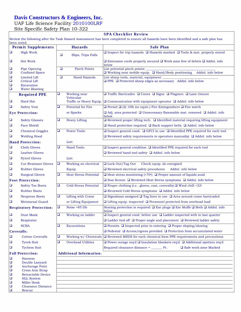
Davis Constructors & Engineers, Inc. UAF Life Science Facility 2010100LRF Site Specific Safety Plan 10-322
SPA Checklist Review
Review the following after the Task Hazard Assessment has been completed to ensure all hazards have been identified and a safe plan has been noted.
Permit Supplements Hazards Safe Plan
High Work Slips, Trips Falls
Inspect for trip hazards Hazards marked Tools & mat. properly stored
Hot Work Extension cords properly secured Work zone free of debris Addnl. info below
Pipe Opening Pinch Points List potential pinch points: ____________________________________________ Confined Space Working near mobile equip. Hand/Body positioning � Addnl. info below Limited Lift Hand Hazards List sharp tools, material, equipment: ___________________________________ Critical Lift PPE Protected sharp edges as necessary Addnl. info below Excavation Water Blasting
Required PPE Working near Vehicular
Traffic Barricades Cones Signs Flagmen Lane closure
Hard Hat Traffic or Heavy Equip. Communication with equipment operator Addnl. info below
Safety Vest Potential for Fire Permit (2) 10lb (or equiv.) Fire Extinguishers Fire watch
Eye Protection: or Sparks Adj. area protected Unnecessary flammable mat. removed Addnl. info below
Safety Glasses Heavy Lifting Reviewed proper lifting tech. Identified material requiring lifting equipment
Face Shield Hand protection required Back support belts Addnl. info below
Chemical Goggles Power Tools: Inspect general cond. GFCI in use Identified PPE required for each tool
Welding Hood Reviewed safety requirements in operators manual(s) Addnl. info below
Hand Protection: List:
Cloth Gloves Hand Tools: Inspect general condition Identified PPE required for each tool
Leather Gloves Reviewed hand tool safety Addnl. info below
Nytrel Gloves List:
Cut Resistant Gloves Working on electrical Lock Out/Tag Out � Check equip. de-energized
Rubber Gloves Equip. Reviewed electrical safety procedures � Addnl. info below
Surgical Gloves Heat Stress Potential Heat stress monitoring (>70o) Proper amount of liquids avail
Foot Protection: Sun Screen Reviewed Heat Stress symptoms Addnl. info below
Safety Toe Boots Cold Stress Potential Proper clothing (i.e.. gloves, coat, coveralls) Wind chill <32o
Rubber Boots Reviewed Cold Stress symptoms Addnl. info below
Neoprene Boots Lifting with Crane Signalman assigned Tag lines in use Area around crane barricaded
Metatarsal Guard or Lifting Equipment Lifting equip. inspected Personnel protected from overhead load
Respiratory Protection: Noise >85 Db Hearing protection is required: Ear plugs Ear Muffs Both Addnl. info below
Dust Mask Working on ladder Inspect general cond. before use Ladder inspected with in last quarter
Respirator Ladder tied off Proper angle and placement Reviewed ladder safety
SCBA Excavations Permits Inspected prior to entering Proper sloping/shoring
Coveralls: Pedestal Access/egress provided Protection from accumulated water
Cotton Coveralls Working w/ Chemicals Reviewed MSDS for each chemical form PPE requirements and precautions
Tyvek Suit Overhead Utilities Power outage req'd Insulation blankets req'd Additional spotters req'd
Tychem Suit Required clearance distance = _______ Ft. Safe work zone Marked
Fall Protection: Additional Information:
Harness Double Lanyard Anchorage Point Cross Arm Strap Retractable Device HLL System Miller Hook Clearance Distance Rescue

Davis Constructors & Engineers, Inc. UAF Life Science Facility 2010100LRF Site Specific Safety Plan 10-322 TAB 23: FORMS
Page 1 of 2
Safety Orientation
Policy for
Safety Orientation
Before a new employee or subcontractor may begin work they must participate in a Site Safety Orientation which explains the policies and mandatory safety requirements for working on a Davis construction project.
General Job Safety
Procedures
The following information has been conveyed to me: 1. Safety needs to be integrated into everything we do—think safe, don’t do
anything you feel is unsafe. 2. Attendance at daily or weekly safety meetings is required. Monday at
12:30. 3. How to obtain, use, and care for personal protective equipment.
• Appropriate clothing must be worn at all times on the jobsite. • Work boots, 4” sleeves, and long-legged pants (No tank tops or shorts). • Hardhats and safety glasses must be worn at all times. Exceptions
must be approved. • Reflective vest shall be worn when working outside.
4. How to perform initial job assignments in a safe manner through job hazard analysis (JHA).
5. Hazard Communication (HAZCOMM), jobsite postings, and environmental issues (SWPPP).
6. Actions to take in an emergency, including exit routes from the site, and safe gathering areas.
7. Employees are required to report to their supervisor immediately any and all unsafe conditions, injuries or illnesses, regardless of the degree of severity.
8. The location of first aid kits, fire extinguishers, and eyewash station. 9. Keep in mind that all employees are responsible for housekeeping. . 10. Inspect all electrical equipment and cords daily before use. All power
sources must be GFCI protected. 11. Daily inspection of all equipment prior to use. Equipment will be used
according to manufactures specifications. 12. Accident and injury reporting and employee rights and obligations
regarding workers’ compensation. 13. Operation, qualifications, and lockout/tag out of equipment. 14. Davis Constructors employees must undergo required drug testing prior
to the first day of employment. 15. Profane language will not be tolerated. 16. Cell phone policy.
Site Specific
Safety
1. Fall protection is required for any activity that exposes an employee to a
fall of six or more feet, if employees need to use fall protection they must

Davis Constructors & Engineers, Inc. UAF Life Science Facility 2010100LRF Site Specific Safety Plan 10-322 TAB 23: FORMS
Page 2 of 2
Procedures
attend specific training. 2. Emergency phone numbers are located on each safety station positioned at
the site entrance points. 3. No Smoking except in authorized areas. 4. SWPPP, report all spills and any water or liquids flowing off site. Spill kit. 5. Park only in authorized areas and observer posted speed limits on site as
these are strictly enforced. 6. Maintain the security of the jobsite by securing tools in locked gangboxes,
locking doors and gates. 7. Working around the public and traffic considerations. 8. Other site issues as needed.
Acts That Are Grounds For Immediate Dismissal
1. The use of alcohol or narcotics on the job or arrival on the job under the
influence of these substances. 2. No gambling, fighting, inciting riots, practical joking, horseplay, or
sexual/racial harassment. 3. Carrying firearms or dangerous weapons to the job site. 4. Theft of material, equipment, or supplies. 5. Unauthorized use of company vehicles, reckless driving, and operating
tagged out equipment. 6. Repeated minor, or a major violation of safety regulations
Employee or Subcontract-
or Signature
This informational form provides an overview and is not intended to be an all-inclusive list. Davis Constructors reserves the right to revise any policy at itssole discretion, at any time, without prior notice. All information in this orientation checklist was explained to me, and I agree to comply with Davis Constructors Safety policies. Print Name ________________________ Company _____________________ Sign Name ________________________ Date _____________________
Supervisor or
Briefer Signature
I explained all items in this orientation checklist to the employee. Print Name _________________________ Title ________________________
Sign Name _________________________ Date ________________________
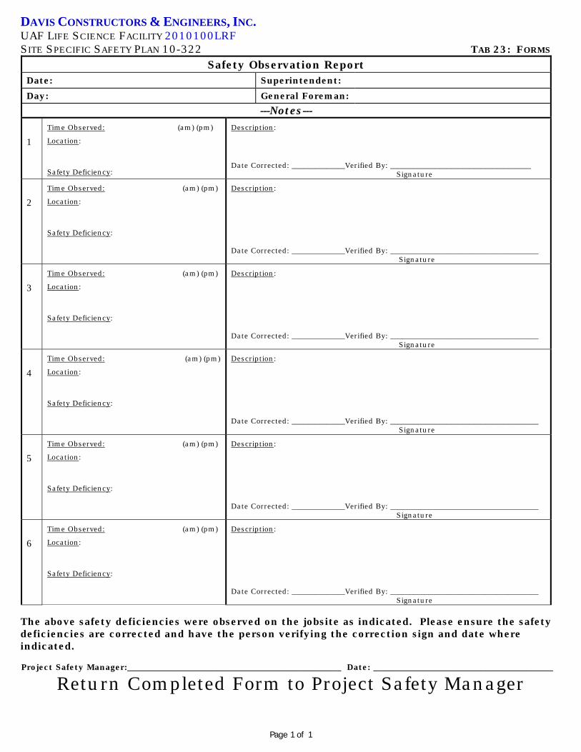
DAVIS CONSTRUCTORS & ENGINEERS, INC. UAF LIFE SCIENCE FACILITY 2010100LRF SITE SPECIFIC SAFETY PLAN 10-322 TAB 23: FORMS
Page 1 of 1
Safety Observation Report Date: Superintendent: Day: General Foreman:
---Notes--- 1
Time Observed: (am) (pm)
Location:
Safety Deficiency:
Description:
Date Corrected: ______________Verified By: _____________________________________ Signature
2
Time Observed: (am) (pm)
Location:
Safety Deficiency:
Description:
Date Corrected: ______________Verified By: _______________________________________ Signature
3
Time Observed: (am) (pm)
Location:
Safety Deficiency:
Description:
Date Corrected: ______________Verified By: _______________________________________ Signature
4
Time Observed: (am) (pm)
Location:
Safety Deficiency:
Description:
Date Corrected: ______________Verified By: _______________________________________ Signature
5
Time Observed: (am) (pm)
Location:
Safety Deficiency:
Description:
Date Corrected: ______________Verified By: _______________________________________ Signature
6
Time Observed: (am) (pm)
Location:
Safety Deficiency:
Description:
Date Corrected: ______________Verified By: _______________________________________ Signature
The above safety deficiencies were observed on the jobsite as indicated. Please ensure the safety deficiencies are corrected and have the person verifying the correction sign and date where indicated. Project Safety Manager:__________________________________________________ Date: __________________________________________
Return Completed Form to Project Safety Manager

Davis Constructors and Engineers, Inc.
Jobsite: UAF Life Science Date:#10-322 Time:
Meeting held by:
Name Employer Name Employer
Weekly Safety Meeting Sign in Sheet
Attendees:

Davis Constructors and Engineers, Inc.
Jobsite: UAF Life Science Date:#10-322 Time:
Meeting held by:
Action to be Taken
Weekly Safety Meeting
Items DiscussedItems Discussed