SITE SPECIFIC HEALTH AND SAFETY PLAN SUNCOR...
212
SITE SPECIFIC HEALTH AND SAFETY PLAN SUNCOR ENERGY INC. OUTLET 00271: 239 EDINBURGH ROAD NORTH, GUELPH, ONTARIO Prepared for: Suncor Energy Inc. Prepared by: Stantec Consulting Ltd. 49 Frederick Street Kitchener ON N2H 6M7 122120007 March 2010
Transcript of SITE SPECIFIC HEALTH AND SAFETY PLAN SUNCOR...
SITE SPECIFIC HEALTH AND SAFETY PLAN SUNCOR ENERGY INC. OUTLET 00271: 239 EDINBURGH ROAD NORTH, GUELPH, ONTARIO
Prepared for: Suncor Energy Inc. Prepared by: Stantec Consulting Ltd. 49 Frederick Street Kitchener ON N2H 6M7 122120007 March 2010

SITE SPECIFIC HEALTH AND SAFETY PLAN SUNCOR ENERGY INC. OUTLET 00271: 239 EDINBURGH ROAD NORTH, GUELPH, ONTARIO
EMERGENCY INFORMATION SHEET
Project Information
Stantec Project Number: 12212007.223 (ONW35457) Project Location: Portions of London Road and Edinburgh Road adjacent to
former Suncor Energy Inc. Retail Outlet No. 00271 located at 239 Edinburgh Road North (at London Road), in Guelph, Ontario
Client Information
Client Name and Address: Suncor Energy Inc. 3275 Rebecca Street Oakville, Ontario L6L 6N5
Suncor Energy Inc. Project Manager: (Primary Contact)
Ken Tedder, P.Eng., Senior Environmental Advisor Office: (905) 469-3754 Cellular: (416) 606-1647
Suncor Energy Inc. Alternative Contact:
Alain Gravel, P.Eng., Environmental Advisor Office: (905) 469-3967 Cellular: (416) 435-7775
Consultant Information
Consultant Name and Address: Stantec Consulting Ltd. 3430 South Service Road, Suite 203 Burlington, Ontario L7N 3T9 Main Tel: (905) 631-8684 Fax: (905) 631-8960
Stantec Project Manager: (Primary Contact)
Karen Wright, B.Sc. Env. Office: (905) 631-3909 Cellular: (416) 434-0145 Home: (289) 878-8763
Stantec Alternative Contact: Steve Dutaud, P.Geo. (Client Manager) Office: (905) 631-3905 Cellular: (416) 347-6652 Home: (905) 426-8334
hls v:\01221\active\122120007_hasp\hasp contact table_100305.doc S.1
SITE SPECIFIC HEALTH AND SAFETY PLAN SUNCOR ENERGY INC. OUTLET 00271: 239 EDINBURGH ROAD NORTH, GUELPH, ONTARIO EMERGENCY INFORMATION SHEET March 5, 2010
hls v:\01221\active\122120007_hasp\hasp contact table_100305.doc S.2
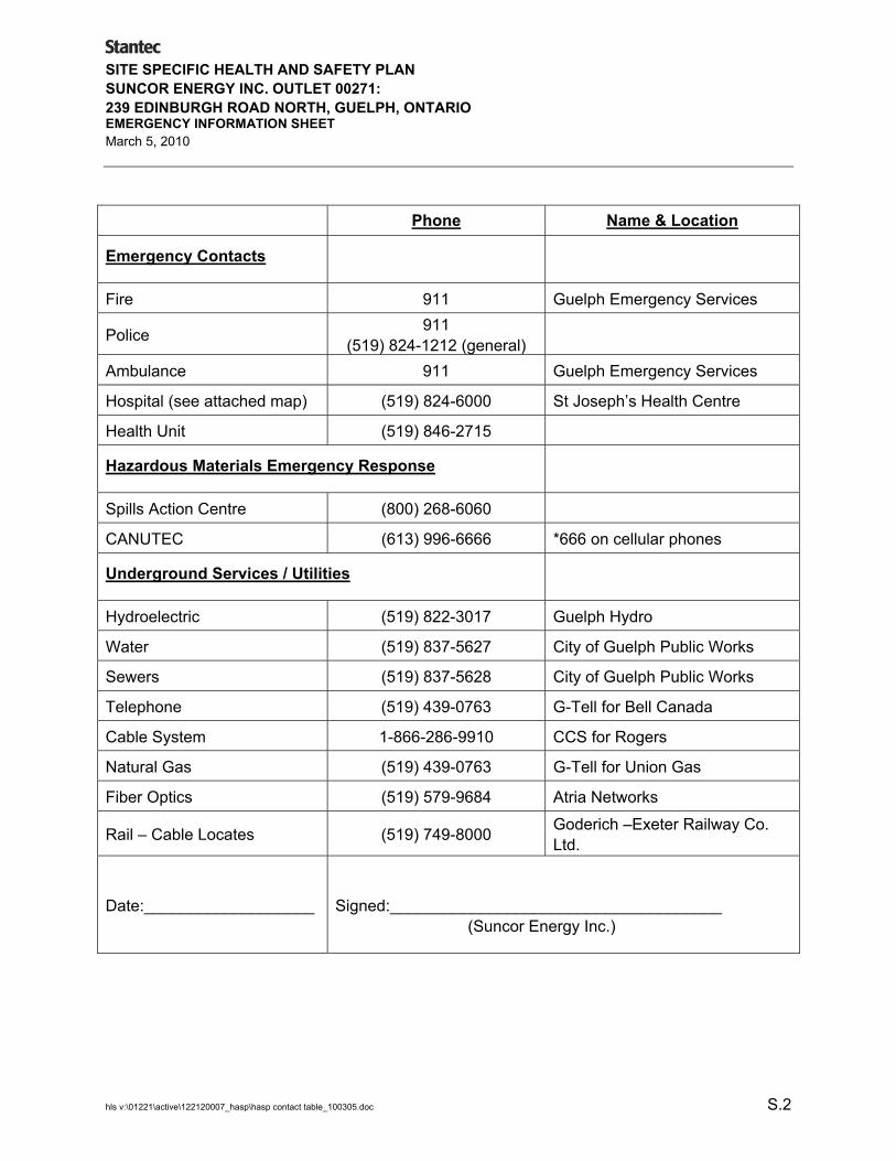
Phone Name & Location
Emergency Contacts
Fire 911 Guelph Emergency Services
Police 911 (519) 824-1212 (general)
Ambulance 911 Guelph Emergency Services
Hospital (see attached map) (519) 824-6000 St Joseph’s Health Centre
Health Unit (519) 846-2715
Hazardous Materials Emergency Response
Spills Action Centre (800) 268-6060
CANUTEC (613) 996-6666 *666 on cellular phones
Underground Services / Utilities
Hydroelectric (519) 822-3017 Guelph Hydro
Water (519) 837-5627 City of Guelph Public Works
Sewers (519) 837-5628 City of Guelph Public Works
Telephone (519) 439-0763 G-Tell for Bell Canada
Cable System 1-866-286-9910 CCS for Rogers
Natural Gas (519) 439-0763 G-Tell for Union Gas
Fiber Optics (519) 579-9684 Atria Networks
Rail – Cable Locates (519) 749-8000 Goderich –Exeter Railway Co. Ltd.
Date:___________________
Signed:_____________________________________ (Suncor Energy Inc.)
SITE SPECIFIC HEALTH AND SAFETY PLAN SUNCOR ENERGY INC. OUTLET 00271: 239 EDINBURGH ROAD NORTH, GUELPH, ONTARIO EMERGENCY INFORMATION SHEET March 5, 2010
hls v:\01221\active\122120007_hasp\hasp contact table_100305.doc S.3
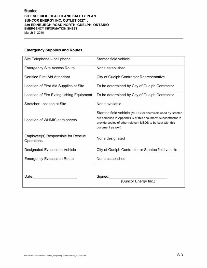
Emergency Supplies and Routes
Site Telephone – cell phone Stantec field vehicle
Emergency Site Access Route None established
Certified First Aid Attendant City of Guelph Contractor Representative
Location of First Aid Supplies at Site To be determined by City of Guelph Contractor
Location of Fire Extinguishing Equipment To be determined by City of Guelph Contractor
Stretcher Location at Site None available
Location of WHMIS data sheets
Stantec field vehicle (MSDS for chemicals used by Stantec are compiled in Appendix C of this document; Subcontractor to provide copies of other relevant MSDS to be kept with this document as well)
Employee(s) Responsible for Rescue Operations None designated
Designated Evacuation Vehicle City of Guelph Contractor or Stantec field vehicle
Emergency Evacuation Route None established
Date:_____________________
Signed:____________________________ (Suncor Energy Inc.)

Table 1 Summary of General Health Hazards and First Aid Procedures
First Aid Measures Specific Compound Use / Source Description Exposure Limits Monitor
Indicators Incompatibility Eyes Ingested Inhaled
1) Potential On Site Compounds
Regular Unleaded Gasoline
Source: Adjacent property
Bronze colour, clear and bright liquid with hydrocarbon odour
REL: 300 ppm PEL: 300 ppm
LEL: 1.4 % UEL: 7.6 % IP: not available
Avoid heat, sparks, open flame and contact with strong oxidizing agents. Prevent vapour accumulation.
Flush with water for 15 minutes while holding eyelids open. Get medical attention.
Seek medical attention immediately
Remove affected person to fresh air. If breathing stops, perform artificial respiration. Get medical attention.
Diesel Fuel Source: Adjacent property
Yellow liquid with strong hydrocarbon odour
Not Established Not available Avoid heat, flame and contact with strong oxidizing agents.
Flush with water, if irritation occurs get medical attention.
DO NOT INDUCE VOMITING, get medical attention
Remove affected person to fresh air and provide oxygen if breathing is difficult. Get medical attention.
Benzo (a) Pyrene Suspected carcinogen
Source: Adjacent property
Slightly brown As benzene solubles: REL: not available PEL: 0.2 mg/m3
(listed under coal tar)
Not available Strong oxidizing agents.
Flush with plenty of water for 15 minutes, occasionally lifting lids. Seek medical attention.
DO NOT INDUCE VOMITING, if casualty is alert and not convulsing rinse mouth and give 2 -4 cups of water. Seek Immediate medical attention
Remove affected person to fresh air and provide oxygen if breathing is difficult. Get medical attention.
REL – NIOSH recommended exposure limit (time weighted average concentrations for up to a 10-hour work day) PEL – OSHA permissible exposure limit (time weighted average concentrations for any 8-hour work shift) TLV – threshold limit value (time weighted average concentrations for up to a 10-hour work day) IP – Ionization Potential ; LEL – Lower Explosive Limit; UEL – Upper Explosive Limit
05 March 2010 S.4
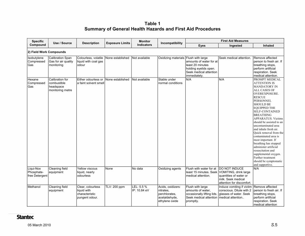
Table 1 Summary of General Health Hazards and First Aid Procedures
First Aid Measures Specific Compound Use / Source Description Exposure Limits Monitor
Indicators Incompatibility Eyes Ingested Inhaled
2) Field Work Compounds
Isobutylene Compressed Gas
Calibration Span Gas for air quality monitoring
Colourless, volatile liquid with coal gas odour
None established Not available Oxidizing materials Flush with large amounts of water for at least 20 minutes holding eyelids open. Seek medical attention immediately.
Seek medical attention. Remove affected person to fresh air. If breathing stops, perform artificial respiration. Seek medical attention. PROMPT MEDICAL ATTENTION IS MANDATORY IN ALL CASES OF OVEREXPOSURE. RESCUE PERSONNEL SHOULD BE EQUIPPED THE SELF-CONTAINED BREATHING APPARATUS. Victims should be assisted to an uncontaminated area and inhale fresh air. Quick removal from the contaminated area is most important. If breathing has stopped administer artificial resuscitation and supplemental oxygen. Further treatment should be symptomatic and supportive.
Hexane Compressed Gas
Calibration for combustible headspace monitoring metre
Either odourless or a faint solvent smell
None established Not available Stable under normal conditions
N/A N/A
Liqui-Nox Phosphate-free Detergent
Cleaning field equipment
Yellow viscous liquid, nearly odourless
None No data Oxidizing agents Flush with water for at least 15 minutes. Seek medical attention.
DO NOT INDUCE VOMITING, drink large quantities of water or milk. Seek medical attention for discomfort.
N/A
Methanol Cleaning field equipment
Clear, colourless liquid with characteristic pungent odour.
TLV: 200 ppm LEL: 5.5 % IP: 10.84 eV
Acids, oxidizers: nitrates, perchlorates, acetaldehyde, ethylene oxide
Flush with large amounts of water, occasionally lifting lids. Seek medical attention promptly.
Induce vomiting if victim conscious. Dilute with 2 glasses of water. Seek medical attention..
Remove affected person to fresh air. If breathing stops, perform artificial respiration. Seek medical attention
05 March 2010 S.5

Directions to 115 Delhi St, Guelph, ON 4.0 km – about 6 mins Directions to Guelph General Hospital
Loading...
©2010 Google - Map data ©2010 Google, Tele Atlas -
Page 1 of 2239 Edinburgh Rd N, Guelph, ON to 115 Delhi St, Guelph, ON - Google Maps
3/5/2010http://maps.google.ca/maps?f=d&source=s_d&saddr=239+Edinburgh+Rd+N,+Guelph,+We...

These directions are for planning purposes only. You may find that construction projects, traffic, weather, or other events may cause conditions to differ from the map results, and you should plan your route accordingly. You must obey all signs or notices regarding your route. Map data ©2010 Google, Tele Atlas
Directions weren't right? Please find your route on maps.google.ca and click "Report a problem" at the bottom left.
239 Edinburgh Rd N, Guelph, ON
1. Head northwest on Edinburgh Rd N toward Willow Rd About 2 mins
go 1.3 km total 1.3 km
2. Turn right at Speedvale Ave W About 3 mins
go 1.7 km total 3.0 km
3. Turn right at Delhi St Destination will be on the left About 2 mins
go 1.0 km total 4.0 km
115 Delhi St, Guelph, ON
Page 2 of 2239 Edinburgh Rd N, Guelph, ON to 115 Delhi St, Guelph, ON - Google Maps
3/5/2010http://maps.google.ca/maps?f=d&source=s_d&saddr=239+Edinburgh+Rd+N,+Guelph,+We...

SITE SPECIFIC HEALTH AND SAFETY PLAN SUNCOR ENERGY INC. OUTLET 00271: 239 EDINBURGH ROAD NORTH, GUELPH, ONTARIO
Table of Contents Page
STANTEC EMERGENCY INFORMATION SHEET S.1
1.0 INTRODUCTION ................................................................................................................1.1 1.1 REQUIREMENTS FOR STANTEC EMPLOYEES AND STANTEC
SUBCONTRACTORS.........................................................................................................1.2 1.1.1 Stantec Employees ..............................................................................................1.2 1.1.2 City of Guelph’s Contractors ................................................................................1.2 1.1.3 Stantec’s Subcontractors .....................................................................................1.3
1.2 HEALTH & SAFETY PLAN - LIMITATIONS OF USE.........................................................1.3
2.0 SITE BACKGROUND AND OPERATIONS .......................................................................2.1
3.0 HAZARD IDENTIFICATION ...............................................................................................3.1 3.1 PRIMARY ENVIRONMENTAL HAZARDS .........................................................................3.1 3.2 PERSONAL CONDUCT AND HYGIENE............................................................................3.1 3.3 POTENTIAL SITE HAZARDS.............................................................................................3.3
3.3.1 Physical................................................................................................................3.3 3.3.2 Chemical ..............................................................................................................3.3 3.3.3 Electrical and Other Utilities.................................................................................3.4 3.3.4 Fire and Explosion ...............................................................................................3.5 3.3.5 Oxygen Deficiency ...............................................................................................3.6 3.3.6 Ionizing Radiation ................................................................................................3.6 3.3.7 Biological..............................................................................................................3.6 3.3.8 Stress and Fatigue...............................................................................................3.7 3.3.9 Noise....................................................................................................................3.7 3.3.10 Personal Security.................................................................................................3.7 3.3.11 Other Site Activities..............................................................................................3.8 3.3.12 Adverse Weather Conditions ...............................................................................3.8
4.0 PERSONAL PROTECTIVE EQUIPMENT..........................................................................4.1 4.1 MINIMUM LEVEL D PPE REQUIREMENTS FOR ALL SITE PERSONNEL......................4.1 4.2 SELECTION, MAINTENANCE AND CONTINUAL ASSESSMENT ...................................4.1 4.3 UPGRADING TO LEVEL C PPE ........................................................................................4.2
5.0 SITE MANAGEMENT.........................................................................................................5.1 5.1 SITE CONTROL MEASURES ............................................................................................5.1 5.2 ROLES AND RESPONSIBILITIES .....................................................................................5.2 5.3 CONTINUOUS HAZARD MONITORING............................................................................5.2
hls v:\01221\active\122120007_hasp\hasp_100305.doc i

SITE SPECIFIC HEALTH AND SAFETY PLAN SUNCOR ENERGY INC. OUTLET 00271: 239 EDINBURGH ROAD NORTH, GUELPH, ONTARIO
Table of Contents 6.0 ACTION LEVELS ...............................................................................................................6.1
7.0 CONFINED SPACE ENTRY...............................................................................................7.1
8.0 DECONTAMINATION PROCEDURES ..............................................................................8.1
9.0 MEDICAL SURVEILLANCE PROGRAM...........................................................................9.1
10.0 EMERGENCY PREPAREDNESS AND RESPONSE ......................................................10.1 10.1 FIRST AID.........................................................................................................................10.1 10.2 FIRE PROTECTION .........................................................................................................10.1 10.3 SPILL OR LEAK OF HAZARDOUS CHEMICALS ............................................................10.2
11.0 REFERENCES .................................................................................................................11.1
hls v:\01221\active\122120007_hasp\hasp_100305.doc ii

SITE SPECIFIC HEALTH AND SAFETY PLAN SUNCOR ENERGY INC. OUTLET 00271: 239 EDINBURGH ROAD NORTH, GUELPH, ONTARIO
Table of Contents
List of Appendices
Appendix A Stantec Consulting Ltd. – Safe Work Practices Appendix B WHMIS Material Safety Data Sheets Appendix C Health and Safety Statement of Compliance Forms
List of Figures
Figure S1 Directions to Hospital – St. Joseph’s Health Centre S.6
Figure 1 Site Location Map Figure 2 Site Plan
List of Tables
Table 1 Summary of General Health Hazards and First Aid Procedures S.4
hls v:\01221\active\122120007_hasp\hasp_100305.doc iii

SITE SPECIFIC HEALTH AND SAFETY PLAN SUNCOR ENERGY INC. OUTLET 00271: 239 EDINBURGH ROAD NORTH, GUELPH, ONTARIO
1.0 Introduction
This Site-Specific Health and Safety Plan (HASP) has been prepared to provide Stantec Consulting Ltd. (Stantec) staff, subcontractors retained by Stantec and City of Guelph contractors with the necessary information to ensure that all field work associated with the handling of petroleum hydrocarbon impacted soil and groundwater is completed in a safe manner in accordance with standard safety practices and procedures. The plan also provides information for contingencies that may arise during road reconstruction and utility replacement work related to both health risks associated with environmental conditions and accidental injury during site work. This plan shall be available at the site during all field activities.
As requested by Suncor Energy Inc. (Suncor) this HASP was prepared by Stantec for activities to be completed in conjunction with the City of Guelph’s roadway reconstruction and utility upgrades in the vicinity of the former Petro-Canada branded retail outlet located at 239 Edinburgh Road North that could potentially encounter petroleum impacted soil and/or groundwater. The specific activities to be conducted by Stantec at the intersection of Edinburgh Road North and London Road West located in Guelph, Ontario (the Site) as part of the road reconstruction and utility replacement work include:
• Decommissioning of previously installed monitoring wells on Edinburgh Road North and London Road West;
• Soil and groundwater sample collection and handling during the road reconstruction and utility replacement work;
• Provision of guidance to the City of Guelph’s contractor for the segregation of encountered potentially petroleum impacted soils; and,
• Retention of qualified firm to provide specific air testing and confined space entry supervision should encountered field conditions warrant entry by the City of Guelph’s contractor into petroleum hydrocarbon impacted excavations.
The contents of this HASP are a minimum expectation and are to be exceeded where site specific practice, government regulations or common sense dictates. A fundamental aspect of site safety is awareness and common sense. Stantec employees, Stantec’s Subcontractors and workers who could potentially encounter petroleum impacted soil and/or groundwater shall abide by the HASP when on the Site when engaging in the above listed activities. This HASP is intended to form a portion of the overall health and safety plan prepared by the City of Guelph’s contractor for the roadway reconstruction and utility upgrade program. Regular communication with appropriate City of Guelph personnel and/or their contractors will be maintained while on the Site.
hls v:\01221\active\122120007_hasp\hasp_100305.doc 1.1

SITE SPECIFIC HEALTH AND SAFETY PLAN SUNCOR ENERGY INC. OUTLET 00271: 239 EDINBURGH ROAD NORTH, GUELPH, ONTARIO Introduction March 5, 2010
hls v:\01221\active\122120007_hasp\hasp_100305.doc 1.2
1.1 REQUIREMENTS FOR STANTEC EMPLOYEES AND STANTEC SUBCONTRACTORS
1.1.1 Stantec Employees
Stantec employees shall review and be fully aware of the following documented policies and procedures before entering the Site for the first time:
• Stantec Site Specific Health and Safety Plan (contained herein).
• Stantec Safe Work Procedures (contained in Appendix A).
After reviewing these documents, Stantec employees shall complete the following form contained in Appendix D and ensure that the Stantec Site Safety Coordinator receives the original signed form:
• Stantec Employee Statement of Compliance – Review of HASP.
Employees shall abide by all City of Guelph Health and Safety policies and attend all required site safety meetings as conducted by either the City of Guelph staff, or their contractor.
Stantec employees shall then review Appendix C to ensure that WHMIS Material Safety Data Sheets (MSDS) are readily available on-site for any chemicals known to be present at the Site. New or revised MSDS shall be added to Appendix C and outdated MSDS removed, as appropriate.
In addition, all Stantec employees will have completed Petroleum Oriented Safety Training (POST) training for the year the work is being completed in, and are able to produce proof of training upon request (i.e., have a certificate of training, POST helmet sticker or POST wallet care with them on-site). After completing the tasks described above, Stantec employees may now enter the Site.
1.1.2 City of Guelph’s Contractors
It is the understanding of Stantec that the City of Guelph’s Contractors are responsible for the health and safety of its employees and subcontractors and for the road reconstruction and utility replacement project as a whole.
The City of Guelph’s contractors shall prepare a site-specific HASP. A copy of contractor’s HASP shall be provided to Stantec for review prior to Stantec employees attending the site. In addition a copy of Stantec’s HASP will be provided to the City of Guelph and their designated contractor. The City of Guelph’s contractors’ HASP could include, but not be limited to, requirements for qualifications and experience, training, medical fitness, documented proof of

SITE SPECIFIC HEALTH AND SAFETY PLAN SUNCOR ENERGY INC. OUTLET 00271: 239 EDINBURGH ROAD NORTH, GUELPH, ONTARIO Introduction March 5, 2010
hls v:\01221\active\122120007_hasp\hasp_100305.doc 1.3
training and fitness, personal protective equipment, and adherence to safety regulations, guidelines and other industry-accepted standards.
1.1.3 Stantec’s Subcontractors
Subcontractors that are hired by Stantec to complete tasks related to the scope of this HASP are responsible for the health and safety of their employees.
A copy of Stantec’s HASP will be provided to each Subcontractor. Subcontractors’ HASP could include, but not be limited to, requirements for qualifications and experience, training, medical fitness, documented proof of training and fitness, personal protective equipment, and adherence to safety regulations, guidelines and other industry-accepted standards.
After reviewing these documents, Subcontractors shall complete the form contained in Appendix D and ensure that the Stantec Site Safety Coordinator receives the original signed form:
• Subcontractor Statement of Compliance – Review of HASP
Subcontractors shall attend applicable site safety meetings conducted by the City of Guelph staff or their contractor, and sign the form contained in Appendix D to document attendance at each meeting.
Subcontractors shall ensure that WHMIS Material Safety Data Sheets (MSDS) are readily available on-site for any chemicals known to be present at the Site pertaining to their scope of work. New or revised MSDS shall be added to Subcontractor’s HASP, and outdated MSDS removed, as appropriate. Subcontractor shall provide Stantec with copies of all MSDS for any chemicals brought by Subcontractor to the Site.
In addition, all Stantec Subcontractors will have completed Petroleum Oriented Safety Training (POST) training for the year the work is being completed in, and will able to produce proof of training upon request (i.e., have a certificate of training with them on-site).
After completing the tasks described above, Subcontractors may now enter the Site.
1.2 HEALTH & SAFETY PLAN - LIMITATIONS OF USE
This HASP has been developed specifically for the Site activities anticipated to be conducted by Stantec employees or Stantec subcontractors at the Site, as listed below. Adequate provision may not be provided by the procedures outlined in this HASP for unanticipated activities which fall outside the range of site activities listed below. The site worker, whether he/she be a Stantec employee or Subcontractor, shall inform the Stantec Site Safety Coordinator or the Stantec Project Manager of any planned activities not believed to be covered by this HASP

SITE SPECIFIC HEALTH AND SAFETY PLAN SUNCOR ENERGY INC. OUTLET 00271: 239 EDINBURGH ROAD NORTH, GUELPH, ONTARIO Introduction March 5, 2010
hls v:\01221\active\122120007_hasp\hasp_100305.doc 1.4
before undertaking said activity. Upon being brought to Stantec’s attention, the Stantec Site Safety Coordinator will review the matter, update the HASP or ensure the Subcontractor’s HASP is updated as appropriate, and ensure any revisions are communicated to the site workers.
Activities anticipated to be conducted by Stantec at the Site are:
• Site reconnaissance and observation;
• Decommissioning of existing groundwater monitoring wells (MW201, MW202, MW203, MW204, MW205 and MW206) as indicated on Figure 1;
• Collection of soil and groundwater samples as needed throughout the roadway reconstruction activities; and,
• Retention of qualified firm to provide specific air testing and confined space entry supervision should encountered field conditions warrant entry by the City of Guelph’s contractor into petroleum hydrocarbon impacted excavations

SITE SPECIFIC HEALTH AND SAFETY PLAN SUNCOR ENERGY INC. OUTLET 00271: 239 EDINBURGH ROAD NORTH, GUELPH, ONTARIO
2.0 Site Background and Operations
As indicated in Section 1, the Site is located at the intersection of Edinburgh Road North and London Road West in Guelph, Ontario.
The primary environmental concern at the Site is possible subsurface petroleum hydrocarbons and its indicator compounds as summarized below:
• The most common petroleum hydrocarbon compounds on site consist of a variety of blended streams of crude distillates which can be identified by a series of indicator compounds. The most common of these indicators are benzene, toluene, ethylbenzene and xylenes (BTEX) and Petroleum Hydrocarbon Fractions (F1 to F4). These are the primary potential on-Site compounds derived from the substances being investigated.
hls v:\01221\active\122120007_hasp\hasp_100305.doc 2.1

SITE SPECIFIC HEALTH AND SAFETY PLAN SUNCOR ENERGY INC. OUTLET 00271: 239 EDINBURGH ROAD NORTH, GUELPH, ONTARIO
3.0 Hazard Identification
This section presents an assessment of the actual and potential hazards that have been identified at the Site, and measures that shall be undertaken to minimize the potential for impacts to health and safety (Section 3.1). In addition, Stantec’s specific policies and procedures are presented for personal conduct and hygiene (Section 3.2), and general safety to minimize/prevent other potential safety hazards (Section 3.3). While the latter two sections describe potential hazards that are common to most, if not all work sites, the importance of employee awareness and the exercise of good common sense, by adhering to the policies and procedures presented herein, can not be over-emphasized.
If the City of Guelph’s contractor is required to enter into confined utility trench excavations that are impacted with petroleum hydrocarbons, Stantec will retain a qualified firm to evaluate and subsequently provide specific air testing and confined space entry supervision as necessary.
3.1 PRIMARY ENVIRONMENTAL HAZARDS
Petroleum Hydrocarbons are the primary concern at the Site. For this reason, MSDS for diesel fuel and gasoline have been included in Appendix C.
In addition to the chemicals potentially present at the Site, chemicals typically used by Stantec employees to collect samples, decontaminate field equipment and calibrate field instruments include the following:
• Liqui-Nox™ (phosphate-free detergent) and methanol for cleaning sampling equipment and water-level indicator meters; and
• Hexane for calibration checks performed on gas detection meters.
MSDS for the chemicals typically used by Stantec employees as noted above have been included in Appendix C.
Table 1 presents a summary of general chemical properties and associated screening targets for the chemicals listed above and a few other chemicals which may potentially be used by Stantec employees at the Site. The health hazards and first aid procedures for the chemicals field personnel may potentially contact on-site during routine field investigations are also presented in Table 1.
3.2 PERSONAL CONDUCT AND HYGIENE
Poor personal conduct and hygiene is a common cause for accidents and direct exposure to chemicals. The following list represents the minimum requirements for personal conduct and hygiene at the Site:
hls v:\01221\active\122120007_hasp\hasp_100305.doc 3.1

SITE SPECIFIC HEALTH AND SAFETY PLAN SUNCOR ENERGY INC. OUTLET 00271: 239 EDINBURGH ROAD NORTH, GUELPH, ONTARIO Hazard Identification March 5, 2010
hls v:\01221\active\122120007_hasp\hasp_100305.doc 3.2
• No worker shall enter the Site while under the influence of intoxicants, narcotics, controlled substances or medication that may in any way adversely affect alertness, concentration, reaction response time or safety.
• No worker shall enter the Site or continue working when illness, fatigue, hunger, mental state or otherwise may in any way adversely affect alertness, concentration, reaction response time or safety.
• Workers shall engage in activities for which they are qualified and with the utmost regard for the safety and wellbeing of themselves, other workers and the community.
• Smoking, eating, drinking and chewing (gum or tobacco) are prohibited at the Site, except in designated areas to be determined by the City of Guelph contractor’s health and safety representative. Designated areas will be established where the potential risks of fire, explosion and ingestion of contaminants are negligible.
• Direct contact with liquid and solid materials (e.g., chemicals, wastes or contaminated soil/water) shall be minimized. Workers shall minimize walking, kneeling, sitting or otherwise occupying or storing equipment in areas that contain or may contain contaminants.
• Workers shall wash and dry their hands before taking a break to eat, drink, smoke or use toilet facilities if the worker may have been in contact with site contaminants.
• Workers that are non-essential to the performance of site activities shall not enter and/or linger in or around areas where these tasks are being performed.
• Contact lenses shall not be worn in potentially contaminated atmospheres (e.g., chemical vapours, dust or other airborne particulates).
• Workers with abrasions, cuts or punctured eardrums have enhanced pathways for chemical exposure and shall identify themselves to the City of Guelph contractor’s health and safety representative for assessment prior to site entry.
• Where the potential for respirator use has been identified at a site, workers with facial hair (e.g., unshaved, beards, mustaches, etc.) shall not be permitted to enter the site if the presence of the facial hair may interfere with proper respirator fit and use.
• Every worker is responsible for ensuring the site is kept free of discarded or blowing trash. All wastes shall be placed into appropriate containers.

SITE SPECIFIC HEALTH AND SAFETY PLAN SUNCOR ENERGY INC. OUTLET 00271: 239 EDINBURGH ROAD NORTH, GUELPH, ONTARIO Hazard Identification March 5, 2010
hls v:\01221\active\122120007_hasp\hasp_100305.doc 3.3
3.3 POTENTIAL SITE HAZARDS
The following potential hazards are common to most sites. Stantec’s policies and procedures to minimize/prevent these potential hazards have been developed from standard safety policies and procedures, and by applying common sense.
3.3.1 Physical
Physical hazards include the following:
• Slip, trip and fall (e.g., wet surfaces, steep/uneven terrain, holes)
• Dropped items (e.g., from back of equipment or top of drill rig)
• Cave-in or collapse (e.g., floors, walls, excavation sides)
• Sharp objects (e.g., nails, metal shards, broken glass)
• Moving parts (e.g., excavator bucket, drill rig augers and cables)
• Poor visibility (e.g., poor daylight, smoke, dust, fog)
• Traffic (e.g., construction, vehicular or rail)
• Working around mobile heavy machinery (e.g. drill rigs, vacuum trucks, excavators, graders)
Good housekeeping, appropriate personal protective equipment (PPE), and alert workers exercising good common sense will minimize or prevent potential injury from physical hazards. Loose equipment and spilled liquids will be cleaned up. The appropriate PPE shall be worn at all times and shall be replaced when it becomes worn-out or damaged. The number of ongoing activities, number of workers and pace of activities shall be kept manageable. Reckless or careless workers will be removed from the site.
Physical hazards related to construction traffic present a significant health and safety concern at the Site.
3.3.2 Chemical
The chemicals of potential concern at the Site have been described in Section 3.1.
Chemical exposures are generally divided into two categories: acute and chronic. Symptoms resulting from acute exposures usually occur during or shortly after exposure to a high concentration of a chemical of concern. Chronic exposure generally refers to exposure to low concentrations to chemicals of concern over a prolonged period. Some chemicals may cause

SITE SPECIFIC HEALTH AND SAFETY PLAN SUNCOR ENERGY INC. OUTLET 00271: 239 EDINBURGH ROAD NORTH, GUELPH, ONTARIO Hazard Identification March 5, 2010
hls v:\01221\active\122120007_hasp\hasp_100305.doc 3.4
obvious symptoms such as burning, coughing, nausea, tearing or rashes. Other chemicals may not have such warning signs (this is a particular concern for chronic exposures). In addition, some chemicals of concern may be colourless and / or odourless, or may cause olfactory fatigue; therefore, a field person’s senses may not be relied upon to warn of potential exposure. MSDS give a description of the chemical of concern, and information regarding exposure limits, monitoring indicators and first aid measures. As mentioned previously, MSDS for the anticipated environmental remediation activities are provided in Appendix C.
Evaluating the hazards of these chemicals involves consideration of potential exposure pathways to personnel during site activities. Potential exposure pathways are as follows:
• Eye and skin contact with vapours, liquids and soils;
• Inhalation of vapours and airborne particulates; and,
• Accidental ingestion of soils and /or groundwater.
Dermal absorption of chemicals through direct eye or skin contact with airborne particulates, soils or groundwater may also be an exposure pathway. Protection against dermal contact and absorption of chemicals will be accomplished through the use of appropriate PPE as described in Section 4.0.
Inhalation of vapours and airborne particulates represent the greatest potential for exposure to chemical hazards by field personnel. Accidental ingestion of chemical substances also represents an exposure hazard. The potential for inhalation of vapours will be monitored as described in Section 5.3. Precautions will be taken to keep dust levels to a minimum when working in areas of potential petroleum hydrocarbon impacts. If noticeable dust is generated during site activities, the activities will be stopped until appropriate engineering controls are implemented. Personal habits such as chewing gum or tobacco, drinking, eating, and smoking on-site may provide a route of entry for chemicals. Field personnel shall conduct themselves as outlined in Section 3.2 while on-site.
3.3.3 Electrical and Other Utilities
All below grade and overhead utilities will be located and marked before initiating any subsurface drilling or excavations. Stantec will arrange with the appropriate utility companies, site contact and/or independent utility locating subcontractor to have all utilities located prior to starting Stantec’s well decommissioning activities. Where the location of buried utilities remains uncertain, Subcontractor will hand excavate or otherwise cautiously advance through the upper 2 m at each intrusive testing location or a Hydrovac for the purposes of daylighting will be employed.

SITE SPECIFIC HEALTH AND SAFETY PLAN SUNCOR ENERGY INC. OUTLET 00271: 239 EDINBURGH ROAD NORTH, GUELPH, ONTARIO Hazard Identification March 5, 2010
hls v:\01221\active\122120007_hasp\hasp_100305.doc 3.5
Under the Ontario Occupational Health and Safety Regulations (RSO 1990), the minimum safe distance for work within overhead power lines is summarized in the table below.
Nominal Phase to Phase Voltage Rating Minimum Distance
750 Volts or more, but no more than 150,000 Volts 3 meters
More than 150,000 Volts, but no more than 250,000 Volts
4.5 meters
More than 250,000 Volts 6 meters
Before work begins, Stantec will contact the electrical utility and request written confirmation of the line voltage and safe distance of approach. If written confirmation is unavailable from the electrical utility, Stantec will maintain a minimum safe distance of approach of 6 m, unless the Stantec Project Manager indicates that it has been determined to be safe to approach up to 3 m. A signal person will be used if the operator of equipment does not have a clear view of the path to be traveled by equipment and its load.
All Stantec employees and Subcontractors shall follow the electrical safety measures provided in Stantec Health Safety and Environment Program document HSE-650 (refer to Appendix A).
Additionally, equipment (e.g., generator, power tools, welding equipment) will not be operated in wet conditions (e.g., puddles, swampy areas, rainfall, etc.), during electrical storms, or any other conditions posing electrical hazards of shock or electrocution.
3.3.4 Fire and Explosion
Fire and explosion hazards may be associated with flammable vapours from products stored in tanks (above or below ground) as well as from spilled or leaked product or the sudden release of materials under pressure (e.g., propane cylinders). For combustion of flammable substances to occur, fuel, oxygen and an ignition source are necessary. Recognition, evaluation and control of the elements is necessary for the safety of field personnel.
The presence of potential sources of ignition (heat, flame or spark-producing action) will be minimized as follows:
• Smoking is prohibited on-site, except in designated areas;
• All open flame and spark-producing equipment will be shut-down during on-site activities;

SITE SPECIFIC HEALTH AND SAFETY PLAN SUNCOR ENERGY INC. OUTLET 00271: 239 EDINBURGH ROAD NORTH, GUELPH, ONTARIO Hazard Identification March 5, 2010
hls v:\01221\active\122120007_hasp\hasp_100305.doc 3.6
• Static electricity will be controlled by minimizing agitation or static-producing movement by grounding equipment and vehicles; and,
• Monitoring for explosive atmospheres and flammable vapours will be conducted as described in Section 5.3, as appropriate.
3.3.5 Oxygen Deficiency
The oxygen content of air is approximately 21%. Oxygen-deficient atmospheres are considered to have an oxygen content of 19.5% or lower. Oxygen-deficient atmospheres are hazardous, not only because of the risk of asphyxiation, but because the low oxygen levels may be the direct result of the build-up of explosive gases as well. Oxygen-enriched atmospheres pose an increased risk of fire and explosion, and are considered to have an oxygen content of 25% or greater.
Oxygen deficiency or enrichment could be encountered hazard during trenching, excavation or pipe installation activities.
3.3.6 Ionizing Radiation
Radioactive materials emit one or more of three types of radiation (alpha, beta and gamma) which may be harmful to workers depending on the type and amount of radiation. Radiation levels of 2 millirem per hour (2 mrem/hr) are considered Immediately Dangerous to Life and Health (IDLH) and all site activities should cease until an appropriate radiation assessment has been completed and site safety procedures are in-place. If there is the potential for radiation levels at a site to be above natural background levels, site-specific safety procedures for radiation are required.
Ionizing radiation has not been identified as an actual or potential hazard at the Site.
3.3.7 Biological
Biologic hazards include the following sources of exposure:
• medical or research wastes
• organisms in surface water
• ill co-workers
• poisonous plants
• insects (e.g., mosquitoes, ticks, fleas, bees)

SITE SPECIFIC HEALTH AND SAFETY PLAN SUNCOR ENERGY INC. OUTLET 00271: 239 EDINBURGH ROAD NORTH, GUELPH, ONTARIO Hazard Identification March 5, 2010
hls v:\01221\active\122120007_hasp\hasp_100305.doc 3.7
• animals/wildlife
• blood-borne pathogens (e.g., while administering First Aid to injured persons).
No medical or research wastes have been identified at the Site. Workers will not have direct contact with surface waters. Workers that are ill shall not report to work. Potential exposure to poisonous plants and insects will be minimized by wearing appropriate PPE and avoiding contact with plants. Workers will remain in open areas preferably with or near co-workers and avoid stray dogs to minimize the potential for animal/wildlife hazards. Standard First Aid measures will be followed to minimize the potential for contact with blood of an injured person when administering treatment.
3.3.8 Stress and Fatigue
Stress may result from exposure to excessive heat and cold, wearing PPE, as well as due to illness, fatigue, thirst and hunger. Reasonable work hours will be maintained and regular breaks will be scheduled to rest, eat and drink. Adjusted work schedules, shelter or shade and cold water will be provided to minimize the effects of working in hot or cold environments. Worker’s shall monitor their physical conditions and the physical conditions of co-workers. Reference should be made to the Extreme Weather Safe Work Practice (SWP) (refer to Appendix A) for recommended cold (Table 10-1 in the SWP) and hot weather (Table 11-1 in the SWP) work/rest guides.
Persons having an impaired ability to work shall take a break of appropriate duration.
3.3.9 Noise
Ongoing work around large equipment increases a person’s exposure to excessive noise. High levels of noise can cause hearing loss, stress-like reactions in the body, and safety concerns due to a loss in the means of communication. Hearing protection shall be worn in areas where noise exceeds 85 decibels. Because Stantec does not routinely monitor noise levels for the type of tasks Stantec performs, hearing protection shall be worn under the following conditions as a precaution:
• Around operating large equipment, such as drill rigs and excavators, and
• If one has to raise his/her voice to be heard by someone 0.6 m (2 ft) away.
3.3.10 Personal Security
Stantec employees shall not engage in site activities where a real threat to personal security (e.g., excessive verbal abuse or threat of physical violence) is present. Employees will cease all

SITE SPECIFIC HEALTH AND SAFETY PLAN SUNCOR ENERGY INC. OUTLET 00271: 239 EDINBURGH ROAD NORTH, GUELPH, ONTARIO Hazard Identification March 5, 2010
hls v:\01221\active\122120007_hasp\hasp_100305.doc 3.8
site activities and retreat to a secure location until the threat is no longer present or appropriate security measures are in place.
3.3.11 Other Site Activities
Stantec employees shall be aware or other activities being conducted at the Site that may impact upon their health and safety. If necessary, Stantec employees shall cease site activities and retreat to a safe location until the work can be completed in a safe manner. Under these circumstances, the City of Guelph contractor Health and Safety Coordinator and Stantec Project Manager shall be informed. The Stantec Project Manager shall inform the Suncor Environmental Advisor if warranted.
3.3.12 Adverse Weather Conditions
Stantec employees shall cease site activities during adverse weather conditions or engage in other site activities that can be conducted safely in spite of the weather. Examples of adverse weather conditions include heavy precipitation, strong winds, thunderstorms, fog, and extreme hot and cold temperatures.

SITE SPECIFIC HEALTH AND SAFETY PLAN SUNCOR ENERGY INC. OUTLET 00271: 239 EDINBURGH ROAD NORTH, GUELPH, ONTARIO
4.0 Personal Protective Equipment
Personal protective equipment (PPE) is designed to protect employees from the actual and potential hazards that may be encountered during site investigations. PPE selection shall be based on an evaluation of the performance characteristics of the PPE relative to the requirements and limitations of the site, the task-specific conditions and duration, and the actual and potential hazards identified at the site. All protective equipment shall have CSA approval, and/or an equivalent or higher level of protection. The level of protection provided shall be increased when site conditions deem it necessary to reduce employee exposures to below permissible exposure limits and published exposure levels for hazardous substances.
4.1 MINIMUM LEVEL D PPE REQUIREMENTS FOR ALL SITE PERSONNEL
Level D PPE (EHSO, 2009) shall be worn at all times by Stantec employees and Subcontractors when on the Site. Level D PPE includes the following items:
• Head protection;
• Foot protection;
• Eye and face protection;
• Hearing protection;
• Hand protection;
• Body protection; and,
• Reflective vest.
4.2 SELECTION, MAINTENANCE AND CONTINUAL ASSESSMENT
The following details apply for the Level D PPE required at the Site:
Head Protection
• Canadian Standards Association (CSA) approved (Class B) hard hats shall be worn during environmental work, and any time the worker has entered the work Site, except inside vehicles.
hls v:\01221\active\122120007_hasp\hasp_100305.doc 4.1

SITE SPECIFIC HEALTH AND SAFETY PLAN SUNCOR ENERGY INC. OUTLET 00271: 239 EDINBURGH ROAD NORTH, GUELPH, ONTARIO Personal Protective Equipment March 5, 2010
hls v:\01221\active\122120007_hasp\hasp_100305.doc 4.2
Foot Protection
• CSA approved safety-toe boots shall be worn during environmental work, and any time the worker has entered the work Site. In areas that are wet or slippery, additional requirements may be appropriate.
Eye and Face Protection
• Eye protection, consisting of CSA approved safety glasses with side shields or CSA approved prescription safety glasses with side shields shall be worn during environmental work, and any time the worker has entered the work Site. During the handling of liquid or powder chemicals, additional safety protection such as goggles or a full face shield may be required.
Hearing Protection
• CSA approved hearing protection devices with a Noise Reduction Rating (NRR) of 25 or higher shall be worn in areas with excessive noise. Hearing protective devices may be either of the plug or muff design.
Hand Protection
• Task appropriate gloves must be with the workers at all times. Task appropriate gloves would be leather work style gloves for operating hand tools or nitrile gloves for petroleum impacted soil and groundwater handling.
Body protection
• Suitable clothing for the existing conditions and work being performed shall be worn. This includes chemical resistant clothing during the handling of liquid or powder chemicals and appropriate gloves or mitts to protect hands from hazardous materials, heat, cold, abrasion, and sharp objects. Pants shall be at least ankle length and shirts shall be worn at all times. Long-sleeve shirts and preferably long-sleeve coveralls are the preferred clothing to increase body protection.
Reflective Vest
• A reflective vest shall be worn at all times while on Site.
4.3 UPGRADING TO LEVEL C PPE
If field monitoring indicates that a higher level of protection is required (see Section 6.0), an upgrade in the level of PPE may be implemented to Level C. Additional protective equipment required under Level C includes the following items, in addition to those required under Level D:

SITE SPECIFIC HEALTH AND SAFETY PLAN SUNCOR ENERGY INC. OUTLET 00271: 239 EDINBURGH ROAD NORTH, GUELPH, ONTARIO Personal Protective Equipment March 5, 2010
hls v:\01221\active\122120007_hasp\hasp_100305.doc 4.3
• Full-facepiece, air-purifying, canister-equipped respirator;
• Chemical resistant clothing;
• Chemical resistant safety boots; and
• Inner and outer chemical resistant gloves.
An upgrade to Level C PPE will not occur without consulting the Stantec Project Manager and the City of Guelph contractor Health and Safety representative to discuss possible alternative work methods.
While completing work which requires Level C PPE, workers shall wear approved respiratory protective equipment where there may be toxic, or otherwise harmful atmospheric conditions. If air-purifying respirators are required, the type of respirator and cartridge shall be selected appropriately for the specific situation. Respirators belong to, and are only used and maintained by, the individual to whom they have been issued. Each Stantec employee who anticipates working on-site must be trained, fit tested, and declared medically fit to wear respiratory equipment prior to participating in field activities.
The necessity to upgrade the PPE at the Site from Level C to Level D is considered to be low.

SITE SPECIFIC HEALTH AND SAFETY PLAN SUNCOR ENERGY INC. OUTLET 00271: 239 EDINBURGH ROAD NORTH, GUELPH, ONTARIO
5.0 Site Management
Site management consists of controlling the type of site activities performed in a given area, designating roles and responsibilities to site personnel, and performing continuous hazard monitoring. The site management measures that shall be followed at the Site are described below.
5.1 SITE CONTROL MEASURES
The following sections address the work zones related to the excavation, handling, and offsite disposal of petroleum hydrocarbon impacted soils and/or groundwater and does not include activities or site control measures associated with the overall road reconstruction and utility replacement work. Consistent with standard practices and terminology, site activities will be controlled by establishing Exclusion Zones, Contaminant Reduction Zones and Support Zones. These zones are established to minimize the accidental spread of contaminated substances by workers from the contaminated area to the uncontaminated area. The Stantec Site Safety Coordinator is responsible for establishing and communicating these three (3) zones, and for controlling access and minimizing movement through these areas. Site activities related to the management of petroleum hydrocarbon impacted soil will be coordinated with the City of Guelph’s contractor.
Exclusion Zone
This is the area containing or potentially containing contaminants to which workers are or might be exposed. PPE is worn in this area. Personnel and any items brought into this area may not leave the area until decontaminated (in the Contaminant Reduction Zone). The size of the Exclusion Zone may be as small as a few metres when sampling monitoring wells, or as large as hundreds of metres when conducting remedial activities. Continuous hazard monitoring is conducted primarily in the Exclusion Zone.
Contaminant Reduction Zone
Decontamination occurs in this area if required. Access to this zone is limited, often through the use of snow-fencing or caution tape.
Support Zone
This is the uncontaminated area. The public generally has unrestricted access to this zone. Personal vehicles and “street-clothes” are only permitted in the Support Zone. During work breaks, personnel move to the Support Zone for any eating, drinking, smoking, washroom breaks, etc.
hls v:\01221\active\122120007_hasp\hasp_100305.doc 5.1

SITE SPECIFIC HEALTH AND SAFETY PLAN SUNCOR ENERGY INC. OUTLET 00271: 239 EDINBURGH ROAD NORTH, GUELPH, ONTARIO Site Management March 5, 2010
hls v:\01221\active\122120007_hasp\hasp_100305.doc 5.2
5.2 ROLES AND RESPONSIBILITIES
The roles and responsibilities of field personnel during the conduct of site activities are described below.
Stantec Project Manager – The Project Manager is responsible for the Stantec’s scope, budget, schedule, assignment of tasks, and quality assurance measures to complete project activities. The Stantec Project Manager is the primary liaison with the Suncor Environmental Advisor (Stantec’s client).
Stantec Site Safety Coordinator – The Site Safety Coordinator is responsible for:
• Ensuring the implementation and adherence to the Stantec HASP by Stantec employees and Stantec subcontractors as well as ensuring that Stantec staff and Stantec subcontractors follow the requirements of the City of Guelph’s construction contractor’s health and safety plan;
• Establishing site control measures as it pertains to work in potentially petroleum impacted areas;
• Continuous hazard monitoring at the Site, including determining the type, location(s) and frequency of monitoring if deemed necessary by a qualified subcontractor;
• Retaining the services of a qualified firm should the City of Guelph’s contractor be required to enter into a confined utility trench excavation that is impacted with petroleum hydrocarbons. In consultation with the qualified firm the requirements for specific air testing and confined space entry supervision will be determined.
• Selection of the appropriate level of PPE and maintaining PPE supplies for Stantec employees and Stantec subcontractors; and
• Maintaining health and safety documentation as it pertains to the Stantec HASP.
Site Workers – The Site Workers (Stantec employees and Subcontractors) are responsible for completing the site activities in a safe manner in accordance with the HASP.
5.3 CONTINUOUS HAZARD MONITORING
Common types of air monitoring, such as chemical vapour, combustible gas and oxygen content monitoring, would typically be aimed at monitoring the primary environmental hazards identified in Section 3.1 of this HASP.
At this point no requirement for continuous air monitoring has been identified for the Site by the City of Guelph or its construction contractor. However, should this change, based on

SITE SPECIFIC HEALTH AND SAFETY PLAN SUNCOR ENERGY INC. OUTLET 00271: 239 EDINBURGH ROAD NORTH, GUELPH, ONTARIO Site Management March 5, 2010
hls v:\01221\active\122120007_hasp\hasp_100305.doc 5.3
encountered site conditions Stantec will retain an appropriate qualified subcontractor to complete the necessary site assessment to determine what continuous hazard monitoring measure are required, if any at the site.
Continuous inspection is aimed at ensuring the ongoing compliance with the provisions of the HASP, especially the potential hazards identified in Sections 3.2 and 3.3. The Stantec Site Safety Coordinator is responsible for ensuring that this type of monitoring occurs continuously at the Site should it be deemed necessary.

SITE SPECIFIC HEALTH AND SAFETY PLAN SUNCOR ENERGY INC. OUTLET 00271: 239 EDINBURGH ROAD NORTH, GUELPH, ONTARIO
6.0 Action Levels
Action Levels are established to prescribe specific concentrations, which when attained, prompt one or more of the following:
• Additional monitoring to better assess the nature and magnitude of the hazard;
• Review of the adequacy of the level PPE and need for upgrading PPE;
• Upgrading PPE, as appropriate (see above); and
• Stopping field activities if the hazardous environment can not be controlled by PPE upgrade, engineered controls, or otherwise.
Action Levels commonly used include:
• Photoionization detector (PID) readings of ≥ 1.0 parts per million by volume in ambient breathing space (see Section 3.3.2);
• Combustible gas concentrations >25% (monitor, eliminate potential ignitions sources and/or stop work) (see Section 3.3.4);
• Atmospheric oxygen concentration ≤19.5% and ≥25% (see Section 3.3.5); and
• Ionizing radiation levels ≥2 mrem/hr (see Section 3.3.6).
No Action Levels have been established that are specific to the Site. Stantec has not identified any actual or potential environmental conditions at the Site that would require setting Action Levels. The necessary Action Levels will be implemented should they be warranted based on the degree of subsurface petroleum hydrocarbon impacts encountered during the construction activities.
hls v:\01221\active\122120007_hasp\hasp_100305.doc 6.1

SITE SPECIFIC HEALTH AND SAFETY PLAN SUNCOR ENERGY INC. OUTLET 00271: 239 EDINBURGH ROAD NORTH, GUELPH, ONTARIO
7.0 Confined Space Entry
“Confined space” means any space that: 1) is large enough and configured such that an employee can bodily enter and perform work; 2) has limited or restricted means of entry or exit; and 3) is not designed for continuous employee occupancy. Special safety provisions must be followed before entering and while working within confined spaces. Examples of confined spaces include tanks, storage bins, vaults, sewers, excavations and manholes.
Culverts are the only confined spaces that have been identified at the Site.
Confined space entry is not permitted at the Site by any Stantec employee or Stantec Subcontractor without the appropriate control measures being taken. Should confined space entry be deemed necessary as part of the City of Guelph construction contractor’s scope of work Stantec will hire an appropriate subcontractor to facilitate the confined space entry activities.
hls v:\01221\active\122120007_hasp\hasp_100305.doc 7.1

SITE SPECIFIC HEALTH AND SAFETY PLAN SUNCOR ENERGY INC. OUTLET 00271: 239 EDINBURGH ROAD NORTH, GUELPH, ONTARIO
8.0 Decontamination Procedures
Decontamination shall be completed in the Contaminant Reduction Zone(s) established by the Stantec Site Safety Coordinator. Large equipment, tools and smaller sampling devices will be decontaminated in accordance with the appropriate Stantec protocols (Stantec,1999). In general, tools and large pieces of equipment will be cleaned by scrubbing in soapy water and rinsing with clean tap water.
Personnel in Level D PPE will be decontaminated as follows:
• Excess soil will be removed from clothing and boots;
• Remove gloves, hard hat, safety glasses and coveralls, and wash as necessary;
• Remove hearing protection, discarding foam earplugs if used; and
• Wash (warm water and hand soap) any skin exposed during work (hands, arms, face and neck).
Should the need arise, specific procedures will be communicated by Stantec for decontamination of personnel in Level C PPE.
hls v:\01221\active\122120007_hasp\hasp_100305.doc 8.1

SITE SPECIFIC HEALTH AND SAFETY PLAN SUNCOR ENERGY INC. OUTLET 00271: 239 EDINBURGH ROAD NORTH, GUELPH, ONTARIO
9.0 Medical Surveillance Program
Medical surveillance programs are used to monitor and document the health and fitness of workers exposed to hazardous materials (e.g., toxic chemicals, biologic hazards or radiation) or conditions of high physical stress (e.g., prolonged use of respiratory protection, heat stress).
Stantec has not identified any need for a medical surveillance program at the Site for the following reasons:
• Stantec employees receive Health & Safety training to equip workers with the knowledge and understanding of the types of hazards one may encounter when conducting field work and how to minimize, eliminate or respond to hazardous and emergency situations.
• Stantec employees are neither required nor expected to work under conditions of high physical stress.
• Stantec employees rarely, if at all, work in hazardous environments requiring the use of respiratory protection.
• Any exposure or potential exposure to hazardous materials for Stantec employees is generally limited to activities related to the collection of environmental samples.
Any Stantec employee with concerns regarding the need for medical surveillance is encouraged to discuss the matter further with the Project Manager.
Subcontractors are responsible for evaluating the need for medical surveillance programs for Subcontractor’s employees and implementing an appropriate program if warranted.
hls v:\01221\active\122120007_hasp\hasp_100305.doc 9.1

SITE SPECIFIC HEALTH AND SAFETY PLAN SUNCOR ENERGY INC. OUTLET 00271: 239 EDINBURGH ROAD NORTH, GUELPH, ONTARIO
10.0 Emergency Preparedness and Response
The emergency services available at the Site are summarized on the Emergency Information Sheet at the beginning of this HASP.
The emergency response plan has been designed to provide Stantec employees with the information required to respond promptly and appropriately to emergency situations, such as a medical injury, fire or explosion, spill or leak, or the disruption of an underground service utility. In any emergency, the site supervisor from either Stantec or the City of Guelph’s construction contractor shall be informed immediately. The City of Guelph’s construction contractor site supervisor has primary responsibility for responding to and correcting the emergency. This includes taking appropriate measures to ensure the safety of site personnel and the public, ensure the corrective measures have been implemented, appropriate notification of client personnel and other authorities as required, and completion of any required follow-up reports. Stantec is of the understanding that a safe meeting or muster point will be identified for the site by the City of Guelph’s construction contractor health and safety advisor during their initial site safety meeting.
10.1 FIRST AID
A general first aid kit shall be available in all Stantec company vehicles and shall contain the basic supplies to attend to minor work place injuries. As per the City of Guelph’s construction contractor’s health and safety plan, any injured worker should be transported to the nearest hospital or clinic for follow-up treatment after receiving first aid, as necessary. Stantec requires that injuries be reported immediately and that the Stantec and the City of Guelph’s construction contractor be contacted regarding the appropriate procedure (refer to Appendix A for more details).
If a medical injury is serious, the patient shall be stabilized, an ambulance called, and first aid administered while awaiting an ambulance or paramedics. Should the medical emergency be related to a hazardous material, the personnel who are transported to a clinic or hospital shall take with them information (WHMIS Material Data Sheets) on the chemical(s) they have been or may have been exposed to at the site.
10.2 FIRE PROTECTION
In case of a fire or explosion, activate the nearest alarm and call for help before attempting to extinguish the fire. The local fire department shall be notified immediately. The Stantec site safety coordinator, City of Guelph’s construction contractor’s health and safety representative or a designated alternate shall advise the fire commander of the location, nature, and identification of potentially hazardous materials on-site.
If it is safe to do so, site personnel trained in the appropriate use of the equipment may:
hls v:\01221\active\122120007_hasp\hasp_100305.doc 10.1

SITE SPECIFIC HEALTH AND SAFETY PLAN SUNCOR ENERGY INC. OUTLET 00271: 239 EDINBURGH ROAD NORTH, GUELPH, ONTARIO Emergency Preparedness and Response March 5, 2010
hls v:\01221\active\122120007_hasp\hasp_100305.doc 10.2
• Use fire fighting equipment available on-site to control or extinguish the fire. All Stantec vehicles shall have a fire extinguisher (A, B, C) that is suitable for most types of fires. If the fire is too big to control with the fire fighting equipment on hand, the employee should retreat to a safe location and await the arrival of the fire department. At no time should employees enter a building that contains excessive heat or smoke to try to control a fire.
• Remove or isolate flammable or other hazardous materials that may contribute to the fire.
10.3 SPILL OR LEAK OF HAZARDOUS CHEMICALS
In case of a spill or a leak, site personnel shall:
• Inform City of Guelph’s construction contractor’s site supervisor immediately;
• Contact a hazardous materials response team if required, as per the City of Guelph’s construction contractor’s health and safety plan; and,
• Locate the source of the spillage and stop the flow if it can be done safely.

SITE SPECIFIC HEALTH AND SAFETY PLAN SUNCOR ENERGY INC. OUTLET 00271: 239 EDINBURGH ROAD NORTH, GUELPH, ONTARIO
11.0 References
Environmental Health and Safety Online. How to Select OSHA Required Personal Protective Equipment.
Jacques Whitford Limited. Standard Operating Procedures.
Ontario Occupational Health and Safety Act and Regulations for Construction Projects, R.R.O. 1990, Reg. 834 and amendments. Edition referenced dated March 2008.
The Occupational Health and Safety Regulations, 104/1979 and amendments.
Petroleum Oriented Safety Training http://www.posttraining.ca
Petro-Canada Health and Safety Rules – Maintenance & Minor Construction of Wholesale and Retail Facilities Handbook
U.S. National Institute for Occupational Safety and Health (NIOSH), 1985. NIOSH/OSHA/USCG/EPA Occupational Safety and Health Guidance Manual for Hazardous Waste Site Activities.
U.S. Department of Labor, Occupational Safety and Health Administration. 29 CFR 1910.133, Ch. XVII (7-1-92 Edition).
hls v:\01221\active\122120007_hasp\hasp_100305.doc 11.1

SITE SPECIFIC HEALTH AND SAFETY PLAN SUNCOR ENERGY INC. OUTLET 00271: 239 EDINBURGH ROAD NORTH, GUELPH, ONTARIO
APPENDIX A STANTEC CONSULTING LTD. – SAFE WORK PRACTICES

Version: 2.0 Page 1 of 5
JACQUES WHITFORD
Procedure No: ESA&R-SOP-2.0 Date: November 15, 2005
STANDARD OPERATING PROCEDURE Prepared By: Peter Reid Approved By: Steven Dutaud
PRINTED COPY UNCONTROLLED
Phase II/III Environmental Site Assessment (ESA)
1.0 PURPOSE AND SCOPE
Phase II ESA: To assess Areas of Potential Environmental Concern (APEC) associated with a subject property which has been identified by a Phase I Environmental Site Assessment for the presence or absence of Potential Contaminants of Concern (PCOC). A Phase I ESA can be omitted if a client asks for assessment of a specific PCOC at a particular APEC however the absence of a Phase I ESA and the specific client request is required in the proposal and report scope of work sections. Phase III ESA: To delineate the extent of Contaminant of Concern (COC) impacts deemed Areas of Environmental Concern (AEC) by the Phase II ESA. This procedure encompasses all types of intrusive investigations of PCOC and COC to soil, sediment, groundwater and surface water at specified APECs and AECs.
2.0 RESPONSIBILITIES
2.1 Project Manager
The project manager’s duties for a Phase II/III ESA are as follows:
Complete the bid job initiation in accordance with office operational requirements.
Complete the bid job.
Assign and have the bid job reviewed by the appropriate senior reviewer.
Obtain the required obligation authority prior to delivering the bid job.
Follow-up with the client on the bid job status.
Complete the job initiation in accordance with the office operational requirements.
Communicate written project requirements to Field Supervisor, Report Writer, and Senior Reviewer.
Follow-up on the project as it progresses and communicate with the client. At a minimum contact the client when field work is complete; laboratory results are received, reduced, and verified; and when report is complete. If there is an assigned Jacques Whitford Client representative they take the place of the client.
Deliver final product.
Prepare invoice.

Version: 2.0 Page 2 of 5
JACQUES WHITFORD
Procedure No: ESA&R-SOP-2.0 Date: November 15, 2005
STANDARD OPERATING PROCEDURE Prepared By: Peter Reid Approved By: Steven Dutaud
PRINTED COPY UNCONTROLLED
Follow-up on invoice payment.
2.2 Field Co-ordinator
The field co-ordinator’s duties for a Phase II/III ESA are as follows:
Obtain written project requirements from Project Manager.
Understand the APECs and PCOCs and how the field program is to address them.
Co-ordinate and supervise all tasks undertaken at the site.
Ensure all Field Supervisors have received adequate training to perform the specified field tasks or arrange for on-site training by more experienced personnel.
Ensure that Field Supervisors perform work in accordance with Safe Work Practices and with required Personal Protective Equipment.
Ensure that all field information is properly documented and reduced for the Project Manager, Report Writer, and Senior Reviewer.
Ensure field information is reviewed with the Project Manager, Report Writer, and Senior Reviewer prior to demobilizing from the field.
Provide input into the reporting of work where necessary.
2.3 Report Writer
The report writer’s duties for a Phase II/III ESA are as follows:
Obtain written project requirements from Project Manager.
Review field information with the Project Manager, Report Writer, and Senior Reviewer prior to Field Supervisor demobilizing from the field.
Understand the APECs and PCOCs and how the report is to address them.
Upon receipt of the Certified Chemical Analysis report notify the laboratory immediately of any blind duplicates or blanks such as they are able to complete any additional analysis due to failed QA/QC within the specified holding times.
Write the report and arrange for completion of site drawings by the CAD department and report formatting by Administrative department.
Submit the report and supporting documentation (properly arranged files) to the Senior Technical Reviewer. A Report Review Form (QAF04) shall be completed and included with the report; and,
When the report has been reviewed, make corrections and have corrections checked.

Version: 2.0 Page 3 of 5
JACQUES WHITFORD
Procedure No: ESA&R-SOP-2.0 Date: November 15, 2005
STANDARD OPERATING PROCEDURE Prepared By: Peter Reid Approved By: Steven Dutaud
PRINTED COPY UNCONTROLLED
2.4 Senior Reviewer
The Senior Reviewer’s duties for a Phase II/III ESA are as follows:
Review the bid-job, reviewing and approving the field program.
Understand the APECs and PCOCs and how the project is to address them.
When project commences, obtain written project requirements from Project Manager.
Be available for questions from the Field Supervisor, Project Manager, and Report Writer throughout the project.
Review field information with the Project Manager, Report Writer, and Senior Reviewer prior to Field Supervisor demobilizing from the field.
Review the final report and make suggested changes to the report.
2.5 Group Leader
The Group Leader’s duties for a Phase II/III ESA are as follows:
Co-ordination of project and non-project work to allow sufficient time to complete the necessary project tasks on time, on budget and to Jacques Whitford quality standards.
Monitor project delivery
Co-ordination of human resources so personnel are available to complete the work.
2.6 Phase II/III Practice Leader
The Practice Leader’s duties for a Phase II/III ESA are as follows:
Ensure that qualified personnel are utilized in the completion of Phase II/III ESA.
Evaluate project success and communicate improvement opportunities.
2.7 Practice Director
The Practice Director’s duties for a Phase II/III ESA are as follows:
Review the Standard Operating Procedure on at least an annual basis, making changes as required.
Review the template reports and standard wording on at least an annual basis, making changes as required.

Version: 2.0 Page 4 of 5
JACQUES WHITFORD
Procedure No: ESA&R-SOP-2.0 Date: November 15, 2005
STANDARD OPERATING PROCEDURE Prepared By: Peter Reid Approved By: Steven Dutaud
PRINTED COPY UNCONTROLLED
3.0 METHOD
3.1 Site
While on-site the field representative must collect all field information and samples necessary to allow for the completion of the reports as required. Any information observed on the site that was not previously identified and may be of environmental consequence should be immediately communicated to the Project Manager.
3.2 Reports
All Phase II/III ESA reports must be written using a report format that meets the proposal and in accordance with standards. The Phase II/III ESA report will present and evaluate all pertinent information. Clear and concise conclusions and recommendations must be provided. 4.0 TRAINING
The ESA&R Group Leader will designate who can do the work and the level of training and experience required.
5.0 HEALTH AND SAFETY
The project safety program should be carried out in accordance with the Health and Safety Manual. The following Safe Work Practices should be reviewed prior to performing this task:
SWP-44: Workstation Ergonomics
6.0 RELATED STANDARD OPERATING PROCEDURES
ESA&R-SOP-2.1 – Field Initiation Program
ESA&R-SOP-2.2 – Surface Soil Sampling
ESA&R-SOP-2.3 – Test Pit Excavation
ESA&R-SOP-2.4 – Borehole Drilling
ESA&R-SOP-2.5 – Subsurface Soil Sampling
ESA&R-SOP-2.6 – Monitoring Well Installation
ESA&R-SOP-2.7 – Monitoring Well Development
ESA&R-SOP-2.8 – Monitoring Well Fluid Level Measurements
ESA&R-SOP-2.9 – Hydraulic Conductivity Testing

Version: 2.0 Page 5 of 5
JACQUES WHITFORD
Procedure No: ESA&R-SOP-2.0 Date: November 15, 2005
STANDARD OPERATING PROCEDURE Prepared By: Peter Reid Approved By: Steven Dutaud
PRINTED COPY UNCONTROLLED
ESA&R-SOP-2.10 – Groundwater Sampling
ESA&R-SOP-2.11 – Head Space Analysis
ESA&R-SOP-2.12 – Monitoring Well Abandonment
ESA&R-SOP-2.13 – Surveying
ESA&R-SOP-2.14 – Shallow Soil Vapour Surveying
ESA&R-SOP-2.15 – Decontamination
ESA&R-SOP-2.16 – Sample Handling Documentation
ESA&R-SOP-2.17 – On Site Testing
ESA&R-SOP-2.18 – Utility Location Search Request
ESA&R-SOP-2.19 – Monitoring on Public Roads
ESA&R-SOP-2.20 – Phase II-III Reporting
7.0 QUALITY RECORDS
Quality Records may include; Project Initiation Form, Quality Assurance of Reports (QAF04), field forms, issued letters and reports, site plans data, laboratory QA/QC sheets and safety forms as required and identified in the applicable SOP(s).
8.0 FORMS
ESA&RF-2.5 – Phase II ESA To Do
ESA&R-2.7 – Field Instruction Sheet
ESA&R-2.12 – Phase II ESA Checklist Form
9.0 REFERENCES
The following documents are to be used as reference material: 1. CSA-Z769-00 (R2004) Phase II Environmental Site Assessment for Canadian
projects 2. ASTM- E1903-97(2002) Standard Guide for Environmental Site Assessments:
Phase II Environmental Site Assessment Process for United Stated of America projects.
3. Specific applicable Provincial / State protocols 4. Provincially specific Jacques Whitford Work Instructions 5. Technical Review List (JWeb)
P:\ESA&R\SOPs\Phase II\New SOPs\ESA&R2.0 PhaseII-III.doc

Version: 1 Page 1
JACQUES WHITFORD
Procedure No: ESA&R-SOP-2.1 Date: November 15, 2005
STANDARD OPERATING PROCEDURE Prepared By: Peter Reid Approved By: Steven Dutaud
PRINTED COPY UNCONTROLLED
Field Program Initiation
1.0 PURPOSE AND SCOPE
This procedure encompasses all intrusive investigations of PCOCs (Potential Contaminants of Concern) or COCs (Contaminants of Concern) within soil, groundwater, sediment, and/or surface water. The investigations may be preliminary in order to determine the presence or absence of PCOCs (Phase II ESA level of work) or more detailed in order to delineate the extent of COCs prior to recommending remedial measures.
2.0 RESPONSIBILITIES
Responsibilities described in this section are specific to the field program. Additional responsibilities associated with all Phase II/III Environmental Site Assessments are covered in ESA&R-SOP-2.0.
2.1 Project Manager
The project manager’s duties for Field Program Initiation are as follows:
Communicate written project requirements to the Field Supervisor.
Follow-up on the project as it progresses and communicate with the client. At a minimum contact the client when field work is complete; laboratory results are received, reduced, and verified; and when report is complete. If there is an assigned Jacques Whitford Client representative they take the place of the client.
2.2 Field Co-ordinator
The field co-ordinator’s duties for Field Program Initiation are as follows:
Obtain written project requirements from Project Manager.
Arrange utility locates, contractors, Field Supervisors and any other items needed to set-up job either required to complete the work or detailed on the written instructions from the Project Manager.
Update Project Manager on scheduling, staff and equipment required.
Ensure dates, subcontractors, field staffing etc., are finalized and that the Project Manager is aware of all details.
Arrange for Field Supervisor to meet with Project Manager, Report Writer, and Senior Reviewer to discuss project details, prior to and after job date.

Version: 1 Page 2
JACQUES WHITFORD
Procedure No: ESA&R-SOP-2.1 Date: November 15, 2005
STANDARD OPERATING PROCEDURE Prepared By: Peter Reid Approved By: Steven Dutaud
PRINTED COPY UNCONTROLLED
Ensure that Field Supervisor has all supplies, equipment etc. required prior to job date.
Keep in close contact with Field Supervisor during fieldwork, and offer help if required.
Understand the APECs and PCOCs and how the field program is to address them.
Co-ordinate and supervise all tasks undertaken at the site.
Ensure all field personnel have received adequate training to perform the specified field tasks or arrange for on-site training by more experienced personnel.
Ensure that field personnel perform work in accordance with Safe Work Practices and with required Proper Protective Equipment.
Ensure that all field information is properly documented and reduced for the Project Manager, Report Writer, and Senior Reviewer.
Ensure field information is reviewed with the Project Manager, Report Writer, and Senior Reviewer prior to demobilizing from the field.
Provide input into the reporting of work where necessary.
2.3 Field Supervisor
The Field Supervisor’s duties for Field Initiation are as follows:
Obtain written project requirements from Project Manager.
Liaise with sub-contractors to ensure they arrive at site and complete work safely and properly.
Ensure proper field equipment is on site. Equipment may include but not be limited to: Monitoring well materials (pipe, caps, well protectors, bentonite, sand, concrete,
etc.); Organic vapour meter (Gastechtor) or Volatile vapour meter (Photoionization
Detector); Sample jars (soil and groundwater); Coolers, ice packs; Water level tape, interface probe; Groundwater sampling equipment (bailers, foot valves and polyethylene tubing); Surveying equipment (level and rod, 30m tape, etc.); Traffic Control Equipment, if required.
Ensure proper health and safety procedures are implemented at site including adequate traffic control.
Co-ordinate and monitor the pertinent tasks undertaken at the site.
Ensure that all field information is properly documented, including Borehole, test pit and monitor well logs. Equipment/material charge sheets Survey data (geodetic or site benchmark, horizontal or vertical) Field monitoring data

Version: 1 Page 3
JACQUES WHITFORD
Procedure No: ESA&R-SOP-2.1 Date: November 15, 2005
STANDARD OPERATING PROCEDURE Prepared By: Peter Reid Approved By: Steven Dutaud
PRINTED COPY UNCONTROLLED
Field notes Site Plan
Provide input into the reporting where necessary.
2.4 Phase II/III Practice Leader
The Practice Leader’s duties for a Field Program Initiation are as follows:
Evaluate Field Program Initiation success and communicate improvement opportunities.
2.5 Practice Director
The Practice Director’s duties for a Field Program Initiation are as follows:
Review the Standard Operating Procedure on at least an annual basis, making changes as required.
Review the template reports and standard wording on at least an annual basis, making changes as required.
3.0 METHOD
All aspects of the Field Initiation should be documented with the aid of clear and concise field forms associated with the specified tasks wherever possible. Field forms should be completed in the field and every box completed with data or n/a prior to returning from the field.
4.0 TRAINING
The ESA&R Group Leader will designate who can do the work and the level of training and experience required.
5.0 HEALTH AND SAFETY
The project safety program should be carried out in accordance with the Health and Safety Manual. The following Safe Work Practices should be reviewed prior to performing this task:
SWP-6: Notifications Prior to Field Work – Utilities Clearance
SWP-12: Driver Safety / Vehicle Use
SWP-18: Helicopter Safety (Aircraft Safety)

Version: 1 Page 4
JACQUES WHITFORD
Procedure No: ESA&R-SOP-2.1 Date: November 15, 2005
STANDARD OPERATING PROCEDURE Prepared By: Peter Reid Approved By: Steven Dutaud
PRINTED COPY UNCONTROLLED
SWP-24: Personal Protective Equipment
SWP-29: Working on Sites with Potential Presence for Radiation Levels Above Background
SWP-37: Working Alone
SWP-38: Working in Remote Areas
SWP-40: Working on or Around Ice
SWP-41: Working on or Near Water
SWP-45: Working on Sites with Potential Presence of Ordnance
6.0 RELATED STANDARD OPERATING PROCEDURES
ESA&R-SOP-2.0 – Phase II & III ESA
7.0 QUALITY RECORDS
Quality Records may include; field forms, issued letters and reports, site plans, data, laboratory QA/QC sheets and safety forms as required and identified in the applicable SOP(s).
8.0 FORMS
ESA&RF-2.5 – Phase II ESA To Do
ESA&RF-2.7 – Field Instruction Sheet
ESA&RF-2.12 – Phase II ESA Checklist Form
9.0 REFERENCES
The following documents are to be used as reference material: 1. CSA-Z769-00 (R2004) Phase II Environmental Site Assessment for Canadian projects 2. ASTM- E1903-97(2002) Standard Guide for Environmental Site Assessments: Phase II
Environmental Site Assessment Process for United Stated of America projects. 3. Specific applicable Provincial / State protocols 4. Provincially specific Jacques Whitford Work Instructions 5. Technical Review List (JWeb)
P:\ESA&R\SOPs\Phase II\New SOPs\ESA&R2.0 PhaseII-III.doc

Version: 1 Page 1
JACQUES WHITFORD
Procedure No: ESA&R-SOP-2.2 Date: November 15, 2005
STANDARD OPERATING PROCEDURE Prepared By: Steven Dutaud Approved By:
PRINTED COPY UNCONTROLLED
Surface Soil Sampling
1.0 PURPOSE AND SCOPE
This procedure encompasses shallow intrusive investigations of impacts or potential impacts by a variety of contaminants to surficial soil. Surficial soil samples are generally taken, but limited to, for the purpose of assessing the extent of impacts by contaminants that are not very mobile and shallow in nature. They may also be used to further delineate surficial soil impacts prior to recommending remedial measures. The purpose of this standard operating procedure is to define the standard method for collecting surface soil samples. It is important that a clear understanding of the purpose of the surface soil sampling activities be obtained from the Client in order to confirm that the scope of work being conducted is sufficient to address the Client’s objectives as well as mitigate the risk and liability to Jacques Whitford.
2.0 RESPONSIBILITIES
2.1 Client Representative
The Client Manager carries out the following tasks:
Primary: ensure that the needs of the client are satisfied;
Communicate with the client (or assign this responsibility to the Project Manager);
If the project is to be completed by another office, discuss roles and responsibilities with the Project Manager from the other office and complete the Interoffice Agreement Form;
Ensure that the Project Manager is familiar with the client’s terms of reference (provide the terms of reference if necessary);
Co-ordinate/attend verbal summary for the client; and,
Monitor project progress.
2.2 Group Leader
The Group Leader is responsible for the following tasks:
Ensure that qualified personnel are utilized in the completion of the Surficial Soil Sampling program;

Version: 1 Page 2
JACQUES WHITFORD
Procedure No: ESA&R-SOP-2.2 Date: November 15, 2005
STANDARD OPERATING PROCEDURE Prepared By: Steven Dutaud Approved By:
PRINTED COPY UNCONTROLLED
Co-ordination of project and non-project work to allow sufficient time to complete the necessary project tasks on time, on budget and to Jacques Whitford quality standards;
Monitor project delivery; and,
Evaluate project success and communicate improvement opportunities.
2.3 Project Manager
The Project Manager, after receiving written authorization and a signed copy of the Jacques Whitford Standard Terms and Conditions from the client, shall:
Complete project initiation according to Jacques Whitford requirements, including identification of a Technical Reviewer, and completion of all applicable Health and Safety planning and documentation (Project Health and Safety Checklist). The necessary conflict of interest searches must also be completed.
Ensure all necessary utility locates have been obtained, reviewed, and communicated to all applicable project team members.
Review health and safety checklist and work instructions with field personnel prior to site visit, including the requirement for a Traffic Control Plan.
Request the terms of reference from the client representative and provide to the project team.
Arrange for site access through/with the site contact.
Manage the assigned project staff. Provide the Site Supervisor with the schedule (date of site visit, report deadline) and budget.
Co-ordinate with the assigned Senior Technical Reviewer for input prior to the verbal, report draft and final document preparation.
Review the Site Supervisors findings immediately following the site visit. This meeting should include the Site Supervisor, Client Representative and Technical Reviewer.
Determine which soil samples will be submitted for laboratory analyses, and for which analyses.
With the Client Representative and Senior Technical Reviewer (as appropriate), provide the client with a preliminary verbal summary of significant project findings.
Ensure that the report meets the applicable regulatory standards and client’s terms of reference (prior to submittal for Senior Technical Review) and is delivered on time and on budget.
Follow-up with the client to ensure receipt and acceptability of the report and invoice.

Version: 1 Page 3
JACQUES WHITFORD
Procedure No: ESA&R-SOP-2.2 Date: November 15, 2005
STANDARD OPERATING PROCEDURE Prepared By: Steven Dutaud Approved By:
PRINTED COPY UNCONTROLLED
2.4 Site Supervisor
The Site Supervisor shall:
Fulfil the project requirements (terms of reference, schedule and budget) as provided by the Project Manager.
Complete an assessment of site hazards (documented on a Toolbox Meeting Record) and inform the Project Manager of any immediate safety hazards. If safety hazards are identified, the health and safety checklist is to be revised accordingly.
Complete the Phase I Environmental Site Assessment Field Inspection Form.
Take photographs of the surficial soil sampling area.
Prior to leaving site, the Site Supervisor is to call the Project Manager to ensure all the field program has been completed as per the scope of work.
Review findings with the Project Manager, Client Representative and Senior Technical Reviewer immediately following the site visit.
Prepare and submit the report (including the relevant background / field information) to the Project Manager then the Senior Technical Reviewer. A Report Review Form (ISO 9001 Form QAF04) shall be completed and included with the report; and,
After report has been reviewed, make corrections and have the corrections checked.
2.5 Senior Technical Reviewer
The Senior Reviewer shall:
Review the Site Supervisor’s findings immediately following the site visit. This meeting should include the Site Supervisor, Project Manager and Client Representative.
Technical Review shall include all of the relevant information in terms of the predetermined scope of work as discussed with the Client, content accuracy, compliance with applicable regulatory standards, risk and liability issues, client requirements and suitability of conclusions and recommendations. After the report has been reviewed, the corrections shall be made and checked.
Return the file to the Site Supervisor for revision.
3.0 METHOD
3.1 Equipment
The following list of equipment is required to collect surface soil samples:

Version: 1 Page 4
JACQUES WHITFORD
Procedure No: ESA&R-SOP-2.2 Date: November 15, 2005
STANDARD OPERATING PROCEDURE Prepared By: Steven Dutaud Approved By:
PRINTED COPY UNCONTROLLED
a) Pick/Hammer Drill (as necessary) b) Decontamination supplies c) Stainless steel soil sampling tools (trowel or shovel) d) Tape measured in 0.1 cm increments e) Field Package complete with Health & Safety information, scope of work, site plan,
sampling locations, and applicable field forms f) Laboratory prepared sample bottles g) Plastic bags (or equivalent) for soil vapour measurements h) Sample labels i) Waterproof and permanent marking pens j) Camera k) Appropriate Health and Safety supplies (i.e., first aid kits) l) Survey stakes and/or spray paint m) Calibrated Photoionization Detector (PID) and/or GasTechtor (as applicable) n) Clean cooler, ice cubes, and laboratory chain-of-custody forms o) Traffic Control Equipment, if required p) Other field equipment as determined by the Project Manager
3.2 Surface Soil Sampling
The procedures for collecting surface soil samples are outlined below.
1. Record the sample identification number and sample location on a site plan or map and/or in the field log book.
2. Put on a clean pair of latex or nitrile gloves (depending on the type of contaminant). 3. Clear and remove vegetation and any surface debris such as rocks, as necessary, to
expose the soil to be sampled. 4. Collect the soil sample from an approximately 10 x 10 cm square by 3 to 5 cm deep
area. If more soil is necessary to fill the laboratory sample jar or plastic bag, the area should be expanded without increasing the depth. Depending upon the quantity of sample required, the soil sample can be collected by removing the entire soil volume to the prescribed depth within the sample area, or collecting soil samples to the prescribed depth at point locations within the sample area. Size and depth of the sampling locations may be modified by the Project Manager based on the project requirements.
5. Compositing and/or homogenization of samples (when required) should be done in the field at the time of the sampling program.
6. Label, store and document the sample according to the Sample Handling SOP (WI). 7. Identify the sample location for future reference as required (e.g., labelled survey stake,
paint, x-y measurements to a fixed location, GPS).

Version: 1 Page 5
JACQUES WHITFORD
Procedure No: ESA&R-SOP-2.2 Date: November 15, 2005
STANDARD OPERATING PROCEDURE Prepared By: Steven Dutaud Approved By:
PRINTED COPY UNCONTROLLED
8. Record applicable sample collection information in the field book or on field sheets (i.e. sample area, depth, soil description, etc.).
9. Photograph the sample location as appropriate or required for reporting purposes. 10. Decontaminate sampling equipment. 11. Move to next sample location.
Before sampling is initiated, all sampling equipment must be decontaminated in an appropriate fashion according to the procedures contained in the Decontamination work instruction. Sampling equipment must also be decontaminated between collection of samples from different sample locations. To reduce the potential for cross contamination between samples, the following should be taken into account when laying out the sampling program:
Sampling on slopes should always be conducted starting at the base of the slope,
working towards the crest; Soil sampling should always be conducted from least impacted to impacted areas; and Surface sampling of loose, non-cohesive material should always be conducted working
up-wind. Should this be in conflict with the above requirements, this requirement shall be followed with additional care to decontamination procedures between sampling points or as determined by the Project Manager.
The need for, and the type of, QA/QC samples which will be taken at a site will be determined by the Project Manager. In general, for soil samples, these will consist of one duplicate sample for every 8 to 10 samples submitted for laboratory analysis.
Copies of any field notes will be included in the project file. The notes should be dated and signed by the field technician. Any applicable Transportation of Dangerous Goods (TDG) manifests and/or permits should be completed in accordance with TDG regulations prior to sample transport.
4.0 TRAINING
The ESA&R Group Leader will designate who can do the work and the level of training and experience required.
5.0 HEALTH AND SAFETY
All work must be completed as per the current Jacques Whitford Health and Safety Policies including assessment of hazards and completion of the Project Health and Safety Checklist by the Project Manager at project initiation.

Version: 1 Page 6
JACQUES WHITFORD
Procedure No: ESA&R-SOP-2.2 Date: November 15, 2005
STANDARD OPERATING PROCEDURE Prepared By: Steven Dutaud Approved By:
PRINTED COPY UNCONTROLLED
Depending upon the sample location and the nature and concentration of contamination within the surface and/or underlying subsoil, appropriate health and safety precautions must be adhered to during the sampling activities. These could include, but not be limited to, the following procedures and/or precautions:
Obtain organic vapour meter readings at the sampling location and in the breathing zone, as appropriate. This procedure is outlined in the SOP for head space analysis.
Wear an appropriate dust mask (NIOSH or fabric filter) or respirator as required, to avoid inhalation of vapour and/or airborne particulates during the sampling procedure.
Work on a protective sheet and/or wear appropriate personal protective clothing and footwear to avoid contact with contaminated soil during the sampling operation.
Dispose of or decontaminate any clothing, protective sheets and/or footwear that comes into contact with the contaminant according to the Decontamination SOP.
The applicable health and safety procedures to be followed must be determined by the Project Manager in consultation with the field personnel at the site. Where appropriate, client specific health and safety requirements should also be followed. Standard safety gear consisting of steel-toed work boots, hard hat, safety glasses and coveralls are required for this activity. In traffic areas, field staff will wear safety vests and implement a Traffic Control Plan as necessary. Latex gloves should be worn whenever handling samples. Nitrile gloves should be worn whenever hydrocarbon contamination is suspected. Prior to undertaking the field work, the staff must have reviewed the Project H&S Checklist, the following applicable Safe Work Procedures for this task, and any applicable Material Safety Data Sheets regarding materials that may be encountered during this work.
SWP-11: Drilling Tailgate Safety Meetings must be held at appropriate points in the field program as per the Jacques Whitford Health and Safety Policy Manual.
6.0 RELATED STANDARD OPERATING PROCEDURES
ESA&R-SOP-2.0 – Phase II & III ESA

Version: 1 Page 7
JACQUES WHITFORD
Procedure No: ESA&R-SOP-2.2 Date: November 15, 2005
STANDARD OPERATING PROCEDURE Prepared By: Steven Dutaud Approved By:
PRINTED COPY UNCONTROLLED
7.0 QUALITY RECORDS
The following quality record forms should be completed as part of the Surficial Soil Sampling project:
1) Job Form 2) Project Health and Safety Checklist 3) Toolbox Meeting Record 4) Field Inspection Form 5) Report Review Form (ISO 9001 Form QAF04)
8.0 FORMS
ESA&RF-2.6 – Field Test Hole Log
9.0 REFERENCES
The following documents are to be used as reference material:
Specific applicable Provincial / State protocols
Provincially specific Jacques Whitford Work Instructions
Technical Review List (JWeb)

Version: 1 Page 1
JACQUES WHITFORD
Procedure No: ESA&R-SOP-2.3 Date: November 15, 2005
STANDARD OPERATING PROCEDURE Prepared By: Steven Dutaud Approved By:
PRINTED COPY UNCONTROLLED
Test Pit Excavation
1.0 PURPOSE AND SCOPE
This procedure defines the standard method for performance of a test pit excavation program. Test pits can be used to provide soil and groundwater data, and are often more economically installed than the advancement of boreholes. Test pits provide wider visual inspection capabilities which can be important in heterogeneous materials such as fill. This method gives descriptions of equipment and field methods necessary to supervise test pit excavation and collect soil and/or groundwater samples. Test pit investigation may be preliminary in nature to confirm the presence of impacts, or they may be more detailed in order to delineate impacts prior to recommending remedial measures.
It is important that a clear understanding of the purpose of the surface soil sampling activities be obtained from the Client in order to confirm that the scope of work being conducted is sufficient to address the Client’s objectives as well as mitigate the risk and liability to Jacques Whitford.
2.0 RESPONSIBILITIES
2.1 Client Representative
The Client Manager carries out the following tasks:
Primary: ensure that the needs of the client are satisfied;
Communicate with the client (or assign this responsibility to the Project Manager);
If the project is to be completed by another office, discuss roles and responsibilities with the Project Manager from the other office and complete the Interoffice Agreement Form;
Ensure that the Project Manager is familiar with the client’s terms of reference (provide the terms of reference if necessary); and,
Co-ordinate/attend verbal summary for the client; and,
Monitor project progress.
2.1 Group Leader
The Group Leader is responsible for the following tasks:
Ensure that qualified personnel are utilized in the completion of the Test Pitting Program;

Version: 1 Page 2
JACQUES WHITFORD
Procedure No: ESA&R-SOP-2.3 Date: November 15, 2005
STANDARD OPERATING PROCEDURE Prepared By: Steven Dutaud Approved By:
PRINTED COPY UNCONTROLLED
Co-ordination of project and non-project work to allow sufficient time to complete the necessary project tasks on time, on budget and to Jacques Whitford quality standards;
Monitor project delivery; and,
Evaluate project success and communicate improvement opportunities.
2.2 Project Manager
The Project Manager, after receiving written authorization and a signed copy of the Jacques Whitford Standard Terms and Conditions from the client, shall:
Complete project initiation according to Jacques Whitford requirements, including identification of a Technical Reviewer, and completion of all applicable Health and Safety planning and documentation (Project Health and Safety Checklist). The necessary conflict of interest searches must also be completed.
Ensure all necessary utility locates have been obtained, reviewed, and communicated to all applicable project team members. Clearance of overhead and underground utilities will be conducted as per the Provincial / State standards applicable to the region in which the work is being conducted. Utilities to be identified include, but are not limited to gas, hydro, telephone, water, sanitary sewers, storm sewers, pipelines, cable television, and communication. No intrusive work will be conducted until all applicable utilities have been identified.
Arrange / retain a qualified / licensed contractor to complete the test pitting activities. It is necessary to ensure that any contractor retained by Jacques Whitford to complete the test pitting activities have a current and adequate insurance policy.
Review health and safety checklist, work instructions, and utility locate information with field personnel prior to site visit, including the requirement for a Traffic Control Plan.
Request the terms of reference from the client representative and provide to the project team.
Arrange for site access through/with the site contact.
Manage the assigned project staff. Provide the Site Supervisor with the schedule (date of site visit, report deadline) and budget.
Co-ordinate with the assigned Senior Technical Reviewer for input prior to the verbal, report draft and final document preparation.
Review the Site Supervisors findings immediately following the site visit. This meeting should include the Site Supervisor, Client Representative and Technical Reviewer.
Determine which soil and/or groundwater samples will be submitted for laboratory analyses, and for which analyses.
With the Client Representative and Senior Technical Reviewer (as appropriate), provide the client with a preliminary verbal summary of significant project findings.

Version: 1 Page 3
JACQUES WHITFORD
Procedure No: ESA&R-SOP-2.3 Date: November 15, 2005
STANDARD OPERATING PROCEDURE Prepared By: Steven Dutaud Approved By:
PRINTED COPY UNCONTROLLED
Ensure that the report meets the applicable regulatory standards and client’s terms of reference (prior to submittal for Senior Technical Review) and is delivered on time and on budget.
Follow-up with the client to ensure receipt and acceptability of the report and invoice.
2.3 Site Supervisor
The Site Supervisor shall:
Fulfil the project requirements (terms of reference, schedule and budget) as provided by the Project Manager.
Complete an assessment of site hazards (documented on a Toolbox Meeting Record) and inform the Project Manager of any immediate safety hazards. If safety hazards are identified, the health and safety checklist is to be revised accordingly.
Ensure that the have read, understood and clearly communicated the utility locate information to all on-site field personnel, including any subcontractors involved in the completion of the test pitting program.
Complete the required field forms.
Take photographs of the test pitting activities.
Prior to leaving site, the Site Supervisor is to call the Project Manager to ensure all the field program has been completed as per the scope of work.
Review findings with the Project Manager, Client Representative and Senior Technical Reviewer immediately following the site visit.
Prepare and submit the report (including the relevant background / field information) to the Project Manager then the Senior Technical Reviewer. A Report Review Form (ISO 9001 Form QF04) shall be completed and included with the report; and,
After report has been reviewed, make corrections and have the corrections checked.
2.4 Senior Technical Reviewer
The Senior Reviewer shall:
Review the Site Supervisor’s findings immediately following the site visit. This meeting should include the Site Supervisor, Project Manager and Client Representative.
Technical Review shall include all of the relevant information in terms of the predetermined scope of work as discussed with the Client, content accuracy, compliance with applicable regulatory standards, risk and liability issues, client requirements and suitability of conclusions and recommendations. After the report has been reviewed, the corrections shall be made and checked.
Return the file to the Site Supervisor for revision.

Version: 1 Page 4
JACQUES WHITFORD
Procedure No: ESA&R-SOP-2.3 Date: November 15, 2005
STANDARD OPERATING PROCEDURE Prepared By: Steven Dutaud Approved By:
PRINTED COPY UNCONTROLLED
3.0 METHOD
3.1 Equipment The following is a list of equipment that may be needed for excavating and sampling test pits:
Backhoe or excavator (with operator)
Shovels, picks, or scoops
30 m tape marked in 0.1 cm increments
Utility locate clearance information
Field Package complete with Health & Safety information, scope of work, site plan, sampling locations, and applicable field forms
Laboratory prepared sample bottles
Plastic bags (or equivalent) for soil vapour measurements
Sample labels
Waterproof and permanent marking pens
Camera
Appropriate Health and Safety supplies (ie. First aid kits)
Appropriate decontamination supplies
Survey equipment
Calibrated Photoionization Detector (PID) and/or Gastechtor (as applicable)
Clean cooler, ice cubes, and laboratory chain-of-custody forms
Decontamination supplies
Traffic Control Equipment, if required
Other field equipment as determined by the Project Manager
3.2 Test Pitting
Test pits can be excavated manually using a shovel (stainless steel) or mechanically using a backhoe or excavator. The excavation method will vary with the size and required depth of the test pit excavation. Typically, mechanical methods are utilized for excavation purposes.
3.2.1 Test Pit Layout and Survey
The utility locate information must be reviewed prior to confirming test pit locations. The lateral limits of excavation and the position of test pits should be carefully marked on a site plan or map. If precise positioning of the test pits is required to permit accurate delineation of surface contamination, relative to a known, referenced location, the limits of the excavation should be surveyed.

Version: 1 Page 5
JACQUES WHITFORD
Procedure No: ESA&R-SOP-2.3 Date: November 15, 2005
STANDARD OPERATING PROCEDURE Prepared By: Steven Dutaud Approved By:
PRINTED COPY UNCONTROLLED
If the test pit cannot be surveyed immediately, it should be backfilled and its position identified with stakes placed in the ground to identify the perimeter of the excavation for subsequent surveying. Test pits which will not be surveyed, should be located relative to a known reference point(s), using a tape and the location plotted on the site plan or map. The surface elevation of the test pits may also be determined using survey methods, or obtained from a detailed contour plan of the area. Sample depths and the total test pit depths should be related to this known surface elevation. A GPS measurement may be required for remote and /or large sites. The test pit program should be planned and designed in advance as much as possible. However, field conditions may necessitate revisions to the initial plans. The proposed depth, layout and sampling methods should be determined prior to the field program by the Project Manager and discussed/reviewed with the Site Supervisor. The actual location and depth of each test pit will be determined by on-site conditions at the time of the test pit program.
3.2.2 Test Pit Excavation
Equipment decontamination methods are detailed in the Decontamination Work SOP and should be followed throughout the test pitting program.
As site conditions permit during excavation, various soil and fill types and any contaminated material should be placed separately around the perimeter of the test pit excavation to facilitate backfilling. If there is no evidence of contamination, the excavated material can be replaced in any order. If the soil is contaminated, efforts should be undertaken to replace the material at the approximate same depth at which it was originally encountered. Attempts should be made to compact the material as it is being replaced in the test pit.
If groundwater is encountered during the test pitting activity, it may limit the depth of the excavation. Typically excavating below the water table in sandy soils or loose, non-cohesive gravels, is not practical and can result in sloughing of the test pit walls and possible unsafe working conditions. The test pits must be excavated in compliance with applicable safety regulations as specified by the applicable Provincial / State Occupational Health and Safety Statutes and Regulations, the Jacques Whitford Health and Safety Manual, and any relevant client specific Health and Safety protocols.
If a low permeability layer is penetrated during excavation and this results in groundwater flow from an upper contaminated flow zone into a lower uncontaminated flow zone, immediate steps shall be taken to repair the low permeability layer and limit migration of contamination into the lower flow zone. Possible methods include replacement and compaction of low permeability material in the breach, and/or enhancement of low permeability material sealing capability with bentonite or available non-impacted low permeability fill.

Version: 1 Page 6
JACQUES WHITFORD
Procedure No: ESA&R-SOP-2.3 Date: November 15, 2005
STANDARD OPERATING PROCEDURE Prepared By: Steven Dutaud Approved By:
PRINTED COPY UNCONTROLLED
Care should be taken when test pitting in sloughing or loose materials. Personnel or equipment should not occupy space over / under the cut edge of the test pit. Any protective barriers and/or fencing around the test pit must be done according to the applicable Provincial or State requirements.
3.2.3 Sampling Techniques
Sampling from test pits can be performed using a number of methods:
From the backhoe or excavator bucket
From the test pit directly (only if the test pit is less than 1.2 m deep, the soil conditions do not pose a Health and Safety threat, if approved by the Project Manager, and the Site Supervisor is not alone on-site)
From point or selected samples at specific soil or contamination horizons
From a regular depth interval
Regardless of sampling method, all samples must be handled according to the 9.2.2.14 Sample Handling/Documentation. Depending upon the purpose of the test pit program, samples may be collected from discrete point locations on the test pit wall, over a specified interval, or at selected areas of contamination. The samples may also be composites of a number of locations, as determined by the Project Manager. The need for, and the type of, QA/QC samples which will be recovered during the test pit activities will be determined by the Project Manager. Any applicable Transportation of Dangerous Goods (TDG) forms and/or permits should be filled out, in accordance with TDG guidelines, prior to sample transport. 3.2.4 Backhoe or Excavator Bucket Sampling
Samples from various depths or specific soil horizons can be collected directly from the backhoe or excavator bucket. To ensure representative samples are obtained, the Site Supervisor must work closely with the equipment operator to collect a representative quantity of material at the correct location and elevation. The soil sample should be taken from a portion of the recovered material that has not come into contact the bucket. Bucket samples are typically collected if the test pit is too deep to enter (vertical walls greater than 1.2m or as defined by the applicable Provincial / State requirements) or soil conditions make entry into the test pit unsafe or impossible. When in close proximity of the backhoe or excavator, constant eye contact must be maintained with the operator. In addition, soil samples are not to be recovered from the backhoe or excavator bucket until the operator has placed the bucket on the ground and removed his/her hand from the controls.
3.2.5 Test Pit Sampling (<1.2 m in depth)
Depending upon the depth and slope stability of the test pit, it may be possible to manually recover soil samples directly from the walls and bottom of the excavation. Test pits which have vertical walls which

Version: 1 Page 7
JACQUES WHITFORD
Procedure No: ESA&R-SOP-2.3 Date: November 15, 2005
STANDARD OPERATING PROCEDURE Prepared By: Steven Dutaud Approved By:
PRINTED COPY UNCONTROLLED
exceed 1.2 m in height must be sampled using the backhoe or excavator bucket, unless the walls of the test pit are sloped back to a safe angle as per the applicable Provincial or State Occupational Health and Safety Regulation.
Samples collected manually from the walls and bottom of test pits should be obtained using the sample techniques outlined in the Surface Soil Sampling SOP.
3.2.6 Backfilling of Test Pits
Backfilling of test pits is a normally accepted practice to reduce immediate site hazards and minimize the potential for rainwater accumulation and subsequent contaminant migration. Site specific requirements or client directions may require that the test pit not be backfilled with the contaminated excavated material, but with an alternative, clean fill. This requirement must be determined by the Project Manager prior to the test pit program and arrangements made for storage or disposal of any contaminated material excavated during the test pit program.
3.2.7 Sample Identification, Handling and Documentation
Samples will be identified, handled and recorded as described in the Sample Handling. Parameters for sample analysis and sample preservation should be determined by the Project Manager and the field engineer or technician prior to the commencement of the program.
3.2.8 Photographs
The requirement for photographs will be determined by the Project Manager. If required, before backfilling, all significant geological and/or contaminant related features exposed by the test pit should be photographed, with a scale included in the photographs to indicate dimension. At a minimum, the photographs of test pits should be labelled to include project number, test pit number and the date of the photograph. The photographs should also be listed on the test pit log form. All photographs should be indexed and maintained on file for future reference. Following sampling, the sample locations should also be identified (paint, nail with ribbon, etc.) and photographed. At least one wall of every test pit should be photographed, to visually document subsurface conditions.
4.0 TRAINING
The ESA&R Group Leader will designate who can do the work and the level of training and experience required.

Version: 1 Page 8
JACQUES WHITFORD
Procedure No: ESA&R-SOP-2.3 Date: November 15, 2005
STANDARD OPERATING PROCEDURE Prepared By: Steven Dutaud Approved By:
PRINTED COPY UNCONTROLLED
5.0 HEALTH AND SAFETY
All work must be completed as per the current Jacques Whitford Health and Safety Policies including assessment of hazards and completion of the Project Health and Safety Checklist by the Project Manager at project initiation. Depending upon the sample location and the nature and concentration of contamination within the surface and/or underlying subsoil, appropriate health and safety precautions must be adhered to during the sampling activities. The applicable health and safety procedures to be followed must be determined by the Project Manager in consultation with the field personnel at the site. Where appropriate, client specific health and safety requirements should also be followed. No intrusive work is to be completed until the location of all utilities in the work area have been identified and reviewed with all applicable project staff. Test pits greater that 1.2 m depth (or without appropriate side slopes) are not to be entered by field personnel unless authorization is provided by the Project Manager in consultation with a qualified geotechnical engineer.
Standard safety gear consisting of steel-toed work boots, hard hat, safety glasses and coveralls are required for this activity. In traffic areas, field staff will wear safety vests and implement a Traffic Control Plan as necessary. Latex gloves should be worn whenever handling samples. Nitrile gloves should be worn whenever hydrocarbon contamination is suspected. Prior to undertaking the field work, the staff must have reviewed the Project H&S Checklist, the following applicable Safe Work Procedures for this task, and any applicable Material Safety Data Sheets regarding materials that may be encountered during this work.
SWP-11: Drilling
Tailgate Safety Meetings must be held at appropriate points in the field program as per the Jacques Whitford Health and Safety Policy Manual.
6.0 RELATED STANDARD OPERATING PROCEDURES
ESA&R-SOP-2.0 – Phase II & III ESA

Version: 1 Page 9
JACQUES WHITFORD
Procedure No: ESA&R-SOP-2.3 Date: November 15, 2005
STANDARD OPERATING PROCEDURE Prepared By: Steven Dutaud Approved By:
PRINTED COPY UNCONTROLLED
7.0 QUALITY RECORDS
Test pit records must be completed for all test pits excavated and all locations documented on a site plan or map. Other data may be recorded in a field logbook; if so, a copy of this information must go to the project file. Test Pit Records will include the following information:
a) Client b) Site Location c) Job Number d) Datum e) Test Pit number (i.e. TP101) f) Date started and completed (month/day/year) g) Elevation h) Completion depth i) Description of lithology by depth including soil or rock type, moisture content, colour, and
Unified Soil Classification information j) Field screening results for soil headspace volatile organic compound (VOC)
concentration, hydrocarbon odours, and liquid phase hydrocarbons k) Other remarks or observations
8.0 FORMS
Other applicable forms for this activity include the following: Test Pit Record ESA&RF-2.6 Tailgate Safety Meeting Form (QAF22) Utility Locate Sheet (EEF20)
9.0 REFERENCES
The following documents are to be used as reference material:
Specific applicable Provincial / State protocols
Provincially specific Jacques Whitford Work Instructions
Technical Review List (JWeb)

Version: 1 Page 1
JACQUES WHITFORD
Procedure No: ESA&R-SOP-2.4 Date: November 15, 2005
STANDARD OPERATING PROCEDURE Prepared By: Steven Dutaud Approved By:
PRINTED COPY UNCONTROLLED
Borehole Drilling 1.0 PURPOSE AND SCOPE
This procedure defines the standard method for performance of a borehole drilling program. Boreholes are typically used to investigate the geology, obtain soil data, and facilitate the installation of monitoring for the subsequent recovery of groundwater samples. This method gives descriptions of equipment and field methods necessary to supervise drilling programs and collect soil and/or groundwater samples. Borehole investigations may be preliminary in nature to confirm the presence of impacts, or they may be more detailed in order to delineate impacts prior to recommending remedial measures.
It is important that a clear understanding of the purpose of the borehole drilling program be obtained from the Client in order to confirm that the scope of work being conducted is sufficient to address the Client’s objectives as well as mitigate the risk and liability to Jacques Whitford.
2.0 RESPONSIBILITIES
2.1 Client Representative
The Client Manager carries out the following tasks:
Primary: ensure that the needs of the client are satisfied;
Communicate with the client (or assign this responsibility to the Project Manager);
If the project is to be completed by another office, discuss roles and responsibilities with the Project Manager from the other office and complete the Interoffice Agreement Form;
Ensure that the Project Manager is familiar with the client’s terms of reference (provide the terms of reference if necessary);
Co-ordinate/attend verbal summary for the client; and,
Monitor project progress.
2.2 Group Leader
The Group Leader is responsible for the following tasks:
Ensure that qualified personnel are utilized in the completion of the Drilling Program;
Co-ordination of project and non-project work to allow sufficient time to complete the necessary project tasks on time, on budget and to Jacques Whitford quality standards;

Version: 1 Page 2
JACQUES WHITFORD
Procedure No: ESA&R-SOP-2.4 Date: November 15, 2005
STANDARD OPERATING PROCEDURE Prepared By: Steven Dutaud Approved By:
PRINTED COPY UNCONTROLLED
Monitor project delivery; and,
Evaluate project success and communicate improvement opportunities.
2.3 Project Manager
The Project Manager, after receiving written authorization and a signed copy of the Jacques Whitford Standard Terms and Conditions from the client, shall:
Complete project initiation according to Jacques Whitford requirements, including identification of a Technical Reviewer, and completion of all applicable Health and Safety planning and documentation (Project Health and Safety Checklist). The necessary conflict of interest searches must also be completed.
Ensure all necessary utility locates have been obtained, reviewed, and communicated to all applicable project team members. Clearance of overhead and underground utilities will be conducted as per the Provincial / State standards applicable to the region in which the work is being conducted. Utilities to be identified include, but are not limited to gas, hydro, telephone, water, sanitary sewers, storm sewers, pipelines, cable television, and communication. No intrusive work will be conducted until all applicable utilities have been identified.
Arrange / retain a qualified / licensed drilling contractor to complete the borehole drilling activities. It is necessary to ensure that any contractor retained by Jacques Whitford to complete the drilling activities have a current and adequate insurance policy.
Review health and safety checklist, work instructions, and utility locate information with field personnel prior to site visit, including the requirement for a Traffic Control Plan.
Request the terms of reference from the client representative and provide to the project team.
Arrange for site access through/with the site contact.
Manage the assigned project staff. Provide the Site Supervisor with the schedule (date of site visit, report deadline) and budget.
Co-ordinate with the assigned Senior Technical Reviewer for input prior to the verbal, report draft and final document preparation.
Review the Site Supervisors findings immediately following the site visit. This meeting should include the Site Supervisor, Client Representative and Technical Reviewer.
Determine which soil and/or groundwater samples will be submitted for laboratory analyses, and for which analyses.
With the Client Representative and Senior Technical Reviewer (as appropriate), provide the client with a preliminary verbal summary of significant project findings.

Version: 1 Page 3
JACQUES WHITFORD
Procedure No: ESA&R-SOP-2.4 Date: November 15, 2005
STANDARD OPERATING PROCEDURE Prepared By: Steven Dutaud Approved By:
PRINTED COPY UNCONTROLLED
Ensure that the report meets the applicable regulatory standards and client’s terms of reference (prior to submittal for Senior Technical Review) and is delivered on time and on budget.
Follow-up with the client to ensure receipt and acceptability of the report and invoice.
2.4 Site Supervisor
The Site Supervisor shall:
Fulfil the project requirements (terms of reference, schedule and budget) as provided by the Project Manager.
Complete an assessment of site hazards (documented on a Toolbox Meeting Record) and inform the Project Manager of any immediate safety hazards. If safety hazards are identified, the health and safety checklist is to be revised accordingly.
Ensure that they have read, understood and clearly communicated the utility locate information to all on-site field personnel, including any subcontractors involved in the completion of the drilling program.
Complete the required field forms.
Take photographs of the drilling activities.
Prior to leaving the site, the Site Supervisor is to call the Project Manager to ensure all the field program has been completed as per the scope of work.
Review findings with the Project Manager, Client Representative and Senior Technical Reviewer immediately following the site visit.
Prepare and submit the report (including the relevant background / field information) to the Project Manager then the Senior Technical Reviewer. A Report Review Form (ISO 9001 Form QAF04) shall be completed and included with the report; and,
After report has been reviewed, make corrections and have the corrections checked.
2.5 Senior Technical Reviewer
The Senior Reviewer shall:
Review the Site Supervisor’s findings immediately following the site visit. This meeting should include the Site Supervisor, Project Manager and Client Representative.
Technical Review shall include all of the relevant information in terms of the predetermined scope of work as discussed with the Client, content accuracy, compliance with applicable regulatory standards, risk and liability issues, client requirements and suitability of conclusions and recommendations. After the report has been reviewed, the corrections shall be made and checked.

Version: 1 Page 4
JACQUES WHITFORD
Procedure No: ESA&R-SOP-2.4 Date: November 15, 2005
STANDARD OPERATING PROCEDURE Prepared By: Steven Dutaud Approved By:
PRINTED COPY UNCONTROLLED
Return the file to the Site Supervisor for revision.
3.0 METHOD 3.1 Equipment
The following is a list of equipment that may be needed for the advancement and sampling of boreholes:
a) Drill rig capable of installing boreholes to the desired depth (Project Manager to determine
in consultation with drilling contractor) b) High-pressure steamer/cleanser (optional) (drilling contractor) c) Long-handled bristle brushes (drilling contractor) d) Field Package complete with Health & Safety information, scope of work, site plan,
sampling locations, and applicable field forms e) Wash/rinse tub (drilling contractor) f) Detergent (drilling contractor) g) Laboratory prepared sample bottles h) Waterproof and permanent marking pens i) Camera j) Appropriate decontamination supplies k) Survey equipment l) Calibrated Photoionization Detector (PID) and/or Gastechtor (as applicable) m) Clean cooler, ice cubes, and laboratory chain-of-custody forms n) Location map o) Plastic bags (Ziploc) p) Self-adhesive labels q) Weighted 30 m tape measured in 0.1 cm increments r) Deionized water s) Appropriate health and safety equipment (i.e., First Aid Kits/Fire Extinguisher/Field Kit
(drilling contractors and field supervisor) t) Log book (field supervisor) u) Borehole Records (field supervisor) v) Site Safety Plan or Project Health & Safety Checklist w) Traffic Control Equipment x) Utility Locate sheets y) Other project specific equipment as determined by the Project Manager.

Version: 1 Page 5
JACQUES WHITFORD
Procedure No: ESA&R-SOP-2.4 Date: November 15, 2005
STANDARD OPERATING PROCEDURE Prepared By: Steven Dutaud Approved By:
PRINTED COPY UNCONTROLLED
3.2 Borehole Drilling
3.2.1 Borehole Layout and Survey
The utility locate information must be reviewed prior to confirming borehole locations. The locations of the boreholes should be carefully marked on a site plan or map. If precise positioning of the borehole locations is required to permit accurate delineation of surface contamination, relative to a known, referenced location, the locations of the boreholes should be surveyed. If the boreholes cannot be surveyed immediately, it should be backfilled and its position identified with a stake placed in the ground to identify the location of the borehole for subsequent surveying. Boreholes which will not be surveyed should be located relative to a known reference point(s), using a tape and the location plotted on the site plan or map. The surface elevation of the boreholes may also be determined using survey methods, or obtained from a detailed contour plan of the area. Sample depths and the total borehole depths should be related to this known surface elevation. A GPS measurement may be required for remote and /or large sites. The borehole program should be planned and designed in advance as much as possible. However, field conditions may necessitate revisions to the initial plans. The proposed depth, layout and sampling methods should be determined prior to the field program by the Project Manager and discussed/reviewed with the Site Supervisor. The actual location and depth of each borehole will be determined by on-site conditions at the time of the borehole program.
3.2.2 Drilling Technique
The determination of the type of drilling to be used will be made in discussion with the Project Manager. However, there may be times when a decision must be made in the field as to the most appropriate method. Therefore the following method descriptions include a description of the applicability of the most common methods. Note, not all methods are described below. If a low permeability layer is penetrated during drilling and this results in groundwater flow from an upper contaminated flow zone into a lower uncontaminated flow zone, immediate steps shall be taken to repair the low permeability layer and limit migration of contamination into the lower flow zone. Possible methods include the use of low permeability material in the breach, and/or enhancement of low permeability material sealing capability with bentonite or available non-impacted low permeability fill.

Version: 1 Page 6
JACQUES WHITFORD
Procedure No: ESA&R-SOP-2.4 Date: November 15, 2005
STANDARD OPERATING PROCEDURE Prepared By: Steven Dutaud Approved By:
PRINTED COPY UNCONTROLLED
3.2.2.1 Hollow-Stem Auger
The flanges of a hollow-stem auger (HSA) are welded onto a larger diameter pipe than the continuous-flight auger (CFA). The flights are linked together such that the stem is hollow throughout the drill string. The cutting bit has a finger plug which prevents loose soil from entering the stem. A split-spoon sampling device may be lowered inside the drill string and driven through the finger plug and ahead of the cutting bit for an in situ sample as required. The HSA string, therefore, serves as a form of casing because it does not have to be withdrawn each time a sample is collected. One can obtain more accurate samples using this method.
There are several advantages of HSA boreholes. First, the method is rapid in most unconsolidated, fine to medium-grained geologic materials. Second, drilling fluids are not used to remove cuttings and, therefore, the in situ chemical conditions of the borehole are not further degraded by either diluting contaminants with added water or contributing suspended solids from drilling muds used to stabilize the borehole walls in soft materials. Third, the auger flights serve as a form of casing, which allows monitoring wells to be constructed by raising the flights as needed. Fifth, the drilling rate can in certain conditions be faster than with the CFA because the drill string remains in the boring until it is completed. Two disadvantages of the HSA is that cleaning and decontamination require more time than with the CFA due to the interior surfaces present and the increased amount of drill cuttings results in increased disposal costs. Another disadvantage is that drilling below the water table, especially in fluid soils such as supersaturated or "flowing" sands, may be difficult if the head in the string is less than the head in the formation. Such a head difference may result in the inflow of groundwater and sediment around the cutting bit and finger plug. If water is used in the string to equalize the pressure, it must be of a suitable quality so as not to adversely impact the quality of the recovered soil and/or groundwater samples or the quality of the groundwater at the investigation location.
3.2.2.2 Continuous-Flight Auger
Continuous flight augers (CFAs) are used in soils which have some degree of cohesion, i.e. they will not slough when the auger is removed. The augers are usually cast into an auger form with a solid centre bar. A moulded steel auger head is equipped with removable carbide steel teeth which cut the soil or rock and direct the cuttings along the auger path up to the surface. The augers are smaller and the drilling procedure can be quicker than hollow stem augers if no cave in (slough) of soil occurs. The advantage to the augers is that they are not hollow and can be easily cleaned. Because the augers are of smaller a diameter than that of HSA, more pressure is placed on the cutting head. This allows the conventional augers to penetrate weathered bedrock and dense soils to a greater depth than HSA. A disadvantage of CFAs is the potential for “stretched” or “smeared” soil cutting returns (with respect to direct auger sampling).

Version: 1 Page 7
JACQUES WHITFORD
Procedure No: ESA&R-SOP-2.4 Date: November 15, 2005
STANDARD OPERATING PROCEDURE Prepared By: Steven Dutaud Approved By:
PRINTED COPY UNCONTROLLED
3.2.2.3 Sampling
Sampling will proceed in accordance with the SOP for subsurface sampling. All equipment that will come into contact with any recovered soil and/or groundwater samples should be cleaned prior to going to the field according to the procedures outlined in the Decontamination SOP. Parameters for sample analysis and sample preservation should be determined by the Project Manager and the Field Supervisor prior to the commencement of the program.
3.3 Drill Cutting Storage and Disposal
A contingency plan to address the drill cuttings generated as part of the drilling program must be determined by the Project Manager, in consulation with the Client, prior to the drilling program. This plan could include storing the excess drill cuttings on polyethylene sheeting, drums or used as backfill within the boreholes (pending Provincial or State requirements).
3.4 Documentation - General
Information to be documented during the borehole program will include the following, as applicable:
Site name. Borehole or well number. Site Supervisor's name. Date and time of sample collection. Sample number, location, and depth. Sampling method. Observations at the sampling site. Unusual conditions (i.e., those that may affect observation and/or samples). Information concerning drilling decisions. Decontamination observations. Weather conditions. Names and addresses of field contacts. Names and responsibilities of field crew members. Names and titles of any site visitors. Location, description, and log of photographs. References for all maps and photographs. Information concerning sampling changes, scheduling modification, and change orders. Summary of daily tasks and documentation on any cost or scope of work changes
required by field conditions. Signature and date by personnel responsible for observations. Field equipment used.

Version: 1 Page 8
JACQUES WHITFORD
Procedure No: ESA&R-SOP-2.4 Date: November 15, 2005
STANDARD OPERATING PROCEDURE Prepared By: Steven Dutaud Approved By:
PRINTED COPY UNCONTROLLED
3.5 Documentation - Borehole Records
Borehole Records will be completed by the Site Supervisor for each borehole completed. The borehole records will include the following information:
Client.
Site Location. Job number. Borehole number. Datum. Field Supervisor. Driller and company affiliation. Drilling equipment and method. Date started and completed (month/day/year). Completion depth. Description of lithologies by depth including soil or rock type, moisture content, colour
and density. Blow counts. Samples collected for laboratory analysis by depth of sample below surface, sample
type, number and sample interval will be recorded. Sample recovery. Field screening results for soil headspace vapour measurements. Origin of the lithologies (e.g., fill, glacial till, glacial outwash or alluvium, etc.). Contaminant observations, if applicable (e.g., soil staining, presence of product,
noticeable odours). Other remarks or observations. Borehole backfilling details. Other pertinent information.
Borehole stratigraphy will be logged by examination of the sample cuttings, undisturbed split-spoon soil samples or continuous core soil samples. The data recorded will include sample characteristics with depth, such as lithology, grain size, sorting, texture, structure, bedding, colour, moisture content, and the Unified Soil Classification. When sampling for contaminants which may lose volatile components, all soil handling activities should be done as quickly as possible.
3.6 Sample Identification, Handling and Documentation
Samples will be identified, handled and recorded as described in the Sample Handling SOP. Parameters for sample analysis and sample preservation should be determined by the Project Manager and the field engineer or technician prior to the commencement of the program.

Version: 1 Page 9
JACQUES WHITFORD
Procedure No: ESA&R-SOP-2.4 Date: November 15, 2005
STANDARD OPERATING PROCEDURE Prepared By: Steven Dutaud Approved By:
PRINTED COPY UNCONTROLLED
4.0 TRAINING
The ESA&R Group Leader will designate who can do the work and the level of training and experience required.
5.0 HEALTH AND SAFETY
All work must be completed as per the current Jacques Whitford Health and Safety Policies including assessment of hazards and completion of the Project Health and Safety Checklist by the Project Manager at project initiation. Depending upon the sample location and the nature and concentration of contamination within the surface and/or underlying subsoil, appropriate health and safety precautions must be adhered to during the sampling activities. The applicable health and safety procedures to be followed must be determined by the Project Manager in consultation with the field personnel at the site. Where appropriate, client specific health and safety requirements should also be followed. No intrusive work is to be completed until the location of all utilities in the work area have been identified and reviewed with all applicable project staff.
Standard safety gear consisting of steel-toed work boots, hard hat, safety glasses, coveralls and hearing protection (when applicable) are required for this activity. In traffic areas, field staff will wear safety vests and implement a Traffic Control Plan as necessary. Latex gloves should be worn whenever handling samples. Nitrile gloves should be worn whenever hydrocarbon contamination is suspected. Prior to undertaking the field work, the staff must have reviewed the Project H&S Checklist, the following applicable Safe Work Procedures for this task, and any applicable Material Safety Data Sheets regarding materials that may be encountered during this work.
SWP-11: Drilling
SWP-27: Hand Tool Usage
SWP-31: Material Lifting and Handling Tailgate Safety Meetings must be held at appropriate points in the field program as per the Jacques Whitford Health and Safety Policy Manual.

Version: 1 Page 10
JACQUES WHITFORD
Procedure No: ESA&R-SOP-2.4 Date: November 15, 2005
STANDARD OPERATING PROCEDURE Prepared By: Steven Dutaud Approved By:
PRINTED COPY UNCONTROLLED
6.0 RELATED STANDARD OPERATING PROCEDURES
ESA&R-SOP-2.0 – Phase II & III ESA
7.0 QUALITY RECORDS
Each field activity must be properly documented to facilitate a timely and accurate reconstruction of events in the field.
8.0 FORMS
Other applicable forms for this activity include the following: Borehole Record (ESA&RF2.6) Tailgate Safety Meeting Form (QAF22) Utility Locate Sheet (EEF20)
9.0 REFERENCES
The following documents are to be used as reference material:
Specific applicable Provincial / State protocols
Provincially specific Jacques Whitford Work Instructions
Technical Review List (JWeb)

Version: 1 Page 1
JACQUES WHITFORD
Procedure No: ESA&R-SOP-2.5 Date: November 15, 2005
STANDARD OPERATING PROCEDURE Prepared By: Peter Reid Approved By: Steven Dutaud
PRINTED COPY UNCONTROLLED
Subsurface Soil Sampling
1.0 PURPOSE AND SCOPE
This procedure encompasses all intrusive investigations of impacts or potential impacts by a variety of contaminants to soil, groundwater and/or surface water. The investigations may be preliminary in order to confirm the presence of impacts, or may be more detailed in order to delineate impacts prior to recommending remedial measures. The purpose of subsurface soil sampling is to obtain representative samples of the soil for determination of subsurface conditions with particular attention being paid to soil types, groundwater, any suspect materials and potential contaminants.
2.0 RESPONSIBILITIES
Responsibilities described in this section are specific to the monitoring well installation. Additional responsibilities associated with all Phase II/III Environmental Site Assessments are covered in ESA&R-SOP-2.0.
2.1 Field Co-ordinator
The field co-ordinator’s duties for Subsurface Soil Sampling are as follows:
Ensure that Field Supervisor has all supplies, equipment etc. required prior to job date.
Keep in close contact with Field Supervisor during fieldwork, and offer help if required.
Ensure all field personnel have received adequate training to perform the specified field tasks or arrange for on-site training by more experienced personnel.
Ensure that field personnel perform work in accordance with Safe Work Practices and with required Proper Protective Equipment.
2.2 Field Supervisor
The Field Supervisor’s duties for Subsurface Soil Sampling are as follows:
Obtain written project requirements from Project Manager.
Liaise with sub-contractors to ensure they arrive at site and complete work safely and properly.
Provide input into the reporting where necessary.

Version: 1 Page 2
JACQUES WHITFORD
Procedure No: ESA&R-SOP-2.5 Date: November 15, 2005
STANDARD OPERATING PROCEDURE Prepared By: Peter Reid Approved By: Steven Dutaud
PRINTED COPY UNCONTROLLED
2.3 Phase II/III Practice Leader
The Practice Leader’s duties for Subsurface Soil Sampling are as follows:
Evaluate Subsurface Soil Sampling success and communicate improvement opportunities.
2.4 Practice Director
The Practice Director’s duties for a Subsurface Soil Sampling are as follows:
Review the Standard Operating Procedure on at least an annual basis, making changes as required.
Review the template reports and standard wording on at least an annual basis, making changes as required.
3.0 METHOD
3.1 Equipment Requirements
The following items are recommended to properly obtain soil samples from Phase II or III investigations:
a) Sampling tool, usually a split spoon. Thin-walled (or Shelby) tubes and open auger
samples are also used. Usually sampling tool is provided by the driller. b) Field borehole record sheets and waterproof pen c) Downhole probe or weighted measuring tape d) Tape measure e) Work gloves/rubber gloves/nitrile gloves f) Stainless steel spoon, knife and mixing bowl g) Sample jars with teflon covers, ziploc bags, labels, and laboratory chain of custody forms h) Cooler with ice and spacing packing i) Two pails; one for detergent wash, one for rinsing. j) Detergent (phosphate-free), tap water and scrub brush for washing tools k) Paper towel and garbage bag l) GasTechtor or PID (if required for field, to be identified by PM or in proposal) m) Appropriate health and safety equipment

Version: 1 Page 3
JACQUES WHITFORD
Procedure No: ESA&R-SOP-2.5 Date: November 15, 2005
STANDARD OPERATING PROCEDURE Prepared By: Peter Reid Approved By: Steven Dutaud
PRINTED COPY UNCONTROLLED
3.2 Preparation
All drilling, sampling and handling equipment that will come into contact with the soil should be washed and rinsed prior to each sampling event. The washing method should be with a scrub brush in warm detergent water and then rinsed in “clean” water. For further details, refer to the Decontamination SOP.
3.3 Sampling Depths
In a Phase II/III investigation continuous sampling is typically done by split spoon, where possible, to the depth of investigation. The depth of investigation is determined by the Project Officer/Manager, based on the requirements of the project. Normally, the depth is at least 1 m below groundwater table or in areas of extreme groundwater table fluctuation, 2 m below groundwater table unless DNAPL is expected then samples are taken to the confining layer. Ideally, drilling should continue until a “clean” base is obtained; that is, the borehole is at least 1 m below the groundwater table and soil does not appear to be contaminated and/or a confirming layer is encountered. Should continuous sampling not be possible, then representative samples should be taken of each stratigraphic unit or every 0.5 m for the top 1 m and 1 m for the remainder, whichever is less, for the entire length of the borehole. Additionally, a sample taken within 1 m above and within 1 m below the groundwater table is desirable. One field duplicate soil sample should be retrieved for every 8 to 10 soil samples taken. Field duplicate locations can be either at the discretion of the PO/PM or left to the judgement of the field supervisor. Typically, at least one field duplicate sample should be from soil anticipated to exhibit contamination.
3.4 Sampling Protocol
3.4.1 Sampling Auger Borings
The preferred methodology to be used for sampling directly off the auger or for advancing boreholes to obtain samples is ASTM D1452 Practice for Soils Investigations and Sampling by Auger Borings. Other points of note include:
a) In sandier non-cohesive soils, solid-stem auguring below the water table is not
advisable. b) Samples obtained directly above and below the water table should be obtained by split
spoon or thin-walled sampler, if at all possible.
3.4.2 Split Spoon Sampling
The preferred methodology to be used for sampling by split spoon is ASTM D1586 Method for Penetration Test and Split-Barrel Sampling of Soils. Other points of note include:

Version: 1 Page 4
JACQUES WHITFORD
Procedure No: ESA&R-SOP-2.5 Date: November 15, 2005
STANDARD OPERATING PROCEDURE Prepared By: Peter Reid Approved By: Steven Dutaud
PRINTED COPY UNCONTROLLED
a) Samples taken directly above and below the water table should be done using a split spoon or thin-walled Shelby tube sampler.
b) It is recommended that all samples be taken with a split spoon or thin-walled (Shelby) sampler, whenever possible. This helps ensure that the soil sample is representative.
c) If a sample is split for duplication purposes, a longitudinal split must be done, with duplicate samples from matching intervals along the core length.
3.4.3 Thin-Walled Tube or Shelby Tube Sampling
The preferred methodology to be used for sampling by thin-walled tube or Shelby Tube is ASTM D1587 Practice for Thin-Walled Tube Sampling of Soils. Other points of note include:
If a sample is split for duplication purposes, a longitudinal split must be done, with duplicate samples from matching intervals along the core length.
3.4.4 Other Sampling Types
Hammer Cyclone grab samples Direct Push core samples Service Rig core samples
3.5 Soil Sample Field Handling, Description (Logging) & Storage for Transportation/Testing
3.5.1 Soil Sample Field Handling
a) Once the sample has been obtained, the soil must be removed from the sampling device. Care must be taken not to contaminate the sample through contact with unclean equipment, sampling tools, or hands.
b) In the case of direct sampling from the auger, carefully remove the soil from the auger,
trimming about 1 cm from all sides of the sample prior to logging and storing. c) If a split spoon is used, place the split spoon on a flat surface and open the spoon,
taking care to disturb the sample as little as possible. Measure and record the soil recovery. Remove the soil from the upper end of the spoon (most likely slough) and log the sample as described in Section 3.5.2 of this work instruction.
d) If a thin-walled tube or Shelby tube is used, first remove the slough from the upper end
of the tube and trim the lower end to flush tube. Measure and record the true soil recovery. Then carefully seal the tube with either wax or taped double bagging (if less than 24 hours to extrusion is anticipated) for transport to the laboratory. Once the soil is

Version: 1 Page 5
JACQUES WHITFORD
Procedure No: ESA&R-SOP-2.5 Date: November 15, 2005
STANDARD OPERATING PROCEDURE Prepared By: Peter Reid Approved By: Steven Dutaud
PRINTED COPY UNCONTROLLED
extruded at the laboratory, remove any additional visible slough from the upper end (adjust recovery value) and scrape sides or split in two (if geotechnical testing is not required) to log and sample as described below. Field extrusion is not recommended but, if necessary, should be done under the supervision of trained personnel.
3.5.2 Soil Sample Description (Logging the Sample)
The preferred methodology to be used for soil sample description is ASTM D5434 Standard Guide for Field Logging of Subsurface Explorations of Soil, and Rock and ASTM D2488 Standard Practice for Description and Identification of Soils. Other points of note include:
Observations to each sample should include whether hydrocarbon odour or sheen or other suspect material or contamination was noted.
When sampling for contaminants which may lose volatile components, all soil handling activities should be done as quickly as possible.
3.5.3 Soil Sample Labelling and Storage for Transportation
Once the sample is logged, the following sample storage procedures are required:
Fill the required sampling containers with representative soil, as required for a specific test. The sample should be composited to be representative of the sample section, unless required for undisturbed geotechnical testing. Compositing should be done with decontaminated stainless steel utensils. The soil should be mixed thoroughly in a bowl. Compositing should not be done if sampling for volatile organic compounds (VOCs) and/or BTEX/F1 – F4.
The samples should be stored in a cooler at 4ºC, except where otherwise noted for testing.
The soil sample containers should be labelled with the following information:
Project No. (three letters, five digits) Location Date (year/month/day) Borehole No. (101, 102, etc.) Depth (metres) Sample No. (1) Project Engineer/Technician responsible for sampling.
o Any applicable TDG forms and/or permits should be filled out, in accordance with TDG
regulations, prior to sample transport.

Version: 1 Page 6
JACQUES WHITFORD
Procedure No: ESA&R-SOP-2.5 Date: November 15, 2005
STANDARD OPERATING PROCEDURE Prepared By: Peter Reid Approved By: Steven Dutaud
PRINTED COPY UNCONTROLLED
o Laboratory submission and completion of laboratory Chain of Custody form.
4.0 TRAINING
The ESA&R Group Leader will designate who can do the work and the level of training and experience required.
5.0 HEALTH AND SAFETY
All work must be completed as per the current Jacques Whitford Health and Safety Policies including assessment of hazards and completion of the Project Health and Safety Checklist by the Project Manager at project initiation.
The applicable health and safety procedures to be followed must be determined by the Project Manager in consultation with the field personnel at the site. Where appropriate, client specific health and safety requirements should also be followed. The following SWPs should be reviewed prior to the commencement of the project:
SWP-11: Drilling
6.0 RELATED STANDARD OPERATING PROCEDURES
ESA&R-SOP-2.0 – Phase II & III ESA
7.0 QUALITY RECORDS
Quality Records may include; field forms, issued letters and reports, site plans, data, laboratory QA/QC sheets and safety forms as required and identified in the applicable Work Instruction(s).
8.0 FORMS
ESA&RF-2.6 – Field Test Hole Log

Version: 1 Page 7
JACQUES WHITFORD
Procedure No: ESA&R-SOP-2.5 Date: November 15, 2005
STANDARD OPERATING PROCEDURE Prepared By: Peter Reid Approved By: Steven Dutaud
PRINTED COPY UNCONTROLLED
9.0 REFERENCES
The following documents are to be used as reference material:
1. CSA-Z769-00 (R2004) Phase II Environmental Site Assessment for Canadian projects 2. ASTM - E1903-97(2002) Standard Guide for Environmental Site Assessments: Phase II
Environmental Site Assessment Process for United Stated of America projects. 3. ASTM D1452 Practice for Soils Investigations and Sampling by Auger Borings. 4. ASTM D1586 Method for Penetration Test and Split-Barrel Sampling of Soils 5. ASTM D1587 Practice for Thin-Walled Tube Sampling of Soils 6. ASTM D5434 Standard Guide for Field Logging of Subsurface Explorations of Soil, and
Rock 7. ASTM D2488 Standard Practice for Description and Identification of Soils 8. Specific applicable Provincial / State protocols
a. British Columbia – Technical Guidance 1 – Site Characterization and Confirmation Testing
9. Office specific Jacques Whitford Work Instructions 10. Technical Review List (JWeb) P:\ESA&R\SOPs\Phase II\New SOPs\ESA&R2.0 PhaseII-III.doc

Version: 1 Page 1
JACQUES WHITFORD
Procedure No: ESA&R-SOP-2.6 Date: November 15, 2005
STANDARD OPERATING PROCEDURE Prepared By: Peter Reid Approved By: Steven Dutaud
PRINTED COPY UNCONTROLLED
Monitoring Well Installation
1.0 PURPOSE AND SCOPE
The purpose of monitoring well installation is to provide access to groundwater for the measurement of water levels, vapours, groundwater hydraulic testing and groundwater sampling. Properly installed monitoring wells will enable the collection of groundwater samples which are chemically and physically representative of the aquifer, as well as physical groundwater characteristics which are not significantly affected by the presence of the well. In most cases, the drilling contractor will be responsible for monitoring well installation, but JW personnel should be familiar with proper installation methods and will document that these standards have been carried out. In addition, JW personnel are responsible for well design details.
2.0 RESPONSIBILITIES
Responsibilities described in this section are specific to the monitoring well installation. Additional responsibilities associated with all Phase II/III Environmental Site Assessments are covered in ESA&R-SOP-2.0.
2.1 Field Co-ordinator
The field co-ordinator’s duties for Monitoring Well Installation are as follows:
Ensure that Field Supervisor has all supplies, equipment etc. required prior to job date.
Keep in close contact with Field Supervisor during fieldwork, and offer help if required.
Ensure all field personnel have received adequate training to perform the specified field tasks or arrange for on-site training by more experienced personnel.
Ensure that field personnel perform work in accordance with Safe Work Practices and with required Personal Protective Equipment.
2.2 Field Supervisor
The Field Supervisor’s duties for Monitoring Well Installation are as follows:
Obtain written project requirements from Project Manager.
Liaise with sub-contractors to ensure they arrive at site and complete work safely and properly.

Version: 1 Page 2
JACQUES WHITFORD
Procedure No: ESA&R-SOP-2.6 Date: November 15, 2005
STANDARD OPERATING PROCEDURE Prepared By: Peter Reid Approved By: Steven Dutaud
PRINTED COPY UNCONTROLLED
Ensure monitoring wells are installed correctly in accordance with the Methodology below.
Provide input into the reporting where necessary.
2.3 Phase II/III Practice Leader
The Practice Leader’s duties for Monitoring Well Installation are as follows:
Evaluate Monitoring Well Installation success and communicate improvement opportunities.
2.4 Practice Director
The Practice Director’s duties for a Monitoring Well Installation are as follows:
Review the Standard Operating Procedure on at least an annual basis, making changes as required.
Review the template reports and standard wording on at least an annual basis, making changes as required.
3.0 METHOD
3.1 Equipment Requirements
The following items are the minimum that are required to properly install groundwater monitoring wells:
Well casing and well screen (cleaned and factory wrapped), and well casing locks, if required
Bentonite pellets/chips Filter pack sand (Silica Sand 2, 9, 10/20 or approved other) Cement/bentonite mixture for grouting Stainless steel centralizers, if appropriate Protective well casing with locking cap (aboveground or flush-mounted) Weighted tape measured in 0.1 cm increments (drillers usually have this) Water level tape measured in 0.1 cm increments Field book Field Test Hole Logs
Check site specific written requirements to identify what, if any additional materials are needed.

Version: 1 Page 3
JACQUES WHITFORD
Procedure No: ESA&R-SOP-2.6 Date: November 15, 2005
STANDARD OPERATING PROCEDURE Prepared By: Peter Reid Approved By: Steven Dutaud
PRINTED COPY UNCONTROLLED
3.1.1 Preparation All equipment that will come into contact with the well or groundwater should be cleaned
prior to going to the field in accordance with the Decontamination Standard Operating Procedure.
The following specifications will be adhered to for monitoring well materials, unless otherwise advised by the Phase II ESA Practice Leader. All well construction materials will be delivered to and stored on site factory-wrapped to minimize the possibilities of cross-contamination.
3.1.1.1 Well Casings/Standpipes
Well casing will consist of new, threaded, flush-joint, 50 mm interior diameter (ID) Schedule 40 PVC unless a different diameter is specified by the Project Manager. Heat-welded joints and/or gaskets will not be used. The tops of all well casings will be fitted with threaded plugs or J-caps, as per site requirements.
3.1.1.2 Well Screens
Well screens will consist of new 50 mm ID (or as specified by the Project Manager) threaded PVC with factory machined slots. The screen slot size will be No. 10 slot or as specified. The screen length of the monitoring wells will typically be 3 m, unless otherwise required by the Project Manager. The wells will be screened across the observed water table surface to allow for seasonal fluctuations of the water table. All screen bottoms will be fitted with a PVC flush or slip cap.
3.1.1.3 Sand Pack
The sand pack material for the monitoring wells will consist of silica sand or equivalent (specification of silica sand changes by region – standard for each region set by the Phase II ESA Practice Leader for that region). The sand pack should extend a minimum of 0.3 m above the top of the screened internal. Current preferred Silica Sand [Atlantic – No. 2 Silica Sand, Central – No. 2 Silica Sand, Western – No. 9 Silica Sand, Pacific – No. 10-20 Silica Sand]
3.1.1.4 Bentonite Seal
A bentonite seal shall be installed above the sand pack in the monitoring wells. The seal will consist of a layer of commercially available bentonite pellets or chips that is approximately 0.3 to 0.5 m thick as measured immediately after placement, without allowance for swelling. Bentonite slurry seals will be

Version: 1 Page 4
JACQUES WHITFORD
Procedure No: ESA&R-SOP-2.6 Date: November 15, 2005
STANDARD OPERATING PROCEDURE Prepared By: Peter Reid Approved By: Steven Dutaud
PRINTED COPY UNCONTROLLED
used only when bentonite pellets or chips cannot be placed in the annulus (deeper wells) and the slurry should have a thick batter-like consistency. Slurry seals will be emplaced using the tremie method above the sand pack and will have a maximum placement thickness of 1.5 m. If bentonite pellets or chips are used, about 4 litres of water (of known chemistry) per 0.3 m of pellets or chips will be added as needed to initiate hydration of the bentonite. A 0.3 m layer of sand will also be placed above the bentonite seal to facilitate identifying the top of the seal and to prevent the backfill material or cement/bentonite grout from disturbing the seal.
3.1.1.5 Cement/Bentonite Grout If required, the annular space between the PVC well casing and the boring wall will be grouted from the top of the bentonite seal. The need for grout versus backfill will be determined by the Project Manager. The grout mixture will consist of Portland cement and/or a high-yield bentonite grout in portions specified by the Project Manager. The grout will be prepared in an above-ground rigid container by first thoroughly mixing the high-yield bentonite with water and then, if appropriate, mixing in cement. Grout will be placed in the well annulus with a tremie pipe initially located about 3 m above the top of the bentonite seal. The grout will be pumped through the pipe which will be pulled up incrementally until the required depth has been reached. All grout will be pumped into place. Manual placement of grout will not be permitted.
3.1.1.6 Backfill
Typically in unconsolidated materials, the annular space above the bentonite or grout seal, between the borehole and well, will be backfilled with cuttings generated during the drilling. Alternatively, and depending upon the character of the geologic material, collapse of native materials into the annular space, above the bentonite or grout seal, can serve as backfill. The use of drill cuttings which contain contaminated materials requires the approval of the Project Officer/Manager.
3.1.1.7 Surface Seal The surface seal will depend upon whether a flush or above ground completion is
required. The type of completion will be specified by the Project Officer/Manager.
For either completion, and following placement of the backfill, the boring diameter of the upper 0.4 m will be filled with concrete. The concrete will consist of a cement and sand mix.

Version: 1 Page 5
JACQUES WHITFORD
Procedure No: ESA&R-SOP-2.6 Date: November 15, 2005
STANDARD OPERATING PROCEDURE Prepared By: Peter Reid Approved By: Steven Dutaud
PRINTED COPY UNCONTROLLED
3.1.1.8 Ground Surface (Flush) Completion
During placement of the concrete surface seal, a minimum 15 cm outside diameter (OD) traffic rated, water tight manhole will be imbedded in the concrete. The manhole installed on paved surfaces will be completed flush, while those installed on unpaved areas will be completed with a slight mound above the ground surface. A locking water-tight security plug will be installed on top of the PVC riser. A metal tag or label identifying the well will be placed inside the flush manholes.
3.1.1.9 Above Ground Completion
Following placement of the concrete surface seal, a minimum 10 cm ID 1.2 m long, protective steel casing with a lockable hinged steel cap shall be installed over the monitoring well casing that projects above the ground surface. The protective casing will be placed about 0.5 m below the ground surface, leaving about 0.5 m above-ground. In some locations, it may be necessary to install guard posts to protect the integrity of the monitoring well. If required, three 8 cm diameter steel posts will be installed around the wells with above-ground completions. The posts will be located radially from the well casing at a distance of approximately 1 m. They will be placed approximately 0.75 m below the ground surface and have a minimum exposure of 0.5 m above ground. In areas of high vegetation, the protective casings will be flagged. The top of the standpipe should be a maximum of 4” below the top of the steel casing to allow for water and vapour readings.
3.2 Well Installation
The following steps should be taken when installing monitoring wells:
Measure depth of completed boring using a weighted tape; It is assumed that well materials arrive at the site in an uncontaminated condition and
protected with factory-wrapping. All personnel that handle the well casing will wear a clean pair of rubber or surgical gloves;
Measure each joint of casing, screen, and end cap to nearest the 0.01 m; Assemble screen and casing as it is lowered into the boring. Attach stainless steel
centralizers as required; Lower screen and casing until the assembly is about 0.15 m above the bottom of the
boring. In borings drilled to the surface of the bedrock, the end cap will be set at the bedrock surface;
Record level of top of casing and screened interval. Adjust screen interval by raising assembly to desired interval, if necessary, otherwise add 0.15 m of sand to raise the bottom of the boring to the base of the end cap;

Version: 1 Page 6
JACQUES WHITFORD
Procedure No: ESA&R-SOP-2.6 Date: November 15, 2005
STANDARD OPERATING PROCEDURE Prepared By: Peter Reid Approved By: Steven Dutaud
PRINTED COPY UNCONTROLLED
Calculate and record the volume of the sand pack, bentonite seal, and backfill and/or grout required for existing boring conditions;
Begin adding filter pack sand around the annulus of the casing by tremie pipe in 1.5 m increments. Repeated depth soundings shall be taken during placement to monitor the level of the sand;
Allow sufficient time for the filter sand to settle through the water column outside the casing (if present) before measuring the sand level;
Extend the filter pack sand to about 0.3 to 0.5 m above the top of the well screen, as directed by the Project Officer/Manager;
Following sand filter pack placement, install a 0.3 to 0.5 m high bentonite seal on top of the sand filter. Slowly add the bentonite pellets or chips to avoid bridging. The completed bentonite seal shall be allowed to hydrate for approximately 10 minutes;
If the bentonite seal is above the water table, add water to hydrate (4 L per 0.3 m of pellets)).
Add a 0.3 m thick layer of sand to facilitate identifying the top of the bentonite seal; Backfill the annular space using a combination of bentonite, grout, drilling cuttings or by
allowing the natural sand formation to collapse around the well screen when the augers are pulled. Repeated depth soundings shall be taken to monitor the level of backfilling and detect possible bridging. The final level of backfilling should be approximately 1 m below ground surface;
After the backfilling, the surface seal will be installed using concrete.
4.0 TRAINING
The ESA&R Group Leader will designate who can do the work and the level of training and experience required.
5.0 HEALTH AND SAFETY
All work must be completed as per the current Jacques Whitford Health and Safety Policies including assessment of hazards and completion of the Project Health and Safety Checklist by the Project Manager at project initiation.
The applicable health and safety procedures to be followed must be determined by the Project Manager in consultation with the field personnel at the site. Where appropriate, client specific health and safety requirements should also be followed. The following SWPs should be reviewed prior to the commencement of the project:
SWP-31: Material Lifting and Handling

Version: 1 Page 7
JACQUES WHITFORD
Procedure No: ESA&R-SOP-2.6 Date: November 15, 2005
STANDARD OPERATING PROCEDURE Prepared By: Peter Reid Approved By: Steven Dutaud
PRINTED COPY UNCONTROLLED
6.0 RELATED STANDARD OPERATING PROCEDURES
ESA&R-SOP-2.0 – Phase II & III ESA
7.0 QUALITY RECORDS
Quality Records may include; field forms, issued letters and reports, site plans, data, laboratory QA/QC sheets and safety forms as required and identified in the applicable Work Instruction(s).
8.0 FORMS
ESA&RF-2.6 – Field Test Hole Log
9.0 REFERENCES
The following documents are to be used as reference material:
1. CSA-Z769-00 (R2004) Phase II Environmental Site Assessment for Canadian projects 2. ASTM - E1903-97(2002) Standard Guide for Environmental Site Assessments: Phase II
Environmental Site Assessment Process for United Stated of America projects. 3. Specific applicable Provincial / State protocols
a. British Columbia – Ground Water Protection Regulation 4. Office specific Jacques Whitford Work Instructions 5. Technical Review List (JWeb)
P:\ESA&R\SOPs\Phase II\New SOPs\ESA&R2.0 PhaseII-III.doc

Version: 1 Page 1
JACQUES WHITFORD
Procedure No: ESA&R-SOP-2.8 Date: November 15, 2005
STANDARD OPERATING PROCEDURE Prepared By: Peter Reid Approved By: Steven Dutaud
PRINTED COPY UNCONTROLLED
Monitoring Well Fluid Level Measurements
1.0 PURPOSE AND SCOPE
The purpose of this work is to obtain accurate water and free phase fluid level measurements from monitoring wells.
2.0 RESPONSIBILITIES
Responsibilities described in this section are specific to the monitoring well installation. Additional responsibilities associated with all Phase II/III Environmental Site Assessments are covered in ESA&R-SOP-2.0.
2.1 Field Co-ordinator
The field co-ordinator’s duties for Monitoring Well Fluid Level Measurements are as follows:
Ensure that Field Supervisor has all supplies, equipment etc. required prior to job date.
Keep in close contact with Field Supervisor during fieldwork, and offer help if required.
Ensure all field personnel have received adequate training to perform the specified field tasks or arrange for on-site training by more experienced personnel.
Ensure that field personnel perform work in accordance with Safe Work Practices and with required Personal Protective Equipment.
2.2 Field Supervisor
The Field Supervisor’s duties for Monitoring Well Fluid Level Measurements are as follows:
Obtain written project requirements from Project Manager.
Co-ordinate and monitor the pertinent tasks undertaken at the site.
Ensure that all field information is properly documented.
Provide input into the reporting where necessary.
2.3 Phase II/III Practice Leader
The Practice Leader’s duties for Monitoring Well Fluid Level Measurements are as follows:

Version: 1 Page 2
JACQUES WHITFORD
Procedure No: ESA&R-SOP-2.8 Date: November 15, 2005
STANDARD OPERATING PROCEDURE Prepared By: Peter Reid Approved By: Steven Dutaud
PRINTED COPY UNCONTROLLED
Evaluate Monitoring Well Fluid Level Measurements success and communicate improvement opportunities.
2.4 Practice Director
The Practice Director’s duties for Monitoring Well Fluid Level Measurements are as follows:
Review the Standard Operating Procedure on at least an annual basis, making changes as required.
3.0 METHOD
3.1 Equipment Requirements
The following equipment is necessary for taking fluid level measurements:
Water level tape and/or interface probe (Interface probe used if free product expected)
Field book
Distilled water and bucket
Non-Phosphate soap or equivalent cleaner
Bailer (preferably transparent) or free product bailer
Jerry can
Ruler to measure free product in bailer
Camera (intrinsically safe disposable – no flash)
Water level measurements are taken with a battery run water level metre and/or interface probe. LPH measurements are taken with a battery run interface probe. Prior to leaving the office the meter(s) should be tested to ensure that they are working. A light will turn on or the meter will beep when the instrument is turned on and the probe(s) contacts water and/or LPH. It is possible that a portion of the tape has been removed near the probe due to repairs. Repaired tapes will be labelled with the adjustments to the length (e.g. Depth -0.1 m). The tape should be examined to determine whether the tape's length has been altered so that depth measurements can be adjusted to reflect true depth.
3.2 Measurements
Water level measurements should be taken relative to the top of casing and top of ground surface, and documented in the field notes according to the reference elevation (i.e. top of casing or ground surface). The top of casing and top of ground surface should be surveyed relative to Geodetic survey

Version: 1 Page 3
JACQUES WHITFORD
Procedure No: ESA&R-SOP-2.8 Date: November 15, 2005
STANDARD OPERATING PROCEDURE Prepared By: Peter Reid Approved By: Steven Dutaud
PRINTED COPY UNCONTROLLED
markers or a site specific benchmark. Upon return to the office, the water level measurements should be correlated to benchmark elevation or recorded as metres above mean sea level (m amsl). Corrections for repaired tapes should be made and noted on the forms. Both actual reading and corrected reading should be recorded on the form. The probe and tape should be decontaminated between each well to prevent cross-contamination. If conditions are known or anticipated, measurements should progress from clean to impacted wells.
3.3 Free Product Encountered
If L-NAPL (light non-aqueous phase liquid) or free floating product is encountered during monitoring, a free product bailer can be used to determine the thickness of the L-NAPL. Either disposable bailers or reusable bailers can be used. Reusable bailers should be washed in soapy water and rinsed with distilled water prior to use and between sampling sessions. The bailer should be lowered so that it intersects the surface water/free product interface. The thickness of the free product within the bailer is then measured. A photograph of the bailer adjacent a ruler should be taken with an intrinsically safe disposable camera (disposable camera with no flash) for inclusion in the report if possible. A camera with a built in flash, or requires batteries of any kind should not be used. Alternatively, an electronic interface probe can be used, e.g. ORS Interface Probe. This instrument will start to beep at the top of the free product, and stop beeping at the bottom of the free product (top of water).
If D-NAPL (dense non-aqueous phase liquid) or free sinking product is encountered during monitoring an electronic interface probe is required. The interface probe needs to be placed down through the groundwater well to contact any product that has sank to the bottom of the well. Upon return to the office, measurements of the apparent water table measured in the field needs to be adjusted to reflect the true water table since free product depresses the water table and is less dense than water. The calculations required are summarized below:
adjusted depth to water = observed depth to water - (unit less specific gravity of substance) (free-product thickness)
Specific gravity of the product may be measured from lab samples or assumed by type of product (i.e.,
gasoline 0.68, diesel 0.85, PCE 1.6, bunker fuel or fuel oil No. 6 1.

Version: 1 Page 4
JACQUES WHITFORD
Procedure No: ESA&R-SOP-2.8 Date: November 15, 2005
STANDARD OPERATING PROCEDURE Prepared By: Peter Reid Approved By: Steven Dutaud
PRINTED COPY UNCONTROLLED
4.0 TRAINING
The ESA&R Group Leader will designate who can do the work and the level of training and experience required.
5.0 HEALTH AND SAFETY
All work must be completed as per the current Jacques Whitford Health and Safety Policies including assessment of hazards and completion of the Project Health and Safety Checklist by the Project Manager at project initiation.
The applicable health and safety procedures to be followed must be determined by the Project Manager in consultation with the field personnel at the site. Where appropriate, client specific health and safety requirements should also be followed. The following SWPs should be reviewed prior to the commencement of the project:
SWP-31: Material Lifting and Handling
6.0 RELATED STANDARD OPERATING PROCEDURES
ESA&R-SOP-2.0 – Phase II & III ESA
7.0 QUALITY RECORDS
Quality Records may include; field forms, issued letters and reports, site plans, data, laboratory QA/QC sheets and safety forms as required and identified in the applicable Work Instruction(s).
8.0 FORMS
ESA&RF-2.1 – Field Monitoring
9.0 REFERENCES
The following documents are to be used as reference material:

Version: 1 Page 5
JACQUES WHITFORD
Procedure No: ESA&R-SOP-2.8 Date: November 15, 2005
STANDARD OPERATING PROCEDURE Prepared By: Peter Reid Approved By: Steven Dutaud
PRINTED COPY UNCONTROLLED
1. CSA-Z769-00 (R2004) Phase II Environmental Site Assessment for Canadian projects
2. ASTM - E1903-97(2002) Standard Guide for Environmental Site Assessments: Phase II Environmental Site Assessment Process for United Stated of America projects.
3. Specific applicable Provincial / State protocols 4. Office specific Jacques Whitford Work Instructions 5. Technical Review List (JWeb) P:\ESA&R\SOPs\Phase II\New SOPs\ESA&R2.0 PhaseII-III.doc

Version: 1 Page 1
JACQUES WHITFORD
Procedure No: ESA&R-SOP-2.10 Date: November 15, 2005
STANDARD OPERATING PROCEDURE Prepared By: Peter Reid Approved By: Steven Dutaud
PRINTED COPY UNCONTROLLED
Groundwater Sampling
1.0 PURPOSE AND SCOPE
This document defines the standard procedures for collecting groundwater samples and provides descriptions of equipment, field procedures, and Quality Assurance/Quality Control (QA/QC) procedures necessary to collect groundwater samples.
2.0 RESPONSIBILITIES
Responsibilities described in this section are specific to the monitoring well installation. Additional responsibilities associated with all Phase II/III Environmental Site Assessments are covered in ESA&R-SOP-2.0.
2.1 Field Co-ordinator
The field co-ordinator’s duties for Groundwater Sampling are as follows: Ensure that Field Supervisor has all supplies, equipment etc. required prior to job date. Keep in close contact with Field Supervisor during fieldwork, and offer help if required. Ensure all field personnel have received adequate training to perform the specified field
tasks or arrange for on-site training by more experienced personnel. Ensure that field personnel perform work in accordance with Safe Work Practices and
with required Personal Protective Equipment.
2.2 Field Supervisor
The Field Supervisor’s duties for Groundwater Sampling are as follows: Obtain written project requirements from Project Manager. Co-ordinate and monitor the pertinent tasks undertaken at the site. Ensure that all field information is properly documented. Provide input into the reporting where necessary.
2.3 Phase II/III Practice Leader
The Practice Leader’s duties for Groundwater Sampling are as follows:

Version: 1 Page 2
JACQUES WHITFORD
Procedure No: ESA&R-SOP-2.10 Date: November 15, 2005
STANDARD OPERATING PROCEDURE Prepared By: Peter Reid Approved By: Steven Dutaud
PRINTED COPY UNCONTROLLED
Evaluate Groundwater Sampling success and communicate improvement opportunities.
2.4 Practice Director
The Practice Director’s duties for Groundwater Sampling are as follows: Review the Standard Operating Procedure on at least an annual basis, making changes
as required.
3.0 METHOD
3.1 Equipment Requirements
Equipment that may be used during well purging:
Site keys Well keys Water level probe Oil-water interface probe (optional) Assorted tools (knife, screwdriver, wrenches (for traffic box) etc.) Foot valve/Polyethylene tubing/Waterra hand-pump Distilled Water Teflon, disposable polyethylene bailer/Nylon rope Thermometer, pH meter (with automatic temperature compensation), Conductivity meter Polyethylene, glass container or flow through cell (optional) (for field parameter
measurements) Paper towels or Kimwipes Calculator Field Sample Collection Form/Field notebook Waterproof and permanent marker Appropriate health and safety equipment Dissolved oxygen meter, redox meter, etc. (optional) Bucket with volume markers (i.e., 20 L pail). Intrinsically Safe Camera (disposable camera without a flash)
Equipment used during well sampling, in addition to the above:
Disposable field filtration units/filters Cooler with ice packs

Version: 1 Page 3
JACQUES WHITFORD
Procedure No: ESA&R-SOP-2.10 Date: November 15, 2005
STANDARD OPERATING PROCEDURE Prepared By: Peter Reid Approved By: Steven Dutaud
PRINTED COPY UNCONTROLLED
Lab supplied sample jars and labels. Several extra sample bottles should be available in case of breakage or other problems
Chain-of-custody form.
3.2 Sampling
This section gives the step-by-step methods for collecting groundwater samples in the field.
3.2.1 Equipment Decontamination
Before any purging or sampling begins, all well probes, foot valves, bailers and other sampling devices shall be decontaminated, if not new or dedicated. If dedicated equipment is used, it should be wrapped in polyethylene prior to use. The procedures presented in Decontamination must be followed for decontamination of field equipment.
3.2.2 Instrument Calibration
Electronic equipment used during sampling may include an organic vapour meter (e.g. Gastech or PID), pH meter with temperature scale and automatic temperature compensation, a conductivity meter, dissolved oxygen meter, Redox meter and/or a water level measurement probe. Before going into the field, the sampler shall verify that these instruments are operating properly. Calibration times and readings should be recorded in a calibration log kept with the equipment. Specific instructions for calibrating the instruments are provided with the equipment.
3.2.3 Well Purging
The purpose of well purging is to remove stagnant water from the well and obtain representative water from the geologic formation being sampled while minimizing disturbance to the collected samples. Evacuated well water shall be typically stored at the site until field screening and/or laboratory analysis determine that disposal on the ground surface in the area of the well is acceptable. If separate phase liquid (“free product”) is present, VOCs are detected or if impacts known, the purge water must be contained for subsequent disposal. If there is free product present in the well or within the purged water, a sample should not be collected for laboratory analysis unless the purpose is for hydrocarbon characterization. Disposal procedures will be provided by the Project Officer/Manager.
The following steps should be taken to purge each well:
The well number shall be confirmed.

Version: 1 Page 4
JACQUES WHITFORD
Procedure No: ESA&R-SOP-2.10 Date: November 15, 2005
STANDARD OPERATING PROCEDURE Prepared By: Peter Reid Approved By: Steven Dutaud
PRINTED COPY UNCONTROLLED
The condition of the outer well casing, concrete well pad, protective posts (if present), and any unusual conditions in the area around the well will be noted on the sampling form.
The well will be opened and the condition of the inner well cap and casing will be noted on the sampling form
Headspace vapour readings will be taken in the well head with an organic vapour meter, if appropriate.
The depth of static water level will be measured (to nearest 0.5 cm) and recorded from the measuring point on the well casing. The measuring point will be the highest point on the PVC riser. The measuring point should be marked with a permanent marker or slotted with a lard saw.
The presence of light non-aqueous phase liquids (LNAPL) will be determined with the oil-water interface probe and/or bailer. If a LNAPL is identified, its thickness will be measured. The presence of dense non-aqueous phase liquids (DNAPL) will be determined by slowly lowering a clear, double check valve PVC bailer or comparable device to the bottom of the well screen and obtaining sample for visual inspection. Alternatively, the presence of LNAPL/KNAPL may be determined with an interface probe. Any first-time observation of NAPL should be visually confirmed as above.
If LNAPL/DNAPL is present, groundwater sampling should only proceed upon instruction from the PO/PM. If LNAPL/DNAPL or water with abnormal characteristics is observed, either jar or photograph the sample to show the PO/PM.
If NAPL/DNAPL is observed, a sample will be collected by slowly draining the NAPL layer into the appropriate sample vial, while minimizing the amount of water collected.
The total depth of the well from the same measuring point on the PVC riser will be measured and recorded.
The volume of water (in litres) in the well will be calculated based on the height of water in the well, the casing diameter, and the borehole diameter. The following formulae should be used, depending on the parameters:
Well Volume (litres) = [Total Well Depth (m) - Depth to Water (m)] x C where C= 9 L/m for a 50 mm diameter well.
The minimum volume to be purged from the well is three times the well volume or purge to dryness then allow 50% - 90% recovery
Three well volumes of water will be evacuated using the appropriate method. Conductivity, temperature, pH or other required measurements will be taken after evacuation of each well volume to determine whether the water chemistry has stabilized. Generally, pH values within 0.2 pH unit, temperature within 0.5°C, and conductivity

Version: 1 Page 5
JACQUES WHITFORD
Procedure No: ESA&R-SOP-2.10 Date: November 15, 2005
STANDARD OPERATING PROCEDURE Prepared By: Peter Reid Approved By: Steven Dutaud
PRINTED COPY UNCONTROLLED
within 5% S/cm between consecutive readings indicate adequate stability of the water chemistry. If the chemistry is not stable, purging will continue for another 3 casing volumes, or until the pH and conductivity have stabilized. PO/PM should be consulted if purge water has not stabilized after 10 well volumes. If PO/PM unavailable, take sample for lab, hold and discuss with PO/PM when available.
3.2.4 Sample Collection
Samples for chemical analysis should be collected within 24 hours but no more than 3 days after purging. For slow recovering wells, the sample shall be collected after a sufficient volume is available. If time between monitoring/purging and sampling exceeds 3 days then all wells should be remonitored. The water quality samples shall be taken from within the well screen interval for all wells. Samples can be collected by Waterra hand pump, bailer, or low flow pump. The Practice Leader for each area will determine the preferred sampling method based on local conditions. The following sampling procedure is to be used at each well:
1. Decontaminate all sampling equipment. If applicable, new nylon rope will be used for
each disposable bailer in each well for each sampling event. 2. Identification labels for sample bottles will be filled out for each well. 3. Lower sampling device into well.
A. For Waterra the foot valve and dedicated polyethylene tubing will be lowered slowly and gently into contact with the water in the well.
B. For Bailer, the bailer will be lowered slowly and gently into contact with the water in the well. The bailer will be lowered to the same depth in the well each time.
C. For Low Flow Pump the tubing from the low flow pump will be lowered slowly to the mid screen elevation.
4. Begin removing the samples from the well. A. For Waterra in a steady constant motion the Waterra hand pump will be operated
or the tubing will be raised and lowered by hand until water flows from the dedicated polyethylene tubing.
B. For Bailer, the bailer will be retrieved smoothly and the water will be slowly drained into the sample containers from the bottom of the bailer.
C. For Low Flow Pump the pump is turned on to allow for sample collection. 5. The individual sample bottles should be filled in the order given below:
A. Volatile organic compounds (VOCs) which include BTEX and EPA 624 compounds*A
B. Semivolatile organic compounds(which includes PAHs and EPA 625 compounds), pesticidesA and PCBsA, and dioxins and furans
C. Petroleum hydrocarbons D. Total recoverable metals†A

Version: 1 Page 6
JACQUES WHITFORD
Procedure No: ESA&R-SOP-2.10 Date: November 15, 2005
STANDARD OPERATING PROCEDURE Prepared By: Peter Reid Approved By: Steven Dutaud
PRINTED COPY UNCONTROLLED
E. Cyanide and sulfide A F. Nitrates and nitrites A G. Sulfate, chloride, alkalinity, and total dissolved solids (i.e., RCAP, or SWA
compounds) † A
* VOC (BTEX or EPA 624) sample vials should be completely filled so the water forms a convex meniscus at the top of the vial, thus when capped no air space should exist in the vial. Turn the vial over and tap it to check for bubbles in the vial which indicate air space. If air bubbles are observed in the sample vial, discard the sample vial and repeat the procedure until no air bubbles appear.
† Sample bottles for metals and SWA should be filled so that no head space is left in the
bottle.
A In turbid wells Watterra and bailers should be avoided for collection of samples as laboratories use a full bottle wash procedure and report total contaminant load within the bottle including contaminant sorbed to the sediment particles.
6. Samples for metals will be field filtered using 0.45 μm in-line filters or cartridge syringes
unless total metals are being sampled for. Pressure bailer may also be used for collection/filtering of metal samples.
7. Time of sampling will be recorded. 8. The PVC slip cap / cleanout will be replaced and the well locked. 9. Documentation of field activities in the field notebook and the Chain-of-Custody or
Sample Submission Form will be completed. 10. Site should be cleared of all sampling debris/waste prior to leaving. 11. Applicable TDG forms and/or permits should be filled out, in accordance with TDG
guidelines, prior to sample transport.
3.2.5 Field Quality Assurance/Quality Control Procedures and Samples
The well sampling order will be dependent on expected levels of contamination in each well, if known, and will be determined prior to sampling through discussion with the Project Officer/Manager. Sampling will progress from the least contaminated well to the most contaminated well. QA/QC samples will be collected during groundwater sampling. Field QA/QC samples are designed to help identify potential sources of external sample contamination and evaluate potential error introduced by sample collection and handling. The need for and type of QA/QC samples will be determined by the PO/PM. Typical QA/QC frequency: field duplicates: <5 samples = 0; 5-10 samples = 1; and >10 samples =10%. The samples will be assigned an

Version: 1 Page 7
JACQUES WHITFORD
Procedure No: ESA&R-SOP-2.10 Date: November 15, 2005
STANDARD OPERATING PROCEDURE Prepared By: Peter Reid Approved By: Steven Dutaud
PRINTED COPY UNCONTROLLED
identification number, stored in an iced cooler, and shipped to the laboratory with the other samples. QA/QC samples may consist of one or more of the following:
A trip blank is a bottle of clean water prepared by the lab which is brought to the field, never opened and shipped back to the lab with the other samples. One trip blank should be sent with each cooler containing water samples to be analysed for parameters determined by Project Officer/Manager.
A field blank is a clean sample bottle which is filled with clean water. This filled bottle is brought to each well and opened and closed to simulate sampling. One field blank should be sent with each cooler containing water samples to be analyzed for parameters, determined by Project Officer/Manager.
A duplicate sample will be collected at the same time as the initial sample. The initial sample bottles for a particular parameter or set of parameters will be filled first, then the duplicate sample bottles for the same parameter(s), and so on until all necessary sample bottles for both the initial sample and the duplicate sample have been filled.
Duplicate samples should never be labelled “duplicate”. Rather they should be given their own unique label which should be recorded in the field notes.
Duplicates should be preferentially selected from impacted locations rather than “clean” locations.
4.0 TRAINING
The ESA&R Group Leader will designate who can do the work and the level of training and experience required.
5.0 HEALTH AND SAFETY
All work must be completed as per the current Jacques Whitford Health and Safety Policies including assessment of hazards and completion of the Project Health and Safety Checklist by the Project Manager at project initiation.
The applicable health and safety procedures to be followed must be determined by the Project Manager in consultation with the field personnel at the site. Where appropriate, client specific health and safety requirements should also be followed. The following SWPs should be reviewed prior to the commencement of the project:
SWP-27: Hand Tool Usage SWP-35: Transportation of Dangerous Goods

Version: 1 Page 8
JACQUES WHITFORD
Procedure No: ESA&R-SOP-2.10 Date: November 15, 2005
STANDARD OPERATING PROCEDURE Prepared By: Peter Reid Approved By: Steven Dutaud
PRINTED COPY UNCONTROLLED
6.0 RELATED STANDARD OPERATING PROCEDURES
ESA&R-SOP-2.0 – Phase II & III ESA
7.0 QUALITY RECORDS
7.1 Field Sampling Data Sheet
A Field Groundwater Sample Collection Form should be completed for each set of groundwater samples from each well. The information may be entered in the field or it may be based on noted previously recorded in a field notebook. The data sheet will be completed in its entirety. If items are not relevant label as not applicable (N/A). The original data sheets will be submitted daily to the Field Supervisor or Project Manager who will maintain these data sheets in project files.
7.2 Field Notes
Field notes shall be recorded and filed. Information could include: Field Supervisor and company affiliation Weather conditions Field water quality Condition of the well Calculations (e.g. calculation of purged volume) Analyses that will be performed by the laboratory
8.0 FORMS
ESA&RF-2.2 – Field Groundwater Sampling
9.0 REFERENCES
The following documents are to be used as reference material:
1. CSA-Z769-00 (R2004) Phase II Environmental Site Assessment for Canadian projects 2. ASTM - E1903-97(2002) Standard Guide for Environmental Site Assessments: Phase II
Environmental Site Assessment Process for United Stated of America projects. 3. Specific applicable Provincial / State protocols 4. Office specific Jacques Whitford Work Instructions

Version: 1 Page 9
JACQUES WHITFORD
Procedure No: ESA&R-SOP-2.10 Date: November 15, 2005
STANDARD OPERATING PROCEDURE Prepared By: Peter Reid Approved By: Steven Dutaud
PRINTED COPY UNCONTROLLED
5. Technical Review List (JWeb) P:\ESA&R\SOPs\Phase II\New SOPs\ESA&R2.0 PhaseII-III.doc

Version: 1 Page 1
JACQUES WHITFORD
Procedure No: ESA&R-SOP-2.11 Date: November 15, 2005
STANDARD OPERATING PROCEDURE Prepared By: Peter Reid Approved By: Steven Dutaud
PRINTED COPY UNCONTROLLED
Head Space Analysis
1.0 PURPOSE AND SCOPE
The purpose of head space analysis of soil and water samples in the field or laboratory is to determine the relative amount of volatiles in the open space of the sampling container. The value of the test is relative and is only as good as the care taken to follow protocols. Usually, samples which contain measurable amounts of combustible volatile organic vapours sufficiently above a background reading are suspected of containing contaminants. The results of this test are combined with the visual observations of the samples taken in the field to determine appropriate samples for further laboratory analysis.
2.0 RESPONSIBILITIES
Responsibilities described in this section are specific to the monitoring well installation. Additional responsibilities associated with all Phase II/III Environmental Site Assessments are covered in ESA&R-SOP-2.0.
2.1 Field Co-ordinator
The field co-ordinator’s duties for Head Space Analysis are as follows:
Ensure that Field Supervisor has all supplies, equipment etc. required prior to job date.
Keep in close contact with Field Supervisor during fieldwork, and offer help if required.
Ensure all field personnel have received adequate training to perform the specified field tasks or arrange for on-site training by more experienced personnel.
Ensure that field personnel perform work in accordance with Safe Work Practices and with required Personal Protective Equipment.
2.2 Field Supervisor
The Field Supervisor’s duties for Head Space Analysis are as follows:
Obtain written project requirements from Project Manager.
Co-ordinate and monitor the pertinent tasks undertaken at the site.
Ensure that all field information is properly documented.
Provide input into the reporting where necessary.

Version: 1 Page 2
JACQUES WHITFORD
Procedure No: ESA&R-SOP-2.11 Date: November 15, 2005
STANDARD OPERATING PROCEDURE Prepared By: Peter Reid Approved By: Steven Dutaud
PRINTED COPY UNCONTROLLED
2.3 Phase II/III Practice Leader
The Practice Leader’s duties for Head Space Analysis are as follows:
Evaluate Head Space Analysis success and communicate improvement opportunities.
2.4 Practice Director
The Practice Director’s duties for Head Space Analysis are as follows:
Review the Standard Operating Procedure on at least an annual basis, making changes as required.
3.0 METHOD
3.1 Equipment Requirements
The following items are required for headspace analysis:
Clean medium or large Ziplock-style bag; or
Clean glass sample containers with Teflon lids and labels plus aluminium foil
Organic vapour analyser equipped with a photo ionization detector (PID) or combustible vapour analyzer. Either the GasTechtor Model 1238ME or similar model and MiniRae 2000 are typically utilized, subject to site requirements.
Field book
Waterproof pens
Paper towel
3.2 Preparation
The equipment should be in proper running order and calibrated/standardized in accordance with established protocols. The GasTechtor should be calibrated to a hexane standard, and should be operated in the “methane-elimination” mode. The PID is calibrated to an isobytylene standard. The calibration results shall be logged into the log book provided in the equipment case. Equipment should be checked for power and calibration prior to leaving the office.

Version: 1 Page 3
JACQUES WHITFORD
Procedure No: ESA&R-SOP-2.11 Date: November 15, 2005
STANDARD OPERATING PROCEDURE Prepared By: Peter Reid Approved By: Steven Dutaud
PRINTED COPY UNCONTROLLED
3.3 Field Screening Protocol
The following steps should be taken:
a. Headspace analyses should be performed on sample splits and NOT on samples submitted to the lab for analytical testing.
b. A portion of each soil or water sample for which headspace analysis is required will be
placed in an appropriate heavy-gauge plastic bag (ziploc) and/or glass jar. The container should be filled approximately three-fourths full for water and approximately one-half full for soil. If glass, the mouth of the container will be covered with aluminum foil, tightly capped, and the samples will be allowed to equilibrate for at least 15 minutes. Care must be taken in the selection of soils with respect to consistency and sample placement in the container in order to achieve comparability and consistency.
c. The disposition of the sample in the container will be recorded in the field log book.
d. The sample will be stored and allowed to reach ambient air temperature prior to
readings.
e. The sample headspace in the container shall be analysed with an organic vapour analyser by inserting the instrument probe through the foil liner (glass jar) or a corner of the plastic bag. If glass jars are used, care must be taken in the selection of appropriate foil, placement of the foil on the container, and removal of the lid so as not to compromise the integrity of the foil seal. If the seal has been compromised, this will be recorded appropriately or a new sample taken if possible. When plastic bags are used, the bag must be carefully handled to avoid puncturing, only opened in one corner and readings quickly taken once the bag is opened.
f. Headspace analyses will be conducted in the field unless otherwise instructed by the
Project Manager.
g. Based on the headspace readings and field observations, a split of the soil sample previously collected and placed in a 250 ml glass jar will be submitted to the lab for analysis. For samples taken near heating oil or used oil tanks, utilization of both the field observations and the headspace values are important to determine the samples to be sent for further analyses.
Note: When conducting Headspace Analysis on underground utility services (storm sewer,
sanitary sewer lines, etc.) the manhole cover does not have to be removed. Holes

Version: 1 Page 4
JACQUES WHITFORD
Procedure No: ESA&R-SOP-2.11 Date: November 15, 2005
STANDARD OPERATING PROCEDURE Prepared By: Peter Reid Approved By: Steven Dutaud
PRINTED COPY UNCONTROLLED
located in the cover should provide adequate room for the intake tube to fit through, and readings to be taken.
3.4 Organic Vapour Analyser Selection
The selection of the appropriate organic vapour analyser equipped with either a PID or an FID shall be based on contaminants of concern and/or ambient conditions at the respective site. The lamp selected for the PID, where applicable, will be based on the relative ionization potentials of the expected volatile contaminants. The decision on the analyser to be used will be confirmed with the Project Officer/Manager. The selected instrument and rationale for use will be recorded in the field log book.
4.0 TRAINING
The ESA&R Group Leader will designate who can do the work and the level of training and experience required.
5.0 HEALTH AND SAFETY
All work must be completed as per the current Jacques Whitford Health and Safety Policies including assessment of hazards and completion of the Project Health and Safety Checklist by the Project Manager at project initiation.
The applicable health and safety procedures to be followed must be determined by the Project Manager in consultation with the field personnel at the site. Where appropriate, client specific health and safety requirements should also be followed. The following SWPs should be reviewed prior to the commencement of the project:
SWP-24: Personal Protective Equipment
6.0 RELATED STANDARD OPERATING PROCEDURES
ESA&R-SOP-2.0 – Phase II & III ESA

Version: 1 Page 5
JACQUES WHITFORD
Procedure No: ESA&R-SOP-2.11 Date: November 15, 2005
STANDARD OPERATING PROCEDURE Prepared By: Peter Reid Approved By: Steven Dutaud
PRINTED COPY UNCONTROLLED
7.0 QUALITY RECORDS
All procedures and field conditions shall be recorded. The record shall include a description of the material being screened, as well as site conditions such as humidity and the equilibration time and temperature.
8.0 FORMS
ESA&RF-2.1 – Field Monitoring
9.0 REFERENCES
The following documents are to be used as reference material:
1. CSA-Z769-00 (R2004) Phase II Environmental Site Assessment for Canadian projects 2. ASTM - E1903-97(2002) Standard Guide for Environmental Site Assessments: Phase II
Environmental Site Assessment Process for United Stated of America projects. 3. Specific applicable Provincial / State protocols 4. Office specific Jacques Whitford Work Instructions 5. Technical Review List (JWeb)
P:\ESA&R\SOPs\Phase II\New SOPs\ESA&R2.0 PhaseII-III.doc

Version: 1 Page 1
JACQUES WHITFORD
Procedure No: ESA&R-SOP-2.12 Date: November 15, 2005
STANDARD OPERATING PROCEDURE Prepared By: Peter Reid Approved By: Steven Dutaud
PRINTED COPY UNCONTROLLED
Monitoring Well Abandonment
1.0 PURPOSE AND SCOPE
The purpose of this SOP is to provide procedures for permanent abandonment of 25 to 100mm diameter PVC monitoring wells, air-sparging wells and remediation well installations. The abandonment should limit the vertical migration of contaminated surface water or groundwater.
2.0 RESPONSIBILITIES
Responsibilities described in this section are specific to the monitoring well installation. Additional responsibilities associated with all Phase II/III Environmental Site Assessments are covered in ESA&R-SOP-2.0.
2.1 Field Co-ordinator
The field co-ordinator’s duties for Monitoring Well Abandonment are as follows:
Ensure that Field Supervisor has all supplies, equipment etc. required prior to job date.
Keep in close contact with Field Supervisor during fieldwork, and offer help if required.
Ensure all field personnel have received adequate training to perform the specified field tasks or arrange for on-site training by more experienced personnel.
Ensure that field personnel perform work in accordance with Safe Work Practices and with required Personal Protective Equipment.
2.2 Field Supervisor
The Field Supervisor’s duties for Monitoring Well Abandonment are as follows:
Obtain written project requirements from Project Manager.
Co-ordinate and monitor the pertinent tasks undertaken at the site.
Ensure that all field information is properly documented.
Provide input into the reporting where necessary.
2.3 Phase II/III Practice Leader
The Practice Leader’s duties for Monitoring Well Abandonment are as follows:

Version: 1 Page 2
JACQUES WHITFORD
Procedure No: ESA&R-SOP-2.12 Date: November 15, 2005
STANDARD OPERATING PROCEDURE Prepared By: Peter Reid Approved By: Steven Dutaud
PRINTED COPY UNCONTROLLED
Evaluate Monitoring Well Abandonment success and communicate improvement opportunities.
2.4 Practice Director
The Practice Director’s duties for Monitoring Well Abandonment are as follows:
Review the Standard Operating Procedure on at least an annual basis, making changes as required.
3.0 METHOD
Well abandonment can be accomplished through removing either all or only the upper portion (1-3 metres) of the monitoring well. If the entire well is to be removed, it is assumed that well abandonment will be carried out by a qualified contractor equipped with suitable equipment (e.g. casing jacks and grout pump) sufficient to complete the work. This method is applicable for most shallow monitoring wells in overburden and bedrock where the entire flush-threaded casing and screen can be pulled out of the well using a hydraulic jack.
3.1 Equipment Requirements
The following field equipment may be required for monitoring well abandonment:
Field book
"As-built" diagram for each well to be abandoned
Water level tape
Personnel safety equipment (hard hat, steel toe boots, gloves, tyvec or other coveralls)
Bags of bentonite
Cement
Grout mixer
Tremie pipe and grout pump
Grout density instrument
Suitable pipe wrenches and grapples
Shovel and rake
Inside PVC rotary cutter
Hydraulic jack or boom truck

Version: 1 Page 3
JACQUES WHITFORD
Procedure No: ESA&R-SOP-2.12 Date: November 15, 2005
STANDARD OPERATING PROCEDURE Prepared By: Peter Reid Approved By: Steven Dutaud
PRINTED COPY UNCONTROLLED
3.2 Preparation
Prior to mobilization, the technician or contractor should become familiar with the design and layout of the wells to be decommissioned. A map of borehole locations, and schematics for each well to be decommissioned will be provided by the Project Manager, and any modifications to the abandonment procedure will be identified. The basic procedures for monitoring well abandonment will be conducted with respect to the local government requirements which the areas Phase II Practice Leader has. Upon arrival at the site, the following documentation will be done prior to well abandonment:
Project name
Project Number
Well identification
Time/date
Weather conditions
Sub-contractor name
Conduct a well inspection and confirm/measure:
Total well depth
Diameter
Sand pack configuration
Water level
Well head completion (protector type, cement, etc)
3.3 Procedure The following steps shall be taken:
Remove the steel-casing protector, if present.
Remove any shallow grout/cement associated with protector.
If the entire PVC well riser and screen is required to be removed, attach jack or boom to PVC casing using straps or chain (drill holes in sides of casing if necessary).
Calculate volume of grout/fill required (if not done prior to arriving on site).
Prepare grout mixture.
Insert tremie pipe to bottom of PVC screen, if required.
Jack casing/screen assembly out in 1.5 to 3.0 m increments. If only the upper section of the well is to be removed, unscrew or break off the upper section.
Use tremie pipe or solid rod to dislodge bottom-casing cap if the entire well screen and riser are to be removed.
Make sure tremie pipe remains on bottom of well.

Version: 1 Page 4
JACQUES WHITFORD
Procedure No: ESA&R-SOP-2.12 Date: November 15, 2005
STANDARD OPERATING PROCEDURE Prepared By: Peter Reid Approved By: Steven Dutaud
PRINTED COPY UNCONTROLLED
Begin injecting sand-bentonite grout.
When grout appears at ground surface, test density.
If density meets specs, remove tremie pipe while pumping grout.
Clean up site and landscape well head area with rake and shovel.
Remove all PVC piping and well casing material that has been removed from the monitoring well, from site (re-use where applicable).
3.4 Guidelines for Grout Specifications and Placement
3.4.1 Grout Specifications
Grout materials shall be mixed in a manner which prevents dilution of the material as it is placed and solidification within the borehole. Grout materials for water well abandonment commonly consist of Type 10 portland cement, water and bentonite at 3 to 5 percent by mass of the cement. The water to cement ratio shall not exceed 0.50. Mixing water shall be potable. Other grout mixtures comprising bentonite, sand and other admixtures may also be applicable.
3.4.2 Grout Placement
1. Grout materials will be mixed in a commercial concrete mixer, grout auger or other approved unit.
2. Sufficient grout shall be prepared which will allow the placement of the grout in a
continuous operation. 3. Grout delivery may be accomplished using suction/pressure pumping, compressed air or
water. The preferred delivery system is a positive pressure system. Use of air or water delivery methods may be considered.
4. Grout mixtures placed in deep wells shall be placed in tremie fashion using tremie pipes. 5. The end of the tremie pipe shall remain in the fresh grout during placing. The grout shall
be placed continuously to the desired elevation or to the top of the monitoring well. If placing grout to the top of the monitoring well, the grout shall be pumped until all excess water and laitance is dispelled.

Version: 1 Page 5
JACQUES WHITFORD
Procedure No: ESA&R-SOP-2.12 Date: November 15, 2005
STANDARD OPERATING PROCEDURE Prepared By: Peter Reid Approved By: Steven Dutaud
PRINTED COPY UNCONTROLLED
3.5 Variations
1. The above procedure is recommended for all situations where casing and screen traverses two or more distinct permeable hydrostratigraphic units (e.g. overburden and bedrock). Depending on the degree of contamination, perceived risk, regulatory requirements, and well construction, other options my be considered:
2. In clean water situations, when screens are set in a single aquifer zone comprised of
non-cohesive sands and gravel, it may be appropriate depending upon regulatory requirements to jack out casing and screen, allow formation to collapse, and emplace a bentonite plug along upper 1.5 metres of saturated zone. This procedure meets the criteria of returning the aquifer to its pre-well condition, reducing vertical flow and preventing horizontal flow.
3. For very deep wells where casings cannot be readily extracted by jacking, it may be
sufficient to only remove the upper 2 to 3 meters of well riser and leave the remaining lower section in place. If the entire well riser and screen must be removed in deep wells, it may be necessary to use a casing ripper tool to split the PVC casing and screen from bottom to top, and then remove these from the well.
4. Deep well situations in clean environments within a single aquifer may involve a
combination of screen isolation, grouting, and removal and grouting of the upper portion of the borehole.
Remove the casing protector.
Remove any shallow grout/cement associated with protector to 1.0 m below grade.
Measure borehole depth.
Fill screen portion with clean silica sand.
Fill casing pipe with bentonite/grout to within 3 m of grade.
Remove upper 3 m of casing/screen.
Grout borehole to grade.
4.0 TRAINING
The ESA&R Group Leader will designate who can do the work and the level of training and experience required.

Version: 1 Page 6
JACQUES WHITFORD
Procedure No: ESA&R-SOP-2.12 Date: November 15, 2005
STANDARD OPERATING PROCEDURE Prepared By: Peter Reid Approved By: Steven Dutaud
PRINTED COPY UNCONTROLLED
5.0 HEALTH AND SAFETY
All work must be completed as per the current Jacques Whitford Health and Safety Policies including assessment of hazards and completion of the Project Health and Safety Checklist by the Project Manager at project initiation.
The applicable health and safety procedures to be followed must be determined by the Project Manager in consultation with the field personnel at the site. Where appropriate, client specific health and safety requirements should also be followed. The following SWPs should be reviewed prior to the commencement of the project:
SWP 11: Drilling
6.0 RELATED STANDARD OPERATING PROCEDURES
ESA&R-SOP-2.0 – Phase II & III ESA
7.0 QUALITY RECORDS
All aspects of the well abandonment will be recorded in the Field Supervisor's field notebook including:
Client Name
Project Title
Borehole Designation
UTM Location from 1:50,000 topo mapping
Total Well Depth (m)
List of materials removed
Well abandonment method used
Length of PVC riser (and screen if required) removed from the well
Borehole log showing zones of grout and fill
8.0 FORMS
ESA&RF-2.3 – Monitoring Well Abandonment Form

Version: 1 Page 7
JACQUES WHITFORD
Procedure No: ESA&R-SOP-2.12 Date: November 15, 2005
STANDARD OPERATING PROCEDURE Prepared By: Peter Reid Approved By: Steven Dutaud
PRINTED COPY UNCONTROLLED
9.0 REFERENCES
The following documents are to be used as reference material:
1. Specific applicable Provincial / State protocols 2. Office specific Jacques Whitford Work Instructions 3. Technical Review List (JWeb)
P:\ESA&R\SOPs\Phase II\New SOPs\ESA&R2.0 PhaseII-III.doc

Version: 1 Page 1
JACQUES WHITFORD
Procedure No: ESA&R-SOP-2.13 Date: November 15, 2005
STANDARD OPERATING PROCEDURE Prepared By: Peter Reid Approved By: Steven Dutaud
PRINTED COPY UNCONTROLLED
Surveying
1.0 PURPOSE AND SCOPE
This procedure describes equipment and field procedures required to collect survey measurements as it is important to collect accurate locations and elevations of test pits, boreholes, monitoring wells and surface samples.
2.0 RESPONSIBILITIES
Responsibilities described in this section are specific to the monitoring well installation. Additional responsibilities associated with all Phase II/III Environmental Site Assessments are covered in ESA&R-SOP-2.0.
2.1 Field Co-ordinator
The field co-ordinator’s duties for Surveying are as follows:
Ensure that Field Supervisor has all supplies, equipment etc. required prior to job date.
Keep in close contact with Field Supervisor during fieldwork, and offer help if required.
Ensure all field personnel have received adequate training to perform the specified field tasks or arrange for on-site training by more experienced personnel.
Ensure that field personnel perform work in accordance with Safe Work Practices and with required Personal Protective Equipment.
2.2 Field Supervisor
The Field Supervisor’s duties for Surveying are as follows:
Obtain written project requirements from Project Manager.
Co-ordinate and monitor the pertinent tasks undertaken at the site.
Ensure that all field information is properly documented.
Provide input into the reporting where necessary.
2.3 Phase II/III Practice Leader
The Practice Leader’s duties for Surveying are as follows:

Version: 1 Page 2
JACQUES WHITFORD
Procedure No: ESA&R-SOP-2.13 Date: November 15, 2005
STANDARD OPERATING PROCEDURE Prepared By: Peter Reid Approved By: Steven Dutaud
PRINTED COPY UNCONTROLLED
Evaluate Surveying success and communicate improvement opportunities.
2.4 Practice Director
The Practice Director’s duties for Surveying are as follows:
Review the Standard Operating Procedure on at least an annual basis, making changes as required.
3.0 METHOD
3.1 Equipment Requirements
The equipment necessary for survey measurements includes:
Field survey instruments suitable for horizontal & vertical control
Standard field survey equipment (eg. wooden stakes, fluorescent paint and flagging tape, permanent markers, axe, hammer, etc.)
Site plans
Provincial control monument co-ordinates, maps and data, if required
Tape measure, typically 30 m
Keys for protective monitoring well covers, if applicable
List of all test locations to be surveyed
Field data notebook (preferably weather-proof)
Appropriate health and safety equipment
Decontamination equipment, (if necessary)
3.2 Surveying
This section gives the general sequence of events to follow when undertaking survey measurements. Appropriate health and safety equipment should be used, as described in the project specific Health and Safety Plan, the JW Safety Management System, or as required by the Project Manager. The field supervisor who is conducting the surveying will be responsible for the following items for elevation surveys:
Ensure that instruments are in good working order and have suitable accuracy for the intended purpose.

Version: 1 Page 3
JACQUES WHITFORD
Procedure No: ESA&R-SOP-2.13 Date: November 15, 2005
STANDARD OPERATING PROCEDURE Prepared By: Peter Reid Approved By: Steven Dutaud
PRINTED COPY UNCONTROLLED
Use good self checking survey practices, including:
Balancing backsights and foresights.
Closing and balancing traverses and level loops.
Data should be recorded on the Level Survey Data Sheet.
Reduce notes and ground truth site features before leaving the survey vicinity.
Mark, cross-reference and describe all significant benchmarks and control points in a clear manner (to permit easy location and identification by others).
Mark, with permanent marker for monitor wells, the part of the well sighted and note in field book its location, e.g. top of PVC casing, etc. The location of test pits or surface samples should be previously marked, with a stake, by the field technician supervising the sampling. The location of the stake should accurately reflect the location and original surface elevation.
Resolve discrepancies arising from any previous survey information. Every effort should be used to employ a geodetic control monument. However, if this is not possible or difficult, an appropriate permanent benchmark with an assumed elevation may be used (e.g. corner of permanent fixture such as sign post, foundation, etc) at the discretion of the Project Manager. The location of such an assumed benchmark must be clearly shown on all site plans, in survey field notes, and all test pit and borehole logs must indicate that the elevation is with respect to the local benchmark. For locations surveyed, measurements should be made from at least two permanent site fixtures to each test location (borehole, test pit, surface sample), using a measuring tape.
4.0 TRAINING
The ESA&R Group Leader will designate who can do the work and the level of training and experience required.
5.0 HEALTH AND SAFETY
All work must be completed as per the current Jacques Whitford Health and Safety Policies including assessment of hazards and completion of the Project Health and Safety Checklist by the Project Manager at project initiation.

Version: 1 Page 4
JACQUES WHITFORD
Procedure No: ESA&R-SOP-2.13 Date: November 15, 2005
STANDARD OPERATING PROCEDURE Prepared By: Peter Reid Approved By: Steven Dutaud
PRINTED COPY UNCONTROLLED
The applicable health and safety procedures to be followed must be determined by the Project Manager in consultation with the field personnel at the site. Where appropriate, client specific health and safety requirements should also be followed. The following SWPs should be reviewed prior to the commencement of the project:
SWP-37: Working Along
SWP-38: Working in Remote Areas
6.0 RELATED STANDARD OPERATING PROCEDURES
ESA&R-SOP-2.0 – Phase II & III ESA
7.0 QUALITY RECORDS
All information gathered during surveying will be recorded on the Survey Data Sheet, and will include but not be limited to:
Name of Surveyor.
Foresights, backsights and instrument heights.
Calculated elevations.
Location references (benchmarks, turning points).
8.0 FORMS
ESA&RF-2.8 – Survey Form
9.0 REFERENCES
The following documents are to be used as reference material:
1. Specific applicable Provincial / State protocols 2. Office specific Jacques Whitford Work Instructions 3. Technical Review List (JWeb)
P:\ESA&R\SOPs\Phase II\New SOPs\ESA&R2.0 PhaseII-III.doc

Version: 1 Page 1
JACQUES WHITFORD
Procedure No: ESA&R-SOP-2.14 Date: November 15, 2005
STANDARD OPERATING PROCEDURE Prepared By: Peter Reid Approved By: Steven Dutaud
PRINTED COPY UNCONTROLLED
Shallow Soil Vapour Surveying
1.0 PURPOSE AND SCOPE
The purpose of a Shallow Soil Vapour Survey (SSVS) is to identify areas of elevated petroleum hydrocarbon vapours which could indicate subsurface impacts. The results can be used to plan further subsurface investigations.
2.0 RESPONSIBILITIES
Responsibilities described in this section are specific to the monitoring well installation. Additional responsibilities associated with all Phase II/III Environmental Site Assessments are covered in ESA&R-SOP-2.0.
2.1 Field Co-ordinator
The field co-ordinator’s duties for Shallow Soil Vapour Surveying are as follows:
Ensure that Field Supervisor has all supplies, equipment etc. required prior to job date.
Keep in close contact with Field Supervisor during fieldwork, and offer help if required.
Ensure all field personnel have received adequate training to perform the specified field tasks or arrange for on-site training by more experienced personnel.
Ensure that field personnel perform work in accordance with Safe Work Practices and with required Personal Protective Equipment.
2.2 Field Supervisor
The Field Supervisor’s duties for Shallow Soil Vapour Surveying are as follows:
Obtain written project requirements from Project Manager.
Co-ordinate and monitor the pertinent tasks undertaken at the site.
Ensure that all field information is properly documented.
Provide input into the reporting where necessary.
2.3 Phase II/III Practice Leader
The Practice Leader’s duties for Shallow Soil Vapour Surveying are as follows:

Version: 1 Page 2
JACQUES WHITFORD
Procedure No: ESA&R-SOP-2.14 Date: November 15, 2005
STANDARD OPERATING PROCEDURE Prepared By: Peter Reid Approved By: Steven Dutaud
PRINTED COPY UNCONTROLLED
Evaluate Shallow Soil Vapour Surveying success and communicate improvement opportunities.
2.4 Practice Director
The Practice Director’s duties for Shallow Soil Vapour Surveying are as follows:
Review the Standard Operating Procedure on at least an annual basis, making changes as required.
3.0 METHOD
3.1 Equipment Requirements and Preparation
The following equipment is required: Hilti Hammer Drill or equivalent with 25 mm diameter concrete bit Extension cord Several shallow soil vapour survey rods Sledge hammer Measuring tape (30 m) Can of spray paint Field note book Gastechtor Model 1238ME or HNU photo-ionisation detector (PID), appropriately
calibrated Vacuum pump (optional) Personal protective equipment
The following items should be checked before leaving the office: The Gastechtor or PID battery is fully charged and the unit has been calibrated to a
Hexane standard. The SSVS rod assemblies are clean (no residual hydrocarbons) and in good working
order.
The following should be checked at the site prior to commencing: Inform the property owner of the intended SSVS, and the need for inserting steel rods
into the ground to a depth of at least 600 mm.

Version: 1 Page 3
JACQUES WHITFORD
Procedure No: ESA&R-SOP-2.14 Date: November 15, 2005
STANDARD OPERATING PROCEDURE Prepared By: Peter Reid Approved By: Steven Dutaud
PRINTED COPY UNCONTROLLED
Review and identify the locations of any buried electrical and phone service lines. If the property owner is unsure as to these locations, contact the utilities to have locates completed.
3.2 Vapour Surveying
The following method should be used:
a) Pick a convenient starting location and mark off a 5 metre grid pattern across the site property. The convention is to refer to the points on the grid which are parallel to the front of the building (if used) as x-coordinates and the points that are perpendicular to the front of the station as y-coordinates.
b) A survey sampling point is located at each intersection of the x and y grid lines over the
entire property or area of interest. At each survey sampling point, a 25 mm diameter hole is drilled to a depth of 450 mm. The steel soil vapour survey rod is inserted to a depth of 600 mm with the aid of a mallet or sledge hammer. The survey rod assembly is then raised 20 mm and the inner rod (plug) removed. Once the inner rod is removed, a Gastechtor Model 1238ME is used to measure the Volatile Vapour Level within the outer rod. Alternatively, when using the double wall rods, a vacuum pump is engaged and soil vapour analyzed using the PID.
4.0 TRAINING
The ESA&R Group Leader will designate who can do the work and the level of training and experience required.
5.0 HEALTH AND SAFETY
All work must be completed as per the current Jacques Whitford Health and Safety Policies including assessment of hazards and completion of the Project Health and Safety Checklist by the Project Manager at project initiation.
The applicable health and safety procedures to be followed must be determined by the Project Manager in consultation with the field personnel at the site. Where appropriate, client specific health and safety requirements should also be followed. The following SWPs should be reviewed prior to the commencement of the project:
SWP-11: Drilling

Version: 1 Page 4
JACQUES WHITFORD
Procedure No: ESA&R-SOP-2.14 Date: November 15, 2005
STANDARD OPERATING PROCEDURE Prepared By: Peter Reid Approved By: Steven Dutaud
PRINTED COPY UNCONTROLLED
6.0 RELATED STANDARD OPERATING PROCEDURES
ESA&R-SOP-2.0 – Phase II & III ESA
7.0 QUALITY RECORDS
The vapour reading at each location is recorded in parts per million (ppm), or percent Lower Explosive Limit, (%LEL). The data should then be added to the appropriate grid location on the site plan. In this way, areas with elevated vapours are identified and may be considered for additional subsurface investigations.
8.0 FORMS
ESA&RF-2.4 – Daily Field Report
9.0 REFERENCES
The following documents are to be used as reference material:
1. Specific applicable Provincial / State protocols 2. Office specific Jacques Whitford Work Instructions 3. Technical Review List (JWeb)
P:\ESA&R\SOPs\Phase II\New SOPs\ESA&R2.0 PhaseII-III.doc

Version: 1 Page 1
JACQUES WHITFORD
Procedure No: ESA&R-SOP-2.15 Date: November 15, 2005
STANDARD OPERATING PROCEDURE Prepared By: Peter Reid Approved By: Steven Dutaud
PRINTED COPY UNCONTROLLED
Decontamination
1.0 PURPOSE AND SCOPE
The overall objective of multimedia sampling programs is to obtain samples which accurately reflect the chemical, physical, and/or biological conditions at the sampling site. Site-specific decontamination of sampling equipment (e.g. bailers, pumps, tubing, soil and sediment sampling equipment) and field support equipment (e.g. drill rigs, vehicles) is required prior to use to reduce the potential for cross-contamination.
2.0 RESPONSIBILITIES
Responsibilities described in this section are specific to the monitoring well installation. Additional responsibilities associated with all Phase II/III Environmental Site Assessments are covered in ESA&R 2.0.
2.1 Field Co-ordinator
The field co-ordinator’s duties for Decontamination are as follows:
Ensure that Field Supervisor has all supplies, equipment etc. required prior to job date.
Keep in close contact with Field Supervisor during fieldwork, and offer help if required.
Ensure all field personnel have received adequate training to perform the specified field tasks or arrange for on-site training by more experienced personnel.
Ensure that field personnel perform work in accordance with Safe Work Practices and with required Personal Protective Equipment.
2.2 Field Supervisor
The Field Supervisor’s duties for Decontamination are as follows:
Obtain written project requirements from Project Manager.
Co-ordinate and monitor the pertinent tasks undertaken at the site.
Ensure that all field information is properly documented.
Provide input into the reporting where necessary.

Version: 1 Page 2
JACQUES WHITFORD
Procedure No: ESA&R-SOP-2.15 Date: November 15, 2005
STANDARD OPERATING PROCEDURE Prepared By: Peter Reid Approved By: Steven Dutaud
PRINTED COPY UNCONTROLLED
2.3 Phase II/III Practice Leader
The Practice Leader’s duties for Decontamination are as follows:
Evaluate Decontamination success and communicate improvement opportunities.
2.4 Practice Director
The Practice Director’s duties for Decontamination are as follows:
Review the Standard Operating Procedure on at least an annual basis, making changes as required.
3.0 METHOD
3.1 Equipment Requirements
The following is a list of equipment that may be needed to perform decontamination:
Brushes Wash tubs Buckets Scrapers, flat bladed High-pressure sprayer Disposal drums (205 litre) with secure lids Sponges or paper towels Detergent (simple green) Potable tap water Garden-type water sprayers Spray bottles Methanol/methyl hydrate.
3.2 Decontamination Procedures
3.2.1 Personnel
The decontamination procedure for field personnel, if deemed necessary, shall include one or more of the following steps, and will be carried out in the order presented:

Version: 1 Page 3
JACQUES WHITFORD
Procedure No: ESA&R-SOP-2.15 Date: November 15, 2005
STANDARD OPERATING PROCEDURE Prepared By: Peter Reid Approved By: Steven Dutaud
PRINTED COPY UNCONTROLLED
Glove and rubber boot wash in a detergent solution Glove and rubber boot rinse Scraping soil from non-rubber boots Duct tape removal, if appropriate Outer glove removal Coverall removal Respirator removal (if used) Inner glove removal (if used)
3.2.2 Sampling Equipment In general the following steps may be used to decontaminate sampling equipment:
o Personnel will dress in suitable personal protective equipment (PPE) to reduce personal exposure.
o Gross contamination on equipment will be scraped off at the sampling or investigation site.
o Equipment that will not be damaged by water will be placed in a wash tub containing a low-sudsing detergent along with tap water and scrubbed with a bristle brush or similar utensil. Equipment will be rinsed with tap water.
o Equipment that may be damaged by water will be carefully wiped clean using a sponge first rinsed in detergent water, then rinsed with tap water. Care will be taken to prevent any equipment damage.
o Rinse and detergent water will be replaced with new solutions between borings or sample locations, or as required based on the judgement of the Field Supervisor or Project Officer/Manager.
Following decontamination, equipment will be placed in a clean area or on clean plastic sheeting to prevent contact with potentially contaminated soil. If the equipment is not used immediately, the equipment will be covered or wrapped in plastic sheeting or heavy-duty garbage bags to minimize contact with potential airborne contaminants.
3.2.3 Drilling and Heavy Equipment The following steps may be used to decontaminate drilling and heavy equipment:
o Personnel will dress in suitable PPE to reduce personal exposure. o Equipment showing gross contamination or having caked-on drill cuttings will be
scraped at the sampling or investigation site. o Equipment that will not be damaged by water, such as drill rigs, augers, drill bits,
and shovels will be sprayed with a high-pressure hose. Care will be taken to adequately clean the insides of the hollow-stem augers, and not to contaminate other areas during decontamination procedures.

Version: 1 Page 4
JACQUES WHITFORD
Procedure No: ESA&R-SOP-2.15 Date: November 15, 2005
STANDARD OPERATING PROCEDURE Prepared By: Peter Reid Approved By: Steven Dutaud
PRINTED COPY UNCONTROLLED
Following decontamination, care will be taken to keep the equipment clean.
3.2.4 Wastewater
Liquid waste water from decontamination activities, monitoring well development and purging and rinse water are considered to represent sources of contaminants which are substantially reduced from existing on-site sources. Disposal of wastewater will be determined on site specific bases.
Wastewater containing separate phase liquids (e.g. LNAPL, DNAPL or visibly contaminated water) will be contained for subsequent disposal. Questions regarding disposal of wastewater will be resolved by the Field Supervisor or Project Manager.
3.2.5 Other Wastes
Solid wastes from heavy equipment decontamination, drilling cuttings or test pit activities with evident contamination will be tarped or containerized, and segregated for subsequent disposal. These materials will be kept in a secure on-site location identified by the Field Supervisor or Project Manager.
Other solid wastes, such as used personal protective clothing, water sample filters, and spent sampling materials will be containerized. This material will be placed in an on-site refuse bin for subsequent off-site disposal at the local solid waste disposal facility or other facility designated by the Field Supervisor or Project Manager.
3.2.6 Quality Assurance Requirements
Equipment rinsate samples may be taken of the decontaminated sampling equipment as directed by the Field Supervisor or Project Manager, to verify the effectiveness of the decontamination procedures. The rinsate procedure will include rinsing potable water through or over a decontaminated sampling tool (e.g. a split spoon sampler or bailer) and collecting the rinsate water in sample bottles, which will be sent to the laboratory for analysis. The rinsate procedure, including the sample number and time relative to other soil and/or groundwater samples, will be recorded in the field notebook.
4.0 TRAINING
The ESA&R Group Leader will designate who can do the work and the level of training and experience required.

Version: 1 Page 5
JACQUES WHITFORD
Procedure No: ESA&R-SOP-2.15 Date: November 15, 2005
STANDARD OPERATING PROCEDURE Prepared By: Peter Reid Approved By: Steven Dutaud
PRINTED COPY UNCONTROLLED
5.0 HEALTH AND SAFETY
All work must be completed as per the current Jacques Whitford Health and Safety Policies including assessment of hazards and completion of the Project Health and Safety Checklist by the Project Manager at project initiation.
The applicable health and safety procedures to be followed must be determined by the Project Manager in consultation with the field personnel at the site. Where appropriate, client specific health and safety requirements should also be followed. The following SWPs should be reviewed prior to the commencement of the project:
SWP-24: Personal Protective Equipment
6.0 RELATED STANDARD OPERATING PROCEDURES
ESA&R-SOP-2.0 – Phase II & III ESA
7.0 QUALITY RECORDS
Sampling personnel are responsible for documenting the decontamination of sampling and drilling equipment. The documentation will be recorded with waterproof ink in the sampler's field notebook on consecutively numbered pages or on the Daily Field Report. The information entered in the field book concerning decontamination should include the following:
Date, start and end times Type of decontamination procedure used Number and type of samples collected Decontamination observations Weather conditions.
In some cases this information should also be included on sample collection forms (e.g. groundwater sampling).
8.0 FORMS
ESA&RF-2.4 – Daily Field Report

Version: 1 Page 6
JACQUES WHITFORD
Procedure No: ESA&R-SOP-2.15 Date: November 15, 2005
STANDARD OPERATING PROCEDURE Prepared By: Peter Reid Approved By: Steven Dutaud
PRINTED COPY UNCONTROLLED
9.0 REFERENCES
The following documents are to be used as reference material:
1. Specific applicable Provincial / State protocols 2. Office specific Jacques Whitford Work Instructions 3. Technical Review List (JWeb)
P:\ESA&R\SOPs\Phase II\New SOPs\ESA&R2.0 PhaseII-III.doc

Version: 1 Page 1
JACQUES WHITFORD
Procedure No: ESA&R-SOP-2.16 Date: November 15, 2005
STANDARD OPERATING PROCEDURE Prepared By: Peter Reid Approved By: Steven Dutaud
PRINTED COPY UNCONTROLLED
Sample Handling/Documentation
1.0 PURPOSE AND SCOPE
Sample handling is crucial to the quality of laboratory data you get back from the lab. If samples are mishandled, the data from the lab may over or under estimate the concentration at the site. Accurate analytical results are an integral part of environmental work and will minimize the risk of erroneous conclusions and recommendations.
2.0 RESPONSIBILITIES
Responsibilities described in this section are specific to the monitoring well installation. Additional responsibilities associated with all Phase II/III Environmental Site Assessments are covered in ESA&R-SOP-2.0.
2.1 Field Co-ordinator
The field co-ordinator’s duties for Sample Handling/Documentation are as follows:
Ensure that Field Supervisor has all supplies, equipment etc. required prior to job date.
Keep in close contact with Field Supervisor during fieldwork, and offer help if required.
Ensure all field personnel have received adequate training to perform the specified field tasks or arrange for on-site training by more experienced personnel.
Ensure that field personnel perform work in accordance with Safe Work Practices and with required Personal Protective Equipment.
2.2 Field Supervisor
The Field Supervisor’s duties for Sample Handling/Documentation are as follows:
Obtain written project requirements from Project Manager.
Co-ordinate and monitor the pertinent tasks undertaken at the site.
Ensure that all field information is properly documented.
Provide input into the reporting where necessary.

Version: 1 Page 2
JACQUES WHITFORD
Procedure No: ESA&R-SOP-2.16 Date: November 15, 2005
STANDARD OPERATING PROCEDURE Prepared By: Peter Reid Approved By: Steven Dutaud
PRINTED COPY UNCONTROLLED
2.3 Phase II/III Practice Leader
The Practice Leader’s duties for Sample Handling/Documentation are as follows:
Evaluate Sample Handling/Documentation success and communicate improvement opportunities.
2.4 Practice Director
The Practice Director’s duties for Sample Handling/Documentation are as follows:
Review the Standard Operating Procedure on at least an annual basis, making changes as required.
3.0 METHOD
3.1 Sample Labelling
Sample labels will be filled out as completely as possible by a designated member of the sampling team. The date, time, sampler's name and sample identification number should not be completed until the time of sample collection. All sample labels shall be filled out using waterproof ink. At a minimum, each label shall contain the following information:
Company Name Sample identification code (i.e. MW-1) Date and time of sample collection Site name Sampler's name Sample matrix (e.g. soil, groundwater, sediment, sludge) Preservative used (if any) Whether or not the sample was field filtered Analyses required Project number
Samples should not be labelled on lids, except as duplicate labelling to support full label details.
3.2 Sample Handling
This section discusses proper sample containers, preservatives, and handling and shipping procedures.

Version: 1 Page 3
JACQUES WHITFORD
Procedure No: ESA&R-SOP-2.16 Date: November 15, 2005
STANDARD OPERATING PROCEDURE Prepared By: Peter Reid Approved By: Steven Dutaud
PRINTED COPY UNCONTROLLED
3.2.1 Sample Containers
Certified, commercially clean sample containers shall be obtained from the laboratory for the specific analyses required. Required preservatives shall be prepared and placed in the bottles at the laboratory prior to shipment to the site or to the JWL office.
3.2.2 Sample Preservation
Sample preservation efforts shall start at the time of sample collection and will continue until analyses are performed.
3.2.3 Sample Handling and Shipping
After collection, sample labels will be completed as described above. Samples must be stored on ice packs at approximately 4ºC in an insulated cooler. The sample containers will be placed up-right in the cooler with ice and protective packing material (e.g. bubble wrap) used to protect the bottles from breakage during shipment. All sample coolers will be sealed with packing tape to prevent accidental opening during shipment to the lab. All samples must be shipped to the laboratory and prepared for analysis within specific holding times. A properly and fully completed Sample Submission Form or Chain-of-Custody (COCs) form will accompany all sample shipments Chain-of-Custody forms all available from the labs. Appropriate TDG forms should be completed and attached to the sample coolers at all times during transport.
3.3 Holding Times and Analyses
The holding time is specified as the maximum allowable time between sample collection and analysis and/or extraction, based on the analyte of interest, its stability, and the required preservative (if any). Samples should be sent to the laboratory as soon as possible after collection to minimize the possibility of exceeding holding times.
3.4 Sample Documentation
This section describes documentation required in the field notes, on the sample submission form and on the Chain-of-Custody forms.
3.4.1 Field Notes
a) Documentation of observations and data from the field will provide information on sample collection and also provide a permanent record of field activities. The

Version: 1 Page 4
JACQUES WHITFORD
Procedure No: ESA&R-SOP-2.16 Date: November 15, 2005
STANDARD OPERATING PROCEDURE Prepared By: Peter Reid Approved By: Steven Dutaud
PRINTED COPY UNCONTROLLED
observations and data will be recorded using pens with permanent waterproof ink in a permanently bound weatherproof field log book.
b) The information on the field forms will, at a minimum, include the following:
- Site name - Sampler's name - Sample number or designation - Description of samples (matrix sampled) - Sample depth (if applicable) or specific interval where sample was collected, not
generic interval designation - Number and volume of samples - Date and time of sample collection - Sampling method or reference to the appropriate work instruction - Sample handling, including filtration and preservation, as appropriate for
separate sample aliquots - Analysis requested - Field observations - Results of any field measurements, such as depth to water, pH, temperature, and
conductivity - Personnel present - Level of PPE used during sampling
c) Sufficient information should be recorded to allow the sampling event to be
reconstructed without relying on the sampler's memory. d) All field forms should be organized (once personnel returns to the office) and included in
the appropriate project file. This will generally be the field file (where available).
3.4.2 Sample Chain-of-Custody
a) Initial information concerning collection of the samples will be recorded on the field forms as described above. Information on the custody, transfer, handling, and shipping of samples will also be recorded on a Chain-of-Custody form (laboratory supplied).
b) The Chain-of-Custody will be signed by the sampler when the sampler relinquishes the
samples to anyone else. Until samples are picked up by the courier, they will be stored in a secure area. One Chain-of-Custody form will be completed for each cooler of samples. The Chain-of-Custody will contain the following information:
- Sampler's signature - Sample site location - Date and time of collection - Sample number or designation

Version: 1 Page 5
JACQUES WHITFORD
Procedure No: ESA&R-SOP-2.16 Date: November 15, 2005
STANDARD OPERATING PROCEDURE Prepared By: Peter Reid Approved By: Steven Dutaud
PRINTED COPY UNCONTROLLED
- Sample type - Analyses requested - Number of containers - Signature of persons relinquishing custody, dates, and times - Signature of persons accepting custody, dates, and times - Method of shipment - Shipping waybill number
c) The person responsible for delivery of the samples to the laboratory will sign the Chain-
of-Custody form, and retain a copy of the Chain-of-Custody form, document the method of shipment, and send the original copy of the Chain-of-Custody form with the samples. Upon receipt at the laboratory, the person receiving the samples will sign the Chain-of-Custody form and return a signed copy of the original form to the Project Manager. Copies of the Chain-of-Custody forms documenting custody changes and all custody documentation will be received and kept in the project files.
4.0 TRAINING
The ESA&R Group Leader will designate who can do the work and the level of training and experience required.
5.0 HEALTH AND SAFETY
All work must be completed as per the current Jacques Whitford Health and Safety Policies including assessment of hazards and completion of the Project Health and Safety Checklist by the Project Manager at project initiation.
The applicable health and safety procedures to be followed must be determined by the Project Manager in consultation with the field personnel at the site. Where appropriate, client specific health and safety requirements should also be followed. The following SWPs should be reviewed prior to the commencement of the project:
6.0 RELATED STANDARD OPERATING PROCEDURES
ESA&R-SOP-2.0 – Phase II & III ESA

Version: 1 Page 6
JACQUES WHITFORD
Procedure No: ESA&R-SOP-2.16 Date: November 15, 2005
STANDARD OPERATING PROCEDURE Prepared By: Peter Reid Approved By: Steven Dutaud
PRINTED COPY UNCONTROLLED
7.0 QUALITY RECORDS
Sampling Field Information completed Chain of Custody Forms.
8.0 FORMS
ESA&RF-2.4 – Personal Protective Equipment
9.0 REFERENCES
The following documents are to be used as reference material:
1. Specific applicable Provincial / State protocols 2. Office specific Jacques Whitford Work Instructions 3. Technical Review List (JWeb)
P:\ESA&R\SOPs\Phase II\New SOPs\ESA&R2.0 PhaseII-III.doc

Version: 1 Page 1
JACQUES WHITFORD
Procedure No: ESA&R-SOP-2.17 Date: November 15, 2005
STANDARD OPERATING PROCEDURE Prepared By: Peter Reid Approved By: Steven Dutaud
PRINTED COPY UNCONTROLLED
On Site Testing
1.0 PURPOSE AND SCOPE
The purpose of on site testing is to provide an immediate indication of chemical concentrations in soil or groundwater samples to aid in decision making. Typically, on site testing is backed up by confirmatory laboratory analysis.
2.0 RESPONSIBILITIES
Responsibilities described in this section are specific to the monitoring well installation. Additional responsibilities associated with all Phase II/III Environmental Site Assessments are covered in ESA&R-SOP-2.0.
2.1 Project Manager
The project manager’s duties for On Site Testing are as follows:
Ensure that Field Supervisor has all supplies, equipment etc. required prior to job date.
2.2 Field Co-ordinator
The field co-ordinator’s duties for On Site Testing are as follows:
Ensure that Field Supervisor has all supplies, equipment etc. required prior to job date.
Keep in close contact with Field Supervisor during fieldwork, and offer help if required.
Ensure all field personnel have received adequate training to perform the specified field tasks or arrange for on-site training by more experienced personnel.
Ensure that field personnel perform work in accordance with Safe Work Practices and with required Personal Protective Equipment.
2.3 Field Supervisor
The Field Supervisor’s duties for On Site Testing are as follows:
Obtain written project requirements from Project Manager.
Co-ordinate and monitor the pertinent tasks undertaken at the site.
Ensure that all field information is properly documented.

Version: 1 Page 2
JACQUES WHITFORD
Procedure No: ESA&R-SOP-2.17 Date: November 15, 2005
STANDARD OPERATING PROCEDURE Prepared By: Peter Reid Approved By: Steven Dutaud
PRINTED COPY UNCONTROLLED
Provide input into the reporting where necessary.
2.4 Phase II/III Practice Leader
The Practice Leader’s duties for On Site Testing are as follows:
Evaluate On Site Testing success and communicate improvement opportunities.
2.5 Practice Director
The Practice Director’s duties for On Site Testing are as follows:
Review the Standard Operating Procedure on at least an annual basis, making changes as required.
3.0 METHOD
3.1 Equipment Rquirements
Depending on the type of contaminants expected, on site testing will consist of one of the following:
Hanby Kit Testing (TPH AND BTEX) Immunoassay Testing (TPH, BTEX, PCB, PAH)
3.2 Testing
Testing methodologies for the above-noted tests are contained in the instruction manuals and in instruction videos, which are kept with the equipment. These should be reviewed prior to mobilization to the field, to ensure that you are familiar with the operating instructions, equipment needs, calibration requirements, etc.
3.3 Documentation
The following information will be entered in the field note book, with a photocopy sent to the project file.
Site Location Job Number Date Sample Number Calibration Information

Version: 1 Page 3
JACQUES WHITFORD
Procedure No: ESA&R-SOP-2.17 Date: November 15, 2005
STANDARD OPERATING PROCEDURE Prepared By: Peter Reid Approved By: Steven Dutaud
PRINTED COPY UNCONTROLLED
Parameter Concentration Other remarks or observations
4.0 TRAINING
The ESA&R Group Leader will designate who can do the work and the level of training and experience required.
5.0 HEALTH AND SAFETY
All work must be completed as per the current Jacques Whitford Health and Safety Policies including assessment of hazards and completion of the Project Health and Safety Checklist by the Project Manager at project initiation.
The applicable health and safety procedures to be followed must be determined by the Project Manager in consultation with the field personnel at the site. Where appropriate, client specific health and safety requirements should also be followed. The following SWPs should be reviewed prior to the commencement of the project:
SWP-22
6.0 RELATED STANDARD OPERATING PROCEDURES
ESA&R-SOP-2.0 – Phase II & III ESA
7.0 QUALITY RECORDS
Documentation of field activities is required. Test results should be recorded in the field notebook and a signed and dated copy placed in the project file.
8.0 FORMS
ESA&RF-2.4 – Daily Field Report

Version: 1 Page 4
JACQUES WHITFORD
Procedure No: ESA&R-SOP-2.17 Date: November 15, 2005
STANDARD OPERATING PROCEDURE Prepared By: Peter Reid Approved By: Steven Dutaud
PRINTED COPY UNCONTROLLED
9.0 REFERENCES
The following documents are to be used as reference material:
1. Specific applicable Provincial / State protocols 2. Office specific Jacques Whitford Work Instructions 3. Technical Review List (JWeb)
P:\ESA&R\SOPs\Phase II\New SOPs\ESA&R2.0 PhaseII-III.doc

Version: 1 Page 1
JACQUES WHITFORD
Procedure No: ESA&R-SOP-2.18 Date: November 15, 2005
STANDARD OPERATING PROCEDURE Prepared By: Peter Reid Approved By: Steven Dutaud
PRINTED COPY UNCONTROLLED
Utility Location Search Request
1.0 PURPOSE AND SCOPE
The purpose of this work SOP is to define the methodology for conducting utility location search requests for use during subsurface work. A subsurface utility locate search of all public and private utilities must be conducted prior to commencement of any subsurface investigation and/or remediation program. However, private utility locating may be exempt, at the discretion of the Project Officer/Manager, for undeveloped lands surrounded by undeveloped lands. Conducting utility searches (public and private) will reduce the risk of personal injury and property damage. In the event of a utility line intersection, conducting utility locates prior to commencing the intrusive work may also limit the company’s liability for any infrastructure damage. Note: By definition, any structure that is located below the surface of the ground should be considered an underground facility. Therefore, in addition to conducting utility searches, the Field Supervisor and Project Officer/Manager should co-ordinate with all relevant parties in order to review all available information pertaining to underground utilities and structures.
2.0 RESPONSIBILITIES
Responsibilities described in this section are specific to the monitoring well installation. Additional responsibilities associated with all Phase II/III Environmental Site Assessments are covered in ESA&R-SOP-2.0.
2.1 Field Co-ordinator
The field co-ordinator’s duties for Utility Location Search Request are as follows:
Ensure that Field Supervisor has all supplies, equipment etc. required prior to job date.
Keep in close contact with Field Supervisor during fieldwork, and offer help if required.
Ensure all field personnel have received adequate training to perform the specified field tasks or arrange for on-site training by more experienced personnel.
Ensure that field personnel perform work in accordance with Safe Work Practices and with required Personal Protective Equipment.

Version: 1 Page 2
JACQUES WHITFORD
Procedure No: ESA&R-SOP-2.18 Date: November 15, 2005
STANDARD OPERATING PROCEDURE Prepared By: Peter Reid Approved By: Steven Dutaud
PRINTED COPY UNCONTROLLED
2.2 Field Supervisor
The Field Supervisor’s duties for Utility Location Search Request are as follows:
Obtain written project requirements from Project Manager.
Co-ordinate and monitor the pertinent tasks undertaken at the site.
Ensure that all field information is properly documented.
Provide input into the reporting where necessary.
2.3 Phase II/III Practice Leader
The Practice Leader’s duties for Utility Location Search Request are as follows:
Evaluate Utility Location Search Request success and communicate improvement opportunities.
2.4 Practice Director
The Practice Director’s duties for Utility Location Search Request are as follows:
Review the Standard Operating Procedure on at least an annual basis, making changes as required.
3.0 METHOD – PUBIC AND PRIVATE LOCATORS
Prior to commencing any subsurface work, the Field Supervisor and/or Project Officer/Manager must arrange for the location of all on-site and relevant off-site public and private (in case of the actual site) underground utilities. Public utility location, which includes all public primary lines, must be done by calling or e-mailing a request to all public utilities or applicable one-call organization at least 72-hours (time will vary by geography) prior to commencing any subsurface work on any lands, regardless of zoning designation. One Calls are a non-profit organisation which facilitates the location of all public underground facilities in various geographies. Once a formal request is made, One Call will communicate with the owners and operators of the buried utilities in that geography, who are members of the Corporation, that the locations of such facilities be marked by the owners prior to excavation/digging/drilling etc. In the absence of a one-call organization, each utility should be contacted separately. Each office should compile a list of all organizations to contact for that geography.

Version: 1 Page 3
JACQUES WHITFORD
Procedure No: ESA&R-SOP-2.18 Date: November 15, 2005
STANDARD OPERATING PROCEDURE Prepared By: Peter Reid Approved By: Steven Dutaud
PRINTED COPY UNCONTROLLED
Private utility location on privately owned lands, which includes all private secondary lines, must be done by contacting private utility locating companies in the work area. As described above, contact the private locators at least 72-hours prior to commencing any subsurface work on private lands, regardless of zoning designation. To change or revise public and/or private utility request information, simply contact the appropriate provincial One-Call system and/or utility owner, or private locator directly, and give the operator the ticket/confirmation number and the new information. The public one-call system notification consists of:
All the same subsurface information provided to the provincial One-Call system; Confirmation by the owner of receipt of notification; An appointment date for the line location is set: A contact name and number, if different for an emergency, the emergency contact name
and number; and, If necessary in case of a line crossing, an agreement for the authorised supervisor from
the line owner to witness the crossing of the line.
In the case of private notification, it is the responsibility of the Project Officer/Manager and/or Field Supervisor requesting this service, to document all communication with the private locating firm. Note:
1. All communication with utility locators must be documented. For those utility owners not
part of the Alberta One Call Corporation, the Field Supervisor and/or Project Officer/Manager must contact them directly to request a separate locating service.
2. Field personnel must familiarize themselves with the international colour code for
marking buried facilities. A copy of this information can be obtained by calling the applicable One-Call system.
3. Check all proposed intrusive work areas against actual line locations prior to
commencing work.
4.0 TRAINING
The ESA&R Group Leader will designate who can do the work and the level of training and experience required.

Version: 1 Page 4
JACQUES WHITFORD
Procedure No: ESA&R-SOP-2.18 Date: November 15, 2005
STANDARD OPERATING PROCEDURE Prepared By: Peter Reid Approved By: Steven Dutaud
PRINTED COPY UNCONTROLLED
5.0 HEALTH AND SAFETY
All work must be completed as per the current Jacques Whitford Health and Safety Policies including assessment of hazards and completion of the Project Health and Safety Checklist by the Project Manager at project initiation.
The applicable health and safety procedures to be followed must be determined by the Project Manager in consultation with the field personnel at the site. Where appropriate, client specific health and safety requirements should also be followed. The following SWPs should be reviewed prior to the commencement of the project:
SWP-6: Notifications Prior to Field Work – Utilities Clearance
6.0 RELATED STANDARD OPERATING PROCEDURES
ESA&R-SOP-2.0 – Phase II & III ESA
7.0 QUALITY RECORDS
Documentation of all utility locations is required. Signed forms should be obtained from all utility locators. Observations should be recorded in the field notebook and a signed and dated copy placed in the project file.
8.0 FORMS
ESA&RF-2.13 – Service Locate Report
9.0 REFERENCES
The following documents are to be used as reference material:
1. Specific applicable Provincial / State protocols
2. Office specific Jacques Whitford Work Instructions 3. Technical Review List (JWeb) P:\ESA&R\SOPs\Phase II\New SOPs\ESA&R2.0 PhaseII-III.doc

Version: 1 Page 1
JACQUES WHITFORD
Procedure No: ESA&R-SOP-2.19 Date: November 15, 2005
STANDARD OPERATING PROCEDURE Prepared By: Peter Reid Approved By: Steven Dutaud
PRINTED COPY UNCONTROLLED
Monitoring on Public Roads
1.0 PURPOSE AND SCOPE
This document defines the standard procedures for completing monitoring at wells located on public roadways. A Street Use Permit is generally required to ensure that adequate safety signage is in place to protect both the worker and traffic. Note: By definition, any structure that is located below the surface of the ground should be considered an underground facility. Therefore, in addition to conducting utility searches, the Field Supervisor and Project Officer/Manager should co-ordinate with all relevant parties in order to review all available information pertaining to underground utilities and structures.
2.0 RESPONSIBILITIES
Responsibilities described in this section are specific to the monitoring well installation. Additional responsibilities associated with all Phase II/III Environmental Site Assessments are covered in ESA&R-SOP-2.0.
2.1 Field Co-ordinator
The field co-ordinator’s duties for Monitoring on Public Roads are as follows:
Ensure that Field Supervisor has all supplies, equipment etc. required prior to job date.
Keep in close contact with Field Supervisor during fieldwork, and offer help if required.
Ensure all field personnel have received adequate training to perform the specified field tasks or arrange for on-site training by more experienced personnel.
Ensure that field personnel perform work in accordance with Safe Work Practices and with required Personal Protective Equipment.
2.2 Field Supervisor
The Field Supervisor’s duties for Monitoring on Public Roads are as follows:
Obtain written project requirements from Project Manager.
Co-ordinate and monitor the pertinent tasks undertaken at the site.
Ensure that all field information is properly documented.
Provide input into the reporting where necessary.

Version: 1 Page 2
JACQUES WHITFORD
Procedure No: ESA&R-SOP-2.19 Date: November 15, 2005
STANDARD OPERATING PROCEDURE Prepared By: Peter Reid Approved By: Steven Dutaud
PRINTED COPY UNCONTROLLED
2.3 Phase II/III Practice Leader
The Practice Leader’s duties for Monitoring on Public Roads are as follows:
Evaluate Monitoring on Public Roads success and communicate improvement opportunities.
2.4 Practice Director
The Practice Director’s duties for Monitoring on Public Roads are as follows:
Review the Standard Operating Procedure on at least an annual basis, making changes as required.
3.0 METHOD
The project manager / project officer will determine if any monitoring wells are located on public roadways. Should any monitoring wells be present, the local authority in charge of roadway access will be contacted to determine if a Street Use Permit is required. Contact information for applicable Roadway Authorities may be located in the office or you may have to contact the local municipality. Details on the location of the wells, approximate time and duration of monitoring and other applicable information will be supplied to the applicable authority. The applicable Roadway Authority will decide if a Street Use Permit needs to be issued. Jacques Whitford Limited (JWL) personnel will acquire a copy of the Street Use Permit or appropriately document that one is not required. A copy of the permit or correspondence should be taken to the field. The minimum required signage will be determined by the Roadway Authority. The use of barricades, signal boards, lights and possible time restrictions will also be determined by the Roadway Authority. The required signage and equipment will be brought to the site and appropriately set up. Should the Roadway Authority decide that there are no time restrictions or special safety requirements then Jacques Whitford Limited will still set up sufficient signage and equipment to conduct the monitoring in a safe manner. As a minimum, traffic cones should be placed in the in-bound direction of traffic. A vehicle should be placed on the in-bound traffic side of the monitoring wells and the emergency flashers should be engaged. During monitoring, one should face in the direction of in-bound traffic. Monitoring should only be conducted when sufficient light is present that the worker is easily seen by approaching traffic.

Version: 1 Page 3
JACQUES WHITFORD
Procedure No: ESA&R-SOP-2.19 Date: November 15, 2005
STANDARD OPERATING PROCEDURE Prepared By: Peter Reid Approved By: Steven Dutaud
PRINTED COPY UNCONTROLLED
Should the monitoring well be located at an access / egress point to the site, then sufficient cones should also be placed to alert and restrict vehicle access. Standard safety gear consisting of steel-toed work boots, hard hat, safety vests and coveralls are required for this activity. In traffic areas, field staff will wear safety vests.
4.0 TRAINING
The ESA&R Group Leader will designate who can do the work and the level of training and experience required.
5.0 HEALTH AND SAFETY
All work must be completed as per the current Jacques Whitford Health and Safety Policies including assessment of hazards and completion of the Project Health and Safety Checklist by the Project Manager at project initiation.
The applicable health and safety procedures to be followed must be determined by the Project Manager in consultation with the field personnel at the site. Where appropriate, client specific health and safety requirements should also be followed. The following SWPs should be reviewed prior to the commencement of the project:
SWP-34
6.0 RELATED STANDARD OPERATING PROCEDURES
ESA&R-SOP-2.0 – Phase II & III ESA
7.0 QUALITY RECORDS
Documentation of all work on public roads is required. Field notes shall be recorded and filed on the Daily Field Report. Information could include:
Field Supervisor and company affiliation Weather conditions Field water quality Condition of the well

Version: 1 Page 4
JACQUES WHITFORD
Procedure No: ESA&R-SOP-2.19 Date: November 15, 2005
STANDARD OPERATING PROCEDURE Prepared By: Peter Reid Approved By: Steven Dutaud
PRINTED COPY UNCONTROLLED
8.0 FORMS
ESA&RF-2.4 – Daily Field Report
9.0 REFERENCES
The following documents are to be used as reference material:
1. Specific applicable Provincial / State protocols 2. Office specific Jacques Whitford Work Instructions 3. Technical Review List (JWeb)
P:\ESA&R\SOPs\Phase II\New SOPs\ESA&R2.0 PhaseII-III.doc

Version: 1 Page 1
JACQUES WHITFORD
Procedure No: ESA&R-SOP-2.20 Date: November 15, 2005
STANDARD OPERATING PROCEDURE Prepared By: Peter Reid Approved By: Steven Dutaud
PRINTED COPY UNCONTROLLED
Phase II/III Environmental Site Assessment (ESA) Reporting
1.0 PURPOSE AND SCOPE
To provide a standard method for organization and presentation of field and laboratory information in a concise factual report. The following is a general description of report content and format. Specific projects may require the addition or subtraction of sections and information.
2.0 RESPONSIBILITIES
2.1 Project Manager
The project manager’s duties for a Phase II/III ESA Reporting are as follows:
Communicate written project requirements to Field Supervisor, Report Writer, and Senior Reviewer.
Deliver final product.
2.2 Field Co-ordinator
The field co-ordinator’s duties for a Phase II/III ESA Reporting are as follows:
Ensure that all field information is properly documented and reduced for the Project Manager, Report Writer, and Senior Reviewer.
Provide input into the reporting of work where necessary.
2.3 Report Writer
The report writer’s duties for a Phase II/III ESA reporting are as follows:
Obtain written project requirements from Project Manager.
Review field information with the Project Manager, Report Writer, and Senior Reviewer prior to Field Supervisor demobilizing from the field.
Understand the APECs and PCOCs and how the report is to address them.

Version: 1 Page 2
JACQUES WHITFORD
Procedure No: ESA&R-SOP-2.20 Date: November 15, 2005
STANDARD OPERATING PROCEDURE Prepared By: Peter Reid Approved By: Steven Dutaud
PRINTED COPY UNCONTROLLED
Upon receipt of the Certified Chemical Analysis report notify the laboratory immediately of any blind duplicates or blanks such as they are able to complete any additional analysis due to failed QA/QC within the specified holding times.
Write the report and arrange for completion of site drawings by the CAD department and report formatting by Administrative department.
Submit the report and supporting documentation (properly arranged files) to the Senior Technical Reviewer. A Report Review Form (QAF04) shall be completed and included with the report; and,
When the report has been reviewed, make corrections and have corrections checked.
2.4 Senior Reviewer
The Senior Reviewer’s duties for a Phase II/III ESA Reporting are as follows:
Understand the APECs and PCOCs and how the project is to address them.
When project commences, obtain written project requirements from Project Manager.
Be available for questions from the Field Supervisor, Project Manager, and Report Writer throughout the project.
Review field information with the Project Manager, Report Writer, and Senior Reviewer prior to Field Supervisor demobilizing from the field.
Review the final report and make suggested changes to the report.
2.5 Group Leader
The Group Leader’s duties for a Phase II/III ESA Reporting are as follows:
Monitor project delivery
Co-ordination of human resources so personnel are available to complete the work.
2.6 Phase II/III Practice Leader
The Practice Leader’s duties for a Phase II/III ESA Reporting are as follows:
Ensure that qualified personnel are utilized in the completion of Phase II/III ESA.
Evaluate project success and communicate improvement opportunities.
2.7 Practice Director
The Practice Director’s duties for a Phase II/III ESA Reporting are as follows:

Version: 1 Page 3
JACQUES WHITFORD
Procedure No: ESA&R-SOP-2.20 Date: November 15, 2005
STANDARD OPERATING PROCEDURE Prepared By: Peter Reid Approved By: Steven Dutaud
PRINTED COPY UNCONTROLLED
Review the Standard Operating Procedure on at least an annual basis, making changes as required.
Review the template reports and standard wording on at least an annual basis, making changes as required.
3.0 METHOD
3.1 Information Requirements
Prior to preparing a Phase II/III Environmental Site Assessment (ESA) report, the following information should be available:
a) 1:50,000 topographic map showing site location b) Site plan showing testpit, borehole, monitoring well, Hefty Hammer, etc., locations, as
well as relevant site features (underground tanks, service trenches, surveying benchmark, etc.
c) Geological/hydrogeological cross-sections (if applicable) d) Borehole/Monitoring Well Records, including well construction details e) Geotechnical laboratory test results (if available) f) Table of groundwater elevations g) Chemical laboratory results.
3.2 Reporting Format
a) The following Table of Contents, and Lists of Figures, Tables and Appendices are recommended as a template for Phase II/III ESA reporting. Specific projects may involve other environmental issues, contaminants, etc., which may require modification of the template. Check with Project Officer/Manager on all reporting requirements. Basic Phase II ESAs may be reported in letter format, although the essential information is still required. Typically, the recommendations for additional investigative work and costs, preliminary remediation options and costs, etc. are included in a separate letter report, which this SOP does not cover.

Version: 1 Page 4
JACQUES WHITFORD
Procedure No: ESA&R-SOP-2.20 Date: November 15, 2005
STANDARD OPERATING PROCEDURE Prepared By: Peter Reid Approved By: Steven Dutaud
PRINTED COPY UNCONTROLLED
TABLE OF CONTENTS Page No. EXECUTIVE SUMMARY ........................................................................... i 1.0 INTRODUCTION ............................................................. 1 2.0 SCOPE OF WORK ............................................................. 1 3.0 SITE DESCRIPTION ............................................................. 2 3.1 Location ............................................................. 2 3.2 Site Topography and Drainage............................................. 2 3.3 Site Facilities ............................................................. 2 4.0 ASSESSMENT CRITERIA ............................................................. 2 5.0 INVESTIGATION RESULTS........................................................... 3 5.1 Field Program ............................................................. 3 5.2 Soil ............................................................. 6 5.2.1 Stratigraphy ............................................................. 6 5.2.2 Drilling Investigation and Site Monitoring................... 6 5.2.3 Soil Analytical Results ............................................... 9 5.3 Groundwater Conditions....................................................... 9 5.3.1 Groundwater Monitoring ............................................ 9 5.3.2 Groundwater Analytical Results............................... 12 6.0 ASSESSMENT OF RESULTS ...................................................... 12 6.1 Soil Impact ........................................................... 12 6.2 Vapour Impact ........................................................... 12 6.3 Groundwater Impact ........................................................... 14 7.0 CLOSURE ........................................................... 15

Version: 1 Page 5
JACQUES WHITFORD
Procedure No: ESA&R-SOP-2.20 Date: November 15, 2005
STANDARD OPERATING PROCEDURE Prepared By: Peter Reid Approved By: Steven Dutaud
PRINTED COPY UNCONTROLLED
List of Drawings Drawing No. 1 - Site Location Plan (typically 1:50,000 topo map) Drawing No. 2 - Site Plan (TP, BH, MW, HH locations) Drawing No. 3 - Groundwater Flow Directions (and Contours) Drawing No. 4 - Extent of Soil Impacts Drawing No. 5 - Extent of Groundwater Impacts List of Tables Table 1 - Site Monitoring Results Table 2 - Soil Hydrocarbon Chemistry (other tables for metals, PAHs, etc. would follow) Table 3 - Groundwater Hydrocarbon Chemistry (other tables would follow, as above) List of Appendices Appendix 1 JWL Field Protocol Appendix 2 Testpit/Borehole/Hefty Hammer/Monitoring Well Records Appendix 3 Original Laboratory Results Appendix 4 Regulatory Background Material
b) Several standard clauses must be included in each report, namely the following closure statements:
i) This report was prepared from data collected during the field program undertaken in
date. The results presented in this report are based on surface and subsurface conditions identified at this time. The field investigation is a point sampling of the site and variations throughout the site may differ significantly from data collected at the sample locations. Conclusions can only be extrapolated to an undefined limited area around each of the test locations. The extent of the limited area depends on the soil and groundwater conditions, as well as the history of the site reflecting natural, construction and other activities. In addition, analysis has been carried out for a limited number of chemical parameters, and it should not be inferred that other chemical species are not present.
ii) The information provided in this report is based upon work undertaken according to
standard engineering and scientific practices by trained professionals and technical staff. If any conditions become apparent that differ significantly from our

Version: 1 Page 6
JACQUES WHITFORD
Procedure No: ESA&R-SOP-2.20 Date: November 15, 2005
STANDARD OPERATING PROCEDURE Prepared By: Peter Reid Approved By: Steven Dutaud
PRINTED COPY UNCONTROLLED
understanding of conditions as presented in this report, we request that we be notified immediately to reassess the results provided herein.
While on-site the field representative must collect all field information and samples necessary to allow for the completion of the reports as required. Any information observed on the site that was not previously identified and may be of environmental consequence should be immediately communicated to the Project Manager.
3.3 Reports
All Phase II/III ESA reports must be written using a report format that meets the proposal and in accordance with standards. The Phase II/III ESA report will present and evaluate all pertinent information. Clear and concise conclusions and recommendations must be provided.
4.0 TRAINING
The ESA&R Group Leader will designate who can do the work and the level of training and experience required.
5.0 HEALTH AND SAFETY
All work must be completed as per the current Jacques Whitford Health and Safety Policies including assessment of hazards and completion of the Project Health and Safety Checklist by the Project Manager at project initiation.
The applicable health and safety procedures to be followed must be determined by the Project Manager in consultation with the field personnel at the site. Where appropriate, client specific health and safety requirements should also be followed. The following SWPs should be reviewed prior to the commencement of the project:
SWP-23
SWP-24
SWP-44
6.0 RELATED STANDARD OPERATING PROCEDURES
ESA&R-SOP-2.0 – Phase II & III ESA

Version: 1 Page 7
JACQUES WHITFORD
Procedure No: ESA&R-SOP-2.20 Date: November 15, 2005
STANDARD OPERATING PROCEDURE Prepared By: Peter Reid Approved By: Steven Dutaud
PRINTED COPY UNCONTROLLED
7.0 QUALITY RECORDS
Quality Records may include; Project Initiation Form, Quality Assurance of Reports (QAF04), field forms, issued letters and reports, site plans data, laboratory QA/QC sheets and safety forms as required and identified in the applicable Work Instruction(s).
8.0 FORMS
ESA&RF-2.5 – Phase II ESA To Do
9.0 REFERENCES
The following documents are to be used as reference material:
1. CSA-Z769-00 (R2004) Phase II Environmental Site Assessment for Canadian projects 2. ASTM- E1903-97(2002) Standard Guide for Environmental Site Assessments: Phase II
Environmental Site Assessment Process for United Stated of America projects. 3. Specific applicable Provincial / State protocols 4. Provincially specific Jacques Whitford Work Instructions 5. Technical Review List (JWeb)
P:\ESA&R\SOPs\Phase II\New SOPs\ESA&R2.0 PhaseII-III.doc

Version: 1 Page 1
JACQUES WHITFORD
Procedure No: ESA&R-SOP-3.1 Date: November 15, 2005
STANDARD OPERATING PROCEDURE Prepared By: Peter Reid Approved By: Steven Dutaud
PRINTED COPY UNCONTROLLED
Excavation Supervision 1.0 PURPOSE AND SCOPE
The purpose of this SOP is to ensure that all soil identified with the site specific contaminant of concerns in concentrations above an established limit (ie. tonnage, field criteria, guideline, regulation, etc.) is removed from the site, that no significant excess soil is removed during these excavation activities, that all proper site methods are implemented, and that representative samples are taken during and at the completion of the excavation activities. Other SOPs / work instructions may also be appropriate in the completion of the excavation supervision. In all cases, proper health and safety procedures must be used. If the scope of work includes work on a site where traffic protection control is deemed necessary by the Project Manager in consultation with the Health and Safety co-ordinator, a Traffic Control Plan must be implemented by the Project Manager. This procedure defines the standard method for excavation supervision, however, it is necessary to review the site specific information and contaminants of concern to ensure that all appropriate health, safety, and regulatory requirements are addressed.
It is important that a clear understanding of the purpose of the excavation supervision activities be obtained from the Client in order to confirm that the scope of work being conducted is sufficient to address the Client’s objectives as well as mitigate the risk and liability to Jacques Whitford.
2.0 RESPONSIBILITIES
2.1 Client Representative
The Client Manager carries out the following tasks:
Primary: ensure that the needs of the client are satisfied;
Communicate with the client (or assign this responsibility to the Project Manager);
If the project is to be completed by another office, discuss roles and responsibilities with the Project Manager from the other office and complete the Interoffice Agreement Form;
Ensure that the Project Manager is familiar with the client’s terms of reference (provide the terms of reference if necessary);
Co-ordinate/attend verbal summary for the client; and,
Monitor project progress.

Version: 1 Page 2
JACQUES WHITFORD
Procedure No: ESA&R-SOP-3.1 Date: November 15, 2005
STANDARD OPERATING PROCEDURE Prepared By: Peter Reid Approved By: Steven Dutaud
PRINTED COPY UNCONTROLLED
2.2 Group Leader
The Group Leader is responsible for the following tasks:
Ensure that qualified personnel are utilized in the completion of the Excavation Supervision Program;
Co-ordination of project and non-project work to allow sufficient time to complete the necessary project tasks on time, on budget and to Jacques Whitford quality standards;
Monitor project delivery; and,
Evaluate project success and communicate improvement opportunities.
2.3 Project Manager
The Project Manager, after receiving written authorization and a signed copy of the Jacques Whitford Standard Terms and Conditions from the client, shall:
Complete project initiation according to Jacques Whitford requirements, including identification of a Technical Reviewer, and completion of all applicable Health and Safety planning and documentation (Project Health and Safety Checklist). The necessary conflict of interest searches must also be completed.
Ensure all necessary utility locates have been obtained, reviewed, and communicated to all applicable project team members. Clearance of overhead and underground utilities will be conducted as per the Provincial / State standards applicable to the region in which the work is being conducted. Utilities to be identified include, but are not limited to gas, hydro, telephone, water, sanitary sewers, storm sewers, pipelines, cable television, and communication. No intrusive work will be conducted until all applicable utilities have been identified.
Arrange / retain a qualified / licensed contractor to complete the excavation activities. It is necessary to ensure that any contractor retained by Jacques Whitford to complete the excavation activities have a current and adequate insurance policy.
Review health and safety checklist, work instructions, and utility locate information with field personnel prior to site visit, including the requirement for a Traffic Control Plan.
Request the terms of reference from the client representative and provide to the project team;
Arrange for site access through/with the site contact.
Manage the assigned project staff. Provide the Site Supervisor with the schedule (date of site visit, report deadline) and budget.
Co-ordinate with the assigned Senior Technical Reviewer for input prior to the verbal, report draft and final document preparation;

Version: 1 Page 3
JACQUES WHITFORD
Procedure No: ESA&R-SOP-3.1 Date: November 15, 2005
STANDARD OPERATING PROCEDURE Prepared By: Peter Reid Approved By: Steven Dutaud
PRINTED COPY UNCONTROLLED
Review the Site Supervisors findings immediately following the site visit. This meeting should include the Site Supervisor, Client Representative and Technical Reviewer;
Determine which soil and/or groundwater samples will be submitted for laboratory analyses, and for which analyses;
With the Client Representative and Senior Technical Reviewer (as appropriate), provide the client with a preliminary verbal summary of significant project findings;
Ensure that the report meets the applicable regulatory standards and client’s terms of reference (prior to submittal for Senior Technical Review) and is delivered on time and on budget.
Follow-up with the client to ensure receipt and acceptability of the report and invoice.
2.4 Site Supervisor
The Site Supervisor shall:
Fulfil the project requirements (terms of reference, schedule and budget) as provided by the Project Manager.
Complete an assessment of site hazards (documented on a Toolbox Meeting Record) and inform the Project Manager of any immediate safety hazards. If safety hazards are identified, the health and safety checklist is to be revised accordingly.
Read, understand and clearly communicate the utility locate information to all on-site field personnel, including any subcontractors involved in the completion of the excavation program.
Complete the required field forms.
Take photographs of the excavation activities.
Prior to leaving site, the Site Supervisor is to call the Project Manager to ensure that the entire field program has been completed as per the scope of work.
Review findings with the Project Manager, Client Representative and Senior Technical Reviewer immediately following the site visit.
Prepare and submit the report (including the relevant background / field information) to the Project Manager then the Senior Technical Reviewer. A Report Review Form (ISO 9001 Form QAF04) shall be completed and included with the report; and,
After report has been reviewed, make corrections and have the corrections checked.

Version: 1 Page 4
JACQUES WHITFORD
Procedure No: ESA&R-SOP-3.1 Date: November 15, 2005
STANDARD OPERATING PROCEDURE Prepared By: Peter Reid Approved By: Steven Dutaud
PRINTED COPY UNCONTROLLED
2.5 Senior Technical Reviewer
The Senior Reviewer shall:
Review the Site Supervisor’s findings immediately following the site visit. This meeting should include the Site Supervisor, Project Manager and Client Representative.
Technical Review shall include all of the relevant information in terms of the predetermined scope of work as discussed with the Client, content accuracy, compliance with applicable regulatory standards, risk and liability issues, client requirements and suitability of conclusions and recommendations. After the report has been reviewed, the corrections shall be made and checked.
Return the file to the Site Supervisor for revision.
3.0 METHOD
3.1 Equipment
The following is a list of equipment that is typically required for excavation supervision operations:
Backhoe or excavator (with operator)
Shovels, picks, or scoops
30 m tape
Utility locate clearance information
Field Package complete with Health & Safety information, scope of work, site plan, sampling locations, and applicable field forms
Laboratory prepared sample bottles
Plastic bags (or equivalent) for soil vapour measurements
Sample labels
Waterproof and permanent marking pens
Camera
Appropriate Health and Safety supplies (ie. First aid kits)
Appropriate decontamination supplies
Calibrated Photoionization Detector (PID) and/or Gastechtor (as applicable)
Clean cooler, ice cubes, and laboratory chain-of-custody forms
Decontamination supplies
Traffic Control Equipment, if required
Other field equipment as determined by the Project Manager

Version: 1 Page 5
JACQUES WHITFORD
Procedure No: ESA&R-SOP-3.1 Date: November 15, 2005
STANDARD OPERATING PROCEDURE Prepared By: Peter Reid Approved By: Steven Dutaud
PRINTED COPY UNCONTROLLED
3.2 Excavation Supervision
Prior to leaving for the site, the proposed area to be excavated shall be discussed and agreed with the Project Manager. The remediation objectives will also be established, including limited Gastechtor readings, if appropriate. If it has not already been arranged, the Project Manager shall contact the contractor who will be performing the excavation (this may have been determined through a tendering process, or may have been sole sourced, either by the client or Jacques Whitford). The method of disposition of contaminated soil shall also have been determined (e.g. soil recycling facility, landfill disposal, on-site bio-piling, etc.), and the method will be confirmed with the Client and the contractor. The Project Manager and the Field Supervisor must both confirm that underground services in the area have been located. The Field Supervisor (who may be accompanied by the Project Manager, on some occasions) will meet the contractor on the site, and indicate where the excavation will be located. If there are no obvious markers that can be used to delineate the area (e.g. fence lines, edge of pavement, etc.), the area should be staked or spray painted. Once excavation begins, the Field Supervisor shall follow the applicable field checklists prepared by the Project Manager. Documentation should include keeping a record of the number of trucks that are filled with contaminated soil, either for disposal offsite, or for on-site stockpiling. If the trucks go to a soil recycling / disposal facility, the Field Supervisor should ensure that they get copies of the weigh bill\bill of lading for each load. Excavation typically begins at the centre of the contaminated area (likely to be the most contaminated), unless conditions suggest otherwise, e.g. if truck traffic patterns and location of the excavator don't allow it. The Field Supervisor should visually inspect the excavation walls on a regular basis and take frequent Gastechtor organic vapour (VOC) readings. The location of the readings as well as the measurement should be recorded. If it is not safe to enter the excavation according to the current Provincial / State Labour requirements, these inspections should be carried out on samples of the soil in the excavator bucket. Refer to the Test Pit Excavation SOP for the methodology for bucket sampling.
Once all soil impacted above the established levels has apparently been removed, confirmatory samples should be taken from the excavation sidewalls and base. The number and location of samples required shall be determined by the size of the excavation and any relevant Provincial / State sampling requirements. These samples should be handled in accordance with the Sample Handling work instruction.

Version: 1 Page 6
JACQUES WHITFORD
Procedure No: ESA&R-SOP-3.1 Date: November 15, 2005
STANDARD OPERATING PROCEDURE Prepared By: Peter Reid Approved By: Steven Dutaud
PRINTED COPY UNCONTROLLED
3.3 Excavations
Excavations are typically completed using a backhoe or excavator. The excavation equipment used will vary with the size and required depth of the excavation. The utility locate information must be reviewed prior to beginning the excavation activities. The lateral limits of the excavation should be carefully marked on a site plan or map. If precise positioning of the excavation is required the limits of the excavation should be surveyed. GPS measurements may be required for remote and /or large sites. The excavation program should be planned and designed in advance as much as possible. However, field conditions may necessitate revisions to the initial plans. The proposed depth, layout and sampling methods should be determined prior to the field program by the Project Manager and discussed/reviewed with the Site Supervisor. The final extent and depth of the excavation will be determined by on-site conditions at the time of the excavation program. Equipment decontamination methods are detailed in the Decontamination SOP and should be followed throughout the excavation program. If groundwater is encountered during the excavation activities, it may limit the depth of the excavation. Typically excavating below the water table in sandy soils or loose, non-cohesive gravels is not practical and can result in sloughing of the excavation walls and possible unsafe working conditions. The excavations must be excavated in compliance with applicable safety regulations as specified by the applicable Provincial / State Occupational Health and Safety Statutes and Regulations, the Jacques Whitford Health and Safety Manual, and any relevant client specific Health and Safety protocols. Care should be taken when excavating in sloughing or loose materials. Personnel or equipment should not occupy space over / under the cut edge of the excavation. Any protective barriers and/or fencing around the excavation must be done according to the applicable Provincial or State requirements.
3.3.1 Sampling Techniques
Sampling from excavations can be performed using a number of methods:
From the backhoe or excavator bucket
From the excavation wall or base directly (only if the excavation has been determined to be safe for entry, the soil conditions do not pose a Health and Safety threat, and the Site Supervisor in not alone on-site)
From point or selected samples at specific soil or contamination horizons
From a regular depth interval

Version: 1 Page 7
JACQUES WHITFORD
Procedure No: ESA&R-SOP-3.1 Date: November 15, 2005
STANDARD OPERATING PROCEDURE Prepared By: Peter Reid Approved By: Steven Dutaud
PRINTED COPY UNCONTROLLED
Regardless of sampling method, all samples must be handled according to the Sample Handling/Documentation SOP. Depending upon the purpose of the excavation program, samples may be collected from discrete point locations on the excavation wall or base, over a specified interval, or at selected areas of contamination. The samples may also be composites of a number of locations, as determined by the Project Manager. The need for, and the type of, QA/QC samples which will be recovered during the excavation activities will be determined by the Project Manager. Any applicable Transportation of Dangerous Goods (TDG) forms and/or permits should be filled out, in accordance with TDG guidelines, prior to sample transport.
3.3.2 Sample Identification, Handling and Documentation
Samples will be identified, handled and recorded as described in the Sample Handling work instruction. Parameters for sample analysis and sample preservation should be determined by the Project Manager and the field engineer or technician prior to the commencement of the program.
3.4 Photographs
The requirement for photographs will be determined by the Project Manager. If required, before backfilling, all significant geological and/or contaminant related features exposed by the excavation should be photographed, with a scale included in the photographs to indicate dimension. At a minimum, the photographs of the excavation should be labelled to include project number, brief description, and the date of the photograph. All photographs should be indexed and maintained on file for future reference. Following sampling, the sample locations should also be identified (paint, nail with ribbon, etc.) and photographed.
4.0 TRAINING
The ESA&R Group Leader will designate who can do the work and the level of training and experience required.
5.0 HEALTH AND SAFETY
All work must be completed as per the current Jacques Whitford Health and Safety Policies including assessment of hazards and completion of the Project Health and Safety Checklist by the Project Manager at project initiation. Depending upon the sample location and the nature and concentration of contamination within the surface and/or underlying subsoil, appropriate health and safety precautions must be adhered to during the sampling activities. The applicable health and safety procedures to be followed must be

Version: 1 Page 8
JACQUES WHITFORD
Procedure No: ESA&R-SOP-3.1 Date: November 15, 2005
STANDARD OPERATING PROCEDURE Prepared By: Peter Reid Approved By: Steven Dutaud
PRINTED COPY UNCONTROLLED
determined by the Project Manager in consultation with the field personnel at the site. Where appropriate, client specific health and safety requirements should also be followed. No intrusive work is to be completed until the location of all utilities in the work area have been identified and reviewed with all applicable project staff. Excavations greater that 1.2 m depth (or without appropriate side slopes) are not to be entered by field personnel unless authorization is provided by the Project Manager in consultation with a qualified geotechnical engineer.
Standard safety gear consisting of steel-toed work boots, hard hat, safety glasses and coveralls are required for this activity. In traffic areas, field staff will wear safety vests and implement a Traffic Control Plan as necessary. Latex gloves should be worn whenever handling samples. Nitrile gloves should be worn whenever hydrocarbon contamination is suspected. Prior to undertaking the field work, the staff must have reviewed the Project H&S Checklist, the following applicable Safe Work Procedures for this task, and any applicable Material Safety Data Sheets regarding materials that may be encountered during this work.
SWP-15
SWP-24
SWP-30 Tailgate Safety Meetings must be held at appropriate points in the field program as per the Jacques Whitford Health and Safety Policy Manual.
6.0 RELATED STANDARD OPERATING PROCEDURES
N/A
7.0 QUALITY RECORDS
The Field Supervisor shall document all significant activities which took place at the site and relevant to the job.

Version: 1 Page 9
JACQUES WHITFORD
Procedure No: ESA&R-SOP-3.1 Date: November 15, 2005
STANDARD OPERATING PROCEDURE Prepared By: Peter Reid Approved By: Steven Dutaud
PRINTED COPY UNCONTROLLED
8.0 FORMS
Other applicable forms for this activity include the following: Daily Field Report (ESA&RF2.4) Tailgate Safety Meeting Form (QAF22) Utility Locate Sheet (EEF20)
9.0 REFERENCES
The following documents are to be used as reference material:
Specific applicable Provincial / State protocols
Provincially specific Jacques Whitford Work Instructions

Version: 1 Page 1
JACQUES WHITFORD
Procedure No: ESA&R-SOP-3.3 Date: November 15, 2005
STANDARD OPERATING PROCEDURE Prepared By: Peter Reid Approved By: Steven Dutaud
PRINTED COPY UNCONTROLLED
LPH Removal
1.0 PURPOSE AND SCOPE
The purpose of liquid petroleum hydrocarbon (LPH) removal is to remediate the source of the contaminant so that further contamination due to the LPH is minimized, and reduce the health, environmental, and potential explosive risks associated with LPH. Remedial activities which include the installation of remediation systems are not included in this section. Other SOPs / work instructions may also be appropriate in the completion of LPH removal. In all cases, proper health and safety procedures must be used. If the scope of work includes work on a site where traffic protection control is deemed necessary by the Project Manager in consultation with the Health and Safety co-ordinator, a Traffic Control Plan must be implemented by the Project Manager. This procedure defines the standard method for the removal of LPH, however, it is necessary to review the site specific information and contaminants of concern to ensure that all appropriate health, safety, and regulatory requirements are addressed.
It is important that a clear understanding of the purpose of the LPH removal activities be obtained from the Client in order to confirm that the scope of work being conducted is sufficient to address the Client’s objectives as well as mitigate the risk and liability to Jacques Whitford.
2.0 RESPONSIBILITIES
2.1 Client Representative
The Client Manager carries out the following tasks:
Primary: ensure that the needs of the client are satisfied;
Communicate with the client (or assign this responsibility to the Project Manager);
If the project is to be completed by another office, discuss roles and responsibilities with the Project Manager from the other office and complete the Interoffice Agreement Form;
Ensure that the Project Manager is familiar with the client’s terms of reference (provide the terms of reference if necessary);
Co-ordinate/attend verbal summary for the client; and,
Monitor project progress.

Version: 1 Page 2
JACQUES WHITFORD
Procedure No: ESA&R-SOP-3.3 Date: November 15, 2005
STANDARD OPERATING PROCEDURE Prepared By: Peter Reid Approved By: Steven Dutaud
PRINTED COPY UNCONTROLLED
2.2 Group Leader
The Group Leader is responsible for the following tasks:
Ensure that qualified personnel are utilized in the completion of the LPH removal activities;
Co-ordination of project and non-project work to allow sufficient time to complete the necessary project tasks on time, on budget and to Jacques Whitford quality standards;
Monitor project delivery; and,
Evaluate project success and communicate improvement opportunities.
2.3 Project Manager
The Project Manager, after receiving written authorization and a signed copy of the Jacques Whitford Standard Terms and Conditions from the client, shall:
Complete project initiation according to Jacques Whitford requirements, including identification of a Technical Reviewer, and completion of all applicable Health and Safety planning and documentation (Project Health and Safety Checklist). The necessary conflict of interest searches must also be completed.
If applicable, arrange / retain a qualified / licensed contractor to complete the LPH removal activities. It is necessary to ensure that any contractor retained by Jacques Whitford to complete the LPH removal activities have a current and adequate insurance policy.
Review health and safety checklist, work instructions, and utility locate information with field personnel prior to site visit, including the requirement for a Traffic Control Plan, if required.
Request the terms of reference from the client representative and provide to the project team.
Arrange for site access through/with the site contact.
Manage the assigned project staff. Provide the Site Supervisor with the schedule (date of site visit, report deadline) and budget.
Co-ordinate with the assigned Senior Technical Reviewer for input prior to the verbal, report draft and final document preparation.
Review the Site Supervisors findings immediately following the site visit. This meeting should include the Site Supervisor, Client Representative and Technical Reviewer.
With the Client Representative and Senior Technical Reviewer (as appropriate), provide the client with a preliminary verbal summary of significant project findings.

Version: 1 Page 3
JACQUES WHITFORD
Procedure No: ESA&R-SOP-3.3 Date: November 15, 2005
STANDARD OPERATING PROCEDURE Prepared By: Peter Reid Approved By: Steven Dutaud
PRINTED COPY UNCONTROLLED
Ensure that the report meets the applicable regulatory standards and client’s terms of reference (prior to submittal for Senior Technical Review) and is delivered on time and
Follow-up with the client to ensure receipt and acceptability of the report and invoice.
2.4 Site Supervisor
The Site Supervisor shall:
Fulfil the project requirements (terms of reference, schedule and budget) as provided by the Project Manager.
Complete an assessment of site hazards (documented on a Toolbox Meeting Record) and inform the Project Manager of any immediate safety hazards. If safety hazards are identified, the health and safety checklist is to be revised accordingly.
Ensure that the have read, understood and clearly communicated the utility locate information to all on-site field personnel, including any subcontractors involved in the completion of the LPH removal activities.
Complete the required field forms.
Take photographs of the LPH removal activities, if required.
Prior to leaving site, the Site Supervisor is to call the Project Manager to ensure that the entire field program has been completed as per the scope of work.
Review findings with the Project Manager, Client Representative and Senior Technical Reviewer immediately following the site visit.
Prepare and submit the report (including the relevant background / field information) to the Project Manager then the Senior Technical Reviewer. A Report Review Form (ISO 9001 Form QF04) shall be completed and included with the report; and,
After report has been reviewed, make corrections and have the corrections checked.
2.5 Senior Technical Reviewer
The Senior Reviewer shall:
Review the Site Supervisor’s findings immediately following the site visit. This meeting should include the Site Supervisor, Project Manager and Client Representative.
Technical Review shall include all of the relevant information in terms of the predetermined scope of work as discussed with the Client, content accuracy, compliance with applicable regulatory standards, risk and liability issues, client requirements and suitability of conclusions and recommendations. After the report has been reviewed, the corrections shall be made and checked.
Return the file to the Site Supervisor for revision.

Version: 1 Page 4
JACQUES WHITFORD
Procedure No: ESA&R-SOP-3.3 Date: November 15, 2005
STANDARD OPERATING PROCEDURE Prepared By: Peter Reid Approved By: Steven Dutaud
PRINTED COPY UNCONTROLLED
3.0 METHOD 3.1 Equipment The following items are the minimum that are required to safely remove LPH from an open excavation:
Vacuum-pump truck supplied by a company certified to handle the specific contaminants of concern
Hydrophobic sorbent booms / pads
Personal protective equipment
If the LPH is being removed from a well, the equipment typically required, but not necessarily limited to, will include:
Clear bailer
LPH removal equipment (may include total fluids or skimmer pump, or manual removal)
Appropriate sized disposal containers approved for the storage of LPH (ie. Jerry Can or steel drum)
Personal protective equipment
Traffic Control Equipment, if required
It is expected that the volume of LPH present will have been estimated based on available information. The accuracy of the estimate, especially when dealing with wells, is important in order to determine the optimum equipment, expected operating times, and LPH storage requirements. The method by which the LPH will
3.2 Removal Procedures 3.2.1 Absorption
Using P100 LPH absorption sorbents (or equivalent), soak up the visible LPH. Caution, do not handle contaminated sorbents unless equipped with appropriate protective safety equipment. The contaminated sorbents will be properly disposed of, as directed by the Project Manager or qualified waste contractor.

Version: 1 Page 5
JACQUES WHITFORD
Procedure No: ESA&R-SOP-3.3 Date: November 15, 2005
STANDARD OPERATING PROCEDURE Prepared By: Peter Reid Approved By: Steven Dutaud
PRINTED COPY UNCONTROLLED
3.2.2 Vacuum/Pumping Removal
If the volumes of LPH encountered in an open excavation are significant, a licensed vacuum/pumper truck company will be retained to remove the LPH. An estimate of the LPH removed will be documented by the Field Supervisor.
3.2.3 Pumping/Skimming From a Well
The type of equipment to be used will be determined by the Project Manager on the basis of available information. If LPH thicknesses are significant, but volumes are low, bailing will be recommended. In this case, a clear bailer will be lowered to straddle the LPH /top of groundwater interface. It will then be removed from the well slowly, and a measurement made of the LPH thickness in the bailer. The contents of the bailer will then be placed in an appropriate storage container (ie. 20 litre Jerry Can). If sufficient quantities are present in a single well, or number of wells, it may be necessary to empty the storage container periodically into a 200-L steel drum (or equivalent) designated to the site. This drum (or equivalent) must be maintained in a secure condition and location. The contents of the storage containers must be disposed of properly, by a company certified to handle this material. If the LPH thickness is minimal, or inflow rates are low, a longer term in-well set-up may be installed, which could consist of one of the following:
A passive skimmer / bailer, which remains in the well and collects LPH slowly by allowing LPH to enter the skimmer / bailer through membrane while at the same time preventing water to enter (ie. a hydrophobic filter). The skimmer will then be emptied manually as required.
Total fluids pumping system which pumps water and LPH to the surface into an oil/water separator. The water effluent would then either be discharged directly if appropriate, or treated and discharged. Treatment requirements and locations will be determined by the Project Manager.
Dual pumping system with a groundwater depression pump to promote flow towards the well, and a skimmer pump to remove the LPH. The depression pump would discharge to waste, while the skimmer pump would discharge the LPH to a holding tank, for subsequent disposal.
3.2.4 Field Documentation
If absorption sorbents are used to remove a small volume of LPH, the number of sorbent pads and their method of disposal will be recorded, along with the area of the site in which they were used.

Version: 1 Page 6
JACQUES WHITFORD
Procedure No: ESA&R-SOP-3.3 Date: November 15, 2005
STANDARD OPERATING PROCEDURE Prepared By: Peter Reid Approved By: Steven Dutaud
PRINTED COPY UNCONTROLLED
If a vacuum/pumper truck is used, a record will be kept of the number of loads and approximate quantities removed from the site, as well as copies of the signed slips for each load. The full name of the hauler including handling as wells as the intended receiver will also be recorded. If LPH is removed from wells the following information will be recorded:
LPH apparent thickness in each well
Volume of water/LPH removed from each well
Method of disposal of the LPH / water
If a pumping system is in place, as a minimum, the regular monitoring of the system will include a record of:
The volume of water pumped since the previous visit and since start-up (by calculation based on flow rate, or by using a flow meter)
The volume of LPH recovered (measurement in the holding tank)
LPH apparent thickness in each well
3.3 Photographs
The requirement for photographs will be determined by the Project Manager. At a minimum, the photographs of the LPH removal activities should be labelled to include project number, brief description, and the date of the photograph. All photographs should be indexed and maintained on file for future reference.
4.0 TRAINING
The ESA&R Group Leader will designate who can do the work and the level of training and experience required.
5.0 HEALTH AND SAFETY
All work must be completed as per the current Jacques Whitford Health and Safety Policies including assessment of hazards and completion of the Project Health and Safety Checklist by the Project Manager at project initiation. The applicable health and safety procedures to be followed must be determined by the Project Manager in consultation with the field personnel at the site. Where appropriate, client specific health and safety requirements should also be followed.

Version: 1 Page 7
JACQUES WHITFORD
Procedure No: ESA&R-SOP-3.3 Date: November 15, 2005
STANDARD OPERATING PROCEDURE Prepared By: Peter Reid Approved By: Steven Dutaud
PRINTED COPY UNCONTROLLED
Standard safety gear consisting of steel-toed work boots, hard hat, safety glasses and coveralls are required for this activity. In traffic areas, field staff will wear safety vests and implement a Traffic Control Plan as necessary. Nitrile gloves should be worn whenever handling LPH. Prior to undertaking the field work, the staff must have reviewed the Project H&S Checklist, the following applicable Safe Work Procedures for this task, and any applicable Material Safety Data Sheets regarding materials that may be encountered during this work.
SWP-24: Personal Protective Equipment
SWP-30: Respiratory Protective Equipment Tailgate Safety Meetings must be held at appropriate points in the field program as per the Jacques Whitford Health and Safety Policy Manual.
6.0 RELATED STANDARD OPERATING PROCEDURES
N/A
7.0 QUALITY RECORDS
The Field Supervisor shall document all significant activities which took place at the site and relevant to the job.
8.0 FORMS
Other applicable forms for this activity include the following:
Daily Field Report (ESA&RF2.4) Tailgate Safety Meeting Form (QAF22)
9.0 REFERENCES
The following documents are to be used as reference material:
Specific applicable Provincial / State protocols
Provincially/State specific Jacques Whitford Work Instructions

SITE SPECIFIC HEALTH AND SAFETY PLAN SUNCOR ENERGY INC. OUTLET 00271: 239 EDINBURGH ROAD NORTH, GUELPH, ONTARIO
APPENDIX B WHMIS MATERIAL SAFETY DATA SHEETS


SITE SPECIFIC HEALTH AND SAFETY PLAN SUNCOR ENERGY INC. OUTLET 00271: 239 EDINBURGH ROAD NORTH, GUELPH, ONTARIO
APPENDIX C HEALTH AND SAFETY STATEMENT OF COMPLIANCE FORMS

SITE SPECIFIC HEALTH AND SAFETY PLAN SUNCOR ENERGY INC. OUTLET 00271: 239 EDINBURGH ROAD NORTH, GUELPH, ONTARIO
STANTEC EMPLOYEE
STATEMENT OF COMPLIANCE - Review of HASP
Project Name: ___________________________
Project Location: ___________________________
By signing this Statement of Compliance form in the space provided below, I hereby confirm that I have thoroughly reviewed and am fully aware of the provisions contained within the Site Specific Health and Safety Plan (HASP) prepared by Stantec Consulting Ltd (Stantec). I understand the actual and potential hazards at the above-referenced Project Location. I agree to fully abide by the requirements of Stantec’s HASP to minimize these hazards.
Name (print) Company Job Function Signature Date
hls v:\01221\active\122120007_hasp\hasp compliance_form_100305.doc C.1

SITE SPECIFIC HEALTH AND SAFETY PLAN SUNCOR ENERGY INC. OUTLET 00271: 239 EDINBURGH ROAD NORTH, GUELPH, ONTARIO STATEMENT OF COMPLIANCE - Review of HASP March 5, 2010
hls v:\01221\active\122120007_hasp\hasp compliance_form_100305.doc C.2
SUBCONTRACTOR STATEMENT OF COMPLIANCE - Review of HASP
Project Name: ___________________________
Project Location: ___________________________
By signing this Statement of Compliance form in the space provided below, I hereby confirm that I have thoroughly reviewed and am fully aware of the provisions contained within the Site Specific Health and Safety Plan (HASP) prepared by Stantec Consulting Ltd (Stantec). I understand the actual and potential hazards at the above-referenced Project Location. I agree to fully abide by the requirements of Stantec’s HASP to minimize these hazards.
Name (print) Company Job Function Signature Date

SITE SPECIFIC HEALTH AND SAFETY PLAN SUNCOR ENERGY INC. OUTLET 00271: 239 EDINBURGH ROAD NORTH, GUELPH, ONTARIO STATEMENT OF COMPLIANCE - Review of HASP March 5, 2010
hls v:\01221\active\122120007_hasp\hasp compliance_form_100305.doc C.3
STANTEC EMPLOYEE AND SUBCONTRACTOR STATEMENT OF COMPLIANCE - Site Safety Meeting
Project Name: ___________________________
Project Location: ___________________________
By signing this Statement of Compliance form in the space provided below, I hereby confirm that I have thoroughly reviewed and am fully aware of the provisions contained within the Site Specific Health and Safety Plan (HASP) prepared by Stantec Consulting Ltd (Stantec). I understand the actual and potential hazards at the above-referenced Project Location. I agree to fully abide by the requirements of Stantec’s HASP to minimize these hazards.
Name (print) Company Signature Date

SITE SPECIFIC HEALTH AND SAFETY PLAN SUNCOR ENERGY INC. OUTLET 00271: 239 EDINBURGH ROAD NORTH, GUELPH, ONTARIO STATEMENT OF COMPLIANCE - Review of HASP March 5, 2010
hls v:\01221\active\122120007_hasp\hasp compliance_form_100305.doc C.4
SUBCONTRACTOR STATEMENT OF COMPLIANCE – Training/Fitness
Project Name: ___________________________
Project Location: ___________________________
Subcontractor: ___________________________
Subcontractor certifies that the employees listed below are qualified by virtue of training and experience to engage in field activities at the Above-referenced Project Location in connection with the Contract/Subcontract Agreement between Stantec Consulting Ltd. and Subcontractor, dated . Furthermore, all said employees have been judged to be properly trained and medically fit to perform those activities prescribed by said contract and to use the respiratory or other protective equipment necessary to perform the job safely.
Employee Names
1. 6.
2. 7.
3. 8.
4. 9.
5. 10.
Authorized Subcontractor Representative
__________________________ Date Printed Name