Site Planning Guide
43
Site Planning Guide CyberKnife® S7™ System, Version 11.x, iDMS®, Accuray Precision®
Transcript of Site Planning Guide

Site Planning Guide CyberKnife® S7™ System, Version 11.x,
iDMS®, Accuray Precision®
Site Planning Guide, CyberKnife® S7™ System, Ver. 11.x, iDMS® Data Managment
System, Accuray Precision® Treatment Planning System C-SPG-0001 Rev. C
Page 2 of 43
© 2020 Accuray Incorporated. All rights reserved. This document, software (© 2020) and products to which this document refers, and any other related materials are the copyrighted and proprietary information of Accuray Incorporated, with the exception of open source software described below, and may not be used or distributed without written authorization of Accuray Incorporated. No part of this document may be photocopied, reproduced, or translated into another language without written permission from Accuray Incorporated. TomoTherapy Incorporated is a wholly owned subsidiary of Accuray Incorporated. Any references herein to Accuray Incorporated necessarily also include reference to TomoTherapy Incorporated by definition.
Accuray Incorporated reserves the right to revise this publication and to make changes in content from time to time without obligation on the part of Accuray Incorporated to provide notification of such revision or change.
Accuray Incorporated provides this guide without warranty of any kind, implied or expressed, including, but not limited to, the implied warranties of merchantability and fitness for a particular purpose. Accuray Incorporated and its directors, officers, representatives, subsidiaries, employees, agents, heirs and assigns assume no responsibility or liability, either express or implied, for injury, death, or losses to consumers, users or service personnel resulting from improper handling of the Accuray products by unauthorized, untrained or otherwise unqualified personnel. Accuray Incorporated expressly denies any responsibility or liability for abuse, neglect, misuse or tampering with TomoTherapy® Treatment System components by persons not authorized, trained, or otherwise associated with Accuray Incorporated.
Customer Support For more information, to request documentation, or if you have a service issue, please contact Accuray Customer Support (North America) at +1-866-368-4807, contact your Distributor, or visit the Accuray Technical Solution Center at www.accuray.com/services-support/accuray-support.
NOTE: If your facility works with a third-party service provider, please contact
them directly for your service-related issues.

Site Planning Guide, CyberKnife® S7™ System, Ver. 11.x, iDMS® Data Managment
System, Accuray Precision® Treatment Planning System C-SPG-0001 Rev. C
Page 3 of 43
Trademark Information IBM is a registered trademark of International Business Machines Corporation. Microsoft and Windows are registered trademarks of Microsoft Corporation.
© 2020 Accuray Incorporated. All Rights Reserved. The stylized Accuray logo, CyberKnife, VSI, M6, S7, Iris, Xchange, RoboCouch, InCise, MultiPlan, Xsight, Synchrony, Synchrony Fiducial Tracking, Synchrony Lung Tracking, Synchrony Respiratory Modeling, InTempo, TxView, PlanTouch, and QuickPlan are trademarks or registered trademarks of Accuray Incorporated in the United States and other countries and may not be used or distributed without written authorization from Accuray Incorporated. Use of Accuray Incorporated’s trademarks requires written authorization from Accuray Incorporated. Other trademarks used and identified herein are the property of their respective owners.
Warranty Information If any Accuray products are modified in any manner all warranties associated with such products shall become null and void. Accuray Incorporated does not assume any responsibility or liability with respect to unauthorized modification or substitution of subsystems or components.
With proper care and maintenance, the expected service life of the system is 10 years.
The Accuray System, including each computer workstation and associated system software, has been validated to demonstrate that the system will perform as expected. The installation of additional software not released by Accuray Incorporated (e.g. third party, off-the-shelf, etc.) on these computer workstations is not permitted. This includes any Microsoft® Windows® updates. Any effect on the safe and intended operation of the Accuray System caused by the introduction of additional software is unknown and Accuray cannot be responsible for any impact caused by adding such software.
Hardware and Software Maintenance Only qualified service personnel should service or maintain system hardware components. If you feel that Accuray System hardware components or associated features or functions do not perform as expected, or they provide results that are inconsistent with your established clinical and research protocols, call Accuray Customer Support (North America) at 1-866-368-4807, contact your Distributor, or visit the Accuray Technical Solution Center located at www.accuray.com/Services-Support.
Device Disposal When an Accuray product reaches the end of its useful life and your facility desires to remove the device, contact Accuray Customer Support to decommission, uninstall, and appropriately dispose of the components.
Use of Third-Party Software Accuray Incorporated's software is being distributed together with certain third-party software that is made publicly available under open-source software licenses. Notices relating to such third party software and the license terms under which these software components were obtained by Accuray, in the user's guide, applicable release notes, or in the software program. Source code for an applicable open source software component is available upon written request. Automatic image registration is based on routines in Numerical Recipes: The Art of Scientific Computing, published by Cambridge University Press, which are used with permission.

Site Planning Guide, CyberKnife® S7™ System, Ver. 11.x, iDMS® Data Managment
System, Accuray Precision® Treatment Planning System C-SPG-0001 Rev. C
Page 4 of 43
Use of Third-Party Hardware Use of other Medical Devices and non-Medical Devices within the Accuray Treatment Delivery system room must be assessed by the responsible party at the customer facility to ensure that use of the device does not introduce possible safety limitations or other compatibility concerns.
Instructions for Use of the Accuray System Safe operation of the Accuray System requires careful attention to the serious hazards associated with the use of linear accelerators and complex radiation therapy equipment and ways to avoid or minimize the hazards, and familiarity with emergency procedures. Untrained or careless operation of the Accuray System can damage the system, its components or other property; cause poor performance; or lead to serious bodily injury and possibly death. Anyone who operates, services, maintains, or is otherwise associated with the Accuray System must read, understand, and be thoroughly familiar with the information in this manual, and take precautions to protect themselves, their associates, patients, and the equipment. At each step in the installation, specific warnings and cautions are given for specific actions.
Personnel must be trained by Accuray Incorporated before the Accuray System is used for research or clinical purposes. Accuray System documentation was originally drafted, approved, and supplied in English (US).
Prescription Device Statement
Caution: Federal law restricts this device to sale by or on the order of a physician.

Site Planning Guide, CyberKnife® S7™ System, Ver. 11.x, iDMS® Data Managment
System, Accuray Precision® Treatment Planning System C-SPG-0001 Rev. C
Page 5 of 43
Table of Contents INTRODUCTION ....................................................................................................... 6
1.0 System Components, Descriptions and Site Planning ............................ 9 1.1 TREATMENT ROOM ........................................................................................... 9 1.2 CONTROL ROOM ............................................................................................. 15 1.3 EQUIPMENT ROOM ......................................................................................... 16 1.4 TREATMENT PLANNING ROOM(S) ................................................................. 18
2.0 Radiation Shielding Guidelines ............................................................... 19 2.1 INITIAL SITE PLANNING .................................................................................. 19 2.2 RADIATION SHIELDING FOR THE CYBERKNIFE® S7™ SYSTEM ................ 19
3.0 Room Specifications ................................................................................. 24 3.1 TREATMENT ROOM ......................................................................................... 24 3.2 CONTROL ROOM MINIMUM FLOOR SPACE .................................................. 28 3.3 EQUIPMENT ROOM ......................................................................................... 29 3.4 TREATMENT PLANNING ROOM(S) WORKSPACE .......................................... 29 3.5 SAMPLE DRAWINGS........................................................................................ 30
4.0 Electrical and Environmental Requirements .......................................... 31 4.1 ELECTRICAL .................................................................................................... 31 4.2 ENVIRONMENTAL ............................................................................................ 32 4.3 NOISE LEVELS EQUIPMENT ROOM ............................................................... 34 4.4 VIBRATION ANALYSIS ...................................................................................... 34
5.0 Other System Implementation Considerations ...................................... 35 5.1 PRE-INSTALLATION PROCESS ....................................................................... 35 5.2 SHIPPING AND RIGGING CONSIDERATIONS ................................................ 37 5.3 CT SCANNERS ................................................................................................. 39 5.4 SULFUR HEXAFLUORIDE (SF6) GAS ............................................................. 40 5.5 PATIENT POSITIONING LASERS ..................................................................... 40 5.6 INTERCOMS ..................................................................................................... 41 5.7 CLOSED CIRCUIT TV (CCTV) .......................................................................... 42 5.8 QUALITY ASSURANCE AND COMMISSIONING TOOLS ................................ 42

Site Planning Guide, CyberKnife® S7™ System, Ver. 11.x, iDMS® Data Managment
System, Accuray Precision® Treatment Planning System C-SPG-0001 Rev. C
Page 6 of 43
INTRODUCTION
Scope
This guide covers the CyberKnife® S7™ System, Ver. 11x. 11.x, iDMS® Data Management System, Accuray Precision® Treatment Planning System.
Overview This guide was written to provide essential information to our customers and their contractors to support the design and construction of their CyberKnife System, Accuray PrecisionTM Treatment Planning System and iDMS® Data Management System facility infrastructure. The information in this guide is meant to provide a starting point of general information, upon which site-specific information can be added.
Each customer will be assigned a dedicated Accuray Project Manager, who will provide both remote and on-site assistance.
Accuray’s goal during the site planning process is to help our customers achieve both a timely and trouble-free system installation.
Regulatory Requirements
In the United States, Accuray is available to assist our customers with their CON (Certificate of Need) or OSHPD (Office of Statewide Health Planning and Development) processes, if applicable to their state. The Accuray Sales representative will act as the contact for the CON process, and the Accuray Project Manager for the OSHPD process.
Internationally, Accuray, or our distributor, is available to assist our customers with any regulatory requirements that they may have.
The customer is responsible for obtaining all local, state, and national permits and requirements associated with site planning, shielding, site preparation, construction, system installation and system maintenance.
Accuray customers are responsible for all reports and submissions to any governing body related to radiation surveys, radiation safety and physics reports.
Use of other Medical Devices and non-Medical Devices within the Accuray Treatment Delivery system room must be assessed by the responsible party at the customer facility to ensure that use of the device does not introduce possible safety limitations or other compatibility concerns.
Site Planning Guide, CyberKnife® S7™ System, Ver. 11.x, iDMS® Data Managment
System, Accuray Precision® Treatment Planning System C-SPG-0001 Rev. C
Page 7 of 43
Accuray Site Planning Contact Information
Accuray Incorporated Manufacturing Site 1209 Deming Way Madison, Wisconsin 53717 USA
Accuray International Sarl Route de la Longeraie, 9 1110 Morges Switzerland
Accuray Asia Ltd 16/F Tower 5 The Gateway, Harbour City 15 Canton road, T.S.T, Hong Kong
Accuray Japan K.K. Shin-Otemachi Building 7F 2-2-1, Otemachi, Chiyoda-ku Tokyo 100-0004, Japan
Manufacturer Responsible for Placing Products on the Market Accuray Incorporated 1310 Chesapeake Terrace Sunnyvale, California 94089 USA
European Authorized Representative Accuray International Sarl Route de la Longeraie, 9 1110 Morges Switzerland
Australian Sponsor Emergo Australia Level 20 Tower II Darling Park 201 Sussex Street Sydney, NSW 2000, Australia
Site Planning Guide, CyberKnife® S7™ System, Ver. 11.x, iDMS® Data Managment
System, Accuray Precision® Treatment Planning System C-SPG-0001 Rev. C
Page 8 of 43
Roles and Responsibilities The Accuray Project Manager (Customer Operations) assists the customer and their representatives to successfully integrate the CyberKnife® S7™ System, Accuray Precision® Treatment Planning System and iDMS® Data Management System into their facility. The roles and responsibilities are defined below.
Accuray Project Manager Responsibilities
The Accuray Project Manager (Customer Operations) is the main point of contact to assist in the successful integration of the CyberKnife System, Accuray Precision® Treatment Planning System and iDMS® Data Management System into the facility. The roles and responsibilities are as follows:
• Coordinate the A-Z meeting as well as introduce additional Accuray resources such as Training, Reimbursement, Service and Sales Operations.
• Assist with project schedule, aid in achieving critical milestones and support customer timeline. • Assist in the coordination of facility construction to Accuray specifications. • Assist with the development of site-specific drawings and project specifications. • Interface with the customer, architects, engineers, contractors, IT and other facilities-related
personnel. • Conduct all Accuray inspections and coordinate the installation of the Accuray-supplied equipment.
Site Planning Guide, CyberKnife® S7™ System, Ver. 11.x, iDMS® Data Managment
System, Accuray Precision® Treatment Planning System C-SPG-0001 Rev. C
Page 9 of 43
1.0 System Components, Descriptions and Site Planning 1.1 TREATMENT ROOM
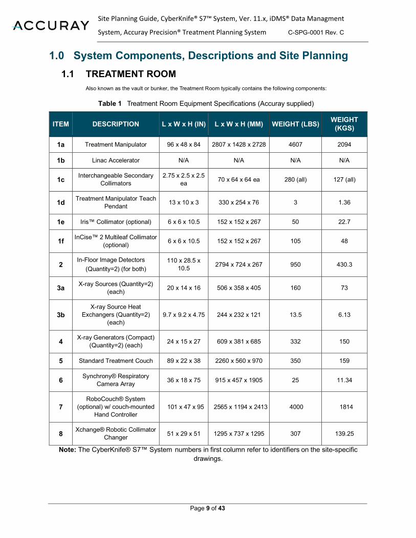
Also known as the vault or bunker, the Treatment Room typically contains the following components:
Table 1 Treatment Room Equipment Specifications (Accuray supplied)
ITEM DESCRIPTION L x W x H (IN) L x W x H (MM) WEIGHT (LBS) WEIGHT (KGS)
1a Treatment Manipulator 96 x 48 x 84 2807 x 1428 x 2728 4607 2094
1b Linac Accelerator N/A N/A N/A N/A
1c Interchangeable Secondary Collimators
2.75 x 2.5 x 2.5 ea 70 x 64 x 64 ea 280 (all) 127 (all)
1d Treatment Manipulator Teach Pendant 13 x 10 x 3 330 x 254 x 76 3 1.36
1e Iris™ Collimator (optional) 6 x 6 x 10.5 152 x 152 x 267 50 22.7
1f InCise™ 2 Multileaf Collimator (optional) 6 x 6 x 10.5 152 x 152 x 267 105 48
2 In-Floor Image Detectors
(Quantity=2) (for both) 110 x 28.5 x
10.5 2794 x 724 x 267 950 430.3
3a X-ray Sources (Quantity=2) (each) 20 x 14 x 16 506 x 358 x 405 160 73
3b X-ray Source Heat
Exchangers (Quantity=2) (each)
9.7 x 9.2 x 4.75 244 x 232 x 121 13.5 6.13
4 X-ray Generators (Compact) (Quantity=2) (each) 24 x 15 x 27 609 x 381 x 685 332 150
5 Standard Treatment Couch 89 x 22 x 38 2260 x 560 x 970 350 159
6 Synchrony® Respiratory Camera Array 36 x 18 x 75 915 x 457 x 1905 25 11.34
7 RoboCouch® System
(optional) w/ couch-mounted Hand Controller
101 x 47 x 95 2565 x 1194 x 2413 4000 1814
8 Xchange® Robotic Collimator Changer 51 x 29 x 51 1295 x 737 x 1295 307 139.25
Note: The CyberKnife® S7™ System numbers in first column refer to identifiers on the site-specific drawings.

Site Planning Guide, CyberKnife® S7™ System, Ver. 11.x, iDMS® Data Managment
System, Accuray Precision® Treatment Planning System C-SPG-0001 Rev. C
Page 10 of 43
Table 2 Xchange® Robotic Collimator Changer Table Weights
DESCRIPTION WEIGHT (LBS)
WEIGHT (KGS)
Fixed Collimator Housing 51 23.3
InCise™ Multileaf Collimator (optional) 112 51
Iris™ Collimator (optional) 67 30.5
All 12 Interchangeable Fixed Collimators 193 87.6
1.1.1 ACCURAY SUPPLIED (Required)
Treatment Manipulator (Item 1a – floor mounted) Description: A six-axis robot used for positioning and pointing the Linear Accelerator (linac) for patient treatment. Site planning considerations: The manipulator is bolted to a floor frame that is embedded in the floor concrete during the pre- installation process (See Section 5.1: Pre-Installation Process). Conduits will be installed from the floor frame to the Equipment Room (details will be shown on the site-specific drawings). The movement of the manipulator and linac within the room dictates room space requirements, including horizontal distances between finished walls and vertical distances between the finished floor and finished ceiling. See Section 3: Room Specifications for more information.
Linear Accelerator (linac) (Item 1b – mounted to the Treatment Manipulator) Description: The linac delivers the radiation treatment to the patient and utilizes a compact 6MV LINAC at 1000 MU/min. Site planning considerations: There are customer shielding considerations for the linac. Please see Section 2: Radiation Shielding Guidelines.
Interchangeable Secondary Collimators (Items 1c – the collimators reside in the Xchange® Table)
Description: Fixed Collimators are in diameters of 5.0, 7.5, 10.0, 12.5, 15.0, 20.0, 25.0, 30.0, 35.0, 40.0, 50.0, and 60.0 millimeters. Site planning considerations: These 12 collimators, plus additional solid and pinhole collimators, weigh approximately 16.1 pounds each (7.3 kg).

Site Planning Guide, CyberKnife® S7™ System, Ver. 11.x, iDMS® Data Managment
System, Accuray Precision® Treatment Planning System C-SPG-0001 Rev. C
Page 11 of 43
Treatment Manipulator Teach Pendant (Item 1d – wall mounted) Description: A wall-mounted remote-control device used to manually operate the Treatment Manipulator. Site planning considerations: A conduit will need to be installed from the mounting frame within the slab under the Treatment Manipulator through the concrete floor to the wall and then up the wall to a single gang electrical box on the wall, located at 48 inches (1.22 m) above finished floor. A cover with at least a 1” (25 mm) center hole should be provided for the box. Accuray will provide and install the wall-mounted bracket over the box on the wall at the time of the system installation.
In-Floor Image Detectors (Quantity=2) (Item 2 – floor mounted – at and below floor level)
Description: The detectors are used along with the X-ray Sources to correctly position the patient for treatment and to monitor patient positioning during treatment. Site planning considerations: The In-Floor Imaging Detectors are installed in an Accuray-supplied fiberglass tub that sits at and below floor level, with the top of the tub covers sitting flush with the finished floor. The fiberglass tub will be embedded in concrete during the pre-installation process (see Section 5.1: Pre-installation Process). It is important for the room’s finished flooring to fit up against the edges of the tub channel pieces so that the detector covers fit closely against the flooring for a finished look. See Accuray Incorporated’s site-specific drawings for more information on the relationships between the fiberglass tub, concrete floor, detector covers and the finished flooring.
X-ray Sources (Quantity=2) (Item 3a – ceiling mounted)
Description: The oil-cooled X-ray Sources are used as part of a larger system to track patient positioning. Site planning considerations: The X-Ray Sources are attached to the vault structural deck, via a Unistrut, above the imaging detectors. The Unistrut and related hardware used to support the X-ray Sources will be supplied by and attached to the vault structural deck by Accuray personnel during the pre-installation process (see Section 5.1: Pre-Installation Process). For a steel ceiling cap, the customer’s contractor will need to weld adaptor plates (supplied by Accuray) to the steel structural deck. For vaults with ceiling elevations 12 ft (3.66 m) or higher Accuray will install an extension kit for the Unistrut that includes cross bracing. Conduits [6 in (150 mm) and/or 4 in (100 mm)] from each X-ray Source to the X-ray Generators will need to be installed by the customer’s contractor. Details will be shown on the site-specific drawings. Accuray requires service access to the X-ray Sources and Unistrut. For servicing, Accuray recommends that the customer install an acoustical ceiling (or at minimum large access panels) in this area. Note: If the customer plans for a drywall ceiling, Accuray requires a 1 ft (30 cm) square access panel near the X-ray sources. If the space between the vault structural deck and finished ceiling is 1 ft (30 cm) or more, Accuray requires a 2 ft (60 cm) square access panel near the X-ray sources.

Site Planning Guide, CyberKnife® S7™ System, Ver. 11.x, iDMS® Data Managment
System, Accuray Precision® Treatment Planning System C-SPG-0001 Rev. C
Page 12 of 43
X-ray Source Heat Exchangers (Quantity=2) (Item 3b – ceiling mounted) Description: The heat exchangers are oil-based and are used to cool the X-ray Sources. Site planning considerations: The heat exchangers can be positioned almost anywhere against the vault structural deck or walls above the finished ceiling, as long as there is sufficient clearance for service and replacement. Due to cable length restrictions, they cannot be placed in the Equipment Room. Accuray will install mounting plates to the vault structural deck during the pre-installation process (see Section 5.1: Pre-Installation Process). The heat exchangers will be attached to the mounting plates during the system installation. Do not install HVAC, lighting or other components in locations that will interfere with the heat exchangers.
X-ray Generators (Quantity=2) (Item 4 – floor mounted) Description: These two cabinets supply high-voltage power to the X-ray Sources. Site planning considerations: The X-ray Generators may be located in either the Treatment or Equipment Room. Placement of the X-ray Generators is dependent on site-specific requirements.
Standard Treatment Couch (Item 5 – floor mounted) Description: The Standard Treatment Couch is used to position the patient during treatment using automatic patient positioning technology. The maximum patient weight load capacity of the Standard Treatment Couch is 350 lbs (159 kg). One couch pad and head base plate are included with this system. It is recommended that the site purchase a secondary couch pad for use with their CT unit. Site planning considerations: During the pre-installation process (see Section 5.1: Pre-Installation Process), Accuray will install a small conduit for providing cabling access from the imaging tub to the base of the table. During installation, Accuray will drill and anchor the couch to the floor.
Synchrony® Respiratory Camera Array (Item 6 – ceiling mounted)
Description: The Synchrony® Respiratory Camera Array is used to track, detect, and correct for respiratory motion. Site planning considerations: The Synchrony® Respiratory Camera Array is attached to a suspended rod mounted to the vault structural deck near the foot of the treatment couch. Accuray will install a plate to the concrete structural deck during the pre-installation process (see Section 5.1: Pre-Installation Process). A Steel structural deck requires the customer’s contractor to weld an adaptor plate, supplied by Accuray. Service access to the Synchrony camera and Unistrut are required. Customers should install an acoustical ceiling (or at minimum large access panels) in this area. Note: If the customer plans for a drywall ceiling, Accuray requires a 1 ft (30 cm) square access panel near the Synchrony® Respiratory Camera Array. If the space between the vault structural decking and finished ceiling is 1 ft (30 cm) or more, Accuray requires a 2 ft (60 cm) square access panel near the Synchrony® Respiratory Camera Array.

Site Planning Guide, CyberKnife® S7™ System, Ver. 11.x, iDMS® Data Managment
System, Accuray Precision® Treatment Planning System C-SPG-0001 Rev. C
Page 13 of 43
Emergency Power Components Description: The Emergency Power Off (EPO) switch (quantity=2) is an electrical switch that when pushed in an emergency will turn the power off to the entire CyberKnife® S7™ System. It is provided by Accuray and installed by the customer's contractor. Description: The Emergency Motion Off (EMO) switches (quantity=4) is an electrical switch that when pushed in an emergency will turn the power off to the Treatment Manipulator. It is provided by Accuray and Installed by the customer's contractor. Site planning considerations: The customer's contractor supplies and installs the electrical box, conduits and wiring for each EMO and EPO. All boxes are single gang electrical boxes, placed 48 in (1.22 m) above the finished floor. See Accuray site-specific drawings for desired locations.
Xchange® Robotic Collimator Changer (Item 8 – floor mounted) Description: The Xchange Table houses the fixed collimators, the Iris™ Collimator and the InCise™ MLC, (if applicable). It is positioned near the Treatment Manipulator. Site planning considerations: A small conduit [2 in (50 mm)] and electrical box [6 in square (150 mm)] should be installed in the concrete floor for the Xchange Table as shown on the site-specific drawings Note: Due to light sensitivity, lights should not be placed in the ceiling directly above the Xchange Table as indicated on the Accuray site-specific drawings.
1.1.2 ACCURAY SUPPLIED (Optional)
InCise™ Multileaf Collimator (Item 1f – stored on the Xchange Table) Description: Uses tungsten leaf pairs to shape the beam, using Non-Coplanar beam targeting. Site planning considerations: N/A
Iris™ Variable Aperture Collimator (Item 1e – stored on the Xchange Table) Description: Uses tungsten leaves to rapidly manipulate beam geometry. Site planning considerations: N/A
RoboCouch™ Patient Positioning System (Item 7 – floor mounted) Description: The RoboCouch® Patient Positioning System is used to position the patient during treatment using automatic patient positioning technology. The maximum patient weight load capacity of the RoboCouch® is 500 lbs (227 kg). One couch pad and head base plate is included with this system. Site planning considerations: The RoboCouch® Patient Positioning System bolts to a floor frame that is embedded in concrete during the pre-installation process. Accuray will install the RoboCouch floor frame at all customer sites, regardless of whether the option has been purchased. This minimizes future construction and associated costs if the option is purchased at a later date. A 6 in (150 mm) conduit is

Site Planning Guide, CyberKnife® S7™ System, Ver. 11.x, iDMS® Data Managment
System, Accuray Precision® Treatment Planning System C-SPG-0001 Rev. C
Page 14 of 43
required from the RoboCouch floor frame to the Equipment Room pull box. Details will be shown on the site-specific drawings.
1.1.3 CUSTOMER SUPPLIED ITEMS (Required) Hands-free Patient Intercom
See Section 5.6: Intercom
Closed Circuit TV (CCTV) Cameras See Section 5.7: Closed Circuit TV (CCTV) System
Information Technology (I.T) Please refer to the Accuray Incorporated’s CyberKnife I.T. Guide. Accuray’s Project Manager will provide this document to you.
1.1.4 CUSTOMER SUPPLIED (Optional) (unless required by local regulations)
Patient Positioning Lasers
See Section 5.5: Patient Positioning Lasers Nurse Call Button(s) Adequate Storage
Storage for QA tools, Synchrony® Respiratory vests, patient masks and body immobilization devices should be taken into consideration. The site-specific drawings will indicate areas in the Treatment Room where it is acceptable to install sinks and cabinets.
Sink: Used for patient prep and QA equipment Medical Gas Lines
Customers may elect to install medical gas and vacuum outlets directly in the Treatment Room or use mobile gas carts. Some patients, especially children, may require anesthesia. Please consult with the site administrator and/or physicians to determine the exact needs. These installations may include: • Oxygen
• Air • Nitrous Oxide
• Vacuum • Waste Anesthetic Gas Disposal

Site Planning Guide, CyberKnife® S7™ System, Ver. 11.x, iDMS® Data Managment
System, Accuray Precision® Treatment Planning System C-SPG-0001 Rev. C
Page 15 of 43
1.2 CONTROL ROOM The Control Room can be configured in many ways, depending upon the site layout and desire of the customer. Typically, it includes the following equipment:
1.2.1 ACCURAY SUPPLIED User Control Console, Synchrony & System Administrative Workstation
(Item 9, 10 & 12 – placed on a desktop or countertop) Description: This console consists of a dual LCD flat panel monitors, keyboard, and mouse.
LINAC Control Panel (Emergency Motion Off (EMO)) Panel (Item 11 – placed on a desktop or countertop) Description: This control box sits on the Control Room countertop, within easy reach of the operator. Their overall measurement is 15 in wide x 10 in deep x 6 in high (381 mm x 254 mm x 152 mm).
EPO (Emergency Power Off) Push Button Description: The EPO push button is supplied by Accuray and is installed by the Customer’s contractor. It should be installed in the wall near the linac Control Panel.
1.2.2 CUSTOMER SUPPLIED (Required)
Phone with Long Distance Access The phone is used for routine service and emergency communication. The phone number should be provided to Accuray prior to the installation.
Hands-free Main Intercom See Section 5.6: Intercom
Closed Circuit TV (CCTV) Monitoring System See Section 5.7: Closed Circuit TV (CCTV)
Door Interlock To be used in conjunction with the Treatment Vault door. Accuray requires two redundant door switches that is wired back to the dry contact located in the Equipment Room’s CIB box. See site specific drawings for more information.
Customer Network Data Port with Internet Access To be used by Accuray personnel during system installation and service activities.
Emergency Components “X-ray On” light positioned above the Treatment Room door. The customer supplies all the materials related to this light, including power. Accuray will supply the signal to the light via the CIB in the equipment room.

Site Planning Guide, CyberKnife® S7™ System, Ver. 11.x, iDMS® Data Managment
System, Accuray Precision® Treatment Planning System C-SPG-0001 Rev. C
Page 16 of 43
Physics Conduit Port (Dosimetry Tube) into the Treatment Room This port is used for running QA and Commissioning tools and equipment cables between the Control Room and Treatment Room. It is typically a 4 in (100 mm) conduit that runs from the top of the Control Room desk to the lower wall of the Treatment Room at a 45-degree angle, both vertically and horizontally, with access boxes and/or doors on either end.
1.3 EQUIPMENT ROOM The Equipment Room is located adjacent to or close to the shielded walls of the Treatment Room and is intended to hold the bulk of support equipment needed for the CyberKnife® S7™ System. The distance from the Equipment Room to both the Treatment and Control Rooms is limited by the maximum cable lengths allowed between system components.
1.3.1 ACCURAY SUPPLIED
Table 3 Equipment Room Equipment Specifications
DESCRIPTION L x W x H (IN) L x W x H (MM) WEIGHT (LBS)
WEIGHT (KGS)
13 Controller for Treatment Manipulator 23 x 32 x 61 584 x 813 x 1550 407 185
14 AMM (Modulator) 40 x 32 x 82 1020 x 808 x 2080 1162 528
15 Computer Rack (includes iDMS,
Gateway, and Core Network hardware)
38 x 25 x 71 965 x 635 x 1803 672 305
16 Power Distribution Unit (PDU) 38 x 25 x 51 965 x 635 x 1295 957 434
17 Mechanical Rack 38 x 25 x 71 965 x 635 x 1803 530 240
18 Controller (for optional RoboCouch™ System) 24 x 31 x 61 600 x 790 x 1550 330 150
Note: There are operating, and service clearances required around this equipment.
Controller (for the Treatment Manipulator) (Item 13 – floor mounted)
Modulator (Item 14 – floor mounted (with brackets to concrete))
Computer Rack (Item 15 – floor mounted)
Power Distribution Unit (PDU) Rack (Item 16 – floor mounted) Customer Interface Box (CIB)
This is a standard electrical wall box, approximately 12” x 12” x 4” (LxWxH) (300 mm wide x 300 mm tall x 100 mm deep) with a 24-point terminal strip inside. One side of the terminal strip is for wiring the EPOs, EMOs, “X-ray On” light, and Door switch (normally open/dry contacts) circuitry. These connections are made by the customer’s

Site Planning Guide, CyberKnife® S7™ System, Ver. 11.x, iDMS® Data Managment
System, Accuray Precision® Treatment Planning System C-SPG-0001 Rev. C
Page 17 of 43
electrician in accordance with the Accuray site-specific drawings. Located on the other side of the terminal strip is the wiring leading to the emergency circuitry (ESCC) within the CyberKnife® S7™ System. These connections are made by Accuray Installation Engineers.
Mechanical Rack (Item 17 – floor mounted) The mechanical rack includes the chiller, which is self-contained (does not require a chilled water source for operation). Note: This equipment can either sit on the floor (on its rollers),or be anchored to the concrete slab as required by OSHPD or other seismic requirements.
Customer Network Data Port with Internet Access To be used by Accuray personnel during system installation and service activities.
1.3.2 ACCURAY SUPPLIED (Optional) Controller (for the optional RoboCouch® System) (Item 18 – floor mounted)
If the Standard Treatment Couch has been purchased, the controller is not needed. However, in anticipation of any potential future upgrade to the RoboCouch System, we recommend that adequate floor space be available.
1.3.3 CUSTOMER SUPPLIED (required) Main Power Disconnect
See Section 4.1: Electrical Requirements.
Air Conditioning Unit See Section 4.2: Environmental Requirements.
Cable Management System We typically recommend a triple-tier cable tray system to be installed around the perimeter of the room, with the lowest point of the trays are either at 75 in (1900 mm) or 12 in (300 mm) above the finished floor. See the site-specific drawings for the required location in the Equipment Room. Other types of cable management systems can work as well. Please contact your Accuray Project Manager for alternate solutions.
Network Drops Please refer to the CyberKnife S7 System I.T. Guide provided by the Accuray Project Manager.
1.3.4 CUSTOMER SUPPLIED (recommended) Power Conditioner (Voltage Stabilizer) See Section 4.1: Electrical Requirements.

Site Planning Guide, CyberKnife® S7™ System, Ver. 11.x, iDMS® Data Managment
System, Accuray Precision® Treatment Planning System C-SPG-0001 Rev. C
Page 18 of 43
1.4 TREATMENT PLANNING ROOM(S) Treatment Planning can be located anywhere and configured in many ways, depending upon the site layout and customer preference. It is important that this room be ready for equipment and set up prior to system installation. Typically, the Treatment Planning room includes the following equipment:
1.4.1 ACCURAY SUPPLIED Accuray Precision® Treatment Planning System
(Item 19 – placed on a desktop or countertop) The CyberKnife® S7™ System’s standard configuration comes with 2 Accuray Precision Treatment Planning System Workstations that are normally located in a Treatment Planning Room or Physicist’s office. However, they can be located in the Control Room or any other location that has direct access to the CyberKnife® S7™ System network, facility network or Internet. Additional units can be purchased by the customer.
Color Laser Printer (Item 20 - placed on a desktop or countertop)
1.4.2 CUSTOMER SUPPLIED Network Drops
Please refer to the CyberKnife S7 System I.T. Guide provided by the Accuray Project Manager.

Site Planning Guide, CyberKnife® S7™ System, Ver. 11.x, iDMS® Data Managment
System, Accuray Precision® Treatment Planning System C-SPG-0001 Rev. C
Page 19 of 43
2.0 Radiation Shielding Guidelines 2.1 INITIAL SITE PLANNING
Primary barrier thicknesses will likely be between 48 and 60 in (1219 to 1524 mm) of standard density concrete (2.4 g/cm3 nominal density), depending upon workload, limits, occupancy factors and local regulations. In general, all walls are considered primary barriers with a 5% use factor for fixed and iris collimators and a 7.5% use factor for the multileaf collimator. For initial site planning, we recommend using 60 in (1524 mm) on all primary barriers with adjacent public areas. We recommend using 42 in (1067 mm) on all secondary barriers, including the ceiling. For specific shielding guidelines, please see the sections below. Note: The customer is ultimately responsible for determining the proper shielding for the Treatment Room and ensuring compliance with all local, state and country regulations.
2.2 RADIATION SHIELDING FOR THE CYBERKNIFE® S7™ SYSTEM 2.2.1 SYSTEM DESCRIPTION
The CyberKnife® S7™ System utilizes a compact X-band linac mounted on a robotic manipulator arm. The CyberKnife® S7™ System delivers dose from paths that are composed of a series of nodes. The specific nodes and positions of those nodes are determined when planning a CyberKnife® S7™ System treatment. During treatment delivery, the manipulator will move the accelerator from node to node in series while dose is delivered at only those nodes selected during the treatment planning process. The total number of nodes varies from 102-180 based on secondary collimator assembly (Fixed, Iris or MLC) and anatomical region treated (head or body/spine). There are 102 body path nodes using the MLC and 117 body path nodes using the Fixed or Iris collimator. Regarding head path nodes, there are 171 for MLC and 180 for Fixed/Iris. Figure 1 (next page) shows all possible node positions.
2.2.2 PERMISSIBLE EXPOSURE LIMITS – INTEGRATED VS. INSTANTANEOUS DOSE RATE LIMITS
Typically, integrated dose rate limits are used for radiation therapy facility barrier design: 20 µSv per week for uncontrolled areas and 100 µSv per week for controlled areas. Due to the low use factor of the CyberKnife® S7™ System, barrier design for integrated dose limits may have areas with high instantaneous dose rates. Accuray recommends consideration should be given to incorporating a 2 mrem (20 µSv) dose “in any one hour” limitation for public areas such as has been adopted by many regulatory authorities.
2.2.3 NOMINAL TREATMENT DISTANCE The CyberKnife® S7™ System is not an isocentric treatment device. However, a room imaging center (also called alignment center) is identified, which is where the beams of the two diagnostic imaging sources intersect. The treatment volume is rarely at the room isocenter but is usually within 10 cm of the room isocenter. Treatment distances for head path cases contain nodes with SAD ranging from 650 mm – 900 mm. Treatment distances for spine and body cases range from 800 mm – 1200 mm SAD.

Site Planning Guide, CyberKnife® S7™ System, Ver. 11.x, iDMS® Data Managment
System, Accuray Precision® Treatment Planning System C-SPG-0001 Rev. C
Page 20 of 43
Figure 1 Possible Node Configurations for CyberKnife® S7™ System S7™
The two objects shown above the Treatment Manipulator and linac are diagnostic X-ray sources (kV imagers). Images from these sources are used to determine patient position prior to and during treatment. During treatment delivery, the kV imaging system acquires images at treatment nodes that are used to determine patient position. This information is relayed to the manipulator system and any necessary corrections are made prior to treatment beam delivery.
2.2.4 CYBERKNIFE® S7™ SYSTEM SPECIFICATIONS
Beam Energy/ Output Rates 6 MV/ 1000 MU per minute (at 80 cm SAD) Reference Calibration Condition 1 MU is nominally equal to 1 cGy at 800 mm SAD, using a 60
mm diameter secondary collimator and at 15 mm depth in water
Field Size Fixed Collimator Assembly 12 collimators are available producing circular fields ranging from 5 mm to 60 mm at 800 mm SAD
Field Size Iris™ Collimator The Iris collimator is designed to closely replicate the twelve fixed collimator aperture sizes.
Field Size InCise™ Multileaf Collimator (MLC)
The variable aperture LMC has a maximum field size of 9.75 cm x 11 cm at 800 mm SAD
Table 4 CyberKnife® S7™ System S7 Specifications
2.2.5 WORKLOAD ESTIMATION The following table includes recommendations for estimating the workload of a CyberKnife® S7™ System for shielding design purposes. Recommended treatment times are based on clinical experience by expert users and Accuray simulations. For shielding purposes, the estimated treatment doses should be scaled to one meter and a TPR value of 0.7 should be assumed. However, the actual TPR values vary from 0.62 - 0.67 for the 60 mm fixed collimator (M6 TPR 20,10).

Site Planning Guide, CyberKnife® S7™ System, Ver. 11.x, iDMS® Data Managment
System, Accuray Precision® Treatment Planning System C-SPG-0001 Rev. C
Page 21 of 43
Table 5 Workload Estimations
Head Treatments
Fixed Collimator
Iris™ Collimator
InCise™ MLC
Average Treatment Time per Fraction
51 minutes
34 minutes
22 minutes
Average Fraction: 800 cGy @ 800 mm SAD Dose and Distance
Spine/Body Treatments
Fixed Collimator
Iris™ Collimator
InCise™ MLC
Average Treatment Time per Fraction 53 minutes 35 minutes 23 minutes
Average Fraction: 970 cGy @ 1000 mm SAD Dose and Distance Note: Actual treatment times may vary and are largely dependent on treatment planning.
Example: Estimate the primary weekly workload at the nominal treatment distance (80 cm) for a facility that intends to treat 4 head cases and 4 spine/body cases per day, 5 days per week:
4 head treatments per day * 8.0 Gy / fraction * (0.8 m / 1.0 m)2 * 5 days / week = 102.4 Gy / week 4 spine/body treatments per day * 9.7 Gy / fraction * 5 days / week = 194 Gy / week
Total primary weekly workload at 100 cm = 296.4 Gy / week Note: Workload estimations are site specific and shielding design calculations may differ from
country to country.
2.2.6 USE & MODULATION FACTORS
The CyberKnife® S7™ System can direct primary beams at all walls and at the floor. Accuray recommends a primary barrier use factor of 5% for fixed and iris collimators and 7.5% for the multileaf collimator. The beam can be directed upward at a maximum angle of 18° above the horizontal. For most facilities this means that the ceiling is a secondary barrier. Accuray recommends a modulation factor (MU per cGy) of 15 for Fixed and Iris collimators and 7 for the multileaf collimator. Figure 2 below shows the target location and reference axis for a CyberKnife® S7™ System S7™ System.

Site Planning Guide, CyberKnife® S7™ System, Ver. 11.x, iDMS® Data Managment
System, Accuray Precision® Treatment Planning System C-SPG-0001 Rev. C
Page 22 of 43
Figure 2 Linac dimensions (mm) from key components pertinent to shielding design.
2.2.7 TENTH VALUE LAYERS (TVLs)
Rogers, et al. have used Monte Carlo techniques to estimate TVLs (primary beam) for use with the CyberKnife® S7™ System. Accuray recommends using the equilibrium values (TVLe) from the table below.
TVL data
Concrete Lead
Density (g/cm3) 2.35 2.35 11.34 11.34
SDD (m) 4.8 6.8 3.3 5.3
TVL1 (cm) 29.4 31.2 4.8 5.1
TVLe (cm) 31.9 32.4 5.05 5.25
TVL data for ordinary concrete and lead. Ordinary concrete composition NBS04 as given by Rodgers.4
2.2.8 SECONDARY RADIATION (LEAKAGE & SCATTER) Secondary radiation shielding considerations typically include components of both system leakage and
patient scatter. However, for the CyberKnife® S7™ System® S7™ linac, secondary barrier thickness requirements from patient scatter are negligible compared to the requirements from leakage radiation,
even when considering larger field sizes and greater workloads from the Multileaf Collimator. The CyberKnife® S7™ System is shielded to limit leakage radiation around the linac head and within the

Site Planning Guide, CyberKnife® S7™ System, Ver. 11.x, iDMS® Data Managment
System, Accuray Precision® Treatment Planning System C-SPG-0001 Rev. C
Page 23 of 43
patient plane. Patient plane leakage fractions do not exceed 0.1% and typically average below 0.05% of the reference dose (1000 cGy/min at 800 mm SAD using a 60 mm diameter secondary collimator at a
depth of 15 mm in water). Maximum values for leakage radiation at a distance of 1 meter from the electron beam path do not exceed 0.1% of the reference dose. The maximum values are typically
measured in the front of the linac head, in the target plane at one meter from the reference axis. Both leakage and TVL values are smaller around the back, sides and top of the linac. Leakage TVLe around
the rest of the LINAC is 29.2 +/- 0.4 cm of concrete. Typically, only 50% of the leakage dose value is comprised of radiation that is of sufficient energy to penetrate more than one TVL of concrete. See
Accuray Shielding White Paper P/N 500627.A for details on the use of “high energy leakage” value for shielding calculations.
2.2.9 GROUNDSHINE RADIATION Groundshine radiation may be a problem under any direct shielded doors or secondary shielded walls. Refer to Page 82 of the NCRP report 151 mentioned below for more information.
2.2.10 CYBERKNIFE® S7™ SYSTEM SHIELDING PUBLICATIONS NCRP report 151 has dedicated sections on CyberKnife® S7™ System shielding (section 5.7 and section 7.2). http://www.ncrppublications.org

Site Planning Guide, CyberKnife® S7™ System, Ver. 11.x, iDMS® Data Managment
System, Accuray Precision® Treatment Planning System C-SPG-0001 Rev. C
Page 24 of 43
3.0 Room Specifications 3.1 TREATMENT ROOM
3.1.1 TREATMENT ROOM SIZE SPECIFICATIONS
The CyberKnife® S7™ System has two primary orientations:
• Option 1 - 45° Xchange® CyberKnife® S7™ System Vault layout (5 options) • Option 2 - 90° Xchange CyberKnife® S7™ System Vault layout (6 options)
Figure 3 Option 1- 45° Xchange CyberKnife® S7™ System Vault Layout

Site Planning Guide, CyberKnife® S7™ System, Ver. 11.x, iDMS® Data Managment
System, Accuray Precision® Treatment Planning System C-SPG-0001 Rev. C
Page 25 of 43
Figure 4 Option 2- 90° Xchange CyberKnife® S7™ System Vault Layout
3.1.2 RECOMMENDED EQUIPMENT ORIENTATION WITHIN THE TREATMENT ROOM
Your Accuray Project Manager will help to determine the optimal orientation for your CyberKnife® S7™ System based on:
• Ease of patient loading • Exact system configuration
• System clearances • Shielding considerations
• Ease of access to sinks and cabinets
• Customer preferences
Your Accuray Project Manager will address any questions, related to the above during the design process.
Site Planning Guide, CyberKnife® S7™ System, Ver. 11.x, iDMS® Data Managment
System, Accuray Precision® Treatment Planning System C-SPG-0001 Rev. C
Page 26 of 43
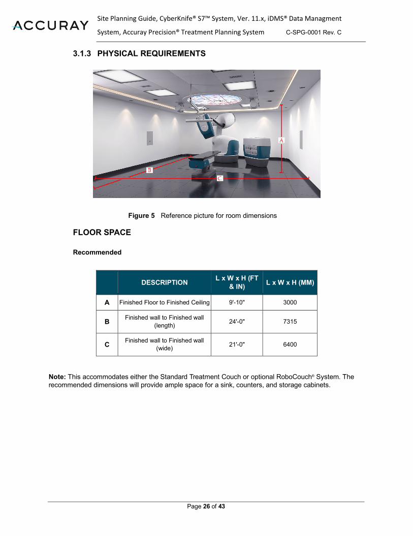
3.1.3 PHYSICAL REQUIREMENTS
Figure 5 Reference picture for room dimensions
FLOOR SPACE
Recommended
DESCRIPTION L x W x H (FT & IN) L x W x H (MM)
A Finished Floor to Finished Ceiling 9'-10" 3000
B Finished wall to Finished wall (length) 24'-0" 7315
C Finished wall to Finished wall (wide) 21'-0" 6400
Note: This accommodates either the Standard Treatment Couch or optional RoboCouch® System. The recommended dimensions will provide ample space for a sink, counters, and storage cabinets.

Site Planning Guide, CyberKnife® S7™ System, Ver. 11.x, iDMS® Data Managment
System, Accuray Precision® Treatment Planning System C-SPG-0001 Rev. C
Page 27 of 43
Absolute Minimum
DESCRIPTION L x W x H (FT & IN) L x W x H (MM)
A Finished Floor to Finished Ceiling 9'-7" 2920
B Finished wall to Finished wall (length) 21'-0" 6400
C Finished wall to Finished wall (wide) 15'-10" 4830
Note: The absolute dimensions will accommodate either the Standard or RoboCouch® System and limited space for the sink, counter and storage.
The equipment within the Treatment Room does not take up the entire square footage as noted above, but does use most of the space within this area depending upon the configuration of the system. The Accuray site-specific drawing CK-A1 will show the customer where it is safe to install sinks, cabinets and other pieces of customer supplied equipment within the room.
The dotted lines on site-specific Drawing CK-A1 identify the required clearance areas for robotic movement. The clearance paths must not intersect with any wall, column, or other obstruction.
The room dimensions mentioned above only include the floor space of the actual Treatment Room and do not include any floor space dedicated to a maze or the swing path of a direct-shielding door.
3.1.4 Vault Structural Deck Height:
Recommended: 11 ft or greater (3.35 m or greater) height between finished floor and vault structural deck (whether concrete or steel) allows for the installation of electrical and mechanical components.
Absolute Minimum Finished Ceiling Height:
9 ft-7 (A) in (2.9 m) height between the finished floor and the finished ceiling within the robotic movement path as noted on CK-A1 in the site specific drawings.
Recommended Finished Ceiling Height:
9 ft-10 (A) in (3.0 m) height between the finished floor and the finished ceiling within the robotic movement path as noted on CK-A1 in the site-specific drawings.
Fixed Rule about Ceiling Height (if optional RoboCouch® Patient Positioning System has been purchased)

Site Planning Guide, CyberKnife® S7™ System, Ver. 11.x, iDMS® Data Managment
System, Accuray Precision® Treatment Planning System C-SPG-0001 Rev. C
Page 28 of 43
The capped free-standing cover is capped at 7’-11” (2.4 m) tall.
RoboCouch® Patient Positioning System Column Cover
Note: The capped free-standing cover is the default cover for the RoboCouch® System. Typically, the extended free-standing cover is only used in situations where the electrical cables must be routed through the ceiling.
MINIMUM DOOR CLEARANCE
4’ wide x 7’ tall (1220 x 2134 mm)
Recommended Minimum Clearances: 6’ wide x 7’ tall (1524 x 2134 mm).
Note: If the vault door is narrower than 52", some parts of the RoboCouch need to be removed to fit through.
3.2 CONTROL ROOM MINIMUM FLOOR SPACE 100 square ft (9.3 square m), will provide adequate counter space for at least 2 people and 3-4 workstations.
3.2.1 RECOMMENDED LOCATION The Control Room should be located within view of the Treatment Room door and should be designed in accordance with the facility patient privacy policy.
3.2.2 MINIMUM DOOR CLEARANCE Standard door clearances are acceptable for moving equipment into the Control Room.
Note: If the Equipment Room is accessed through the Control Room, both doors must be 3 ft wide x 7 ft high (.914 m x 2.134 m) for rigging the equipment into the Equipment Room, door clearances for the rig path need to be the United States standard measurement of 82 in-83 in.
Site Planning Guide, CyberKnife® S7™ System, Ver. 11.x, iDMS® Data Managment
System, Accuray Precision® Treatment Planning System C-SPG-0001 Rev. C
Page 29 of 43
3.3 EQUIPMENT ROOM
3.3.1 RECOMMENDED FLOOR SPACE
175 square ft (16 square m) if the X-ray Generators are in the Equipment Room.
155 square ft (14.5 square m) if the X-ray Generators are located outside of the Equipment Room.
Note: No wall in the Equipment Room should be less than 7 ft (2.1 m) long, to provide adequate installation and service access to the equipment.
3.3.2 FIXED RULE ABOUT FLOOR SPACE Additional floor space must be built into the Equipment Room for any customer-supplied equipment, such as transformers, UPS, battery cabinet, power conditioners (voltage stabilizers), floor-mounted air conditioning units, data and server equipment, phone equipment, storage cabinets, etc. Service access and regulatory requirements must be considered when planning for adequate space around each piece of Accuray or customer-supplied equipment.
3.3.3 RECOMMENDED LOCATION
Due to limited cable lengths between most equipment, the Equipment Room should be located adjacent to the Treatment Room and as close to the Treatment Manipulator as possible.
Note: As a general rule, the maximum cable length from the Treatment Manipulator (1a) to the Equipment Room pull box (PB1) should not exceed 30 ft (9.1 m). System operators must be able to access the Equipment Room during patient treatment. The CyberKnife components (with the exception of the X-ray Generators) cannot be located in the Treatment Room, assessable from the Treatment Room, or on a different floor. Stacking components is not permissible.
3.3.4 MINIMUM FINISHED CEILING CLEARANCE
7 ft (2.135 m) between finished floor and finished ceiling.
3.3.5 MINIMUM DOOR CLEARANCE
3 ft wide x 7 ft high (.914 m x 2.134 m).
Note: The Equipment Room door(s) must be kept locked and accessible only by trained operators.
3.4 TREATMENT PLANNING ROOM(S) WORKSPACE
Provide adequate workspace for two or more workstations and a desktop color laser printer. Accuray will show the exact number of purchased workstations on the customer site-specific drawings if the information is available. Otherwise, a generic workspace will be shown.

Site Planning Guide, CyberKnife® S7™ System, Ver. 11.x, iDMS® Data Managment
System, Accuray Precision® Treatment Planning System C-SPG-0001 Rev. C
Page 30 of 43
3.4.1 RECOMMENDED LOCATION
The Treatment Planning Room can be located anywhere in the facility. The distance between the Treatment Planning Room and the Equipment Room will determine which network cabling option is required. Please see the IT section of this document, or Accuray Incorporated’s CyberKnife® S7™ System I.T. Guide, for more information.
3.5 SAMPLE DRAWINGS The following two illustrations show two typical floor plan layouts. For a complete package of sample drawings and design details, please contact your Accuray Site Planner.
Figure 6 Typical CyberKnife® S7™ System® Floor Plan with Maze
Key: A = Treatment Room (Vault) B = Equipment Room C = Control Room D = Treatment Planning Room

Site Planning Guide, CyberKnife® S7™ System, Ver. 11.x, iDMS® Data Managment
System, Accuray Precision® Treatment Planning System C-SPG-0001 Rev. C
Page 31 of 43
Figure 7 Typical CyberKnife® S7™ System Floor Plan with Direct Shielded Door
Key A = Treatment Room (Vault) B = Equipment Room C = Control Room D = Treatment Planning Room Note: For additional example drawings (in AutoCAD or PDF format), please contact your Accuray Project Manager.
4.0 Electrical and Environmental Requirements 4.1 ELECTRICAL
POWER REQUIREMENTS It is recommended to supply 480 VAC, 3-phase, 100 Amps, 55 kVA power to the Main Power Disconnect. However, the system’s Power Distribution Unit (PDU) will accept input power in the range of 200 VAC through 480 VAC. For any input voltages at 240 VAC and below, 150 Amps is required. The PDU input shall be configurable from one of the following voltages: 200/208/240/380/400/415/400/415/440/480 +/- 2%
The Main Power Disconnect typically needs a 36 in square (914 square mm) exclusionary area directly in front of it for regulatory requirements. We recommend that it be located next to the door of the Equipment Room. The customer is responsible for the Main Power Disconnect, fuses and all conduits and wiring from the original power source to the disconnect. Accuray will supply and run the power cable from the Main Power Disconnect to the system’s PDU. The CyberKnife® S7™ System does not use a neutral leg. A grounding lug is to be supplied by the electrical contractor with the following specifications: A 1/0-gauge lug terminating to grounded building steel or earth ground within the Main Power Disconnect.
The Main Power Disconnect can be located on an outside wall of the Equipment Room, as long as it remains within the cable limitations of the PDU.

Site Planning Guide, CyberKnife® S7™ System, Ver. 11.x, iDMS® Data Managment
System, Accuray Precision® Treatment Planning System C-SPG-0001 Rev. C
Page 32 of 43
POWER CONDITIONER (VOLTAGE STABILIZER) A power conditioner will be required of the customer if the input voltage cannot be regulated to within +/- 5% phase to phase. The technical analysis and choice of power conditioner is the responsibility of the customer.
UNINTERRUPTABLE POWER SUPPLY (UPS) A UPS is provided by Accuray to power the Treatment Delivery System, Data Server, LCD monitor and networking devices in the event of a power failure to reduce risk of data or damage.
A UPS is not provided for other workstations, such as the Accuray Precision® Treatment Planning System Workstation, Accuray Precision® MD Suite Workstation or other remote workstations. Although not required, the customer may, at their discretion and expense, provide additional UPS for protection.
4.2 ENVIRONMENTAL 4.2.1 GENERAL REQUIREMENTS
All CyberKnife® S7™ System Equipment is rated to operate at pressures ranging from 103 to 65 kPa (equivalent to -150 m to 3,800 m ( -500 ft to 12,500 ft) elevation), and can tolerate a temporary exposure to pressures of 103 to 56 kPa (equivalent to -150 m to 5,000 m (-500 ft to16,400 ft) elevation) while not in operation. All CyberKnife® S7™ System Equipment is rated to operate at temperatures ranging from 10° to 35° C (50° to 95°F), and can tolerate temporary exposure to a temperature range of -30° to 50° C (-22° to 122° F) while not in operation. All CyberKnife® S7™ System Equipment is rated to operate at humidity levels ranging from 30% - 75%, non-condensing, and can tolerate a temporary exposure to a humidity range of 10% to 90%, non-condensing, while not in operation.
4.2.2 TREATMENT ROOM The Treatment Room should be kept between 50° F and 75° F (10° C and 23.9° C),24 hrs/7 days, with a range of 30 to 75% non-condensing relative humidity. The following table identifies the heat generated by the equipment in the Treatment Room:
Item Description BTU/h KILOWATT
1a Treatment Manipulator 0 0
1b Linear Accelerator
0
0
1c Interchangeable Secondary Collimators
0
0
1d Treatment Manipulator Teach

Site Planning Guide, CyberKnife® S7™ System, Ver. 11.x, iDMS® Data Managment
System, Accuray Precision® Treatment Planning System C-SPG-0001 Rev. C
Page 33 of 43
Pendant 0 0
1e Iris™ Collimator (Optional)
0
0
1f InCise™ Multileaf Collimator (optional)
0
0
2 In-Infloor Image Detectors (Qty=2)
1230 0.36
3a X-ray Sources
(Quantity=2)
0
0
3b X-ray Source Heat Exchangers (Quantity=2)
2400
0.7
4 X-ray Generators (Quantity=2) (may be located in another room)
1100
0.322
5 Standard Treatment Couch
0
0
6 Synchrony® Respiratory Camera Array
0
0
7 RoboCouch® System (Optional)
0
0
8 Xchange® Collimator Changer o o
Total without X-Ray Generators in Treatment Room
4730 btu 1.382 kw
Total with X-Ray Generators in Treatment room
3630 btu 1.06 kw
4.2.3 CONTROL ROOM
There are no special environmental requirements regarding the CyberKnife® S7™ System® in the Control Room.

Site Planning Guide, CyberKnife® S7™ System, Ver. 11.x, iDMS® Data Managment
System, Accuray Precision® Treatment Planning System C-SPG-0001 Rev. C
Page 34 of 43
4.2.4 EQUIPMENT ROOM The Equipment Room must be kept less than 70° F (21.1° C), with a range of 40-55%,relative non condensing, 24 hrs/ 7 days. The following table identifies the heat generated by the equipment in the Equipment Room:
Item Description BTU/h KILOWATT
4 X-ray Generators (Quantity=2) (may be located in another room)
1100 .322
13 Controller (for Treatment Manipulator) 4700 1.377
14 AMM (Modulator) 11600 3.4
15 Computer Rack (includes iDMS, Gateway, and Core Network hardware)
3800 1.114
16 Power Distribution Unit (PDU) Rack
2600
.762
17
Mechanical Rack
6300
1.85
18 Controller (for RoboCouch® System) 4700
1.377
Total Maximum Cooling Requirements 34,800 btu 10.2 kw
Note: Most customers install a minimum 4 ton HVAC unit to meet the mechanical requirements. Please see Section 4: Electrical and Environmental Requirement for more information.
4.2.5 TREATMENT PLANNING ROOM(S)
There are no special environmental requirements regarding the CyberKnife® S7™ System in the Treatment Planning Room(s).
4.3 NOISE LEVELS EQUIPMENT ROOM The customer may choose to incorporate noise reduction in the equipment room. The noise level is measured to be 90dB.
4.4 VIBRATION ANALYSIS The customer is responsible for any vibrational analysis required.

Site Planning Guide, CyberKnife® S7™ System, Ver. 11.x, iDMS® Data Managment
System, Accuray Precision® Treatment Planning System C-SPG-0001 Rev. C
Page 35 of 43
5.0 Other System Implementation Considerations
5.1 PRE-INSTALLATION PROCESS
5.1.1 ACCURAY PRE-INSTALLATION PROCESS
This process takes place prior to installation of the CyberKnife® S7™ System and is completed and coordinated by Accuray resources.
• Installation of the treatment manipulator frame and RoboCouch® Patient Positioning System frame.
• Installation of the imaging tub. • Installation of the X-Ray source mounts and heat exchanger mounts.
• Installation of the Synchrony® Respiratory Camera Array mount.
During the Pre-Installation process, access to the structural vault deck for anchoring the X-ray Source Unistrut plates, heat exchanger plates, and Synchrony® Respiratory Camera Array mounting plate is required. If the structural vault deck is steel, the Contractor is responsible for welding these components in place. Construction material and equipment should be removed from the vault to allow free movement of ladders, tools and equipment by Accuray personnel. The conduits for the Treatment Manipulator and RoboCouch® frames must be installed after the frames have been installed. The Treatment Vault must completely enclosed and free of all water and debris prior to the Pre-Installation process.
Contractor supplied equipment and labor:
• Ladder of sufficient height to do ceiling work (power lift for ceilings over 12 ft) • Electricity for hand tools (typically 120V/AC in the US, or equivalent internationally)
• Portable lighting for safe work
• Basic cooling/heating as necessary if temperatures are extreme • Dust ventilation as required.
• Additional labor (1-2 people) to help lift and install the floor frames onto the anchors • Dumpster for crates and debris.
5.1.2 SHIPPING AND RIGGING
The pre-installation kit is shipped to the customer based on the construction schedule. The Project Manager will coordinate in accordance with the contractor.
5.1.3 CONTENTS OF SHIPPING CRATES
For any rigging or storage purposes, the Pre-Installation Kit (PIK) crate measurements are typically:

Site Planning Guide, CyberKnife® S7™ System, Ver. 11.x, iDMS® Data Managment
System, Accuray Precision® Treatment Planning System C-SPG-0001 Rev. C
Page 36 of 43
Crate Contents Length Width Height Weight
large
Kit pre-install Synchrony® Respiratory Camera Array
Customer Interface Box
Frame hardware
Imaging tub and hardware
XRS hardware
Heat exchanger
127 in 3226 mm
44 in 1118 mm
33 in 838 mm
582 lbs 264 kgs
Medium Treatment Manipulator Frame 50 in
1270 mm 50 in
1270 mm 29 in
737 mm 655 lbs 297 kgs
Small RoboCouch® Patient Positioning System frame
52.5 in 991 mm
32 in 813 mm
24 in 737 mm
770 lbs 283 kgs
5.1.4 CONTRACTOR FOLLOW-UP WORK
The Contractor is responsible for the installation of all the conduits in the floor prior to pouring concrete. Avoid forcing concrete under the Imaging Tub and concrete should not be vibrated.
5.1.5 ADDITIONAL SITE WORK BY ACCURAY
After the pre-installation kit is installed, the Accuray Project Manager will:
• Inspect and measure all cable conduits to ensure lengths are per the drawings. • Provide the electrician with the Accuray supplied materials such as the Customer
Interface Box/EMO/EPO, ect…

Site Planning Guide, CyberKnife® S7™ System, Ver. 11.x, iDMS® Data Managment
System, Accuray Precision® Treatment Planning System C-SPG-0001 Rev. C
Page 37 of 43
5.2 SHIPPING AND RIGGING CONSIDERATIONS 5.2.1 CYBERKNIFE® S7™ SYSTEM
# Contents Dimension Weight
1 Treatment Manipulator 96 in x 60 in x 89 in 2438 mm x 1524 mm 2261 mm
3,836 lbs 1740 kgs
2 Controller 29 in x 38 in x 65 in 737 mm x 965 mm x 1651 mm
592 lbs 269 kgs
3 Standard System Cables / Sub System 46 in x 67 in x 29 in 1168 mm x 1702 mm x 1270 mm
418 lbs 190 kgs
4 System Covers 50 in x 94 in x 50 in 1270 mm x 2388 mm x1270 mm
650 lbs 184 kgs
5 System Covers 43 in x 79 in x 26 in 1092 mm x 2007 mm x 660 mm
296 lbs 134 kgs
6 Detector Base Frame 33 in x 115 in x 12 in 838 mm x 2921 mm x 305 mm
242 lbs 110 kgs
7 Double Bay Rack, Printer, Accuray Precision® Workstation
49 in x 86 in x 86 in 1245 mm x 2184 mm x 2184 mm
1,500 lbs 680 kgs
8 Chiller 37 in x 48 in x 64 in 940 mm x 1219 mm x 1626 mm
612 lbs 278 kgs
9 PDU 34 in x 42 in x 62 in 864 mm x 1069 mm x 1575 mm
1,176 lbs 533 kgs
10 AMM (Modulator and Linac boxes) 48 in x 86 in x 60 in 1220 mm x 2185 mm x 1524 mm
1,750 lbs 794 kgs
11 Linac Head 48 in x 86 in x 54 in 1220 mm x 2185 mm x 1375 mm
780 lbs 354 kgs
12 X-ray Sources and X- Ray Generators 48 in x 86 in x 60 in 1220 mm x 2185 mm x 1524 mm
1,238 lbs 562 kgs
13 Generator Covers and Detectors 49 in x 86 in x 60 in 1245 mm x 2184 mm x 1524 mm
630 lbs 286 kgs
14 Imaging Tub Components, lead shielding 47 in x 86 in x 39 in 1194 mm x 2184 mm x 991 mm
1,014 lbs 460 kgs
15 Ladder 32 in x 110 in x 20 in 813 mm x 2794 mm x 508 mm
150 lbs 68 kgs
16 QA Tools, Documentations and software 47 in x 66 in x 39 in 1194 mm x 1676 mm x 991 mm
372 lbs 169 kgs
17 Secondary Collimators 30 in x 20 in x 14 in 762 mm x 508 mm x 356 mm
170 lbs 77 kgs
18 RoboCouch® System 56 in x 82 in x 92 in 1422 mm x 2083 mm x 2337 mm
4000 lbs 1814 kgs
Table 1 CyberKnife® S7™ System Crate Measurements and Weights

Site Planning Guide, CyberKnife® S7™ System, Ver. 11.x, iDMS® Data Managment
System, Accuray Precision® Treatment Planning System C-SPG-0001 Rev. C
Page 38 of 43
5.2.2 SHIPPING AND RIGGING
The Accuray Project Manager will coordinate the schedule with the customer. The sales contract includes up to $8,000 (US Dollars) to cover shipping and rigging costs. Special rigging, such as premium hours, use of a crane or a nonstandard rig path can result in excess costs to be covered by the customer. The customer is required to provide a 30-yard dumpster for the first 2 days of installation for disposal of crating material. In addition, the customer should also provide ample storage space for the fiberglass covers during the first 2 weeks of installation. System arrives in standard tractor trailer with both back and side loading. Discuss parking, dock space and staging requirements with your Accuray Project Manager.
5.2.3 SYSTEM STORAGE (NON-OPERATING CONDITION) GUIDELINES
If the CyberKnife® S7™ System must be stored for any length of time in a crated or uncrated condition, please follow these guidelines:
• 400 square ft (37.2 square m) is needed for storing a full system
• Provide an environmentally protected indoor area free from dust and potential water damage.
• Ensure the area is temperature controlled between 50° F and 75° F (10° C and 23.9° C).
• Maintain less than 75% humidity, non-condensing. • Maintain a safe and secured environmental.
5.2.4 RIG-IN MANPOWER AND EQUIPMENT REQUIREMENTS
Manpower
• One experienced rigger, two additional movers. • Our installers will be present to help answer questions and assist where required.
Equipment
• One 10,000 lb (4536 kg) forklift with 8 ft (2.4 m) fork blades. • One electric two-ton pallet jack. • One hand-operated genie lift (>300 lbs capacity) (136 kg).
• One J-bar. • Eight (8) four-wheel dollies.
• Two metal plates for crossing doorways.
• Floor protection for the length of the route (masonite or lexan sheets 4 ft x 8 ft) (1.2 m x 2.4 m). The Treatment Manipulator, at 2,850 lbs (1,293 kg), is the heaviest piece to move.
• Basic tools for uncrating the equipment.

Site Planning Guide, CyberKnife® S7™ System, Ver. 11.x, iDMS® Data Managment
System, Accuray Precision® Treatment Planning System C-SPG-0001 Rev. C
Page 39 of 43
• Tarps to cover or “stage” the equipment if the weather is an issue.
• Straps
Note: Because the rig-in typically starts at 8:00 a.m., it is preferred that the rigging equipment be delivered the day before the system delivery. If this is not feasible, the equipment must be on site by 7:00 a.m. on the day of.
5.3 CT SCANNERS
The CyberKnife® S7™ System has been designed to deliver patient treatment with sub-millimeter accuracy. In order to ensure this highest level of patient care and treatment, the image data sets that are sent from the customer’s CT scanner(s) to the CyberKnife® S7™ System must follow specific guidelines:
Minimum Requirements
A minimum 16-slice CT scanner should be used for Synchrony® cases. This will assure reasonably short scan times, high image quality, minimal fiducial movement, and minimal artifact and movement stemming from patient breathing.
Minimum Requirements
No more than 1.5 mm slice thickness must be used to maximize treatment accuracy.
Note: Variable slice thickness cannot be used with the CyberKnife® S7™ System. 4D Software Option
If the customer has purchased Accuray Incorporated’s 4D software option, they must have a CT scanner with a 4D option, as well. The current CT scanners supported by this option are:
• GE Discovery ST
• Siemens Sensation Open
• Philips Brilliance Big Bore
Note: If your facility’s CT scanner(s) cannot meet any of the requirements listed above, or you have any questions about these guidelines, please contact your Accuray Project for more information.
5.3.1 CT OVERLAY KITS (CARBON FIBER TOP)
Each CT scanner used to supply image data sets to the CyberKnife® S7™ System must have a Carbon Fiber Flat Overlay for the CT cradle (typically required for Radiation Oncology), a 2 in (51 mm) thick pad and a CIVCO base plate. These items should be present on the CT scanner at the time of system installation. Manufacturer lead times can be as long as 12 weeks and therefore should be ordered well in advance of the installation. Overlay tops are not needed for other modalities used during treatment planning, such as MRI, Angio or PET imaging.

Site Planning Guide, CyberKnife® S7™ System, Ver. 11.x, iDMS® Data Managment
System, Accuray Precision® Treatment Planning System C-SPG-0001 Rev. C
Page 40 of 43
5.4 SULFUR HEXAFLUORIDE (SF6) GAS
Accuray requires a 60 lb (27.2 kg), 99.9% pure canister of SF6 gas to be onsite prior to system installation.
COMMON SUPPLIERS
• Concorde Specialty Gases, Inc. – www.concordegas.com • Praxair – www.praxair.com
Note: The SF6 gas is required to be onsite prior to the start of the system installation and will need to be ordered at least one month in advance.
5.5 PATIENT POSITIONING LASERS
Lasers are not necessary for use with the CyberKnife® S7™ System but are highly recommended. The customer is responsible for purchasing and installing lasers if they chose to have them.
Laser specifications are as follows: Two transverse and coronal lasers with the center line located 36-¼ in (920.75 mm) off the finished floor, one on each side of isocenter. The third laser should be a sagittal laser located 90 in (2286 mm) off the finished floor, at the foot of the patient couch, with the laser pointed down the center line of the couch top. The positions are called out on the Accuray site-specific drawings.
COMMON SUPPLIERS
• LAP – www.lap-laser.com • Gammex – www.gammex.com
Note: Lasers are installed and aligned after the CyberKnife® S7™ System has been installed.

Site Planning Guide, CyberKnife® S7™ System, Ver. 11.x, iDMS® Data Managment
System, Accuray Precision® Treatment Planning System C-SPG-0001 Rev. C
Page 41 of 43
5.5.1 INSTALLATION LOCATIONS
Figure 8 Laser Installation Locations
Key:
L1 = Laser crosshair centered 36-¼ in (921 mm) above finished floor
L2 = Laser beam centered 90 in (2286 mm) above finished floor.
5.6 INTERCOMS
The customer is responsible for purchasing and installing a hands-free intercom for use with the CyberKnife® S7™ System.
COMMON SUPPLIERS
• Aiphone – www.aiphone.com
Note: The intercom should be installed prior to the CyberKnife® S7™ System installation.

Site Planning Guide, CyberKnife® S7™ System, Ver. 11.x, iDMS® Data Managment
System, Accuray Precision® Treatment Planning System C-SPG-0001 Rev. C
Page 42 of 43
5.7 CLOSED CIRCUIT TV (CCTV)
The customer is responsible to provide and install a minimum of 4 dome cameras. A minimum of two with pan/tilt/zoom capabilities should be located in the ceiling. A quad multiplex monitor, keyboard and speaker to be located in the control room.
COMMON SUPPLIERS
• Nuvico – www.nuvico.com
5.8 QUALITY ASSURANCE AND COMMISSIONING TOOLS
Please consult Accuray Incorporated’s Physics Essentials Guide for the required Customer and Accuray provided QA Tools and Equipment. All of the required tools must be on site for the CyberKnife® S7™ System installation. Please go to https://www.accuray.com/services/site-planning-installation/ for eh Physics & QA Equipment and consult with your Customer Project Manager or Accuray Medical Physicist for specific requirements.

Site Planning Guide, CyberKnife® S7™ System, Ver. 11.x, iDMS® Data Managment
System, Accuray Precision® Treatment Planning System C-SPG-0001 Rev. C
Page 43 of 43
NOTES of A