SITE INVESTIGATION, SAMPLING AND SLOPE STABILITY ...
25
SITE INVESTIGATION, SAMPLING AND SLOPE STABILITY ANALYSIS AT KILOMETER 141 KL-KUANTAN HIGHWAY AUDI MUNIR BIN MAHMUD A report submitted in partial fulfillment of the requirements for the award of the degree of achieving Bachelor of Civil Engineering Faculty of Civil & Earth Resources Universiti Malaysia Pahang NOVEMBER 2009
Transcript of SITE INVESTIGATION, SAMPLING AND SLOPE STABILITY ...
SITE INVESTIGATION, SAMPLING AND SLOPE STABILITY ANALYSIS AT
KILOMETER 141 KL-KUANTAN HIGHWAY
AUDI MUNIR BIN MAHMUD
A report submitted in partial fulfillment of the requirements for
the award of the degree of achieving Bachelor of Civil
Engineering
Faculty of Civil & Earth Resources
Universiti Malaysia Pahang
NOVEMBER 2009

iv
Recently, the public become more concern about slope failure and landslide.
Beside that, the governments try to limit any construction at high risk slope area and
enforce the construction at high risk slope to provide ground improvement and slope
reinforcement. This response is due to the landslide problem that happened
frequently in year 2008. In response to the rising problems, this study has been
proposed for the Final Year Project. The objective of this Final Year Project is to
determine the basic properties, shear strength and unit weight of slope which is
located at kilometer 141 from KL-Kuantan Highway. The analysis then will
determine the better option between soil nail and anchor reinforcement since these
two methods are commonly used. Based on particle size distribution, the soil at three
part of slope are dominant by sandy soil type. The moisture content result for the
slope is range 22% to 26%. For plastic limit result, the range is 21% to 25% and for
liquid limits results, the range is 43% to 50%. The range of dry unit weight is
11kN/m3 to 12kN/m3 with optimum moisture content is 13% to 18%. Based on this
result, toe the slope is the most dense part since the dry unit weight is the highest and
lowest optimum moisture content. The average shear strength for lower layer is
higher than upper layer which is 93.49kPa for lower layer and 71.76kPa for the upper
layer. By using slope/W software, the factor of safety (FOS) of existing slope is
determined, which is 2.044. Beside that, analysis shows that soil nail reinforcement
will give the higher FOS rather than using anchor reinforcement which is 2.940 for
soil nail reinforcement and 2.847 for anchor reinforcement. This probably because
the soil nails have a lower load requirement than tieback anchors, and are placed
closer together.
ABSTRAK

v
Sejak kebelakangan ini, masyarakat mula memberikan perhatian terhadap
kegagalan cerun dan tanah runtuh. Selain itu, pihak kerajaan juga mula menghadkan
sebarang pembinaan di cerun yang berisiko tinggi dan memastikan pembinaan di
cerun yang berisiko tinggi dilengkapi dengan penambahbaikan tanah dan
pengukuhan cerun. Respon daripada masalah yang semakin meningkat ini, kajian ini
telah dicadangkan sebagai Projek Tahun Akhir. Tujuan kajian ini adalah untuk
mendapatkan kandungan lembapan, ciri-ciri asas tanah, kekuatan ricih dan berat unit
cerun yang terletak di kilometer 141 Lebuhraya KL-Kuantan. Kajian ini seterusnya
akan menentukan pilihan terbaik diantara kaedah pasak tanah dan pengukuhan
jangkar dimana kedua-dua kaedah ini biasa digunakan. Melalui partikel taburan
tanah, jenis tanah mewakili tiga bahagian cerun didominasi oleh tanah jenis pasir.
Kandungan lembapan cerun kajian adalah diantara 22% hingga 26%. Untuk had
plastik adalah diantara 21% hingga 25% dan untuk had cecair adalah diantara 43%
hingga 50%. Berat unit cerun adalah diantara 11kN/m3 hingga12kN/m3 dengan
kelembapan optimum diantara 13% hingga 18%. Berdasarkan keputusan ini, kaki
cerun merupakan bahagian yang terpadat kerana mempunyai unit berat yang tertinggi
dan kandungan lembapan optimum yang terendah. Purata kekuatan ricih bagi lapisan
bawah lebih tinggi berbanding lapisan atas dimana 93.49kPa untuk lapisan bawah
dan 71..76kPa untuk lapisan atas. Dengan menggunakan perisian slope/W, faktor
selamat bagi cerun sediada adalah 2.044. Selain itu, kajian ini juga menunjukkan
kaedah pasak tanah memberikan faktor selamat yang lebih tinggi berbanding kaedah
jangkar dimana 2.940 untuk kaedah pasak tanah dan 2.847 untuk kaedah jangkar. Ini
kerana kaedah pasak mempunyai keperluan nilai beban yang lebih rendah dan
mempunyai rekabentuk susunan yang lebih rapat.

vi
TABLE OF CONTENT
CHAPTER TITLE PAGE
DECLARATION і
DEDICATION іі
ACKNOLEDGEMENT ііі
ABSTRACT іv
ABSTARK v
TABLE OF CONTENT vі
LIST OF TABLES x
LIST OF FIGURES xі
LIST OF SYMBOLS xііі
CHAPTER 1 INTRODUCTION
1.1 General 1
1.2 Objectives 3
1.3 Scope of Study 3
1.4 Background of Study 4
1.5 Problem Statement 5
1.6 Significant of Study 6

vii
CHAPTER 2 LITERATURE REVIEW
2.1 Introduction 7
2.2 Ground Improvement 9
2.3 Ground Improvement Method 10
2.3.1 Geotextiles 10
2.3.2 Densification of Soil 13
2.3.3 Preloading 14
2.3.4 Vibrated Stone Column 15
2.3.5 Vibro Replacement 16
2.3.6 Dynamic Compaction 18
2.3.7 Tie Back Anchor 19
2.3.8 Soil Nailing 21
2.3.9 Drainage 21
2.4 Soil Classification 24
2.5 Laboratory Test 26
2.5.1 Atterberg Limit 26
2.5.1.1 Liquid Limit 28
2.5.1.2 Plastic Limit 29
2.5.2 Standard Proctor Test 29
2.5.3 Unconsolidated Undrained Test 32
2.5.4 Sieve Analysis 32
2.6 Slope Stability 35
2.7 Factor of Safety 37
2.8 Method of Slices 40
2.8.1 Bishop Simplified Method 44
2.8.2 Ordinary Method of Slices 45
2.9 Slope/W 47

viii
CHAPTER 3 METHODOLOGY
3.1 Introduction 48
3.2 Identify Title And Objectives 50
3.3 Literature Review 51
3.4 Site Investigation And Sampling 51
3.5 Laboratory Test 52
3.6 Analysis And Discussion 52
3.7 Conclusion And Recommendation 53
CHAPTER 4 ANALYSIS AND DISCUSSION
4.1 Introduction 54
4.2 Moisture Content 55
4.3 Plastic Limit 56
4.4 Liquid Limit 58
4.5 Soil Particle Distribution 59
4.6 Dry Unit Weight 61
4.7 Unconsolidated Undrained Test 63
4.8 Analysis of Slope Stability 67
4.8.1 Analysis Without Pore Water Pressure 68
4.8.2 Analysis With Pore Water Pressure 69
4.9 Analysis of Soil Nail And Anchor Reinforcement 71
4.9.1 Analysis Using Anchor Reinforcement 72
4.9.2 Analysis Using Soil Nail Reinforcement 73

ix
CHAPTER 5 CONCLUSION AND RECOMMENDATION
5.1 Conclusions 75
5.2 Recommendations 78
REFERENCE 79
APPENDIX 81

x
LIST OF TABLES
Table no. Title Pages
2.1 Unified Soil Classification System 25
2.2 Atterberg limit for typical soils 27
2.3 Typical values of unit weight for soils 31
2.4 Static equilibrium conditions satisfied by limit equilibrium
methods 42
2.5 Methods of stability analysis 43
4.1 Soil particle distribution of slope 60
4.2 Dry unit weight and optimum moisture content slope 62
4.3 Soil strength parameters of slope 66
xi
LIST OF FIGURES
Figure no. Title Pages
2.1 In-plane flow in geotextile 12
2.2 Cross-plane flow through geotextile 12
2.3 Conventional preloading schematic diagrams 14
2.4 Construction sequences of vibrated stone columns by dry method 16
2.5 Schematic diagram stone columns 17
2.6 Compaction effect over depth by dynamic compaction 19
2.7 Schematic diagrams of tieback anchor 20
2.8 Theoretical failure surface for Screw Anchor and Grouted
Soil Nail 22
2.9 Drain wells schematic diagrams 24
2.10 Atterberg Limits 27
2.11 Plot of moisture content vs. cone penetration for determination
liquid limit 28
2.12 Dry unit weight – water content curves 31
2.13 Typical results of an unconsolidated undrianed triaxial test 33
2.14 Schematic diagram of triaxial testing apparatus 33
2.15 A typical set of sieves for a test in the laboratory 35
2.16 Various definitions of factor of safety 39
2.17 Division of potential sliding mass into slices 40
2.18 Forces acting on typical slice 41
2.19 Bishop’s simplified method of analysis 45
2.20 Force acting on nth slice 46
2.21 Trial failure surface 46
3.1 The flow of research methodology process 49

xii
4.1 The moisture content of slope 56
4.2 The bar graph of plastic limit at every part of slope 57
4.3 Relationship between moisture content and plastic limit 58
4.4 The bar graph of liquid limit at every part of slope 59
4.5 Compaction curve for three (3) part of slope 62
4.6 Result of total triaxial Mohr circle for upper layer 64
4.7 Result of total triaxial Mohr circle for lower layer 65
4.8 Relationship between shear strength of upper and lower layer 66
4.9 Existing slope design 67
4.10 Critical slip surfaces for analysis without PWP 69
4.11 Critical slip surfaces for analysis with PWP 70
4.12 Relationship of FOS between with and without pore water
pressure 71
4.13 Critical slip surface by using anchor reinforcement 72
4.14 Critical slip surface by using soil nail reinforcement 73
4.15 Relationship of FOS between anchor reinforcement and soil
nails reinforcement 74

xiii
LIST OF SYMBOLS
S - Shear strength
c’ - Effective stress cohesion intercept
Ө’ - Effective stress angle of friction
w, - Moisture content
PL - Plastic limit
PI - Plasticity index
LL - Liquid limit
cu - Shear strength

1
CHAPTER 1
INTRODUCTION
1.1 General
Malaysia lately was surprised by some natural disaster, especially involving soil
structure. Latest cases, on 6th December 2008 five (5) people were killed buried in a
landslide in Bukit Antarabangsa, Ulu Klang, near Kuala Lumpur. The landslide, which
is believed to have buried 14 bungalows in Taman Bukit Mewah and Taman Bukit
Utama, occurred at about 4am.
The government strictly forces the related parties to give extra observation on
soil analysis. Beside that, the governments try to limit any construction at high risk slope
area and enforce the construction at high risk slope to provide ground improvement and
slope reinforcement. These cases make an impact to public where the awareness about
slope failure becomes better. Related parties that involve in design, safety and
maintenance of slope also start to give information about slope to the public.

2
There are several cases of landslide that involving highway in Malaysia. One of
most tragic cases is Genting Sempah (Kuala Lumpur–Karak Highway) landslide. A
landslide at Km 34 feeder road to Genting Highlands, Pahang on 30th June 1995, where
20 people were killed and 22 sustained injuries. Beside that, the slope failures that are
involving highway and federal road are Gua Tempurung (PLUS Highway) landslide,
Gua Musang-Lojing landslide at the 71st kilometer, and recently the Trans-Borneo
Highway, a landslide at KM135 of the Jalan Sibu-Bintulu.
In response to the rising problems and the realization of the impacts of landslide
hazards in the country, this study been proposed for this Final Year Project and
hopefully will be able to solve the above problems. An increasing proportion of building
development takes place on poor ground, which presents the geotechnical engineer with
the challenge of providing satisfactory foundation performance at low cost. According
to Charles (2002), ground behavior can be modified by ground treatment so that the
ground properties are improved and heterogeneity is reduced. Ground improvement has
developed largely as an experienced based technology.
There are various types of soil. Paramananthan (2006) has classified Malaysian
soils under the United State of Department Agriculture (USDA) system, which is
contain seven soil order, included basic information about the management requirements
for each soil type. More than that, the soil description and soil classification is also
important to geotechnical engineer. Soil descriptions include details of material and
mass characteristic while in soil classification, soil is allocated to one (1) of a limited
numbers of groups on the basis of materials characteristics (Craig, 2004). This study is
made to study the ground improvement that are practical to be used in slope. Basically, a
study of soil is important in determining the status of safety for each construction. In this
study, the result will obtain from analyzed data and from site investigation.
3
1.2 Objectives
1) To determine basic properties of soil at slope between KL-Kuantan Highway.
2) To determine shear strength parameters and dry unit weight of soil at slope
between KL-Kuantan Highway.
3) To compare the factor of safety (FOS) of existing slope design with a new
proposed design by using slope/W.
1.3 Scope of Study
Basically, this study will collect all relevant data for ground improvement
method. As we know, ground improvement method is applied for any type of
construction to improved soil properties and for this study, focus will be in slope
engineered slope.
Scope area of this study is along KL-Kuantan Highway. By experienced, East-
Coast Highways have through a lot of mountainous topographical rather than north-
south highway. Logically, there should have a lot of ground improvement that applied
along KL-Kuantan highway. The study will discuss only two (2) ground improvement
method to reinforce the slope.
In order to analyze the slope, site investigations will be done. Sampling will be
taken for at least three (3) part of the slope. Then, this sample will proceed with
laboratory testing to obtain its basic properties and shear strength. Properties obtain from
laboratory testing then will be used in slope/W to analyze slope stability. Lastly, this
study will obtain the best design of ground improvement method regarding the FOS
from the analysis.

4
1.4 Background of Study
Historically the design of structures on soft compressible soils has created
problems for civil engineers. Construction without some sort of soil treatment is usually
impractical due to unpredictable long-term settlement. Although surcharging increases
water pore pressure, settlement can take considerable time, often years, as the water
lacks an easy path to leave the soil (Charles, 2002).
Regarding to this type of problems, ground improvement are one of the practical
method. Ground Improvement in a broad sense is the alternative of any property of soil
and treatment of ground so that the soil may be made to serve better for engineering
purposes. The ground improvement technique is a combination of physical and chemical
methods to improve the strength, bearing capacity and stability and to decrease the
permeability and compressibility. These techniques have become very popular for more
than 40 years (Das, 2002).
The development of technologies also gives some impact to the evolution of
ground improvement method. Until now, there are various type of ground improvement
method applied in worldwide country. The ground improvement methods are including:
Grouting, Vertical Wick Drains, Soil Mixing, Stone Columns, Lightweight Fill
Materials, Vibrocompaction, Dynamic Compaction, Soil Nailing, Mechanically
Stabilized Earth Walls Reinforced Soil Slopes, Micropiles, and Geo-textile.
Technically, the objective doing all this types of methods are to reduce
settlement of structures, to improve shear strength and bearing capacity of shallow
foundations, to increase the FOS against possible slope failure of embankments and
dams and to reduce shrinkage and swelling of soils.
5
1.5 Problem Statement
As stated before, there are various types of ground improvement method.
Various type of method does not make any advantages if the methods applied are not
suitable for soil properties. The selection of ground improvement method also important
in order to fulfill the safety of construction with relevance cost of the project. Some of
slope reinforcement also almost the same in external design and the system of work for
example soil nail and anchor. In this study, the difference for both methods will be
determined especially on efficiency of method regarding the FOS.
One of the problems regarding to improve soil strength in any construction is the
selection of method used. Certain construction applied the most effective method, but
the pay for ground improvement seems not relevance to the project cost. Cost of project
also one of the main criteria in method selection. Where poor ground conditions make
traditional forms of construction expensive, it may be economically viable to attempt to
improve the engineering properties of the ground before building on it. This can be done
by reducing the pore water pressure, by reducing the volume of voids in the soil, or by
adding stronger materials (Kumar, 1994).
In order to achieve the objective that is to determine the best method of ground
improvement, soil properties should be obtained and then will be analyzed by using
slope/W software.

6
1.6 Significant of Study
In order to build a safe of structure or slope design, engineer should consider the
properties and characteristic of soil at site. Therefore this project is carried out to study
the soil properties of slope. This data of soil properties are important to update the exist
data. Some data was obtain about past ten years ago and now, maybe the properties of
soil are change due to external factor such as weather and flood disaster.
This study then will obtain the status of safety for the studied slope. For typical
slope designs, the required FOS is usually in the 1.25 to 1.5 range. Higher factors may
be required if there is a high risk of loss of life or uncertainty regarding the pertinent
design parameters. The investigation of proving existing data is important because it can
prevent the failure of soil, especially slope that can be classified crucial such as this
study area, along the KL-Kuantan Highway.
Beside that, this project also covered the analysis of using reinforcement. The
analysis result will be compared to the existing slope based on the factor of safety. For
method of ground improvement, focused will be on soil nail and anchor method. The
FOS for both methods also will be determined in order to get the most efficient ground
improvement.
7
CHAPTER 2
LITERATURE REVIEW
2.1 Introduction
The construction of ground improvement over soft soil is increasing due to lack
of suitable land for infrastructures and other developments. This typical problem also
occurred in Great Britain. According to Charles (1997), high population density and a
long history of industrial development have resulted in economical and environmental
pressure to redevelop land with former industrial usage and to build on poor and
marginal ground. Sites often contain poorly compacted fill deposits or soft natural clay
soils which require special geotechnical consideration.
Beside that, the increasing of construction that involving slope also increases
due to the same cause. When slope fails, it is usually not possible to pinpoint a single
cause that acted alone and resulted in instability. For example, water influences the
stability of slopes in many ways that it is impossible to isolate one (1) effect of water
and identify it as a cause failure.

7
For slope, the increasing of construction mainly involved in type of engineered
slopes. Engineered slopes may be considered in three (3) main categories, which are
embankments, cut slope and retaining wall. For natural slope, Abramson (2002) said that
many projects intersect ridges and valley, and these landscape features can be prone to
slope stability problems. Natural slope that have been stable for many years may
suddenly fail because of changes in topography, seismicity, groundwater flows, loss of
strength, stress changes, and weathering.
Therefore ground improvement method should be one of the alternative
processes in order to completing the construction which involving poor soil conditions.
The treatment of these soils aims to provide adequate support for the structural loading
and is usually designed to pre-consolidate or reinforce the soil or alternatively to
transmit structural loads through the weak soils to a sound underlying stratum (Watts,
1997).
In choosing a ground improvement system it is first necessary to accurately
characterize soil conditions at the site. Material types, stratigraphy and groundwater
conditions must be determined above, below and in the treatment zone. Typical
properties of importance in the treatment zone include gradation, plasticity, moisture
content, organic content, strength and consolidation properties. Properties of the
proposed structure including column loads, slab loads and tolerable total and differential
settlements are also required in the analysis.
8
2.2 Ground Improvement
Mitchell (2000) defined of ground improvement which the controlled alteration
of the state, nature or mass behavior of ground materials in order to achieve an intended
satisfactory response to existing or projected environmental and engineering actions.
Andrew (2004) defined that ground improvement includes systems that use the
ground or some modification of it to transfer or support loads. Ground improvement can
increase soil strength and stiffness or reduce permeability. In many situations, ground
improvement can be used to support new foundations or increase the capacity of existing
foundations in place of bypass systems, such as piling, caissons, or remove and replace.
Ground improvement methods are often used to reduce settlements and increase
bearing capacity for new construction. In most cases, the purpose is to allow the use of
conventional spread footings which are typically the most economical foundation system
(Allen, 2004). Some of the methods can also be used to improve the support of existing
structures or to provide support for excavations. There are numerous ground
improvement methods available, and selection of the best method depends on the
properties of the soil at the site and other project specific factors.

9
2.3 Ground Improvement Methods
Various methods of ground treatment for soft ground can be broadly categorized
into the structural and the geotechnical solutions based on various considerations, which
included the height of fill, thickness and compressibility of the soil as well as time and
cost (Tiwari, 2002). Following methods of ground treatment can be adopted for various
poor ground conditions:
1) Vibratory surface compaction and deep vibro-compaction.
2) Preloading of existing soft/loose fill.
3) Preloading with vertical drains.
4) Dynamic replacement.
5) Stone column.
6) Geotextile.
7) Drainage.
8) Soil nailing.
9) Tie back anchor.
2.3.1 Geotextiles
Geotextiles are textiles in the traditional sense, however the fabrics are usually
made from petroleum products such as polyster, polyethylene and polypropolyne. They
may be also be made from fiberglass. Geotextiles are one of the term in geosynthetics. In
general geosynthetics are fabriclike material made from polymer.

10
According to Tack (2005), the commonly used geotextiles today are either
woven, non-woven or knitted geotextiles. Nonwoven geotextiles are manufactured from
continuous filaments formed by extruding polymers through spinnerets or staples fibre
while woven geotextiles are made from yarns knitted using various weave patterns such
as plain twill, satin, or various combination of these (Budhu, 2007).
Geosynthetic soil reinforcement is another technique used to stabilize slopes,
particularly after a failure has occurred. Geosynthetic also can improve compaction on
the edge of a slope, thus decreasing the tendency for surface sloughing (Sharma, 2002).
Design of geosynthetically reinforced slopes is based on modified versions of classical
limit equilibrium slope stability methods. According to Das (2002), each type of
geosynthetics performs one or more of the following five (5) major functions;
1) Separation.
2) Reinforcement.
3) Filtration.
4) Drainage.
5) Moisture barrier.
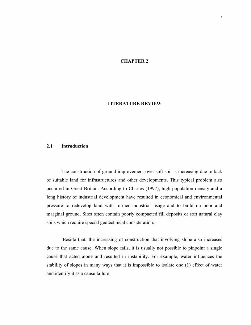
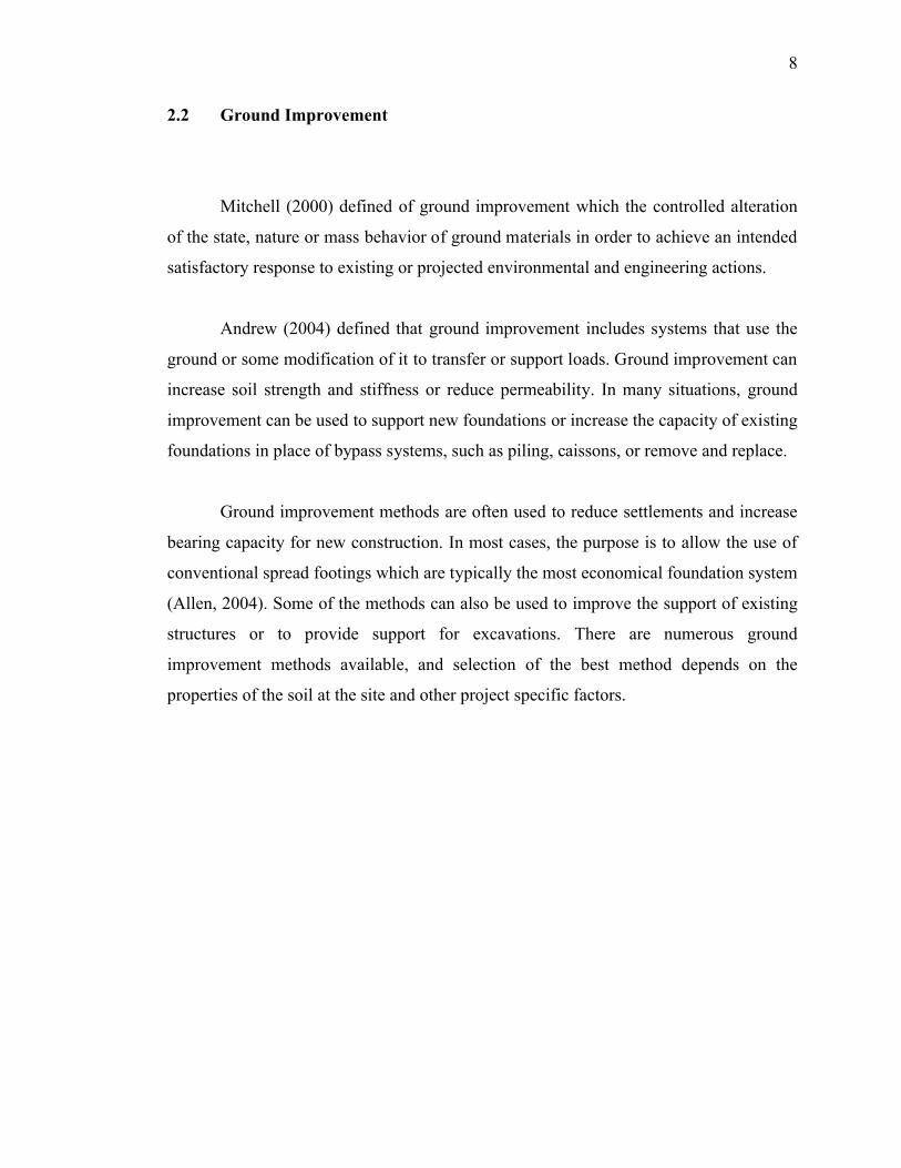
One (1) of the major functions of geotextile is filtration. For this purpose, water
must be able to flow freely through the fabric of the geotextile. Hence, the cross plane
hydraulic conductivity is an important parameter for design purpose (Das, 2002). It
should be realized that geotextile fabrics are compressible, however their thickness may
change depending on the effective normal stress to which they are being subjected.
Figure 2.1 shows in-plane flow in geotextile. The change in thickness under normal
stress also changes the cross-plane hydraulic conductivity of a geotextile, as shown in
Figure 2.2. Geotextile currently available commercially have thickness that varies from
about 0.25mm to 7.6mm. The mass per unit area of these geotextile ranges from about
150 to 700g/cm2.
11
Figure 2.1: In-plane flow in geotextile (Das, 2002)
Figure 2.2: Cross-plane flow through geotextile (Das, 2002)
12
2.3.2 Densification of Soil
The densification of granular soil by compaction has been extensively carried out
in earthwork construction and ground improvement (Saturo, 1997). Then the
engineering properties of compacted granular soils that are most relevant to geotechnical
engineers are shear strength, compressibility and permeability (Nobucha, 1997).
According to Charles (2004), the utility of densification as a means of ground
improvement method rests primarily on three (3) factors. There are;
1) An increase in the density of a soil generally results in improved ground
behavior, such as increased stiffness and strength.
2) Many of hazards for buildings on untreated ground are associated with
volumetric compression of the ground. Therefore appropriate ground
treatment by densification can act as a type of inoculation by subjecting the
ground to a form of the hazard before construction on the ground take places.
3) Soils are generally inelastic and strains are non-recoverable. Therefore once
the ground has been densified by ground treatment it will remain densified,
and subsequently vulnerability to volume compression will be greatly
reduced.
According to Charles (2004), there are two (2) principle form if densification
which is compaction and consolidation. Compaction may be more effective in reducing
vulnerability to liquefaction, whereas consolidation may be more effective in reducing
compressibility, because in both these cases the remedy closely resembles the problem.
Thus, treatment by compaction is particularly effective in reducing subsequent
susceptibility to self compaction due to vibration, and treatment by consolidation in
reducing settlement due to subsequent loading.

13
2.3.3 Preloading
Preloading generally refers to the process of compressing the soil under applied
vertical stress prior to construction and placement of the final construction load
(Stapelfeldt, 1999). The two (2) common preloading techniques are conventional
preloading, as shown in Figure 2.3. For example an embankment and vacuum induced
preloading. Preloading reduces total settlement and may allow for economical selection
of foundation system. Vertical drains speed up the process while preloading reduces the
amount of post consolidation settlement (Hausmann, 1990).
Figure 2.3: Conventional preloading schematic diagrams (Stapelfeldt, 1999)